mercury switch-to-microswitch retrofit kit ka349we ... · ii mercury switch to microswitch retrofit...
TRANSCRIPT

Mercury switch to microswitch retrofit kit KA349WE installation instructions
COOPER POWERSERIES
Reclosers MN280022EN
Effective October 2015Supersedes S280-40-10 April 2014

ii MERCURY SWITCH TO MICROSWITCH RETROFIT KIT KA349WE INSTALLATION INSTRUCTIONS MN280022EN October 2015
DISCLAIMER OF WARRANTIES AND LIMITATION OF LIABILITY
The information, recommendations, descriptions and safety notations in this document are based on Eaton Corporation’s (“Eaton”) experience and judgment and may not cover all contingencies. If further information is required, an Eaton sales office should be consulted. Sale of the product shown in this literature is subject to the terms and conditions outlined in appropriate Eaton selling policies or other contractual agreement between Eaton and the purchaser.
THERE ARE NO UNDERSTANDINGS, AGREEMENTS, WARRANTIES, EXPRESSED OR IMPLIED, INCLUDING WARRANTIES OF FITNESS FOR A PARTICULAR PURPOSE OR MERCHANTABILITY, OTHER THAN THOSE SPECIFICALLY SET OUT IN ANY EXISTING CONTRACT BETWEEN THE PARTIES. ANY SUCH CONTRACT STATES THE ENTIRE OBLIGATION OF EATON. THE CONTENTS OF THIS DOCUMENT SHALL NOT BECOME PART OF OR MODIFY ANY CONTRACT BETWEEN THE PARTIES.
In no event will Eaton be responsible to the purchaser or user in contract, in tort (including negligence), strict liability or other-wise for any special, indirect, incidental or consequential damage or loss whatsoever, including but not limited to damage or loss of use of equipment, plant or power system, cost of capital, loss of power, additional expenses in the use of existing power facilities, or claims against the purchaser or user by its customers resulting from the use of the information, recommendations and descriptions contained herein. The information contained in this manual is subject to change without notice.

iiiMercury switch to Microswitch retrofit kit kA349we instAllAtion instructions S280-40-10 Month 2015
Contents
SAFETY INFORMATIONSafety instructions . . . . . . . . . . . . . . . . . . . . . . . . . . . . . . . . . . . . . . . . . . . . . . . . . . . . . . . . . . . . . . . . . . . . . . . . . . . . . . iv
PRODUCT INFORMATIONIntroduction . . . . . . . . . . . . . . . . . . . . . . . . . . . . . . . . . . . . . . . . . . . . . . . . . . . . . . . . . . . . . . . . . . . . . . . . . . . . . . . . . . . .1
Handling and storage . . . . . . . . . . . . . . . . . . . . . . . . . . . . . . . . . . . . . . . . . . . . . . . . . . . . . . . . . . . . . . . . . . . . . . . . . . . . .1
Quality standards. . . . . . . . . . . . . . . . . . . . . . . . . . . . . . . . . . . . . . . . . . . . . . . . . . . . . . . . . . . . . . . . . . . . . . . . . . . . . . . .1
Additional information . . . . . . . . . . . . . . . . . . . . . . . . . . . . . . . . . . . . . . . . . . . . . . . . . . . . . . . . . . . . . . . . . . . . . . . . . . . .1
INSTALLATIONReposition contact bar . . . . . . . . . . . . . . . . . . . . . . . . . . . . . . . . . . . . . . . . . . . . . . . . . . . . . . . . . . . . . . . . . . . . . . . . . . . .3
Disconnect terminal wires . . . . . . . . . . . . . . . . . . . . . . . . . . . . . . . . . . . . . . . . . . . . . . . . . . . . . . . . . . . . . . . . . . . . . . . . .3
Remove microswitch switch SW1 . . . . . . . . . . . . . . . . . . . . . . . . . . . . . . . . . . . . . . . . . . . . . . . . . . . . . . . . . . . . . . . . . .4
Remove mercury switch SW3. . . . . . . . . . . . . . . . . . . . . . . . . . . . . . . . . . . . . . . . . . . . . . . . . . . . . . . . . . . . . . . . . . . . . .4
Remove mercury switch SW2. . . . . . . . . . . . . . . . . . . . . . . . . . . . . . . . . . . . . . . . . . . . . . . . . . . . . . . . . . . . . . . . . . . . . .4
Install microswitch SW2 . . . . . . . . . . . . . . . . . . . . . . . . . . . . . . . . . . . . . . . . . . . . . . . . . . . . . . . . . . . . . . . . . . . . . . . . . .6
Install microswitches SW1 and SW 3 and new switch cam . . . . . . . . . . . . . . . . . . . . . . . . . . . . . . . . . . . . . . . . . . . . . . .8
KIT KA349WE PARTS LISTPart identification . . . . . . . . . . . . . . . . . . . . . . . . . . . . . . . . . . . . . . . . . . . . . . . . . . . . . . . . . . . . . . . . . . . . . . . . . . . . . . .10
TESTINGTesting . . . . . . . . . . . . . . . . . . . . . . . . . . . . . . . . . . . . . . . . . . . . . . . . . . . . . . . . . . . . . . . . . . . . . . . . . . . . . . . . . . . . . . .11

iv MERCURY SWITCH TO MICROSWITCH RETROFIT KIT KA349WE INSTALLATION INSTRUCTIONS MN280022EN October 2015
The instructions in this manual are not intended as a substitute for proper training or adequate experience in the safe operation of the equipment described. Only competent technicians who are familiar with this equipment should install, operate, and service it.
A competent technician has these qualifications:
• Is thoroughly familiar with these instructions.
• Is trained in industry-accepted high and low-voltage safe operating practices and procedures.
• Is trained and authorized to energize, de-energize, clear, and ground power distribution equipment.
• Is trained in the care and use of protective equipment such as arc flash clothing, safety glasses, face shield, hard hat, rubber gloves, clampstick, hotstick, etc.
Following is important safety information. For safe installation and operation of this equipment, be sure to read and understand all cautions and warnings.
Safety instructionsFollowing are general caution and warning statements that apply to this equipment. Additional statements, related to specific tasks and procedures, are located throughout the manual.
Safety for life!
SAFETYFOR LIFE
!SAFETYFOR LIFE
Eaton meets or exceeds all applicable industry standards relating to product safety in its Cooper Power™ series products. We actively promote safe practices in the use and maintenance of our products through our service literature, instructional training programs, and the continuous efforts of all Eaton employees involved in product design, manufacture, marketing, and service.
We strongly urge that you always follow all locally approved safety procedures and safety instructions when working around high voltage lines and equipment, and support our “Safety For Life” mission.
Safety information
DANGERHazardous voltage. Contact with hazardous voltage will cause death or severe personal injury. Follow all locally approved safety procedures when working around high- and low-voltage lines and equipment. G103.3
WARNING Before installing, operating, maintaining, or testing this equipment, carefully read and understand the contents of this manual. Improper operation, handling or maintenance can result in death, severe personal injury, and equipment damage. G101.0
WARNING This equipment is not intended to protect human life. Follow all locally approved procedures and safety practices when installing or operating this equipment. Failure to comply can result in death, severe personal injury and equipment damage. G102.1
WARNING Power distribution and transmission equipment must be properly selected for the intended application. It must be installed and serviced by competent personnel who have been trained and understand proper safety procedures. These instructions are written for such personnel and are not a substitute for adequate training and experience in safety procedures. Failure to properly select, install or maintain power distribution and transmission equipment can result in death, severe personal injury, and equipment damage. G122.2
This manual may contain four types of hazard statements:
DANGER Indicates an imminently hazardous situation which, if not avoided, will result in death or serious injury.
WARNING Indicates a potentially hazardous situation which, if not avoided, could result in death or serious injury.
CAUTION Indicates a potentially hazardous situation which, if not avoided, may result in minor or moderate injury.
CAUTIONIndicates a potentially hazardous situation which, if not avoided, may result in equipment damage only.
Hazard Statement Definitions

1MERCURY SWITCH TO MICROSWITCH RETROFIT KIT KA349WE INSTALLATION INSTRUCTIONS MN280022EN October 2015
Product information
IntroductionThis manual explains how to replace mercury switches with microswitches on Eaton’s Cooper Power™ series electronically operated reclosers. It contains instructions for:
1. Removing mercury switches from switch SW2 and SW3 positions.
2. Removing existing microswitch from the switch SW1 position and installing it in the switch SW2 position.
3. Installing new microswitches in the switch SW1 and SW3 positions.
Read this manual firstRead and understand the contents of this manual and follow all locally approved procedures and safety practices before installing or operating this equipment.
These instructions cannot cover all details or variations in the equipment, procedures, or process described nor to provide directions for meeting every possible contingency during installation, operation, or maintenance. For additional information, please contact your Eaton representative.
Acceptance and initial inspectionThis product is completely assembled, tested, and inspected at the factory. It is carefully calibrated, adjusted, and in good condition when accepted by the carrier for shipment.
Upon receipt, inspect the carton for signs of damage. Unpack the kit and inspect it thoroughly for damage incurred during shipment. If damage is discovered, file a claim with the carrier immediately.
Handling and storageBe careful during handling and storage of equipment to minimize the possibility of damage.
Quality standardsISO 9001 Certified Quality Management System
Additional informationIn addition to this manual, also refer to the appropriate maintenance manual for the model of recloser being equipped with microswitches.
• S280-40-3, Type RE, Three-Phase Maintenance Instructions
• S280-40-4, Type WE, Three-Phase Maintenance instructions
• S280-40-5, Types RVE and WVE, Three-Phase Maintenance Instructions.
• S280-40-6, Types VWE and VWVE Maintenance Instructions
• S280-40-7 Types RXE and WE Maintenance Instructions
• S280-40-8, Types RVE and WVE Maintenance Instructions
IMPORTANTThis is a generic procedure for replacing existing mercury switches with microswitches. It pertains to all electronically operated reclosers from Eaton equipped with such switches. However, some models of reclosers may have small parts used only on that particular design. Also, some reclosers may employ various shim washers to compensate for tolerance variation. If such parts are present, make note of them and be sure to reinstall them before returning the recloser to service.
Table 1. Ordering Information
Description Catalog Number
Mercury Switch to Microswitch Retrofit Kit KA349WE

2 MERCURY SWITCH TO MICROSWITCH RETROFIT KIT KA349WE INSTALLATION INSTRUCTIONS MN280022EN October 2015
Trip Solenoid
Switch SW3
Switch SW1
Main Shaft
Grommeted Cable Exit Hole and Terminal Block
Rotary Solenoid
Plastic Cable Retainer
Switch SW2
Handle Shaft (Yellow handle, manual trip shaft)
Contact Position Indicator Shaft
H Bracket
Shaft Spacer Spring
Two Large Trip Springs
Contact Bar
Figure 1. A Type WE recloser operating mechanism with new microswitches in place.

3MERCURY SWITCH TO MICROSWITCH RETROFIT KIT KA349WE INSTALLATION INSTRUCTIONS MN280022EN October 2015
Installation
Follow the appropriate recloser maintenance manual to remove the recloser from service. Transport it to a location suitable for performing the work required.
IMPORTANTBefore beginning the disassembly process, ensure the recloser is in the open position.
Refer to the recloser maintenance manual and untank the recloser. Remove operating mechanism from head and disconnect any auxiliary devices.
Place the recloser operating mechanism in a stable position permitting easy access to all sides of the unit.
Reposition contact barRepositioning the contact bar permits greater access to the mechanism’s switch areas. Reposition the contact bar by removing retaining pins at points indicated in Figure 2.
1. Remove C rings from contact bar retainer pin at trip solenoid end of mechanism and discard.
2. Note position of any washers, then remove and save them.
3. Slide pin aside until free of contact bar and springs.
4. Repeat Steps 1-3 on the middle retaining pin.
Figure 2. Contact bar retaining rods to be removed.
After the contact arm is free of the end- and mid- retainers, raise and secure it, so it remains out of the way for the switch replacement process (Figure 3).
Figure 3. Repositioning contact bar.
Disconnect terminal wiresDisconnect wires at the terminal block under the rotary solenoid.
1. Disconnect wires at terminals A, C, D, F, and N on the lower row of terminals (Figure 4).
2. Disconnect plastic cable retainer and discard (Figure 4). Save hardware.
Figure 4. Terminal block and lower terminal identification.
Solenoid end of mechanism
Contact barMiddle retaining pin
Retaining pins
N F E D C B A
Cable exit hole with grommet
Plastic cable retainer placement

4 MERCURY SWITCH TO MICROSWITCH RETROFIT KIT KA349WE INSTALLATION INSTRUCTIONS MN280022EN October 2015
Remove microswitch switch SW1otee:N SW1 refers to the switch position. The existing
microswitch is removed from the switch SW1 position and reinstalled in the switch SW2 position.
1. Loosen switch SW1 terminal screws and detach cable wire (Figure 5).
Figure 5. Terminal and mounting screws on switch SW1.
2. Remove hardware holding SW1 mounting plate to frame. Lift plate from frame. Save nut and lockwasher.
3. Remove hardware holding switch to mounting plate. Save hardware and switch for later use. Discard mounting plate.
4. Remove and retain cable from switch.
Remove mercury switch SW3
WARNINGHazardous material. Do not open mercury switches or come in direct contact with switches exhibiting any sign of mercury leakage. Exposure to mercury can cause serious health problems. T281.0
1. Use a punch to drive out the roll pin that is holding switch SW3 and mounting block to main shaft (Figure 6). Discard roll pin.
2. Remove mounting block and attached switch assembly. Remove and discard mounting block. Dispose of mercury switch following local hazardous waste procedures.
IMPORTANTSW2 and SW3 switches contain mercury. Dispose of these switches in accordance with all federal, state, and locally approved mercury disposal guidelines and regulations.
Figure 6. Removing switch SW3 from main shaft.
Figure 7. Springs and retaining pins.
Remove mercury switch SW2
WARNINGHazardous material. Do not open mercury switches or come in direct contact with switches exhibiting any sign of mercury leakage. Exposure to mercury can cause serious health problems. T281.0
Remove springsotee:N Position of existing spacers and washers.
1. Detach and discard two C rings from spring retaining pin at outer frame (Figure 7). (Oil-interrupting unit with two spacers shown. Vacuum units have no spacers here.)
2. Slide spring retaining pin aside until able to detach the two large springs from the spring retaining pin.
3. Detach the upper small spring from the retaining pin in the handle shaft assembly as shown in Figure 7.
4. Remove and discard two C rings from the retaining pin.
5. Remove and save retaining pin.
6. Detach the two, small lower springs from retaining pin marked ‘pin’ in Figure 7.
7. Remove and retain the two spacers and pin.
!
!
Screws holding mounting plate to frame
Mounting plate
Switch SW1 Cam
Screws holding microswitch to mounting plate
Mercury SwitchCable
Terminal screws
Lower two small springs, detach here
Upper small spring, detach here
Handle Shaft
Mercury Switch
Spring retaining pin, stip 1
Two large springs, attached to spring retaining pin
Spacers
C Ring
Pin
Spacers
Switch SW3
Roll pin
Mounting block

5MERCURY SWITCH TO MICROSWITCH RETROFIT KIT KA349WE INSTALLATION INSTRUCTIONS MN280022EN October 2015
Replace handle shaft assemblyotee:N Orientation and assembly of handle shaft (yellow
handle, manual trip shaft) before proceeding.
1. Remove and discard cotter pin from roll pin on end of handle shaft (Figures 8 and 11).
Figure 8. Ends of handle shaft.
2. Use a punch to drive roll pin from shaft. Discard roll pin.
3. Remove and save end washer and spring.
4. Drive roll pins from handle reset cam and handle reset lever attached to handle shaft and discard (Figure 9).
Figure 9. Handle shaft assembly.
5. Remove C ring from handle shaft, at end where cotter pin was removed, and discard (Figure 8).
6. Remove and save spacer washer(s).
7. Remove and discard two remaining C rings from handle shaft, beginning with outermost C ring.
8. Slide existing handle shaft from frame, noting position of shaft spacer (Figure 11). Discard shaft, cam, and lever; retain spacer.
9. Switch SW2 cable runs along the side of frame and is held in place by plastic retainers (Figure 10). Remove and save the retainers and hardware. Discard cable. Dispose of mercury switch following local hazardous waste procedures.
IMPORTANTSW2 and SW3 switches contain mercury. Dispose of these switches in accordance with all federal, state, and locally approved mercury disposal guidelines and regulations.
10. Scribe new handle shaft assembly (Item 3) to mark orientation of cam and lever to shaft and shaft to frame.
Carefully remove roll pins, cam, and lever from new shaft (Figure 9).
Figure 10. Switch SW2 cable routing.
11. Slide new shaft into frame keeping orientation the same as found when removing the old one. Slide shaft through frame, new cam, new lever, old spacer, remaining old lever, new C ring (Item 19), and frame (Figure 11).
Figure 11. Handle shaft assembly.
12. Match scribe marks between shaft and new handle reset level. Hold new lever in alignment with shaft with a punch inserted via the notched side of lever. Gently drive roll pin into lever via the rounded side of the lever.
13. Match scribe marks between new handle reset cam and shaft. Hold cam in alignment with shaft with a punch inserted via the notched side of cam. Gently drive roll pin into cam via the rounded side of the cam.
14. Turn shaft so the rounded sides of lever and cam are away from the mechanism to match orientation before replacement.
15. Tighten new C ring (Item 19) on shaft on inner edge of frame.
16. Install new C ring (Item 19) on shaft, outside of frame, and tighten.
17. Reinstall spacers, new C ring (Item 19), spring, end washer, new roll pin (Item 20), and new cotter pin (Item 18) on end of handle shaft.
Handle reset camHandle reset lever
C ringsRoll pins
C ring
Roll pin
Cotter pin
Spacer washers(number may vary)
C ring
Spring
C rings
Endwasher
Shaft
Spacer
Switch SW2 cable and a cable retainer.
Existing lever, not replaced
LeverHandle Shaft
Cam
C Ring
Spacer
6 MERCURY SWITCH TO MICROSWITCH RETROFIT KIT KA349WE INSTALLATION INSTRUCTIONS MN280022EN October 2015
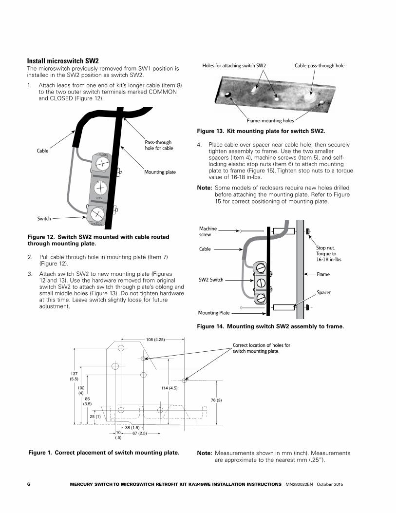
Install microswitch SW2The microswitch previously removed from SW1 position is installed in the SW2 position as switch SW2.
1. Attach leads from one end of kit’s longer cable (Item 8) to the two outer switch terminals marked COMMON and CLOSED (Figure 12).
Figure 12. Switch SW2 mounted with cable routed through mounting plate.
2. Pull cable through hole in mounting plate (Item 7) (Figure 12).
3. Attach switch SW2 to new mounting plate (Figures 12 and 13). Use the hardware removed from original switch SW2 to attach switch through plate’s oblong and small middle holes (Figure 13). Do not tighten hardware at this time. Leave switch slightly loose for future adjustment.
Figure 13. Kit mounting plate for switch SW2.
4. Place cable over spacer near cable hole, then securely tighten assembly to frame. Use the two smaller spacers (Item 4), machine screws (Item 5), and self-locking elastic stop nuts (Item 6) to attach mounting plate to frame (Figure 15). Tighten stop nuts to a torque value of 16-18 in-lbs.
otee:N Some models of reclosers require new holes drilled before attaching the mounting plate. Refer to Figure 15 for correct positioning of mounting plate.
Figure 14. Mounting switch SW2 assembly to frame.
Figure 1. Correct placement of switch mounting plate. otee:N Measurements shown in mm (inch). Measurements are approximate to the nearest mm (.25”).
COMMON
CLOSED
OPEN
Pass-through hole for cable
Mounting plate
Cable
Switch
Holes for attaching switch SW2 Cable pass-through hole
Frame-mounting holes
Machine screw
Cable
SW2 Switch
Mounting Plate
Spacer
Frame
Stop nut. Torque to 16-18 in-lbs
108 (4.25)
86(3.5)
102(4)
137(5.5)
10(.5)
38 (1.5)67 (2.5)
114 (4.5)
25 (1)
76 (3)
Correct location of holes forswitch mounting plate.

7MERCURY SWITCH TO MICROSWITCH RETROFIT KIT KA349WE INSTALLATION INSTRUCTIONS MN280022EN October 2015
5. Route switch SW2 cable along frame wall and pull it through the cable exit hole to terminal block (Figures 4 and 10). Do not attach cable leads to terminal block at this time.
6. Use the previously removed hardware and plastic cable retainers to secure cable to frame (Figures 10 and 16).
Figure 15. Plastic cable retainer assembly.
Completing switch SW2 assemblyMatching original orientation, reinstall parts removed.
1. Reinstall pin, spacers, and two, small lower springs (Figure 17). (Vacuum unit without spacers shown. Oilinterrupting units have two spacers. )
otee:N If no tool is available to grab springs, place a piece of strong string through spring’s connecting loop and pull spring into place. Once spring is connected, pull string clear.
Figure 16. Reinstall springs and retaining pins.
2. Reinstall retaining pin, new C rings (Item 22), and small upper spring.
3. Slide spring retaining pin through the two large springs, spacers, and new C rings (Item 21). Tighten C rings.
4. With H bracket disengaged, gently push down on switch SW2 until hearing a click as switch contact encounters cam and closes (Figure 18).
Figure 17. Side view, switch SW2 assembled to mounting plate.
5. Hold switch in place where click is heard and tighten retaining hardware. Take care not to over tighten and damage switch.
6. Recheck all work. Engage and disengage the H bracket using the following directions:
A. Turn the handle shaft clockwise with a pair of pliers to engage and latch the H bracket.
B. Turn the handle shaft counterclockwise with a pair of pliers to disengage the H bracket.
Make sure mechanism does not encounter interference during movement. Adjust spacers as needed to eliminate any interference.
Gently push down for final switch adjustment
Approximate placement of microswitch Stop Nuts: Torque to 13-15 in-lbs after adjustment
Cable Pass Through
Mounting holes, plate to frame
Two large springs attached to spring retaining pin
Spring retaining pinUpper small spring, attach here
Spacers
Pin
Handle shaft
H bracket
Lower two small springs, attach here

8 MERCURY SWITCH TO MICROSWITCH RETROFIT KIT KA349WE INSTALLATION INSTRUCTIONS MN280022EN October 2015
Install microswitches SW1 and SW 3 and new switch cam
Preparing main shaft1. Block mechanism with a screwdriver or other device to
prevent plungers from descending into main contacts when tension is relieved (Figure 19).
Figure 18. Mechanism blocked with screwdriver.
2. Detach large lower spring (Figure 20) to relieve tension on operating mechanism.
Figure 19. Spring attachment in lower part of mechanism.
3. Remove and discard two large retaining E rings from main shaft (Figure 21).
4. Remove the machine screw, spacer, and nut that connect the main shaft to closing contactor toggle.
Figure 20. Items to remove on main shaft.
5. Use punch to remove roll pin holding old SW1 cam. Discard roll pin. (Figure 21).
6. Remove large roll pin to free shaft. Save roll pin.
7. Slide main shaft aside to gain clearance for removing old microswitch cam. Note orientation of cam on shaft. Remove and discard cam.
Install new cam for SW11. Slide new switch cam (Item 15) onto main shaft. Orient
cam as shown in Figures 22 and 23.
Figure 21. Orientating cam for switches SW1 and SW3.
Figure 22. Cam installed. Note position of spring and roll pins.
2. Reinsert main shaft into frame.
3. Use new spring pin (Item 17) from kit to secure cam on main shaft.
4. Reinsert the saved, large roll pin.
5. Attach two new E rings (Item 16) to main shaft.
6. Reinstall machine screw, spacer, and nut connecting main shaft to closing contactor toggle.
Large roll pin Main shaft Spring pin Cam
Push down to position switchbefore tightening
Spring PinCavity
Attach cable leads toCommon and Open terminals
(both switches)
Switch SW1
Mounting bracket
RotarySolenoid
Frame
Slotted Hole
Cam flat nearest frame faces up toward switch
Switch SW3 on far side of bracket
Old switch SW1 cam Closing contactor toggle
E ring
Main shaft Large roll pin

9MERCURY SWITCH TO MICROSWITCH RETROFIT KIT KA349WE INSTALLATION INSTRUCTIONS MN280022EN October 2015
Install microswitches SW1, SW31. Attach the new SW1 and SW3 microswitch assembly
(Item 2) to frame using screws (Item 11), larger, round spacers (Item 10), external tooth lockwashers (Item 13), and stop nuts (Item 12), (Figure 24). Do not tighten at this time.
Figure 23. Attach SW1/SW3 microswitches to frame.
2. Gently push switch assembly down until hearing a click as switch SW3 contact meets cam and closes. Secure switch in position at which click is heard (Figure 22).
Attach cable leadsAttach leads from cables switch SW1 and SW3 as described in the steps outlined below. On both switches, connect one lead to the end terminal marked common and one lead to the middle terminal marked open (Figure 24).
1. Attach leads of the short microswitch cable originally removed from old switch SW1 to new switch SW3.
2. Attach leads of shorter cable in kit (Item 9) to new switch SW1.
3. Route SW1 and SW3 cables to terminal block (Figure 25).
4. Secure cables with plastic cable tie (not supplied) and plastic cable retainer (Item 1) from kit. Use existing hardware to attach new cable retainer in the same position used by the old one.
5. At the terminal block, make the following connections (refer to Figures 5 and 27 for terminal identification):
A. Switch SW1, connect leads to terminals C and D.
B. Switch SW2, connect leads to terminals F and N.
C. Switch SW3, connect leads to terminals A and N.
Figure 25. Terminal block connections.
6. Verify the following connections to terminal block are in place:
A. Rotary solenoid leads connected to terminals E and F.
B. Trip solenoid leads connected to terminals A and B.
Complete installation1. Reconnect the large spring in lower portion of
mechanism (Figure 20).
2. Remove blocking mechanism (Figure 19).
3. Reconnect contact bar. Make sure to reinstall all washers or spacers that may have been removed when disconnecting it (Figure 23).
4. Check work and ensure all fasteners are tight. Inspect mechanism for loose parts; if found, remove them.
5. Test switches as outlined in the Testing section.
6. Follow procedures in appropriate maintenance manual to tank recloser and return it to service.
COMMON
CLOSEDCLOSED
OPEN
COMMON
OPEN
Slotted hole ofbracket
Switch SW3
Machine screw
SpacerFrame
External tooth lockwasher
Switch SW1
Stop Nut Torque to 18-20 in-lbs
Cable
Switch SW2 Switch SW1
Switch SW3
Rotary Solenoid
TripSolenoid
ABCDEFN
Figure 24. Microswitches SW1 and SW3 in place.

10 MERCURY SWITCH TO MICROSWITCH RETROFIT KIT KA349WE INSTALLATION INSTRUCTIONS MN280022EN October 2015
1
3
2
8
15
719
10
11
16
20
522
2118
17
9
4
613
12
Table 2. Kit KA349WE Part Identification
Item Part Number Description Kit Qauntity
1 KA20060001 CABLE CLIP 1
2 6A00349701 MICROSWITCH ASSEMBLY (SW1 and SW3) 1
3 WEA0088001 HANDLE SHAFT ASSEMBLY 1
4 KA30070187 STAINLESS STEEL SPACER 2
5 7215-15-108137A 1.37” LG RD HD MACH.SCR.;#8-32 UNC-2A 2
6 KA20200005 ELASTIC STOP NUT; #8-32 NC3 2
7 WE00160 HANDLE SWITCH MOUNTING PLATE 1
8 WEA0089001 LEAD WIRE ASSEMBLY 1
9 WEA0087001 LEAD WIRE ASSEMBLY 2
10 KA30090019 ALUMINUM SPACER 2
11 7215-15-110137A SLOTTED RD HD MACH.SCR.;#10-24 UNC-2A 2
12 KA20200013 ELASTIC STOP NUT, SS, #10-24 2
13 9011-32-010000A EXTERNAL TOOTH LOCKWASHER; #10 PL/F 2
14 KA20480506 Rev: 03 S280-40-10 MERCURY SWITCH TO MICROSWITCH KIT INSTALLATION INSTRUCTIONS 1
15 WE00161002 MAINSHAFT CAM 1
16 9710-01-625000A TYPE “E” RETAINING RING; 0625 NOM. SHAFT 2
17 9708-01-125100C SPRING PIN 1
18 9705-25-062100A 0.0625 X 1.00 COTTER PIN 1
19 9709-15-312000A STEEL TYPE “C” RETAINING RING; #WA-516 6
20 9708-01-125075C ROLL PIN 0.125 X 0.75 STEEL 1
21 9709-01-375000M STEEL TYPE “C” RETAINING RING; #WA-518 4
22 9709-01-250000M STEEL TYPE “C” RETAINING RING; #WA-514 4
Kit KA349WE parts list
Figure 27. KA349WE Mercury switch to microswitch kit parts. See Table 2 for individual part identification.

11MERCURY SWITCH TO MICROSWITCH RETROFIT KIT KA349WE INSTALLATION INSTRUCTIONS MN280022EN October 2015
Testing
Use an ohmmeter or multimeter to perform the following tests:
1. Testing one switch at a time, attach ohmmeter leads to switch terminal screws.
2. Check the switch for an open or closed condition as specified in Table 3.
3. If a switch fails test, review its positioning. If positioned correctly, review switch terminal and terminal block connections. If all connections are correct, check switch to make sure it actually opens and closes as its arm changes position. Review switch cam for correct position. Check cable wires to ensure continuity exists within each wire.
Table 3. Switch status for contact and lever positions
Recloser Contacts Manual Operating Lever SW1 (C & D Terminals) SW2 (F & N Terminals) SW3 (A & N Terminals)
Open Down Open Open Closed
Open Up Open Closed Closed
Closed Up Closed Closed Open

Eaton1000 Eaton BoulevardCleveland, OH 44122United StatesEaton.com
Eaton’s Cooper Power Systems Division2300 Badger DriveWaukesha, WI 53188United StatesEaton.com/cooperpowerseries
© 2015 EatonAll Rights ReservedPrinted in USAPublication No. MN280022ENKA2048-506 Rev 04
Eaton is a registered trademark.
All trademarks are property of their respective owners.
For Eaton's Cooper Power series product information call 1-877-277-4636 or visit: www.eaton.com/cooperpowerseries.
!SAFETYFOR LIFE