menasha lock and dam haer no. wi-90 u* p@ at the...
TRANSCRIPT

Menasha Lock and Dam HAER No. WI-90 u* p@ At the confluence of Lake Butte Des Morts UJIC and the Lower Fox River, in the City of Menasha ^'^ Menasha 1<>-M£NA,
Winnebago County ^ Wisconsin
PHOTOGRAPHS
WRITTEN HISTORICAL AND DESCRIPTIVE DATA
HISTORIC AMERICAN ENGINEERING RECORD Rocky Mountain System Support Office
National Park Service P.O. Box 25287
Denver, Colorado 80225-0287

HISTORIC AMERICAN ENGINEERING RECORD
MENASHA LOCK AND DAM
HAER NO. WI-90
K//S
3-
Location:
Date of Construction:
Engineer:
Architect:
Present Owner:
Present Use:
Significance:
Project Information:
The Menasha Lock and Dam Complex is situated within the City of Menasha. The lock and dam is located within Section 15, T20N, R17E and Sections 15 and 22, T20N, R17E, respectively, in the Civil Town of Menasha, Winnebago County, Wisconsin.
UTM: Lock 16/383320/4895200; Dam 167384460/4894860; USGS Quadrangle: Neenah, Wisconsin 7.5' Series
1848-1985
United States Army Corps of Engineers with Contractors
United States Army Corps of Engineers with Contractors
United States Army Corps of Engineers
The Menasha lock is used exclusively for recreational purposes.
The Menasha Lock and Dam Complex allows passage for water craft around the Winnebago Rapids present at the outlet of the Lower Fox River and Lake Winnebago.
This documentation was undertaken in 1995 in accordance with requirements detailed in a June 19,1994 letter from Gregory D. Kendrick, Chief, History Branch, NPS to Dale Monteith, Acting Chief, Planning Division, USACOE, Detroit District. The Lower Fox system remains basically operational but was placed in caretaker status by the USACOE in 1982. The USACOE plans to divest itself of the Lower Fox system as soon as is feasible; therefore, NPS requested this documentation. All documentation conforms to HAER standards.
Dr. John D. Richards, Principal Investigator; Georgia A. Lusk, Patricia B. Richards, and Robert J. Watson, Project Archivists with Great Lakes Archaeological Research Center, Inc.; Joseph Paskus, Project Photographer.
r

Menasha Lock and Dam HAER No. WI-90 (page 2)

.■''ssrsi ■:./- :>*:&?zWTWF-
Menasha Lock and Dam HAER No. WI-90 (page 3)
MENASHA LOCKS AND DAMS
During the late 1840s, the Fox and Wisconsin Improvement Project was proposed as a way to provide economical water transport of the mineral resources of western Wisconsin to the eastern seaboard commercial centers. The Menasha Lock and Dam facility was constructed as part of the Fox and Wisconsin Improvement Project to allow safe passage through the Winnebago Rapids located between Doty Island and the town of Menasha.
In 1848, the Board of Public Works was created to monitor and administer the construction of numerous public projects including the Fox and Wisconsin Rivers Improvement Project.1 In September of that same year, Condy R. Alton was chosen as the Fox and Wisconsin Improvement Project's chief engineer responsible for surveying and assessing the existing facilities located along the Fox River. In addition, Alton was directed to provide suggestions and cost estimates to the Board for making the Fox River navigable for shipping vessels.2
After surveying the facilities at Menasha, Alton reported to the Board that navigation through the Winnebago Rapids could be accomplished with the construction of a lock and canal facility.3 The contract for the construction of the lock and dam facilities at Menasha was awarded to Curtis Reed, who paid the state $5000. for the contract.4 In 1849, Alton reported that the facilities near Menasha at the Winnebago Rapids were under construction.5 By 1850, a crib dam had been constructed and two-thirds of the canal had been excavated.6
In 1853, the state legislature passed a bill that granted the Fox and Wisconsin Improvement Company all rights and responsibilities attendant to the construction of the Fox-Wisconsin Waterway.7 By 1856, the steamer Aquila had successfully completed a journey from the Mississippi River to Green Bay. However, much of the Fox-Wisconsin route needed to be dredged deeper to allow vessels with deeper drafts to safely pass though the system.8 The inability to allow passage of larger commercial vessels contributed to the demise of the Fox and Wisconsin Improvement Company. When the company was unable to acquire additional funding and declared bankruptcy, it was reorganized as the Green Bay and Mississippi Canal Company in 1866.9
Construction responsibilities were transferred to the new company and a survey was initiated by the federal government during the same year. Major Charles Sutter was assigned the task of surveying all of the proposed route from Green Bay to the Mississippi River.10 During his 1866 survey, Sutter found two sets of navigation facilities associated with the Winnebago Rapids, one on the north channel near Menasha, and one on the south channel near Neenah.11 The Menasha facility included a canal, a lock, and a dam which were all operational at the time of the survey. Conversely, the facility at Neenah was no longer operational. Sutter also reported that the Menasha dam was actively employed for commercial use and would require the least amount of effort to improve.12
In 1872, the federal government purchased the Fox and Wisconsin Improvement Company from the Mississippi and Green Bay Canal Company. The government appointed Major D.C. Houston to manage the lock and dam system in 1873.13 One of Houston's first duties was to conduct another survey along the Fox-Wisconsin Waterway. Following the survey, Houston noted that a number of repairs had been conducted on the Menasha lock since 1866. He also noted that the canal had been deepened and widened.14
Beginning in the 1870s and continuing through the mid 1900s, the Menasha Lock and Dam facilities have undergone a number of repairs and general maintenance. For example, in 1875 the

Menasha Lock and Dam HAER No. WI-90 (page 4)
lock chamber was entirely drained in order to repair a leak in the lock floor.15 Nine years later, the lock was again temporarily closed to conduct major repairs in several areas. At that time both mitre sills, the lock chamber walls, and the upper and lower gate walls were reinforced. Additional repairs included the stripping and replanking of portions of the floors and side walls, as well as the replacement of the gates, hollow quoins, and foundation material.16 In 1887 repairs were made to the lower wing walls, and in 1889 the lock chamber was replanked, and new gates and mitre sills were installed.17
In 1934 and 1935, the U.S. Army Corps of Engineers reported the old timber dam at Menasha to be in an advanced state of decay, and as having inadequate flood discharge capacity for the regulation of Lake Winnebago water levels.l 8 Consequently, the Corps of Engineers recommended that the dam be rebuilt as soon as the necessary funds were available.19 Funds for the reconstruction of the Menasha dam were allocated in 1936, and the new dam was in place by the end of the 1937 construction season.20
Repair work continued on the Menasha Lock and Dam facility throughout the 1940s and 1950s. Two new taintor gates were installed on the dam sluiceway in 1941, and repairs to the lock chamber walls and gates were carried out.21 With commercial traffic beginning to wane on the Fox River by the beginning of the 1950s, the pace of construction and major repairs slowed at the Menasha Lock and Dam facility. The major repair project during this period was the replacement of the masonry sluice piers of the dam with piers constructed of poured concrete.22 At the time that the sluiceway piers were replaced, the six Menasha dam taintor gates were also replaced.23
Other repairs during the 1950s included the lining of the lock floor with asphalt, and the installation of a safety rail around the lock chamber.24
The last commercial vessel locked through the Lower Fox River in 1959. Following the demise of commercial traffic on the Fox River, the locks of the Lower Fox River have been primarily used for recreational purposes.25
Because of its location between Little Lake Butte des Morts and Lake Winnebago, the Menasha Lock receives heavy traffic from recreational boats traveling between the two lakes. Partly due to the recreational importance of the Menasha lock, the Corps of Engineers recommended that the lock be rebuilt.26 Design work began on the proposed lock in 1978, with rehabilitation of the existing structure beginning that year as well.27 Final work was completed on the Menasha lock in 1979, at a reported cost of $1,225,038.28
On July 24,1984, design plans for the reconstruction of the Menasha dam spillway and repairs of two sluice piers were approved by the Army Corps of Engineers Office in Detroit.29 The submitted plans were slightly modified during construction. Reconstruction of the Menasha dam was completed in 1985. The "as built" design plans were submitted to the Fox River Project Office in Kaukauna on September 17,1985.30
The 1985 rebuilding of the spillway and associated repairs to the sluice piers were the last major construction project to take place at the Menasha Lock and Dam facilities. Today, the Menasha lock is one of the busier facilities on the Fox River due to its location between Lake Winnebago and Little Lake Buttes des Morts.31 It is estimated that on a summer weekend, the lock provides passage to 200 to 300 water craft.32

Menasha Lock and Dam HAER No. WI-90 (page 5)
MENASHA DAM
The Menasha dam consists of a concrete structure that was built in two phases to replace the 1937 masonry and concrete dam. The first building phase took place in 1956, when the original masonry sluiceway piers and the sluiceway were replaced.33 The second building phase occurred in 1985, when the spillway was resurfaced.34 Although the Menasha dam is the most modern of the Fox River complexes, its current configuration reflects elements of each design and construction phase of its history. Therefore, the various construction phases will be discussed where applicable.
The existing Menasha dam extends a total of 400.5 feet in a northwest/southeast orientation, and spans the Menasha Channel between the mainland and Doty Island. The dam consists of two major sections, a spillway and a sluiceway. The spillway extends 246.5 feet from the right (northwest) dam abutment in a southeasterly direction and is attached to the sluiceway which extends the remaining 154 feet southeast to the left (southeast) abutment.35 The Menasha dam is anchored to bedrock by interlocking steel sheet piles on both the upstream and downstream sides of the Fox River and maintains a standard low water datum of 746.73 feet above sea level.36
Menasha Spillway
The spillway section of the Menasha dam which was constructed in 1937 includes a wing wall, right dam abutment, cut-off wall and the spillway proper.
The wing wall of the Menasha dam is a concrete structure designed to bridge the span between the right dam abutment and the right shoreline abutment. The wing wall was constructed as part of the 1937 dam, and has been little altered since. The wing wall is 3 feet wide at its maximum height of 14 feet 6 inches above the river's bed. The wall slopes riverward at a 12V:5H pitch.37 A 12 inch wide keyway is recessed into the downstream face of the wing wall and extends the entire height of the structure. The keyway mates the wing wall to the shoreline abutment. A similarly sized concrete key protrudes from the wing wall's upstream end and serves to attach the structure to the dam abutment.38
The right dam abutment connects the wing wall to the right Mill Street Bridge abutment. The wall of the right dam abutment is beveled at a 12V:5H slope. The top of the abutment is 3 feet wide and expands to 10 feet 3 1/2 inches at a point 1 foot 3 inches above the base. The abutment is 32 feet 9 inches long.39 The upper portion of the abutment is comprised of a series of three 1 foot 4 inch risers.
A 12 inch wide, 14 foot 6 inch high keyway is recessed into the downstream end of the abutment, and is designed to anchor the abutment to the wing wall. Twenty one 1 inch by 6 foot 8 inch steel dowels provide additional support at the joint between the abutment and the wing wall. A second keyway connects the abutment to the spillway structure. This keyway is 1 foot 11 inches in width and 10 feet 2 inches high and is recessed 5 1/2 inches into the abutment.40
A cutoff wall is situated perpendicular to the right dam abutment. The cutoff wall is 20 feet long and connects the right dam abutment to the shore. The wall is 15 feet 3 inches in height, 2 feet wide at the top and 3 feet wide at the base. The abutment end of the cut off wall is tapered to fit into a corresponding slot in the right dam abutment. The cut off wall is anchored to the underlying bedrock by 14 steel sheet piles extending 1 foot 3 inches above the river's bed.41

Menasha Lock and Dam HAER No. WI-90 (page 6)
During the 1985 rebuilding of the spillway, an additional 12 inches of concrete was added to the upper surfaces of the wing wall and the right dam abutment.42 The additional concrete was poured over two layers of rebar welded into 6 inch wire fabric and placed over the upper surfaces of the wing wall and the right dam abutment. The welded wire fabric is anchored to these surfaces by 3/8 inch diameter anchors bolted into 3/4 inch threaded sleeves which are imbedded into the upper surfaces of the wing wall and the right dam abutment. At the same time that the wing wall and the right dam abutment were resurfaced, a pipe handrail was added to both structures. The upper rail of the handrail stands 3 feet above the surface of the abutment and wing wall and is attached to 4 foot uprights imbedded 12 inches into the surfaces of both walls.43
The spillway of the Menasha dam, which was built in 1937, consists of 14 poured concrete construction sections comprising a total length of 246 feet 6 inches. Sections 1 to 13 are 17 feet 7 1/4 inches wide and section 14 is 17 feet 7 3/4 inches wide. All sections are 24 feet long and extend approximately 11 feet 6 inches above the river's bed to reach a crest elevation of 746.73 feet above sea level.44
Viewed in cross section, the upstream face of each spillway section is perpendicular to the river bottom. The crest is gently rounded by an external radius of 2 feet. The downstream face of the spillway describes a gentle "S" curve as it slopes at a 12V:8H pitch to a 2 foot 6 inch thickness at the extreme downstream toe of each section.45
Spillway sections are anchored to each other by mating tapered concrete keyways extending the full height of each section and forming a mortise and tenon joint. In addition, expansion joints between adjoining sections are filled with 1/32 inch thick soft sheet copper the full height of each section.46
Each section is anchored to bedrock on the upstream side by 16 inch wide interlocking steel sheet piles. The piles extend up from bedrock and are anchored to a 2 foot deep concrete key that runs the entire length of the dam. Piles are anchored at the top by 1 1/4 inch by 6 foot long steel bars with hooks at each end.47
Spillway construction was designed to maintain a standard low water datum of 746.73 feet above sea level above the dam. Low water elevation in the lower pool is 740.23 feet above sea level. Maximum anticipated flood level is estimated at 750.5 feet above sea level while maximum anticipated tailwater elevation is estimated to be 748.23 above se,a level.48
A series of fifty 1 1/2 inch by 1 foot 3 inch long sections of open galvanized pipe were inserted 3 inches downstream of the crest line to receive flash board pins. Each section of the spillway has two slightly beveled keyways recessed 5 1/2 inches into each end of the fourteen sections beginning 6 inches downstream from the crest line. Concrete tenons form a tetrahedral with the widest section measuring 1 foot 11 inches at the seam between two construction sections, narrowing to 1 foot 9 inches with a 1/32 inch by 1 foot 3 inch soft copper sheet running the entire height of the concrete mortise and expansion joint, and 3/8 inch by 1 foot by 11 foot 6 inch forming the construction joint. The seams between each spillway section are filled by 1/8 inch thick construction joints, with 1/8 inch thick expansion joints at every third joint beginning at the northwest abutment.49
During the 1985 resurfacing of the spillway, an additional 12 inches of concrete was added to the upper surfaces of the spillway section.50 Prior to the addition of the new concrete, 12 inches of concrete was removed from each spillway section from the vertical upstream face to a point a 12 foot 6 inch horizontal distance from the upstream face. Concrete was removed on the vertical upstream face to a point 2 feet 6 inches below the crest line of each spillway section. Following

Menasha Lock and Dam HAER No. WI-90 (page 7)
the removal of the old surface of the spillway sections, new concrete was poured over two layers of rebar welded into 6 inch wire fabric and placed into the void created by the removal of the old spillway surfaces. The welded wire fabric is anchored to these surfaces by 3/8 inch diameter anchors bolted into 3/4 inch threaded sleeves which are imbedded into the upper surfaces of the spillway sections. A series of 1 1/2 inch by 1 foot 3 inch long sections of open galvanized pipes used to receive flash board pins are imbedded 1 foot 3 inches into the crest line of each spillway section.51
Sluiceway
In 1956, the masonry concrete sluiceway and its masonry sluice piers were replaced by the existing concrete structure.52 Located on the southwest side of the Fox River, the sluiceway consists of six sluiceway sections, six sluice piers and a concrete abutment.53 The sluiceway measures 154 feet from the end of the spillway to the river side surface of the left dam abutment.54
The left dam abutment, which was constructed as part of the 1937 dam replacement, is of poured concrete construction, and measures 37 feet long and 4 feet wide.55 The left abutment is attached to a concrete retaining wall anchored to the south bank of the Fox River.56 Located on both sides of each pier is a 13 inch wide "stop log" slot which runs the entire height of the sluice pier. The stop log slots are 6 inches deep and are located 3 feet 9 inches behind the upstream nose of the pier.57
The sluiceway piers are tied into the sluiceway construction sections by two rectangular concrete keys and sections of rebar. The first key, located 3 feet from the downstream end of the sluice pier measures 10 feet in length, 2 feet in width, and protrudes 6 inches into the base of the pier. The second key, measuring 6 feet in length and 2 feet in width, is located 5 feet 6 inches downstream from the upstream nose of the pier, and also protrudes 6 inches into the base of the pier. The concrete keys are tied into the piers and sluiceway construction sections by sections of rebar placed in two rows around the outside edges of the pier.58
The sluiceway construction sections are roughly ramp-shaped in profile, gradually sloping from a height of 5 feet above the river bottom at their upstream ends to a maximum height of 6 feet above the river bottom crest line. The sluiceway construction sections maintain this height for a horizontal distance of 11 feet 10 inches from the crest line.59 The sluiceway construction sections are reinforced with horizontal sections of rebar. The seams between the sluiceway construction sections are tilled by construction joints.
Six steel taintor gates are hung in the openings created by the sluice piers. Installed in 1956, the sluice gates are 10 feet 9 inches high, and are hung on cast steel gate hinges. Each gate is connected to the gate hinges by end girders and bracing composed of angle iron. The upper and lower arms of the end girders are sections of angle iron bolted to the gate hinges. The arms of the end girders are braced with three sections of triangulated angle iron. Two of these angle iron sections are also connected to a thick steel web plate which spans the space between the upper and lower arms directly behind the taintor gate face. The space between gate end girders is spanned by sections of channel iron running the width of the gate and connecting the upper and lower arms of opposite gate end girders. Additional bracing between end girders is located behind the gate face at the top and bottom of the gate. A thick steel web plate is located directly behind the gate face at the centerline of the gate. This web plate is tied to the horizontal gate bracing by two sections of angle iron. The fronts of the sluiceway gates are faced with thick steel plates secured to the gate bracing and web plates by horizontal I beams. Seams between the plates are secured by strips of steel plate which extend the entire height of the taintor gate.60

Menasha Lock and Dam HAER No. WI-90 (page 8)
The sluiceway gates of the Menasha dam are operated by a "crab", a gate hoist which contains a pair of electric winches and moves from gate to gate along a track on top of the sluiceway.61 The crab mechanism is constructed on two 18 foot long, parallel sections of channel iron connected to each other by four 2 foot 3 inch sections of I beam.62 The crab winches are powered by a five horsepower motor mounted between a motor controller and a cast iron hand wheel on the crab frame. The cast iron hand wheel is located near the middle of the crab frame.63 The crab rides on two parallel sets of four channel iron sections which vary in length from 23 feet 11 3/4 inches to 25 feet 11 1/2 inches.64 The channel sections are connected by 12 parallel pairs of 2 foot 9 inch long by 8 inch thick iron I beam sections. The crab mechanism rides along a 3 foot 4 inch track gauge mounted along the downstream length of the sluiceway.65
In order to raise or lower a gate, the crab is positioned over the gate, and the winch chains are connected to the hoist chain connectors on the gate.66 Once positioned, the crab is attached to a power source, and the winches are engaged until the gate has been raised to the desired height. Once this height is reached, the crab is disconnected from the power source and moved to the next gate to be opened.67 The electric winches are capable of lifting the gate at a rate of 2 feet per minute. Conversely, it requires 61.5 revolutions of the hand wheel to lift the gate 1 foot.68
When not in use, the crab mechanism is housed in a wooden gate hoist house built over the sluiceway between the two sluice piers closest to the spillway.69 The gate hoist house is a four sided structure constructed on top of two horizontal timbers. The downstream support is a 4 inch wide by 8 inch thick by 23 foot long horizontal timber mounted 1 foot 3 inches above the top of the sluiceway pier section by 3/4 inch by 1 foot 6 inch anchor bolts, while the upstream side of the gate hoist house is built on a 4 inch by 4 inch sill plate bolted directly to the top of the sluiceway walkway planking.70 At each end of the sill plates, 4 inch by 4 inch wall studs are fastened directly to the sill plate. Between these beams, 2 inch by 4 inch studs have been spaced 2 feet apart, center to center.71 On top of the 4 inch by 4 inch wall studs, two 2 inch by 4 inch beams have been strung to form the top plate.
Two doors are located on the sluiceway side of the gate hoist house. The downstream doorway allows the crab to be moved along its track and positioned above the sluiceway gates. The upstream door is a personnel entry door which accesses the walkway. The upstream and downstream sides of the gate hoist house each contain a single window located in the center of the wall. The gate hoist house is covered with a moderately pitched, front-gabled asphalt shingle roof.72
A steel walkway spans the entire length of the sluiceway. The walkway consists of a total of eight sections of channel iron bolted to the sluiceway pier sections with 3/4 inch by 1 foot 6 inch split anchor bolts grouted in place.73 Each side of the walkway is comprised of four channel beams bolted end to end, and spaced so that the channels of opposite beams face one another. The interior space between the channel beams is spanned by I beams which have been bolted to the channel iron with 1/2 inch by 1 1/2 inch machine bolts.74 The horizontal I beam sections serve as support ribs spaced 8 feet 4 inches apart along the entire length of the walkway.
On the exterior of the walkway, sections of angle iron have been secured and spaced to form the uprights for a handrail. The handrail uprights are constructed of 4 foot sections of 2 1/2 by 2 1/2 by 1/4 inch angle iron. On each side of the walkway, two 155 foot lengths of 1/2 inch galvanized 7 strand wire rope has been threaded through holes drilled in the walkway uprights. The ends of the wire rope have been secured on the landward side of the sluiceway with galvanized guy clamps, and connected to the gate hoist house with an eye bolt fastened to a turnbuckle.75

Menasha Lock and Dam HAER No. WI-90 (page 9)
The original decking of the sluiceway walkway was made up of sections of wooden planking nailed down to cover the span between the channel beams.76 In recent years, this planking has been replaced with steel grating.
MENASHA CANAL
The Menasha lock is located within an artificially created canal which bypasses the Menasha dam to the north. By 1851, approximately two-thirds of the Menasha lock canal had been excavated. Work continued on the canal for an additional five years until the entire canal was completed in 1856.77
The existing Menasha lock canal measures approximately 4,350 feet in length, including the lock structure, which is located in the northernmost portion of the canal.78, The canal varies in width, ranging from 75 feet to 150 feet in most places, and achieving a 450 foot width in the area immediate to the upper lock gates.79 The banks of the Menasha lock canal have been riprapped with stone.
MENASHA LOCK
The Menasha lock has changed little since it was reconstructed in 1979. The lock consists of a 131 foot 1 inch lock chamber, a 43 foot 6 inch lower gate monolith, and a 38 foot 6 inch upper gate monolith.80
The lock chamber of the Menasha lock extends 131 feet 1 inch from quoin to quoin. Additionally, there is a 28 foot 6 inch upper gate monolith and a 12 foot lower gate monolith which increase the overall length of the lock to 211 feet 6 inches.81 The upper gate monolith, located at the upstream end of the lock, is defined as that part of the lock structure which houses the upper gate and the valves used for filling the lock, while the lower gate monolith is that area which houses the lower gate.
The walls of the upper gate monolith are spaced 33 feet 9 inches apart and are 43 feet 6 inches long 82 The upper gate monolith consists of 16 foot 2 1/2 inch long wall sections built on top of a poured concrete base. The base is a 6 foot thick concrete slab, 25 feet in width, and 43 feet 6 inches in length. The vertical walls are tapered from a top width of 3 feet 2 inches to a 6 foot 3 inch base. Directly behind the lock gates, the interior faces of the upper gate monolith walls are recessed 3 feet 9 inches in order to allow the gates to recess flush when fully opened.83
The upper gates of the Menasha lock are constructed from high-strength, low alloy, horizontal girders supported by vertical sections of 1/2 inch web plate.84 Both gates measure 20 feet 6 inches in width, and are 13 feet 7/8 inches tall. Each gate is comprised of five horizontal girders, including the specialized girders which make up the walk plate at the top of the gate, and the mitre bumper at the bottom of the gate. The spacing between the horizontal supports varies according to where they are located on the gate. The first horizontal girder, identified on the engineering plan as Girder 1, is situated 2 feet 7/8 inches below the walk plate. The next girder, Girder 2, is spaced 4 feet below Girder 1. The remaining members, Girders 3-4, are spaced 3 feet 6 inches apart.85
Each horizontal girder is constructed from 20 foot 6 inch long sections of 1/2 inch steel web plate which is beveled on both the quoin and mitre ends of the girder. The quoin end of the girder is that end closest to the lock wall, while the mitre end is that end of the girder adjacent to the mitre joint.86 At the quoin and mitre ends of the horizontal girders, 1 inch thick end plates have been welded between the girders.87 Vertical support between the horizontal girders is provided by 1/2 inch thick sections of steel web plate spaced at varying intervals along the girders. Beginning 2

Menasha Lock and Dam HAEE No. WI-90 (page 10)
feet 6 inches from the quoin end, a vertical web plate support is fastened between each of the horizontal girders using 3/8 inch filet welds on both sides of the vertical upright.88 Four additional vertical web plate supports are spaced 3 feet 10 1/2 inches from one another and fastened between each horizontal girder in a like manner. At the center of the gate, 3 by 3 by 3/8 inch angle iron has been substituted for the web plate on the lock side of the girder. The vertical web plate supports closest to the mitre end of the gate are spaced 2 feet 6 inches from the end of the gate.89
The bottom of Girder 4, which is the horizontal girder located closest to the upper lock sill plate, has been specially altered in order to form a seal with the sill plate when the lock gate is closed.90
At the bottom of the gate, a 6 1/2 inch high piece of 1/2 inch thick web plate has been bolted to the bottom of the girder with 3/4 inch diameter hex bolts.91 A rubber "J" seal is bolted to the lockside of this web plate, forming a water tight seal with the upper lock sill when the gate is closed.92
The top girder of each gate has been altered so it can serve as a walkway over the top of the upper gates. Tlie walkway was created by welding a 3/8 inch raised pattern walk plate to the 1/2 inch vertical web plate supports between the walkway and Girder l.93 In addition to the raised pattern walk plate, all/2 inch diameter galvanized pipe hand railing has been welded to both sides of the top girder along the entire width of both gates. The walkway railings have been designed so that they sustain a minimum clear width of 3 feet at the top of the gate. The walkway uprights are constructed from uprights spaced 3 feet 10 1/2 inches apart on both sides of the gate. Two horizontal railings are welded to the walkway uprights. The uppermost railing is located at the top of the uprights, and the lower railing 1 foot 9 inches below the upper railing 94
Two 18 foot diagonal straps connected to opposite gate corners provide additional support to the upper gates.95 The diagonals are made up of two sections of 4 foot wide, 3/4 inch thick plate straps welded to the gate corners. One of the straps is 10 feet 10 1/2 inches in length, while the second strap is 6 feet 10 1/2 inches in length.96 The adjoining ends of the diagonal straps have 12 inch long opposite threaded bolts filet welded on center of the strap to a 6 inch depth. The opposing bolts are tied together with a 9 1/2 inch long 2 1/4 inch diameter sleeve nut which is tightened until the desired amount of tension has been placed on the diagonals.97
The lock side surfaces of the upper lock gates are covered by 7/16 inch thick steel plate welded to the horizontal girders and vertical uprights.98 The pool side of the upper gate is equipped with 11/16 inch thick flange plates providing support along the horizontal girders and vertical uprights. Uniroyal "D" fenders have been attached to the flange plates on the pool side of the upper gates.99
The water level of the Menasha lock is raised through the operation of six butterfly valves located in the floor of the upper gate monolith. When the lock is to be flooded, the lock gates are closed by horizontal spars connected to geared vertical shafts enclosed within cast iron tripods mounted on both sides of the lock wall. 10° A removable bar is inserted into a socketed hub attached to a vertical shaft and serves as a handle with which to turn the shaft. In order to open or close the gate, the locktender must use the handle to rotate the vertical shaft by walking around the tripod.
Once the gate is closed and sealed, the butterfly valves are opened and water is allowed to flow through a culvert below the mitre sill and into the lock.101 The valves are operated by geared mechanisms connected to three hand levers mounted on the side of the upper gate monolith on both sides of the lock.102 Each hand lever is attached to a 1 1/4 inch square push rod which is linked to the valve shaft by a connector plate. When a hand lever is pulled up, the push rod and connector plate are directed downward rotating the valve shaft, which in turn opens the valve.103

Menasha Lock and Dam HABR No. WI-90 (page 11)
The walls of the lower gate monolith are spaced 33 feet 9 inches apart and are 43 feet 6 inches long 104 The upper gate monolith consists of 16 foot 2 1/2 inch wall sections built on top of a poured concrete base. The base is a 6 foot thick concrete slab, 25 feet in width, and 43 feet 6 inches in length. The vertical walls are tapered from a top width of 3 feet 2 inches to 6 feet 3 inches at the base. Directly behind the lock gates, the interior faces of the upper walls are recessed 3 feet 9 inches in order to allow the gates to recess flush when fully opened.105
The lower gates are opened and closed by horizontal spars which connect the inside of the gates to geared vertical shafts mounted on steel tripods on both sides of the lock wall. A removable bar is inserted into a socketed hub attached to a vertical shaft and serves as a handle with which to turn the shaft. In order to open or close the gate, the locktender must use the handle to rotate the vertical shaft by walking around the tripod. If the gates are to be opened, the locktender walks in a counterclockwise direction, and if the gates are to be closed, the locktender walks in a clockwise direction.
The lower gates of the Menasha lock are constructed from high-strength, low alloy, horizontal girders supported by vertical sections of 1/2 inch web plate.106 Both gates measure 20 feet 6 inches in width, and are 20 feet 7 1/4 inches tall. Each gate is comprised of eight horizontal girders, including the specialized girders which make up the walk plate at the top of the gate, and the mitre bumper at the bottom of the gate. The spacing between the horizontal supports varies according to where they are located on the gate. The first horizontal girder, identified on the engineering plan as Girder 5, is situated 1 foot 5 3/4 inches below the walk plate. The next four horizontal members (Girders 6-9) are spaced 3 feet 6 inches apart.107 Between Girder 9 and Girder 10, and between Girder 10 and Girder 11, the horizontal spacing is 2 feet. The discharge valves used in draining the lock are located between Girder 10 and Girder 11.
Each horizontal girder is constructed from 20 foot 6 inch long sections of 1/2 inch steel web plate which is beveled on both the quoin and mitre ends of the girder. The quoin end of the girder is that end closest to the lock wall, while the mitre end is that end of the girder adjacent to the mitre joint.108 At the quoin and mitre ends of the horizontal girders, 1 inch thick end plates have been welded between the girders.109 Vertical support between the horizontal girders is provided by 1/2 inch thick sections of web plate spaced at varying intervals along the girders. Beginning 2 feet 6 inches from the quoin end, a vertical web plate support is fastened between each of the horizontal girders using 3/8 inch filet welds on both sides of the vertical upright. Four additional vertical web plate supports are spaced 3 feet 10 1/2 inches from one another and fastened between each horizontal girder in a like manner. At the center of the gate, 3 by 3 by 3/8 inch angle iron has been substituted for the web plate on the lock side of the girder. The vertical web plate supports closest to the mitre end of the gate are spaced 2 feet 6 inches from the end of the gate.110
Girder 11, which is the horizontal girder located closest to the lock's sill plate, has been specially altered in order to form a seal with the sill plate when the lock gate is closed.l! l As with the other horizontal girders, the top of Girder 11 is made up of a 1 foot 8 1/2 inch wide sheet of 1/2 inch thick web plate. On the lock side of the gate, a 1 foot 5 inch high 11/16 inch thick flange plate has been welded to the bottom of this horizontal girder. On the lake side of the gate, a 9 inch high 7/16 inch thick flange plate has been fastened to the horizontal web plate in a like manner. The bottom of Girder 11 is formed by a 1/2 inch thick, 4 inch wide web plate welded in place. This bottom plate and the lake side flange plate are connected by a 1/2 inch by 4 inch stiff plate which has been welded in place. A rubber" J" seal is located along the bottom of Girder 11, forming a water tight seal with the sill gate when the gate is closed.112
The top girder of each gate has been altered so it can serve as a walkway over the top of the lower gates. The walkway was created by welding a 3/8 inch raised pattern walk plate to the 1/2 inch
Menasha Lock and Dam HAER No. WI-90 (page 12)
vertical web plate supports between the walkway and Girder 5.113 In addition to the raised pattern walk plate, a 1 1/2 inch diameter galvanized pipe hand railing has been welded to both sides of the top girder along the entire width of both gates. The walkway railings have been designed so that they maintain a minimum clear width of 2 feet 2 5/8 inches at the top of the gate. The walkway uprights are constructed from uprights spaced 3 feet 10 1/2 inches apart on both sides of the gate. Two horizontal railings are welded to the walkway uprights. The uppermost railing is located at the top of the uprights, and the lower railing is located 1 foot 9 inches below the upper railing.114
Two 21 foot 1 1/2 inch diagonal straps connected to opposite gate corners provide additional support to the lower gates.115 The diagonals are made up of two sections of 4 foot wide, 3/4 inch thick plate straps welded to the gate corners. One of the straps is 13 feet in length, while the second strap is 7 feet 10 1/2 inches in length.116 The adjoining ends of the diagonal straps have 12 inch long opposite threaded bolts filet welded on center of the strap to a 6 inch depth. The opposing bolts are tied together with a 9 1/2 inch long 2 1/4 inch diameter sleeve nut which is tightened until the desired amount of tension has been placed on the diagonals.117
The lock side surfaces of the lower lock gates are covered by 7/16 inch thick steel plate welded to the horizontal girders and vertical uprights.118 The lake side of the lower gate is equipped with 11/16 inch thick flange plates providing support along the horizontal girders and vertical uprights. Uniroyal "D" fenders have been attached to the flange plates on the lake side of the lower gates.119
Six discharge valves are located in the bottom of the lower gate between the girders identified as Girder 10 and Girder 11. The valves are butterfly type valves measuring 3 feet 11 3/4 inches in length, and 2 feet in height.120 Each lower gate valve is constructed from two pieces of 1/2 inch thick steel valve plates bolted on their tops and bottoms with eight 5/8 inch diameter hex bolts. A 3 inch square shaft is located along the horizontal centerline of the valve. The shaft is turned to a 2 15/16 inch diameter on each of its ends so that it may couple with a bearing fitting on each end. The square shaft serves as an axis upon which the valve pivots to an open or closed position.121
The discharge valves are operated by geared mechanisms connected to three hand levers mounted on top of each of the lower gates.122 Each hand lever is linked to the particular valve it operates by a 1 1/4 inch square push rod linked to a connector plate attached to the top of the valve. When a hand lever is pulled up, the push rod and connector plate are directed downward, moving the valve to a horizontal position.123
The lock chamber of the Menasha lock, or that part of the structure situated between the upper and lower gate monoliths, is 131 feet 1 inch in length, and 33 feet 9 inches wide.124 When the Menasha lock was rebuilt in 1978, the new walls of the lock chamber were built on the face of the existing lock walls. The lock walls are constructed in three sections; an upper and lower wall section and a concrete cap.125
The floor of the lock is comprised of a 2 foot 6 inch concrete slab poured in the space created by the removal of the original lock floor. The lower wall section of the lock wall is tied directly on top of the wall section with lengths of steel ijebar. Constructed of concrete, the lower wall sections are 12 feet high and have a thickness of 2 feet. The lower lock walls are reinforced with horizontal sections of rebar spaced 6 inches apart on center. The upper section of the lock wall is located on top of the lower section. The upper section is 9 feet 1 1/4 inches high and has a thickness of 2 feet.126 A 7 foot wide 1 foot thick concrete cap has been built directly on top of the lock walls and the former lock structure
Immediately adjacent to the upper and lower gate monoliths, a 1 foot 6 inch wide ladder is recessed into the interior lock wall. The rungs of the ladder are constructed from twenty, 1 foot 1/4 inch

Menasha Lock and Dam HAER No. WI-90 (page 13)
diameter bars spaced 1 foot apart.127 Additionally, three cast iron mooring posts, 1 foot 1/8 inch high, and 10 inches in diameter are spaced with five metal mooring cleats along the top of each side of the lock.12**
A 1 1/2 inch diameter steel pipe hand railing is installed along the top of the lock walls and stairways of the Menasha lock.129 The 3 foot 6 inch uprights of the lock handrail are spaced at a maximum distance of 6 feet from one another. The upper horizontal railing is located at the top of the uprights, 3 feet 6 inches from the upper surface of the lock. The lower horizontal railing is located 1 foot 9 inches above the locks surface. Breaks in the hand railing have been spaced so that they allow access to the mooring posts, ladders and stop log recess. Two steel safety chains safeguard the breaks in the lock hand rail.130
SIGNIFICANCE
The Menasha Lock and Dam Complex is a part of the Lower Fox River Waterway System constructed by private companies in the decade spanning 1850 to 1860, and rebuilt by the United States Army Corps of Engineers between 1872 and 1936. Conceived as a part of the larger Fox River Waterway, the Lower Fox River System facilitated water transport between Green Bay and Lake Winnebago. The dam at Meansha creates the pool that floods the canal at Menasha. The Menasha Complex allows passage around the rapids in this section of the Lower Fox River. The Menasha Lock and Dam Complex is an integral component of the greater Lower Fox River Waterway System.
ENDNOTES
1 John N. Vogel, et al., Lower Fox Corridor Survey, Menasha, WI: East Central Wisconsin Regional Planning Commission, 1992, p. 71.
2 Report of the Board of Public Works Made to the Legislative Assembly, Madison, January 19, 1849, p. 5.
3 IfcM., p. 16. 4 John N. Vogel, et al., Lower Fox Corridor Survey, p. 74. 5 Report of the Board, January 19, 1849, p. 35, 36. 6 Report of the Board of Public Works, For the Improvement of the Fox and Wisconsin
Rivers, Made to the Legislative Assembly, Madison, 1851, p. 16. 7 John N. Vogel, et al., Lower Fox Corridor Survey, p. 82. 8 Dai., p. 84-86. 9 Robert C. Nesbit, Wisconsin : A History, 2nd edition revised by William F. Thompson,
Madison: State Historical Society of Wisconsin, 1989, p. 203; Richard N. Current, The History of Wisconsin, Vol. II: The Civil War Era, 1848-1873, Madison: State Historical Society of Wisconsin, 1976, p. 448.
10 John N. Vogel, et al., Lower Fox Corridor Survey, p. 87. 11 Ibisl, p. 88. 12 Ihii., p. 88-89. 13 U.S. Army, Annual Report of the Chief of Engineers, 1873, Washington, D.C.: U.S.
Government Printing Office, p. 32-33; U.S. Army, Annual Report of the Chief of Engineers, 1881, Annual Report Upon the Improvements of the Harbors of Milwaukee, Racine and Kenosha, and Waukegan, Lake Michigan and Improvement of the Fox and Wisconsin Rivers, in charge of D.C. Houston, Major of Engineers, Bvt. Colonel, U.S.A.;

Menasha Lock and Dam HAER No. WI-90 (page 14)
Being Appendix FF of the Annual Report of the Chief of Engineers, Washington, D.C.: U.S. Government Printing Office, p. 2131.
14 U.S. Congress, House, H. Exec. Doc. Ill, 42nd Congress, 3rd Session, Serial 1566, 2 January 1873, p. 7.
15 U.S. Army, Annual Report of the Chief of Engineers, 1875, Washington, D.C.: U.S. Government Printing Office, p. 15.
16 U.S. Army, Annual Report of the Chief of Engineers, 1885, Annual Report Upon the Construction of Harbor of Refuge, Milwaukee Bay; Improvement of the Harbors of Milwaukee, Racine and Kenosha, and Waukegan, Lake Michigan and Improvement of the Fox and Wisconsin Rivers, in charge of W.L. Marshall, Captain of Engineers, U.S.A.; Being Appendix II of the Annual Report of the Chief of Engineers, Washington, D.C.: U.S. Government Printing Office, p. 2035-2036.
17 U.S. Army, Annual Report of the Chief of Engineers, 1887, Washington, D.C.: U.S. Government Printing Office, p. 2083; U.S. Army, Annual Report of the Chief of Engineers, 1889, Washington, D.C.: U.S. Government Printing Office, p. 2089-2090.
18 U.S. Army, Annual Report of the Chief of Engineers, 1934, Washington, D.C.: U.S. Government Printing Office, p. 1042; U.S. Army, Annual Report of the Chief of Engineers, 1935, Washington, D.C.: U.S. Government Printing Office, p. 1185.
19 Annual Report of the Chief of Engineers, 1934, p. 1042; 1935, p. 1185. 20 U.S. Army, Annual Report of the Chief of Engineers, 1936, Washington, D.C.: U.S.
Government Printing Office, p. 1190; U.S. Army, Annual Report of the Chief of Engineers, 1937, Washington, D.C.: U.S. Government Printing Office, p. 1192.
21 U.S. Army, Annual Report of the Chief of Engineers, 1941, Washington, D.C.: U.S. Government Printing Office, p. 1546; U.S. Army, Annual Report of die Chief of Engineers, 1949, Washington, D.C.: U.S. Government Printing Office, p. 1967; U.S. Army, Annual Report of the Chief of Engineers, 1944, Washington, D.C.: U.S. Government Printing Office, p. 1295; U.S. Army, Annual Report of the Chief of Engineers, 1945, Washington, D.C.: U.S. Government Printing Office, p. 1716; U.S. Army, Annual Report of the Chief of Engineers, 1948, Washington, D.C.: U.S. Government Printing Office, p. 2179.
22 Ross Plainse, Former resident engineer of Menasha Lock Replacement Project, personal communication, June 1996.
23 Ibid. 24 U.S. Army, Annual Report of the Chief of Engineers, 1951, Washington, D.C.: U.S.
Government Printing Office, p. 1745; U.S. Army, Annual Report of the Chief of Engineers, 1952, Washington, D.C.: U.S. Government Printing Office, p. 1682.
25 John N. Vogel, et al., Lower Fox Corridor Survey, p. 97. 26 U.S. Army, Annual Report of the Chief of Engineers, 1972, Washington, D.C.: U.S.
Government Printing Office, p. 30-5; U.S. Army, Annual Report of the Chief of Engineers, 1973, Washington, D.C.: U.S. Government Printing Office, p. 30-5; U.S. Army, Annual Report of the Chief of Engineers, 1974, Washington, D.C.: U.S. Government Printing Office, p. 30-5; U.S. Army, Annual Report of the Chief of Engineers, 1975, Washington, D.C.: U.S. Government Printing Office, p. 30-5; U.S. Army, Annual Report of the Chief of Engineers, 1977, Washington, D.C.: U.S. Government Printing Office, p. 30-4.
27 U.S. Army, Annual Report of the Chief of Engineers, 1978, Washington, D.C.: U.S. Government Printing Office, p. 30-35.
28 U.S. Army, Annual Report of the Chief of Engineers, 1979, Washington, D.C.: U.S. Government Printing Office, p. 30-34.
29 USACOE, Fox River, Menasha Dam Repairs, 1984, File # DFX 10/7 -10/10, sheets 1-4. 30 D2M-

Menasha Lock and Dam HAER No. WI-90 (page 15)
31 Lee Vosters, Lock Master at Kaukauna, personal communication regarding history and operation of the Fox River lock system, July, 1995.
32 Dale Collier, Current locktender at the Menasha Lock, personal communication, June 1996.
33 Ross Plainse, personal communication. 34 Lee Vosters, personal communication. 35 USACOE, Fox River, Menasha Dam Repairs, Survey Information, 1984, File # DFX
10/8, sheet 2. 36 USACOE, Proposed Reconstruction, Menasha Dam, General Plan and Typical Sections,
1936, File #4-N-15.5, sheet 2. 37 USACOE, Proposed Reconstruction, Menasha Dam, Spillway Plan and Typical Sections,
1936, File no. 4-N-15.5, sheet 4. 38 ML 39 Ibid. 40 Mi. 41 ibid. 42 USACOE Fox River, Wisconsin, Menasha Dam Repairs, 1984, File # DFX 10/9 sheet 3. 43 Mi- 44 USACOE, File no. 4-N-15.5, sheet 4. 45 Ibid. 46 Mi. 47 Mi. 48 Mi- 49 ibid-
r^ 50 Ibid-, File #DFX10/9, sheet 3. 51 ibid- 52 Ross, Plainse, personal communication. 53 USACOE, File #DFX10/8, sheet 2. 54 Mi- 55 Ibid-, File # DFX10/8, sheet 2. 56 Ibid- 57 USACOE Fox River, Wisconsin, Menasha Dam Repairs, 1984, DFX 10/10, sheet 4. 58 Ibid- 59 ibid. 60 ibid* 61 USACOE, Proposed Reconstruction, Menasha Dam, Sluice Gate Hoist, 1936, File #4-N-
15.5, sheet 6. 62 USACOE, Proposed Reconstruction, Menasha Dam, Steel Details, 1936, File #4-N-15.5,
sheet 5 63 USACOE, File #4-N-15.5, sheet 6. 64 Ibid., sheet 5. 65 Ml. 66 Ibid., sheet 6. 67 Lee Vosters, personal communication. 68 USACOE, File #4-N-15.5, sheet 6. 69 Ml, File #DFX10/8, sheet 2. 70 USACOE, Proposed Reconstruction, Menasha Dam, Sluiceway Plan and Typical Sections,
1936, File #4-N-15.5, sheet 3. 71 Ibid-
_ 72 Mi- \ 73 Mi., File #4-N-15.5, sheet 5.
74 Mi-

-"S<S»»' ■»'<«S'Is™iSBt5J
Menasha Lock and Dam HAER No. WI-90 (page 16)
75 Dad. 76 Ibid., sheet 3. 77 Report of the Board, 1851; John N. Vogel, et al., Lower Fox Corridor Survey, p. 84. 78 USACOE, Menasha Lock and Canal, as drawn by J.W. Beardsley and C.A. Young, 1900,
sheet no. 15; USACOE, Menasha Lock and Canal, as drawn by J.W. Beardsley and C.A. Young, 1900, sheet no. 16.
79 Ibid-, sheet 16. 80 USACOE, Rehabilitation of Menasha Lock, Plan and Sections, 1978, File #17-Ll-9, sheet
4. 81 Ml. 82 USACOE, Rehabilitation of Menasha Lock, Upper Gate Monolith, Sections, 1978, File
#17-Ll-9, sheet 6. 83 Ibid- 84 USACOE, Rehabilitation of Menasha Lock, Upper Miter Gate, Plan and Elevation, 1978,
File #17-Ll-9, sheet 18. 85 ibid. 86 Ibid. 87 USACOE, Rehabilitation of Menasha Lock, Upper Miter Gate, Quoin and Miter Girder
Details, 1978, File #17-Ll-9, sheet 21. 88 USACOE, Rehabilitation of Menasha Lock, Lower Miter Gate, Quoin and Miter Girder
Details, 1978, File #17-Ll-9, sheet 28. 89 ibid. 90 Ibid-, File #17-Ll-9, sheet 18. 91 USACOE, Rehabilitation of Menasha Lock, Upper Miter Gate, Girder 4 and Seal Details,
1978, File #17-Ll-9, sheet 20. 92 Ibid- 93 USACOE, Rehabilitation of Menasha Lock, Upper Miter Gate, Walkway and Girder 1
Details, 1978, File #17-Ll-9, sheet 19. 94 Ibid. 95 Md., File #17-Ll-9, sheet 18. 96 Ibid., sheet 29. 97 Ibid. 98 Ibid-, sheet 18. 99 Ibid. 100 USACOE, Rehabilitation of Menasha Lock, Upper Gate Monolith, Plan and Sections,
1978, File #17-Ll-9, sheet 5. 101 ibid. 102 USACOE, Rehabilitation of Menasha Lock, Upper Gate Monolith, Valve Details, 1978,
File #17-Ll-9, sheet 8. 103 Ibid. 104 USACOE, Rehabilitation of Menasha Lock, Lower Gate Monolith, Plan and Sections,
1978, File#17-Ll-9, sheet 11. 105 Ibid. 106 USACOE, Rehabilitation of Menasha Lock, Lower Miter Gate, Plan and Elevation, 1978,
File #17-Ll-9, sheet 22. 107 Ibid. 108 Ibid. 109 USACOE, Rehabilitation of Menasha Lock, Lower Miter Gate, Quoin and Miter Girder
Details, 1978, File #17-Ll-9, sheet 25. 110 Ibid. 111 USACOE, Rehabilitation of Menasha Lock, Lower Miter Gate, Girder 10 and 11 and Seal
Details, 1978, File #17-Ll-9, sheet 24.

Menasha Lock and Dam HAER No. WI-90 (page 17)
112 Ml 113 USACOE, Rehabilitation of Menasha Lock, Lower Miter Gate, Walkway and Girder 5
Details, 1978, File #17-Ll-9, sheet 23. 114 Mi. 115 Mi, File #17-Ll-9, sheet 22. 116 USACOE, Rehabilitation of Menasha Lock, Miter Gate Diagonals, 1978, File #17-Ll-9,
sheet 29. 117 Ml. 118 ML, File #17-Ll-9, sheet 22. 119 Ml. 120 USACOE, Rehabilitation of Menasha Lock, Lower Miter Gate, Valve Details, 1978, File
#17-Ll-9, sheet 26. 121 Mi. 122 USACOE, Rehabilitation of Menasha Lock, Lower Miter Gate, Valve Details, 1978, File
#17-Ll-9, sheet 27. 123 Mi. 124 ML, File #17-Ll-9, sheet 27. 125 USACOE, Rehabilitation of Menasha Lock, Lock Chamber and Misc. Details, 1978, File
#17-Ll-9, sheet 10. 126 Mi- 127 Mi 128 USACOE, Rehabilitation of Menasha Lock, Lock Railing and Lock Mooring Facilities,
1978, File #17-Ll-9, sheet 15. 129 USACOE, Rehabilitation of Menasha Lock, Lock, Railing Sections and Details, 1978,
File #17-Ll-9, sheet 16. 130 Ibid-

Menasha Lock and Dam HAER No. WI-90 (page 18)
BIBLIOGRAPHY
Armco Inc. "Armco Steel Buildings, Erection Instructions," TL-1 Building, 1979.
Board of Public Works Report of the Board of Public Works Made to the Legislative Assembly. Madison, January
19, 1849. Report of the Board of Public Works, For the Improvement of the Fox and Wisconsin
Rivers, Made to the Legislative Assembly. Madison, 1851.
Collier, Dale. Current locktender at the Menasha Lock, personal communication, June 1996.
Current, Richard N. The History of Wisconsin, Vol. II: The Civil War Era, 1848-1873. Madison: State Historical Society of Wisconsin, 1976.
Nesbit, Robert C. Wisconsin : A History, 2nd edition revised by William F. Thompson. Madison: State Historical Society of Wisconsin, 1989, p. 203.
Plainse, Ross. Former resident engineer of Menasha Lock Replacement Project, personal communication, June 1996.
The Appleton Machine Co. Plans, B-163, Motor Driven Gate Hoist, General Drawing, 1926.
U. S. Congress House Doc. 16, 68th Congress, 1st Session, 16 May 1924. House, H. Exec. Doc. Ill, 42nd Congress, 3rd Session, Serial 1566, 2 January 1873. Senate, S. Misc Doc. 16, 39th Congress, 2nd session, Serial 1278, February 7, 1867.
United States Army Annual Report of the Chief of Engineers, 1873, Washington, D.C.: U.S. Government
Printing Office, p. 32-33 Annual Report of the Chief of Engineers, 1875, Washington, D.C.: U.S. Government
Printing Office, p. 15. Annual Report of the Chief of Engineers, 1881, Annual Report Upon the Improvements of
the Harbors of Milwaukee, Racine and Kenosha, and Waukegan, Lake Michigan and Improvement of the Fox and Wisconsin Rivers, in charge of D.C. Houston, Major of Engineers, Bvt. Colonel, U.S.A.; Being Appendix FF of the Annual Report of the Chief of Engineers, Washington, D.C: U.S. Government Printing Office, p. 2131.
Annual Report of the Chief of Engineers, 1885, Annual Report Upon the Construction of Harbor of Refuge, Milwaukee Bay; Improvement of the Harbors of Milwaukee, Racine and Kenosha, and Waukegan, Lake Michigan and Improvement of the Fox and Wisconsin Rivers, in charge of W.L. Marshall, Captain of Engineers, U.S.A.; Being Appendix II of the Annual Report of the Chief of Engineers, Washington, D.C: U.S. Government Printing Office, p. 2035-2036.
Annual Report of the Chief of Engineers, 1887, Washington, D.C: U.S. Government Printing Office, p. 2083.
Annual Report of the Chief of Engineers, 1889, Washington, D.C: U.S. Government Printing Office, p. 2089-2090.
Annual Report of the Chief of Engineers, 1934, Washington, D.C: U.S. Government Printing Office, p. 1042.

Menasha Lock and Dam HAER No. WI-90 (page 19)
Annual Report of the Chief of Engineers, 1935, Washington, D.C.: U.S. Government Printing Office, p. 1185.
Annual Report of the Chief of Engineers, 1936, Washington, D.C.: U.S. Government Printing Office, p. 1190.
Annual Report of the Chief of Engineers, 1937, Washington, D.C.: U.S. Government Printing Office, p. 1192.
Annual Report of the Chief of Engineers, 1941, Washington, D.C.: U.S. Government Printing Office, p. 1546.
Annual Report of the Chief of Engineers, 1944, Washington, D.C.: U.S. Government Printing Office, p. 1295.
Annual Report of the Chief of Engineers, 1945, Washington, D.C.: U.S. Government Printing Office, p. 1716.
Annual Report of the Chief of Engineers, 1948, Washington, D.C.: U.S. Government Printing Office, p. 2179.
Annual Report of the Chief of Engineers, 1949, Washington, D.C.: U.S. Government Printing Office, p. 1967.
Annual Report of the Chief of Engineers, 1951, Washington, D.C.: U.S. Government Printing Office, p. 1745.
Annual Report of the Chief of Engineers, 1952, Washington, D.C.: U.S. Government Printing Office, p. 1682.
Annual Report of the Chief of Engineers, 1972, Washington, D.C.: U.S. Government Printing Office, p. 30-5.
Annual Report of the Chief of Engineers, 1973, Washington, D.C.: U.S. Government Printing Office, p. 30-5.
Annual Report of the Chief of Engineers, 1974, Washington, D.C.: U.S. Government Printing Office, p. 30-5.
Annual Report of the Chief of Engineers, 1975, Washington, D.C.: U.S. Government Printing Office, p. 30-5.
Annual Report of the Chief of Engineers, 1977, Washington, D.C.: U.S. Government Printing Office, p. 30-4.
Annual Report of the Chief of Engineers, 1978, Washington, D.C.: U.S. Government Printing Office, p. 30-35.
Annual Report of the Chief of Engineers, 1979, Washington, D.C.: U.S. Government Printing Office, p. 30-34.
United States Army Corps of Engineers Fox River, Menasha Dam Repairs, Survey Information, 1984, File # DFX 10/8, sheet 2. Fox River, Wisconsin, Menasha Dam Repairs, 1984, File # DFX 10/9 sheet 3. Fox River, Wisconsin, Menasha Dam Repairs, 1984, File # DFX 10/7 -10/10, sheets 1-4. Menasha Lock and Canal, as drawn by J.W. Beardsley and C.A. Young, 1900, sheet no.
16. Proposed Reconstruction, Menasha Dam, General Plan and Typical Sections, 1936, File
#4-N-15.5, sheet 2. Proposed Reconstruction, Menasha Dam, Sluiceway Plan and Typical Sections, 1936, File
#4-N-15.5, sheet 3. Proposed Reconstruction, Menasha Dam, Spillway Plan and Typical Sections, 1936, File
no. 4-N-15.5, sheet 4. Proposed Reconstruction, Menasha Dam, Steel Details, 1936, File #4-N-15.5, sheet 5. Proposed Reconstruction, Menasha Dam, Sluice Gate Hoist, 1936, File #4-N-15.5, sheet
6. Rehabilitation of Menasha Lock, Plan and Sections, 1978, File #17-Ll-9, sheet 4.

Menasha Lock and Dam HAER No. WI-90 (page 20)
Rehabilitation of Menasha Lock, Upper Gate Monolith, Plan and Sections, 1978, File #17- Ll-9, sheet 5.
Rehabilitation of Menasha Lock, Upper Gate Monolith, Sections, 1978, File #17-Ll-9, sheet 6.
Rehabilitation of Menasha Lock, Upper Gate Monolith, Valve Details, 1978, File #17-L1- 9, sheet 8.
Rehabilitation of Menasha Lock, Lock Chamber and Misc. Details, 1978, File #17-Ll-9, sheet 10.
Rehabilitation of Menasha Lock, Lower Gate Monolith, Plan and Sections, 1978, File #17- Ll-9, sheet 11.
Rehabilitation of Menasha Lock, Lock Railing and Lock Mooring Facilities, 1978, File #17-Ll-9, sheet 15.
Rehabilitation of Menasha Lock, Lock, Railing Sections and Details, 1978, File #17-Ll-9, sheet 16.
Rehabilitation of Menasha Lock, Upper Miter Gate, Plan and Elevation, 1978, File #17- Ll-9, sheet 18.
Rehabilitation of Menasha Lock, Upper Miter Gate, Walkway and Girder 1 Details, 1978, File #17-Ll-9, sheet 19.
Rehabilitation of Menasha Lock, Upper Miter Gate, Girder 4 and Seal Details, 1978, File #17-Ll-9, sheet 20.
Rehabilitation of Menasha Lock, Upper Miter Gate, Quoin and Miter Girder Details, 1978, File #17-Ll-9, sheet 21.
Rehabilitation of Menasha Lock, Lower Miter Gate, Plan and Elevation, 1978, File #17- Ll-9, sheet 22.
Rehabilitation of Menasha Lock, Lower Miter Gate, Walkway and Girder 5 Details, 1978, File #17-Ll-9, sheet 23.
Rehabilitation of Menasha Lock, Lower Miter Gate, Girder 10 and 11 and Seal Details, 1978, File #17-Ll-9, sheet 24.
Rehabilitation of Menasha Lock, Lower Miter Gate, Quoin and Miter Girder Details, 1978, File #17-Ll-9, sheet 25.
Rehabilitation of Menasha Lock, Lower Miter Gate, Valve Details, 1978, File #17-Ll-9, sheet 26.
Rehabilitation of Menasha Lock, Lower Miter Gate, Valve Details, 1978, File #17-Ll-9, sheet 27.
Rehabilitation of Menasha Lock, Lower Miter Gate, Quoin and Miter Girder Details, 1978, File #17-Ll-9, sheet 28.
Rehabilitation of Menasha Lock, Miter Gate Diagonals, 1978, File #17-Ll-9, sheet 29.
Vogel, John N., "Menasha Lock & Dam Historic District", NPS Form 10-900 National Register of Historic Places Registration Form, 1991.
Vogel, John N., William P. O'Brien, Keven Abing, Laura Banas-Abing, Anne Jesse, and Nick Neylon, "Lower Fox Corridor Survey," Menasha, WI: East Central Wisconsin Regional Planning Commission, 1992.
Vosters, Lee, Lock Master at Kaukauna, personal communication regarding history and operation of the Fox River lock system, July, 1995.

Menasha Lock and Dam HAER No. WI-90 (page 21)
Photocopy of drawing of Menasha Lock and Canal, as drawn by J.W. Beardsley and C. A. Young, 1900, sheet no. 15.

Menasha Lock and Dam HAER No. WI-90 (page 22)
Photocopy of drawing of Menasha Lock and Canal, as drawn by J.W. Beardsley and C. A. Young, 1900, sheet no. 16.
C

Menaeha Lock and Dam HAER No. WI-90 (page 23)
Photocopy of plans of Proposed Reconstruction, Menasha Dam, Forms for Concrete Sluiceways, USACOE File No. 4521, File No. 4-N-15.5 C.

Menasha Lock and Dam HAER No. WI-90 (page 24)
Photocopy of plans of Proposed Reconstruction, Menasha Dam, Forms for Concrete Spillway, USACOE File No. 4522, File No. 4-N-15.5 D.

Menasha Lock and Dam HAER No. WI-90 (page 25)
Mi 1!
Photocopy of plans of Reconstruction of Sluiceways, Menasha Dam, Existing Structure - Plans and Sections, File No. 4-N-15.14, sheet 2.
Menasha Lock and Dam HAER No. WI-90 (page 26)
w^»^vm^m
I jft, «, .1?*, ?
w am
\
^i
.**
t
i _H,lO. fc..-ft; Jj ;|
^i1,
t ■;!
; : H
i
ftJ3 iL0 * r »
n uU__L'» ibl
Ml 1
*.! K*&?
■(,%l
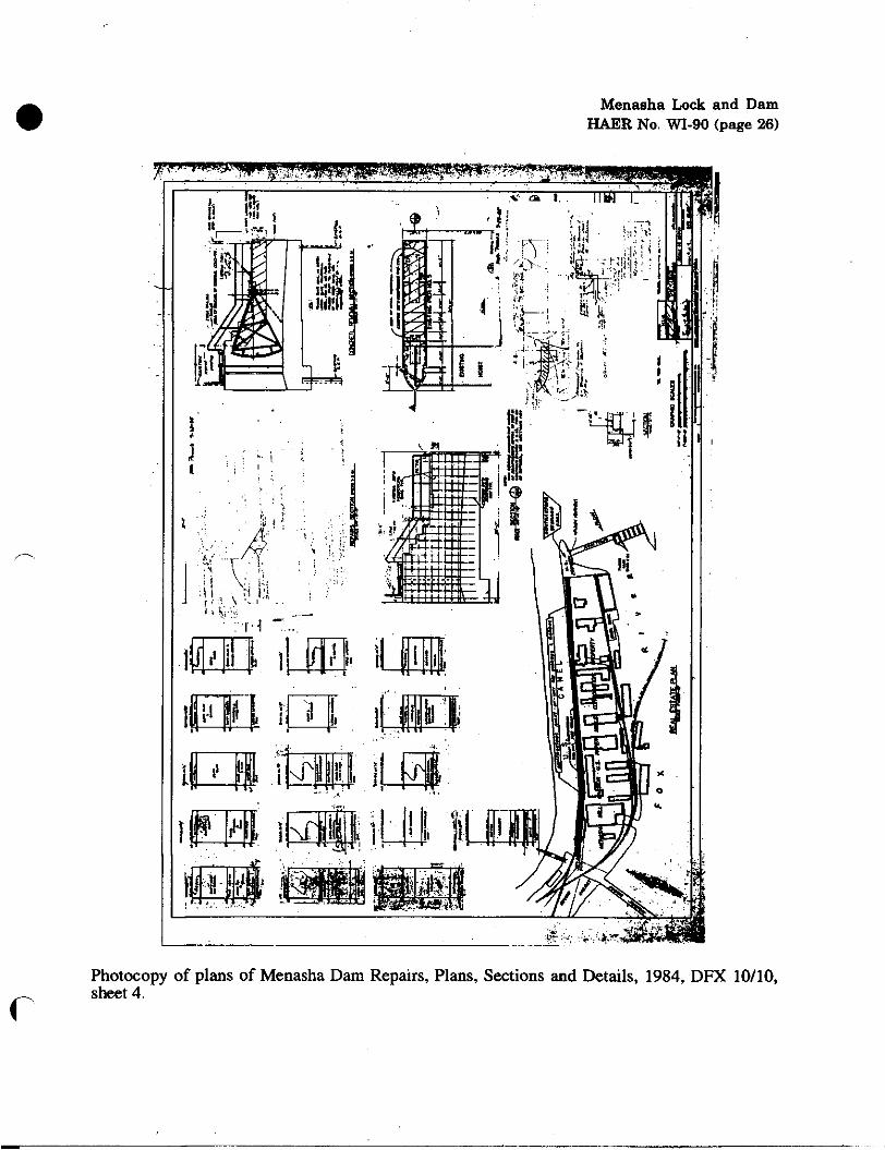
Photocopy of plans of Menasha Dam Repairs, Plans, Sections and Details, 1984, DFX 10/10, sheet 4.

Menasha Lock and Dam HAER No. WI-90 (page 27)
Photocopy of plans of Proposed Reconstruction, Menasha Dam, General Plan and Typical Sections, 1936, File #4-N-15.5, sheet 2.

Menasha Lock and Dam HAER No. WI-90 (page 28)
Photocopy of plans of Proposed Reconstruction, Menasha Dam, Sluiceway Plan and Typical Sections, 1936, File #4-N-15.5, sheet 3.

Menasha Lock and Dam HAER No. WI-90 (page 29)
Photocopy of plans of Proposed Reconstruction, Menasha Dam, Spillway Plan and Typical Sections, 1936, File no. 4-N-15.5, sheet 4.

Menasha Lock and Dam HAER No. WI-90 (page 30)
Photocopy of plans of Proposed Reconstruction, Menasha Dam, Steel Details, 1936, File no. 4-N- 15.5, sheet 5.

Menasha Lock and Dam HAER No. WI-90 (page 31)
Photocopy of plans of Proposed Reconstruction, Menasha Dam, Sluice Gate Hoist, 1936, File #4- N-15.5, sheet 6.

Menasha Lock and Dam HAER No. WI-90 (page 32)
—r-J 7—N
c Photocopy of plans of Menasha Dam Repairs, Plans, Location & Vicinity Maps, 1984, DFX 10/7, sheet 1.

Menasha Lock and Dam HAEB No. WI-90 (page 33)
Photocopy of plans of Menasha Dam Repairs, Plans, Sections and Details, 1984, DFX 10/9, sheet 3.

Menasha Lock and Dam HAER No. WI-90 (page 34)
-«■*■ f^.^-yr■;•:-■ -*-:.*r~,"r**- ^■•gt-*'--,"v-V*ir-,Sf.sa
Photocopy of plans of Menasha Dam Repairs, Survey Information, 1984, DFX 10/8, sheet 2.

Menasha Lock and Dam HAER No. WI-90 (page 35)
Photocopy of plans for Rehabilitation of Menasha Lock, Index of Drawings, Location and Vicinity Map, 1978, File #17-Ll-9, sheet 1.

Menasha Lock and Dam HAER No. WI-90 (page 36)
Photocopy of plans for Rehabilitation of Menasha Lock, Lock, Cofferdam and Site Plan, 1978, File #17-Ll-9, sheet 2.

Menasha Lock and Dam HAER No. WI-90 (page 37)
Photocopy of plans for Rehabilitation of Menasha Lock, Lock, Boring Logs, 1978, File #17-Ll-9, sheet 3.

Menasha Lock and Dam HAER No. WI-90 (page 38)
Photocopy of plans for Rehabilitation of Menasha Lock, Lock, Plan and Section, 1978 File #17- Ll-9, sheet 4.

Menasha Lock and Dam HAER No. WI-90 (page 39)
Photocopy of plans for Rehabilitation of Menasha Lock, Upper Gate Monolith, Plan and Sections, 1978, File #17-Ll-9, sheet 5.

Menasha Lock and Dam HAER No. WI-90 (page 40)
Photocopy of plans for Rehabilitation of Menasha Lock, Upper Gate Monolith, Sections, 1978, File #17-Ll-9, sheet 6.

Menasha Lock and Dam HAER No. WI-90 (page 41)
Photocopy of plans for Rehabilitation of Menasha Lock, Upper Gate Monolith, Sections and Details, 1978, File #17-Ll-9, sheet 7.

Menasha Lock and Dam HAER No. WI-90 (page 42)
Photocopy of plans for Rehabilitation of Menasha Lock, Upper Gate Monolith, Valve Details, 1978, File #17-Ll-9, sheet 8.

Menasha Lock and Dam HAER No. WI-90 (page 43)
%
'? :i
r
&
?;'
Photocopy of plans for Rehabilitation of Menasha Lock, Upper Gate Monolith, Valve Gear Mechanism Details, 1978, File #17-Ll-9, sheet 9.

Menasha Lock and Dam HAER No. WI-90 (page 44)
Photocopy of plans for Rehabilitation of Menasha Lock, Lower Gate Monolith, Plan and Sections, 1978, File #17-Ll-9, sheet 11.

Menasha Lock and Dam HAER No. WI-90 (page 45)
c Photocopy of plans for Rehabilitation of Menasha Lock, Lock Chamber and Misc., Sections and Details, 1978, File#17-Ll-9, sheet 10.

Menasha Lock and Dam HAER No. WI-90 (page 46)
Photocopy of plans for Rehabilitation of Menasha Lock, Lower Gate Monolith, Sections, 1978, File #17-Ll-9, sheet 12.

Menasha Lock and Dam HAER No. WI-90 (page 47)
111 "••{Hi,
SST-
1! so.
11:
Mi &■
1 Jl-'-hr
11A ^ **T
ii
fc4
ii. iii
■•'■ ■«■«•
iii t* Hi:
i*l!r
□ i: si
Photocopy of plans for Rehabilitation of Menasha Lock, Lower Gate Monolith, Sections and Details, 1978, File#17-Ll-9, sheet 13.

Menasha Lock and Dam HAER No. WI-90 (page 48)
Photocopy of plans for Rehabilitation of Menasha Lock, Stairs and Apron, Sections, 1978, File #17-Ll-9, sheet 14.

Menasha Lock and Dam HAER No. WI-90 (page 49)
si
j
6 I is.ii
i %'
c Photocopy of plans for Rehabilitation of Menasha Lock, Upper Miter Gate, Plan and Elevation, 1978, File #17-Ll-9, sheet 18.

Menasha Lock and Dam HAER No. WI-90 (page 50)
Photocopy of plans for Rehabilitation of Menasha Lock, Upper Miter Gate, Walkway and Girder I Details, 1978, File #17-Ll-9, sheet 19.

Menasha Lock and Dam HAER No. WI-90 (page 51)
r^
Photocopy of plans for Rehabilitation of Menasha Lock, Upper Miter Gate, Girder 4 and Seal Details, 1978, File #17-Ll-9, sheet 20.

Menasha Lock and Dam HAER No. WI-90 (page 52)
^N
Photocopy of plans for Rehabilitation of Menasha Lock, Upper Miter Gate, Quoin & Miter Girder Details, 1978, File #17-Ll-9, sheet 21.
Menasha Lock and Dam HAEft No. WI-90 (page 53)
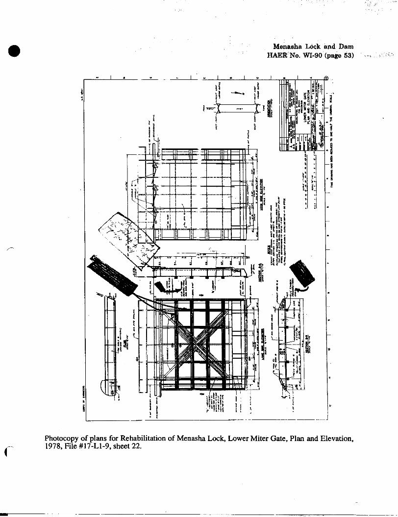
Photocopy of plans for Rehabilitation of Menasha Lock, Lower Miter Gate, Plan and Elevation, 1978, File #17-Ll-9, sheet 22.

Menasha Lock and Dam HAER No. WI-90 (page 54)
Photocopy of plans for Rehabilitation of Menasha Lock, Lower Miter Gate, Walkway and Girder 5 Details, 1978, File #17-Ll-9, sheet 23.

Menasha Lock and Dam HAER No. WI-90 (page 55)
Photocopy of plans for Rehabilitation of Menasha Lock, Lower Miter Gate, Quoin & Miter Girder Details, 1978, File #17-Ll-9, sheet 25.

Menasha Lock and Daro HAER No. WI-90 (page 56)
Photocopy of plans for Rehabilitation of Menasha Lock, Lower Miter Gate, Valve Details, 1978, File #17-Ll-9, sheet 26.

Menasha Lock and Dam HAER No. WI-90 (page 57)
Photocopy of plans for Rehabilitation of Menasha Lock, Lower Miter Gate, Valve Gear Mechanism Details, 1978, File #17-Ll-9, sheet 27.
Menasha Lock and Dam HAER No. WI-90 (page 58)
m *&
tfri
ilLl
i-
(
L
*:
:i
Hi
!i
s I 1 '/) i
% *
4
£ ^
"►
1
\Vl% n I
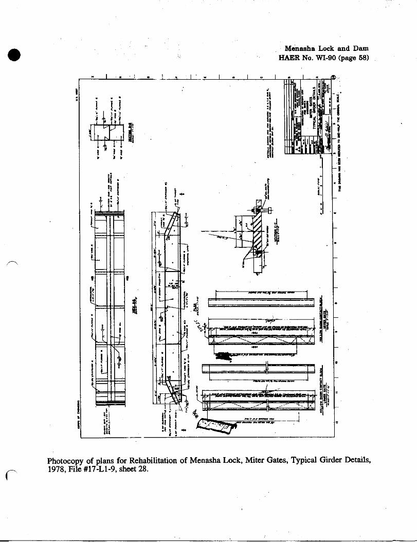
r Photocopy of plans for Rehabilitation of Menasha Lock, Miter Gates, Typical Girder Details, 1978, File #17-Ll-9, sheet 28.

Menasha Lock and Dam HAER No. WI-90 (page 59)
!i I
at, i
i
K
K *j f
.IP
Photocopy of plans for Rehabilitation of Menasha Lock, Miter Gates, Diagonals, 1978, File #17- Ll-9, sheet 29.

Menasha Lock and Dam HAER No. WI-90 (page 60)
* * * • ■■ i ■* ■
Photocopy of plans for Rehabilitation of Menasha Lock, Miter Gates, Miter Guide, 1978, File #17-Ll-9, sheet 30.
Menasha Lock and Dam HAER No. WI-90 (page 61)
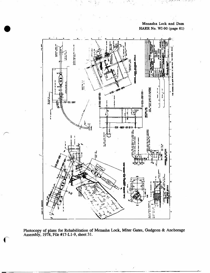
Photocopy of plans for Rehabilitation of Menasha Lock, Miter Gates, Gudgeon & Anchorage Assembly, 1978, File #17-Ll-9, sheet 31.

Menasha Lock and Dam HAER No. WI-90 (page 62)
Photocopy of plans for Rehabilitation of Menasha Lock, Miter Gates, Pintle Assembly & Lubrication Details, 1978, File #17-Ll-9, sheet 32.