memory management - harvard universitysites.fas.harvard.edu/~libe251/fall2019/slides/memory...
TRANSCRIPT

Memory ManagementProf. James L. Frankel
Harvard University
Version of 7:34 PM 2-Oct-2018Copyright © 2018, 2017, 2015 James L. Frankel. All rights reserved.

Memory Management
• Ideal memory• Large• Fast• Non-volatile (keeps state without power)
• Memory hierarchy• Extremely limited number of registers in CPU• Small amount of fast, expensive memory – caches• Lots of medium speed, medium price main memory• Terabytes of slow, cheap disk storage
• Memory manager handles the memory hierarchy
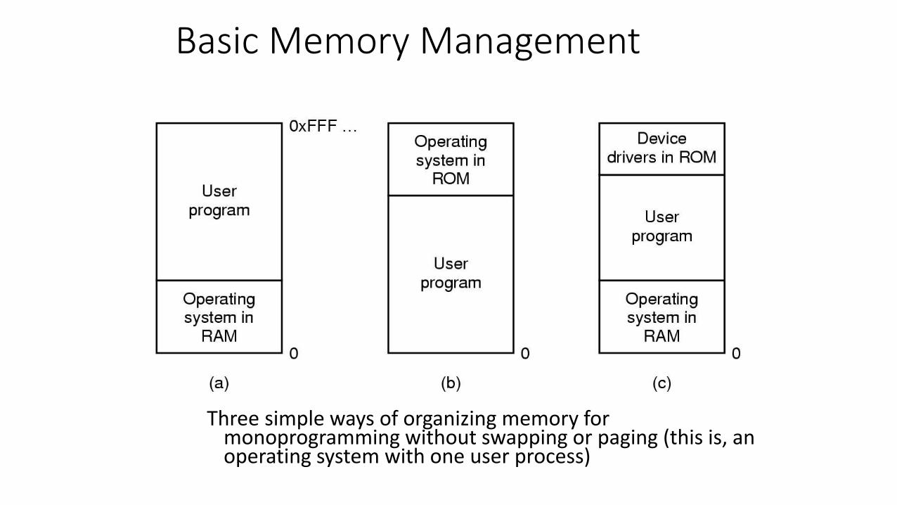
Basic Memory Management
Three simple ways of organizing memory for monoprogramming without swapping or paging (this is, an operating system with one user process)

Multiprogramming with Fixed Partitions
• Fixed memory partitions• separate input queues for each partition• single input queue

Probabilistic Model of Multiprocessing
• Each process is in CPU wait for fraction f of the time
• There are n processes with one processor
• If the processes are independent of each other, then the probability that all processes are in CPU wait is fn
• So, the probability that the CPU is busy is 1 – fn
• However, the processes are not independent• They are all competing for one processor
• More than one process may be using any one I/O device
• Better model would be constructed using queuing theory

Modeling Multiprogramming
CPU utilization as a function of number of processes in memory
Degree of multiprogramming

Analysis of Multiprogramming System Performance
• Arrival and work requirements of 4 jobs
• CPU utilization for 1 – 4 jobs with 80% I/O wait
• Sequence of events as jobs arrive and finish• note numbers show amout of CPU time jobs get in each interval
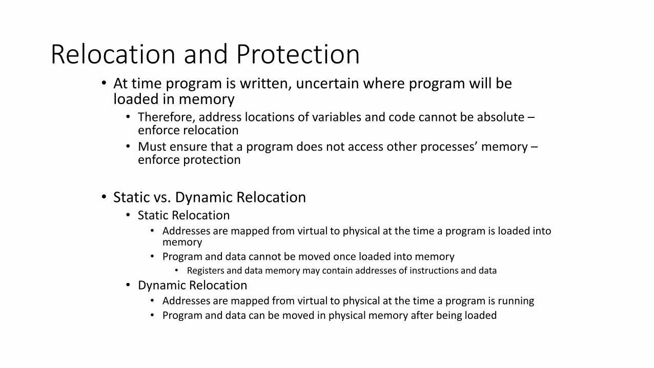
Relocation and Protection• At time program is written, uncertain where program will be
loaded in memory• Therefore, address locations of variables and code cannot be absolute –
enforce relocation• Must ensure that a program does not access other processes’ memory –
enforce protection
• Static vs. Dynamic Relocation• Static Relocation
• Addresses are mapped from virtual to physical at the time a program is loaded into memory
• Program and data cannot be moved once loaded into memory• Registers and data memory may contain addresses of instructions and data
• Dynamic Relocation• Addresses are mapped from virtual to physical at the time a program is running
• Program and data can be moved in physical memory after being loaded

Base and Limit Registers• The base register value is added to user’s virtual address
to map to a physical address – Relocation
• Virtual addresses greater than the limit register value is an erroneous memory address – Protection
• Allows only a single segment per process
• Does not allow a program to use more virtual address space than there is physical memory

Swapping
Memory allocation changes as• Processes are loaded into memory• Processes are swapped out of memory
Shaded regions are unused memory

Data Components
• Static Storage Class Variables• Either at block scope with the storage class designator static or at file scope• Default initial value of zero
• If initialized to zero, in BSS Segment• If initialized to a non-zero value, in Data Segment
• Lifetime is from program load time to program termination• Only one instance of each variable
• Automatic Storage Class Variables• No default initial value• Lifetime is from block entry to block exit• A new instance is created every time block is reentered• More than one instance may exist because a function may be called recursively• Stored on the stack
• Dynamic Memory• No initial value• Lifetime is from malloc to free• Stored in the heap
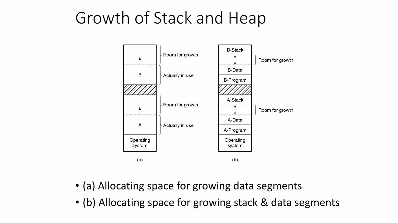
Growth of Stack and Heap
• (a) Allocating space for growing data segments
• (b) Allocating space for growing stack & data segments

Typical Memory Layout of a C Process

Memory Management with Bit Maps
• Part of memory with 5 processes, 3 holes• Tick marks show unit of allocation• Shaded regions are free
• Bit map stores information about which allocation-units are free or used
• Encapsulates the same information as a list

Memory Management with Linked Lists
Four neighbor combinations for the terminating process X
Shaded regions are free

Algorithms for Allocation
• First Fit
• Next Fit• Start search after previous allocation• Worse than first fit
• Best Fit• Find closest hole size• Creates many small holes
• Worst Fit
• Quick Fit• Maintain list(s) of useful-sized holes

Approaches to Virtual Memory (VM)
• Under user control – overlays
• VM uses fixed size pages
• Where is the instruction/data referred to by an address?• Some pages in memory
• Some pages on disk
• When a page is accessed that is not in memory, that causes a page fault
• Each process has its own page table – because each process has its own address space

Virtual Memory – Address Translation
The location and function of the MMU

Memory Management Unit (MMU)
• Translates• Virtual addresses (VA) for program and data memory into…
• Physical addresses (PA) for memory and I/O devices
MMUVirtual Address Physical Address

Page Table Function
The mapping fromvirtual memory addressesto physical memory addressesis given by the page table

Components of Addresses
• High-order bits of VA, the page number, used to index into the page table
• Low-order bits of VA, the offset, used to index within the page
• High-order bits of the PA is called the page frame number
• Low-order bits of the PA, the offset, is passed unaltered from the VA

Single-Level Page Table
Internal operation of an MMU with sixteen 4 KB pages and with eight 4 KB page frames

Two-Level Page Table
• 32 bit address with 2 page table fields
• Two-level page tables
Second-level page tables
Top-level
page table

Advantages of Two-Level Page Table (1 of 2)
• It does not use less memory for the page table if all virtual address space is utilized
• However, because the page table is allocated in chunks, if only portions of the virtual address space is utilized, significant savings may be garnered
• For example, imagine a 32-bit virtual address with 4K byte pages on a byte-addressable computer• In a single-level page table, the page table has 220 or 1,048,576 (1M) PTEs
• Gives the program a virtual address space of 232 bytes or 4G bytes
• Assuming each PTE is four bytes, that’s 4M bytes just for the page table

Advantages of Two-Level Page Table (2 of 2)
• Continuing with the assumptions of a 32-bit virtual address with 4K byte pages on a byte-addressable computer• In a two-level page table
• 10 bits for the top-level table and 10 bits for the second-level tables
• Assume there are four virtual address spaces used of 222 bytes each• Gives the program a virtual address space of 4 * 222 bytes or 16M bytes
• Requires four second-level page tables to be allocated
• The five page tables (i.e., the top-level page table and the four second-level page tables) have 5 * 210 entries• Assuming each PTE and each pointer to a PTE is four bytes, that’s 5 * 210 * 4 bytes or 20K
bytes for all the page tables

Page Table Entry (PTE)
Typical page table entry
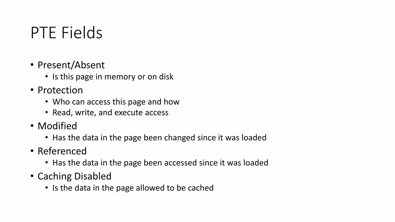
PTE Fields
• Present/Absent• Is this page in memory or on disk
• Protection• Who can access this page and how• Read, write, and execute access
• Modified• Has the data in the page been changed since it was loaded
• Referenced• Has the data in the page been accessed since it was loaded
• Caching Disabled• Is the data in the page allowed to be cached

Number of Memory Accesses
• The page tables reside in memory!• For each instruction that accesses only registers
• One access is required to read the PTE for the instruction address• One access is required to read the instruction
• For each instruction that accesses one data field in memory• One access is required to read the PTE for the instruction address• One access is required to read the instruction• One access is required to read the PTE for the data address• One access is required to read the data word
• And so forth for instructions that access more than one data field (if they exist)
• How can we reduce the number of memory accesses?

TLBs – Translation Lookaside Buffer
A TLB is a cache for the page table. The TLB speeds up address translation from virtual to physical.

TLB Function
• TLB implemented using a CAM (Content-Addressable Memory) also known of as an Associative Memory
• TLB faults can be handled by hardware or by software through a faulting mechanism (happens on SPARC, MIPS, HP PA)

TLB Schematic
Page Number
Page Number
Page Number
Page Number
Page Frame Number
Page Number
=
=
=
=
Virtual Address
Offset
Page Frame Number
Page Frame Number
Page Frame Number
Page Frame Number
Offset
TLB Hit
Physical Address
Segmentation
• Utilizing a range of addresses in memory that is referenced by• Segment number• Offset within the segment
• The segments’ boundaries are usually meaningful to the programmer• Module boundaries or Data segments• Different memory protection schemes
• Read only• Read-write• Execute
• May be the basis for virtual memory without paging• Entire segment is moved in and out of memory
• Or, may be layered on top of a paging system• A page table exists for each segment

Powers of Two
• 210 is 1K (Kilo)
• 220 is 1M (Mega)
• 230 is 1G (Giga)
• 240 is 1T (Tera)
• 250 is 1P (Peta)
• 260 is 1E (Exa)
• 270 is 1Y (Yotta)

Large 64-bit Address Space
• 12-bit offset (address per page)
• 52-bit page number given to the MMU
• Page Size• 12-bits implies 4K bytes/page for a byte addressable architecture
• Size of page table if all VAs are used• 252 or 4P PTEs
• That’s too many! Of course, we don’t have that much disk space either, but… We need an alternate way to map memory when address spaces get large

Inverted Page Table
• Organize Inverted Page Table by PAs rather than by VAs
• One PTE per page frame – rather than per virtual page
• However, now there is a need to search through the inverted page table for the virtual page number!• Obviously, this is very, very slow
• Many memory accesses per instruction or data access
• We rely on a large TLB to reduce the number of searches
• The inverted page table is often organized as a bucket hash table• Reduces the time to linearly search within a bucket

Inverted Page Table Comparison
Comparison of a traditional page table with an inverted page table

I-Space and D-Space
• Virtual memory and page tables are often split into Instruction and Data Spaces
• Can enhance the performance of both caches and page tables
• Both I- and D-Spaces that are currently being used should be mapped into memory• We don’t want accesses to data to cause program memory to be swapped out
• Behavior of I-Space• More sequential access• More locality of reference
• Loops• Functions calling functions
• Execute (read) only
Page Fault and Page Replacement Algorithms
• Page fault forces choice• Determine which page must be removed• Make room for incoming page
• Modified page must first be saved• Unmodified page is just overwritten• Pages with code are never modified
• Accessed page must be read into memory• Page table must be updated
• Better not to choose an often used page• Will probably need to be brought back in soon

Optimal Page Replacement Algorithm
• Replace page needed at the farthest point in future• Optimal but unrealizable
• Estimate future reference pattern• Log page use on previous runs of process
• Probably not reproducible
• Impractical
• Gives us a goal to attempt to attain

Not Recently Used (NRU) Page Replacement Algorithm
• Each PTE has Referenced & Modified bits• Both are cleared when pages are loaded
• Appropriate bit(s) set when page is referenced (read or written) and/or modified
• Periodically, the R bit is cleared
• Pages are classified• Class 0: Not referenced, not modified
• Class 1: Not referenced, modified
• Class 2: Referenced, not modified
• Class 3: Referenced, modified
• NRU removes page from lowest class at random
First-In, First-Out (FIFO) Page Replacement Algorithm
• Maintain a list of all pages• Ordered by when they came into memory: most recent at the
tail and the least recent at the head
• On page fault, page at head of list is replaced
• Disadvantage• Page in memory the longest may be used frequently

Second-Chance Page Replacement Algorithm
• Operation of a second chance• Pages sorted in FIFO order• R bit inspected before replacing the oldest page
• If R bit is set, the page is put at the tail of the list and the R bit is cleared
• Illustration above shows page list if fault occurs at time 20, and page A has its R bit set (the numbers above the pages are loading times)

The Clock Page Replacement Algorithm

Least Recently Used (LRU) Page Replacement Algorithm
• Good Approximation to Optimal
• Assume pages used recently will used again soon• Throw out page that has been unused for longest time
• Might keep a list of pages• Most recently used at front, least recently used at rear
• Must update this list on every memory reference!
• Alternatively, maintain a 64-bit instruction count• Counter incremented after each instruction
• Current counter value stored in PTE for page referenced
• Choose page whose PTE has the lowest counter value• Still requires a time-consuming search for lowest value
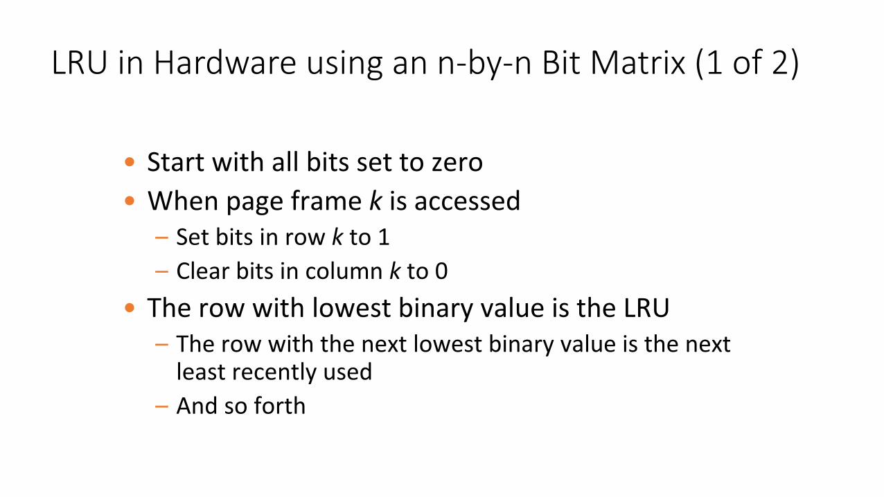
LRU in Hardware using an n-by-n Bit Matrix (1 of 2)
• Start with all bits set to zero
• When page frame k is accessed– Set bits in row k to 1
– Clear bits in column k to 0
• The row with lowest binary value is the LRU– The row with the next lowest binary value is the next
least recently used
– And so forth
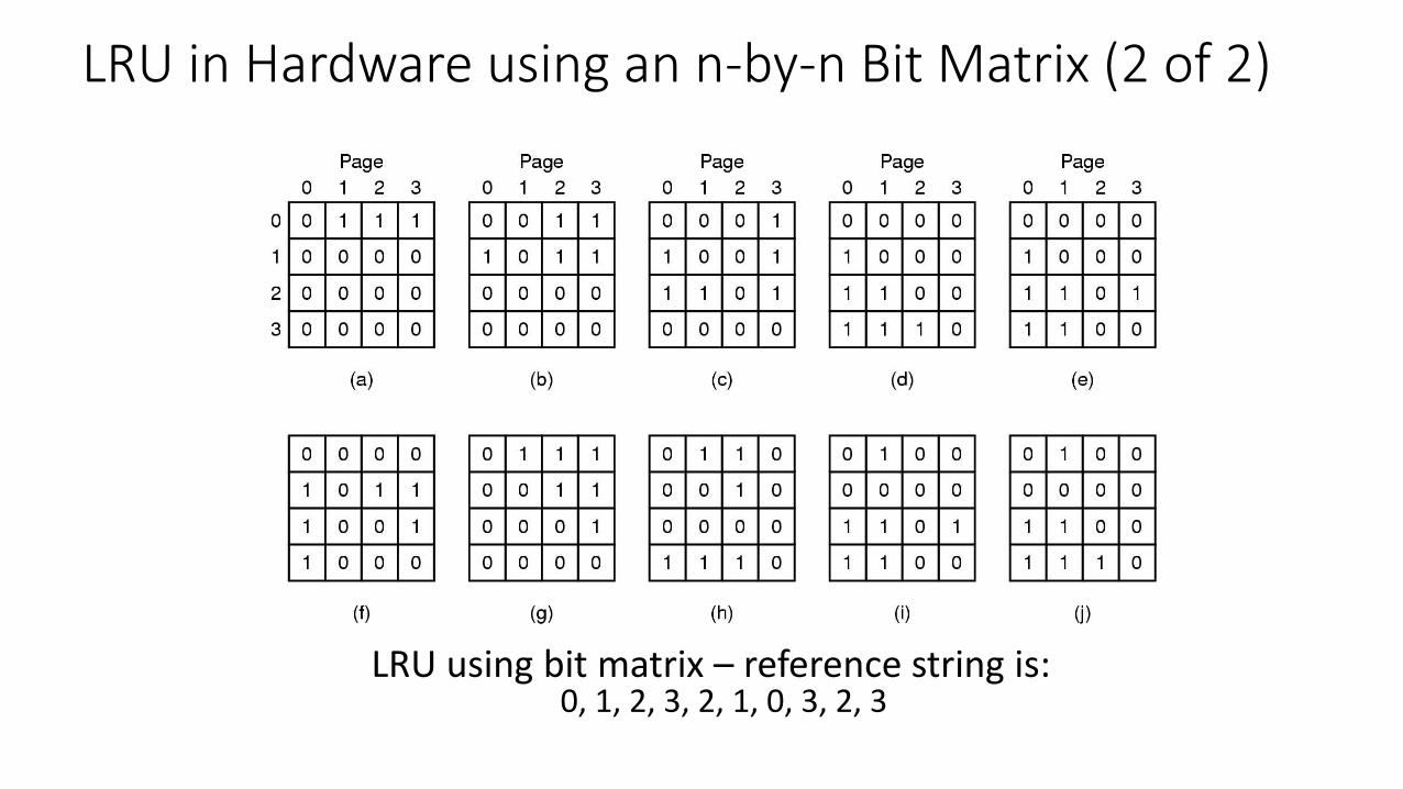
LRU in Hardware using an n-by-n Bit Matrix (2 of 2)
LRU using bit matrix – reference string is:0, 1, 2, 3, 2, 1, 0, 3, 2, 3

• A simulation of LRU in Software
• Associate a counter with each page
• Initialize all counters to zero
• On occasional clock interrupts, examine the R bit for each page in memory• Add one to the counter for a page if its R bit is set
• Choose page with lowest counter value for replacement
• Problem: frequently accessed pages continue to have large values – i.e., counters are never reset• Fix: (1) Shift all counters right on clock interrupt• (2) Set MSB if R bit is set
Not Frequently Used (NFU) Page Replacement Algorithm (1 of 2)

• The aging algorithm simulates LRU in software
Not Frequently Used (NFU) Page Replacement Algorithm (2 of 2)
00010000

The Working Set Page Replacement Algorithm (1 of 2)
• The working set is the set of pages used by the k most recent memory references
• w(k, t) is the size of the working set at time, t
k

The Working Set Page Replacement Algorithm (2 of 2)
The working set algorithm

The WSClock Page Replacement Algorithm (1 of 2)
• Circular list of page frames – Initially empty
• Associate a time of last use, R bit, and M bit with each page
• On page fault, examine the R bit for page pointed to by clock hand– If its R bit is set, clear the R bit and move hand to next page
– If its R bit is clear, and if its age is less than or equal to τ, advance the hand
– If its R bit is clear, and if its age is greater than τ and it is not modified, replace that page
– If its R bit is clear, and if its age is greater than τ and it is modified, schedule a write of that page to disk and advance the hand and examine the next page

The WSClock Page Replacement Algorithm (2 of 2)
Operation of the WSClock algorithm

Review of Page Replacement Algorithms

Adding Page Frames
• In general, adding more page frames decreases the number of page faults, but…
• Belady’s Anomaly shows that this is not always true
• Stack Algorithms do work better with more page frames
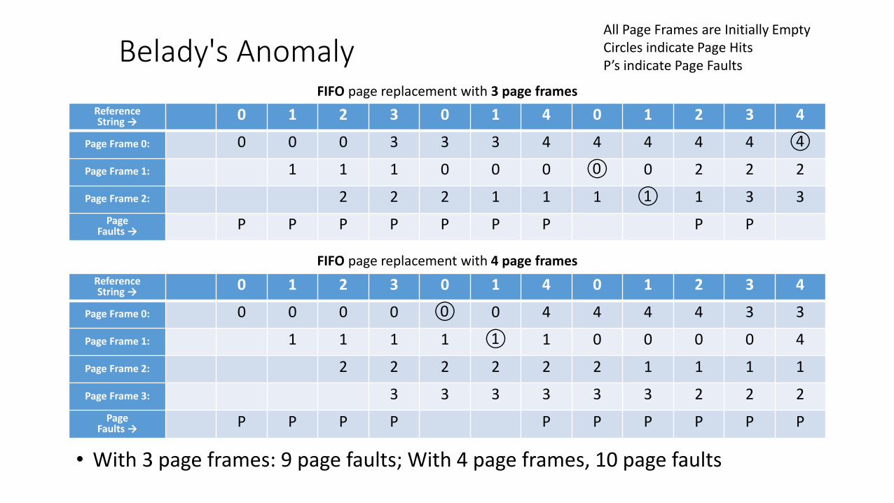
Belady's Anomaly
• With 3 page frames: 9 page faults; With 4 page frames, 10 page faults
All Page Frames are Initially EmptyCircles indicate Page HitsP’s indicate Page Faults
FIFO page replacement with 3 page frames
FIFO page replacement with 4 page frames
ReferenceString → 0 1 2 3 0 1 4 0 1 2 3 4
Page Frame 0: 0 0 0 3 3 3 4 4 4 4 4 ④
Page Frame 1: 1 1 1 0 0 0 ⓪ 0 2 2 2
Page Frame 2: 2 2 2 1 1 1 ① 1 3 3
PageFaults → P P P P P P P P P
ReferenceString → 0 1 2 3 0 1 4 0 1 2 3 4
Page Frame 0: 0 0 0 0 ⓪ 0 4 4 4 4 3 3
Page Frame 1: 1 1 1 1 ① 1 0 0 0 0 4
Page Frame 2: 2 2 2 2 2 2 1 1 1 1
Page Frame 3: 3 3 3 3 3 3 2 2 2
PageFaults → P P P P P P P P P P