membrane technology against climate change in …membrane technology against climate change in the...
TRANSCRIPT

Membrane Technology against Climate Change in the 21st century
Science Council of JapanWater Symposium
“Sustainable Water Resources Management in Asia” Feb. 27, 2009
Prof. Chung-Hak Lee,
School of Chemical and Biological Engineering, Seoul National University, KOREA

Global warmingGlobal warming
- Carbon dioxide and other gases: trapping solar heat in the atmosphere warming the surface of the planet
- The numerous scientists agree reality of global warming: Glaciers are melting, plants and animals are being forced from their habitat,
Source: USEPA
plants and animals are being forced from their habitat, and the number of severe storms and droughts is increasing.

The glacier of the north pole
The symptoms of climate changes in the Korean Peninsula
Since last 100 years,
The average temperature of the earth increased by 0.74 ℃
, whereas the average temperature of the Korean Peninsular increased by 1.5 ℃(double)

The symptoms of climate changes in the Korean Peninsula
The sea level around the Jeju island increased by 22cm since last 40 years.
Winter has been shortened by one month, summer has been extended by 20 days after 1920s
Heavy rainfall : 2.8 days per year (an average year; 2.0 day) since last 10 years
Extreme Heat caused the death toll of 2,127 death since last 10 yearsMalaria caused 2,227 deaths in the year of 2007

The symptoms of climate changes in the Korean Peninsula
The end of 21st century (the basic years: 1971-2000)Temperature: 4℃ increase, Rainfall: 17% increase
2071 - 2100At the end of 21st centuryA subtropical zone 2071 - 2100
: A subtropical climateA subtropical zonewill move northward
Sea level rising (1m) in 2100Submersion area: 2,500 km2
2.6 % of Korean population (1.25 million people)will difficult in livelihood The basic years (1971 - 2000)

Global warmingGlobal warming
- Carbon dioxide and other gases: trapping solar heat in the atmosphere warming the surface of the planet
- The numerous scientists agree reality of global warming: the number of severe storms and droughts is increasing.
Source: USEPA
the number of severe storms and droughts is increasing.

National Project: Restoration of 4 Main Rivers( Han, Nakdong, Keum, Youngsan Rivers)
2008 2012

National Project: Restoration of 4 Main Rivers
Objectives: i) Flood control, ii) Improvement of river water quality,iii) Provision for water shortage, iv) a relief measure for the unemployed.
Period : 2009~2012 ( 4 years)
2008 2012
Total Working Expenses : 10 billion $* Annual flood damage: 2 billion $

The life cycle of water qualityQ
ualit
y of
Wat
er
Source
Usage
Water Reuse
• Agricultural : 74%• Municipal : 14%• Industrial : 12%
Surface / Ground water : 3%
(Global market 2005~2015,IDA report)
: Core business segment
• Advanced WWT• Reuse Treatment
• Conventional WWT*
• Desalination• Water Treatment
-Advanced wastewater treatment and reuse & Seawater desalination:two of the most sustainable ways to create alternative water source
- Membrane Technology : Key for these treatment processes.
Qua
lity
of W
ater
Source
Wastewater Effluent
Time Sequence
• Surface / Ground water : 3%• Seawater : 97%
• Conventional WWT*
*Courtesy of Doosan heavy Industries and construction Co.

Fresh Water 2.5 %(35 M km3)
Glacier 1.76 %Groundwater 0.76 %Lakes & Rivers 0.0067 %
Salt Water 97.5 %(1,351 M km3)
Sea Water 96.5 %GroundwaterLakes
World Water Resources
Source : Water in crisis (Source : Water in crisis (GloickGloick, P.H., 1993), P.H., 1993)
Lakes & Rivers 0.0067 %Others 0.0019 %
Seawater Desalination is the key to solve water shortage!!

Total capacity of world wide seawater desalination plants : > 30 million tons/dayTotal capacity of world wide seawater desalination plants : > 30 million tons/day Total market growth rate : ~11%/year Total market growth rate : ~11%/year (SWRO: ~17%/year)(SWRO: ~17%/year)
International Market TrendsInternational Market Trends
Europe
= 1million m3/day (220MIGD)
North America
Central America
South AmericaAustralia
AsiaMiddle East (50%)
Africa
Source: Wangnick (2004)

1000
Market possession capacity (Source: IDA 2001~2005)Market possession capacity (Source: IDA 2001~2005)
Technology turning point = NOW Korean Group (Korean Group (DoosanDoosan) leads MSF () leads MSF (Multi Stage FlashingMulti Stage Flashing) plant technologies ) plant technologies
all around the world. all around the world. But, market needs is being moved to membraneBut, market needs is being moved to membrane--based desalination.based desalination.
Market TrendsMarket Trends
0
200
400
600
800
1000
Doo
san
GE
Ioni
csFi
sia
Italim
pian
tiV
WS
Side
mM
HI/S
asak
ura
VW
S W
estg
arth
Hita
chi Z
osen
Deg
rem
ont
Kur
itaN
omur
aB
iwat
er A
EWT
Envi
roge
nics
Sa
saku
raG
eida IH
IU
nkno
wn
Siem
ens W
ater
(USF
)V
WS
Met
ito A
rabi
aH
ydra
naut
ics
IDE
Mits
uiV
A T
ECH
MH
IA
nsal
doV
WS
Entro
pie
AES
Cad
agua
Mits
ui/S
asak
ura/
MH
IPr
euss
agEM
CO
Million m3/d

HP Pump
Chlorine feed
Seawater Feed
Dirty Water Blow Off
Permeated
Tank
LP Pump
Cartridge
FilterSulphuric Acid feed
Coagulant feed
Air Blower
SBS feed
RO (REVERSE OSMOSIS)
Seawater Desalination Technologies
Brine Blow Off
Tank
To Remineralization Plant
HYBRID (MSF+RO / MED+RO)
Hybrid Desalination & Power Plant, UAE
RO building area, UAE
*Courtesy of Doosan heavy Industries and construction Co.

Prevention of membrane failure- Tensile Strength : >25kgf/fil- Peeling Strength : >1Mpa
Optimization of separate aerator& easy expansion of capacity by stacking horizontal module
HorizontalConfiguration
HorizontalConfiguration
Wetting -free
Wetting -free
Easy Storage & delivery
HighPeelingStrength
HighPeelingStrength
Maximization of Durability Low EnergyEasy Handling
Membranes for 21st Century
OptimizedAeration
OptimizedAeration
Excellent peeling strengthWetting-free characteristics
Low energy system
HighTensile
Strength
HighTensile
Strength
StrengthStrength
* Courtesy of KOLON Industries, Inc.

Odor Organics
Algal metabolites Halogenoanisoles Halogenophenols
Nanofiltration Membrane for multiful purposes- Removal of natural organic substance & odor organics
in municipal water treatment.- Water softening- Double pass Sea Water desalination
O
C l
C l
C l
2,4,6-trichloroanisole (80pg/L)
O
B r
B r
B r
2,4,6-tribromoanisole (20pg/L)
O H
C l
2-chlorophenol (88ng/L)
2,6-dibromophenol (16ng/L)
B r
B r
O H
Geosmin (4ng/L)
O H
O H
2-Methylisoborneol (2-MIB) (9ng/L)
* Courtesy of Woongin Chemical

SeaHERO R&D program S
Supported by Ministry of Land, Transport and Maritime Affairs (MLTM)
* Courtesy of Prof. I.S. Kim at KGIST
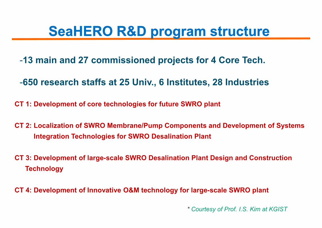
SeaHERO R&D program structureSeaHERO R&D program structure
CT 1: Development of core technologies for future SWRO plant
-13 main and 27 commissioned projects for 4 Core Tech.
-650 research staffs at 25 Univ., 6 Institutes, 28 Industries
CT 2: Localization of SWRO Membrane/Pump Components and Development of Systems Integration Technologies for SWRO Desalination Plant
CT 3: Development of large-scale SWRO Desalination Plant Design and Construction Technology
CT 4: Development of Innovative O&M technology for large-scale SWRO plant
* Courtesy of Prof. I.S. Kim at KGIST

1. Membrane Operation Mode
Membrane Technology for Green Growth- less energy & chemicals -
1. Membrane Operation Mode
2. Less Biofouling: Microscopic Approach
3. Preparation of New Functional Membranes

1.1. Turning Point of Membrane Operation ModeTurning Point of Membrane Operation Modefor less energy consumptionfor less energy consumption
side stream submerged
Kazuo Yamamoto et al. (1989), Water Science and Technology, 21, 43-54
Citation Number (Feb. 2009) : 233

“Biofilm”
Main obstacle in Main obstacle in
Reverse osmosis(RO)/ Nanofiltration(NF)
RO/NF permeateWastewater feed
Microfiltration(MF)/ Ultrafiltration(UF)
Activated sludge
MBR permeate
Wastewater reclamationand reusing
2. Less Biofouling : from Macroscopic to Microscopic Approach
Permeate
membrane surface Decrease of water flux
Main obstacle in Main obstacle in a membrane processa membrane process
-- Formation of Biofilm Formation of Biofilm --
Low water flux : 10~20 L/mLow water flux : 10~20 L/m22/h/h
Short membrane life span : 3Short membrane life span : 3--5 yr5 yr
High energy consumption : 0.3~0.6 kWh/mHigh energy consumption : 0.3~0.6 kWh/m33
High installation High installation & &
operating costoperating cost
Activated sludgereactor
MBR

ETET BTBT+
2. Less Biofouling: Microscopic Approach
In-Soung Chang and Chung-Hak Lee, Desalination, Vol.120, 221-233, 1998
Citation Number (Feb. 2009) : 158
Microbial PhysiologyMacroscopic MBR
“Effect of physiological states of activated sludge on membrane fouling”

MBR for Green Growth
FusionBT IT
2. No Biofouling (ultimate goal): Quorum Sensing
Molecular biologyMolecular biology
BT ITImage
analysis
ET
+
Current MBR
porosity, Biovolume,Cluster size
CLSM, FISH,PCR-DGGE,
Quorum sensing
Bio-cake analysis:
NT+ Nano
materials

Quorum Sensing ?
Symbiosis
Virulence
Competence
Conjugation
Group behaviorMicrobial community
: Signal molecules (autoinducer)
Antibiotic production
Motility
Sporulation
Biofilm formation
: Bacteria

BiofilmMembrane
Quorum sensing based biofouling control in MBR : Concept
• Low flux• High energy• Short life-span
Molecular level(Destruction of autoinducer)
Micro-scale(membrane-biofilm)
Engineering system(Uproot of Biofouling)
• High flux• Low energy• Long life-span

AHL QS activity in MBR : Experiment scheme
Biofilm
1. Take out
3~4 cm
2. Disintegration 3. Bioassay for AHL detection
Indicating agar
MBR
Hollow fiber membrane

50
60
70
80
TMP
(kPa
) 50
60
70
80
TMP
(kPa
) 50
60
70
80
TMP
(kP
a)
C8-HSL(1ppm)
Control
C8-HSL (1ppm) + Acylase (10 ppm)
Biofouling prevention by quorum quenching
0
10
20
30
40
0 500 1000 1500Operation time (Minutes)
TMP
(kPa
)
0
10
20
30
40
0 500 1000 1500Operation time (Minutes)
TMP
(kPa
)
0
10
20
30
40
0 500 1000 1500Operation time (Minutes)
TMP
(kP
a)
Acylase(10 ppm)

Loss of soluble acylase in continuous MBRs
Wastewater 1) Effluent
: Active Enzyme
: Inactive Enzyme : Activated sludge
3) Sludge withdrawn
2) Inactivation

Effect of MEC on MBR performance: TMP profile
MEC: Magnetic Enzyme Carrier

Fabrication of new functional membranes(capillary force lithography)
3. New Functional Membranes
(capillary force lithography)

Fabrication of new functional membranes(capillary force lithography)
Solvent evaporation
E-beam lithography
Capillary force lithography
PDMS mold
Si SiPDMS mold
Replica moldMaster mold
Supporting layer (Polysulfone)
Guard wall
PVDF solution
Solvent adsorption
PDMS moldPatterned PVDF membrane

Advantages of patterned membrane
1
• Decrease in contact area
• Sloughing is easily induced• Acting like a spacer. • Increase in surface area
SpacerSloughing Effective area
2 3
Induced flow
Cross-flow
Induced flow
Membrane

Advantages of patterned membrane
(a) NF (b) MF
Figure. SEM images of patterned PVDF skin layer for
(a) NF, (b) MF (top view)

East Asia
NGO Central Government
Global
National Green Governance
Regional Green Governance in AsiaRegional/Global
Green Governance
Civil Society
Individual Company
Local Government
Local Green Governance

i) MEDINA (Desalination, )
EU Projects for the next generation membrane technology
- Green Lead Markets in Asia as well as in Europe
ii)ii) EUROMBRA EUROMBRA ((MBRMBR, 10 , 10 countries )countries )
iii)iii) AMEDEUS AMEDEUS ((MBRMBR, 6 , 6 countries )countries )
iv)iv) MBRMBR--TRAIN TRAIN ((MBRMBR, 7 , 7 countries )countries )
v) PURATRET v) PURATRET ((MBRMBR, 10 , 10 countries )countries )

First Announcement and Call for PostersFinal MBR-Network Workshop
“Salient outcomes of the European R&D projects on MBR technology“
Sponsored By:
Organised By:
on MBR technology“
Berlin, Germany
Abstract submission: [email protected]: 30 September 2008
31 March – 1 April 2009
Hosted by Trade Fair « Wasser Berlin 2009 »Hosted By:
www.MBR-Network.eu
Spe
cial
ised
C
onfe
renc
e

AMBITIONAsian Membrane Bioreactor Initiative
by Trilateral cooperatION
21st Membrane Tech
Asian Green Governance with Membrane Technology
Presently available MBREurope
North America East AsiaMitsubishi R., Toray, Kubota, Shanghais YFT, KEC, Genbr,
KMS
Upgrading
AMEDEUS
Siemens
GE-Zenon

AcknowledgementsAcknowledgements
http://wemt.snu.ac.krhttp://wemt.snu.ac.kr
Prof. Chung-Hak Lee
WATER ENVIRONMENT – MEMBRANE TECHNOLOGY Lab.SCHOOL OF CHEMICAL AND BIOLOGICAL ENGINEERING,SEOUL NATIONAL UNIVERSITY, Korea

Global Water Shortage in 2025Global Water Shortage in 2025
- Water shortage population: 1.1 billions in 2005 and 3 billions in 2025. - WHO reports that 3.4 million per year are killed by waterborne diseases. (2005)
Very high stress
High stress
Mid stress
No stress
No dataSource : International water management institute

Market needs is being moved to SWRO Market needs is being moved to SWRO SWRO market is rapidly growing.SWRO market is rapidly growing.
Total55
33
Market GrowthMarket Growth
Source : GWI Desalination markets 2005~2015/ IDA 19th Inventory
SWRO
O & M
2005
12
22.6
6
13.6
33
1.33
8
(Unit: 1011 KRW)
2007-2011 2012-2020

Key Research Issues UltraUltra--precision seawater analysis techniquesprecision seawater analysis techniques(Ex: Removal of salt inhibition on the analysis, lowering the detection limit, etc)(Ex: Removal of salt inhibition on the analysis, lowering the detection limit, etc)
System Engineering for largeSystem Engineering for large--scale unit train (scale unit train (8MIGD8MIGD))(Ex: Reliability in System design and operation for the large(Ex: Reliability in System design and operation for the large--scale unit train, scale unit train, Optimization of energy recovery, Development of energy saving system, etc)Optimization of energy recovery, Development of energy saving system, etc)
Increase of recovery ratio (Increase of recovery ratio (60%60%))(Ex: Selective Removal of Ca(Ex: Selective Removal of Ca2+2+ and Mgand Mg2+2+ ions by pretreatment, innovative SWRO ions by pretreatment, innovative SWRO system design, etc)system design, etc)
Innovative SWRO membrane modulesInnovative SWRO membrane modules(Ex: Higher water permeability, Higher salt rejection (99.8% (Ex: Higher water permeability, Higher salt rejection (99.8% 99.9%99.9%)), Higher Boron , Higher Boron removal(90% removal(90% 96%96%)), Chemical and fouling endurances, scale, Chemical and fouling endurances, scale--up of the module (up of the module (16 16 inchesinches),), etc)etc)
* Courtesy of Prof. I.S. Kim at KGIST

Engineering Material Chemical Biological
BiofilmBiofilm
2. Less Biofouling: Microscopic Approach
Engineeringapproaches
• Critical flux
• Module design
• Hydrodynamics
Materialapproaches
• New material
• Membrane modification
Chemicalapproaches
• Chemical additives
• Activated carbon
Biologicalapproaches
• Analysis of biofilm
• SRT, DO
New ParadigmNew Paradigm : How to : How to essentiallyessentially prevent biofouling prevent biofouling by uprooting the bby uprooting the biofilmiofilm formation ?formation ?

A.tumefaciens A135 bioassay for AHL detection
AHL autoinducer
Sample
Diffusion
Indicating agar(A.tumefaceins A136, LB agar, Antibiotics, X-gal)
Filter(0.45 micron)
AHL autoinducer
Vertical view
AHL autoinducer (Yes)
Top view
Blue color development around the sample
Sample
Filter
Indicating agar
AHL autoinducer (No)

60
80
100
TMP
(kP
a)
1st batch 2nd batch 3rd batch
Magnetic Enzyme Carrier vs. Soluble Acylase
0
20
40
0 10 20 30 40 50 60 70
Time (hrs)
TMP
(kP
a)
Control Soluble enzyme MEC

Manufacturing Process for Patterned Membranes
Guard-WallPDMS mold
Weight(additional pressure)
Vacuum
SolventEvaporation
SolventAdsorption
• Cast PVDF solution on the Supporting layer
• Cover with PDMS mold
• Additional pressure is applied
• Control the vacuum and temperature
Supporting Layer (Polysulfone)PVDF Solution
(PVDF + DMF)
Vacuum