melt flow indexer - home - aml instruments · pdf filemfi 4050 manual issue b feb 2014 melt...
TRANSCRIPT
MFI 4050 Manual Issue B Feb 2014
MELT FLOW INDEXER
MODEL MFI 4050
OPERATING MANUAL
Rhopoint Instruments Ltd Rhopoint House Enviro 21 Park
Queensway Avenue South St Leonards on Sea
TN38 9AG UK
Tel. No. +44 (0)1424 739623 Fax No. +44 (0)124 730600
www.hanatekinstruments.com

MFI 4050
2
INTRODUCTION TO MELT FLOW MEASUREMENT MELT MASS-FLOW RATE AND MELT VOLUME-FLOW RATE The measured flow of a thermoplastic material through a die following specified conditions of length, diameter, temperature and pressure is known as either its Melt Mass-Flow Rate (MFR) or Melt Volume-Flow Rate (MVR). Differing standard conditions of extrusion temperatures and pressures are used for the varying polymer types, however, for comparison purposes different samples of the same polymer should be tested under identical conditions. The MFR/MVR apparatus should be regarded as a simple rheometer operating at conditions of low shear. Although the applied shear stresses and the resultant shear rates are very much lower than those utilised in most processes, the results obtained do provide useful data and an indication as to the relative ease with which the materials will flow when processed. Should a process require a relatively high rate of shear, (typically injection moulding) then a polymer of high MFR/MVR is generally selected as this is an indication of easier flow than one of low MFR/MVR. The MFR/MVR is also a measure of the molecular weight of a sample and is, therefore, indicative of the mechanical strength of the material. Average molecular weight and MFR/MVR are indirectly proportional, so that although a sample will process more readily, its strength and resistance to stress is likely to be poor. The Melt Flow Indexer has other test uses i.e. by performing the MFR/MVR test under two or more differing loads, the useful data on the rheological properties of the material can be determined. A useful measure of the shear stress/shear rate relationship can be made by measuring the samples MFR/MVR at the standard and at the higher load. Increasing the test load (for polythene’s) from the standard 2.16 kgs to 21.6 kgs increases the level of shear rate by a factor between 50 and 100:1, depending on the MWD of the sample and the arithmetic ratio: MFR 21.6 kgs/MFR 2.16 kgs gives a measure of flow parameters. Depending on the MFR at 2.16kg load, the value at 21.6kg load can be equivalent to the shear rates of more than 100 secs-1 coming possibly into the range of extrusion processes. The facility also exists to measure flow parameters at different temperatures, giving an insight as to the temperature sensitivity of the sample. It is wrongly assumed that two polymer samples having the same MFR/MVR will behave in the same way with respect to output (shear rate) when tested under the same set of conditions. They could, however, behave quite differently when
MFI 4050
3
subjected to higher pressure (shear stress) as required for moulding or extrusion process. Should the samples have differing MOLECULAR WEIGHT DISTRIBUTIONS (MWD) the increase in shear stress will differ as well. Generally speaking, a larger MWD corresponds with greater shear sensitivity, i.e. a higher rate of change in shear rate per unit increase in shear stress. Further information available from Melt Indexers are the measurement of “Die Swell” and “Drawdown”. Die Swell is the arithmetic ratio between the cooled extrudate at ambient temperature and the die diameter. Drawdown is the extending of the polymer extrudate by its own weight as it is extruded. Both these factors provide useful information for the blow Moulding Industry.

MFI 4050
4
THE HANATEK MELT FLOW INDEXER The HANATEK Melt Flow Indexer has been designed in accordance with ISO 1133, ASTM D1238 (Part A, B & C), BS 2782, ASTM 3364 The unit comprises a cylindrical barrel with a precise honed bore of 9.55mm diameter. The barrel is fully insulated minimising heat transfer from barrel to casing. The barrel is heated by three differing wattage heater elements, each with independent temperature control and a PT100 sensor. This enables temperature stability to be reached within approximately 15 minutes and the total barrel length to be controlled to + / - 0.2 deg. C. The HANATEK piston is made of solid steel and built precisely to the standard. The insulting sleeve and piston together are tarred to precisely 130gms. If weights above 10kgs are required to be used then the optional weight guide system should be purchased and utilised. HANATEK dies are made from tungsten carbide and are built precisely to the standard. The standard die has a polished bore measuring 2.0955mm. Further dies including ½ size dies are available on request.

MFI 4050
5
WARNING
DURING SET UP, TESTING AND CLEANING THE HANATEK MFI HAS HOT AREAS AROUND THE BARREL THAT CONSTITUTE BURNING HAZARDS- CARE SHOULD BE TAKEN AT ALL TIMES. SUITABLE PROTECTIVE EYEWEAR/CLOTHING/HEATPROOF GLOVES SHOULD BE WORN WHERE NECESSARY. CARE SHOULD ALSO BE TAKEN WHEN HANDLING WEIGHTS
ASSEMBLY
1. Unpack the unit carefully and check the contents against the packing list. 2. Place the instrument on a suitable sturdy bench- AWAY FROM STRONG
DRAUGHTS 3. Ensure the instrument is level before use.
Use the included bulls’ eye spirit level and adjust the feet until the spirit level bubble remains central. This is important and must be periodically checked and adjusted every time the equipment is moved.
4. Plug the mains power cable into the socket on the rear of the instrument.
5. Attach the airline to the air connector on the rear of the instrument. Note the air supply should be filtered compressed air, lubricated or un-lubricated and should not exceed 6bar.

MFI 4050
6
6. Adjust the pressure to 5bar using the control knob on the side of the
instrument
7. Plug the temperature probe into the instrument and place the probe in the holder.

MFI 4050
7
SET UP 1.0 Check the barrel, piston, die and weights are clean and undamaged
before use. DAMAGED DIES MUST BE REPLACED IMMEDIATELY- THIS ENSURES CONSISTENT TEST RESULTS THAT COMPLY WITH THE RELEVANT STANDARDS.
2.0 Ensure the die retaining slide plate is in position.
3.0 Place the die in the barrel.
The die and die retaining slide in position- ready to begin testing.
4.0 Place the test weight on to lift mechanism. Lift the displacement sensor is
attached to the weight.

MFI 4050
8
Power UP
1.0 Power up the instrument by switching on the red mains power buttons at the rear of the instrument. Then press and hold the round push button at the side of the instrument until the screen turns on.
2.0 Touch the screen to continue.
3.0 The instrument displays serial number the date it was last certified and firmware details. It is recommended that the instrument is calibrated annually to ensure all tests made are within the relevant standard. If the instrument has not been calibrated within the last 12 months a reminder screen will be displayed.
Calibration Reminder screen

MFI 4050
9
Test Selection
4.0 Before proceeding to the test menus, the operator should check the
options. This is where the die type and test weight are selected. The instrument is pre-set for the standard test conditions- 2.16 KG weight and 2.0950mm die. There are also 2 check box options, Lift operated and Temperature verification.
Temperature Verification Selecting this option will prompt the user to verify the temperature of the barrel with the probe before commencing every test.

MFI 4050
10
5.0 Test selection screen
Standard Test The Standard test should be used for any material where the exact melt density is known. This test calculates MFI, MVF, Shear Stress and Shear Rate. Cut-Off Test The cut off test should be used for any material where the exact melt density is unknown; this test calculates the material MD in addition to MFI, MVF, Shear Stress and Shear Rate. The test involves manually cutting the extrudate and weighing on an accurate balance. Once the melt density is known, the standard test can be used- this has further options for shorter tests and slice tests where inconsistencies (bubbles) in the tested polymer are removed from overall calculations. The test is fully automated and requires no operator interaction. Test Set up Screen
This screen allows the user to set the parameters for the MFI test.
Standard Test Cut Off Test

MFI 4050
11
Temperature- Set the test temperature; consult the relevant standard or product literature for the recommended test temperature for each polymer type.
Once the temperature has been entered the instrument will continue to maintain that temperature Conditioning time- Once loaded in to the barrel the polymer should be conditioned for a controlled period of time. The instrument will begin timing this period after the test weigh position sensor has detected the piston has reached the test zone. The default value for this parameter is 6 minutes. Once this period has elapsed the instrument will prompt the user to remove the lock pin or R clip so that the test mass is free from the weight lift system.
Test Type (Standard Test only) The test is defined by test distance (mm) or test time (mins). A timed test (3min or 15min) can be used for slow flowing polymers. If the test zone of the instrument (30mm) is exceeded the test is completed and the results will be calculated for that distance. The MFI also has two “slice test” modes. 25mmSl- 25mm Slice Test A test zone of 25mm is used for this test. The test zone is divided into 40 test slices, the instrument monitors the speed of the piston during each slice. Slice speeds which are more than 2 standard deviation difference from the average slice speed are not included in the MFI calculations.
3mmSl- 3mm Slice Test A test zone of 3mm is used, this allows for very high viscosity polymers to be tested. Using these tests excludes segments of the polymer which contained bubbles from the final calculation. Cut off time (Cut off test only) In a cut off test the polymer is manually cut from the die and weighed by the user. The user uses this parameter to set the time between cut offs. Melt Density (Standard Test)
There are 10 stored locations for melt density values. The user can scroll between these stored values (+ and - buttons) or manually enter a new value. A manually entered value is stored in the currently displayed position.

MFI 4050
12
Melt Density (Cut off test) The melt density is calculated during a cut off test. It is automatically stored in one of 10 locations. Before beginning the test use the + and – buttons to select an empty location or a previously saved value that can be overwritten. Performing a Standard Test
1. As described in the previous section configure the test parameters
2. Select the melt density from the stored values or enter a new value. Note the new reading will over write the value shown.

MFI 4050
13
3. Place the die in the barrel and fit the piston to the test weight. Pressing OK will lower the piston into the barrel so that all parts reach the test temperature.
4. The instrument barrel will heat to the pre-set temperature. The user will not be able to progress to the next test stage until the correct temperature is reached. Once the set temperature has been reached the instrument will continue to monitor the temperature to ensure a stable temperature. This can take approximately 5 minutes. When the test temperature is reached and a stable reading achieved the ready button will become active. Pressing the Ready button will raise the piston out of the barrel.
CAUTION PISTON WILL BE HOT

MFI 4050
14
5. Fill the barrel with approximately 4 grams of polymer using the filling funnel supplied, Remove funnel after use.
CAUTION FUNNEL WILL BE HOT

MFI 4050
15
6. The piston will lower into the barrel and the weight lift mechanism will lower to the bottom position
7. Once the piston and test weight has reached the test zone the weight lift mechanism will rise to support the piston and weight at the start of the test zone for the remainder of the pre selected conditioning time.
8. The remaining conditioning time is displayed. At the end of the conditioning time the weight lift system is lowered and the piston and weight are left to force though the polymer under test.
9.

MFI 4050
16
10. After the test is complete the test results will be shown and the option to Print the results or clean the instrument.
Note The instrument should be cleaned after every use. (See cleaning cycle below) Printing the results with the optional printer will give a time and date stamped self adhesive label that can be attached to the job sheet or sample bag. Additional calculations are also reported.
MFI 4050
17
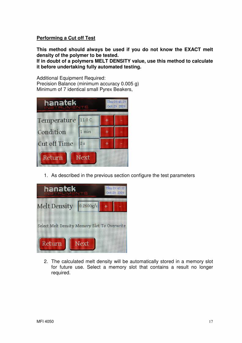
Performing a Cut off Test
This method should always be used if you do not know the EXACT melt density of the polymer to be tested. If in doubt of a polymers MELT DENSITY value, use this method to calculate it before undertaking fully automated testing. Additional Equipment Required: Precision Balance (minimum accuracy 0.005 g) Minimum of 7 identical small Pyrex Beakers,
1. As described in the previous section configure the test parameters
2. The calculated melt density will be automatically stored in a memory slot for future use. Select a memory slot that contains a result no longer required.

MFI 4050
18
3. Place the die in the barrel and fit the piston to the test weight. Pressing OK will lower the piston into the barrel so that all parts reach the test temperature.

MFI 4050
19
4. The instrument barrel will heat to the pre-set temperature. The user will not be able to progress to the next test stage until the correct temperature is reached. When the test temperature is reached the ready button will become active. Pressing the Ready button will raise the piston out of the barrel.
CAUTION PISTON WILL BE HOT
5. Fill the barrel with approximately 4 grams of polymer using the filling funnel supplied, Remove funnel after use.
CAUTION FUNNEL WILL BE HO

MFI 4050
20
6. Press OK to lower piston into barrel
7. Once the piston and test weight has reached the test zone the weight lift mechanism will rise to support the piston and weight at the start of the test zone for the remainder of the pre selected conditioning time.
8. The remaining conditioning time is displayed. At the end of the conditioning time the weight lift system is lowered and the piston and weight are left to force though the polymer under test.
9. When prompted cut off the pre-test zone waste polymer and discard.

MFI 4050
21
10. The first cut off period will begin, when the beep sounds, cut off the polymer and set aside, it is important that each cut off is labelled as it must later be entered in the correct order.
11. Continue to cut off and set aside as many samples as is possible into the Pyrex beakers. When the instrument reached the end of the test zone it will prompt the user to dispose of all remaining polymer.
12. When prompted cut off the left over waste polymer and discard.

MFI 4050
22
13. When the test is completed the Instrument will prompt the user to input the weight for each sample. Press enter to access the keys to manually input the weight to 3dp. If there was a problem cutting off a particular sample, leave the value as 0.00 and it will be excluded from the calculation. MD is calculated for each cut off by measuring the distance travelled for that cut off. It is therefore important that each cut off is input in the correct order.
14. After the test is complete the test results will be shown and the option to Print the results or clean the instrument.
Note The instrument should be cleaned after every use. (See cleaning cycle below) Printing the results with the optional printer will give a time and date stamped self adhesive label that can be attached to the job sheet or sample bag. Additional calculations are also reported.

MFI 4050
23
CLEANING THE INSTRUMENT
CLEANING THE INSTRUMENT IS BEST ACHIEVED WHILST COMPONENTS ARE HOT, HEATPROOF GLOVES SHOULD BE WORN AT ALL TIMES. The clean option can either be accessed after performing a test or through the options menu.
1. Once the test has been completed, the remaining polymer can be extruded from the orifice by manually pushing down on the weight. Once all remaining polymer has been extruded and discarded, pull out the die retaining slide so that the die drops out of the bottom of the barrel. TO AVOID DAMAGING THE DIE CATCH IT IN A SMALL PYREX BEAKER OR THE PALM OF A HEATPROOF GLOVE. If the Die does not fall out of the barrel place the beaker or glove under the barrel and continue to stage 2, when the cleaning probe enters the barrel it will push the die out. Whilst the die is still hot, use the die broach to remove any polymer from inside the orifice. Use the cut off knife to scrape any remaining plastic from the outside of the die. Place the clean die to one side. Use the cut off knife to remove any material from the die retainer slide.
2.
BE CAREFUL NOT TO TOUCH THE PISTON IT IS HOT

MFI 4050
24
Remove the test piston and scrape any remaining polymer from the shaft using the cut off knife. Use a cleaning patch to remove any further residue. Place the clean piston in the tool rack on the side of the instrument.
3. Fit the cleaning probe onto the MFI instrument test weight and lock the weight to the instrument using the Lock pin/ R clip.
4. Place a cleaning patch over the upper barrel opening. Press clean, the lift mechanism will force the cleaning patch through the barrel with the cleaning tool. Repeat this with a new patch three times or until the patch is uncontaminated after being passed through the barrel.

MFI 4050
25
TEMPRATURE VERIFICATION Precise temperature measurement is essential for accurate MFI testing. The Hanatek MFI instrument uses 3 independently controlled heater bands each with their own precision RTD temperature sensor to accurately monitor and control the temperature of the barrel. To verify the accuracy of the barrel temperature the operator can use the external temperature probe. This probe has 4 sensors, 3 are positioned in line with those fitted in the instrument barrel allowing accurate comparison to the instrument sensors to actual test area temperatures. The temperature verification is accessed from the options menu. In the options menu there is also the additional option to auto prompt the user to check the temperature of the barrel before every test.
The verification temperature can be set at any test temperature allowing the barrel to be verified at the precise temperature that testing is performed. The default is set to the last test temperature. Once the temperature has been selected and the probe is in the barrel press Verify.
Auto temperature Check option
Perform temperature Check

MFI 4050
26
The instrument will now heat the barrel to the pre-set temperature and compare the internal sensors to the sensors in the probe. If the verification fails indicating a higher then permitted difference between the two sets of sensors then the option to calibrate the instrument will be displayed. For further information on calibrating the MFI contact Hanatek instruments.

MFI 4050
27
AUTO SHUT DOWN and EMERGANCY STOP The Hanatek MFI instrument has been designed with maximum safety in mind. To access the auto shut down menu from the main screen press SYSTEM.
The instrument has built in an adjustable auto shut down option that will shut down the heaters in the instrument if left idle for a length of time. This can be set at 1h, 2h, 3h, 4h or Never. Selecting this option will avoid the instrument being left on unattended over night if the user forgets to turn it off.
The emergency stop button easily accessed on the top of the instrument once pressed will fully shut down the instrument. The heaters will turn off and the lift mechanism will stop in its current position. To release the Emergency stop button twist it clockwise. The instrument can then be re-powered up using the push button switch on the side of the instrument. Power Down When the MFI instrument is not in use it should be powered down. This will leave the instrument in a safe state with the test mass lowered. Remove the test piston or the cleaning probe if fitted to the test weight. In the system menu press the off button.

MFI 4050
28
Calibration The Hanatek MFI is supplied calibrated. We recommend re-certifying the instrument annually. This can be done by a Hanatek approved calibration engineer or the user can self certify the instrument using a Hanatek Calibration pack. The calibration pack will enable the user to calibrate the instrument using UKAS certified calibration artefacts.
The re-calibration kit consists of the following certified parts: Calibration Probe (replaces existing probe) Standard Testing Die (replaces existing Die) Standard Testing Piston (replaces existing Piston) Replacement inner Barrel (replaces existing Inner Barrel) Cleaning Patches Barrel Removal Tool

MFI 4050
29
Step 1 Replace all existing equipment with the newly supplied calibrated parts. Changing the inner barrel
The inner barrel can be removed using the removal tool. If the inner barrel is stuck in the instrument try heating the barrel. Once it is loose leave to cool before withdrawing it from the instrument.
IF REMOVING THE BARREL HOT WEAR HEAT PROOF GLOVES Fit the new inner barrel using the tool. Temperature Verification and Calibration The new calibration probe supplied with the calibration Pack has been certified by a UKAS calibration laboratory this piece of calibration equipment is used to calibrate the MFI with the new inner barrel fitted. Power up the instrument
Press calibrate Enter the serial number of the calibration pack. Enter the calibration code for the calibration pack

MFI 4050
30
Follow the on screen prompts to perform a full temperature calibration on the MFI instrument. Please be aware that the full calibration can take several hours and during this time the instrument will be heating up to its maximum working temperature. Ensure the Die and the probe is in the barrel.
MFI 4050
31
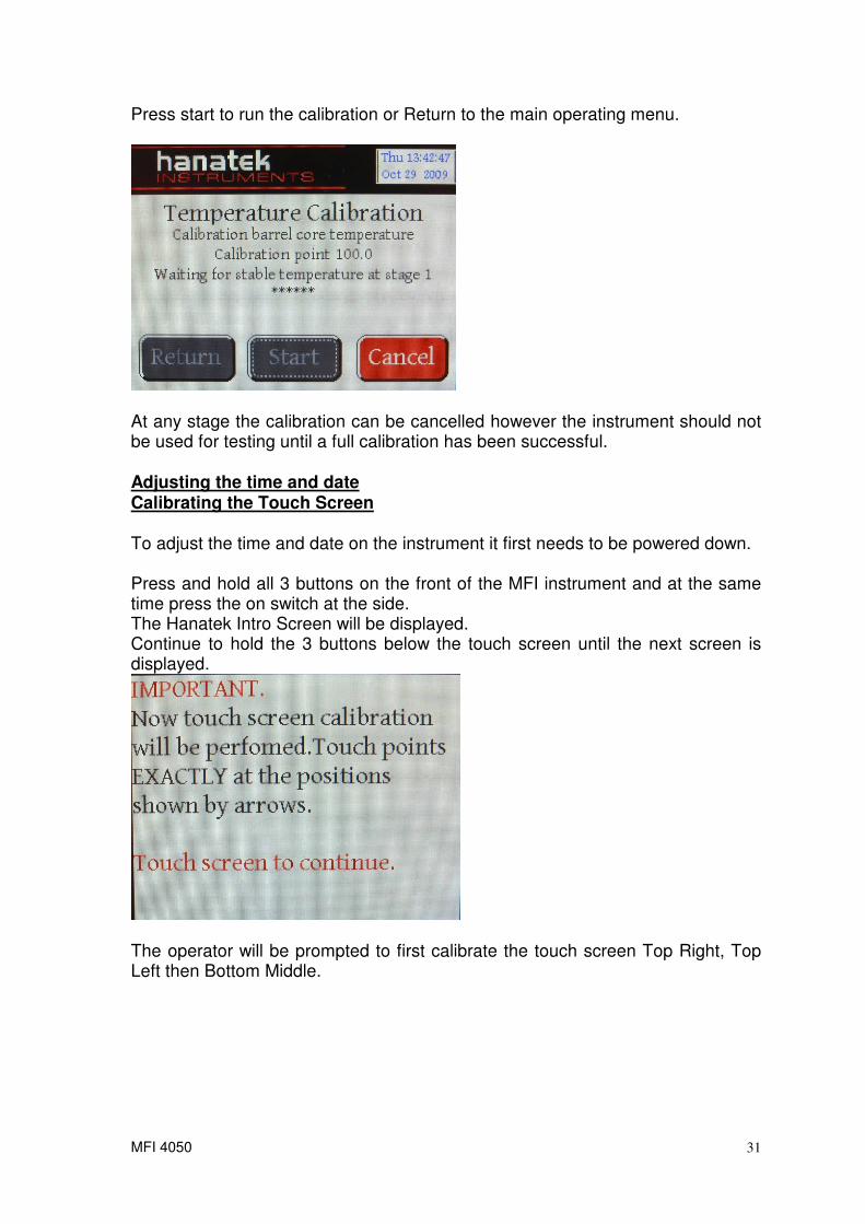
Press start to run the calibration or Return to the main operating menu.
At any stage the calibration can be cancelled however the instrument should not be used for testing until a full calibration has been successful. Adjusting the time and date Calibrating the Touch Screen To adjust the time and date on the instrument it first needs to be powered down. Press and hold all 3 buttons on the front of the MFI instrument and at the same time press the on switch at the side. The Hanatek Intro Screen will be displayed. Continue to hold the 3 buttons below the touch screen until the next screen is displayed.
The operator will be prompted to first calibrate the touch screen Top Right, Top Left then Bottom Middle.

MFI 4050
32
Touch to complete the touch calibration.
Set the new date and time and press EXIT.

MFI 4050
33
SPARES DESCRIPTION
PART NUMBER
Piston
Die - Standard 2.0955mm bore
Die Broach
Die Plug Gauge
Cleaning Tool
Cut-off Knife
Cleaning Patches (45/box)
Mirror
Spirit Level
67mm Heat Resistant Gloves
SERVICE
Contact- HANATEK Instruments: Telephone No: +44 (0)1424 739623 Fax Number: +44 (0)1424 730600 E-mail: [email protected] Web Site: www.hanatekinstruments.com

MFI 4050
34
Appendix A- THERMOPLASTIC MATERIALS AND THEIR ABBREVIATIONS POLYOLEFINES P/E Polyethylene LDPE Low Density P/E LLDPE Linear Low Density P/E MDPE Medium Density P/E HDPE High Density P/E HMWPE High Molecular Weight P/E UHMWPE Ultra High Molecular Weight P/E P/P Polypropylene EVA Ethylene Vinyl Acetate EPDM Elastomer Modified P/E - P/P CELLULOSICS C/A Cellulose/Acetate C/P Cellulose/Propionate CAB Cellulose/ Acetate/Butyrate ACRYLICS PMMA Polymethylmethacrylate. ACETALS POM Polyoxymethylene

MFI 4050
35

MFI 4050
36
EU Directive 2002/96/EC on WEEE (Waste Electrical & Electronic Equipment) and RoHS
(Restriction of the use of certain Hazardous Substances).
The European Union's Directive on Restriction of the use of certain Hazardous Substances in
electrical and electronic equipment (ROHS) defines each of 10 categories of electrical and
electronic equipment in Annex I . Category 9 is defined as follows:
9. Monitoring and control instruments
Smoke detector
Heating regulators
Thermostats
Measuring, weighing, or adjusting appliances for household or as laboratory equipment
Other monitoring and control instruments used in industrial installations (e.g. in control
panels).
The RoHS Directive defines the scope of restrictions in Article 2 as follows:
"1. Without prejudice to Article 6, this Directive shall apply to electrical and electronic
equipment falling under the categories I, 2, 3, 4, 5, 6, 7 and 10 set out in Annex IA to Directive
No 2002/96/EC (WEEE) and to electric light bulbs, and luminaires in households."
This product is supplied as a Monitoring and Control instrument and as such falls within
category 9 of the EU directive 2002/96/EC and so is excluded from restrictions under the scope
of the RoHS Directive.
The Waste Electrical and Electronic Equipment Directive is intended to reduce the amount of
harmful substances that are added to the environment by the inappropriate disposal of these
products through municipal waste.
Some of the materials contained in electrical and electronic products can damage the
environment and are potentially hazardous to human health; for this reason the products are
marked with the crossed out wheelie bin symbol which indicates that they must not he disposed
of via unsorted municipal waste.
Rhopoint Instruments Ltd have arranged a means for our customers to have products that have
reached the end of their useful life safely recycled. We encourage all end users to us at the end
of the product's life to return their purchase to as for recycling as per Article 9 of the WEEE
Directive.
Please contact us on +44 (0) 1424-739622 and we will advise on the process for returning these
waste products so we can all contribute to the safe recycling of these materials.