medium-voltage protection with auto-reclosure and · pdf filethis enables all the requirements...
TRANSCRIPT

Siemens PTD EA · Applications for SIPROTEC Protection Relays · 2005 1
Line Protection in Distribution Systems
� 1. IntroductionAn important protection criterion in medium-voltage applications is overcurrent-time protec-tion. Hardware redundancy can be dispensed within favor of lower-cost solutions, thanks to numer-ical technology and the high reliability of theSIPROTEC 4 protection relays. The SIPROTEC 4protection relays also allow functions which gobeyond the basic scope of protection:
� Unbalanced load (negative-sequence) pro-tection, motor protection functions, circuit-breaker failure protection,...
� Other voltage-dependent protection functionssuch as voltage protection, directionalovercurrent protection
� Auto-reclosure� Control, including interlocking� Integration in a control system
This enables all the requirements in the feeder tobe met with a single relay. Scalable, flexible hard-ware allows simple adaptation to any application.
� 2. Protection concept2.1 Overcurrent-time protectionThe task of overcurrent-time protection is to detectthe feeder currents, in order to initiate tripping bythe circuit-breaker in the event of overcurrent. Se-lectivity is achieved here by current grading or timegrading. The phase currents IL1, IL2 and IL3 and theearth current IE serve as measuring variables here.(Non-directional) overcurrent-time protection isused in medium-voltage power systems withsingle-end infeed or as backup protection inhigh-voltage applications.
Medium-Voltage Protectionwith Auto-Reclosure andControl
Fig. 1 SIPROTEC medium-voltage protection
Fig. 2 Block diagram
R_H
A25
-328
.tif

Line Protection in Distribution Systems
Siemens PTD EA · Applications for SIPROTEC Protection Relays · 20052
2.1.1 Grading and selectivityThe aim of every protective setting is to achieveselectivity, i.e. the protection relay closest to thefault location trips the CB; all the others detect thefault but do not switch off or at least only after adelay. This ensures backup protection if “regular”protection fails.
There are basically two criteria for achieving selec-tivity:
� TimeHere a protection relay initiates tripping imme-diately or with an adjustable delay time. Sincethe power system fault is usually detected by anumber of protection relays in the powersystem, the protection relay with the shortestdelay time initiates tripping. The delay times inthe individual protection relays are defined suchthat the short-circuit is cleared by the protec-tion relay closest to the fault.
This type of grading is normally used for cable andoverhead power line systems.
� CurrentAnother grading criterion may be the magni-tude of the short-circuit current itself. Since thesize of the short-circuit current cannot be deter-mined exactly in pure line or cable systems, thismethod is used for grading of transformers. Thetransformer limits the short-circuit current re-sulting in different magnitudes of short-circuitcurrent on the high and low-voltage side.This behavior is utilized to achieve selectivity intripping, as is attained in time grading.
The flexibility of SIPROTEC 4 overcurrent-timeprotection relays allows a mixture of these two cri-teria and therefore helps to achieve optimum sup-ply security.
2.1.2 Definite-time overcurrent protectionDefinite-time overcurrent protection is the maincharacteristic used in Europe (except in countrieswith a British influence). Delay times are assignedto several current pickup thresholds.
I>> pickup value (high short-circuit current)t>> (short delay time)
I> pickup value (low short-circuit current),t> (delay time)
2.1.3 Inverse-time overcurrent protectionThe inverse-time characteristic is widely used incountries with a British and American influence.Here the delay time is dependent on the currentdetected.
Inverse-time overcurrent protection characteristicsaccording to IEC 60255
IEC 60255-3 defines four characteristics whichdiffer in their slope.
InverseVery InverseExtremely InverseLong Inverse
The calculation formulae and the correspondingcharacteristics are shown below by way of com-parison.
Inverse
Very inverse
Extremely inverse
Long inverse
Fig. 22-stage definite-timeovercurrent characteristic(I>>, I>)
( )t T=
−⋅014
10 02
..
I Ip
p
( )t T=−
⋅135
1
.
I Ipp
( )t T=
−⋅80
1I Ip
2 p
( )t T=−
⋅120
1I Ipp
Fig. 3 Comparison of inverse-time overcurrentprotection characteristics

Siemens PTD EA · Applications for SIPROTEC Protection Relays · 2005 3
Line Protection in Distribution Systems
The corresponding characteristic is selected de-pendent on the overall grading coordinationchart. However, the inverse characteristic is suffi-cient for most applications.
Inverse-time overcurrent protection characteristicsaccording to ANSI/IEEE
Characteristics are also defined by ANSI/IEEEsimilar to those according to IEC 60255. Forfurther details about these, see the applicationexample on “Coordination of Inverse-TimeOvercurrent Relays with Fuses”. The ANSI char-acteristics are also available as standard in allSIPROTEC 4 overcurrent-time protection relays.
2.1.4 User-defined characteristicsNumerical protection relays like SIPROTEC 4 alsoallow the user to freely define characteristics, andtherefore enable maximum flexibility. This meansease of adaptation to existing protection concepts,e.g. when renewing the protection, even for specialapplications.
2.1.5 Combined characteristicsSIPROTEC 4 overcurrent-time protection allowsthe advantages of definite and inverse-timeovercurrent protection to be combined. On theone hand, with the high-set current stage I>>, thetripping time with high short-circuit currents canbe reduced in comparison with inverse-timeovercurrent protection characteristics, and on theother hand the grading can be adapted optimallyto the characteristic of the HV HRC fuses with in-verse-time overcurrent protection characteristic.
2.1.6 SensitivityThe earth current can be measured or calculatedin addition to the phase currents. Independentprotection stages for phase-to-earth faults are alsoavailable in the SIPROTEC 4. As a result, sensitiv-ity below the rated current is achieved for such afault.
2.2 Auto-reclosureAuto-reclosure is only used on overhead lines, be-cause the chances of success are relatively slight inthe event of faults in a cable network. About 85%of reclosures are successful on overhead lines,which contributes greatly to a reduction in powersystem downtimes.
Important parameters for reclosure are:
Dead timeLockout (blocking) timeSingle or three-poleSingle or multishot
Normally only one single three-pole reclosure isperformed for medium-voltage applications. Deadtimes between 0.3 and 0.6 s usually suffice for ade-quate de-ionization of the flashover distance andthus a successful reclosure.
The lockout times (time up to next reclosure) arechosen so that protection relays affected by thepower system fault have reliably reset. In the pastthis led to relatively long lockout times (approxi-mately 30 s) due to the dropout time of mechani-cal protection relays. This is not necessary in nu-merical protection relays. Shorter lockout timescan therefore reduce the number of final discon-nections (unsuccessful reclosures), for exampleduring thunderstorms.
In the past separate relays were used forprotection and automatic reclosure. The initiationfor this was given by parallel wiring with the pro-tection relay. In SIPROTEC 4 relays the auto-reclosure function can be integrated in the protec-tion relay; there is no need for any additional relayand wiring.
2.3 ControlThere is a noticeable worldwide trend towardsautomation, even in medium-voltage power sys-tems. SIPROTEC 4 protection relays provide theconditions for controlling the feeder both locallyand remotely by telecontrol/station control andprotection systems. This is supported by the ap-propriate control elements on the relay and vari-ous serial interfaces. See Chapter 4 for furtherinformation.
� 3. SettingsThe determining of the most important settingparameters is explained in this chapter by meansof a typical application.
3.1 Overcurrent-time protectionThe setting of the overcurrent stages is defined bythe grading coordination chart of the overall net-work. Current grading is possible for the “trans-former” protection object; only time grading canusually be applied for overhead lines/cables.
3.1.1 High-set current stage I>>The high-set current stage I>> is set under the ad-dress 1202 and the corresponding delay T I>> un-der 1203. It is normally used for current grading athigh impedances such as are encountered in trans-formers, motors or generators. Setting is such thatit picks up for short-circuits reaching into this im-pedance range.
Siemens PTD EA · Applications for SIPROTEC Protection Relays · 20054
Line Protection in Distribution Systems
Example:Transformer in the infeed of a busbar with the fol-lowing data:
Rated apparent power SNT = 4 MVAShort-circuit voltage Uk = 10 %Primary rated voltage UN1 = 33 kVSecondary rated voltage UN2 = 11 kVVector group Dy 5Neutral earthedShort-circuit poweron 33 kV side 250 MVA
The following short-circuit currents can be calcu-lated from these data:
3-pole, high-voltage side short-circuitI"SC3 = 4389 A
3-pole, low-voltage side short-circuitI"SC3, 11 = 2100 A
on the high-voltage side flowI"SC3,33 = 700 A
rated current of the transformer HVINT, 33 = 70 A (high-voltage side)
rated current of the transformer LVINT, 11 = 211 A (low-voltage side)
current transformer (high-voltage side)INW, 33 = 100 A / 1 A
current transformer (low-voltage side)INW, 11 = 300 A / 1 A
Due to the setting value of the high-set currentstage I>>
I>>/IN >1
U
I
k Transfo
N Transfo
N CT
⋅I
the following setting on the protection relay:
The high-set current stage I> must be set higherthan the maximum short-circuit current detectedon the high-voltage side in the event of a fault onthe low-voltage side. In order to attain a sufficientnoise ratio even at fluctuating short-circuit power,a setting of
I>>/IN = 10, i.e. I>> = 1000 A
is selected.
Increased inrush current surges are disarmed bythe delay times (parameter 1203 T I>>) providedtheir fundamental component exceeds the settingvalue. The set time is a purely additional time de-lay which does not include the operating time.
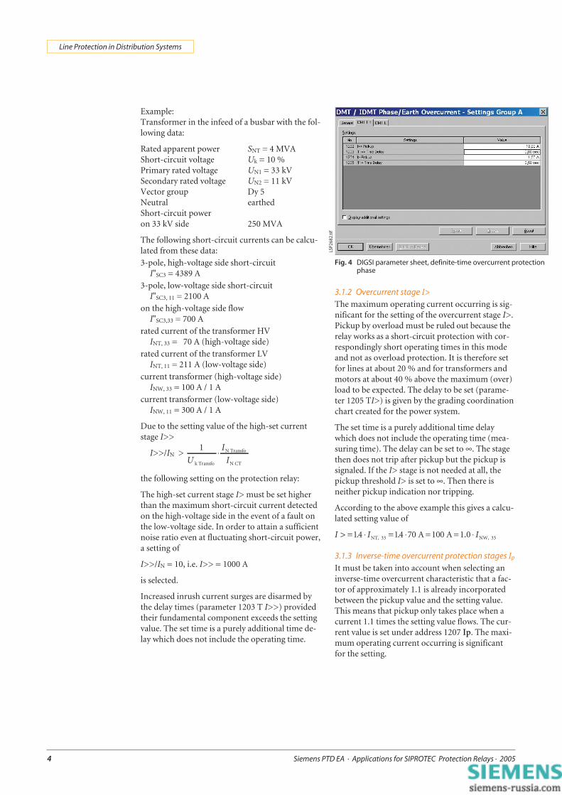
3.1.2 Overcurrent stage I>The maximum operating current occurring is sig-nificant for the setting of the overcurrent stage I>.Pickup by overload must be ruled out because therelay works as a short-circuit protection with cor-respondingly short operating times in this modeand not as overload protection. It is therefore setfor lines at about 20 % and for transformers andmotors at about 40 % above the maximum (over)load to be expected. The delay to be set (parame-ter 1205 TI>) is given by the grading coordinationchart created for the power system.
The set time is a purely additional time delaywhich does not include the operating time (mea-suring time). The delay can be set to ∞. The stagethen does not trip after pickup but the pickup issignaled. If the I> stage is not needed at all, thepickup threshold I> is set to ∞. Then there isneither pickup indication nor tripping.
According to the above example this gives a calcu-lated setting value of
I I> = ⋅ = ⋅ ⋅14 14 70. .NT, 33 NW, 33A =100 A =1.0 I
3.1.3 Inverse-time overcurrent protection stages Ip
It must be taken into account when selecting aninverse-time overcurrent characteristic that a fac-tor of approximately 1.1 is already incorporatedbetween the pickup value and the setting value.This means that pickup only takes place when acurrent 1.1 times the setting value flows. The cur-rent value is set under address 1207 Ip. The maxi-mum operating current occurring is significantfor the setting.
Fig. 4 DIGSI parameter sheet, definite-time overcurrent protectionphase
LSP2
682.
tif
Siemens PTD EA · Applications for SIPROTEC Protection Relays · 2005 5
Line Protection in Distribution Systems
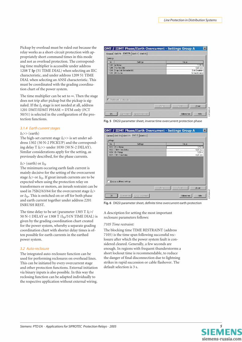
Pickup by overload must be ruled out because therelay works as a short-circuit protection with ap-propriately short command times in this modeand not as overload protection. The correspond-ing time multiplier is accessible under address1208 T Ip (51 TIME DIAL) when selecting an IECcharacteristic, and under address 1209 51 TIMEDIAL when selecting an ANSI characteristic. Thismust be coordinated with the grading coordina-tion chart of the power system.
The time multiplier can be set to ∞. Then the stagedoes not trip after pickup but the pickup is sig-naled. If the Ip stage is not needed at all, address1201 DMT/IDMT PHASE = DTM only (FCT50/51) is selected in the configuration of the pro-tection functions.
3.1.4 Earth current stagesIE>> (earth)The high-set current stage IE>> is set under ad-dress 1302 (50 N-2 PICKUP) and the correspond-ing delay T IE>> under 1030 (50 N-2 DELAY).Similar considerations apply for the setting, aspreviously described, for the phase currents.
IE> (earth) or IEp
The minimum occuring earth fault current ismainly decisive for the setting of the overcurrentstage IE> or IEp. If great inrush currents are to beexpected when using the protection relay ontransformers or motors, an inrush restraint can beused in 7SJ62/63/64 for the overcurrent stage IE>or IEp. This is switched on or off for both phaseand earth current together under address 2201INRUSH REST.
The time delay to be set (parameter 1305 T IE>/50 N-1 DELAY or 1308 T /IEp/51N TIME DIAL) isgiven by the grading coordination chart createdfor the power system, whereby a separate gradingcoordination chart with shorter delay times is of-ten possible for earth currents in the earthedpower system.
3.2 Auto-reclosureThe integrated auto-reclosure function can beused for performing reclosures on overhead lines.This can be initiated by every overcurrent stageand other protection functions. External initiationvia binary inputs is also possible. In this way thereclosing function can be adapted individually tothe respective application without external wiring.
A description for setting the most importantreclosure parameters follows:
7105 Time restraint:
The blocking time TIME RESTRAINT (address7105) is the time span following successful rec-losure after which the power system fault is con-sidered cleared. Generally, a few seconds areenough. In regions with frequent thunderstorms ashort lockout time is recommendable, to reducethe danger of final disconnection due to lightningstrikes in rapid succession or cable flashover. Thedefault selection is 3 s.
Fig. 5 DIGSI parameter sheet, inverse time overcurrent protection phase
DIGSI parameter sheet, definite time overcurrent earth protection
LSP2
683.
tif
LSP2
684.
tif

Siemens PTD EA · Applications for SIPROTEC Protection Relays · 20056
Line Protection in Distribution Systems
7117 Action time
The action time checks the time between thepickup of a relay and the trip command of a pro-tection function parameterized as a starter, inready (but not yet running) auto-reclosure.If a trip command is received from a protectionfunction parameterized as a starter within the ac-tion time, auto-reclosure is initiated. If this time isoutside the parameterized value of T-ACTION(address 7117), auto-reclosure is blocked dynami-cally. With inverse-time characteristics the releasetime is determined essentially by the fault locationand the fault resistance. With the help of the ac-tion time, no reclosure is performed in the eventof very remote or high-resistance faults with along tripping time.Presetting of ∞ always initiates a reclosure.
7135 Number of reclosure attempts, earth7136 Number of reclosure attempts, phaseThe number of reclosures can be set separately forthe programs “Phase” (address 7136, NUMBER RCPHASE/# OF RCL. PH) and “Earth” (address 7135NUMBER RC EARTH/# OF RCL. GND). The pre-setting for both parameters is 1 (one); one reclosurecycle is therefore executed.
The “configuration sheet” defines which of theprotection stages starts the reclosure. For each ofthe stages it can be decided whether this stagestarts the reclosure, does not start it or blocks itout.
7127 Dead time 1: ph7128 Dead time 1: G
The parameters 7127 and 7128 define the lengthof the dead times of the 1st cycle. The time definedby the parameter is started upon opening thecircuit-breaker (if auxiliary contacts are allocated)or upon reset after the trip command.
The dead time before the 1st reclosure for thereclosure program “Phase” (phase-to-phase fault)is set in address 7127 DEADTIME 1:PH; for thereclosure program “Earth” (single phase-to-earthfault) it is set in address 7128 DEADTIME 1:G.The duration of the dead time should relate to thetype of application. For longer lines the timeshould be long enough for the short-circuit arc toextinguish and de-ionize the ambient air, to allowsuccessful reclosure (usually 0.9 s to 1.5 s). Thestability of the power system has priority in thecase of lines fed from several ends. Since the dis-connected line cannot develop any synchronizingforces, often only a short dead time is permissible.Normal values are between 0.3 s and 0.6 s. Longerdead periods are usually allowed in radial systems.The default is 0.5 s.
DIGSI parameter sheet, auto-reclosure (general)
Fig. 8 DIGSI parameter sheet, auto-reclosure configuration
Fig. 9 DIGSI parameter sheet, auto-reclosure (1st reclosure cycle)
LSP2
561e
n.ti
f
LSP2
686.
tif
LSP2
687.
tif
Siemens PTD EA · Applications for SIPROTEC Protection Relays · 2005 7
Line Protection in Distribution Systems
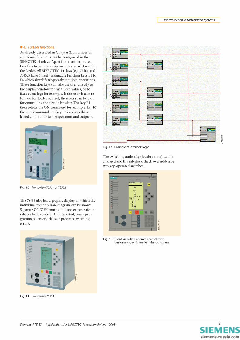
� 4. Further functionsAs already described in Chapter 2, a number ofadditional functions can be configured in theSIPROTEC 4 relays. Apart from further protec-tion functions, these also include control tasks forthe feeder. All SIPROTEC 4 relays (e.g. 7SJ61 and7SJ62) have 4 freely assignable function keys F1 toF4 which simplify frequently required operations.These function keys can take the user directly tothe display window for measured values, or tofault event logs for example. If the relay is also tobe used for feeder control, these keys can be usedfor controlling the circuit-breaker. The key F1then selects the ON command for example, key F2the OFF command and key F3 executes the se-lected command (two-stage command output).
The 7SJ63 also has a graphic display on which theindividual feeder mimic diagram can be shown.Separate ON/OFF control buttons ensure safe andreliable local control. An integrated, freely pro-grammable interlock logic prevents switchingerrors.
The switching authority (local/remote) can bechanged and the interlock check overridden bytwo key-operated switches.
Fig. 10 Front view 7SJ61 or 7SJ62
Fig. 11 Front view 7SJ63
Fig. 12 Example of interlock logic
Fig. 13 Front view, key-operated switch withcustomer-specific feeder mimic diagram
LSP2
299.
eps
LSP2
316.
eps
LSP2
565.
tif
LSP2
564.
tif

Siemens PTD EA · Applications for SIPROTEC Protection Relays · 20058
Line Protection in Distribution Systems
� 5. Connection examples5.1 Current and voltage transformersConnection of the protection relays to theswitchgear depends on the number of switchingobjects (circuit-breakers, disconnectors) and cur-rent and voltage transformers. Normally at leastthree current transformers are available per feederwhich are connected to the protection relay as fol-lows.
In some systems, also the earth current is mea-sured by a core-balance current transformer. Thiscan be connected to the protection relay sepa-rately. A core-balance current transformer achie-ves greater accuracy (sensitivity) for low earthcurrents.
If voltages are also available (from the feeder oras a busbar measurement), these can be connectedon 7SJ62/63/64 and then also enable voltage-dependent protection functions (directional over-current protection, voltage protection, frequencyprotection, ...).
5.2 Input/output peripheryIn addition to the current transformers (and ifrequired to the voltage transformers too), at leastthe TRIP command has to be wired to the circuit-breaker. The standard allocation supports this bypractice-oriented preassignment.
Preassignment of the inputs and outputs in the7SJ610:
Binary inputs
BI1 Block definite/inverse timeovercurrent protection
BI2 LED resetBI3 Display lighting on
Binary outputs (command relays)
BO1 TRIP commandBO2 Reclosure commandBO3 Reclosure commandBO4 MV monitoring
Fig. 14 Transformer connection to three current trans-formers
Fig. 15 Transformer connection to three current trans-formers and core-balance CT
Important: The cable shield must be earthed on the cable side!
Note: Reversing the current polarity (address 0201) also reversesthe polarity of the current input IE
Fig. 16 Transformer connection to three current and three voltagetransformers
Siemens PTD EA · Applications for SIPROTEC Protection Relays · 2005 9
Line Protection in Distribution Systems
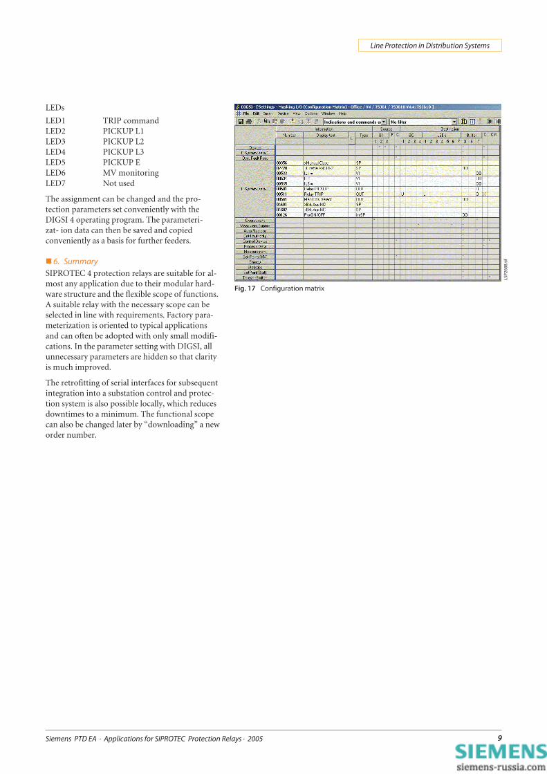
LEDs
LED1 TRIP commandLED2 PICKUP L1LED3 PICKUP L2LED4 PICKUP L3LED5 PICKUP ELED6 MV monitoringLED7 Not used
The assignment can be changed and the pro-tection parameters set conveniently with theDIGSI 4 operating program. The parameteri-zat- ion data can then be saved and copiedconveniently as a basis for further feeders.
� 6. SummarySIPROTEC 4 protection relays are suitable for al-most any application due to their modular hard-ware structure and the flexible scope of functions.A suitable relay with the necessary scope can beselected in line with requirements. Factory para-meterization is oriented to typical applicationsand can often be adopted with only small modifi-cations. In the parameter setting with DIGSI, allunnecessary parameters are hidden so that clarityis much improved.
The retrofitting of serial interfaces for subsequentintegration into a substation control and protec-tion system is also possible locally, which reducesdowntimes to a minimum. The functional scopecan also be changed later by “downloading” a neworder number.
Fig. 17 Configuration matrix
LSP2
688.
tif

Siemens PTD EA · Applications for SIPROTEC Protection Relays · 200510
Line Protection in Distribution Systems