medium access control of wireless lans - … · medium access control of wireless lans for mobile...
TRANSCRIPT
First published in IEEE Network MagazineSeptember/October 1994, Volume 8, Number 5
Medium Access Control of Wireless LANs forMobile Computing
To provide high-speed seamless services for mobile computing, an effective mediumaccess control capable of dealing with mobility issues in multicell wireless local area
networks is needed.
Kwang-Cheng Chen
With the spread of high performance portable computers and the need to network computers, dataterminals, and devices such as personal digital assistants (PDAs), wireless local area networks havebecome an emerging technology for today’s computer and communication industries. Accordingly, theIEEE project 802 formed study group 802.11 to establish a recommended international standard forwireless LANs that will support high bandwidth wireless data networking. The scope of this effort is todefine physical layer wireless data networking and physical layer transmissions (PHY) by radio orinfrared and medium access control protocols (MAC) compatible with the existing standards for higherlayers.
The physical layers discussed include direct sequence spread spectrum (DS-SS), frequency hoppedspread spectrum (FH-SS), and diffuse infrared. Both spread spectrum transmissions are in the 2.4 to2.4835GHz ISM1 band, according to FCC part 15.247. Other PCS frequency bands shall be consideredin the future.
Types of Wireless LANs
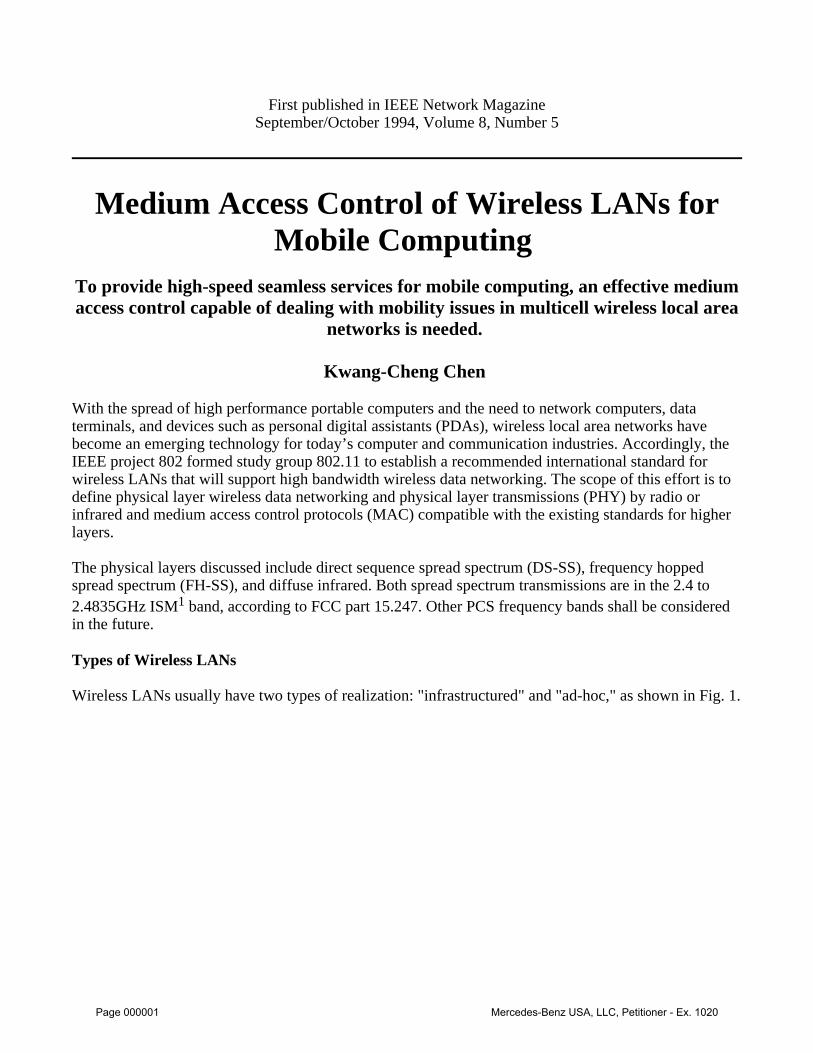
Wireless LANs usually have two types of realization: "infrastructured" and "ad-hoc," as shown in Fig. 1.
Page 000001 Mercedes-Benz USA, LLC, Petitioner - Ex. 1020
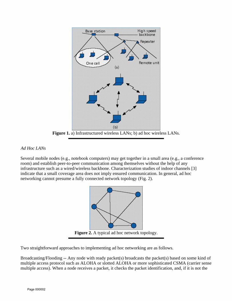
Figure 1. a) Infrastructured wireless LANs; b) ad hoc wireless LANs.
Ad Hoc LANs
Several mobile nodes (e.g., notebook computers) may get together in a small area (e.g., a conferenceroom) and establish peer-to-peer communication among themselves without the help of anyinfrastructure such as a wired/wireless backbone. Characterization studies of indoor channels [3]indicate that a small coverage area does not imply ensured communication. In general, ad hocnetworking cannot presume a fully connected network topology (Fig. 2).
Figure 2. A typical ad hoc network topology.
Two straightforward approaches to implementing ad hoc networking are as follows.
Broadcasting/Flooding -- Any node with ready packet(s) broadcasts the packet(s) based on some kind ofmultiple access protocol such as ALOHA or slotted ALOHA or more sophisticated CSMA (carrier sensemultiple access). When a node receives a packet, it checks the packet identification, and, if it is not the
Page 000002

destination, rebroadcasts the packet. Channel utilization is low, although implementation is easy. Also,broadcasting does not guarantee connection of all mobile nodes and users may need to find a "goodlocation" to have clear reception.
The nodes may set up a temporary infrastructure -- that is usually a hierarchical packet passing scheme.A typical example is the spokesman election algorithm (SEA) that elects a node as the base station.Unfortunately, this approach usually requires solving an NP-hard problem and thus is useful only in anetwork with a small number of nodes. Furthermore, due to fading, the procedure must be updatedperiodically. This overhead reduces channel efficiency.
Despite the possibility of ad hoc networking, most applications require communication with serviceslocated in a pre-existing infrastructure. Such an infrastructure is typically a higher-speed wired (orwireless) backbone. Therefore, we can divide typical network traffic into two directions: uplink (into thebackbone) and downlink (from the backbone). The contact points to the backbone with wireless medium(i.e., common air) are called access points. The access points can be either base stations or repeaters forenlarging the coverage area of communication.
Downlink Traffic
Due to the limited bandwidth of wireless LANs, a common channel is typically used for communicationbetween an access point and mobile nodes (or even a common channel for all access points and mobilenodes). Downlink communication is achieved by broadcasting on this common channel. More precisely,the access point(s) broadcasts packets to all mobile node(s) even if there is only one destination.Broadcasting introduces two important considerations in the implementation of a wireless LAN.
Multicasting -- Although it may be a necessary function, multicasting is not prohibited by the means ofphysical transmission. However, there might be a problem as illustrated below. Suppose there are 200nodes within the coverage of a base station, each packet is 1Kb long, and the bit error rate is 10-5 foreach transmitter-receiver pair. The resulting packet error rate is 10-2, and the probability that at least onenode misreceives the multicast packet is approximately 0.866. If the packet is re-multicast to correct theerror, some other node that earlier correctly received the packet might now experience an error. Onaverage, it takes 7.46 transmissions (1/(1-0.866)) for all nodes to correctly receive the multicast. Thisproblem can be overcome by the following two methods:
* Multiple broadcasting for each multicast: the base station broadcasts the multicast packetmultiple times with a higher sequence number each time. A mobile node needs to receivecorrectly only once. The resulting packet error rate for 200 nodes with an individual packeterror rate of 10-2 is 0.02 and the average packet transmission time is 1.02, significantly lessthan 7.46 in the previous scheme. * No acknowledgement for multicast: another way to solve the above problem is simply notto use acknowledgement. Under the assumption that the mobile nodes must be able to "hear"the base station and the packet error rate is usually small, this approach works reasonablywell. However, reliable packet delivery is not guaranteed.
Normal and Sleep Modes -- In order to save the battery power, mobile nodes must operate in twomodes: normal and sleep. Typically, a packet will be destined to only one or a few of the nodes on aLAN. There must be either a signaling procedure to wake up the destination, or some means wherebynodes can check the packet’s destination address and discard those packets not matching their address.
Page 000003

The latter is problematic. State-of-the-art wideband transmission may consume up to 100mW (or even1W, according to the regulations of FCC part 15.247). But the receiver’s digital signal processing andRF circuits may consume 100 mA of electrical current or even more. Since the receiving time is alwaysmuch longer than the transmitting time, receiving power consumption is usually the dominant factor inpower management.
The final important issue about the downlink is that nodes on modern LANs often operate in aclient-server mode. For instance, there might be a high performance workstation or PC acting as a fileserver. A request for file transfer on the uplink may result in a huge file transfer on the downlink. As aconsequence, downlink activity may constitute up to 75 to 80 percent of the total traffic in wirelessLANs.
Uplink Traffic
Uplink traffic generally needs a multiple access protocol to organize the transmissions from mobilenodes. This topic has been studied extensively [1-2, 4-11, 16-18]. There are several reasons whymultiple access is more difficult for wireless LANs than for wired LANs.
Dynamic Physical Channel Characteristics
Wireless LANs typically operate in very strong multipath fading channels that can change theircharacteristics in a very short time or in a very short distance, and which may not be reciprocal. Suchfading channels may make communication unreliable and may result in capture that leads to unfairaccess. According to channel measurements and modeling in the primary operating environment of highperformance wireless networks -- indoor radio propagation -- the channel statistics (thus received signalstrength) may change significantly within 10 to 20 ms duration or any movement of 1 foot distance [3].Therefore, the network topology may change within 10 to 20 ms for fixed nodes and 1 foot movementfor mobile nodes. Past research on multiple access protocols was usually based on the assumption ofrather reliable physical transmission, which is not a reasonable assumption for wireless LANs.
Practical Implementation
The wireless medium is quite different from cable or optical fiber. Thus, many functions that are trivialto implement in a wired medium cannot easily be applied to a wireless medium. For example, carriersensing in cable is easy but carrier sensing in radio takes at least 30 to 50 µs -- by itself a nontrivialportion of a packet transmission time.
Mobility and Dynamic Network Topology
A primary application of wireless LANs is to serve mobile users. Both channel characteristics and nodemobility can change the connections among nodes and thus the network topology. Furthermore, suchchanges can be very dynamic, occurring within tens of milliseconds. Network protocols must be able todeal with mobility issues in order to provide seamless services. In other words, the network mustmaintain normal operation while its topology changes with time.
Furthermore, a short range of transmission is desirable so that mobile nodes can save valuable batterypower and so that the whole network can adopt the concept of frequency reuse (explained below) forspectrum efficiency. Accordingly, infrastructure LANs are based on some access points that divide the
Page 000004

service area of a wireless LANs into different corresponding "cells" (or known as basic service areas).
Spatial Behavior and Handoff
User mobility also implies that cells must be properly overlapped. The "proper" overlap among cellsshould be large enough to guarantee no service holes and small enough not to reduce the spectrumefficiency very much (at least for traditional ALOHA family protocols [12]). A further implication is theneed for appropriate coordination among access points to provide seamless service to mobile nodes.
Wireless LANs may introduce spatial domain behavior due to multicell structure. One of the primaryreasons to adopt cellular structure is to increase the effective total bandwidth by using differentfrequencies in different cells. This concept, known as frequency reuse, is illustrated in the followingexample. Figure 3 is a seven-cell structure; suppose a total of 3-B bandwidth is needed to serve users inthe seven-cell area. Three different frequency bands can cover this seven-cell region. If frequency reusewere not employed and a single frequency band served all users in the same region, a total of 7-Bbandwidth would be needed to support the same level of quality of service. As a result of frequencyreuse, the total available communication bandwidth for all users is much larger than the transmissionspeed. Furthermore, frequency reuse not only saves the spectrum but also reduces transmission power byreducing cell size.
Figure 3. Frequency reuse layout example.
A function that allows a mobile node to communicate with the access point in a cell and then switch tothe access point in another cell is called handoff or handover. The purpose of handoff is to keepcontinuous or seamless service to mobile nodes through different cell coverages. Handoff isconsequently a special feature to deal with the mobility issue for wireless networks.
Handoff can be controlled by a central switching office (centralized handoff) or by mobile nodes(decentralized handoff). In cellular networks [13-14], handoff is done by the centralized approach. Theswitching office collects the signal strength information from the uplink. Monitoring the signal strengthof all mobile nodes, the switching office decides handoff based on any of a wide variety of algorithms.We summarize some typical algorithms as follows.
Simple Handoff -- Suppose the mobile node is under the coverage of base station N. When the signalstrength in the communication link between the mobile node and the base station M is larger than thatbetween the mobile node and base station N, the network will decide to hand the mobile node from N toM.
Page 000005
"Smooth" Handoff -- The difference between simple handoff and soft handoff lies on two-leveladjustment. Following the same example, let the signal strength between M and the mobile node be Mand that between N and the node be N. Define = M - N . Simple handoff algorithm decides to
change from N to M if > 0. For soft handoff, we determine two constants - < + in advance. If * > *- ,
then the network switching office is ready to make a handoff for the mobile node. If > + , the handoff
is executed. We can further improve this algorithm to adaptive versions.
Handoff can also be executed in distributed fashion such as in Bellcore’s WACS system or even using aspecial signaling channel [19]. Handoff is a function that can effect the design of protocols at severallayers. A typical approach is to associate with power control and coordination of access points vianetwork management.
Uplink Multiple Access Is the Core
To recognize and register new mobile nodes that join the network in any time and place, a kind ofrandom access protocol is surely needed. But once the uplink connection has been set up, random accessmay not be required. If the channel is static, we may consider this situation as a wired network.Unfortunately, the assumption of static channels is clearly not reasonable. Many researchers in the areaof wireless communication therefore have proposed reservation techniques to maintain services,especially for time bounded services such as voice and video. Consequently, the uplink protocol is thecore task for the MAC design of wireless LANs and the medium access design of any wireless datanetwork to support mobile computing.
Expected Features of Wireless LAN MAC
The 802.11 study group stated 20 requirements for a decent MAC protocol. These requirements,described below, may generally be considered as the expected features of any wireless LAN, not just anIEEE 802.11 LAN.
Throughput -- Since spectrum is a scare resource, throughput is definitely one of the most criticalconsiderations in the design of a MAC protocol. Random access protocols can be generally divided intotwo categories: the tree family and the ALOHA family (including CSMA). The ALOHA family suffersfrom stability problems. That is, the peak throughput is accompanied by tremendous delay. TakeEthernet for example. With 10-Mb/s physical transmission and over 80 percent throughput forCSMA/CD, Ethernet can deliver over 8 Mb/s performance in principle. In fact, practical measurementsshow that only 3 to 3.5-Mb/s performance is achieved. Consequently, operating throughput is practicallymore important than theoretical throughput.
Delay -- Delay characteristics are important for every application, but especially for time-boundedservices and multimedia applications such as voice and video.
Transparent to Different PHY Layers -- One of the special requirements for a wireless LAN MAC istransparency to different physical transmission layers. For IEEE 802.11 LANs, physical transmissionlayers include direct sequence spread spectrum, frequency-hopped spread spectrum, and diffuse infrared.These physical transmission layers are different not only in system design but also in propagationcharacteristics; however, one MAC must handle all of them. One way to achieve this goal is to have aphysical dependent layer, a physical convergence layer, and an appropriate MAC-PHY interface in each
Page 000006

station. This architecture is shown in Fig. 4. Based on such an architecture currently adopted by theIEEE 802.11 committee, a single MAC can exchange data with different PHYs transparently via theMAC-PHY interface.
Figure 4. Architecture of wireless LANs.
Ability to Serve Data, Voice, and Video -- With the increasing popularity of multimedia applications,desirable wireless LAN must be able to provide some time-bounded services such as voice and video inaddition to the mandatory data service.
Fairness of Access -- The fading characteristics of indoor channels may cause unequal received power atthe base station even when power control is enforced. Such a situation may result in unfair access to thenetwork. That is, one mobile node may have much less power received at the base station than anothermobile node. When the MAC protocol is operating in the contention mode (necessary for initialregistration and often used for uplink traffic), the disadvantaged mobile node may not have the chance toaccess the channel for a while. A MAC protocol should be able to resolve this situation since it ispossible that capture can happen with as small as 6 to 9 dB power difference while the dynamic range offading can be as large as several tens of dB.
Battery Power Consumption -- Since the primary purpose of wireless LANs is to serve mobile nodes,and since mobile nodes typically rely on battery power, efficient utilization of transmit and receivepower is another important consideration for a MAC protocol. Many proposed higher level protocolsrequire mobile nodes to constantly monitor access points or handshake with base stations for the purposeof synchronization, power control, or exchanging state information. Therefore, very limited powershould be used for packet transmission. Sleep mode should be possible at the receiver front end. Activereceive mode may consume more battery power than transmission mode operation since moderncommercial digital communication systems may typically have transmission power like 100 mW butneed 100 mA of current to support the digital signal processor operation at the receiver.
Maximum Number of Nodes -- According to market studies, a wireless LAN may need to supporthundreds of nodes. Therefore, a MAC should not limit the maximum number of nodes in order tomaintain satisfactory performance.
Robustness in Collocated Networks -- A big challenge to design a wireless LAN MAC is to worksuccessfully in the case of collocated networks. It is quite likely for two or more wireless LANs to
Page 000007

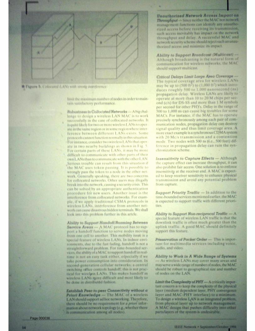
operate in the same region or in some region where interference between different LANs exists. Someprotocols cannot function normally in this situation. For instance, consider two wireless LANs thatoperate in two nearby buildings as shown in Fig. 5. For certain parts of these LANs, it may be moredifficult to communicate with other parts of their own LANs than to communicate with the other LAN.Serious trouble can result from this situation if the MAC uses token passing. It is possible to wronglypass the token to a node in the other network. Generally speaking, there are two concerns for collocatednetworks. Other users may illegally break into the network, causing a security crisis. This can be solvedby an appropriate authentication procedure for new users. Another issue is the interference fromcollocated networks. For example, if we apply traditional CSMA protocols in wireless LANs,interference from another network can cause disastrous hidden terminals. We shall look into thisproblem further in this artcle.
Fig. 5. Colocated LANs with strong interference.
Ability to Support Handoff/Roaming Between Service Areas -- A MAC protocol has to support ahandoff function to serve nodes moving from one cell to another. This mobility issue is a special featureof wireless LANs. In indoor environments, due to the fast fading, handoff is not a straightforwardproblem. For time-bounded services, the ability of a MAC to support handoff in real-time is not an easytask either, especially if we take power consumption into consideration. In second-generation cellularnetworks, a central switching office controls handoff; this is not practical for wireless LANs. This makeshandoff in wireless LANs more difficult and most likely to be done in distributed fashion.
Establish Peer-to-peer Connectivity without a Priori Knowledge -- The MAC of a wireless LAN shouldsupport ad hoc networking. Therefore, there should be no requirement for a priori information aboutnetwork topology (e.g., whether there is communication among all nodes).
Unauthorized Network Access Impact on Throughput -- Since neither the MAC nor networkmanagement functions can identify any unauthorized access before receiving its transmission, suchaccess inevitably has impact on the network throughput and delay. A successful MAC and networksecurity scheme should reject such an unauthorized access and minimize its impact.
Ability to Support Broadcast (Multicast) -- Although broadcasting is the natural form of communicationfor wireless networks, the MAC should support multicast.
Critical Delays Limit Large Area Coverage -- The typical coverage area for wireless LANs may be up to(500 ft2) to (1,000 ft2) which introduces roughly 500 to 1,000 nanosecond (ns) propagation delay.Wireless LANs are likely to operate at more than 10 to 20 M chips per second (c/s) for DS-SS and more
Page 000008
than 1 M symbols per second for other PHYs. Delay in the range of 500 to 1,000 ns can cause bigtroubles for some MACs. For instance, if the MAC has to operate precisely synchronously among eachpair of communication nodes, propagation delay can destroy signal quality and thus limit coverage area.A more exact example is a synchronous CDMA system with 20 Mc/s transmission and a contentionmode. Two nodes with 500 ns (i.e., 500 feet) difference in propagation delay can ruin thesynchronization scheme.
Insensitivity to Capture Effects -- Although the capture effect can increase throughput, it can alsoprohibit fair access. One solution is to enforce insensitivity at the receiver end. A MAC is expected tokeep receiver sensitivity to enhance physical transmission and avoid any potential problem from capture.
Support Priority Traffic -- In addition to the time-bounded services mentioned earlier, the MAC isexpected to support traffic with different priorities.
Ability to Support Non-reciprocal Traffic -- A special feature of wireless LAN traffic is that thedownlink traffic is often much greater than the uplink traffic. A good MAC should definitely supportthis feature.
Preservation of Packet Order -- This is important for multimedia services including voice, audio, andvideo.
Ability to Work in A Wide Range of Systems -- As wireless LANs may cover many areas and mayserve a wide range of number of nodes, the MAC should be robust to geographical size and number ofnodes on the LAN.
Limit the Complexity of PHY -- A critically important concern is to keep the complexity of the physicallayer (medium dependent layer, PHY convergence layer and MAC-PHY interface) to a minimum. Todesign a wireless LAN is an integrated problem, from physical layer up to network management. AMAC design that pushes difficulty into other parts/layers of the system is undesirable.
Ability to Market and Complexity -- The final step for success of wireless LANs is to deliverhigh-quality products in time to users, which usually means that simplicity is beauty.
More on Interference
In addition to above considerations, there are more concerns with infrastructure LANs. Multicellcoverage is governed by an access point which is typically a base station or a repeater. The coverage ofeach cell should overlap neighboring cell(s) properly, that is, the overlapping region is intended to beminimized to increase system capacity but also kept to certain portion so that seamless service ispossible. This joint region among cells introduces extra problems.
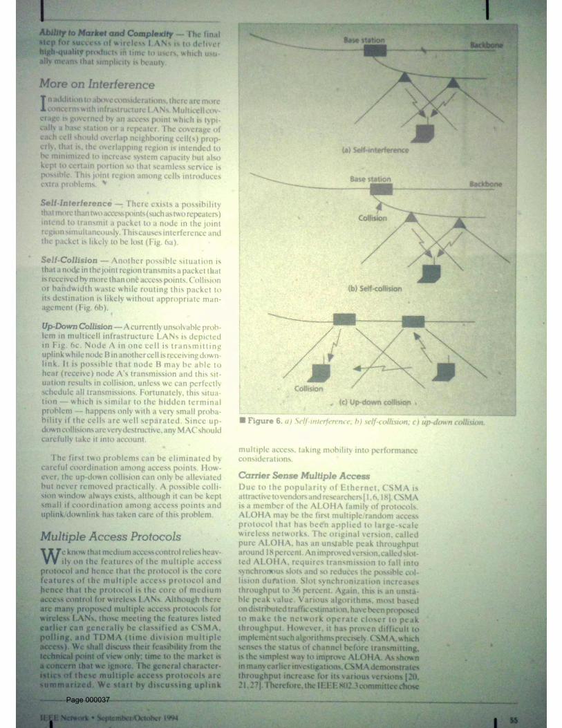
Self-Interference -- There exists a possibility that more than two access points (such as two repeaters)intend to transmit a packet to a node in the joint region simultaneously. This causes interference and thepacket is likely to be lost (Fig. 6a).
Page 000009
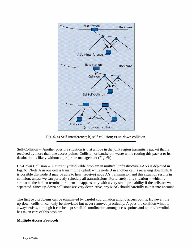
Fig. 6. a) Self-interference; b) self-collision; c) up-down collision.
Self-Collision -- Another possible situation is that a node in the joint region transmits a packet that isreceived by more than one access points. Collision or bandwidth waste while routing this packet to itsdestination is likely without appropriate management (Fig. 6b).
Up-Down Collision -- A currently unsolvable problem in multicell infrastructure LANs is depicted inFig. 6c. Node A in one cell is transmitting uplink while node B in another cell is receiving downlink. Itis possible that node B may be able to hear (receive) node A’s transmission and this situation results incollision, unless we can perfectly schedule all transmissions. Fortunately, this situation -- which issimilar to the hidden terminal problem -- happens only with a very small probability if the cells are wellseparated. Since up-down collisions are very destructive, any MAC should carefully take it into account.
The first two problems can be eliminated by careful coordination among access points. However, theup-down collision can only be alleviated but never removed practically. A possible collision windowalways exists, although it can be kept small if coordination among access points and uplink/downlinkhas taken care of this problem.
Multiple Access Protocols
Page 000010

We know that medium access control relies heavily on the features of the multiple access protocol andhence that the protocol is the core features of the multiple access protocol and hence that the protocol isthe core of medium access control for wireless LANs. Although there are many proposed multipleaccess protocols for wireless LANs, those meeting the features listed earlier can generally be classifiedas CSMA, polling, and TDMA (time division multiple access). We shall discuss their feasibility fromthe technical point of view only; time to the market is a concern that we ignore. The generalcharacteristics of these multiple access protocols are summarized. We start by discussing uplink multipleaccess, taking mobility into performance considerations.
Carrier Sense Multiple Access
Due to the popularity of Ethernet, CSMA is attractive to vendors and researchers [1, 6, 18]. CSMA is amember of the ALOHA family of protocols. ALOHA may be the first multiple/random access protocolthat has been applied to large-scale wireless networks. The original version, called pure ALOHA, has anunstable peak throughput around 18 percent. An improved version, called slotted ALOHA, requirestransmission to fall into synchronous slots and so reduces the possible collision duration. Slotsynchronization increases throughput to 36 percent. Again, this is an unstable peak value. Variousalgorithms, most based on distributed traffic estimation, have been proposed to make the networkoperate closer to peak throughput. However, it has proven difficult to implement such algorithmsprecisely. CSMA, which senses the status of channel before transmitting, is the simplest way to improveALOHA. As shown in many earlier investigations, CSMA demonstrates throughput increase for itsvarious versions [20, 21, 27]. Therefore, the IEEE 802.3 committee chose 1-persistent CSMA withcollision detection (CSMA/CD) as the MAC for wired LANs.
The success of CSMA/CD in Ethernet relies on the ease of sensing the carrier by measuring the currentor voltage in the cable. This is the primary reason that CSMA has been successfully applied in the wirednetworks even though it was originally designed for radio networks. Despite advances in technology,carrier sensing is still a major problem for radio networks due to the hidden terminal problem mentionedin Kleinrock and Tobagi’s pioneering paper [30-32]. Reliable carrier (or transmission) sensing isextremely difficult due to severe channel fading in indoor environments and the use of directionalantennas.
A second concern about CSMA is its instability. As shown in many research works, ALOHA andCSMA protocols are not stable [28]. This problem is seen by looking at delay curves. Delay increasesroughly in proportion to the offered load. However, near the peak throughput, the delay suddenlyincreases with a tremendous slope whose exact value depends on the total number of users. Thissituation makes peak throughput a meaningless number and requires networks to operate at low offeredload. This is the reason why 802.3 picked 1-persistent rather than non-persistent CSMA. Furthermore,measurements on practical Ethernets show operating throughput around only 30 to 35 percent rather the80 percent peak performance.
Finally, we would like to introduce another concern: spatial domain factors. Infrastructure LANstypically have a cellular structure, with each base station (access point) taking charge of one cell andwith adequate overlap with neighboring cells so that seamless service to mobile nodes is supported.Consequently, interference from other cells (most likely from neighboring cells) may influence MACprotocol operation, and thus introduce spatial domain effects. The possibility that this situation occurs isnot small in a severe, unpredictable fading channel such as indoor radio channels. The probability can beestimated from the system design and fading statistics. A good example to demonstrate this factor is
Page 000011

slotted ALOHA. According to the analysis in [12], we can clearly see the degradation due to variousdegrees of overlapping.
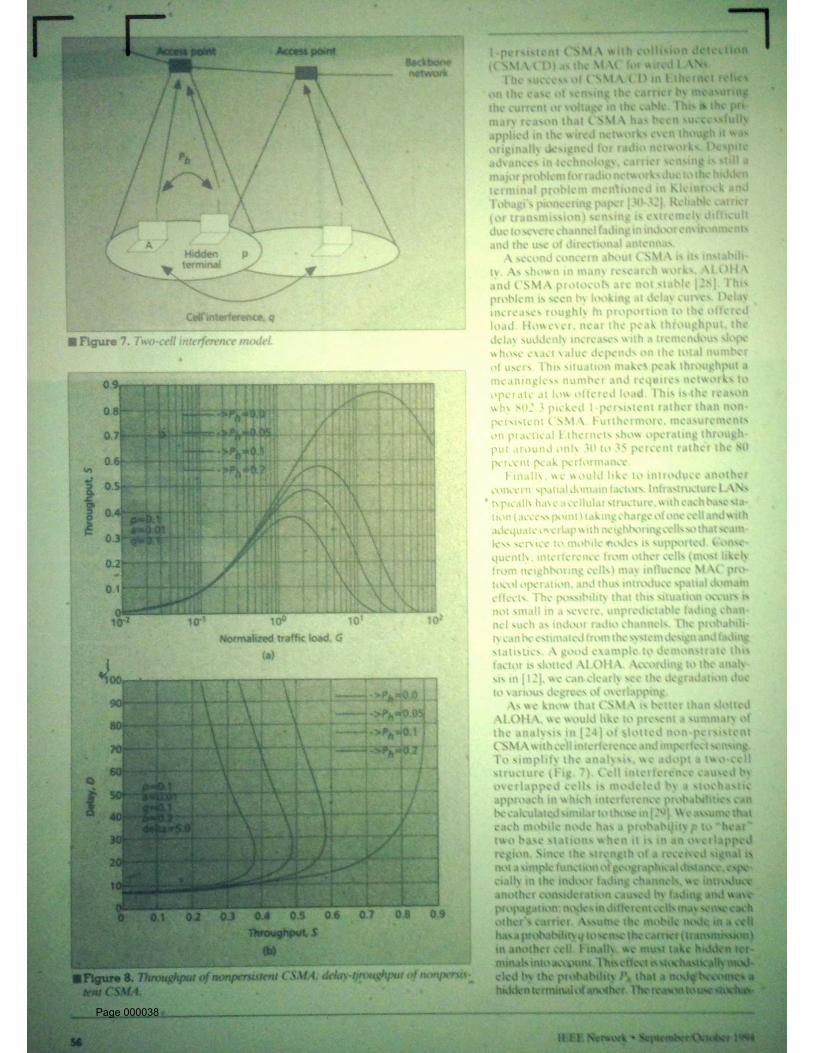
Fig. 7. Two-cell interference model.
As we know that CSMA is better than slotted ALOHA, we would like to present a summary of theanalysis in [24] of slotted non-persistent CSMA with cell interference and imperfect sensing. Tosimplify the analysis, we adopt a two-cell structure (Fig. 7). Cell interference caused by overlapped cellsis modeled by a stochastic approach in which interference probabilities can be calculated similar to thosein [29]. We assume that each mobile node has a probability p to "hear" two base stations when it is in anoverlapped region. Since the strength of a received signal is not a simple function of geographicaldistance, especially in the indoor fading channels, we introduce another consideration caused by fadingand wave propagation: nodes in different cells may sense each other’s carrier. Assume the mobile nodein a cell has a probability q to sense the carrier (transmission) in another cell. Finally, we must takehidden terminals into account. This effect is stochastically modeled by the probability Ph that a node
becomes a hidden terminal of another. The reason to use stochastic modeling is to best represent themobility and channel dynamics. The analytical results based on the above parametric model yieldnumerical results shown in Fig. 8. We can clearly observe that throughput is reduced to 40 to 45 percenteven with small Ph and p (say, 0.1); furthermore, we must keep in mind that, in practical wireless LANs,
interference may come from several cells. Because of this instability, CSMA may not be attractive forwireless networks.
Page 000012

Fig. 8. Throughput of nonpersistent CSMA; delay-tjroughput of nonpersistent CSMA.
To alleviate the hidden terminal problem and to increase reliability, a modification of CSMA -- CSMAwith collision avoidance (CSMA/CA) -- is popularly adopted. However, in general, unless associatedwith polling or constrained token passing or handshaking, it is believed useless since fading usually lastsfor a time equal to a few symbols at the data rate of LANs. The detailed reasoning is documented in[33]. The protocol that represents the current focus of the IEEE 802.11 committee, DFWMAC [1], usesCSMA/CA with a four-way handshake (Fig. 9) to combat indoor fading channels.
Page 000013
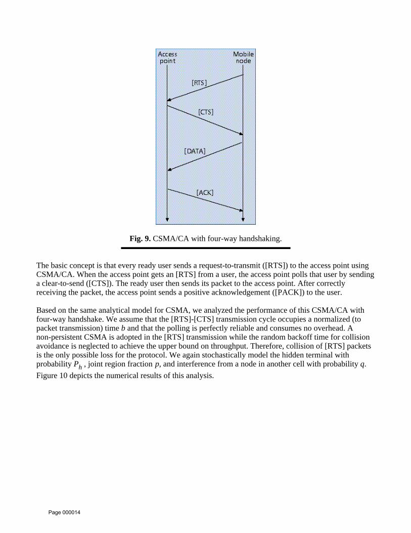
Fig. 9. CSMA/CA with four-way handshaking.
The basic concept is that every ready user sends a request-to-transmit ([RTS]) to the access point usingCSMA/CA. When the access point gets an [RTS] from a user, the access point polls that user by sendinga clear-to-send ([CTS]). The ready user then sends its packet to the access point. After correctlyreceiving the packet, the access point sends a positive acknowledgement ([PACK]) to the user.
Based on the same analytical model for CSMA, we analyzed the performance of this CSMA/CA withfour-way handshake. We assume that the [RTS]-[CTS] transmission cycle occupies a normalized (topacket transmission) time b and that the polling is perfectly reliable and consumes no overhead. Anon-persistent CSMA is adopted in the [RTS] transmission while the random backoff time for collisionavoidance is neglected to achieve the upper bound on throughput. Therefore, collision of [RTS] packetsis the only possible loss for the protocol. We again stochastically model the hidden terminal withprobability Ph , joint region fraction p, and interference from a node in another cell with probability q.
Figure 10 depicts the numerical results of this analysis.
Page 000014
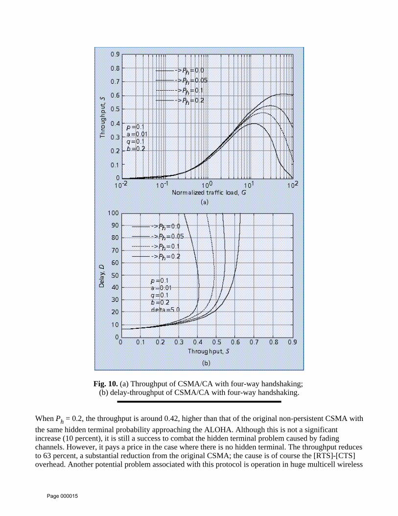
Fig. 10. (a) Throughput of CSMA/CA with four-way handshaking; (b) delay-throughput of CSMA/CA with four-way handshaking.
When Ph = 0.2, the throughput is around 0.42, higher than that of the original non-persistent CSMA with
the same hidden terminal probability approaching the ALOHA. Although this is not a significantincrease (10 percent), it is still a success to combat the hidden terminal problem caused by fadingchannels. However, it pays a price in the case where there is no hidden terminal. The throughput reducesto 63 percent, a substantial reduction from the original CSMA; the cause is of course the [RTS]-[CTS]overhead. Another potential problem associated with this protocol is operation in huge multicell wireless
Page 000015

LANs since the CSMA can be influenced by the interference. This will be discussed in a later section.
Polling
As previously discussed, distributed random access protocols do not perform well for multiple access inwireless networks. Our next idea is to consider some kind of centralized protocols. Token passingamong the mobile nodes is obviously not feasible since loss of token is very likely in fading channels,especially in wireless networks that do not guarantee a fully connected or well connected networktopology.
The next possibility is to use polling, since typical wireless networks have an infrastructure that connectsbase stations to serve mobile nodes under their coverage. Such centralized control over multiple accessprovides pretty reliable medium access control and robustness in the presence of fading and dynamicchannel characteristics. Therefore, it has been proposed as a possible frame structure for medium accesscontrol of wireless LANs [5, 23, 34]. However, it is hard for polling to achieve high efficiency [23] inspite of its good reliability. Base stations using polling typically require a hand-shaking procedure and astrict registration process for mobile nodes which implies a restricted roaming service. Also, even shortpackets for hand-shaking require an overhead for carrier and timing recovery. Such an overhead neveroccupies a short duration especially in the severe fading channels for which the systems are proposed.
Randomly Addressed Polling
It seems that a multiple access protocol for wireless LANs must be a compromise between centralizedand decentralized protocols to enjoy the advantages of both without suffering from their primarydisadvantages. Therefore, we proposed a family of new multiple access control protocols, calledrandomly addressed polling (RAP) [22, 25-26], which can be considered as a decentralized version ofpolling. RAP is based on the following ideas:
* A centralized protocol (such as polling) is reliable, especially for wireless networks thatusually operate in very unpredictable channels, though it requires constant monitoring of allnodes. * Constant monitoring all mobile nodes is not feasible in wireless networks. RAP requiresthe knowledge of the "random address(es)" of only active users (rather than all users).
The operation of RAP, designed for the infrastructure in Fig. 1, is summarized as follows:
Step 1 -- When a base station is ready to collect uplink packets, it broadcasts a [READY] message to allmobile nodes in its coverage area. (The [READY] indication may be piggy-backed on a previousmessage, thereby avoiding an extra transmission.)
Note that, in general, due to the fast changing environment [3], the base station may not know themobile nodes within its coverage. For RAP, the base station needs to know only the active nodesseeking uplink communication.
Step 2a -- Each active mobile node that intends to transmit generates a random number from the set IR =
{0, 1, . . . , P - 1}. This random number may be generated in advance before the reception of [READY].
Step 2b -- All active mobile nodes simultaneously transmit their dom numbers. Transmission must be
Page 000016

simultaneous and orthogonal; for example, by orthogonal codes such as those for code division multipleaccess (CDMA), or by different frequencies. Furthermore, random number exchange can be divided intoL identical "stages," where each stage involves the generation and exchange of random numbers asdescribed above.
Step 2c -- In general, a mobile node may transmit its random number Q times at each stage. The basestation may use some sort of voting policy to decide the correctly transmitted random number(s). Withthe error-free transmission assumed in this paper, Q = 1 is enough. In case the base station can notrecognize certain random number(s), it assumes no reception.
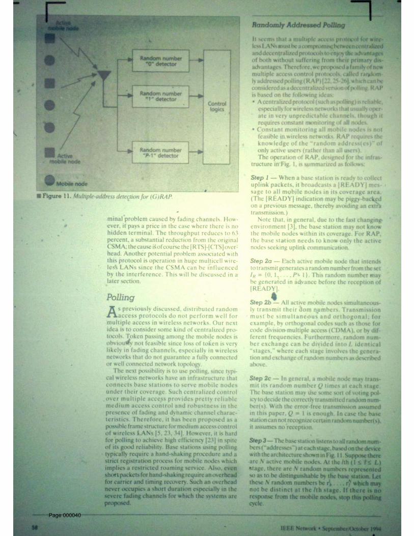
Step 3 -- The base station listens to all random numbers ("addresses") at each stage, based on the devicewith the architecture shown in Fig. 11. Suppose there are N active mobile nodes. At the lth (1 l L) stage,there are N random numbers represented so as to be distinguishable by the base station. Let these Nrandom numbers be r1
l, . . . , r1N which may not be distinct at the lth stage. If there is no response from
the mobile nodes, stop this polling cycle.
Fig. 11. Multiple-address detection for (G)RAP.
Step 4 -- Among these L stages, suppose that the base station received the largest number of distinctrandom addresses at the l*th stage. Denote these numbers as R1 < . . . < RN*. Then the base station pollsaccording to the mobile nodes’ l*th random numbers. When the base station polls mobile nodes with Rr
(1 r N*) at the l*th stage, the mobile nodes who sent the random number at the l* th stage transmitspacket(s) to the base station. Collision is possible since there might be two mobile nodes sending thesame random number. If N = N*, no collision exists.
Step 5 -- If the base station successfully/unsuccessfully receives the packet from any mobile node, itsends a positive/negative acknowledge ([PACK]/[NACK]) right away before polling the next one(s). Ifthe mobile node receives [PACK], it removes the packet from its buffer. Otherwise, the mobile node(s)
Page 000017

keep the packet(s) for future polling. After all scheduled transmissions, the base station re-polls again(i.e., repeats steps 1-4). Although re-polling may allow new active mobile nodes to join, we temporarilyassume that no new active mobile node is allowed to join re-polling for the simplicity of analysis andcongestion control.
As the downlink (from the network to mobile nodes) transmission is typically done by broadcasting, weconcentrate only on the uplink multiple access protocol. The complete description of RAP withimplementation concerns can be found in [25, 34]. Note that RAP requires no handoff for users roamingfrom one cell to another cell (Fig. 12). A mobile node can send packet(s) to all reachable base stations.If any form of handoff is needed for the purpose of network management, handoff can be initiatedcompletely by mobile nodes.
Fig. 12. No handoff for (G)RAP.
Page 000018

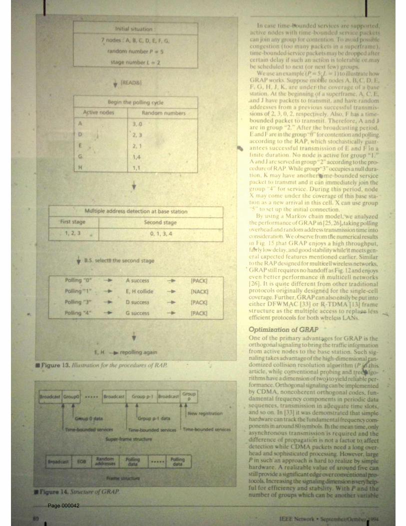
Fig. 13. Illustration for the procedures of RAP.
We use an example to illustrate the procedures of RAP. Figure 13 depicts this example. Suppose thereare mobile nodes A, B, C, D, E, F, G, and H, under the coverage of a base station (or an access point).We choose P = 5 and L = 2 as the parameters of RAP. At the beginning of the polling cycle, only A, D,E, G, and H, have packets to transmit. When [READY] is received by all of these active nodes, randomnumbers are generated by them according to step 2.
A: 3,0 D: 2,3 E: 2,1 G: 1,4 H: 1,1
The base station collects the random addresses by proper orthogonal signaling and detection. At the firststage, the base station recognizes random addresses 3, 2, and 1. At the second stage, the base stationrecognizes random addresses 0, 3, 1, and 4. Therefore, the base station polls mobile nodes according tothe random addresses of the second stage. When the base station polls "0," A sends its packet. Under theerror-free assumption, A will receive [PACK] from the base station to complete its uplink datatransmission, as will D and G. However, when the base station polls "1" of the second stage, packetsfrom E and H collide. Not considering the capture effect (since a good power control is assumed), both
Page 000019
E and H will receive [NACK] and go to the repolling cycle. Of course, if we consider the possibility ofchannel errors, A, D, and G, may also receive [NACK] and join the repolling.
Group Randomly Address Polling
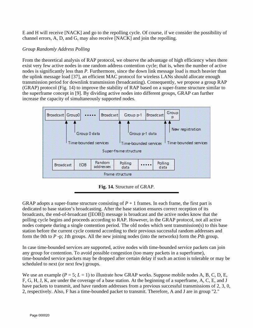
From the theoretical analysis of RAP protocol, we observe the advantage of high efficiency when thereexist very few active nodes in one random address contention cycle; that is, when the number of activenodes is significantly less than P. Furthermore, since the down link message load is much heavier thanthe uplink message load [37], an efficient MAC protocol for wireless LANs should allocate enoughtransmission period for downlink transmission (broadcasting). Consequently, we propose a group RAP(GRAP) protocol (Fig. 14) to improve the stability of RAP based on a super-frame structure similar tothe superframe concept in [9]. By dividing active nodes into different groups, GRAP can furtherincrease the capacity of simultaneously supported nodes.
Fig. 14. Structure of GRAP.
GRAP adopts a super-frame structure consisting of P + 1 frames. In each frame, the first part isdedicated to base station’s broadcasting. After the base station ensures correct reception of itsbroadcasts, the end-of-broadcast ([EOB]) message is broadcast and the active nodes know that thepolling cycle begins and proceeds according to RAP. However, in the GRAP protocol, not all activenodes compete during a single contention period. The old nodes which sent transmission(s) to this basestation before the current cycle contend according to their previous successful random addresses andform the 0th to P -p; 1th groups. All the new joining nodes (into the networks) form the Pth group.
In case time-bounded services are supported, active nodes with time-bounded service packets can joinany group for contention. To avoid possible congestion (too many packets in a superframe),time-bounded service packets may be dropped after certain delay if such an action is tolerable or may bescheduled to next (or next few) groups.
We use an example (P = 5; L = 1) to illustrate how GRAP works. Suppose mobile nodes A, B, C, D, E,F, G, H, J, K, are under the coverage of a base station. At the beginning of a superframe, A, C, E, and Jhave packets to transmit, and have random addresses from a previous successful transmissions of 2, 3, 0,2, respectively. Also, F has a time-bounded packet to transmit. Therefore, A and J are in group "2."
Page 000020

After the broadcasting period, E and F are in the group "0" for contention and polling according to theRAP, which stochastically guarantees successful transmission of E and F in a finite duration. No node isactive for group "1." A and J are served in group "2" according to the procedure of RAP. While group"3" occupies a null duration, K may have another time-bounded service packet to transmit and it canimmediately join the group "4" for service. During this period, node X may come under the coverage ofthis base station as a new arrival in this cell. X can use group "5" to set up the initial connection.
Fig. 15. a) Throughput of GRAP (L = 2, P = 5); b) delay of GRAP (L = 2, P = 5).
Page 000021

By using a Markov chain model, we analyzed the performance of GRAP in [25, 26], taking pollingoverhead and random address transmission time into consideration. We observe from the numericalresults in Fig. 15 that GRAP enjoys a high throughput, fairly low delay, and good stability while it meetsgeneral expected features mentioned earlier. Similar to the RAP designed for multicell wirelessnetworks, GRAP still requires no handoff as Fig. 12 and enjoys even better performance in multicellnetworks [26]. It is quite different from other traditional protocols originally designed for the single-cellcoverage. Further, GRAP can also easily be put into either DFWMAC [33] or R-TDMA [13] framestructure as the multiple access to replace less efficient protocols for both wireless LANs.
Optimization of GRAP
One of the primary advantages for GRAP is the orthogonal signaling to bring the traffic informationfrom active nodes to the base station. Such signaling takes advantage of the high-dimensionalrandomized collision resolution algorithm (P in this article, while conventional probing and treealgorithms have a dimension of two) to yield reliable performance. Orthogonal signaling can beimplemented by CDMA, noncoherent orthogonal codes, fundamental frequency components in periodicdata sequences, transmission in adequate time slots, and so on. In [33] it was demonstrated that simplehardware can track the fundamental frequency components in around 80 symbols. In the mean time,only asynchronous transmission is required and the difference of propagation is not a factor to affectdetection while CDMA packets need a long overhead and sophisticated processing. However, large P insuch an approach is hard to realize by simple hardware. A realizable value of around five can stillprovide a significant edge over conventional protocols. Increasing the signaling dimension is veryhelpful for efficiency and stability. With P and the number of groups which can be another variable tooptimize, it should be good enough. Further improvement is possible by changing the L-stage scheme toa PL-dimension product address space.
General Efficient and Reliable Multiple Access
We have thus far discussed the general problem and expected features for the MAC design of wirelessLANs and the core -- multiple access protocols -- with appropriate analysis. In the following, a moregeneral and high level view of the problem is presented.
Procedure for Reliable Multiple Access
Looking at CSMA/CA with four-way handshaking, GRAP, and other proposals for IEEE 802.11, wemay conclude that a reliable multiple access protocol tries to accomplish the following procedures [34]:
1) An invitation for contention, which may not be done explicitly. 2) A contention scheme, such as ALOHA, CSMA, orthogonal signaling in GRAP, etc. 3) Coordination of packet transmission; e.g., by polling. 4) Uplink packet transmission. 5) Acknowledgement to mobile nodes.
Figure 16 depicts this scenario. For the case of CSMA/CA with four-way handshaking, procedures 2-5have been specified while procedure 1 is taken care of by timing synchronization. For the case ofGRAP, procedures 2-5 are taken while procedure 1 is done implicitly. With perfect synchronization andcell isolation, IBM’s R-TDMA (reserved time division multiple access) implicitly executes procedure 1
Page 000022

and combines procedures 3-5 in the TDMA scheme.
Fig. 16. General reliable procedure for multiple access.
The rationale to adopt the above general procedures can be explained by the concept of dynamicnetwork topology and features of wireless links. All mobile nodes in a cell have one common feature:the ability to reliably communicate with the base station (or access point in general). Communication(thus carrier/transmission sensing) among nodes in general, not to mention nodes in other cell(s), is notreliable, and thus neither is transmission/carrier sensing. To avoid potential "interference" fromdistributed multiple access protocols, the base station is the only reliable candidate to control thechannel. On the other hand, the high efficiency (in terms of channel utilization and power consumption)distributed contention protocols are preferred. Among coordination of access points such as basestations, after procedure 1, a contention procedure for a base station to collect traffic information isgenerally needed. Then, the reliable uplink data transmission is achieved by polling.
Reservation and Superframe
If time-bounded services are needed, reservation is obviously the simplest way. The typical approach isto form a superframe structure based on either absolute timing or relative timing and to have someframe(s) in the superframes serve these time-bounded services [2]. Part of the superframe is reserved fortime-bounded services or continuous data services. Currently, almost all MAC protocols have this kindof function. R-TDMA may have been be the first MAC to introduce the complete concepts ofreservation and superframe into wireless LANs, and now both concepts are widely applied in variousMAC protocols [1, 9, 22]. R-TDMA uses a fixed-length superframe structure with three segments:downlink broadcasting, uplink reservation, and uplink contention with a multiple access protocol looselydefined as anyone described in previous sections. The major drawbacks of R-TDMA are 1) the lack of
Page 000023

flexibility in time slots based on the absolute timing implies complicated synchronization throughwireless links, and 2) the requirement of cell isolation. Recall that wireless LANs operate at multipledata rates or symbol rates of physical layer transmission which implies different sizes of time slots at thesame packet length. Fixed duration of time slots actually requires knowledge of the physical layer.However, the three-segment superframe structure and the client-server service concept benefit a lot inthe direction of MAC design. Astute readers may note that the R-TDMA is conceptually similar toPRMA (packet reservation multiple access) proposed by Goodman [13] in frame structure or evenearlier a paper by Lam [35].
Multicell Wireless LANs Is Interference-Limited
Due to the collocation problem and potential large-scale multicell networks, interference can be asserious a trouble for wireless LANs as the limitation of frequency channels. As an example, the directsequence PHY at 2.4 GHz with 83.5-MHz bandwidth is likely to transmit 2 Mb/s with 11-Mc/s chiprate. The 6-dB bandwidth is well over 20 MHz and the total available channel number is 3. Since theradio propagation is very changeable, we may expect interference from quite a few cells away if theCSMA is used. That is, there are a lot more interference sources than our two-cell analysis shows,including more possible hidden terminals. That is the reason why CSMA/CA with four-wayhandshaking is needed for the practical operation of wireless LANs in this case. As an example, the totalnumber of neighboring cells two cell-diameters away or less is 18. Consequently, six cells on averagemay interfere with a particular cell if direct sequence spread spectrum transmission at the 2.4 GHz ISMband is used.
Potential IEEE 802.11 MAC Architecture
Currently, the IEEE 802.11 standard draft is not available but is expected for letter balloting inNovember 1994. The MAC architecture is likely to look as Fig. 17. The MAC consists of severalfunctional blocks: MAC-LLC service interface; MAC state machine; MAC management state machine;MAC management information base.
Page 000024

Fig. 17. Potential IEEE 802.11 MAC architecture block diagram.
The MAC-LLC service interface shall accept the MAC service requests from higher layers anddistribute these requests to either the MAC data service or the MAC management service. The MACstate machine shall provide the sequencing for various services supported by the wireless LANs. TheMAC management state machine shall provide the protocol sequencing for association andre-association, access to the MAC management information base, timing synchronization, powermanagement, authentication, etc. The MAC management information base shall provide storage andaccess of all information to properly manage the MAC.
Fig. 18. Potential IEEE 802.11 (uplink) super-frame structure.
The MAC should generally provide distributed coordination function and point coordination function asDFWMAC suggests [1]. Distributed coordination function can be considered as the multiple access partof the MAC. Point coordination function should be on top of the distributed coordination function tocreate contention-free access. A superframe structure with contention and contention-free parts shall beadopted as shown in Fig. 18. There are a lot of details still to be determined at this moment. However,based on the structure of DFWMAC, the possible features include a beacon signaling from access pointsto synchronize the clocks in the mobile nodes, cell isolation when the point coordination function is
Page 000025

used, and fragmentation/polarization of packets.
Conclusions
The core of the design of a MAC suitable for wireless LANs is the multiple access protocol. The need toovercome user mobility and dynamic channel characteristics introduces a new point of view to evaluateMAC design and point the way toward a highly efficient wireless LAN to serve mobile users.
The need to overcome mobility introduces a new point of view to evaluate the MAC design embeddedin the traditional uplink multiple access. We can see the advantages of the GRAP protocol -- the firstmultiple access protocol designed for the multicell wireless networks -- to meet the LAN requirementseven with imperfect power control [33]. We also believe that GRAP is a good candidate for otherapplications of small-cell type wireless networks to serve mobile users. Applying GRAP in integratedservice wireless networks and in unreliable channels is being heavily studied at the National Tsing HuaUniversity. An experimental wireless network employing GRAP has been designed and simulatedtoward real implementation.
This article points the way toward a highly efficient wireless local area network to serve mobilecomputing users. With concise description of its MAC underway, a new wireless LAN standard IEEE802.11 is expected to be available by the end of 1994. Mobile computing served by much higherbandwidth wireless LANs than currently available modem-speed wireless connection shall bring a newscenario to our information society.
Acknowledgements
The author thanks D. Duchamp, C. S. Chang, and the reviewers for their help to improve thepresentation of this paper. He also appreciates the National Bureau of Standards of the Ministry ofEconomic Affairs to support his participation of the IEEE 802.11 activities, and the National ScienceCouncil to support the research in this topic.
References
[1] W. Diepstraten, G. Ennis, P. Belanger, "Distributed Foundation Wireless Medium Access Control,"IEEE P802.11-93/190.
[2] R. LaMaire, A. Krishna, H. Ahmadi, "Analysis of A Wireless MAC Protocol with Client-ServerTraffic" Proc. IEEE INFOCOM, pp. 429-438, 1993.
[3] C. C. Huang and R. Khayata, "Delay Spread and Channel Dynamics Measurement at ISM Bands,"Proc. of the ICC’92.
[4] J. Cheah, "A Proposed Architecture and Access Protocol Outline for the IEEE 802.11 Radio LANStandards, Part II," IEEE Documentation P802.11/91-54.
[5] Z. Zhang and A. Acampora, "Performance of a Modified Polling Strategy for Broadband WirelessLANs in a Harsh Fading Environment," Proc. of the IEEE GLOBECOM ’91, pp.1141-1146.
[6] I. Vukovic and K. Vastola, "Throughput Analysis of Asynchronous CSMA Protocols on Star-Like
Page 000026

LAN Topology," Proc. of the ICC ’92.
[7] C. Rypinski, "Limitations of CSMA in 802.11 Radio LAN Applications," IEEE DocumentationP802.11/91-46.
[8] D. Buchholz and L. Hamilton, "Comments on CSMA," IEEE P802.11/91-49.
[9] K. S. Natarajan, C. C. Hwang, and D. Bantz, "Medium Access Control for Radio LANs," IEEEDocumentation P802.11/91-74.
[10] Y. Yakiyasu, "High Performance Access Control Method for Base Station-Controlled Systems,"IEEE Documentation P802.11/92-71.
[11] R. Krishnamoorthy, "On Simulating MAC Protocols," IEEE P802.11/92-52.
[12] C. Y. Ko, K. C. Chen, and C. C. Lu, "Performance of Slotted ALOHA in Multiple Joint Cell ofWireless Networks," Proc. Int’l Symposium on Personal, Indoor and Mobile Radio Communications,Boston, 1992.
[13] D. J. Goodman, "Cellular Packet Communications," IEEE Trans. on Commun., vol. 38, no. 8,pp.1272-1280, Aug. 1990.
[14] J. M. Holtzman, "Adaptive Measurement Intervals for Handoffs," Proc. ICC ’92, pp. 1,031-1,036,Chicago, 1992.
[15] W. Lee, Mobile Cellular Telecommunications Systems, (Singapore: McGraw-Hill, 1990).
[16] K. Zhang and K. Pahlavan, "CSMA Local Radio Networks With BPSK Modulation in RayleighFading Channels," Electron. Lett., vol. 26, pp. 1655-1656, 1990.
[17] F. Kuperus and J. Arnbak, "Packet Radio in a Rayleigh Channel," Electron. Lett., vol. 18, pp.506-507, 1982.
[18] P. Jacquet and P. Muhlethaler, "CSMA-Ratio Mobile MAC Proposal," IEEE P802.11/93- 99.
[19] Z. Haas, C.-L. I, "On Handoffs in Packetized Wireless Systems," Proc. IEEE Globecom, Houston,1993.
[20] F. Tobagi and L. Kleinrock, "Packet Switching in Radio Channels: Part I - Carrier Sense MultipleAccess Modes and Their Throughput Delay Characteristics," IEEE Trans. on Commun., vol. 23, no. 12,pp.1400-1416, Dec. 1975.
[21] F. Tobagi, L. Kleinrock, "Packet Switching in Radio Channels: Part II -- The Hidden TerminalProblem in CSMA and Busy-Tone Solution," IEEE Trans. on Commun., vol. 23, pp. 1417-1433.
[22] K. C. Chen, "An Update Version of GRAP," IEEE P802.11/93-106.
[23] C. Heide, "CODIAC Protocol -- Centralized or Distributed Integrated Access Control," IEEE
Page 000027

P802.11/93-54.
[24] W. L. Huang and K. C. Chen, "Performance of Nonpersistent CSMA with OverlappedCell-Coverage and Hidden Terminals in Wireless Networks," submitted for publication.
[25] K. C. Chen and C. H. Lee, "RAP - A Novel Medium Access Control Protocol for Wireless DataNetworks," Proc. IEEE GLOBECOM, 1993.
[26] K. C. Chen and C. H. Lee, "Group Randomly Addressed Polling for Wireless Data Networks,"Proc. IEEE ICC, 1994.
[27] F. A. Tobagi and V. B. Hunt, "Performance Analysis of Carrier Sense Multiple Access withCollision Detection" Computer Networks, vol. 4, pp. 245-259, Oct-Nov. 1980.
[28] J. S. Meditch and C.-T.A. Lea,"Stability and Optimization of the CSMA and CSMA/CD Channel,"IEEE Trans. on Commun., vol. COM-31, no. 6, pp. 763-774, June 1983.
[29] C. T. Lau and C. Leung,"Capture Models for Mobile Packet Radio Networks," IEEE Trans. onCommun., vol. COM-40, pp. 917-925, May 1992.
[30] S. G. Glisic, R. Rao, and L. Milstein, "The Effect of Imperfect Carrier Sensing on NonpersistentCSMA," Proc. ICC ’90, paper 332.4.
[31] S. G. Glisic, "1-Persistent Carrier Sense Multiple Access in Radio Channel With Imperfect CarrierSensing," IEEE Trans. Commun., vol COM-39, pp. 458-464, March 1991.
[32] S. G. Glisic et al., "Channel State PDF and Through- put Analysis for Multichannel CSMASystems With Imperfect Carrier Sensing," ICCS/ISITA’92, Singapore, pp. 681-685, 1992.
[33] K. C. Chen, "Enhancement of Multiple Access for DFWMAC," IEEE P802.11/94-14.
[34] K. C. Chen and C. P. Tzeng, "On the GRAP -- A Proposed MAC Protocol," IEEE DocumentationP802.11/93-39.
[35] S. S. Lam, "Packet Broadcast Networks - A Performance Analysis of the R-ALOHA Protocol,"IEEE Trans. on Computers, vol.29, no.7, pp. 596-603, July 1980.
[36] C. Rypinski, personal communication.
[37] P.D. Hortensius, personal communication.
Biography
Kwang-Cheng Chen [SM ’93] received a B.S. from the National Taiwan University, M.S.and Ph.D. degrees from the University of Maryland at College Park, in 1983, 1987, and1989, all in electrical engineering. After working with the SSE, COMSAT, and IBM’s T. J.Watson Research Center, from 1987-1991, he returned to Taiwan and now is an associateprofessor at the Department of Electrical Engineering, National Tsing Hua University,
Page 000028

Hsinchu, Taiwan. He is actively involved in the R & D of wireless communication systemsand networks, and participating IEEE conference organization and journal editorship. He hasbeen a voting member of the IEEE 802.11 since 1991 and is authoring a book on wirelessLANs to be published in 1995. His e-mail address is [email protected].
1 Industrial, scientific, and medical.(Return)
Page 000029

Page 000030

Page 000031

Page 000032

Page 000033

Page 000034

Page 000035
Page 000036
Page 000037
Page 000038

Page 000039
Page 000040

Page 000041
Page 000042

Page 000043

Page 000044

Page 000045