media.digikey.com sheets/texas instruments pdfs... · important notice texas instruments...
TRANSCRIPT

Safety Manual for RM57x Hercules ARM SafetyMCUs
User's Guide
Literature Number: SPNU575AMay 2014–Revised September 2016

2 SPNU575A–May 2014–Revised September 2016Submit Documentation Feedback
Copyright © 2014–2016, Texas Instruments Incorporated
Table of Contents
Contents
1 Introduction ........................................................................................................................ 82 Hercules RM57x Product Overview....................................................................................... 10
2.1 Targeted Applications .................................................................................................. 112.2 Product Safety Constraints ............................................................................................ 12
3 Hercules Development Process for Management of Systematic Faults ..................................... 133.1 TI Standard MCU Automotive Development Process ............................................................. 143.2 TI MCU Automotive Legacy IEC 61508 Development Process .................................................. 153.3 Yogitech fRMethodology Development Process ................................................................... 153.4 Hercules Enhanced Safety Development Process ................................................................. 15
4 Hercules Product Architecture for Management of Random Faults........................................... 184.1 Safe Island Philosophy and Architecture Partition to Support Safety Analysis (FMEA/FMEDA) ............ 184.2 Identification of Parts/Elements ....................................................................................... 194.3 Management of Family Variants ...................................................................................... 204.4 Operating States ........................................................................................................ 204.5 Management of Errors ................................................................................................. 22
5 System Integrator Recommendations ................................................................................... 235.1 System Integrator Activities ........................................................................................... 235.2 Hints for Performing Dependent/Common Cause Failure Analysis Including the Hercules MCU ........... 255.3 Hints for Improving Independence of Function/Co-Existence of Function When Using the Hercules MCU 255.4 Support for System Integrator Activities ............................................................................. 25
6 Brief Description of Elements .............................................................................................. 266.1 Power Supply ........................................................................................................... 266.2 Power Management Module (PMM) ................................................................................. 266.3 Clocks .................................................................................................................... 276.4 Reset ..................................................................................................................... 276.5 System Control Module ................................................................................................ 286.6 Error Signaling Module (ESM) ....................................................................................... 296.7 CPU Subsystem ........................................................................................................ 296.8 Primary Embedded Flash ............................................................................................. 316.9 Flash EEPROM Emulation (FEE) .................................................................................... 326.10 Primary Embedded SRAM ............................................................................................ 336.11 CPU Interconnect Subsystem......................................................................................... 346.12 Peripheral Interconnect Subsystem .................................................................................. 356.13 Peripheral Central Resource 1 (PCR1) .............................................................................. 356.14 Peripheral Central Resource 2 (PCR2) .............................................................................. 366.15 Peripheral Central Resource 3 (PCR3) .............................................................................. 366.16 EFuse Static Configuration ............................................................................................ 376.17 OTP Static Configuration .............................................................................................. 376.18 I/O Multiplexing Module (IOMM)...................................................................................... 386.19 Vectored Interrupt Module (VIM) ..................................................................................... 386.20 Real Time Interrupt (RTI) .............................................................................................. 39

www.ti.com
3SPNU575A–May 2014–Revised September 2016Submit Documentation Feedback
Copyright © 2014–2016, Texas Instruments Incorporated
Contents
6.21 Direct Memory Access (DMA) ........................................................................................ 406.22 High-End Timer (N2HET), HET Transfer Unit (HTU) .............................................................. 406.23 Multi-Buffered Analog-to-Digital Converter (MibADC) ............................................................. 426.24 Enhanced Pulse Width Modulators (ePWM) ........................................................................ 426.25 Enhanced Capture (eCAP) ............................................................................................ 436.26 Enhanced Quadrature Encoder Pulse (eQEP) ..................................................................... 446.27 Multi Buffered Serial Peripheral Interface (MibSPI) ................................................................ 456.28 Inter-Integrated Circuit (I2C) .......................................................................................... 466.29 Serial Communication Interface (SCI) ............................................................................... 466.30 Local Interconnect Network (LIN) .................................................................................... 476.31 Controller Area Network (DCAN) ..................................................................................... 486.32 General-Purpose Input/Output (GIO) ................................................................................ 496.33 Ethernet .................................................................................................................. 496.34 External Memory Interface (EMIF) ................................................................................... 506.35 JTAG Debug, Trace, Calibration, and Test Access ................................................................ 516.36 Cortex-R5F Central Processing Unit (CPU) Debug and Trace ................................................... 516.37 Data Modification Module (DMM)..................................................................................... 516.38 RAM Trace Port Interface (RTP) ..................................................................................... 516.39 Parameter Overlay Module (POM) ................................................................................... 526.40 Error Profiling Controller (EPC) ....................................................................................... 526.41 Temperature Sensor ................................................................................................... 53
7 Brief Description of Diagnostics........................................................................................... 547.1 1oo2 Software Voting Using Secondary Free Running Counter ................................................. 547.2 Bit Error Detection ...................................................................................................... 547.3 Bit Multiplexing in FEE Memory Array ............................................................................... 547.4 Bit Multiplexing in Flash Memory Array .............................................................................. 547.5 Bit Multiplexing in Primary SRAM Memory Array................................................................... 547.6 Bit Multiplexing in Peripheral SRAM Memory Array................................................................ 547.7 CPU Illegal Operation and Instruction Trapping ................................................................... 557.8 Logic Built In Self-Test (LBIST) ...................................................................................... 557.9 Logic Built In Self-Test (LBIST) Auto-Coverage .................................................................... 567.10 CPU Lockstep Compare .............................................................................................. 567.11 VIM Lockstep Compare ............................................................................................... 567.12 Lockstep Comparator Self-Test....................................................................................... 567.13 CPU Online Profiling Using the Performance Monitoring Unit.................................................... 567.14 CPU Memory Protection Unit (MPU)................................................................................. 577.15 CRC Auto-coverage .................................................................................................... 577.16 CRC in Message........................................................................................................ 577.17 DCAN Acknowledge Error Detection................................................................................. 577.18 DCAN Form Error Detection .......................................................................................... 577.19 DCAN Stuff Error Detection ........................................................................................... 577.20 DCAN Protocol CRC in Message..................................................................................... 577.21 Disable the DMM Pin Interface ....................................................................................... 587.22 Disable the RTP Pin Interface ........................................................................................ 587.23 Dual Clock Comparator (DCC)........................................................................................ 587.24 Autoload Self-Test ...................................................................................................... 587.25 Efuse Autoload Self-Test Auto-Coverage ........................................................................... 587.26 EFuse ECC .............................................................................................................. 587.27 EFuse ECC Logic Self-Test ........................................................................................... 58

www.ti.com
4 SPNU575A–May 2014–Revised September 2016Submit Documentation Feedback
Copyright © 2014–2016, Texas Instruments Incorporated
Contents
7.28 eQEP Quadrature Watchdog.......................................................................................... 587.29 eQEP Software Test of Quadrature Watchdog Functionality ..................................................... 597.30 Error Trapping - IOMM ................................................................................................. 597.31 Error Trapping (including Peripheral Slave Error Trapping) - L2/L3 Interconnect.............................. 597.32 Ethernet Alignment Error Detection .................................................................................. 597.33 Ethernet Physical Layer Fault ........................................................................................ 597.34 External Monitoring of Warm Reset (nRST) ........................................................................ 597.35 External Monitoring via ECLK......................................................................................... 597.36 External Voltage Supervisor........................................................................................... 607.37 External Watchdog ..................................................................................................... 607.38 FEE Contents Check by Hardware CRC ............................................................................ 607.39 FEE Data ECC .......................................................................................................... 607.40 FEE Sector Protection ................................................................................................. 607.41 Flash Address and Control Bus Parity ............................................................................... 617.42 Flash Contents Check by Hardware CRC........................................................................... 617.43 Flash ECC ............................................................................................................... 617.44 Flash Hard Error Cache and Livelock................................................................................ 617.45 Flash Sector Protection ................................................................................................ 627.46 Flash Wrapper Address ECC ......................................................................................... 627.47 Flash Wrapper Diag Mode 5 Test .................................................................................... 627.48 Flash Wrapper Diag Mode 7 Test .................................................................................... 627.49 Glitch Filtering on nRST and nPORRST ............................................................................ 627.50 Hardware CRC Check of External Memory ......................................................................... 627.51 Hardware CRC Check of OTP Contents ............................................................................ 627.52 Hardware Disable of JTAG Port ...................................................................................... 627.53 Information Redundancy Techniques ................................................................................ 637.54 Information Redundancy Techniques - CPU Specific ............................................................. 637.55 Information Redundancy Techniques - DCAN Specific............................................................ 637.56 Information Redundancy Techniques - DMA Specific ............................................................. 637.57 Information Redundancy Techniques - N2HET Specific .......................................................... 637.58 Internal Voltage Monitor (VMON) .................................................................................... 647.59 Internal Watchdog ...................................................................................................... 647.60 IOMM Master ID Filtering .............................................................................................. 647.61 LIN Checksum Error Detection ....................................................................................... 647.62 LIN No-Response Error Detection.................................................................................... 647.63 LIN Physical Bus Error Detection..................................................................................... 657.64 LIN / SCI Bit Error Detection .......................................................................................... 657.65 LIN / SCI Frame Error Detection ..................................................................................... 657.66 LIN / SCI Overrun Error Detection.................................................................................... 657.67 Locking Mechanism for Control Registers........................................................................... 657.68 Lockout of JTAG Access Using AJSM............................................................................... 657.69 Low Power Oscillator Clock Detector (LPOCLKDET).............................................................. 657.70 Memory Protection Unit (MPU) for Non-CPU Bus Masters ...................................................... 657.71 MibADC Calibration .................................................................................................... 667.72 MibADC Information Redundancy Techniques ..................................................................... 667.73 MibADC Input Self-Test................................................................................................ 667.74 MibSPI/SPI Data Length Error Detection............................................................................ 667.75 MibSPI/SPI Data Overrun Detection ................................................................................. 66

www.ti.com
5SPNU575A–May 2014–Revised September 2016Submit Documentation Feedback
Copyright © 2014–2016, Texas Instruments Incorporated
Contents
7.76 MibSPI/SPI Slave Desync Detection ................................................................................. 667.77 MibSPI/SPI Slave Timeout Detection ................................................................................ 667.78 Monitoring by Second N2HET ........................................................................................ 677.79 Monitoring by eCAP or N2HET ....................................................................................... 677.80 Non-Privileged Bus Master Access .................................................................................. 677.81 OTP Autoload ECC..................................................................................................... 677.82 Parity in Message....................................................................................................... 677.83 Periodic Hardware CRC Check of OTP Contents.................................................................. 677.84 PCR Access Management: Protection Mode and MasterID Filtering............................................ 677.85 Periodic Hardware CRC Check of SRAM Contents................................................................ 687.86 Periodic Software Read Back of Static Configuration Registers ................................................ 687.87 Peripheral SRAM Parity................................................................................................ 687.88 Peripheral Memory ECC ............................................................................................... 687.89 PLL Slip Detector ....................................................................................................... 687.90 Primary SRAM Address and Control Bus Parity.................................................................... 687.91 Primary SRAM Data and ECC Storage in Multiple Physical Banks per Logical Address..................... 697.92 Primary SRAM Correctable ECC Profiling .......................................................................... 697.93 ECC on Cache RAM ................................................................................................... 697.94 Primary SRAM Data ECC ............................................................................................. 697.95 Primary SRAM Wrapper Redundant Address Decode ............................................................ 697.96 Primary SRAM Hard Error Cache and Livelock .................................................................... 707.97 Privileged Mode Access and Multi-Bit Enable Keys for Control Registers...................................... 707.98 PBIST Check of Primary or Module SRAM ......................................................................... 707.99 PBIST Auto-coverage .................................................................................................. 717.100 Power Domain Inactivity Monitor ..................................................................................... 717.101 PBIST Test of Parity Bit Memory..................................................................................... 717.102 PBIST Test of ECC Bit Memory ...................................................................................... 717.103 Lockstep PSCON....................................................................................................... 717.104 Redundant Address Decode Self-Test .............................................................................. 717.105 Redundant Temperature Sensors.................................................................................... 717.106 Scrubbing of SRAM to Correct Detected Single Bit Errors ....................................................... 717.107 Shadow Registers ...................................................................................................... 727.108 Software Check of Cause of Last Reset ........................................................................... 727.109 Software Read Back of CPU Registers ............................................................................. 727.110 Software Read Back of Written Configuration ...................................................................... 727.111 Software Test of DCC Functionality ................................................................................. 727.112 Software Test of DWD Functionality ................................................................................. 727.113 Software Test of DWWD Functionality .............................................................................. 727.114 Software Test of ECC Profiler (EPC) ................................................................................ 727.115 Software Test of Error Path Reporting .............................................................................. 727.116 Software Test of Flash Sector Protection Logic .................................................................... 727.117 Software Test of Function Including Error Tests ................................................................... 737.118 Software Test of Function Using I/O Loopback .................................................................... 737.119 Software Test of Function Using I/O Checking In GIO Mode .................................................... 737.120 Software Test of Function Using I/O Loopback in Transceiver/PHY ........................................... 737.121 Software Test of Function Using I/O Loopback Including Error Tests - IOMM Only .......................... 737.122 Software Test of Hardware CRC ..................................................................................... 737.123 Software Test of MPU Functionality ................................................................................. 747.124 Software Test of Parity Logic ......................................................................................... 74

www.ti.com
6 SPNU575A–May 2014–Revised September 2016Submit Documentation Feedback
Copyright © 2014–2016, Texas Instruments Incorporated
Contents
7.125 Software Test of PBIST ............................................................................................... 747.126 Software Test of SRAM Wrapper Address Decode Diagnostic and ECC ...................................... 747.127 Software Test for Reset ............................................................................................... 747.128 Software Warm Reset Generation ................................................................................... 747.129 Transmission Redundancy ............................................................................................ 747.130 Use of CoreSight Debug Logic Key Enable Scheme.............................................................. 747.131 Use of DCC as Program Sequence Watchdog..................................................................... 747.132 Use of MPUs to Block Access to Memory Mapped Debug ....................................................... 757.133 Execution of Interconnect Self-Test.................................................................................. 757.134 CPU Interconnect Hardware Checker ............................................................................... 757.135 Timeout Monitoring on The Bus Transaction ....................................................................... 757.136 Transaction ECC (Data Lines) ....................................................................................... 757.137 Transaction Parity (Address and Control Lines) ................................................................... 767.138 Peripheral Interconnect New Memory Protection Unit (NMPU) .................................................. 767.139 Software Test of The New Memory Protection Unit (NMPU) Functionality ..................................... 767.140 Software Test of ECC Logic .......................................................................................... 767.141 Multi-Bit Keyed Self-Correctable High-Integrity Bits ............................................................... 76
8 Next Steps in Your Safety Development ................................................................................ 77Appendix A Summary of Safety Feature Usage .............................................................................. 78Appendix B Development Interface Agreement ............................................................................ 125
B.1 Appointment of Safety Managers .................................................................................. 125B.2 Tailoring of the Safety Lifecycle.................................................................................... 125B.3 Activities Performed by TI .......................................................................................... 127B.4 Information to be Exchanged....................................................................................... 128B.5 Parties Responsible for Safety Activities ......................................................................... 128B.6 Communication of Target Values .................................................................................. 129B.7 Supporting Processes and Tools .................................................................................. 129B.8 Supplier Hazard and Risk Assessment ........................................................................... 129B.9 Creation of Functional Safety Concept ........................................................................... 129
Appendix C Revision History ..................................................................................................... 130

www.ti.com
7SPNU575A–May 2014–Revised September 2016Submit Documentation Feedback
Copyright © 2014–2016, Texas Instruments Incorporated
List of Figures
List of Figures1 Device Revision Code Identification....................................................................................... 82 Hercules Product Architecture Overview................................................................................ 103 TI Standard MCU Automotive QM Development Process ............................................................ 144 Hercules Enhanced Functional Safety Development Process ....................................................... 175 Partition of Hercules MCU for Safety Analysis ......................................................................... 186 Operating States of the Hercules MCU ................................................................................. 217 Lockstep Temporal Diversity.............................................................................................. 308 Hercules Tailoring of Safety Lifecycle.................................................................................. 126
List of Tables1 Identification of Parts/Elements .......................................................................................... 192 Summary of ESM Error Indication ....................................................................................... 223 Key to Summary of Safety Features and Diagnostics................................................................. 784 Summary of Safety Features and Diagnostics ........................................................................ 795 Activities Performed by TI vs. Performed by SEooC Customer .................................................... 1276 Product Safety Documentation.......................................................................................... 1287 Product Functional Documentation to be Considered in Safety-Related Design................................. 1288 Product Safety Documentation Tools and Formats .................................................................. 1299 SPNU575A Revisions .................................................................................................... 130

843BZWTT
##B-#######
RM57L
G1__
Device Revision Code
8 SPNU575A–May 2014–Revised September 2016Submit Documentation Feedback
Copyright © 2014–2016, Texas Instruments Incorporated
Safety Manual for RM57x Hercules ARM Safety MCUs
SafeTI is a trademark of Texas Instruments.ARM, Cortex are registered trademarks of ARM Limited.Adobe is a trademark of Adobe Systems Incorporated in the United States, and/or other countries.IBM, DOORS are registered trademarks of International Business Machines Corporation, registered in many jurisdictions worldwide.Microsoft, Excel are registered trademarks of Microsoft Corporation in the United States and/or other countries, or both.All other trademarks are the property of their respective owners.
User's GuideSPNU575A–May 2014–Revised September 2016
Safety Manual for RM57x Hercules ARM Safety MCUs
1 IntroductionYou, a system and equipment manufacturer or designer, are responsible to ensure that your systems (andany TI hardware or software components incorporated in your systems) meet all applicable safety,regulatory, and system-level performance requirements. All application and safety related information inthis document (including application descriptions, suggested safety measures, suggested TI products, andother materials) is provided for reference only. You understand and agree that your use of TI componentsin safety critical applications is entirely at your risk, and that you (as buyer) agree to defend, indemnify,and hold harmless TI from any and all damages, claims, suits, or expense resulting from such use.
This document is a safety manual for the Texas Instruments Hercules safety critical microcontrollerproduct family. The product family utilizes a common safety architecture that is implemented in multipleapplication focused products. Product configurations supported by this safety manual include siliconrevisions A and B of the following products: (Note that the part numbers listed below are for revision B;other revisions are slightly different. The device revision can be determined by the symbols marked on thetop of the device as seen in Figure 1 below this list).• RM4xx Safety Critical Microcontrollers
– RM57L843-ZWT (Orderable Part #: RM57L843BZWTT)– RM57L843-ZWT (Orderable Part #: RM57L843BZWTTR)
Figure 1. Device Revision Code Identification
This Safety Manual provides information needed by system developers to assist in the creation of a safetycritical system using a supported Hercules microcontroller. This document contains:• An overview of the superset product architecture• An overview of the development process utilized to reduce systematic failures• An overview of the safety architecture for management of random failures• The details of architecture partitions, implemented safety mechanisms

www.ti.com Introduction
9SPNU575A–May 2014–Revised September 2016Submit Documentation Feedback
Copyright © 2014–2016, Texas Instruments Incorporated
Safety Manual for RM57x Hercules ARM Safety MCUs
The following information is documented in the Safety Analysis Report Summary for RM57x ARM®-BasedSafety Critical Microcontrollers (SPNU578) and is not repeated in this document:• Summary of failure rates of the MCU estimated at the chip level• Assumptions of use utilized in calculation of safety metrics• Summary of targeted standard (IEC 61508, ISO 26262, and so forth) safety metrics at the chip level
The following information is documented in the Detailed Safety Analysis Report for RM57x ARM®-BasedSafety Critical Microcontrollers (SPNU579) and is not repeated in this document:• Fault model used to estimate device failure rates suitable to enable calculation of customized failure
rates• Quantitative FMEA (also known as FMEDA, Failure Modes, Effects, and Diagnostics Analysis) with
detail to the sub-module level of the device, suitable to enable calculation based on customizedapplication of diagnostics
The following information is documented in the Safety Report, and will not be repeated in this document:• Results of assessments of compliance to targeted standards
The user of this document should have a general familiarity with the Hercules product families. For moreinformation, see http://www.ti.com/hercules. This document is intended to be used in conjunction with thepertinent data sheets, technical reference manuals, and other documentation for the products underdevelopment.
For information which is beyond the scope of the listed deliverables, please contact your TI salesrepresentative or http://www.ti.com.

Level Two Hierarchy
Level Three Hierarchy
Level One Hierarchy
Cortex R5F CPUCluster
Bus Master Peripheral
Bus Master Peripheral
Debug Bus Master
General DMA
Level TwoCPU Master
Level TwoCPU Slave
Per
iphe
ral C
entr
al R
esou
rce
1
Peripheral
Peripheral
Peripheral
Peripheral
Peripheral
Peripheral
Bus Master Peripheral
Per
iphe
ral C
entr
al R
esou
rce
n
Peripheral
Peripheral
Peripheral
Peripheral
Peripheral
Peripheral
Low LatencyPeripheral Port
Peripheral InterconnectCPU Interconnect
CRCCRCFlash External
Memory Interface
SRAM Flash Emulated EEPROM
Hercules RM57x Product Overview www.ti.com
10 SPNU575A–May 2014–Revised September 2016Submit Documentation Feedback
Copyright © 2014–2016, Texas Instruments Incorporated
Safety Manual for RM57x Hercules ARM Safety MCUs
2 Hercules RM57x Product OverviewThe RM57x 65 nm Hercules product family is an evolution of the proven TMS570LS Hercules products inthe 65 nm manufacturing process. A simplified graphical view of the product superset architecture can beseen in Figure 2. This is a basic representation of the architecture and is not all inclusive. For example,products in the family may scale based on the number of peripherals, number of bus master peripherals,or amount of memory - but the programmer's model remains consistent.
Figure 2. Hercules Product Architecture Overview

www.ti.com Hercules RM57x Product Overview
11SPNU575A–May 2014–Revised September 2016Submit Documentation Feedback
Copyright © 2014–2016, Texas Instruments Incorporated
Safety Manual for RM57x Hercules ARM Safety MCUs
The Hercules product architecture utilizes the ARM Cortex®-R5F CPU in a cached memory configurationwith both instruction and data caches. The Cortex-R5F CPU is implemented with a checker Cortex-R5FCPU in a lockstep configuration. This provides cycle by cycle checking of correct CPU operation whilekeeping a simple, easy to use, single core programmer's model. The Cortex R5F CPU has a multi-threaded level two bus master interface, which provides access to the level two memory hierarchy,supporting up to seven concurrent CPU accesses in flight. A level two slave interface allows bus mastersaccess to the level one cache memories for test, debug, and fault insertion purposes. A separate lowlatency peripheral port provides access to peripherals. In addition, a Snoop Control Unit (SCU) module ispresent to snoop non-CPU bus master accesses for the purpose of I/O cache coherency.
The level two device hierarchy is dominated by two switched central resource interconnect modules (alsoknown as bus matrices or crossbars): CPU Interconnect Subsystem and Peripheral InterconnectSubsystem. These device level interconnect modules allow multiple bus masters to access multiple busslaves. Prioritization, routing, decode, and arbitration functions are provided. Access to the memorysubsystem (Flash, FEE, SRAM, and EMIF) is provided via the CPU Interconnect Subsystem. Peripheralsare accessed via the Peripheral Interconnect Subsystem and multiple level three peripheral interconnectsegments (PCR1, PCR2, and PCR3). Bus masters to the level two device hierarchy include CPUs, busmaster peripherals, debug bus masters, and general purpose direct memory access (DMA) controllers.Bus slaves on the level two hierarchy include the primary Flash memory, primary SRAM, Flash EEPROMemulation memory, and external memory interface (EMIF), one or more peripheral bus segments (PCRs),and Cortex-R5F slave port access..
The level three hierarchy is primarily composed of peripherals. Peripherals are grouped into one or moreperipheral bus segments (PCRs), managed by a peripheral central resource. The peripheral centralresource provides address decode functionality for bus transactions targeting peripherals.
2.1 Targeted ApplicationsThe Hercules MCU family is targeted at general purpose safety applications. Multiple safety applicationswere analyzed during the concept phase. Example target applications include:• Automotive braking systems, including anti-lock braking (ABS), anti-lock braking with traction control
(ABS+ TC), and electronic stability control (ESC)• Motor control systems, particularly electronic power steering (EPS) systems and electric vehicle (EV)
power train• General purpose safety computation, such as integrated sensor cluster processing and vehicle strategy
generation in an active safety system• Industrial automation such as programmable logic controllers (PLCs) and programmable automation
controllers (PACs) for safety critical process control
In the case of overlapping requirements between target systems, TI has attempted to design the devicerespecting the most stringent requirements. For example, the fault tolerant time intervals for timer logic inan ESC application are typically on the order of 100 ms. In an EPS application, the fault tolerant timeinterval is typically on the order of 10 ms. In such case, TI has performed timer subsystem analysisrespecting <10 ms fault tolerant time interval.
While TI considered certain applications during the development of these devices, this should not restrict acustomer who wishes to implement other systems. With all safety critical components, rationalization ofthe component safety concept to the system safety concept should be executed by the system integrator.

Hercules RM57x Product Overview www.ti.com
12 SPNU575A–May 2014–Revised September 2016Submit Documentation Feedback
Copyright © 2014–2016, Texas Instruments Incorporated
Safety Manual for RM57x Hercules ARM Safety MCUs
2.2 Product Safety ConstraintsThis device is a Type B device, as defined in IEC 61508:2010
This device claims no hardware fault tolerance (HFT = 0), as defined in IEC 61508:2010
For safety components developed according to many safety standards, it is expected that the componentsafety manual will provide a list of product safety constraints. For a simple component, or more complexcomponents developed for a single application, this is a reasonable response. However, the Herculesproduct family is both a complex design and is not developed targeting a single, specific application.Therefore, a single set of product safety constraints cannot govern all viable uses of the product. TheDetailed Safety Analysis Report for RM57x ARM®-Based Safety Critical Microcontrollers (SPNU579)provides a reference implementation of the Hercules product in a common system with relevant productsafety constraints.

www.ti.com Hercules Development Process for Management of Systematic Faults
13SPNU575A–May 2014–Revised September 2016Submit Documentation Feedback
Copyright © 2014–2016, Texas Instruments Incorporated
Safety Manual for RM57x Hercules ARM Safety MCUs
3 Hercules Development Process for Management of Systematic FaultsFor a safety critical development, it is necessary to manage both systematic and random faults. TexasInstruments has created a unique development process for safety critical semiconductors that greatlyreduces probability of systematic failure. This process builds on a standard Quality Managed (QM)development process as the foundation for safety critical development. This process is then augmented bya second layer of development activities that are specific to safety critical developments targeting IEC61508.
In 2007, TI first saw the need to augment this standard development process in order to develop productsaccording to IEC 61508. TI engaged with safety industry leader exida consulting to ensure thedevelopment was compliant to the standard. During 2008, a process for safety critical developmentaccording to IEC 61508 1st edition was implemented. This process has been executed on multiplemicrocontroller developments that are currently shipping into safety critical systems. The Hercules familyproduct and safety architectures described in this document began development under the IEC 61508development flow.
By mid 2009, it became clear that the emerging IEC 61508 2nd edition functional safety standards wouldrequire enhanced process flow capabilities. Due to the lack of maturity of these draft standards, it was notpossible to implement a development process that ensured compliance before final drafts were available.
In mid 2010, TI started development of a process flow compliant to IEC 61508 2nd edition. TI worked indetail with Yogitech and found that the companies have complementary capabilities. A partnership wasestablished for engineering services and safety consulting services to accelerate new safety-relatedproduct development. Yogitech's existing fRMethodology development process and TI's IEC 61508development process were merged and enhanced to create a new process addressing IEC 61508 2ndedition.

Business Opportunity Prescreen
Program Planning
CreateValidateSample
CharacterizeQualify Ramp Æ Sustain
Design In TeamSustain Team
Cross Functional Team
Identify new product
opportunities
Develop project plan
IC design and layout
Characterize
Develop manufacturing
test
Develop & build marketing collateral
Sample to customers
Qualification
Build initial inventory
Optimize test flow and yeilds
Manage project risks (market and execution)
Bench & ATE verification
CP0 Commission
Review
CP1 Design Kickoff Review
CP2 PG Review
CP2.5 Qual Start
Review
CP3TMS Review
CP4 Safe Launch Review
Hercules Development Process for Management of Systematic Faults www.ti.com
14 SPNU575A–May 2014–Revised September 2016Submit Documentation Feedback
Copyright © 2014–2016, Texas Instruments Incorporated
Safety Manual for RM57x Hercules ARM Safety MCUs
3.1 TI Standard MCU Automotive Development ProcessTexas Instruments has been developing automotive microcontrollers for safety critical and non-safetycritical automotive applications for over twenty years. Automotive markets have strong requirements onquality management and high reliability of product. Though not explicitly developed for compliance to afunctional safety standard, the TI standard MCU Automotive development process already features manyelements necessary to manage systematic faults. This development process can be considered to beQuality Managed (QM), but does not achieve an IEC 61058 Safety Integrity Level (SIL). For up-to-dateinformation on TI quality process certifications, see http://www.ti.com/quality.
The standard process breaks development into phases:• Business opportunity pre-screen• Program planning• Create• Validate, sample, and characterize• Qualify• Ramp to production and sustaining production
The standard process is illustrated in Figure 3.
Figure 3. TI Standard MCU Automotive QM Development Process

www.ti.com Hercules Development Process for Management of Systematic Faults
15SPNU575A–May 2014–Revised September 2016Submit Documentation Feedback
Copyright © 2014–2016, Texas Instruments Incorporated
Safety Manual for RM57x Hercules ARM Safety MCUs
3.2 TI MCU Automotive Legacy IEC 61508 Development ProcessTexas Instruments developed an initial process for developing safety critical automotive microcontrollers in2008. This process was developed targeting the IEC 61508 1st edition standard, as augmented withavailable committee drafts of the 2nd edition. The process is developed as an additional layer of activitiesthat should be carried out in addition to the standard MCU Automotive QM development process. Thisprocess as applied on the TMS570LS20216S product development has been assessed suitable for use inIEC 61508 SIL 3 applications by exida Certification S.A. (certificate TI 071227 C001). In July 2012 thedevelopment process and the TMS570LS20x/10x product family was assessed to the IEC 61508:2010standard and certified suitable for use in IEC 61508 SIL 3 applications by exida Certification Services(certificate TI 1204073 C001).
Key new activities in this process included:• Nomination of a safety manager with ownership of all safety related activities• Development of a safety plan to track safety related activities• Generation, application, and validation of safety requirements• Execution of qualitative (FMEA) and quantitative (FMEDA) safety analysis• Authoring of safety manual and safety analysis report to support customer development
3.3 Yogitech fRMethodology Development ProcessfRMethodology is the “white-box” approach for safety design exploration proprietary of YOGITECH,including:• fRFMEA, a methodology to perform the FMEA of an integrated circuit in accordance to IEC 61508• fRFI, a tool to perform fault injection of an integrated circuit based on inputs derived from fRFMEA
YOGITECH’s fRMethodology mainly consists of:• Splitting the component or system in elementary parts (“sensitive zones”)• Computing their failure rates• Using those failure rates to compute safety metrics• Validating the results with fault injection• Allowing sensitivity analyses of those metrics by changing architectural or technological parameters• Delivering to the customer numbers to compare different architectures
3.4 Hercules Enhanced Safety Development ProcessThe Hercules enhanced safety development process is a merger of the existing TI and Yogitech flows forfunctional safety development. The goal of the process development is to take the best aspects of eachflow and collaborate, resulting in the best in class capabilities to reduce systematic faults.
The process flow is targeted for compliance to IEC 61508, and is under a process of continuousimprovement to incorporate new features of emerging functional safety standards. These functional safetystandards are targeted because TI and Yogitech believe they best represent the state of the art infunctional safety development for semiconductors. While not directly targeted at other functional safetystandards, it is expected that products developed to industry state-of-the-art can be readily utilized in otherfunctional safety systems.
The resulting flow was subsequently assessed by TUEV SUED for compliance to IEC 61508 and ISO26262 and further enhanced based on technical findings. The development flow is certified by TUEVSUED under certificate Q4B 13 03 84071 001.

Hercules Development Process for Management of Systematic Faults www.ti.com
16 SPNU575A–May 2014–Revised September 2016Submit Documentation Feedback
Copyright © 2014–2016, Texas Instruments Incorporated
Safety Manual for RM57x Hercules ARM Safety MCUs
Key elements of the combined process flow are:• Assumptions on system level design, safety concept, and requirements based on TI's expertise in
safety critical systems development• Combined qualitative and quantitative or similar safety analysis techniques comprehending the sum of
silicon failure modes and diagnostic techniques known to both TI and Yogitech• Fault estimation based on multiple industry standards as well as TI manufacturing data• Application of Yogitech's state-of-the-art fault injection techniques for validation of claimed diagnostic
coverage• Integration of lessons learned by both companies through multiple safety critical developments to IEC
61508
The Figure 4 is shown below in a simplified graphic.

Phase 0Business
Opportunity Prescreen
Phase 1Program Planning
Phase 2Create
Phase 2.5Validate, Sample,
and Characterize
Phase 3Qualify
Phase 4Ramp/Sustain
Determine if safety process execution is
necessary
Execute development interface agreement
(DIA) with lead customers and
suppliers
Define SIL/ASIL capability
Generate safety plan
Initiate safety case
Analyze system to generate system level
safety assumptions and requirements
Develop component level safety
requirements
Validate component safety requirements meet system safety
requirements
Implement safety requirements in design
specification
Validate design specification meets component safety
requirements
Confirmation measure review
Validate safety design in silicon
Release safety manual
Release safety analysis report
Characterization of safety design
Confirmation measure review
Qualification of safety design
Release safety case report
Update safety manual (if needed)
Update safety analysis report (if needed)
Confirmation measure review
Implement plans to support operation and
production
Update safety case report (if needed)
Periodic confirmation measure reviews
Qualitative analysis of design (FMEA and
FTA)
Develop safety product preview
Validation of safety design at RTL level
Quantitative analysis of design (FMEDA)
Validation of safety design at gate/layout
level
Confirmation measure review
Execute safety design
Incorporate findings into safety design
Incorporate findings into safety design
www.ti.com Hercules Development Process for Management of Systematic Faults
17SPNU575A–May 2014–Revised September 2016Submit Documentation Feedback
Copyright © 2014–2016, Texas Instruments Incorporated
Safety Manual for RM57x Hercules ARM Safety MCUs
Figure 4. Hercules Enhanced Functional Safety Development Process

CPU Cache
with ECC
Dual Cortex-R5F CPUs in
Lockstep
CPU Interconnect Subsystem
Peripheral Central
Resource #1SRAM
With
ECC
Flash
with ECC
&
Flash for
EEPROM
Emulation
with ECC
CRC2
ESM
CRC1
Lockstep
VIMs
RTI
DCC1
STC1
DCC2
STC2
EFUSE
IOMM
PMM
EPC
SCM
SYS
CCM-
R5F
EMIF
Slave
EMAC
Slaves
eQEP
1,2
eCAP
1..6
eTPWM
1..7
SCI3
SCI4
I2C1
I2C2
GIO
DCAN1
DCAN2
DCAN3
DCAN4
MibSPI1
MibSPI2
MibSPI3
MibSPI4
MibSPI5
LIN1/SCI1
LIN2/SCI2
N2HET1
N2HET2
MibADC1
MibADC2
Temp Sensor[1..3]
RTP
POM
Peripheral Central
Resource #2
Peripheral Central
Resource #3
DMA EMAC HTU1 HTU2 DAP DMM
Peripheral Interconnect Subsystem
EMIF
Hercules Product Architecture for Management of Random Faults www.ti.com
18 SPNU575A–May 2014–Revised September 2016Submit Documentation Feedback
Copyright © 2014–2016, Texas Instruments Incorporated
Safety Manual for RM57x Hercules ARM Safety MCUs
4 Hercules Product Architecture for Management of Random FaultsFor a safety critical development it is necessary to manage both systematic and random faults. TheHercules product architecture includes many safety mechanisms, which can detect and respond torandom faults when used correctly. This section of the document describes the architectural safetyconcept for the MCU.
4.1 Safe Island Philosophy and Architecture Partition to Support Safety Analysis(FMEA/FMEDA)The RM4x Hercules processors share a common safety architecture concept called a “safe island”philosophy. The basic concept involves a balance between application of hardware diagnostics andsoftware diagnostics to manage functional safety, while balancing cost concerns. In the “safe island”approach, a core set of elements are allocated continuously operating hardware safety mechanisms. Thiscore set of elements, including power and clock and reset, CPU, Flash memory, SRAM and associatedinterconnect to Flash and SRAM, is needed to assure any functionally correct execution of software. Oncecorrect operation of these elements is confirmed, software can be executed on these elements in order toprovide software-based diagnostics on other device elements, such as peripherals. This concept has beenproven viable through multiple generations of safety-critical products in the automotive passenger vehiclespace.
Figure 5 illustrates the safe island approach overlaid to a superset configuration of the Hercules productarchitecture.
Figure 5. Partition of Hercules MCU for Safety Analysis

www.ti.com Hercules Product Architecture for Management of Random Faults
19SPNU575A–May 2014–Revised September 2016Submit Documentation Feedback
Copyright © 2014–2016, Texas Instruments Incorporated
Safety Manual for RM57x Hercules ARM Safety MCUs
Figure 5 illustrates three architectural partitions:• “Safe Island Layer” (RED) – This is the region of logic that is needed for all processing operations. This
logic is protected heavily by on board hardware diagnostics and specific assumptions of use to assurea high level of confidence in safe operation. Once this region is safed, it can be used to providecomprehensive software diagnostics on other design elements.
• “Blended Layer” (BLUE) – This is the region of logic that includes most safety critical peripherals. Thisregion has less reliance on hardware diagnostics. Software diagnostics and application protocols areoverlaid to provide the remainder of needed diagnostic coverage.
• “Offline Layer” (BLACK) – This region of logic has minimal or no integrated hardware diagnostics.Many features in this layer are used only for debug, test, and calibration functions; they are not activeduring safety critical operation. Logic in this region could be utilized for safety critical operationassuming appropriate software diagnostics or system level measures are added by the systemintegrator.
4.2 Identification of Parts/ElementsFor the purposes of a safety analysis, each module on this device can be considered to be a part orelement. Each part or element has been assigned a three letter unique identifier, which is used uniformlyin the Safety Manual, Safety Analysis Report, and FMEDA Documents to identify the element and it'sdiagnostics. Table 1 lists each element present on this device and the unique identifier for this element.The overall IEC 61508 systematic capability of the MCU is SC3. TI does not make claims of systematiccapability for specific IP modules on the device.
Table 1. Identification of Parts/Elements
Part / Element Name Unique IdentifierClock CLKCortex-R5F Central Processing Unit (CPU) CPUController Area Network (DCAN) CANCortex-R5F Central Processing Unit (CPU) Debug and Trace DBGCPU Interconnect Subsystem MEMData Modification Unit DMMDirect Memory Access (DMA) DMAEnhanced Capture (eCAP) CAPEFuse Static Configuration EFUExternal Memory Interface (EMIF) EMFEnhanced Pulse Width Modulators (ePWM) PWMEnhanced Quadrature Encoder Pulse (eQEP) QEPError Profiling Controller EPCError Signaling Module (ESM) ESMEthernet ETHFlash EEPROM Emulation (FEE) FEEPrimary Flash FLAGeneral Purpose Input/Output (GIO) GIOInter-Integrated Circuit (I2C) IICInput/Output (I/O) Multiplexing Module (IOMM) IOMJoint Technical Action Group (JTAG) Debug/Trace/CalibrationAccess
JTG
Local Interconnect Network (LIN) LINMulti-Buffered Analog to Digital Converter (MibADC) ADCMulti-Buffered Serial Peripheral Interface (MibSPI) MSPHigh-End Timer (N2HET) Including HET Transfer Unit (HTU) HETOne Time Programmable (OTP) Flash Static Configuration OTPPeripheral Interconnect Subsystem PER

Hercules Product Architecture for Management of Random Faults www.ti.com
20 SPNU575A–May 2014–Revised September 2016Submit Documentation Feedback
Copyright © 2014–2016, Texas Instruments Incorporated
Safety Manual for RM57x Hercules ARM Safety MCUs
Table 1. Identification of Parts/Elements (continued)Part / Element Name Unique IdentifierPeripheral Central Resource 1 P1TPeripheral Central Resource 2 P2TPeripheral Central Resource 3 P3TPower Management Module (PMM) PMMParameter Overlay Module POMPower Supply PWRRAM Trace Port RTPReset RSTReal Time Interrupt (RTI) Operating System Timer RTISerial Communications Interface (SCI) SCISRAM RAMSystem Control Module SYSTemperature Sensors TSNVectored Interrupt Module (VIM) VIM
NOTE: The terms "element" and "part" may have specific meaning and imply specific requirementsdependent on the targeted functional safety standard. The terms are used here in a general sense.
TheHercules Architecture Brief Description of Elements section contains a brief description of theelements listed above. For a full functional description of any of these modules, see the device-specifictechnical reference manual.
4.3 Management of Family VariantsThe Hercules family architecture supports multiple product variants. These products could be implementedas unique silicon designs or they can be shared silicon designs that have elements disabled or notassured by specification, even if present in silicon. Only the elements of the superset architecture that arespecifically detailed in the device-specific data sheet and technical reference manual are assured to bepresent and operate. When developing for the Hercules platform, it is recommended that the safetyconcept be based on the superset product architecture to enable maximum scalability across familyvariants. The superset architecture shown in the previous section is valid for all device part numbers notedin the introduction of the safety manual.
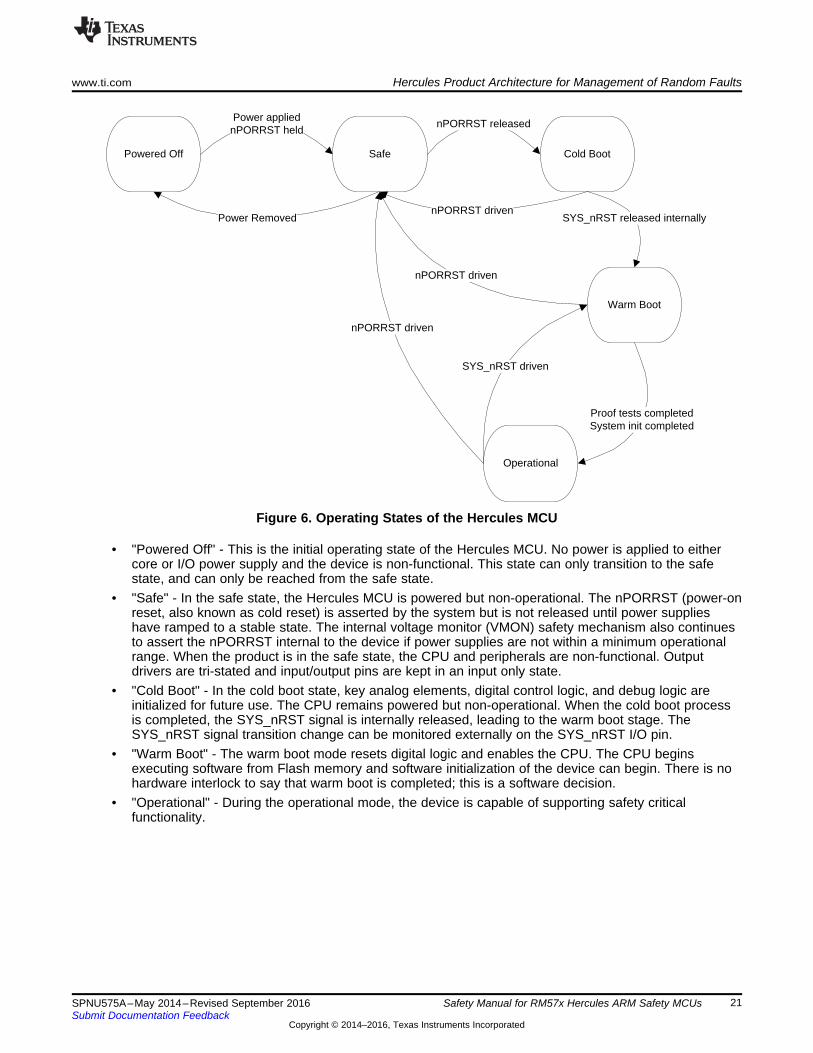
4.4 Operating StatesThe Hercules MCU products have a common architectural definition of operating states. These operatingstates should be observed by the system developer in their software and system level design concepts.The operating states state machine is shown in Figure 6 and described below.
SafePowered Off
Power appliednPORRST held
Cold Boot
nPORRST released
Warm Boot
SYS_nRST released internally
Operational
Proof tests completedSystem init completed
nPORRST driven
Power Removed
SYS_nRST driven
nPORRST driven
nPORRST driven
www.ti.com Hercules Product Architecture for Management of Random Faults
21SPNU575A–May 2014–Revised September 2016Submit Documentation Feedback
Copyright © 2014–2016, Texas Instruments Incorporated
Safety Manual for RM57x Hercules ARM Safety MCUs
Figure 6. Operating States of the Hercules MCU
• "Powered Off" - This is the initial operating state of the Hercules MCU. No power is applied to eithercore or I/O power supply and the device is non-functional. This state can only transition to the safestate, and can only be reached from the safe state.
• "Safe" - In the safe state, the Hercules MCU is powered but non-operational. The nPORRST (power-onreset, also known as cold reset) is asserted by the system but is not released until power supplieshave ramped to a stable state. The internal voltage monitor (VMON) safety mechanism also continuesto assert the nPORRST internal to the device if power supplies are not within a minimum operationalrange. When the product is in the safe state, the CPU and peripherals are non-functional. Outputdrivers are tri-stated and input/output pins are kept in an input only state.
• "Cold Boot" - In the cold boot state, key analog elements, digital control logic, and debug logic areinitialized for future use. The CPU remains powered but non-operational. When the cold boot processis completed, the SYS_nRST signal is internally released, leading to the warm boot stage. TheSYS_nRST signal transition change can be monitored externally on the SYS_nRST I/O pin.
• "Warm Boot" - The warm boot mode resets digital logic and enables the CPU. The CPU beginsexecuting software from Flash memory and software initialization of the device can begin. There is nohardware interlock to say that warm boot is completed; this is a software decision.
• "Operational" - During the operational mode, the device is capable of supporting safety criticalfunctionality.

Hercules Product Architecture for Management of Random Faults www.ti.com
22 SPNU575A–May 2014–Revised September 2016Submit Documentation Feedback
Copyright © 2014–2016, Texas Instruments Incorporated
Safety Manual for RM57x Hercules ARM Safety MCUs
4.5 Management of ErrorsWhen a diagnostic detects a fault, the error must be indicated. The Hercules product architecture providesaggregation of fault indication from internal safety mechanisms using a peripheral logic known as the errorsignaling module (ESM). The ESM provides mechanisms to classify errors by severity and to provideprogrammable error response. The ESM does not, in and of itself, impact the overall function of the deviceand serves the limited purpose of fault aggregation and classification. The error classifications in the ESMare summarized in Table 2.
Table 2. Summary of ESM Error Indication
Error Group Interrupt Response Error Pin Response Notes
1 Programmable interrupt andprogrammable interrupt priority Programmable response For errors that are generally not of critical
severity2 Non maskable interrupt generated Error pin activated For errors that are generally of critical severity
3 No interrupt response Error pin activated For critical errors that are seen by diagnosticimplemented in CPU
The error response is action that is taken by the MCU or system when an error is indicated. There aremultiple potential of error response possible for the Hercules product. The system integrator is responsibleto determine what error response should be taken and to ensure that this is consistent with the systemsafety concept.• CPU abort - This response is implemented directly in the CPU, for diagnostics implemented in the
CPU. During an abort, the program sequence transfers context to an abort handler and software hasan opportunity to manage the fault.
• CPU interrupt - This response can be implemented for diagnostics outside the CPU. An interruptallows events external to the CPU to generate a program sequence context transfer to an interrupthandler where software has an opportunity to manage the fault.
• Generation of SYS_nRST - This response allows the device to change states to warm boot fromoperational state. The SYS_nRST could be generated from an external monitor or internally by thesoftware reset or watchdog. Re-entry to the warm reset state allows possibility for software recoverywhen recovery in the operational state was not possible.
• Generation of nPORRST - This response allows the device to change state to safe state from coldboot, warm boot, or operational states. From this state, it is possible to re-enter cold boot to attemptrecovery when recovery via warm boot is not possible. It is also possible to move to the powered-downstate, if desired, to implement a system level safe state. This response can be generated from theinternal voltage monitor, but is primarily driven by monitors external to the MCU.
The ESM provides multiple registers that can be read by the CPU to determine the current status ofdiagnostics and the state of the nERROR pin. For the severe group 2 errors, a shadow register isprovided that is not reset by SYS_nRST. This allows the possibility of warm reset reinitialization to identifythat a group 2 error initiated the external reset.
It is possible for the CPU to trigger the nERROR pin response manually to test system behavior or tonotify external logic of an internal fault not automatically indicated to ESM. The CPU is responsible to clearindicated errors in the ESM, including clearing of the nERROR pin response.
The EPC is used as a complement to the ESM for error profiling . The primary goal of this module is toprovide a unified correctable ECC error (single bit ECC fault) profiling capability and error address cacheon ECC failures in system bus memory slaves like Flash, FEE, and SRAM. The secondary goal of thismodule is to provide an ECC error reporting capability for bus masters, which do not natively have ECClogic built in like the DMA and TUs. The ECC generation and evaluation logic for bus masters such asDMA and the TUs are built into the CPU Interconnect Subsystem.
System level management of the external error response can be simplified through the use of a TITPS6538x power supply and safety companion device developed for use with the Hercules family.
www.ti.com System Integrator Recommendations
23SPNU575A–May 2014–Revised September 2016Submit Documentation Feedback
Copyright © 2014–2016, Texas Instruments Incorporated
Safety Manual for RM57x Hercules ARM Safety MCUs
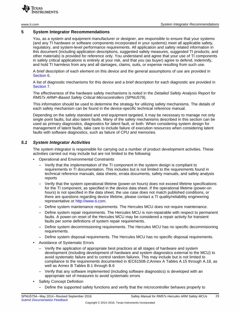
5 System Integrator RecommendationsYou, as a system and equipment manufacturer or designer, are responsible to ensure that your systems(and any TI hardware or software components incorporated in your systems) meet all applicable safety,regulatory, and system-level performance requirements. All application and safety related information inthis document (including application descriptions, suggested safety measures, suggested TI products, andother materials) is provided for reference only. You understand and agree that your use of TI componentsin safety critical applications is entirely at your risk, and that you (as buyer) agree to defend, indemnify,and hold TI harmless from any and all damages, claims, suits, or expense resulting from such use.
A brief description of each element on this device and the general assumptions of use are provided inSection 6.
A list of diagnostic mechanisms for this device and a brief description for each diagnostic are provided inSection 7.
The effectiveness of the hardware safety mechanisms is noted in the Detailed Safety Analysis Report forRM57x ARM®-Based Safety Critical Microcontrollers (SPNU579).
This information should be used to determine the strategy for utilizing safety mechanisms. The details ofeach safety mechanism can be found in the device-specific technical reference manual.
Depending on the safety standard and end equipment targeted, it may be necessary to manage not onlysingle point faults, but also latent faults. Many of the safety mechanisms described in this section can beused as primary diagnostics, diagnostics for latent fault, or both. When considering system design formanagement of latent faults, take care to include failure of execution resources when considering latentfaults with software diagnostics, such as failure of CPU and memories.
5.1 System Integrator ActivitiesThe system integrator is responsible for carrying out a number of product development activities. Theseactivities carried out may include but are not limited to the following:• Operational and Environmental Constraints
– Verify that the implementation of the TI component in the system design is compliant torequirements in TI documentation. This includes but is not limited to the requirements found intechnical reference manuals, data sheets, errata documents, safety manuals, and safety analysisreports
– Verify that the system operational lifetime (power-on hours) does not exceed lifetime specificationsfor the TI component, as specified in the device data sheet. If the operational lifetime (power-onhours) is not specified in the data sheet, the use case does not match published conditions, orthere are questions regarding device lifetime, please contact a TI quality/reliability engineeringrepresentative or http://www.ti.com.
– Define system maintenance requirements. The Hercules MCU does not require maintenance.– Define system repair requirements. The Hercules MCU is non-repairable with respect to permanent
faults. A power-on reset of the Hercules MCU may be considered a repair activity for transientfaults per some definitions of system repair requirements.
– Define system decommissioning requirements. The Hercules MCU has no specific decommisioningrequirements.
– Define system disposal requirements. The Hercules MCU has no specific disposal requirements.• Avoidance of Systematic Errors
– Verify the application of appropriate best practices at all stages of hardware and systemdevelopment (including development of hardware and system diagnostics external to the MCU) toavoid systematic failure and to control random failures. This may include but is not limited tocompliance to the requirements documented in IEC61508-2;Annex A Tables A.15 through A.18, aswell as Annex B Tables B.1 through B.6
– Verify that any software implemented (including software diagnostics) is developed with anappropriate set of measures to avoid systematic errors
• Safety Concept Definition– Define the supported safety functions and verify that the microcontroller behaves properly to

System Integrator Recommendations www.ti.com
24 SPNU575A–May 2014–Revised September 2016Submit Documentation Feedback
Copyright © 2014–2016, Texas Instruments Incorporated
Safety Manual for RM57x Hercules ARM Safety MCUs
support execution of the defined safety function. This microcontroller is a generic product, which iscapable of supporting a variety of safety functions but does not have fixed support for any specificsafety function.
– Define the system-level safe state concept considering safe-state entry, maintenance of safe state,and safe-state exit as appropriate to the application and verify correct implementation
– Define the system-level error-handling concept and verify correct implementation.– Define appropriate overall timing requirements for safety metrics to be calculated for the application– Define appropriate safety metric targets for the application
• Safety Concept Implementation– Select and implement an appropriate set of diagnostics and safety mechanisms from the MCU
safety manual as necessary to satisfy the requirements of the targeted standards and the high levelsafety concept. Dependent on the results of the system level safety analysis, it may not benecessary to implement all diagnostic measures which TI has identified.
– For the device diagnostics listed as "system" in Table 4, implement the diagnostic in a manner thatmeets functional safety requirements of the system, particularly monitoring of the external clock,monitoring of voltage, and MCU state monitoring via external watchdog logic. TI's recommendationsare based on analysis of what faults might be detected external to the MCU when considering faultmodels/failure modes described in IEC 61508 -2 Annex A as to be considered for any claims ofhigh diagnostic coverage, including both permanent and transient failure modes.
– Implement appropriate mechanisms to detect shorts between pins on the device. Tests may includeI/O loopback tests, information redundancy, or system-level mechanisms designed to detect shorts.
– Any end-to-end communications diagnostics implemented should consider the failure modes andpotential mitigating safety measures described in IEC 61784-3:2010 and summarized in IEC 61784-3:2010 in Table 1.
– Ensure that any additional system level hardware or software diagnostics created or implementedby the system integrator are developed with an appropriate process to avoid systematic errors.
– Define an appropriate diagnostic test interval per diagnostic to be implemented.• Verification of Safety Concept including Safety Metric Calculation
– Verify the behavior of the MCU outputs in the system when the MCU is in a faulted condition.– Evaluate the system design for specific failure modes of functional logic and diagnostic logic which
are detectable based on the specific application usage and the specific diagnostics applied. TI'ssafety analysis for the MCU considers all fault models noted in IEC 61508-2 Annex A as to beconsidered for any claims of high diagnostic coverage, including both permanent and transientfailure modes. Refer to the Safety Analysis Report for more details.
– Evaluate the system design for specific failure modes of functional logic and diagnostic logic whichare not detectable based on the specific application usage and the specific diagnostics applied. TI'ssafety analysis for the MCU considers all fault models noted in IEC 61508-2 Annex A as to beconsidered for any claims of high diagnostic coverage, including both permanent and transientfailure modes. Refer to the Safety Analysis Report for more details and ensure that the systemdesign considers system level diagnostics recommended by TI, such as external voltagesupervision, external watchdog, and so forth.
– Verify that the implemented diagnostics meet the target diagnostic test interval per diagnostic.– Estimate failure rates and diagnostic coverage per failure mode with respect to specific application
usage. TI provides tools to support this activity in the Safety Analysis Report (SAR).– Verify that environmental and operational constraints are properly modeled in the FMEDA to
provide failure rate estimates.– Verify that appropriate on-chip design elements are selected in the FMEDA for the specific safety
function under analysis.– Verify that targeted safety metrics are calculated and achieved– Verify the diagnostic coverage achieved by the implemented system and software based
diagnostics.– Verify that the safety analysis considers MCU elements which are necessary to support the primary
function, such as clock, power, OTP configuration, and similar. Many times the focus of analysis is

www.ti.com System Integrator Recommendations
25SPNU575A–May 2014–Revised September 2016Submit Documentation Feedback
Copyright © 2014–2016, Texas Instruments Incorporated
Safety Manual for RM57x Hercules ARM Safety MCUs
the functional datapath but the elements necessary to support proper operation should also beconsidered.
– Execute a co-existence/freedom from interference analysis per the targeted standard to confirm thatimplemented functionality can co-exist without interference.
– Execute a dependent failure/common cause analysis to consider possible dependent/commoncause failures on the sub-elements of the MCU, including pin level connections.
5.2 Hints for Performing Dependent/Common Cause Failure Analysis Including theHercules MCUThe following steps may be useful for performing dependent/common cause failure analysis when usingthe Hercules MCU:• Consider a relevant list of dependent fault/common cause fault initiators, such as the lists found in the
draft ISO/PAS 19451 document, “Application of ISO 26262 to Semiconductors”• Verify that the dependent failure analysis considers the impact of the software tasks running on the
MCU, including hardware and software interactions and task/operating system interactions.• Verify that the dependent failure analysis considers the impact of pin/ball level interactions on the MCU
package, including aspects related to the selected I/O multiplexing
5.3 Hints for Improving Independence of Function/Co-Existence of Function When Usingthe Hercules MCUThe following steps may be useful for improving independence of function when using the Hercules MCU:• Verify that unused interrupt channels are disabled in the VIM• Verify that unused interrupt sources are disabled in the source peripherals• Hold peripheral chip selects in reset with the PCR if the peripherals are unused• Leave peripherals in default reset state if not controlled via PCR• Power down power domains if all logic in power domain is not used• Disable event triggers if unused• Power down the ADC cores if MibADCs are unused• Utilize peripheral bus master memory protection units (MPUs) to only allow access to needed transmit
and receive buffers• Utilize the CPU MPU to support isolation of separate software tasks running on the CPU• Utilize privileged access modes as a secondary level of task isolation• Utilize bus master ID filtering when available to limit allocation of peripherals to bus masters• When possible, separate critical I/O functions by using non adjacent I/O pins/balls. Consider using the
pin muxing logic to support such separation.• Power down unused clock sources.• Disable unused clock domains.• Power down the flash pump logic if flash memory is not used after boot.
5.4 Support for System Integrator ActivitiesIf you have any questions regarding usage of the TI documentation for system integration, or if you havequestions regarding MCU level functional safety standard work products not provided as part of the TIdocumentation package, please contact TI support. The preferred and fastest method to contact TIsupport is via the E2E forum at http://e2e.ti.com/support/microcontrollers/hercules/default.aspx.

Brief Description of Elements www.ti.com
26 SPNU575A–May 2014–Revised September 2016Submit Documentation Feedback
Copyright © 2014–2016, Texas Instruments Incorporated
Safety Manual for RM57x Hercules ARM Safety MCUs
6 Brief Description of ElementsThis section contains a brief description of the elements identified on this device in Table 1. For a fullfunctional description of any of these modules, see the device-specific technical reference manual.
6.1 Power SupplyThe Hercules device family products require an external device to supply the necessary voltages andcurrents for proper operation. Separate voltage rails are available for core logic and I/O logic (includingmulti-buffered analog-to-digital converter (MibADC), Flash pump and oscillator).
The following tests can be applied as diagnostics for this module (to provide diagnostic coverage on aspecific function):• Internal Voltage Monitor (VMON)• External Voltage Supervisor• MibADC Converter Calibration• External Watchdog
6.1.1 Notes• Management of voltage supervision at system level can be simplified by using a TI TPS6538x power
supply and safety companion device developed for use with the Hercules family.• Devices can be implemented with multiple power rails that are intended to be ganged together on the
system PCB. For proper operation of power diagnostics, it is recommended to implement one voltagesupervisor per ganged rail.
• Common mode failure analysis of the external voltage supervisor may be useful to determinedependencies in the voltage generation and supervision circuitry
6.2 Power Management Module (PMM)The power management module (PMM) is responsible for control of switchable power domains.Dependent on the family variant used, one or more power domains can be implemented. Power domainscan be permanently configured at manufacturing time by TI or they can be user programmable. Todetermine the power domains supported on your MCU, see the device-specific data sheet. Forprogramming information, see the device-specific technical reference manual.
The following tests can be applied as diagnostics for this module (to provide diagnostic coverage on aspecific function):• Internal Voltage Monitor (VMON)• External Voltage Supervisor• Lockstep PSCON• Power Domain Inactivity Monitor• Privileged Mode Access and Multi-Bit Keys for Control Registers• Periodic Software Readback of Static Configuration Registers• Software Readback of Written Configuration
The following tests can be applied as a test-for-diagnostic on this module, and could be used to meetLatent Fault Metric Requirements of ISO26262 (in combination with other diagnostics on the primaryfunction):• PSCON Lockstep Comparator Self Test• Internal Watchdog• External Watchdog• CPU Lockstep Compare• Flash Data ECC• SRAM Data ECC

www.ti.com Brief Description of Elements
27SPNU575A–May 2014–Revised September 2016Submit Documentation Feedback
Copyright © 2014–2016, Texas Instruments Incorporated
Safety Manual for RM57x Hercules ARM Safety MCUs
6.2.1 Notes• PSCONs continue to function normally during lockstep compare self-test, but no comparison function is
present.• When the CPU is in a halting debug state, no comparison of PSCON outputs is performed.
6.3 ClocksThe Hercules device family products are primarily synchronous logic devices and as such require clocksignals for proper operation. The clock management logic includes clock sources, clock generation logicincluding clock multiplication by phase lock loops (PLLs), clock dividers, and clock distribution logic. Theregisters that are used to program the clock management logic are located in the system control module.
The following tests can be applied as diagnostics for this module (to provide diagnostic coverage on aspecific function):• LPOCLKDET• PLL Slip Detector• Dual Clock Comparator (DCC)• External Monitoring via ECLK• Internal Watchdog - DWD• Internal Watchdog - DWWD• External Watchdog• Periodic Software Readback of Static Configuration Registers• Software Readback of Written Configuration
The following tests can be applied as test-for-diagnostics on this module to meet Latent Fault MetricRequirements of ISO26262 (in combination with other diagnostics on the primary function):• Software Test of DCC Functionality• Software Test of DWD Functionality• Software Test of DWWD Functionality• CPU Lockstep Compare• Flash Data ECC• SRAM Data ECC
6.3.1 Notes• Management of the external watchdog functionality at system level can be simplified by using a TI
TPS6538x power supply and safety companion device developed for use with the Hercules family.• User can improve the accuracy of the LPOCLKDET diagnostic via programming the trim values in the
HF LPO. This would require the customer to determine the LPO trim value during their manufacturingtest via comparison to a calibrated clock source.
• There are many possible implementations of watchdogs for use in providing clock and CPUdiagnostics. In general, TI advises the use of an external watchdog over an internal watchdog forreasons of reduced common mode failure. TI also advises the use of a program sequence, windowed,or question and answer watchdog as opposed to a single threshold watchdog due to the additionalfailure modes that can be detected by a more advanced watchdog.
• Driving a high-frequency clock output on the ECLK pin may have EMI implications.
6.4 ResetThe Hercules device family products require an external reset at cold and power-on (nPORRST) to placeall asynchronous and synchronous logic into a known state. The power-on reset generates an internalwarm reset (nRST) signal to reset the majority of digital logic as part of the boot process. The nRST signalis provided at device level as an I/O pin; it will toggle when asserted internally and can be driven externallyto generate a warm reset. For more information on the reset functionality, see the device-specific datasheet.
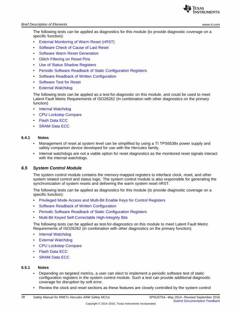
Brief Description of Elements www.ti.com
28 SPNU575A–May 2014–Revised September 2016Submit Documentation Feedback
Copyright © 2014–2016, Texas Instruments Incorporated
Safety Manual for RM57x Hercules ARM Safety MCUs
The following tests can be applied as diagnostics for this module (to provide diagnostic coverage on aspecific function):• External Monitoring of Warm Reset (nRST)• Software Check of Cause of Last Reset• Software Warm Reset Generation• Glitch Filtering on Reset Pins• Use of Status Shadow Registers• Periodic Software Readback of Static Configuration Registers• Software Readback of Written Configuration• Software Test for Reset• External Watchdog
The following tests can be applied as a test-for-diagnostic on this module, and could be used to meetLatent Fault Metric Requirements of ISO26262 (In combination with other diagnostics on the primaryfunction)• Internal Watchdog• CPU Lockstep Compare• Flash Data ECC• SRAM Data ECC
6.4.1 Notes• Management of reset at system level can be simplified by using a TI TPS6538x power supply and
safety companion device developed for use with the Hercules family.• Internal watchdogs are not a viable option for reset diagnostics as the monitored reset signals interact
with the internal watchdogs.
6.5 System Control ModuleThe system control module contains the memory-mapped registers to interface clock, reset, and othersystem related control and status logic. The system control module is also responsible for generating thesynchronization of system resets and delivering the warm system reset nRST.
The following tests can be applied as diagnostics for this module (to provide diagnostic coverage on aspecific function):• Privileged Mode Access and Multi-Bit Enable Keys for Control Registers• Software Readback of Written Configuration• Periodic Software Readback of Static Configuration Registers• Multi-Bit Keyed Self-Correctable High-Integrity Bits
The following tests can be applied as test-for-diagnostics on this module to meet Latent Fault MetricRequirements of ISO26262 (in combination with other diagnostics on the primary function):• Internal Watchdog• External Watchdog• CPU Lockstep Compare• Flash Data ECC• SRAM Data ECC
6.5.1 Notes• Depending on targeted metrics, a user can elect to implement a periodic software test of static
configuration registers in the system control module. Such a test can provide additional diagnosticcoverage for disruption by soft error.
• Review the clock and reset sections as these features are closely controlled by the system control

www.ti.com Brief Description of Elements
29SPNU575A–May 2014–Revised September 2016Submit Documentation Feedback
Copyright © 2014–2016, Texas Instruments Incorporated
Safety Manual for RM57x Hercules ARM Safety MCUs
module.
6.6 Error Signaling Module (ESM)The ESM provides unified aggregation and prioritization of on-board hardware diagnostic errors. For moreinformation, see Management of Errors.
The following tests can be applied as diagnostics for this module (to provide diagnostic coverage on aspecific function):• Periodic Software Readback of Static Configuration Registers• Boot Time Software Test of Error Path Reporting• Periodic Software Test of Error Path Reporting• Use of Status Shadow Registers• Software Readback of Written Configuration
The following tests can be applied as test-for-diagnostics on this module to meet Latent Fault MetricRequirements of ISO26262 (in combination with other diagnostics on the primary function):• Internal Watchdog• External Watchdog• CPU Lockstep Compare• Flash Data ECC• SRAM Data ECC
6.6.1 Notes• Software testing of the ESM error path can be combined with boot time latent tests of hardware
diagnostics to reduce startup time.• Testing of ESM error path may result in assertion of the nERROR diagnostic output. System integrator
should ensure that the system can manage or recover gracefully from the nERROR event.
6.7 CPU SubsystemThe Hercules product family relies on the ARM® Cortex-R5F CPU to provide general-purpose processing.The Cortex-R5F is a high performance CPU with embedded safety diagnostics. The R5F is also designedfor easy integration into a 1oo1D lockstep configuration. These aspects make the Cortex-R5F anoutstanding CPU for functional safety products.
The following tests can be applied as diagnostics for this module (to provide diagnostic coverage on aspecific function):• CPU Lockstep Compare• Boot Time Execution of LBIST STC• Periodic Execution of LBIST STC• Memory Protection Unit (MPU)• Online Profiling Using PMU• Illegal Operation and Instruction Trapping• Periodic Software Readback of Static Configuration Registers• Software Read Back of CPU Registers• Boot Time PBIST Check of CPU cache Memories• Periodic Time PBIST Check of CPU cache Memories• ECC on Cache Memories• Hardware Disable of JTAG Port• Internal Watchdog• External Watchdog

CPU Bus Compare
PD Inactivity
Monitor
VIM Bus Compare
Checker CPU
Inactivity Monitor
CPU1
(Main CPU)
CPU2
(Checker
CPU)
2 cycle delay
VIM1 VIM2
2 cycle delay
Inputs to CPU1
cpu2clk
cpu1clkOutputs from CPU1 to
the system
Outputs from CPU2 to
the system
Safe values (values
that will force the
�Z��l����Wh[��}µ��µ���
to inactive states)
CCM-R5F
Compare errorsESM
PDx PDy
Brief Description of Elements www.ti.com
30 SPNU575A–May 2014–Revised September 2016Submit Documentation Feedback
Copyright © 2014–2016, Texas Instruments Incorporated
Safety Manual for RM57x Hercules ARM Safety MCUs
The following tests can be applied as a test-for-diagnostic on this module, and could be used to meetLatent Fault Metric Requirements of ISO26262 (in combination with other diagnostics on the primaryfunction):• Lockstep Compare Self-Test• LBIST Auto-Coverage• Software Test of PBIST• PBIST Auto-Coverage• Software Readback of Written Configuration (PBIST)• Flash Data ECC• Data ECC
6.7.1 Measures to Mitigate Common Mode Failure in CPU SubsystemThe Hercules lockstep CPU subsystem design includes multiple best practices to mitigate common modefailure:• Physical diversity:
– Physical core hard macros are spaced at least 100 µm apart.– Each CPU is uniquely diversified in terms of the cell placements .
• Temporal diversity:– Timing delay blocks are inserted to delay the operation of the CPUs by two cycles as shown in
Figure 7.
Figure 7. Lockstep Temporal Diversity

www.ti.com Brief Description of Elements
31SPNU575A–May 2014–Revised September 2016Submit Documentation Feedback
Copyright © 2014–2016, Texas Instruments Incorporated
Safety Manual for RM57x Hercules ARM Safety MCUs
– The CPU clock domain is split into two clock trees such that clocks are delivered to the two CPUsby separate paths.
• Power diversity:– Each core has a dedicated 40 µm power ring.
6.7.2 Notes• Many safety critical microcontrollers utilize a software-based test of CPU functionality as opposed to a
hardware scheme such as the TI LBIST STC. TI does not recommend such tests for a CPU of mediumto high complexity, such as the Cortex-R5F. Software-based options have higher memory cost, lowerdetection capability, and longer execution times than the equivalent LBIST STC solution.
• Due to the lockstep diagnostic, it is not necessary to execute a periodic test of CPU control registerconfiguration. A control register disturb in one CPU should not impact the second CPU.
• Cache controller logic is included in the lockstep CPU and as such is checked on a cycle by cyclebasis.
6.8 Primary Embedded FlashThe primary embedded flash memory is a non-volatile memory residing on the CPU InterconnectSubsystem. The primary flash memory is mainly used for CPU instruction access, though data access isalso possible. Access to the Flash memory can take multiple CPU cycles. A flash wrapper logic providesmultiple pipelined read buffers to improve CPU access time on sequential address fetches.
The following tests can be applied as diagnostics for this module (to provide diagnostic coverage on aspecific function):• Flash Data ECC• Hard Error Cache and Livelock• Flash Wrapper Address ECC• Address and Control Parity• Boot Time Check of Flash Memory Contents by Hardware CRC• Periodic Check of Flash Memory Contents by Hardware CRC• Bit Multiplexing in Flash Memory Array• Flash Sector Protection• Periodic Software Readback of Static Configuration Registers• Software Readback of Written Configuration
The following tests can be applied as a test-for-diagnostic on this module, and could be used to meetLatent Fault Metric Requirements of ISO26262 (in combination with other diagnostics on the primaryfunction):• Flash Wrapper Diag Mode 5 Test• Flash Wrapper Diag Mode 7 Test• Software Test of Parity Logic• Software Test of Flash Sector Protection Logic• Software Test of Hardware CRC• CRC Auto-Coverage• Internal Watchdog• External Watchdog• CPU Lockstep Compare• SRAM Data ECC• CPU Interconnect Hardware Checker• Timeout Monitoring on Bus Transactions

Brief Description of Elements www.ti.com
32 SPNU575A–May 2014–Revised September 2016Submit Documentation Feedback
Copyright © 2014–2016, Texas Instruments Incorporated
Safety Manual for RM57x Hercules ARM Safety MCUs
6.8.1 Notes• When exporting ECC error events from the Flash wrapper to ESM, care should be taken that the error
is not due to discarded prefetch or other branch discontinuity.• By executing a CRC read back of Flash contents while ECC is enabled on the Flash, it is possible to
perform two diagnostics of the Flash in parallel.• The Flash module may have unique power supply pins depending on the product configuration.
Implementation of external voltage supervision on these pins can be considered to improve systemsafety integrity measures as described in the power supply section.
• The Flash module may have unique test signal pins depending on the product configuration. Forproper board level management of these signals, see the device-specific data sheet.
• To take advantage of error profiling features and to propagate error events from bus masters, the EPCmodule must be initialized.
6.9 Flash EEPROM Emulation (FEE)The Hercules platform architecture includes the capability for a separate bank of Flash memory to be usedas Flash EEPROM Emulation (FEE). FEE is used for data storage only, and cannot be used as a CPUinstruction memory. FEE is a level two memory that is accessed by the CPU over the AXI master port.The emulation of EEPROM in the FEE memory is managed by specific FEE drivers running on the CPU.
The following tests can be applied as diagnostics for this module (to provide diagnostic coverage on aspecific function):• FEE Data ECC• Boot Time Check of FEE Memory Contents by Hardware CRC• Periodic Check of FEE Memory Contents by Hardware CRC• Bit Multiplexing in FEE Array• FEE Sector Protection• Periodic Software Readback of Static Configuration Registers• Software Readback of Written Configuration• Flash Wrapper Address ECC
The following tests can be applied as a test-for-diagnostic on this module, and could be used to meetLatent Fault Metric Requirements of ISO26262 (in combination with other diagnostics on the primaryfunction):• Flash Wrapper Diag Mode 5 Test• Flash Wrapper Diag Mode 7 Test• Software Test of Flash Sector Protection Logic• Software Test of Hardware CRC• CRC Auto-Coverage• Internal Watchdog• External Watchdog• CPU Lockstep Compare• Flash Data ECC• SRAM Data ECC• CPU Interconnect Hardware Checker• Timeout Monitoring on Bus Transactions

www.ti.com Brief Description of Elements
33SPNU575A–May 2014–Revised September 2016Submit Documentation Feedback
Copyright © 2014–2016, Texas Instruments Incorporated
Safety Manual for RM57x Hercules ARM Safety MCUs
6.9.1 Notes• As all application FEE accesses are run through a software driver to manage EEPROM emulation, any
diagnostics must respect the functionality of the FEE driver.• The FEE module may have unique power supply pins depending on the product configuration.
Implementation of external voltage supervision on these pins can be considered to improve systemsafety integrity measures as described in the power supply section.
• The FEE module may have unique test signal pins depending on the product configuration. For properboard level management of these signals, see the device-specific data sheet.
• To take advantage of error profiling features and to propagate error events from bus masters, the EPCmodule must be initialized.
6.10 Primary Embedded SRAMThe primary embedded SRAM is a volatile memory that is accessed via the level two CPU InterconnectSubsystem. The SRAMs are primarily used for CPU data access, though instruction access is alsopossible as is access via other bus masters.
The following tests can be applied as diagnostics for this module (to provide diagnostic coverage on aspecific function):• Data ECC• Hard Error Cache and Livelock• Correctable ECC Profiling• Address and Control Bus Parity• Redundant Address Decode• Data and ECC Storage in Multiple Physical Banks• Boot Time PBIST Check of Primary SRAM• Periodic PBIST Check of Primary SRAM• Bit Multiplexing in Primary SRAM Array• Periodic Hardware CRC Check of Primary SRAM Contents• Periodic Software Readback of Static Configuration Registers• Software Readback of Written Configuration• Scrubbing of SRAM to Correct Detected Single Bit Errors
The following tests can be applied as a test-for-diagnostic on this module, and could be used to meetLatent Fault Metric Requirements of ISO26262 (in combination with other diagnostics on the primaryfunction):• Software Test of SRAM Wrapper Redundant Address Decode and ECC• Software Test of Parity Logic• Software Test of PBIST• PBIST Auto-Coverage• Software Test of ECC Profiler• Redundant Address Decode Self Test• Software Test of Hardware CRC• CRC Auto-Coverage• Internal Watchdog• External Watchdog• CPU Lockstep Compare• Flash Data ECC

Brief Description of Elements www.ti.com
34 SPNU575A–May 2014–Revised September 2016Submit Documentation Feedback
Copyright © 2014–2016, Texas Instruments Incorporated
Safety Manual for RM57x Hercules ARM Safety MCUs
6.10.1 Notes• By executing a CRC read back of SRAM contents while ECC is enabled on the SRAM, it is possible to
perform two diagnostics of the SRAM in parallel.• The SRAM module may have unique power supply pins depending on the product configuration.
Implementation of external voltage supervision on these pins can be considered to improve systemsafety integrity measures as described in the power supply section.
• The redundant address decode does not provide hardware fault tolerance. As such, the logic may notbe considered fully redundant per the definition of redundancy in some safety standards.
• To take advantage of error profiling features and to propagate error events from bus masters, the EPCmodule must be initialized.
6.11 CPU Interconnect SubsystemThe CPU Interconnect Subsystem is composed of a number of bridges, gaskets, communicationscrossbars, and routing logic, which connects the bus masters (DMA, CPU, TUs, and so forth) to L2memory slaves.
The following tests can be applied as diagnostics for this module (to provide diagnostic coverage on aspecific function):• Error Trapping (Including Peripheral Slave Error Trapping)• Information Redundancy• Periodic Software Readback of Static Configuration Registers• Boot Time Software Test of Basic Functionality Including Error Tests• Periodic Software Test of Basic Functionality Including Error Tests• Software Readback of Written Configuration• Transmission Redundancy• Execution of Interconnect Self-Test• CPU Interconnect Hardware Checker• Timeout Monitoring on Bus Transactions• Transaction ECC (Date Lines)• Transaction Parity (Address and Control Lines)• Internal Watchdog• External Watchdog
The following tests can be applied as a test-for-diagnostic on this module, and could be used to meetLatent Fault Metric Requirements of ISO26262 (in combination with other diagnostics on the primaryfunction):• CPU Lockstep Compare• Flash Data ECC• SRAM Data ECC
6.11.1 Notes• An end to end communications safety mechanism implemented on a networked peripheral provides an
indirect form of information redundancy diagnostic on the L2 and L3 interconnects.• The only module in the L2 and L3 interconnect subsystem that has memory-mapped registers is the
PCR.

www.ti.com Brief Description of Elements
35SPNU575A–May 2014–Revised September 2016Submit Documentation Feedback
Copyright © 2014–2016, Texas Instruments Incorporated
Safety Manual for RM57x Hercules ARM Safety MCUs
6.12 Peripheral Interconnect SubsystemThe Peripheral Interconnect Subsystem is composed of a number of bridges, gaskets, communicationscrossbars, and routing logic, which connects the bus masters (DMA, CPU, TUs, and so forth) to deviceperipherals. This logic, while having no explicit safety critical purpose, is an intermediary in the transfer ofsafety critical communications. The peripherals are further distributed among the three peripheralsegments that are mentioned below.
The following tests can be applied as diagnostics for this module (to provide diagnostic coverage on aspecific function):• Error Trapping (Including Peripheral Slave Error Trapping)• Peripheral Interconnect New Memory Protection Unit (NMPU)• Information Redundancy• Periodic Software Readback of Static Configuration Registers• Boot Time Software Test of Basic Functionality Including Error Tests• Periodic Software Test of Basic Functionality Including Error Tests• Software Readback of Written Configuration• Transmission Redundancy• Internal Watchdog• External Watchdog
The following tests can be applied as a test-for-diagnostic on this module, and could be used to meetLatent Fault Metric Requirements of ISO26262 (in combination with other diagnostics on the primaryfunction):• CPU Lockstep Compare• Flash Data ECC• SRAM Data ECC
6.13 Peripheral Central Resource 1 (PCR1)The Peripheral Central Resource 1 refers to the interconnect that connects the bus masters (CPU , DMAand so forth) to selected system peripherals, debug, test, emulation and instrumentation logic on the firstsegment located beneath the Peripheral Interconnect Subsystem.
The following tests can be applied as diagnostics for this module (to provide diagnostic coverage on aspecific function):• Error Trapping (Including Peripheral Slave Error Trapping)• PCR Access Management: Protection Mode and MasterID Filtering• Information Redundancy• Periodic Software Readback of Static Configuration Registers• Boot Time Software Test of Basic Functionality Including Error Tests• Periodic Software Test of Basic Functionality Including Error Tests• Software Readback of Written Configuration• Transmission Redundancy• Internal Watchdog• External Watchdog
The following tests can be applied as a test-for-diagnostic on this module, and could be used to meetLatent Fault Metric Requirements of ISO26262 (in combination with other diagnostics on the primaryfunction):• CPU Lockstep Compare• Flash Data ECC• SRAM Data ECC

Brief Description of Elements www.ti.com
36 SPNU575A–May 2014–Revised September 2016Submit Documentation Feedback
Copyright © 2014–2016, Texas Instruments Incorporated
Safety Manual for RM57x Hercules ARM Safety MCUs
6.14 Peripheral Central Resource 2 (PCR2)The Peripheral Central Resource 2 refers to the interconnect that connects the bus masters (CPU , DMAand so forth) to selected high speed and motor control peripherals on the second segment locatedbeneath the Peripheral Interconnect Subsystem.
The following tests can be applied as diagnostics for this module (to provide diagnostic coverage on aspecific function):• Error Trapping (Including Peripheral Slave Error Trapping)• PCR Access Management: Protection Mode and MasterID Filtering• Information Redundancy• Periodic Software Readback of Static Configuration Registers• Boot Time Software Test of Basic Functionality Including Error Tests• Periodic Software Test of Basic Functionality Including Error Tests• Software Readback of Written Configuration• Transmission Redundancy• Internal Watchdog• External Watchdog
The following tests can be applied as a test-for-diagnostic on this module, and could be used to meetLatent Fault Metric Requirements of ISO26262 (in combination with other diagnostics on the primaryfunction):• CPU Lockstep Compare• Flash Data ECC• SRAM Data ECC
6.15 Peripheral Central Resource 3 (PCR3)The Peripheral Central Resource 3 refers to the interconnect that connects the bus masters (DMA, CPU,and so forth) to user peripherals on the third segment located beneath the Peripheral InterconnectSubsystem.
The following tests can be applied as diagnostics for this module (to provide diagnostic coverage on aspecific function):• Error Trapping (Including Peripheral Slave Error Trapping)• PCR Access Management: Protection Mode and MasterID Filtering• Information Redundancy• Periodic Software Readback of Static Configuration Registers• Boot Time Software Test of Basic Functionality Including Error Tests• Periodic Software Test of Basic Functionality Including Error Tests• Software Readback of Written Configuration• Transmission Redundancy• Internal Watchdog• External Watchdog
The following tests can be applied as a test-for-diagnostic on this module, and could be used to meetLatent Fault Metric Requirements of ISO26262 (in combination with other diagnostics on the primaryfunction):• CPU Lockstep Compare• Flash Data ECC• SRAM Data ECC

www.ti.com Brief Description of Elements
37SPNU575A–May 2014–Revised September 2016Submit Documentation Feedback
Copyright © 2014–2016, Texas Instruments Incorporated
Safety Manual for RM57x Hercules ARM Safety MCUs
6.16 EFuse Static ConfigurationThe Hercules platform devices support a manufacturing time configuration of certain functionality (such astrim values for analog macros) via one time programmable (OTP) EFuse structures. The EFuses are readautomatically after power-on reset by an autoload function.
The following tests can be applied as diagnostics for this module (to provide diagnostic coverage on aspecific function):• Autoload Self Test• E-Fuse ECC• Periodic Software Readback of Static Configuration Registers• Software Readback of Written Configuration
The following tests can be applied as a test-for-diagnostic on this module, and could be used to meetLatent Fault Metric Requirements of ISO26262 (in combination with other diagnostics on the primaryfunction):• Autoload Self Test Auto-Coverage• EFuse ECC Logic Self Test• Internal Watchdog• External Watchdog• CPU Lockstep Compare• Flash Data ECC• SRAM Data ECC
6.17 OTP Static ConfigurationThe Hercules platform devices support a manufacturing time configuration of certain functionality (such asendianness and the initial configuration of power domains after reset) via one time programmable Flashmemory. The OTP configuration values are read automatically after warm reset by an autoload function.
The following tests can be applied as diagnostics for this module (to provide diagnostic coverage on aspecific function):• Autoload Self Test• OTP ECC• Periodic Software Readback of Static Configuration Registers• Software Readback of Written Configuration• Boot Time Hardware CRC Check of OTP Contents• Periodic Hardware CRC Check of OTP Contents• Bit Multiplexing in Flash Memory Array• Flash Sector Protection
The following tests can be applied as a test-for-diagnostic on this module, and could be used to meetLatent Fault Metric Requirements of ISO26262 (in combination with other diagnostics on the primaryfunction):• Software Test of Flash Sector Protection Logic• Software Test of Hardware CRC• CRC Auto-Coverage• Flash Wrapper Diag Mode 5 Test• Flash Wrapper Diag Mode 7 Test• Internal Watchdog• External Watchdog• CPU Lockstep Compare• Flash Data ECC

Brief Description of Elements www.ti.com
38 SPNU575A–May 2014–Revised September 2016Submit Documentation Feedback
Copyright © 2014–2016, Texas Instruments Incorporated
Safety Manual for RM57x Hercules ARM Safety MCUs
• SRAM Data ECC
6.17.1 NotesThe OTP Flash memory used for storage of the configuration words can be read by the CPU.
6.18 I/O Multiplexing Module (IOMM)The I/O multiplexing module (IOMM) provides software configurable mapping of internal module I/Ofunctionality to device pins.
The following tests can be applied as diagnostics for this module (to provide diagnostic coverage on aspecific function):• Locking Mechanism For Control Registers• Master ID Filtering• Error Trapping• Periodic Software Readback of Static Configuration Registers• Boot Time Software Test of Function Using I/O Loopback Including Error Tests• Periodic Software Test of Function Using I/O Loopback Including Error Tests• Software Readback of Written Configuration
The following tests can be applied as a test-for-diagnostic on this module, and could be used to meetLatent Fault Metric Requirements of ISO26262 (in combination with other diagnostics on the primaryfunction):• Internal Watchdog• External Watchdog• CPU Lockstep Compare• Flash Data ECC• SRAM Data ECC
6.18.1 NotesSoftware testing of the IOMM can be combined with peripheral loopback testing.
6.19 Vectored Interrupt Module (VIM)The vectored interrupt module (VIM) is used to interface peripheral interrupts to the Cortex-R5F CPU. TheVIM provides programmable interrupt prioritization, masking, and sleep mode wake up functionality. TheVIM includes a local SRAM that is used to hold the address of the interrupt handler per channel. TwoVIMs (VIM1 and VIM2) are implemented on this device. For safety diagnostics purposes the VIMs (VIM1and VIM2) are implemented and run in lock step pairs .
The following tests can be applied as diagnostics for this module (to provide diagnostic coverage on aspecific function):• VIM SRAM Data ECC• Boot Time PBIST Check of VIM SRAM• Periodic PBIST Check of VIM SRAM• Bit Multiplexing in VIM SRAM Array• Periodic Hardware CRC Check of VIM SRAM Contents• Boot Time Software Test of VIM Functionality Including Error Tests• Periodic Software Test of VIM Functionality Including Error Tests• Periodic Software Readback of Static Configuration Registers• Software Readback of Written Configuration• VIM Lockstep Compare

www.ti.com Brief Description of Elements
39SPNU575A–May 2014–Revised September 2016Submit Documentation Feedback
Copyright © 2014–2016, Texas Instruments Incorporated
Safety Manual for RM57x Hercules ARM Safety MCUs
• Internal Watchdog• External Watchdog• CPU Memory Protection Unit (MPU)• Online Profiling Using PMU
The following tests can be applied as a test-for-diagnostic on this module, and could be used to meetLatent Fault Metric Requirements of ISO26262 (in combination with other diagnostics on the primaryfunction):• Software test of ECC Logic• PBIST Test of ECC Bit Memory• Software Test of Hardware CRC• CRC Auto-Coverage• Software Test of PBIST• PBIST Auto-Coverage• CPU Lockstep Compare• Flash Data ECC• SRAM Data ECC• Lockstep Compare Self-Test
6.19.1 NotesCare should be taken to optimize any VIM software diagnostics for the mode of operation - legacy IRQand FIQ, legacy vectored, or fully hardware vectored.
6.20 Real Time Interrupt (RTI)The real time interrupt (RTI) module provides the operating system timer for the device. The OS timerfunction is used to generate internal event triggers or interrupts as needed to provide periodic operation ofsafety critical functions.
The following tests can be applied as diagnostics for this module (to provide diagnostic coverage on aspecific function):• 1oo2 Software Voting Using Secondary Free Running Counter• Periodic Software Readback of Static Configuration Registers• Software Readback of Written Configuration
The following tests can be applied as a test-for-diagnostic on this module, and could be used to meetLatent Fault Metric Requirements of ISO26262 (in combination with other diagnostics on the primaryfunction):• External Watchdog• CPU Lockstep Compare• Flash Data ECC• SRAM Data ECC
6.20.1 NotesWhen using one counter to the operating system time base counter, a diverse configuration of clocksource, scaling factor, and so forth can be used to reduce probability of common mode failure.

Brief Description of Elements www.ti.com
40 SPNU575A–May 2014–Revised September 2016Submit Documentation Feedback
Copyright © 2014–2016, Texas Instruments Incorporated
Safety Manual for RM57x Hercules ARM Safety MCUs
6.21 Direct Memory Access (DMA)The direct memory access (DMA) module is used to move data from one location to another inside thesystem. This is typically used for peripheral configuration (Flash and SRAM to peripheral transfer) andperipheral data update (peripheral buffer memory transfer to CPU SRAM for processing). The DMA istypically used by the operating system to offload bus transactions from the CPU in order to improve overallsystem performance. The DMA has a local SRAM that is used for channel control information.
The following tests can be applied as diagnostics for this module (to provide diagnostic coverage on aspecific function):• Memory Protection Unit for Bus Master Accesses• Non-Privileged Bus Master Access• Information Redundancy Techniques• DMA SRAM Data ECC• Boot Time PBIST Check of DMA SRAM• Periodic PBIST Check of DMA SRAM• Bit Multiplexing in DMA SRAM Array• Periodic Hardware CRC Check of DMA SRAM Contents• Periodic Software Readback of Static Configuration Registers• Boot Time Software Test of Basic Functinality Including Error Tests• Periodic Software Test of Basic Functinality Including Error Tests• Software Readback of Written Configuration• Transmission Redundancy• Peripheral Interconnect New Memory Protection Unit (NMPU)• Hardware Disable of JTAG Port
The following tests can be applied as a test-for-diagnostic on this module, and could be used to meetLatent Fault Metric Requirements of ISO26262 (in combination with other diagnostics on the primaryfunction):• Software test of ECC Logic• PBIST Test of ECC Bit Memory• Software Test of Hardware CRC• CRC Auto-Coverage• Software Test of PBIST• PBIST Auto-Coverage• Software Test of MPU Functionality• Multi-Bit Keyed Self-Correctable High-Integrity Bits• Internal Watchdog• External Watchdog• CPU Lockstep Compare• Flash Data ECC• SRAM Data ECC
6.22 High-End Timer (N2HET), HET Transfer Unit (HTU)The N2HET module is a programmable timer with input/output capabilities. The N2HET is implemented asa simple RISC processor with instruction set dedicated for timing operations. Complex inputs can becaptured and pre-processed by the N2HET for later processing by the CPU. Output generation is typicallypulse width modulation (PWM), but may also be simple general-purpose input/output (GIO) type signals.
Each N2HET has a dedicated micro DMA controller called HTU. The HTU provides a high bandwidthconnection for data transfer to and from N2HET from and to CPU memories.

www.ti.com Brief Description of Elements
41SPNU575A–May 2014–Revised September 2016Submit Documentation Feedback
Copyright © 2014–2016, Texas Instruments Incorporated
Safety Manual for RM57x Hercules ARM Safety MCUs
The following tests can be applied as diagnostics for this module (to provide diagnostic coverage on aspecific function):• Memory Protection Unit for HTU Bus Master Accesses• Information Redundancy Techniques• Use of DCC as Program Sequence Watchdog• Monitoring by Second N2HET• Boot Time Software Test of Function Using I/O Loopback• Periodic Software Test of Function Using I/O Loopback• N2HET/HTU SRAM Data Parity• Boot Time PBIST Check of N2HET/HTU SRAM• Periodic PBIST Check of N2HET/HTU SRAM• Bit Multiplexing in N2HET/HTU SRAM Array• Periodic Hardware CRC Check of N2HET/HTU SRAM Contents• Periodic Software Readback of Static Configuration Registers• Software Readback of Written Configuration• Transmission Redundancy for Transfer Unit• Boot Time Software test of Function Using I/O Checking In GIO Mode• Periodic Software test of Function Using I/O Checking In GIO Mode• Information Redundancy Techniques (while in GIO Mode)• Hardware Disable of JTAG Port
The following tests can be applied as a test-for-diagnostic on this module, and could be used to meetLatent Fault Metric Requirements of ISO26262 (in combination with other diagnostics on the primaryfunction):• Software test of Parity Logic• PBIST Test of Parity Bit Memory• Software Test of Hardware CRC• CRC Auto-Coverage• Software Test of PBIST• PBIST Auto-Coverage• Software Test of MPU Functionality• Software Test of DCC Functionality• Boot Time Execution of LBIST STC• Periodic Execution of LBIST STC• Internal Watchdog• External Watchdog• CPU Lockstep Compare• Flash Data ECC• SRAM Data ECC• LBIST Auto-Coverage
6.22.1 Notes• Information redundancy techniques used on N2HET can be extended to also cover the HTU bus
master operation.• To reduce probability of common mode failure, user should consider implementing multiple channels
(information redundancy) using non adjacent pins.

Brief Description of Elements www.ti.com
42 SPNU575A–May 2014–Revised September 2016Submit Documentation Feedback
Copyright © 2014–2016, Texas Instruments Incorporated
Safety Manual for RM57x Hercules ARM Safety MCUs
6.23 Multi-Buffered Analog-to-Digital Converter (MibADC)The MibADC module is used to convert analog inputs into digital values. Results are stored in internalSRAM buffers for later transfer by DMA or CPU. The Hercules device family products implement twomodules with shared channels used for fast conversion (ping-pong method). Systems implementing twochannels using the dual ADC converters may be able to claim fault tolerance in application.
The following tests can be applied as diagnostics for this module (to provide diagnostic coverage on aspecific function):• Hardware Disable of JTAG Port• Boot Time Input Self Test• Boot Time MibADC Calibration• Periodic MibADC Calibration• MibADC Information Redundancy Techniques• MibADC SRAM Data Parity• Boot Time PBIST Check of MibADC SRAM• Periodic PBIST Check of MibADC SRAM• Bit Multiplexing in MibADC SRAM Array• Periodic Hardware CRC Check of MibADC SRAM Contents• Periodic Software Readback of Static Configuration Registers• Software Readback of Written Configuration• Boot Time Software Test of Function Using I/O Checking In GIO Mode• Periodic Software Test of Function Using I/O Checking In GIO Mode• Information Redundancy Techniques (while in GIO Mode)
The following tests can be applied as a test-for-diagnostic on this module, and could be used to meetLatent Fault Metric Requirements of ISO26262 (in combination with other diagnostics on the primaryfunction):• Software test of Parity Logic• PBIST Test of Parity Bit Memory• Software Test of Hardware CRC• CRC Auto-Coverage• Software Test of PBIST• PBIST Auto-Coverage• Internal Watchdog• External Watchdog• CPU Lockstep Compare• Flash Data ECC• SRAM Data ECC
6.23.1 Notes• The MibADC module may be referred to as MibADC (Multi Buffered ADC) in some documents.• ADC module voltages should be supervised as noted in Power Supply• To reduce probability of common mode failure, user should consider implementing multiple channels
(information redundancy) using non adjacent pins.
6.24 Enhanced Pulse Width Modulators (ePWM)The enhanced pulse width modulator (ePWM) peripheral is a key element in controlling many of the powerelectronic systems found in both commercial and industrial equipments. The features supported by theePWM make it especially suitable for digital motor control.

www.ti.com Brief Description of Elements
43SPNU575A–May 2014–Revised September 2016Submit Documentation Feedback
Copyright © 2014–2016, Texas Instruments Incorporated
Safety Manual for RM57x Hercules ARM Safety MCUs
The following tests can be applied as diagnostics for this module (to provide diagnostic coverage on aspecific function):• Boot Time Software Test of Function Including Error Tests• Periodic Software Test of Function Including Error Tests• Information Redundancy Techniques• Monitoring by eCAP or N2HET• Periodic Software Readback of Static Configuration Registers• Software Readback of Written Configuration
The following tests can be applied as a test-for-diagnostic on this module, and could be used to meetLatent Fault Metric Requirements of ISO26262 (in combination with other diagnostics on the primaryfunction):• Internal Watchdog• External Watchdog• CPU Lockstep Compare• Flash Data ECC• SRAM Data ECC• Boot Time Software Test of eCAP Function• Periodic Software Test of eCAP Function• Boot Time Test of N2HET Function Including I/O Loopback• Periodic Test of N2HET Function Including I/O Loopback
6.25 Enhanced Capture (eCAP)The enhanced Capture (eCAP) module provides input capture functionality for systems where accuratetiming of external events is important.
The following tests can be applied as diagnostics for this module (to provide diagnostic coverage on aspecific function):• Boot Time Software Test of Function Including Error Tests• Periodic Software Test of Function Including Error Tests• Information Redundancy Techniques• Periodic Software Readback of Static Configuration Registers• Software Readback of Written Configuration
Information Redundancy Techniques (while in PWM Mode)• Monitoring by eCAP or N2HET (while in PWM Mode)
The following tests can be applied as a test-for-diagnostic on this module, and could be used to meetLatent Fault Metric Requirements of ISO26262 (in combination with other diagnostics on the primaryfunction):• Internal Watchdog• External Watchdog• CPU Lockstep Compare• Flash Data ECC• SRAM Data ECC
6.25.1 Notes• If using the eCAP in PWM output mode, see the guidance for the Section 6.24.• N2HET channels can be used for input capture as a hardware diverse second channel to implement
information redundancy with reduced probability of common mode failure.

Brief Description of Elements www.ti.com
44 SPNU575A–May 2014–Revised September 2016Submit Documentation Feedback
Copyright © 2014–2016, Texas Instruments Incorporated
Safety Manual for RM57x Hercules ARM Safety MCUs
6.26 Enhanced Quadrature Encoder Pulse (eQEP)The enhanced quadrature encoder pulse (eQEP) module is used for direct interface with a linear or rotaryincremental encoder to get position, direction, and speed information from a rotating machine for use in ahigh-performance motion and position-control system.
The following tests can be applied as diagnostics for this module (to provide diagnostic coverage on aspecific function):• Boot Time Software Test of Function Including Error Tests• Periodic Software Test of Function Including Error Tests• Information Redundancy Techniques• Periodic Software Readback of Static Configuration Registers• Software Readback of Written Configuration• Quadrature Watchdog

www.ti.com Brief Description of Elements
45SPNU575A–May 2014–Revised September 2016Submit Documentation Feedback
Copyright © 2014–2016, Texas Instruments Incorporated
Safety Manual for RM57x Hercules ARM Safety MCUs
The following tests can be applied as a test-for-diagnostic on this module, and could be used to meetLatent Fault Metric Requirements of ISO26262 (in combination with other diagnostics on the primaryfunction):• Software Test of Quadrature Watchdog Functionality• Internal Watchdog• External Watchdog• CPU Lockstep Compare• Flash Data ECC• SRAM Data ECC
6.26.1 NotesUse of a sensorless positioning algorithm can provide information redundancy through plausibilitychecking of eQEP results.
6.27 Multi Buffered Serial Peripheral Interface (MibSPI)The MibSPI modules provide serial I/O compliant to the MibSPI protocol. MibSPI communications aretypically used for communication to smart sensors and actuators, serial memories, and external logic suchas a watchdog device. The MibSPI modules contain internal SRAM buffers. If not used for MibSPIcommunication, the MibSPI modules support the usage of their I/O as general purpose I/O.
The following tests can be applied as diagnostics for this module (to provide diagnostic coverage on aspecific function):• Boot Time Software Test of Function Using I/O Loopback• Periodic Software Test of Function Using I/O Loopback• Parity in Message• Information Redundancy Techniques• MibSPI SRAM ECC• Boot Time PBIST Check of MibSPI SRAM• Periodic PBIST Check of MibSPI SRAM• Bit Multiplexing in MibSPI SRAM Array• Periodic Hardware CRC Check of MibSPI SRAM Contents• Periodic Software Readback of Static Configuration Registers• Software Readback of Written Configuration• Transmission Redundancy• Data Overrun Error Detection• Bit Error Detection• Slave Desync Detection• Slave Timeout Detection• Data Length Error Detection• Hardware Disable of JTAG Port• Boot Time Software Test of Function Using I/O Checking In GIO Mode• Periodic Software Test of Function Using I/O Checking In GIO Mode• Information Redundancy Techniques (while in GIO Mode)
The following tests can be applied as a test-for-diagnostic on this module, and could be used to meetLatent Fault Metric Requirements of ISO26262 (in combination with other diagnostics on the primaryfunction):• Software test of ECC Logic• PBIST Test of ECC Bit Memory

Brief Description of Elements www.ti.com
46 SPNU575A–May 2014–Revised September 2016Submit Documentation Feedback
Copyright © 2014–2016, Texas Instruments Incorporated
Safety Manual for RM57x Hercules ARM Safety MCUs
• Software Test of Hardware CRC• CRC Auto-Coverage• Software Test of PBIST• PBIST Auto-Coverage• Internal Watchdog• External Watchdog• CPU Lockstep Compare• Flash Data ECC• SRAM Data ECC
6.27.1 NotesIt is possible to use the MIBSPI in standard SPI mode.
6.28 Inter-Integrated Circuit (I2C)The I2C module provides a multi-master serial bus compliant to the I2C protocol.
The following tests can be applied as diagnostics for this module (to provide diagnostic coverage on aspecific function):• Boot Time Software Test of Function Using I/O Loopback• Periodic Software Test of Function Using I/O Loopback• Information Redundancy Techniques• Periodic Software Readback of Static Configuration Registers• Software Readback of Written Configuration• Transmission Redundancy• Hardware Disable of JTAG Port• Boot Time Software Test of Function Using I/O Checking In GIO Mode• Periodic Software Test of Function Using I/O Checking In GIO Mode• Information Redundancy Techniques (while in GIO Mode)
The following tests can be applied as a test-for-diagnostic on this module, and could be used to meetLatent Fault Metric Requirements of ISO26262 (in combination with other diagnostics on the primaryfunction):• Internal Watchdog• External Watchdog• CPU Lockstep Compare• Flash Data ECC• SRAM Data ECC
6.29 Serial Communication Interface (SCI)The SCI module provides serial I/O capability for typical asynchronous serial communication interface(SCI) protocols, such as UART. Depending on the serial protocol used, an external transceiver may benecessary.
The following tests can be applied as diagnostics for this module (to provide diagnostic coverage on aspecific function):• Boot Time Software Test of Function Using I/O Loopback• Periodic Software Test of Function Using I/O Loopback• Information Redundancy Techniques• Periodic Software Readback of Static Configuration Registers• Software Readback of Written Configuration

www.ti.com Brief Description of Elements
47SPNU575A–May 2014–Revised September 2016Submit Documentation Feedback
Copyright © 2014–2016, Texas Instruments Incorporated
Safety Manual for RM57x Hercules ARM Safety MCUs
• Transmission Redundancy• Overrun Error Detection• Frame Error Detection• Bit Error Detection• Parity in Message• Hardware Disable of JTAG Port• Boot Time Software Test of Function Using I/O Checking In GIO Mode• Periodic Software Test of Function Using I/O Checking In GIO Mode• Information Redundancy Techniques (while in GIO Mode)
The following tests can be applied as a test-for-diagnostic on this module, and could be used to meetLatent Fault Metric Requirements of ISO26262 (in combination with other diagnostics on the primaryfunction):• Internal Watchdog• External Watchdog• CPU Lockstep Compare• Flash Data ECC• SRAM Data ECC
6.30 Local Interconnect Network (LIN)The LIN module provides serial I/O compliant to the LIN protocol. LIN is a low throughput time triggeredprotocol. The module can also be configured in SCI mode and used as a general purpose serial port. Anexternal transceiver is used for LIN communications.
The following tests can be applied as diagnostics for this module (to provide diagnostic coverage on aspecific function):• Boot Time Software Test of Function Using I/O Loopback• Periodic Software Test of Function Using I/O Loopback• Information Redundancy Techniques• Periodic Software Readback of Static Configuration Registers• Software Readback of Written Configuration• Transmission Redundancy• Overrun Error Detection• Frame Error Detection• Physical Bus Error Detection• No-Response Error Detection• Bit Error Detection• Checksum Error Detection• Parity in Message• Hardware Disable of JTAG Port• Boot Time Software Test of Function Using I/O Checking In GIO Mode• Periodic Software Test of Function Using I/O Checking In GIO Mode• Information Redundancy Techniques (while in GIO Mode)
The following tests can be applied as a test-for-diagnostic on this module, and could be used to meetLatent Fault Metric Requirements of ISO26262 (in combination with other diagnostics on the primaryfunction):• Internal Watchdog• External Watchdog• CPU Lockstep Compare

Brief Description of Elements www.ti.com
48 SPNU575A–May 2014–Revised September 2016Submit Documentation Feedback
Copyright © 2014–2016, Texas Instruments Incorporated
Safety Manual for RM57x Hercules ARM Safety MCUs
• Flash Data ECC• SRAM Data ECC
6.30.1 NotesWhen using the LIN module in SCI mode, see Section 6.29.
6.31 Controller Area Network (DCAN)The DCAN interface provides medium throughput networking with event based triggering, compliant to theCAN protocol. The DCAN modules requires an external transceiver to operate on the CAN network.
The following tests can be applied as diagnostics for this module (to provide diagnostic coverage on aspecific function):• Boot Time Software Test of Function Using I/O Loopback• Periodic Software Test of Function Using I/O Loopback• Information Redundancy Techniques Including End to End Safing• DCAN SRAM Data ECC• Boot Time PBIST Check of DCAN SRAM• Periodic PBIST Check of DCAN SRAM• Bit Multiplexing in DCAN SRAM Array• Periodic Hardware CRC Check of DCAN SRAM Contents• Periodic Software Readback of Static Configuration Registers• Software Readback of Written Configuration• Transmission Redundancy• Stuff Error Detection• Form Error Detection• Acknowledge Error Detection• Bit Error Detection• CAN Protocol CRC in Message• Hardware Disable of JTAG Port• Boot Time Software Test of Function Using I/O Checking In GIO Mode• Periodic Software Test of Function Using I/O Checking In GIO Mode• Information Redundancy Techniques (while in GIO Mode)
The following tests can be applied as a test-for-diagnostic on this module, and could be used to meetLatent Fault Metric Requirements of ISO26262 (in combination with other diagnostics on the primaryfunction):• Software test of ECC Logic• PBIST Test of ECC Bit Memory• Software Test of Hardware CRC• CRC Auto-Coverage• Software Test of PBIST• PBIST Auto-Coverage• Internal Watchdog• External Watchdog• CPU Lockstep Compare• Flash Data ECC• SRAM Data ECC

www.ti.com Brief Description of Elements
49SPNU575A–May 2014–Revised September 2016Submit Documentation Feedback
Copyright © 2014–2016, Texas Instruments Incorporated
Safety Manual for RM57x Hercules ARM Safety MCUs
6.32 General-Purpose Input/Output (GIO)The GIO module provides digital input capture and digital input/output. There is no processing function inthis block. The GIO is typically used for static or rarely changed outputs, such as transceiver enablesignals, warning lights, and so forth. The GIO can also be used to provide external interrupt inputcapabilities.
The following tests can be applied as diagnostics for this module (to provide diagnostic coverage on aspecific function):• Boot Time Software Test of Function Using I/O Checking In GIO Mode• Periodic Software Test of Function Using I/O Checking In GIO Mode• Information Redundancy Techniques• Periodic Software Readback of Static Configuration Registers• Software Readback of Written Configuration
The following tests can be applied as a test-for-diagnostic on this module, and could be used to meetLatent Fault Metric Requirements of ISO26262 (in combination with other diagnostics on the primaryfunction):• Internal Watchdog• External Watchdog• CPU Lockstep Compare• Flash Data ECC• SRAM Data ECC
6.32.1 NotesTo reduce probability of common mode failure, the user should consider implementing multiple channelsusing non adjacent pins.
6.33 EthernetThe Hercules platform includes an Ethernet media access controller (EMAC) and physical layer (PHY)device management data input/output (MDIO) module. These modules allow connection of the HerculesMCU to a 10 and 100 Mb Ethernet network. The Ethernet network provides higher network throughputthan LIN, CAN, or FlexRay.
The following tests can be applied as diagnostics for this module (to provide diagnostic coverage on aspecific function):• Non-Privileged Bus Master Access• Boot Time Software Test of Function Using I/O Loopback in PHY• Periodic Software Test of Function Using I/O Loopback in PHY• Information Redundancy Techniques• Boot Time PBIST Check of Ethernet SRAM• Periodic PBIST Check of Ethernet SRAM• Bit Multiplexing in Ethernet SRAM Array• Periodic Hardware CRC Check of Ethernet SRAM Contents• Periodic Software Readback of Static Configuration Registers• Software Readback of Written Configuration• Transmission Redundancy• CRC in Message• Ethernet Alignment Error Detection• Ethernet Physical Layer Fault• Peripheral Interconnect New Memory Protection Unit (NMPU)• Hardware Disable of JTAG Port

Brief Description of Elements www.ti.com
50 SPNU575A–May 2014–Revised September 2016Submit Documentation Feedback
Copyright © 2014–2016, Texas Instruments Incorporated
Safety Manual for RM57x Hercules ARM Safety MCUs
The following tests can be applied as a test-for-diagnostic on this module, and could be used to meetLatent Fault Metric Requirements of ISO26262 (in combination with other diagnostics on the primaryfunction):• Software Test of Hardware CRC• CRC Auto-Coverage• Software Test of PBIST• PBIST Auto-Coverage• Software test of New Memory Protection Unit (NMPU) Function• Internal Watchdog• External Watchdog• CPU Lockstep Compare• Flash Data ECC• SRAM Data ECC
6.34 External Memory Interface (EMIF)The external memory interface is used to provide device access to off-chip memories or devices, whichsupport a memory interface. Support is provided for both synchronous (SDRAM) and asynchronous (NORFlash, SRAM) memories.
The following tests can be applied as diagnostics for this module (to provide diagnostic coverage on aspecific function):• Information Redundancy Techniques• Boot Time Hardware CRC Check of External Memory• Periodic Hardware CRC Check of External Memory• Periodic Software Readback of Static Configuration Registers• Software Readback of Written Configuration• Transmission Redundancy• Hardware Disable of JTAG Port• Timeout Monitoring on Bus Transactions• CPU Interconnect Hardware Checker
The following tests can be applied as a test-for-diagnostic on this module, and could be used to meetLatent Fault Metric Requirements of ISO26262 (in combination with other diagnostics on the primaryfunction):• Software Test of Hardware CRC• CRC Auto-Coverage• Internal Watchdog• External Watchdog• CPU Lockstep Compare• Flash Data ECC• SRAM Data ECC
6.34.1 Notes• Safety critical data from external memories can be transferred or copied to internal memory in the safe
island region for higher integrity operations.• The CPU Interconnect Subsystem evaluates bus master ECC at the boundary of the EMIF module and
generates proper ECC data for responses to the bus masters.

www.ti.com Brief Description of Elements
51SPNU575A–May 2014–Revised September 2016Submit Documentation Feedback
Copyright © 2014–2016, Texas Instruments Incorporated
Safety Manual for RM57x Hercules ARM Safety MCUs
6.35 JTAG Debug, Trace, Calibration, and Test AccessThe Hercules platform supports debug, test, and calibration implemented over an IEEE 1149.1 JTAGdebug port. The physical debug interface is internally connected to a TI debug multiplexor logic(ICEPICK), which arbitrates access to test, debug, and calibration logic. Boundary scan is connected inparallel to the ICEPICK to support usage without preamble scan sequences for easiest manufacturingboard test.
The following tests can be applied as diagnostics for this module (to provide diagnostic coverage on aspecific function):• Hardware Disable of JTAG Port• Lockout of JTAG Access Using AJSM• Internal Watchdog• External Watchdog
6.35.1 NotesBoundary scan access remains possible even on systems locked by AJSM.
6.36 Cortex-R5F Central Processing Unit (CPU) Debug and TraceThe Hercules platform supports CPU debug and trace compliant to the ARM® CoreSight standard. EachCoreSight element is accessible over a memory-mapped debug bus, which can be accessed by the CPUor the JTAG port. The CPU debug and trace logic includes an independent debug bus master (AHB-AP),the debug unit inside the CPU, and the embedded trace macrocell (ETM-R5) among others (reference thedevice specific datasheet for details). These modules are not recommended to be used during safetycritical operation and safety mechanisms are in place to disable this logic.
The following tests can be applied as diagnostics for this module (to provide diagnostic coverage on aspecific function):• Use of MPUs to Block Access to Memory-Mapped Debug• Use of CoreSight Debug Logic Key Enable Scheme• Hardware Disable of JTAG Port• Lockout of JTAG Access Using AJSM• Internal Watchdog• External Watchdog• CPU Lockstep Compare
6.37 Data Modification Module (DMM)The Data Modification Module (DMM) provides a calibration bus master functionality. During calibrationthe DMM is used as a minimally intrusive DMA to copy calibration data to the device. Commands to theDMM are made via JTAG or via memory-mapped registers.
The following tests can be applied as diagnostics for this module (to provide diagnostic coverage on aspecific function):• Use of MPUs to Block Access to Memory-Mapped Debug• Disable the DMM Pin Interface• Hardware Disable of JTAG Port• Lockout of JTAG Access Using AJSM• Internal Watchdog• External Watchdog
6.38 RAM Trace Port Interface (RTP)The RAM trace port (RTP) is used to log data writes to internal SRAM. This functionality is used incalibration to keep a remote mirror copy of device memory.

Brief Description of Elements www.ti.com
52 SPNU575A–May 2014–Revised September 2016Submit Documentation Feedback
Copyright © 2014–2016, Texas Instruments Incorporated
Safety Manual for RM57x Hercules ARM Safety MCUs
The following tests can be applied as diagnostics for this module (to provide diagnostic coverage on aspecific function):• Use of MPUs to Block Access to Memory-Mapped Debug• Disable the RTP Pin Interface• Hardware Disable of JTAG Port• Lockout of JTAG Access Using AJSM• Internal Watchdog• External Watchdog
6.38.1 NotesFor the purposes of FIT estimations and safety use, this module is considered strictly as a Debug/Tracerelated module and active use during an application runtime is not considered even if used solely asGPIO.
6.39 Parameter Overlay Module (POM)The parameter overlay module (POM) is used to redirect Flash access to a different internal or externalmemory. This functionality is used during calibration to test updated sections of code or data without theneed to perform a time consuming erase and program of Flash or rebuild of code. The POM isimplemented as a CoreSight compliant peripheral.
The following tests can be applied as diagnostics for this module (to provide diagnostic coverage on aspecific function):• Hardware Disable of JTAG Port• Lockout of JTAG Access Using AJSM• Use of MPUs to Block Access to Memory Mapped Debug• Use of Coresight Debug Logic Key Enable Scheme• Internal Watchdog• External Watchdog
6.40 Error Profiling Controller (EPC)This device includes an Error Profiling Controller (EPC) module. The primary goal of this module is toprovide a unified correctable ECC error (single bit ECC fault) profiling capability and error address cacheon ECC failures in system bus memory slaves like Flash, FEE, and SRAM. The secondary goal of thismodule is to provide an ECC error reporting capability for bus masters, which do not natively have ECClogic built in like the DMA and TUs. The ECC generation and evaluation logic for bus masters such asDMA and the TUs are built into the CPU Interconnect Subsystem.
The following tests can be applied as diagnostics for this module (to provide diagnostic coverage on aspecific function):• Periodic Software Readback of Static Configuration Registers• Boot Time Software Test of Error Path Reporting• Periodic Software Test of Error Path Reporting• Software Readback of Written Configuration
The following tests can be applied as test-for-diagnostics on this module to meet Latent Fault MetricRequirements of ISO26262 (in combination with other diagnostics on the primary function):• Internal Watchdog• External Watchdog• CPU Lockstep Compare• Flash Data ECC• SRAM Data ECC

www.ti.com Brief Description of Elements
53SPNU575A–May 2014–Revised September 2016Submit Documentation Feedback
Copyright © 2014–2016, Texas Instruments Incorporated
Safety Manual for RM57x Hercules ARM Safety MCUs
6.41 Temperature SensorThis device includes three on-chip temperature sensors used for measurement of die temperature. One ofthe channels in MibADC1 and two of the channels in MibADC2 can be used to convert temperaturemeasurements from the three on-chip temperature sensors.
The following tests can be applied as diagnostics for this module (to provide diagnostic coverage on aspecific function):• CPU Lockstep Compare• Internal Watchdog• External Watchdog• Flash Data ECC• SRAM Data ECC• Redundant Temperature Sensors
The following tests can also be applied as a test-for-diagnostic on this module, and could be used to meetLatent Fault Metric Requirements of ISO26262 (in combination with other diagnostics on the primaryfunction):• CPU Lockstep Compare• Internal Watchdog• External Watchdog• Flash Data ECC• SRAM Data ECC

Brief Description of Diagnostics www.ti.com
54 SPNU575A–May 2014–Revised September 2016Submit Documentation Feedback
Copyright © 2014–2016, Texas Instruments Incorporated
Safety Manual for RM57x Hercules ARM Safety MCUs
7 Brief Description of DiagnosticsThis section provides a brief summary of the diagnostic mechanisms available on this device. For adetailed description or implementation details for a diagnostic, see the device-specific technical referencemanual. For information on safety-pertinent information such as test execution time, error reporting time,action on detected faults, and diagnostic operation modes, see Appendix A.
7.1 1oo2 Software Voting Using Secondary Free Running CounterThe RTI module contains at minimum two up-counters that can be used to provide an operating systemtime-tick. While one up-counter is used as the operating system timebase, it is possible to use the secondup counter as a diagnostic on the first, via periodic check via software of the counter values in the twotimers. The PMU CPU cycle counter inside the Cortex-R5F CPU can also be used to support such adiagnostic. Error response, diagnostic testability, and any necessary software requirements are defined bythe software implemented by the system integrator.
7.2 Bit Error DetectionWhen this module transmits information onto it's bus, it can also monitor the bus to ensure that thetransmitted information is appearing as expected on the bus. If the expected values are not read backfrom the bus, the hardware can flag the error and signal an interrupt to the CPU. This feature must beenabled and configured in software.
7.3 Bit Multiplexing in FEE Memory ArrayThe FEE modules implemented in the Hercules architecture have a bit multiplexing scheme implementedsuch that the bits accessed to generate a logical (CPU) word are not physically adjacent. This schemehelps to reduce the probability of physical multi-bit faults resulting in logical multi-bit faults; rather theymanifest as multiple single bit faults. As the SECDED FEE ECC can correct a single bit fault in a logicalword, this scheme improves the usefulness of the FEE ECC diagnostic. Bit multiplexing is a feature of thearchitecture and cannot be modified by the software.
7.4 Bit Multiplexing in Flash Memory ArrayThe Flash modules implemented in the Hercules architecture have a bit multiplexing scheme implementedsuch that the bits accessed to generate a logical (CPU) word are not physically adjacent. This schemehelps to reduce the probability of physical multi-bit faults resulting in logical multi-bit faults; rather theymanifest as multiple single bit faults. As the SECDED Flash ECC can correct a single bit fault in a logicalword, this scheme improves the usefulness of the Flash ECC diagnostic. Bit multiplexing is a feature ofthe architecture and cannot be modified by the software.
7.5 Bit Multiplexing in Primary SRAM Memory ArrayThe SRAM modules implemented in the Hercules architecture have a bit multiplexing schemeimplemented such that the bits accessed to generate a logical (CPU) word are not physically adjacent.This scheme helps to reduce the probability of physical multi-bit faults resulting in logical multi-bit faults;rather they manifest as multiple single bit faults. As the SECDED SRAM ECC can correct a single bit faultin a logical word, this scheme improves the usefulness of the SRAM ECC diagnostic. Bit multiplexing is afeature of the architecture and cannot be modified by the software.
7.6 Bit Multiplexing in Peripheral SRAM Memory ArrayThis module's SRAM is implemented with a bit multiplexing scheme such that the bits accessed togenerate a logical (CPU) word are not physically adjacent. This scheme helps to reduce the probability ofphysical multi-bit faults resulting in logical multi-bit faults; rather they manifest as multiple single bit faults.

www.ti.com Brief Description of Diagnostics
55SPNU575A–May 2014–Revised September 2016Submit Documentation Feedback
Copyright © 2014–2016, Texas Instruments Incorporated
Safety Manual for RM57x Hercules ARM Safety MCUs
7.7 CPU Illegal Operation and Instruction TrappingThe Cortex-R5F CPU includes diagnostics for illegal operations and instructions that can serve as safetymechanisms. Many of these traps are not enabled after reset and must be configured by the software. Formore information on enabling traps, see the Cortex-R5 and Cortex-R5F Technical Reference Manualllocated at http://infocenter.arm.com/help/topic/com.arm.doc.ddi0460d/index.html. Examples of CPU illegaloperation and instruction traps include:• Illegal instruction• Floating-point underflow and overflow• Floating point divide by zero• Privilege violation
7.8 Logic Built In Self-Test (LBIST)The Hercules family architecture supports the use of a hardware logic BIST (LBIST) engine self-testcontroller (STC). This logic is used to provide a very high diagnostic coverage on the lockstep CPUs orN2HET at a transistor level. This logic utilizes the same design for test (DFT) structures inserted into thedevice for rapid execution of high quality manufacturing tests, but with an internal test engine rather thanexternal automated test equipment (ATE). This technique has proven to be drastically more effective thansoftware-based tests of logic, particularly for the complex logic structures seen in a modern CPU.
The LBIST tests must be triggered by the software. User may elect to run all tests, or only a subset of thetests based on the execution time, which can be allocated to the LBIST diagnostic. This time sliced testfeature enables the LBIST to be used effectively as a runtime diagnostic with execution of test time slicesper safety critical loop as well as a comprehensive test for CPU or N2HET Logic fault during MCUinitialization.
Execution of the LBIST STC results in a much higher level of transistor switching per clock cycle thanduring normal software execution due to the high efficiency of the test. A software control is implementedin the STC that allows the user to reduce the CPU clock for the duration of the test. This feature allows theuser to make a compromise between fast execution with higher current consumption or slower executionwith reduced current consumption.
The CPU LBIST mechanism requires isolation of the CPU from the remainder of device logic while undertest. It is also necessary to perform a complete context save before the LBIST. When test execution iscomplete, the CPU will be reset. The remainder of device logic continues normal operation. After CPUreset, software should read the system control module SYSESR to identify the reason for the reset andcan then restore the CPU context.
The N2HET LBIST mechanism requires the module be placed in reset while under test. Since the moduleis brought through reset at the completion of the test, the module must be re-initialized and timerapplication re-started at the completion of the test. The remainder of device logic continues normaloperation.
LBIST logic includes capabilities for testing proper operation of the diagnostic. As the test time for thediagnostic is deterministic, a timeout counter has been included that can detect a failure to complete thetest within expected time. In addition, there is the possibility to force an input error to check error detectionand propagation of the error response at system level. This test is performed as follows:1. Enable the self_check_key and fault_ins bits in the STCSTSCR register.2. Enable STC test interval zero and execute the test3. Upon completion of test, the fail bit should be set to 1 in the STC global status register.4. Disable either or both the self_check_key and fault_ins bits in the STCSTSCR register.5. Restart the self-test by programming bit 0 of the STCGCR, causing self-test restart.6. Upon completion of the test, the fail bit should be set to 0 in the STC global status register.

Brief Description of Diagnostics www.ti.com
56 SPNU575A–May 2014–Revised September 2016Submit Documentation Feedback
Copyright © 2014–2016, Texas Instruments Incorporated
Safety Manual for RM57x Hercules ARM Safety MCUs
7.9 Logic Built In Self-Test (LBIST) Auto-CoverageThe LBIST diagnostic is based on a 128-bit signature capture. For a given test, only one code is valid outof 2^128 possibilities. Therefore, if there is a fault in the LBIST logic, it is extremely unlikely that thecorrect passing code will be generated via the fault. The cyclical check applied by the LBIST moduleprovides an inherent level of self checking (auto-coverage), which can be considered for application inlatent fault diagnostics.
7.10 CPU Lockstep CompareThe Hercules product family includes a lockstep processor diagnostic. This feature includes the addition ofa diagnostic Cortex-R5F CPU that is combined into a 1oo1D (single channel with diagnostic channel)configuration with the application CPU. Both the application CPU and the diagnostic CPU are fed thesame input signals, which results in both CPUs running the same software. The diagnostic and applicationCPUs should generate the same output. The core compare module (CCM) compares the CPU outputsand flags all mis-compares to the ESM.
The lockstep diagnostic is continually operating from power-on reset. The lockstep checking is disabledwhen the CPU is placed into a halting debug state and can only be restored to operation after asubsequent reset. Lockstep functionality can also be disabled temporarily when executing the self-testchecking functionality of the CCM.
During the first cycles of CPU operation after reset, it is necessary to execute a short initialization codethat sets all CPU registers to a known state. This code sequence can be found in the device-specific datasheet. Execution of this code sequence as the first instructions out of reset is mandatory.
The CCM logic provides self-test and error forcing capability via software triggered hardware. The self-testensures that the CCM compare logic is working properly. The error forcing capability allows you to test thesystem level response to a lockstep mis-compare.
7.11 VIM Lockstep CompareThere are two VIMs (VIM1 and VIM2) that run in lockstep. Each will output the interrupt signals such asnIRQ/nFIQ/IRQVECADDR. These signals are continuously compared by the CCM-R5. A mismatchdetected will result in an ESM error.
7.12 Lockstep Comparator Self-TestThe lockstep comparator (CCM) diagnostic includes self-test features to check for proper operation of thelockstep comparator (CPU, PSCON, and VIM Lockstep features).
7.13 CPU Online Profiling Using the Performance Monitoring UnitThe Cortex-R5F CPU includes a performance monitoring unit (PMU). This logic is intended to be used fordebug and code profiling purposes, but it can also be utilized as a safety mechanism. The PMU includes aCPU cycle counter as well as three additional counters, which can be programmed to count a number ofdifferent CPU events. For a complete list of CPU events that can be monitored, see the Cortex-R5 andCortex-R5F Technical Reference Manuall located athttp://infocenter.arm.com/help/topic/com.arm.doc.ddi0460d/index.html. Examples of the CPU events thatcan be monitored include:• Number of cycles in which an ECC or parity error is detected by diagnostics in CPU• Number of cycles in which the CPU is in the livelock state• Number of instructions executed• Number of cycles in which an exception is taken
With such information available, it is possible to generate a software routine that periodically checks thePMU counter values and compares these values to the profile expected during normal operation. ThePMU is not enabled by default and must be configured via software. As the PMU is implemented internalto the CPU, it is checked for proper operation on a cycle by cycle basis by the lockstep diagnostic and canalso be checked via execution of the LBIST STC diagnostic.

www.ti.com Brief Description of Diagnostics
57SPNU575A–May 2014–Revised September 2016Submit Documentation Feedback
Copyright © 2014–2016, Texas Instruments Incorporated
Safety Manual for RM57x Hercules ARM Safety MCUs
7.14 CPU Memory Protection Unit (MPU)The Hercules implementation of the Cortex-R5F CPU includes an MPU. The MPU logic can be used toprovide spatial separation of software tasks in the device memory. It is expected that the operating systemcontrols the MPU and changes the MPU settings based on the needs of each task. A violation of aconfigured memory protection policy results in a CPU abort.
The MPU can also be used to configure the memory ordering policies of the memory system. By default,all peripheral accesses are strongly ordered type - meaning that all transactions complete in the sequencethey are issued and no write transactions are buffered. If desired, the operating system can configureaccesses to be device type - meaning that writes are buffered. This can improve performance over astrongly ordered model, at the cost of some determinism. The system control module and other modulesdeemed to have critical configurations can be set to a strongly ordered access model to facilitate adeterministic performance when performing reads/writes of these registers. As the MPU is internal to theCPU core, proper operation is checked via the lockstep CPU mechanism. In addition, the LBIST STCdiagnostic provides a check of the MPU when it performs a test of the CPU.
As the MPU is internal to the CPU core, proper operation is checked via the lockstep CPU mechanism. Inaddition, the LBIST STC diagnostic provides a check of the MPU when it performs a test of the CPU.
7.15 CRC Auto-coverageThe CRC diagnostic is based on a 64-bit polynomial. For a given test, only one code is valid out of 2^64possibilities. Therefore, if there is a fault in the CRC logic, it is extremely unlikely that the correct passingcode will be generated via the fault.
7.16 CRC in MessageThis module includes a CRC in Message safety mechanism. The CRC values are calculated andtransmitted by the transmitter, and then re-calculated by the receiver. If the CRC value calculated by thereceiver does not match the transmitted CRC value, a CRC error will be flagged. Error response and anynecessary software requirements are defined by the system integrator.
7.17 DCAN Acknowledge Error DetectionWhen a node on the CAN network receives a transmitted message, it sends an acknowledgment that itreceived the message successfully. When a transmitted message is not acknowledged by the recipientnode, the transmitting DCAN will flag an Acknowledge Error. Error response and any necessary softwarerequirements are defined by the system integrator.
7.18 DCAN Form Error DetectionCertain types of frames in the DCAN have a fixed format per the CAN protocol. When a receiver receivesa bit in one of these frames that violates the protocol, the module will flag a Form Error. Error responseand any necessary software requirements are defined by the system integrator.
7.19 DCAN Stuff Error DetectionIn the CAN message protocol, several of the frame segments are coded through bit stuffing. Whenever atransmitter detects five consecutive bits of identical value in the bitstream to be transmitted, itautomatically inserts a complementary bit into the actual transmitted bit stream. If a 6th consecutive equalbit is detected in a received segment that should have been coded by bit stuffing, the DCAN module willflag a Stuff Error. Error response and any necessary software requirements are defined by the systemintegrator.
7.20 DCAN Protocol CRC in MessageThe CAN Protocol includes a CRC in Message. The CRC values are calculated and transmitted by thetransmitter, and then re-calculated by the receiver. If the CRC value calculated by the receiver does notmatch the transmitted CRC value, a CRC error will be flagged. Error response and any necessarysoftware requirements are defined by the system integrator.

Brief Description of Diagnostics www.ti.com
58 SPNU575A–May 2014–Revised September 2016Submit Documentation Feedback
Copyright © 2014–2016, Texas Instruments Incorporated
Safety Manual for RM57x Hercules ARM Safety MCUs
7.21 Disable the DMM Pin InterfaceThe DMM peripheral has a device level parallel input port, which is typically driven by an external tool orthe ram trace port (RTP). For production usage, the DMM pin interface can be disabled to block datainput. One possible method is to drive the DMM clock input low and to drive the active low DMM enableinput high.
7.22 Disable the RTP Pin InterfaceThe RTP peripheral has a device level parallel output port that is typically connected to an external tool orused to drive the input of a DMM. For production usage, the RTP pin interface can be disabled to blockdata output. One possible method is to drive the RTP clock input low and to drive the active low RTPenable input high.
7.23 Dual Clock Comparator (DCC)One or more dual clock comparators (DCCs) are implemented as multi-purpose safety diagnostics. TheDCC can be used to detect incorrect frequencies and drift between clock sources. The DCC is composedof two counter blocks: one is used as a reference timebase and a second is used for the clock under test.Both reference clock and clock under test may be selected via software, as can the expected ratio of clockfrequencies. Deviation from the expected ratio generates an error indication to the ESM. For moreinformation on the clock selection options implemented, see the device-specific data sheet. For DCCprogramming details, see the device-specific technical reference manual.
The DCC diagnostic is not enabled by default and must be enabled via software. It is possible to disableand configure this diagnostic via software. The cyclical check applied by the DCC module provides aninherent level of self checking (auto-coverage), which can be considered for application in latent faultdiagnostics.
7.24 Autoload Self-TestThe EFuse and OTP autoload controllers have self-test logic that executes automatically after autoloadcompletion. This is not a diagnostic that can be run separately, but is a given when Autoload self-testexecutes. The test can be subsequently triggered by the software. Error is indicated via ESM.
7.25 Efuse Autoload Self-Test Auto-CoverageAs a test-for-diagnostic the Autoload self-test logic implementation provides test coverage for its logic.This is not a diagnostic that can be run separately, but is a given when Autoload self-test executes.
7.26 EFuse ECCThe EFuses utilize a SECDED ECC diagnostic to detect (and correct) incorrect configuration values.Errors are indicated via ESM. The cyclical check applied by the ECC logic provides an inherent level ofself checking (auto-coverage), which can be considered for application in latent fault diagnostics.
7.27 EFuse ECC Logic Self-TestAs a test-for-diagnostic, it is possible to test the functionality of the Efuse ECC logic by performing a self-test supported by hardware and checking for errors
7.28 eQEP Quadrature WatchdogThe eQEP peripheral contains a 16-bit watchdog timer that monitors the quadrature-clock to indicateproper operation of the motion-control system. The eQEP watchdog timer is clocked from VCLK/64 andthe quadrate clock event (pulse) resets the watchdog timer. If no quadrature-clock event is detected until aperiod match, then the watchdog timer will time out and the watchdog interrupt flag will be set. The time-out value is programmable through the watchdog period register.

www.ti.com Brief Description of Diagnostics
59SPNU575A–May 2014–Revised September 2016Submit Documentation Feedback
Copyright © 2014–2016, Texas Instruments Incorporated
Safety Manual for RM57x Hercules ARM Safety MCUs
7.29 eQEP Software Test of Quadrature Watchdog FunctionalityA software test can be used to test for basic functionality of the quadrature watchdog as well as to insertdiagnostic errors and check for proper error response. Such a test can be executed at boot or periodically.Software requirements necessary are defined by the software implemented by the system integrator.
7.30 Error Trapping - IOMMThe IOMM can trap address and privilege errors on received transactions. Transactions that attempt toaccess un-implemented locations in the IOMM chip select result in an ESM response. Transactions thatare not in privileged mode also generate an ESM response.
This feature is enabled after reset. Software cannot disable this feature.
7.31 Error Trapping (including Peripheral Slave Error Trapping) - L2/L3 InterconnectThe L2 and L3 interconnect subsystems (L2: CPU Interconnect Subsystem and Peripheral InterconnectSubsystem, L3: PCR1, PCR2, PCR3) includes a number of mechanisms to detect and trap errors.Address decoders in the diagnostic respond with a bus error to the initiator if a bus transaction does notdecode to a valid target. Logic is also present that can detect the timeout of certain transactions andrespond with a bus error to the transaction initiator. In addition to testing for slaves directly connected tothe L2 interconnect, peripheral slaves which are connected to L3 (PCR) interconnect can support errortrapping.
The interconnect error trapping functionality is enabled by default and cannot be disabled by the software.These features can be tested via software through the insertion of invalid bus transactions.
7.32 Ethernet Alignment Error DetectionIf a received Ethernet message frame contains an uneven byte count (not a multiple of 8), an AlignmentError will be flagged by the Ethernet hardware. Error response and any necessary software requirementsare defined by the system integrator.
7.33 Ethernet Physical Layer FaultIf the EMAC module fails to read back the values that it is attempting to write to the physical layer (PHY),the hardware will indicate a Physical Layer Fault. Error response and any necessary softwarerequirements are defined by the system integrator.
7.34 External Monitoring of Warm Reset (nRST)The nRST warm reset signal is implemented as an I/O. An external monitor can be utilized to detectexpected or unexpected changes to the state of the internal warm reset control signal. Error response,diagnostic testability, and any necessary software requirements are defined by the external monitorselected by the system integrator.
7.35 External Monitoring via ECLKThe Hercules platform provides the capability to export select internal clocking signals for externalmonitoring. This feature can be configured via software by programming registers in the system controlmodule. To determine the number of external clock outputs implemented and the register mapping ofinternal clocks that can be exported, see the device-specific data sheet.
Export of internal clocks on the ECLK outputs is not enabled by default and must be enabled via software.It is possible to disable and configure this diagnostic via software.
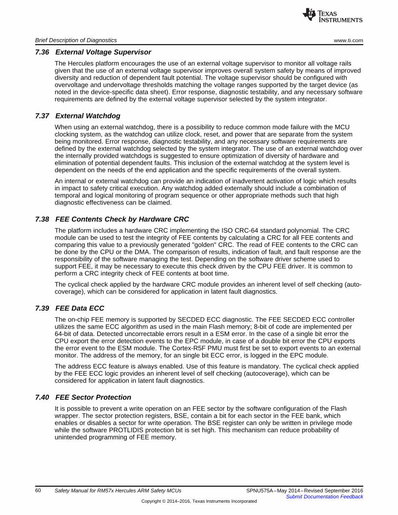
Brief Description of Diagnostics www.ti.com
60 SPNU575A–May 2014–Revised September 2016Submit Documentation Feedback
Copyright © 2014–2016, Texas Instruments Incorporated
Safety Manual for RM57x Hercules ARM Safety MCUs
7.36 External Voltage SupervisorThe Hercules platform encourages the use of an external voltage supervisor to monitor all voltage railsgiven that the use of an external voltage supervisor improves overall system safety by means of improveddiversity and reduction of dependent fault potential. The voltage supervisor should be configured withovervoltage and undervoltage thresholds matching the voltage ranges supported by the target device (asnoted in the device-specific data sheet). Error response, diagnostic testability, and any necessary softwarerequirements are defined by the external voltage supervisor selected by the system integrator.
7.37 External WatchdogWhen using an external watchdog, there is a possibility to reduce common mode failure with the MCUclocking system, as the watchdog can utilize clock, reset, and power that are separate from the systembeing monitored. Error response, diagnostic testability, and any necessary software requirements aredefined by the external watchdog selected by the system integrator. The use of an external watchdog overthe internally provided watchdogs is suggested to ensure optimization of diversity of hardware andelimination of potential dependent faults. This inclusion of the external watchdog at the system level isdependent on the needs of the end application and the specific requirements of the overall system.
An internal or external watchdog can provide an indication of inadvertent activation of logic which resultsin impact to safety critical execution. Any watchdog added externally should include a combination oftemporal and logical monitoring of program sequence or other appropriate methods such that highdiagnostic effectiveness can be claimed.
7.38 FEE Contents Check by Hardware CRCThe platform includes a hardware CRC implementing the ISO CRC-64 standard polynomial. The CRCmodule can be used to test the integrity of FEE contents by calculating a CRC for all FEE contents andcomparing this value to a previously generated "golden" CRC. The read of FEE contents to the CRC canbe done by the CPU or the DMA. The comparison of results, indication of fault, and fault response are theresponsibility of the software managing the test. Depending on the software driver scheme used tosupport FEE, it may be necessary to execute this check driven by the CPU FEE driver. It is common toperform a CRC integrity check of FEE contents at boot time.
The cyclical check applied by the hardware CRC module provides an inherent level of self checking (auto-coverage), which can be considered for application in latent fault diagnostics.
7.39 FEE Data ECCThe on-chip FEE memory is supported by SECDED ECC diagnostic. The FEE SECDED ECC controllerutilizes the same ECC algorithm as used in the main Flash memory; 8-bit of code are implemented per64-bit of data. Detected uncorrectable errors result in a ESM error. In the case of a single bit error theCPU export the error detection events to the EPC module, in case of a double bit error the CPU exportsthe error event to the ESM module. The Cortex-R5F PMU must first be set to export events to an externalmonitor. The address of the memory, for an single bit ECC error, is logged in the EPC module.
The address ECC feature is always enabled. Use of this feature is mandatory. The cyclical check appliedby the FEE ECC logic provides an inherent level of self checking (autocoverage), which can beconsidered for application in latent fault diagnostics.
7.40 FEE Sector ProtectionIt is possible to prevent a write operation on an FEE sector by the software configuration of the Flashwrapper. The sector protection registers, BSE, contain a bit for each sector in the FEE bank, whichenables or disables a sector for write operation. The BSE register can only be written in privilege modewhile the software PROTLIDIS protection bit is set high. This mechanism can reduce probability ofunintended programming of FEE memory.

www.ti.com Brief Description of Diagnostics
61SPNU575A–May 2014–Revised September 2016Submit Documentation Feedback
Copyright © 2014–2016, Texas Instruments Incorporated
Safety Manual for RM57x Hercules ARM Safety MCUs
7.41 Flash Address and Control Bus ParityThe CPU bus interconnect to Flash memory (CPU Interconnect Subsystem) is supported by a paritydiagnostic on the address and control signals. The parity is generated by the CPU and evaluated by theFlash wrapper. Detected errors are signaled to the ESM by the Flash wrapper and the error address iscaptured in the Flash wrapper.
This diagnostic is enabled at reset. The diagnostic can be disabled by programmation of theBUS_PAR_DIS key in the FPAR_OVR register of the Flash wrapper.
7.42 Flash Contents Check by Hardware CRCThe platform includes a hardware cyclic redundancy check (CRC) implementing the ISO CRC-64 standardpolynomial. The CRC module can be used to test the integrity of Flash contents by calculating a CRC forall Flash contents and comparing this value to a previously generated "golden" CRC. The read of Flashcontents to the CRC can be done by CPU or the DMA. The comparison of results, indication of fault, andfault response are the responsibility of the software managing the test. It is a common approach toperform a CRC integrity check of Flash contents at boot time.
The cyclical check applied by the hardware CRC module provides an inherent level of self checking (auto-coverage), which can be considered for application in latent fault diagnostics.
7.43 Flash ECCThe on-chip Flash memory is supported by single error correction, dual error detection (SECDED)errorcorrecting code (ECC) diagnostic. It is connected by a 64-bit-wide data bus interface to the CPUInterconnect Subsystem. In this SECDED scheme, an 8-bit code word is used to store the ECC data ascalculated over the 64-bit data bus.
The ECC logic for the Flash access is located in the bus masters in case of the CPU or the in the CPUInterconnect Subsystem for other master such as the DMA and the TU's. All Flash transactions have ECCon the data payload. ECC evaluation is done by the ECC control logic inside the bus master or the CPUInterconnect Subsystem. This scheme provides end-to-end diagnostics on the transmissions between thebus master and Flash memory. Detected uncorrectable errors result in a ESM error. In the case of asingle bit error the CPU export the error detection events to the EPC module, in case of a double bit errorthe CPU exports the error event to the ESM module. The Cortex-R5F PMU must first be set to exportevents to an exhttp://infocenter.arm.com/help/topic/com.arm.doc.ddi0460d/index.htmlternal monitor. Theaddress of the memory, for a single bit ECC error, is logged in the EPC module. For more details on theECC implementation in the CPU bus master, see the Cortex-R5 and Cortex-R5F Technical ReferenceManual located at .
The ECC is always enabled for the Flash. The cyclical check applied by the ECC logic provides aninherent level of self checking (autocoverage), which can be considered for application in latent faultdiagnostics.
7.44 Flash Hard Error Cache and LivelockIf ECC correction is enabled, corrected data values are stored in an internal one entry hard error cache. Itis not possible to automatically re-write the corrected data values back to the Flash, as the Flash is a non-volatile memory that has special programming requirements.
A single instruction and its data may not have more than one correctable error. In case more than onecorrectable error is detected, it is possible to overrun the hard error cache and put the processor into aninoperable livelock state. Cases that can generate a livelock include:• Two single bit errors in a 64-bit unaligned 32-bit Thumb-2 instruction fetch• A single bit error in a load instruction (LDR or LDM) followed by a single bit error in the instruction's
data payload
Livelock is indicated via the ESM and typically requires a reset for recovery to be attempted. Livelock on aFlash interface transaction can be an indication of severe permanent fault in the Flash memory.
This feature is enabled at reset and cannot be disabled by the software.

Brief Description of Diagnostics www.ti.com
62 SPNU575A–May 2014–Revised September 2016Submit Documentation Feedback
Copyright © 2014–2016, Texas Instruments Incorporated
Safety Manual for RM57x Hercules ARM Safety MCUs
7.45 Flash Sector ProtectionIt is possible to prevent a write operation on a sector by the software configuration of the Flash wrapper.The sector protection registers, Bank Sector Enable Register (BSE), contain a bit for each sector in theFlash bank, which enables or disables a sector for write operation. The BSE register can only be written inprivilege mode while the software PROTLIDIS protection bit is set high. This mechanism can reduceprobability of unintended programming of Flash memory.
7.46 Flash Wrapper Address ECCIn addition to the ECC functionality in the CPU, the flash wrapper extends the ECC capability to includeaddress. The standard SECDED ECC scheme utilized has 8-bit of code for 64-bit of data. Extensions ofthe Hamming equations allow additional bits of data beyond 64 bits to be encoded into 8 bits of code withthe same Hamming distance. The flash wrapper design takes advantage of this by incorporating theaddress of the transaction into the Flash memory ECC data. All values stored in the Flash memory havethe address added into the Flash ECC. Upon read of data from Flash, the flash wrapper will strip theaddress component from the ECC and provide the regenerated ECC code to the bus master. Errors in theaddress can result in a multi-bit ECC failure as seen by the bus master.
The address ECC feature is always enabled. The cyclical check applied by the flash wrapper addressECC module provides an inherent level of self checking (autocoverage), which can be considered forapplication in latent fault diagnostics.
7.47 Flash Wrapper Diag Mode 5 TestAn error can be inserted into the lockstep address tag registers to cause a mismatch between primary andduplicate registers. This diag mode can be used to test the Primary Flash interface.
7.48 Flash Wrapper Diag Mode 7 TestIn order to test the ECC logic of the CPU incorrect ECC can be fed into the CPU. In this diagnostic modeone or more specific bits can be flipped. This diag mode can be used to test the Primary Flash interface.
7.49 Glitch Filtering on nRST and nPORRSTGlitch filters are implemented on the cold and warm reset pins of the device. These structures filter outnoise and transient signal spikes on the input reset pins in order to reduce unintended activation of thereset circuitry. The glitch filters are continuously operating and their behavior cannot be changed by thesoftware.
7.50 Hardware CRC Check of External MemoryThe contents of external memories connected to the EMIF can be tested periodically using the hardwareCRC-64 diagnostic. This diagnostic is especially useful for static memory contents, but is less useful if thememory contents change dynamically in application. For more details on this diagnostic, see SRAMHardware CRC-64.
7.51 Hardware CRC Check of OTP ContentsThe platform includes a hardware cyclic redundancy check (CRC) implementing the ISO CRC-64 standardpolynomial. The CRC module can be used to test the integrity of OTP contents by calculating a CRC forall Flash contents and comparing this value to a previously generated "golden" CRC. The read of Flashcontents to the CRC can be done by the CPU or the DMA. The comparison of results, indication of fault,and fault response are the responsibility of the software managing the test. OTP is loaded at boot timeand a CRC check of OTP at boot time is an effective method of ensuring proper device configuration atboot up.
7.52 Hardware Disable of JTAG PortThe JTAG debug port can be physically disabled to prevent JTAG access in deployed systems. The mostprevalent scheme is to hold test clock (TCK) to ground and hold test mode select (TMS) high, thoughalternate schemes are possible.

www.ti.com Brief Description of Diagnostics
63SPNU575A–May 2014–Revised September 2016Submit Documentation Feedback
Copyright © 2014–2016, Texas Instruments Incorporated
Safety Manual for RM57x Hercules ARM Safety MCUs
Disabling of the JTAG port also provides coverage for inadvertent activation of many debug activities,since these are often initiated via an external debug tool which writes commands to the device using theJTAG port.
7.53 Information Redundancy TechniquesInformation redundancy techniques can be applied via software as an additional runtime diagnostic for thismodule. There are many techniques that can be applied, such as read back of written values and multipleoutput of the same data with comparison of results. Error response, diagnostic testability, and anynecessary software requirements are defined by the software implemented by the system integrator.
7.54 Information Redundancy Techniques - CPU SpecificInformation redundancy techniques can be applied via software as an additional runtime diagnostic on theCPU execution. There are many techniques that can be applied, such as redundant execution usingdiverse algorithms with comparison of results. Error response, diagnostic testability, and any necessarysoftware requirements are defined by the software implemented by the system integrator.
7.55 Information Redundancy Techniques - DCAN SpecificInformation redundancy techniques can be applied via software as an additional runtime diagnostic forCAN communication. There are many techniques that can be applied, such as read back of written valuesand multiple reads of the same target data with comparison of results.
In order to provide diagnostic coverage for network elements outside the MCU (wiring harness,connectors, transceiver) end-to-end safing mechanisms are applied. These mechanisms can also providediagnostic coverage inside the MCU. There are many different schemes applied, such as additionalmessage checksums, redundant transmissions, time diversity in transmissions, and so forth. Mostcommonly checksums are added to the payload section of a transmission to ensure the correctness of atransmission. These checksums are applied in addition to any protocol level parity and checksums. As thechecksum is generated and evaluated by the software at either end of the communication, the wholecommunication path is safed, resulting in end-to-end safing.
Error response, diagnostic testability, and any necessary software requirements are defined by the systemintegrator.
7.56 Information Redundancy Techniques - DMA SpecificInformation redundancy techniques can be applied using the DMA module. There are many techniquesthat can be applied, such as read back of written values and multiple reads of the same target data withcomparison of results.
Error response, diagnostic testability, and any necessary software requirements are defined by thesoftware implemented by the system integrator.
7.57 Information Redundancy Techniques - N2HET SpecificInformation redundancy techniques can be applied via software or system as an additional runtimediagnostic on N2HET operations. There are many techniques that can be applied, such as multiplesampling of a single input channel, sampling of two or more input channels, and read back of writtenoutput. Splitting functionality between the two implemented N2HET modules can provide reducedprobability of common mode failure as opposed to implementing a function and its diagnostic on a singleN2HET.
Error response, diagnostic testability, and any necessary software requirements are defined by thesoftware implemented by the system integrator.

Brief Description of Diagnostics www.ti.com
64 SPNU575A–May 2014–Revised September 2016Submit Documentation Feedback
Copyright © 2014–2016, Texas Instruments Incorporated
Safety Manual for RM57x Hercules ARM Safety MCUs
7.58 Internal Voltage Monitor (VMON)The Hercules platform incorporates a simple embedded voltage monitor (VMON) that can detect grosslyout of range supply voltages. The VMON operates continuously and requires no software configuration orCPU overhead. VMON monitors the core and I/O supplies. When the supplies are grossly over or underspecified voltages (for product specific values, see the device-specific data sheet), the VMON drives thenPORRST (power-on reset) signal internally. This response holds the device in the safe operating state.When power supplies are in range, the VMON will not interfere with the nPORRST signal. For moreinformation on VMON operation, see the device-specific data sheet.
The VMON is a continuously operating diagnostic. It is not possible to disable the VMON diagnostic. In-system test of the VMON diagnostic is generally not feasible as tight control of external voltages is neededto trigger the VMON error response. If improperly applied, such voltage could result in permanent damageto the MCU.
7.59 Internal WatchdogThe Hercules platform supports the use of an internal watchdog that is implemented in the real timeinterrupt (RTI) module. The internal watchdog has two modes of operation: digital watchdog (DWD) anddigital windowed watchdog (DWWD). The modes of operation are mutually exclusive, the designer canelect to use one mode or the other but not both at the same time. For details of programming the internalwatchdogs, see the device-specific technical reference manual.
The DWD is a traditional single threshold watchdog. The user programs a timeout value to the watchdogand must provide a predetermined "pet" response to the watchdog before the timeout counter expires.Expiration of the timeout counter or an incorrect "pet" response triggers an error response. The DWD canissue either an internal (warm) system reset or a CPU non-maskable interrupt upon detection of a failure.The DWD is not enabled after reset. Once enabled by the software, the DWD cannot be disabled exceptby system reset or power-on reset. Users should take care not to change the DWD clock source afterenabling the module, else behavior is unpredictable.
The DWWD is a traditional windowed watchdog. The user programs an upper bound and lower bound tocreate a time window during which the software must provide a predetermined "pet" response to thewatchdog. Failure to receive the correct response within the time window or an incorrect "pet" responsetriggers an error response. The DWWD can issue either an internal (warm) system reset or a CPU non-maskable interrupt upon detection of a failure. The DWWD is not enabled after reset. Once enabled by thesoftware, the DWWD cannot be disabled except by system reset or power-on reset. The use of the timewindow allows detection of additional clocking failure modes as compared to the DWD implementation.
An internal or external watchdog can provide an indication of inadvertent activation of logic which resultsin impact to safety critical execution, such as an inadvertent activation of JTAG logic.
7.60 IOMM Master ID FilteringThe IOMM checks the master ID of all incoming bus transactions. Only transactions from the CPU areallowed. Illegal transactions result in a bus error response to the offending bus master and the write toIOMM will be discarded. This feature is enabled after reset. Software cannot disable this feature.
7.61 LIN Checksum Error DetectionAfter message reception, the LIN performs a CRC check on all received data bytes. This data is thencompared to the checksum for the message that was transmitted by the sender. If there is a mismatch,the LIN hardware can flag a Checksum Error and generate an interrupt to the CPU. This feature must beenabled and configured in software.
7.62 LIN No-Response Error DetectionIf no response is received within a configurable time period after the LIN master completes a headertransmission, the LIN hardware can flag a No-Response Error and generate an interrupt to the CPU. Thisfeature must be enabled and configured in software.

www.ti.com Brief Description of Diagnostics
65SPNU575A–May 2014–Revised September 2016Submit Documentation Feedback
Copyright © 2014–2016, Texas Instruments Incorporated
Safety Manual for RM57x Hercules ARM Safety MCUs
7.63 LIN Physical Bus Error DetectionIf no message can be generated on the LIN Bus, the LIN hardware can flag the error and generate aphysical bus error and generate an interrupt to the CPU. This feature must be enabled and configured insoftware.
7.64 LIN / SCI Bit Error DetectionWhen this module transmits information on the LIN Bus, it also monitors the LIN Bus to ensure that thetransmitted information is appearing as expected on the LIN Bus. If the expected values are not read backfrom the LIN Bus, the hardware can flag the error and signal an interrupt to the CPU. This feature must beenabled and configured in software.
7.65 LIN / SCI Frame Error DetectionWhen receiving serial data, each byte of information on the SCI has an expected format. If the receivedmessage does not match this error, the SCI hardware can flag an error and generate an interrupt to theCPU. This feature must be enabled and configured in software.
7.66 LIN / SCI Overrun Error DetectionIf the SCI RX buffer receives new data before the previous data has been read, the existing data will beoverwritten and lost. If this occurs, the SCI hardware can flag the error and generate an interrupt to theCPU. This feature must be enabled and configured in software.
7.67 Locking Mechanism for Control RegistersThe IOMM contains a two stage lock mechanism for protection of critical control registers. To change theconfiguration of the pin multiplexing, the user must write two specific 32-bit values to the "kicker" registersin a defined sequence. When complete, the lock function must be reset. Write accesses, when theregisters are locked, will not update the registers, nor will they generate an error response. This feature isenabled after reset. Software can disable the lock by unlocking and never re-locking.
7.68 Lockout of JTAG Access Using AJSMThe Hercules platform includes the Advanced JTAG Security Module (AJSM) as support for managingdebug access on deployed devices. AJSM can be used to program a unique access key to the OTP Flashmemory. Subsequent debug accesses must unlock the AJSM with the correct key sequence in order togain access to the JTAG-based debug, trace, and calibration logic. An error in unlocking the AJSM resultsin no error response and no access to the debug logic.
7.69 Low Power Oscillator Clock Detector (LPOCLKDET)The low-power oscillator clock detector (LPOCLKDET) is a safety diagnostic that can be used to detectfailure of the primary clock oscillator. LPOCLKDET utilizes the embedded high-frequency, low-poweroscillator (HF LPO). The clock detect circuit works by checking for a rising edge on one clock (oscillator orHF LPO) between rising edges of the other clock. The result is that in addition to flagging incorrect,repeating frequencies, the circuit also fails due to transient conditions. The low end of the clock detectwindow ignores a transient low phase of at least 12 HF LPO cycles. Note that this filtering of the transientresponse does not change the input frequency range. The LPOCLKDET circuitry is enabled by defaultduring the power-on reset state. The diagnostic can be disabled via software.
7.70 Memory Protection Unit (MPU) for Non-CPU Bus MastersMany non-CPU bus masters include an MPU. The MPU logic can be used to provide spatial separation ofsoftware tasks in the device memory. It is expected that the module's software driver controls the MPUand changes the MPU settings based on the needs of system implementation. A violation of a configuredmemory protection policy will result in an ESM error. The MPU is not enabled at reset. Software mustenable, configure and test the MPU.

Brief Description of Diagnostics www.ti.com
66 SPNU575A–May 2014–Revised September 2016Submit Documentation Feedback
Copyright © 2014–2016, Texas Instruments Incorporated
Safety Manual for RM57x Hercules ARM Safety MCUs
7.71 MibADC CalibrationThe Hercules MibADC module implements calibration logic normally used to improve converter accuracy.This logic can also be used as a safety mechanism. Software comparison of the conversion of knownreference values from the calibration logic can provide a diagnostic on converter functionality. Repeatedexecution of the calibration routine can be used to detect drift during application. Software must configureand enable and evaluate the result of this diagnostic. Error response, diagnostic testability, and anynecessary software requirements are defined by the software implemented by the system integrator.
7.72 MibADC Information Redundancy TechniquesInformation redundancy techniques can be applied via software as an additional runtime diagnostic onADC conversions. There are many techniques that can be applied, such as multiple conversions usingshared channels and using both converters, using multiple channels on the same converter or by doingmultiple conversions on the same channel followed with comparison of results. Filtering or a plausibilitycheck for the converted values are in expected range can also improve diagnostic coverage. Errorresponse, diagnostic testability, and any necessary software requirements are defined by the softwareimplemented by the system integrator.
7.73 MibADC Input Self-TestThe Hercules MibADC module implements an input self-test engine that can detect short to ADREFLO,ADREFHI or open input. Software must configure and enable and evaluate the result of this diagnostic.Error response, diagnostic testability, and any necessary software requirements are defined by thesoftware implemented by the system integrator.
7.74 MibSPI/SPI Data Length Error DetectionThe MibSPI or SPI can detect an error in the length of either a received or a transmitted message. If thetransmitted or received message does not match the expected length as specified in the charactercounter, the MibSPI or SPI module can flag a Data Length error and signal an interrupt to the CPU. Thisfeature must be enabled and configured in software.
7.75 MibSPI/SPI Data Overrun DetectionIf the MibSPI or SPI RX buffer receives new data before the previous data has been read, the existingdata will be overwritten and lost. If this occurs, the MibSPI or SPI hardware can flag the error andgenerate an interrupt to the CPU. This feature must be enabled and configured in software.
7.76 MibSPI/SPI Slave Desync DetectionWhen a slave module supports the generation of an enable signal (ENA), slave de-synchronization can bedetected. De-synchronization occurs when the slave misses one or more MibSPI or SPI clock edgescoming from the master during transmission. In this case the slave would continue to wait for theremaining clock edges, while holding the ENA signal active. The MibSPI can detect this condition throughthe use of a configurable counter which starts after message transmission is complete. If the ENA signalcoming from the slave does not become inactive by the time the counter overflows, the MibSPI or SPImodule can flag a slave desynch error and signal an interrupt to the CPU. This feature must be enabledand configured in software.
7.77 MibSPI/SPI Slave Timeout DetectionWhen a slave supports the generation of an enable signal (ENA), slave timeout can be detection. Slavetimeout occurs when the SPI Master generates a handshake signal to indicate the beginning of atransmission, but the slave does not respond. The MibSPI or SPI can detect this condition through the useof a configurable counter which starts after the handshake transmission. If the slave does not respond byactivating the ENA signal by the time the counter expires, the MibSPI or SPI module can flag a SlaveTimeout error and signal an interrupt to the CPU. This feature must be enabled and configured insoftware.

www.ti.com Brief Description of Diagnostics
67SPNU575A–May 2014–Revised September 2016Submit Documentation Feedback
Copyright © 2014–2016, Texas Instruments Incorporated
Safety Manual for RM57x Hercules ARM Safety MCUs
7.78 Monitoring by Second N2HETThe N2HET supports an internal channel connection between the two N2HET modules to facilitate easymonitoring of one N2HET by a second N2HET. This feature is supported as a convenience to limit thenumber of functional channels at device level, which must be utilized for diagnostic purposes. Alternativelyexternal connections can be used. Error response, diagnostic testability, and any necessary softwarerequirements are defined by the software implemented by the system integrator.
7.79 Monitoring by eCAP or N2HETThe ePWM outputs can be monitored for proper operation by an input capture peripheral, such as theeCAP or an N2HET channel configured as an input capture. In most cases the connection betweenePWM output and monitoring input capture peripheral must be made externally. In some products it maybe possible to enable an internal connection using the I/O pin multiplexing logic. Error response,diagnostic testability, and any necessary software requirements are defined by the software implementedby the system integrator.
7.80 Non-Privileged Bus Master AccessThis module is a non-privileged bus master. Since writes to critical configuration registers across the MCUis limited to privileged mode transactions only, this mechanism prevents inadvertent configuring of theseregisters by this module. The operation of this safety mechanism is continuous and cannot be altered bythe software. This mechanism can be tested by generating software transactions and reviewing the deviceresponse.
7.81 OTP Autoload ECCThe OTP autoload controller utilizes a SECDED ECC diagnostic to detect (and correct) incorrectconfiguration values. The OTP autoload is executed after every power-on reset. Errors are indicated viaESM. The cyclical check applied by the ECC logic provides an inherent level of self checking (auto-coverage), which can be considered for application in latent fault diagnostics.
7.82 Parity in MessageThis module supports insertion of a parity bit into the data payload of every outgoing MIBSPI message byhardware. Evaluation of incoming message parity is also supported by hardware. Detected errorsgenerate an interrupt to the CPU.
7.83 Periodic Hardware CRC Check of OTP ContentsThe platform includes a hardware cyclic redundancy check (CRC) implementing the ISO CRC-64 standardpolynomial. The CRC module can be used to test the integrity of OTP contents by calculating a CRC forall Flash contents and comparing this value to a previously generated "golden" CRC. The read of Flashcontents to the CRC can be done by CPU or the DMA. The comparison of results, indication of fault, andfault response are the responsibility of the software managing the test. The cyclical check applied by thehardware CRC module provides an inherent level of self checking (auto-coverage), which can beconsidered for application in latent fault diagnostics.
7.84 PCR Access Management: Protection Mode and MasterID FilteringThe peripheral central resource (PCR) provides three safety mechanisms that can limit access toperipherals: clock gating, access privileges, and master ID filtering.
In the case of clock gating the peripheral central resource can be used for clock gated per peripheral chipselect in the PCR. This can be utilized to disable unused features such that they cannot interfere withactive safety functions.
In addition, each peripheral chip select can be programmed to limit access based on privilege level oftransaction. This feature can be used to limit access to entire peripherals to privileged operating systemcode only.

Brief Description of Diagnostics www.ti.com
68 SPNU575A–May 2014–Revised September 2016Submit Documentation Feedback
Copyright © 2014–2016, Texas Instruments Incorporated
Safety Manual for RM57x Hercules ARM Safety MCUs
Finally, the PCR can be used to limit access to selected peripherals by specific bus masters usingmasterID filtering. This mechanism provides each PCR segment with the capability to filter transactionsfrom each one of its bus masters to each one of its peripheral selects. This is to provide an additional levelof protection for the slaves at a peripheral segment level (PCR1, PCR2, PCR3).
These safety mechanisms are disabled after reset. Software must configure and enable thesemechanisms.
7.85 Periodic Hardware CRC Check of SRAM ContentsThe platform includes a hardware CRC implementing the ISO CRC-64 standard polynomial. The CRCmodule can be used to test the integrity of static contents in the SRAM by calculating a CRC for all staticcontents and comparing this value to a previously generated "golden" CRC. The read of SRAM contentsto the CRC can be done by CPU or by DMA. The comparison of results, indication of fault, and faultresponse are the responsibility of the software managing the test. The cyclical check applied by the CRClogic provides an inherent level of self checking (auto-coverage), which can be considered for applicationin latent fault diagnostics.
7.86 Periodic Software Read Back of Static Configuration RegistersPeriodic read back of configuration registers can provide a diagnostic for inadvertent writes or disturb ofthese registers. Error response, diagnostic testability, and any necessary software requirements aredefined by the software implemented by the system integrator.
7.87 Peripheral SRAM ParityThis module's SRAM includes a parity diagnostic that can detect single bit errors in the memory. When aparity error is detected, the ESM is notified. This feature is disabled after reset. Software must configureand enable this feature.
7.88 Peripheral Memory ECCThis module's memory includes an ECC diagnostic that can correct single bit and detect double bit errorsin the memory. When an ECC error is detected the ESM is notified. This feature is disabled after reset.Software must configure and enable this feature.
7.89 PLL Slip DetectorThe PLL logic includes an embedded diagnostic that can detect a slip of the PLL output clock. The slip isa result of a loss of phase lock between reference clock and feedback clock. Error response and indicationis dependent on the programming of the PLL control registers that are located in the system controlmodule. ESM error indication can be generated or masked. In addition, it is possible to generate aninternal reset or to revert to operation from the oscillator clock in case of a detected error. For moreinformation on programming this diagnostic, see the device-specific technical reference manual.
The PLL slip detection diagnostic is active whenever the PLL is enabled and has locked on a targetfrequency. The diagnostic cannot be disabled by the software, but the error indication and error responsecan be modified by the software.
7.90 Primary SRAM Address and Control Bus ParityThe on-chip transactions to SRAM are supported by a parity diagnostic on the address and controlsignals. The parity is generated by the bus master and evaluated by the SRAM. Detected errors aresignaled to the ESM by the SRAM. This diagnostic is enabled at reset. The diagnostic can be disabled byasserting the address parity disable key in the RAMCTRL register of the SRAM wrapper.
This diagnostic is enabled at reset. The diagnostic can be disabled by assertion of the address paritydisable key in the RAMCTRL register of the SRAM wrapper.

www.ti.com Brief Description of Diagnostics
69SPNU575A–May 2014–Revised September 2016Submit Documentation Feedback
Copyright © 2014–2016, Texas Instruments Incorporated
Safety Manual for RM57x Hercules ARM Safety MCUs
7.91 Primary SRAM Data and ECC Storage in Multiple Physical Banks per LogicalAddressEach logical SRAM word and its associated ECC code is split and stored in two physical SRAM banks.Each access comprises 72 total bits - 64 bits of data and 8 bits of ECC code. This is split in half, with eachphysical SRAM storing 32 bits of data and 4 bits of ECC code.
This scheme provides an inherent safety mechanism for address decode failures in the physical SRAMbanks. Faults in the bank addressing are detected by the CPU as an ECC fault. This feature is enabled atreset and cannot be disabled by the software.
7.92 Primary SRAM Correctable ECC ProfilingAn SRAM ECC profiling feature is provided by the EPC. The EPC provides a unified correctable ECCerror (single bit ECC fault) profiling capability and error address cache on ECC failures in SRAM. Thismechanism is disabled by default and must be enabled by the software. Cortex-R5F PMU export of eventsmust also be enabled for this function to operate.
7.93 ECC on Cache RAMECC on Cache Memories - The ARM Cortex R5F processor supports ECC on L1 cache SRAMs for bothinstruction and data caches. For more information, see the Cortex-R5 and Cortex-R5F TechnicalReference Manual located at http://infocenter.arm.com/help/topic/com.arm.doc.ddi0460d/index.html.
7.94 Primary SRAM Data ECCThe on-chip SRAM is supported by SECDED ECC diagnostics. It is connected by a 64-bit-wide data businterface. In this SECDED scheme, an 8-bit code word is used to store the ECC data as calculated overthe 64-bit data bus.
The ECC logic for the SRAM access is located in the bus masters as well as in the SRAM wrapper forsub-word accesses. All memory interconnect (CPU Interconnect Subsystem) transactions have ECC onthe data payload. The ECC generation and evaluation logic is located in the bus masters in case of theCPU or in the CPU Interconnect Subsystem for other masters such as the DMA and the TUs. Thisscheme provides end-to-end diagnostics on the transmissions between bus master and SRAM on theCPU Interconnect Subsystem. Detected uncorrectable errors result in a ESM error. In the case of a singlebit error the CPU exports the error detection events to the EPC module, in case of a double bit error theCPU exports the error event to the ESM module. The Cortex-R5F PMU must first be set to export eventsto an external monitor. The address of the memory, for any single bit ECC error, is logged in the EPCmodule. For more details on the ECC controller inside the CPU, see the Cortex-R5 and Cortex-R5FTechnical Reference Manuall located athttp://infocenter.arm.com/help/topic/com.arm.doc.ddi0460d/index.html.
The ECC logic for the SRAM is always enabled in both bus masters and the wrapper. In case of sub-64bit word accesses the RAM wrapper will evaluate and check the ECC on the data payload. This iscontrolled via software in the SRAM wrapper. The cyclical check applied by the ECC logic provides aninherent level of self checking (autocoverage), which can be considered for application in latent faultdiagnostics.
7.95 Primary SRAM Wrapper Redundant Address DecodeThe SRAM wrapper includes a diagnostic to check for errors in the address decode logic. The diagnosticimplements a checker copy of the address decode logic in lockstep to the functional address decode logic.The SRAM wrapper includes comparator logic to detect differences in the output from the two addressdecoders. Any detected mismatch will be signaled to the ESM and the address will be captured to a localregister.
The redundant address decode logic diagnostic is active after reset. The diagnostic is supported by ahardware self-test that is triggered via software. The compare function is disabled during self-testoperation.

Brief Description of Diagnostics www.ti.com
70 SPNU575A–May 2014–Revised September 2016Submit Documentation Feedback
Copyright © 2014–2016, Texas Instruments Incorporated
Safety Manual for RM57x Hercules ARM Safety MCUs
7.96 Primary SRAM Hard Error Cache and LivelockIf correction is enabled, corrected data values are stored in an internal one entry hard error cache,rewritten to the SRAM, and re-fetched from the SRAM.
A single instruction and its data may not have more than one correctable error. In case more than onecorrectable error is detected, it is possible to overrun the hard error cache and put the processor into aninoperable livelock state. Cases that can generate a livelock include:• Two single bit errors in a 64-bit unaligned 32-bit Thumb-2 instruction fetch• A single bit error in a load instruction (LDR or LDM) followed by a single bit error in the instruction's
data payload
Livelock is indicated via the ESM and typically requires a reset for recovery to be attempted. Livelock on aSRAM interface transaction can be an indication of severe permanent fault in the SRAM. This feature isenabled at reset and cannot be disabled by the software.
7.97 Privileged Mode Access and Multi-Bit Enable Keys for Control RegistersThis module includes features to support avoidance of unintentional control register programming. Thesefeatures include limitation of write commands to privilege bus master transactions and the implementationof multi-bit keys for critical controls. The multi-bit keys are particularly effective for avoiding unintentionalactivation. For more details on the register safety mechanisms and error response, see the device-specifictechnical reference manual.
The operation of this safety mechanism is continuous and cannot be altered by the software. Thismechanism can be tested by generating software transactions and reviewing the device response.
7.98 PBIST Check of Primary or Module SRAMThe Hercules family architecture supports the use of a hardware programmable memory BIST (PBIST)engine. This logic is used to provide a very high diagnostic coverage on the implemented SRAMs at atransistor level. This logic utilizes the same design for test (DFT) logic and algorithms used by TI toprovide rapid execution of high quality manufacturing tests. This technique has proven to be drasticallymore effective than software-based tests of SRAM, particularly for the devices with complex CPUs whoseaddressing modes do not enable an optimal software-based test.
The PBIST tests must be triggered by the software. A developer can elect to run all algorithms, or only asubset of the algorithms based on the execution time that can be allocated to the PBIST diagnostic.Similarly, the user can elect to run the PBIST on one SRAM or on groups of SRAMs based on theexecution time, which can be allocated to the PBIST diagnostic. The PBIST tests are destructive tomemory contents, and as such are typically run only at MCU initialization. However, the user has thefreedom to initiate the tests at any time when the CPU is operable.
Execution of the PBIST results in a much higher level of transistor switching per clock cycle than duringnormal software execution due to the high efficiency of the test. A software control is implemented in thePBIST that allows the user to reduce the SRAM clock for the duration of the test. This feature allows theuser to make a compromise between fast execution with higher current consumption or slower executionwith reduced current consumption.
The most effective SRAM tests known to TI require test across a full physical memory module and aredestructive to previous memory contents. If PBIST is to be implemented during operation, it is possible toretain SRAM content by copying the data from the SRAM to be tested to a non-tested memory before testexecution and to restore the data once the test is complete. When test execution is complete, the SRAMcan be utilized for normal operation. The remainder of device logic continues normal operation duringSRAM test. Any fault detected by the PBIST results in an error indicated in PBIST status registers. It isalso possible to log faults in the PBIST logic.
PBIST logic includes capabilities for testing proper operation of the diagnostic. As the test time for thediagnostic is deterministic, a timeout counter can be implemented via software configuration of RTImodule so that it can detect a failure to complete the test within an expected time. In addition, there is thepossibility to test the contents of the ROM that contains the PBIST algorithms via running a checksumROM test using the PBIST engine. Error forcing can be accomplished by executing a test not intended fora targeted memory, such as executing an SRAM read and write test on the PBIST ROM.

www.ti.com Brief Description of Diagnostics
71SPNU575A–May 2014–Revised September 2016Submit Documentation Feedback
Copyright © 2014–2016, Texas Instruments Incorporated
Safety Manual for RM57x Hercules ARM Safety MCUs
7.99 PBIST Auto-coverageThe PBIST diagnostic is based on a 32-bit signature capture. For a given test, only one code is valid outof 2^32 possibilities. Therefore, if there is a fault in the PBIST logic, it is extremely unlikely that the correctpassing code will be generated via the fault.
7.100 Power Domain Inactivity MonitorWhen a power domain is turned off, its outputs are isolated from the rest of the system. The outputs areclamped to inactive safe values. Depending on the signals, the clamp value of a signal may be 0 or 1.Some bus masters may be residing in the turned off power domains. Key bus signals from the powerdomains which would have indicated that the bus master is generating a valid bus transaction arecompared against their clamped values.
The Power Domain Inactivity Monitor Diagnostic can run in one of four user selectable operating modes:Active compare, Self-test , Error forcing, Self-test error forcing
7.101 PBIST Test of Parity Bit MemoryWhen a Programmable Memory Bist (PBIST) test is run on a selected memory, the corresponding paritybit memory will be tested as well. This provides latent coverage for the parity memory as part of the paritydiagnostic.
7.102 PBIST Test of ECC Bit MemoryWhen a Programmable Memory BIST (PBIST) test is run on a selected memory, the corresponding ECCbit memory will be tested as well. This provides latent coverage for the ECC memory as part of the ECCdiagnostic.
7.103 Lockstep PSCONFor each implemented power domain, a power state controller (PSCON) implements the control logic. Inthe Hercules platform, each PSCON is implemented with a diagnostic PSCON, running in lockstep, tocheck for current power state control settings on a cycle-by-cycle basis. Any error detected by lockstepcompare is signaled to the ESM.
The PSCON lockstep compare is enabled by default during the power-on reset state. The PSCONlockstep compare can be disabled by the software in order to test the compare functionality. The test ofthe lockstep comparison feature is supported by a software triggered hardware self-test. The hardwareself-test can initiate comparison tests for both match and mismatch inputs. Error forcing is also possible totest system level error response.
7.104 Redundant Address Decode Self-TestThe redundant address decode diagnostic includes hardware to support self-test. It is possible to force apass and a fail to help diagnose proper operation of the redundant address decode diagnostic.
7.105 Redundant Temperature SensorsThis device contains three temperature sensors for sensing die temperature. 1 sensor is readable usingMibADC1 and 2 are readable with MibADC2 to provide diverse and similar inputs for latent fault detection.As a diagnostic, software can use the 3 temperature sensors in a 2oo3 voting scheme to determine thevalidity of the temperature readings at any given time.
7.106 Scrubbing of SRAM to Correct Detected Single Bit ErrorsThe SRAM wrapper includes logic to enable local correction of detected single bit errors to supportscrubbing operations to repair accumulated faults. The read transactions necessary for the scrubbingoperations must be initiated by a bus master. When activated, this feature exercises the local ECC logic tocorrect single bit failures that may have accumulated in the SRAM.
Brief Description of Diagnostics www.ti.com
72 SPNU575A–May 2014–Revised September 2016Submit Documentation Feedback
Copyright © 2014–2016, Texas Instruments Incorporated
Safety Manual for RM57x Hercules ARM Safety MCUs
7.107 Shadow RegistersThe use of a two stage cold and warm reset scheme on the device allows the implementation of shadowregisters. Shadow registers are reset only by power-on reset. These registers can be used to store devicestatus or other critical information that remain persistent after a warm reset changes the system state. Thismodule includes shadow registers which can be used by software to provide additional information on thestate of the device before the last warm reset operation.
7.108 Software Check of Cause of Last ResetThe system control module provides a status register (SYSESR) that latches the cause of the most recentreset event. A boot software that checks the status of this register to determine the cause of the last resetevent is typically implemented by software developers. This information can be used by the software tomanage failure recovery.
7.109 Software Read Back of CPU RegistersIn order to ensure proper configuration of CPU coprocessor control registers, software can be used toimplement a test to confirm proper operation of all control register writes. The CPU control registers arenot memory mapped and must be accessed via the CPU coprocessor read and write commands.
7.110 Software Read Back of Written ConfigurationIn order to ensure proper configuration of memory-mapped registers, a software test can be implementedto confirm proper operation of all control register writes. To support this software test, the register memoryspace can be configured as a strongly ordered, non-bufferable memory region using the Cortex-R5Fmemory protection unit. Configuration in this manner ensures that the register write by the CPU willcomplete before additional CPU instructions are executed.
7.111 Software Test of DCC FunctionalityA basic test of DCC functionality (including error generation) is possible via software by programming asequence of good and bad expected clock ratios and executing DCC operations with software confirmingexpected results.
7.112 Software Test of DWD FunctionalityA basic test of DWD operation can be performed via software including checking of error response byprogramming expected "pet" thresholds and servicing or not servicing the "pet" requests.
7.113 Software Test of DWWD FunctionalityA basic test of DWWD operation can be performed via software including checking of error response byprogramming expected "pet" windows and servicing or not servicing the "pet" requests.
7.114 Software Test of ECC Profiler (EPC)It is possible to test the functionality of the ECC profiler, (EPC) by performing reads on locations with ECCerrors, and confirming proper operation of the error counters and threshold interrupt.
7.115 Software Test of Error Path ReportingA software test can be utilized to insert diagnostic errors and check for proper reporting. Such a test canbe executed at boot or periodically. Necessary software requirements are defined by the softwareimplemented by the system integrator.
7.116 Software Test of Flash Sector Protection LogicBy attempting to write to a protected flash sector, the operation of flash sector protection logic can betested

www.ti.com Brief Description of Diagnostics
73SPNU575A–May 2014–Revised September 2016Submit Documentation Feedback
Copyright © 2014–2016, Texas Instruments Incorporated
Safety Manual for RM57x Hercules ARM Safety MCUs
7.117 Software Test of Function Including Error TestsA software test can be utilized to test basic functionality as well as to insert diagnostic errors and check forproper error response. Such a test can be executed at boot or periodically. Software requirementsnecessary are defined by the software implemented by the system integrator.
7.118 Software Test of Function Using I/O LoopbackA software test can be utilized to test basic functionality as well as to insert diagnostic errors and check forproper error response. Such a test can be executed at boot or periodically. Software requirementsnecessary are defined by the software implemented by the system integrator.
Most modules support digital and analog loopback capabilities for the I/Os. Refer to the device technicalreference manual to confirm the implemented loopback capabilities of the module. Digital loopback teststhe signal path to the module boundary. Analog loopback tests the signal path from the module to the I/Ocell with output driver enabled. For best results any tests of the functionality should include the I/Oloopback.
7.119 Software Test of Function Using I/O Checking In GIO ModeA software test can be utilized to test basic functionality of the I/O in GIO Mode to perform an analogloopback diagnostic on an I/O pin. Such a test can be executed at boot or periodically. Softwarerequirements necessary are defined by the software implemented by the system integrator.
The GIO buffer architecture supports an analog loopback between the input and output buffers of a givenI/O structure. The content of the data in and data out registers will directly reflect the state of the pinwhether the I/O direction is configured as an input or an output. This configuration allows the software testto detect inconsistencies between known input states or known output states with the pin state.
7.120 Software Test of Function Using I/O Loopback in Transceiver/PHYA software test can be utilized to test basic functionality as well as to insert diagnostic errors and check forproper error response. Such a test can be executed at boot or periodically. Software requirementsnecessary are defined by the software implemented by the system integrator.
Most Ethernet PHYs include a loopback mode that allows testing of the signal path including the PHY.Error response, diagnostic testability, and any necessary software requirements are defined by the systemintegrator. For best results, any tests of the networking functionality should include I/O loopback.
7.121 Software Test of Function Using I/O Loopback Including Error Tests - IOMM OnlyAnalog loopback testing from peripherals results in signals traversing the I/O pin mux logic to the I/O padand can provide diagnostic coverage on the I/O pin mux configuration. Analog loopback tests the signalpath from the module to the I/O cell with the output driver enabled.
I/O loopback is not enabled at reset. Software is necessary to configure and execute the diagnostic. IOconfiguration error response is managed by the software.
IOMM Error Trapping can also be realized during this testing by providing consideration of user accessprivileges and access to un-implemented register addresses. Permission and address violations arereported in the ESM.
7.122 Software Test of Hardware CRCIt is possible to test the functionality of hardware CRC by checking for correct calculation of expected CRCvalues as well as intentionally forcing a mismatch between the data and expected CRC signature. TheSoftware Test of Hardware CRC will validate proper calculation of the CRC as well as correct errorreporting of a mismatch of the calculated CRC by the CRC logic.

Brief Description of Diagnostics www.ti.com
74 SPNU575A–May 2014–Revised September 2016Submit Documentation Feedback
Copyright © 2014–2016, Texas Instruments Incorporated
Safety Manual for RM57x Hercules ARM Safety MCUs
7.123 Software Test of MPU FunctionalityIt is possible to test the functionality of the non-CPU bus master MPUs by checking for correct memoryaccess to a programmed region as well as by marking a memory region as invalid and then attempting towrite to it in order to generate an error. If the MPU features discrimination by read/write then the testingshould also consider checking for correct operation and errors related to read/write permissions.
7.124 Software Test of Parity LogicIt is possible to test the functionality of parity error detection logic by forcing a parity error into the data orparity memory bits, and observing whether the parity error detection logic reports an error. Parity can alsobe calculated manually and compared to the hardware calculated value stored in the parity memory bits.
7.125 Software Test of PBISTIt is possible to configure the PBIST logic by selecting an algorithm that should fail, and seeing if thePBIST Logic reports an error under this condition. For example, a read-write test could be performed on aread-only memory to ensure that a failure is reported. An alternative scheme is to run a test for memorywith more bits than are actually present on the device memory.
7.126 Software Test of SRAM Wrapper Address Decode Diagnostic and ECCA software based test of the redundant address decode diagnostic and ECC error reporting logic in theSRAM wrapper can be performed at boot time as a latent diagnostic.
7.127 Software Test for ResetA software test for detecting basic functionality as well as errors for reset sources and reset logic can beimplemented.
7.128 Software Warm Reset GenerationThe system control module provides the ability to the software to generate an internal warm reset (nRST).This is accomplished by writing appropriate control bits in the SYSECR control register. Software canutilize this feature to attempt failure recovery.
7.129 Transmission RedundancyUsing transmission redundancy, information is transferred several times in sequence and compared. If thesame data path is used for the duplicate transmissions, then transmission redundancy will only by usefulfor detecting transient faults. Error response, diagnostic testability, and any necessary softwarerequirements are defined by the system integrator.
7.130 Use of CoreSight Debug Logic Key Enable SchemeTo enable operation of the memory-mapped CoreSight debug components, it is necessary to write adefined 32-bit key to an unlock register in each debug module. This debug lock protection provides anadditional safety mechanism to limit undesired activation.
7.131 Use of DCC as Program Sequence WatchdogThe design of the N2HET is such that the instruction memory is contiguously executed in a circular loopwith deterministic duration. A clocked output of known frequency can be generated on the N2HET withminimum software overhead. Each N2HET has a dedicated channel internally connected to one of the twoDCC modules. Comparison of the N2HET clocking output to a known clock reference by DCC caneffectively implement a program sequence watchdog on the N2HET. Error response, diagnostic testability,and any necessary software requirements are defined by the software implemented by the systemintegrator.

www.ti.com Brief Description of Diagnostics
75SPNU575A–May 2014–Revised September 2016Submit Documentation Feedback
Copyright © 2014–2016, Texas Instruments Incorporated
Safety Manual for RM57x Hercules ARM Safety MCUs
7.132 Use of MPUs to Block Access to Memory Mapped DebugThe CoreSight and other debug related peripherals are accessible over a memory-mapped debug bus.Access to this region can be blocked via the use of bus master based memory protection. For moreinformation on memory protection, see CPU Memory Protection Unit (MPU).
7.133 Execution of Interconnect Self-TestThe CPU Interconnect Subsystem can be put into self-test. During self-test, the self-test logic applies teststimulus to each master and slave interface of the CPU interconnect Subsystem . If an error is detected,the type of error for the corresponding interface is logged in the CPU Interconnect Subsystem memorymapped register and an error is asserted to ESM. The interconnect is not available for functional usewhen the self-test is applied. This test can be ran at boot time or periodically within the application.
7.134 CPU Interconnect Hardware CheckerFor each master and slave interface in the CPU interconnect Subsystem, there is a runtime hardwaresafety diagnostic checker. The hardware checker continuously monitors the transactions flowing throughthe interconnect and ensures that they are not corrupted . If a mismatch is detected between an ongoingtransaction and the expected transaction flow then an error is asserted to the ESM. This diagnostic candetect issues with arbitration, routing, and timeout of transactions. The type of error is recorded in theinterconnect memory mapped registers
7.135 Timeout Monitoring on The Bus TransactionThe CPU Interconnect Subsystem contains timeout counters to count the amount of time it is taking for amaster request to be accepted by the slave and also to count the amount of time it takes from anaccepted request to the slave response. There are two separate counters per master interface. Wheneither the request-to-accept counter or the accept-to-response counter expires by the slave, a timeouterror is asserted to the ESM.
7.136 Transaction ECC (Data Lines)The CPU core contains the built-in ECC generation and evaluation logic for its AXI interface. Therefore,the CPU will generate the ECC checksum for the data lines along with its write data. The write data andthe corresponding ECC checksum are transported by the interconnect to the selected slave such as L2(primary) SRAM. When the CPU core performs a read from a slave, the slave returns the data and thecorresponding Data ECC checksum. Upon receiving the data and the ECC checksum, the CPU willevaluate the integrity of the data by performing the Data ECC check. Data ECC errors detected on theCPU's AXI interface are exported by the CPU to its event bus output. The error signals, if enabled, andthe corresponding error addresses are first routed to the Error Profiling Controller (EPC) module. EPC isused to record different single bit error addresses in a Content Addressable Memory (CAM). The mainpurpose of the EPC module is to enable the system to tolerate a certain amount of ECC correctable errorson the same address repeated in the memory system with minimal runtime overhead. If an ECC error isgenerated on a repeating address, the EPC will not raise an error to the ESM module. This toleranceallows the application to avoid the handling of the same error when the code is in a repeating loop.
DMA PortA and Peripheral Interconnect Subsystem masters do not have built-in ECC generation andevaluation logic. Therefore, the CPU Interconnect Subsystem contain a standalone ECC generation andevaluation logic for each DMA PortA and Peripheral Interconnect Subsystem master. Write transactionsinitiated by the DMA PortA and Peripheral Interconnect Subsystem masters are first treated by the ECCblock to generate the ECC checksum before transporting to the final destination. For read transactions,the data and ECC checksum returned by the slaves will pass through the ECC block for data integrityevaluation. ECC errors detected are also routed to the Error Profiling Controller (EPC) module. In order forthe standalone ECC block to assert the error signals to the EPC, the error enable key must be first set inthe IP1ECCERREN register of the SYS2 module.
ECC errors detected are also routed to the Error Profiling Controller (EPC) module. In order for thestandalone ECC block to assert the error signals to the EPC, the error enable key must be first set in theIP1ECCERREN register of the SYS2 module.

Brief Description of Diagnostics www.ti.com
76 SPNU575A–May 2014–Revised September 2016Submit Documentation Feedback
Copyright © 2014–2016, Texas Instruments Incorporated
Safety Manual for RM57x Hercules ARM Safety MCUs
7.137 Transaction Parity (Address and Control Lines)The CPU core contains the built-in parity generation and evaluation logic for its AXI interface. Therefore,the CPU will generate the Parity for the Address and Control Lines along with its write data. The write dataand the corresponding Address and Control Line Parity are transported by the interconnect to the selectedslave such as L2 (primary) SRAM. When the CPU core performs a read from a slave, the slave returnsthe data and the corresponding Address and Control Line Parity. Upon receiving the data and the Addressand Control Line Parity information, the CPU will evaluate the integrity of the data by performing theAddress and Control Line Parity check. Parity errors detected on the CPU's AXI interface are exported bythe CPU to its event bus output.
7.138 Peripheral Interconnect New Memory Protection Unit (NMPU)An NMPU module is implemented to provide memory protection for transactions that are initiated bymasters on the Peripheral Interconnect Subsystem which target slaves on the CPU InterconnectSubsystem. This module is disabled by default and must be enabled by software.
7.139 Software Test of The New Memory Protection Unit (NMPU) FunctionalityIt is possible to initiate a software test of the NMPU functionality. Similar to, but a subset of the CPU MPU,the NMPU offers up 8 protection regions ranging in size from 32-bytes to 4GB in size. The actual numberof protection regions vary by IP with DMA having 8, Peripheral Interconnect Subsystem having 8, andEMIF having 2. Each region can have programmable access permissions such as full access, readaccess, or write access. In addition, different access permissions can be assigned by user and privilegemodes of operation. Software tests can be made to exercise these access regions using the variousmasters and defined access permissions. In practice, it is most effective to initiate both positive andnegative testing where a master is tested to insure proper access to allowed regions with the appropriatetype of access and also tested for areas of illegal access and illegal access types. This type of boundarylevel testing provides the most comprehensive test of the functionality.
7.140 Software Test of ECC LogicIt is possible to test the functionality of ECC error detection logic by forcing an ECC error into the data orECC memory bits, and observing whether the ECC error detection logic reports an error. ECC can also becalculated and compared to the hardware calculated value stored in the ECC memory bits.
7.141 Multi-Bit Keyed Self-Correctable High-Integrity BitsThere are a limited number of registers in the device that have been identified as having a critical role indevice operation integrity with respect to a safety system. These register bits are designated as high-integrity bits and have been implemented with error correcting logic such that each bit, although read andwritten as a single bit, is actually a multi-bit key with ECC capability. As such, single bit flips within the“key” can be corrected allowing protection of the system as a whole. Double bit flips within thesestructures are flagged as an error and signaled through the ESM. For more information on specificregisters and bits that utilize this bit structure, please reference the device TRM.

www.ti.com Next Steps in Your Safety Development
77SPNU575A–May 2014–Revised September 2016Submit Documentation Feedback
Copyright © 2014–2016, Texas Instruments Incorporated
Safety Manual for RM57x Hercules ARM Safety MCUs
8 Next Steps in Your Safety DevelopmentTI's support for your safety development does not stop with the delivery of this safety document.Customers have a wide range of support options, such as:• Access safety collateral for Hercules and other SafeTI™ products at: http://www.ti.com/safeti• Access Hercules documentation including safety docs and app notes any time on the web:
http://www.ti.com/hercules• Discuss questions and concerns with TI experts and other Hercules developers using the TI
Connected Community (E2E forums): http://www.ti.com/hercules-support• Discuss questions and concerns regarding TI's safety documents that are provided under NDA with TI
safety experts at: https://e2eprivate.ti.com/safeti_functional_safety_support/default.aspx. By requestinga copy of this document, access will be granted to the support forum as well here:http://www.ti.com/safetyanalysis
• The Hercules Wiki page provides answers to many commonly asked questions:http://www.ti.com/hercules-wiki
• Attend a training class delivered by TI's Hercules experts: http://www.ti.com/herculestraining
Feedback and concerns about the safety manual are always welcome and can be submitted via the webby clicking on the feedback link at the bottom of each page of this document.

78 SPNU575A–May 2014–Revised September 2016Submit Documentation Feedback
Copyright © 2014–2016, Texas Instruments Incorporated
Summary of Safety Feature Usage
Appendix ASPNU575A–May 2014–Revised September 2016
Summary of Safety Feature Usage
Table 4 provides a summary of the safety features and diagnostics present in hardware or available forimplementation in software or at system level.
Table 3. Key to Summary of Safety Features and Diagnostics
Device Partition This field provides the element (device partition) which has safety features anddiagnostics
Unique Identifier This field provides a short unique identifier to aid in traceability of each safety featuresand diagnostics
Safety Feature or Diagnostic This field provides the name of the safety feature or diagnostic.Possible Tests for Diagnostics This column lists mechanisms that can be applied to verify that the diagnostic itself is
functioning correctly.Usage Each test listed in this chart can be one of two types. A "diagnostic" test, or a "test-for-
diagnostic only" testDiagnostic: Provides coverage for faults on a primary function of the device. It may, inaddition, provide fault coverage on other diagnostics, and can therefore be also used as atest-for-diagnostic in certain casesTest-for-Diagnostic Only: Does NOT provide coverage for faults on a primary function ofthe device. It's only purpose is to provide fault coverage on other diagnostics
Diagnostic Type Hardware: A diagnostic or test-for-diagnostic which is implemented by TI in silicon. It mayrequire software activationSoftware: A diagnostic or test-for-diagnostic which is performed in software and whichmust be created by the software implementorSoftware-Hardware: A diagnostic or test-for-diagnostic which requires both hardware inthe device and software created by the software implementorSystem: A diagnostic or test-for-diagnostic which must be implemented at the systemlevel by the system implementor
Diagnostic Operation Continuous or Periodic/On-DemandText Execution Time This column lists the time that is required for this diagnostic to completeAction on Detected Fault The response that this diagnostic takes when an error is detected.
For software-driven tests, this action if often software implementation-dependentError Reporting Time Typical time required for diagnostic to indicate a detected fault to the system.
For software-driven tests, this time is often software implementation-dependent

www.ti.com Appendix A
79SPNU575A–May 2014–Revised September 2016Submit Documentation Feedback
Copyright © 2014–2016, Texas Instruments Incorporated
Summary of Safety Feature Usage
Table 4. Summary of Safety Features and Diagnostics
Device PartitionUnique
Identifier Safety Feature or Diagnostic Possible Tests for Diagnostics UsageDiagnosticType
DiagnosticOperation
TextExecutionTime
Action onDetected Fault Error Reporting Time
Power Supply
PWR1 Internal Voltage Monitor (VMON) PWR2: External Voltage SupervisorCLK5C: External Watchdog Diagnostic Hardware Continuous
1 µs(Glitch filter logicfilters transientglitches of <1 µs)
Assert component power-onreset until fault condition notdetectionsystem control module ResetRequest Register will log thecause of reset
Reset action <1 µS afterdetectionSoftware indication of resetcause available on firstCPU active clock
PWR2 External Voltage SupervisorPWR1: Internal Voltage Monitor(VMON)CLK5C: External Watchdog
Diagnostic SystemSystem Defined(TypicallyContinuous)
System DefinedSystem Defined (Typically thepowered device is disabledvia reset or power cut)
System Defined
Power MgtModule (PMM)
PMM1 Lockstep PSCON PMM5: PSCON LockstepComparator Self Testt Diagnostic Hardware Continuous No Hardware
OverheadTrigger to ESM group1 andset local error flag
Typically <1 µS to notifyCPU**(Interrupt handling time issystem load and softwaredependent)
PMM2 Privileged-Mode Access and Multi-BitKeys for Control Registers N/A Diagnostic Hardware Continuous No Hardware
OverheadControl registers will not beupdated N/A (Fault Avoidance)
PMM3 Periodic Software Readback of StaticConfiguration Registers
CLK5A: Internal Watchdog - DWDCLK5B: Internal Watchdog - DWWDCLK5C: External WatchdogCPU1: CPU Lockstep CompareFLA1: Flash Data ECCRAM1: RAM Data ECC
Diagnostic Software Periodic / On-Demand
SoftwareDependentTypically <25 CPUclocks per 32-bitRegister Read
Software Dependent Software Dependent
PMM4 Software Readback of WrittenConfiguration
CLK5A: Internal Watchdog - DWDCLK5B: Internal Watchdog - DWWDCLK5C: External WatchdogCPU1: CPU Lockstep CompareFLA1: Flash Data ECCRAM1: RAM Data ECC
Diagnostic Software Periodic / On-Demand
SoftwareDependentTypically <25 CPUclocks per 32-bitRegister Read
Software Dependent Software Dependent
PMM5 PSCON Lockstep Comparator SelfTestt
NA - This is a test of the PSCONdiagnostic. It is not a diagnostic itself
Test-for-DiagnosticOnly
Hardware Periodic / On-Demand 24 Clock cycles Trigger to ESM group1 and
set local error flag
Typically <1 µS to notifyCPU**(Interrupt handling time issystem load and softwaredependent)
PMM6 Power Domain Inactivity Monitor
CLK5A: Internal Watchdog - DWDCLK5B: Internal Watchdog - DWWDCLK5C: External WatchdogCPU1: CPU Lockstep Compare
Diagnostic Hardware Continuous No HardwareOverhead
Trigger to ESM group 12 andset local error flag in theCCM-R5 module
Typically <1 µS to notifyCPU**(Interrupt handling time issystem load and softwaredependent)

Appendix A www.ti.com
80 SPNU575A–May 2014–Revised September 2016Submit Documentation Feedback
Copyright © 2014–2016, Texas Instruments Incorporated
Summary of Safety Feature Usage
Table 4. Summary of Safety Features and Diagnostics (continued)
Device PartitionUnique
Identifier Safety Feature or Diagnostic Possible Tests for Diagnostics UsageDiagnosticType
DiagnosticOperation
TextExecutionTime
Action onDetected Fault Error Reporting Time
Clock
CLK1 LPOCLKDET CLK5C: External WatchdogCLK4: External Monitoring via ECLK Diagnostic Hardware Continuous No Hardware
Overhead
Error event provided to ESMOptional MCU soft (warm)reset generationOptional clock source switchto LPO
Typically <1 µS to notifyCPU**(Interrupt handling time issystem load and softwaredependent)
CLK2 PLL Slip Detector CLK5C: External WatchdogCLK4: External Monitoring via ECLK Diagnostic Hardware Continuous No Hardware
Overhead
Error Event Provided to ESMOptional MCU Soft (warm)Reset GenerationOptional Clock Source Switchto LPO
Typically <1 µS to notifyCPU**(Interrupt handling time issystem load and softwaredependent)
CLK3 Dual Clock Comparator (DCC)
CLK6: Periodic Software Readback ofStatic Configuration RegistersCLK5C: External WatchdogCLK4: External Monitoring via ECLK
Diagnostic Software-Hardware Continuous Software
Dependent Error Event Provided to ESM
Typically <1 µS to notifyCPU**(Interrupt handling time issystem load and softwaredependent)
CLK4 External Monitoring via ECLK System Dependent Diagnostic System Continuous No HardwareOverhead System Defined System Defined
CLK5A Internal Watchdog - DWD
CLK9: Software Test of DWDOperationCLK5C: External WatchdogCLK4: External Monitoring via ECLK
Diagnostic Software-Hardware Continuous
No HardwareOverhead -SoftwareDependent
Internal MCU Soft (warm)Reset
Reset reason available inSYS module on first clockafter reset
CLK5B Internal Watchdog - DWWD
CLK9: Software Test of DWDOperationCLK5C: External WatchdogCLK4: External Monitoring via ECLK
Diagnostic Software-Hardware Continuous
No HardwareOverhead -SoftwareDependent
Internal MCU Soft (warm)Reset or Non-MaskableInterrupt
Reset reason available inSYS module on first clockafter resetTypically <1 µS to notifyCPU of NMI**(Interrupt handling time issystem load and softwaredependent)
CLK5C External Watchdog System Dependent Diagnostic Software-Hardware Continuous System Dependent System Defined System Defined
CLK6 Periodic Software Readback of StaticConfiguration Registers
CLK5A: Internal Watchdog - DWDCLK5B: Internal Watchdog - DWWDCLK5C: External WatchdogCPU1: CPU Lockstep CompareFLA1: Flash Data ECCRAM1: RAM Data ECC
Diagnostic Software Periodic / On-Demand
SoftwareDependentTypically <25 CPUclocks per 32-bitRegister Read
Software Dependent Software Dependent
CLK7 Software Readback of WrittenConfiguration
CLK5A: Internal Watchdog - DWDCLK5B: Internal Watchdog - DWWDCLK5C: External WatchdogCPU1: CPU Lockstep CompareFLA1: Flash Data ECCRAM1: RAM Data ECC
Diagnostic Software Periodic / On-Demand
SoftwareDependentTypically <25 CPUclocks per 32-bitRegister Read
Software Dependent Software Dependent
CLK8 Software Test of DCC Operation NA - This is a test of the DCCdiagnostic. It is not a diagnostic itself
Test-for-DiagnosticOnly
Software Periodic / On-Demand
SoftwareDependent Software Dependent Software Dependent
CLK9 Software Test of DWD Operation NA - This is a test of the DWDdiagnostic. It is not a diagnostic itself
Test-for-DiagnosticOnly
Software Periodic / On-Demand
SoftwareDependent Software Dependent Software Dependent
CLK10 Software Test of DWWD Operation NA - This is a test of the DWWDdiagnostic. It is not a diagnostic itself
Test-for-DiagnosticOnly
Software Periodic / On-Demand
SoftwareDependent Software Dependent Software Dependent

www.ti.com Appendix A
81SPNU575A–May 2014–Revised September 2016Submit Documentation Feedback
Copyright © 2014–2016, Texas Instruments Incorporated
Summary of Safety Feature Usage
Table 4. Summary of Safety Features and Diagnostics (continued)
Device PartitionUnique
Identifier Safety Feature or Diagnostic Possible Tests for Diagnostics UsageDiagnosticType
DiagnosticOperation
TextExecutionTime
Action onDetected Fault Error Reporting Time
Reset
RST1 External Monitoring of Warm Reset(nRST) System Dependent Diagnostic System
System Defined(TypicallyContinuous)
System DefinedSystem Defined (Typically thepowered device is disabledvia reset or power cut)
System Defined
RST2 Software Check of Cause of LastReset N/A Diagnostic Software -
HardwarePeriodic / On-Demand
SoftwareDependent N/A (Fault Avoidance) N/A (Fault Avoidance)
RST3 Software Warm Reset Generation N/A Diagnostic Software -Hardware
Periodic / On-Demand
SoftwareDependent N/A (Fault Avoidance) N/A (Fault Avoidance)
RST4 Glitch Filtering on Reset Pins N/A Diagnostic Hardware Continuous
1 µs(Glitch filter logicfilters transientglitches of <1 µs
N/A (Fault Avoidance) N/A (Fault Avoidance)
RST5 Use of Status Shadow Registers N/A Diagnostic Software -Hardware
Periodic / On-Demand
SoftwareDependent N/A (Fault Avoidance) N/A (Fault Avoidance)
RST6 Periodic Software Readback of StaticConfiguration Registers
CLK5A: Internal Watchdog - DWDCLK5B: Internal Watchdog - DWWDCLK5C: External WatchdogCPU1: CPU Lockstep CompareFLA1: Flash Data ECCRAM1: RAM Data ECC
Diagnostic Software Periodic / On-Demand
SoftwareDependentTypically <25 CPUclocks per 32-bitRegister Read
Software Dependent Software Dependent
RST7 Software Readback of WrittenConfiguration
CLK5A: Internal Watchdog - DWDCLK5B: Internal Watchdog - DWWDCLK5C: External WatchdogCPU1: CPU Lockstep CompareFLA1: Flash Data ECCRAM1: RAM Data ECC
Diagnostic Software Periodic / On-Demand
SoftwareDependentTypically <25 CPUclocks per 32-bitRegister Read
Software Dependent Software Dependent
RST8 Software Test for Reset
CLK5A: Internal Watchdog - DWDCLK5B: Internal Watchdog - DWWDCLK5C: External WatchdogCPU1: CPU Lockstep CompareFLA1: Flash Data ECCRAM1: RAM Data ECC
Diagnostic Software -Hardware
Periodic / On-Demand
Software-DependentHardwarecontribution to testexecution time isnegligible
Software Dependent Software Dependent
System ControlModule
SYS1 Privileged Mode Access and Multi-BitEnable Keys for Control Registers N/A Diagnostic Hardware Continuous No Hardware
Overhead Control Register not Updated N/A (Fault Avoidance)
SYS2 Software Readback of WrittenConfiguration
CLK5A: Internal Watchdog - DWDCLK5B: Internal Watchdog - DWWDCLK5C: External WatchdogCPU1: CPU Lockstep CompareFLA1: Flash Data ECCRAM1: RAM Data ECC
Diagnostic Software Periodic / On-Demand
SoftwareDependentTypically <25 CPUclocks per 32-bitRegister Read
Software Dependent Software Dependent
SYS3 Periodic Software Readback of StaticConfiguration Registers
CLK5A: Internal Watchdog - DWDCLK5B: Internal Watchdog - DWWDCLK5C: External WatchdogCPU1: CPU Lockstep CompareFLA1: Flash Data ECCRAM1: RAM Data ECC
Diagnostic Software Periodic / On-Demand
SoftwareDependentTypically <25 CPUclocks per 32-bitRegister Read
Software Dependent Software Dependent
SYS4 Multi-Bit Keyed Self-CorrectableHigh-Integrity Bits N/A Diagnostic Hardware Continuous No Hardware
OverheadControl Register not Updated(Fault Avoidance)
Typically less than 5 cyclesto ESM

Appendix A www.ti.com
82 SPNU575A–May 2014–Revised September 2016Submit Documentation Feedback
Copyright © 2014–2016, Texas Instruments Incorporated
Summary of Safety Feature Usage
Table 4. Summary of Safety Features and Diagnostics (continued)
Device PartitionUnique
Identifier Safety Feature or Diagnostic Possible Tests for Diagnostics UsageDiagnosticType
DiagnosticOperation
TextExecutionTime
Action onDetected Fault Error Reporting Time
Error SignalingModule(ESM)
ESM1 Periodic Software Readback of StaticConfiguration Registers
CLK5A: Internal Watchdog - DWDCLK5B: Internal Watchdog - DWWDCLK5C: External WatchdogCPU1: CPU Lockstep CompareFLA1: Flash Data ECCRAM1: RAM Data ECC
Diagnostic Software Periodic / On-Demand
SoftwareDependentTypically <25 CPUclocks per 32-bitRegister Read
Software Dependent Software Dependent
ESM2A Boot Time Software Test of ErrorPath Reporting
CLK5A: Internal Watchdog - DWDCLK5B: Internal Watchdog - DWWDCLK5C: External WatchdogCPU1: CPU Lockstep CompareFLA1: Flash Data ECCRAM1: RAM Data ECC
Diagnostic Software -Hardware
Periodic / On-Demand
Software-DependentHardwarecontribution to testexecution time isnegligible
Software Dependent Software Dependent
ESM2B Periodic Software Test of Error PathReporting
CLK5A: Internal Watchdog - DWDCLK5B: Internal Watchdog - DWWDCLK5C: External WatchdogCPU1: CPU Lockstep CompareFLA1: Flash Data ECCRAM1: RAM Data ECC
Diagnostic Software -Hardware
Periodic / On-Demand
Software-DependentHardwarecontribution to testexecution time isnegligible
Software Dependent Software Dependent
ESM3 Use of Status Shadow Registers N/A Diagnostic Hardware Continuous N/A - FaultAvoidance N/A - Fault Avoidance N/A - Fault Avoidance
ESM4 Software Readback of WrittenConfiguration
CLK5A: Internal Watchdog - DWDCLK5B: Internal Watchdog - DWWDCLK5C: External WatchdogCPU1: CPU Lockstep CompareFLA1: Flash Data ECCRAM1: RAM Data ECC
Diagnostic Software Periodic / On-Demand
SoftwareDependentTypically <25 CPUclocks per 32-bitRegister Read
Software Dependent Software Dependent
Cortex-R5F CentralProcessing Unit(CPU)
CPU1 CPU Lockstep Compare CPU8: Lockstep Comparator (CCM)Self Test Diagnostic Hardware Continuous 2 CPU Cycles ESM Error
Typically <1 µs(implementationdependent)
CPU2A Boot Time Execution of LBIST STCCPU1: CPU Lockstep CompareCLK5C: External WatchdogCPU9: LBIST Auto-Coverage
Diagnostic Hardware Periodic / On-Demand
Device Dependent(see the device-specific data sheet)
Error Flag AssertedTypically <1 µs(implementationdependent)
CPU2B Periodic Execution of LBIST STCCPU1: CPU Lockstep CompareCLK5C: External WatchdogCPU9: LBIST Auto-Coverage
Diagnostic Hardware Periodic / On-Demand
Device Dependent(see the device-specific data sheet)
Error Flag AssertedTypically <1 µs(implementationdependent)
CPU3 Memory Protection Unit (MPU)
CPU1: CPU Lockstep CompareCPU2A: Boot Time Execution ofLBIST STCCPU2B: Periodic Execution of LBISTSTC
Diagnostic Hardware Continuous No HardwareOverhead Instruction Abort/Data Abort 1 CPU Cycle After
Detection
CPU4 Online Profiling Using PMU
CPU1: CPU Lockstep CompareCPU2A: Boot Time Execution ofLBIST STCCPU2B: Periodic Execution of LBISTSTC
Diagnostic Software-Hardware Continuous Software
Dependent Software Defined Software-Dependent

www.ti.com Appendix A
83SPNU575A–May 2014–Revised September 2016Submit Documentation Feedback
Copyright © 2014–2016, Texas Instruments Incorporated
Summary of Safety Feature Usage
Table 4. Summary of Safety Features and Diagnostics (continued)
Device PartitionUnique
Identifier Safety Feature or Diagnostic Possible Tests for Diagnostics UsageDiagnosticType
DiagnosticOperation
TextExecutionTime
Action onDetected Fault Error Reporting Time
Cortex-R5F CentralProcessing Unit(CPU)
CPU5 CPU Illegal Operation and InstructionTrapping
CPU1: CPU Lockstep CompareCPU2A: Boot Time Execution ofLBIST STCCPU2B: Periodic Execution of LBISTSTC
Diagnostic Hardware Continuous No HardwareOverhead Instruction Abort/Data Abort 1 CPU Cycle After
Detection
CPU6 Periodic Software Readback of StaticConfiguration Registers
CLK5A: Internal Watchdog - DWDCLK5B: Internal Watchdog - DWWDCLK5C: External WatchdogCPU1: CPU Lockstep CompareFLA1: Flash Data ECCRAM1: RAM Data ECC
Diagnostic Software Periodic / On-Demand
SoftwareDependentTypically <25 CPUclocks per 32-bitRegister Read
Software Dependent Software Dependent
CPU7 Software Read Back of CPURegisters
CPU1: CPU Lockstep CompareCPU2A: Boot Time Execution ofLBIST STCCPU2B: Periodic Execution of LBISTSTC
Diagnostic Software Periodic / On-Demand
SoftwareDependentTypically <25 CPUclocks per 32-bitRegister Read
Software Dependent Software Dependent
CPU8 Lockstep Comparator (CCM) SelfTest
NA - This is a test of the CCMdiagnostic,. It is not a diagnostic itself
Test-for-DiagnosticOnly
Hardware Periodic / On-Demand
Device Dependent(see the device-specific data sheet)
Error Flag AssertedTypically <1 µs(implementationdependent)
CPU9 LBIST Auto-Coverage NA - This is a test of the LBISTdiagnostic. It is not a diagnostic itself
Test-for-DiagnosticOnly
Hardware Periodic / On-Demand
N/A; implicit inLBIST operation N/A N/A
CPU10 Boot Time PBIST Check of CPUcache Memories
RAM1: SRAM Data ECCCPU15: Software Readback ofWritten Configuration (PBIST)CPU13: Software Test of PBISTCPU14: PBIST Auto-CoverageCPU1: CPU Lockstep CompareCLK5C: External WatchdogFLA1: Flash Data ECC
Diagnostic Hardware Periodic / On-Demand
Device Dependent(see the device-specific data sheet)
Flag Set in Error Register Software Dependent
CPU11 Periodic PBIST Check of CPU cacheMemories
RAM1: SRAM Data ECCCPU15: Software Readback ofWritten Configuration (PBIST)CPU13: Software Test of PBISTCPU14: PBIST Auto-CoverageCPU1: CPU Lockstep CompareCLK5C: External WatchdogFLA1: Flash Data ECC
Diagnostic Hardware Periodic / On-Demand
Device Dependent(see the device-specific data sheet)
Flag Set in Error Register Software Dependent
CPU12 ECC on Cache Memories CPU1: CPU Lockstep Compare Diagnostic Hardware Continuous 2 CPU Cycles ESM ErrorTypically <1 µs(implementationdependent)
CPU13 Software Test of PBIST NA - This is a test of the PBISTdiagnostic. It is not a diagnostic itself
Test-for-DiagnosticOnly
Software Periodic / On-Demand
SoftwareDependent Software Dependent Software Dependent
CPU14 PBIST Auto-Coverage NA - This is a test of the PBISTdiagnostic. It is not a diagnostic itself
Test-for-DiagnosticOnly
Hardware Periodic / On-Demand
N/A; implicit inPBIST operation N/A N/A
CPU15 Software Readback of WrittenConfiguration (PBIST)
NA - This is a test of the PBISTdiagnostic. It is not a diagnostic itself
Test-for-DiagnosticOnly
Software Periodic / On-Demand
SoftwareDependent Software Dependent Software Dependent

Appendix A www.ti.com
84 SPNU575A–May 2014–Revised September 2016Submit Documentation Feedback
Copyright © 2014–2016, Texas Instruments Incorporated
Summary of Safety Feature Usage
Table 4. Summary of Safety Features and Diagnostics (continued)
Device PartitionUnique
Identifier Safety Feature or Diagnostic Possible Tests for Diagnostics UsageDiagnosticType
DiagnosticOperation
TextExecutionTime
Action onDetected Fault Error Reporting Time
Primary Flash
FLA1 Flash Data ECC
CPU1: CPU Lockstep CompareFLA10: Flash Wrapper Diag Mode 5TestFLA11: Flash Wrapper Diag Mode 7Test
Diagnostic Hardware Continuous No HardwareOverhead CPU Abort / ESM Event Same CPU clock cycles as
data used
FLA2 Hard Error Cache and Livelock CPU1: CPU Lockstep Compare Diagnostic Hardware Continuous No HardwareOverhead Live lock / ESM Event Typically <1 µs
FLA3 Flash Wrapper Address ECC
FLA10: Flash Wrapper Diag Mode 5TestFLA11: Flash Wrapper Diag Mode 7Test
Diagnostic Hardware Continuous No HardwareOverhead CPU Abort / ESM Event Same CPU clock cycles as
data used
FLA4 Address and Control ParityFLA9: Software Readback of WrittenConfigurationFLA12: Software Test of Parity Logic
Diagnostic Hardware Continuous No HardwareOverhead CPU Bus Error Same CPU clock cycles as
data used
FLA5A Boot Time Check of Flash MemoryContents by Hardware CRC
CLK5C: External WatchdogFLA9: Software Readback of WrittenConfigurationFLA14: Software Test of HardwareCRCFLA15: CRC Auto-Coverage
Diagnostic Software -Hardware On Demand
Depends on size ofmemory under test.One 64-bit word perclock cycle plusoverhead.Overhead issoftwaredependent.
Software Defined Software Dependent
FLA5B Periodic Check of Flash MemoryContents by Hardware CRC
CLK5C: External WatchdogFLA9: Software Readback of WrittenConfigurationFLA14: Software Test of HardwareCRCFLA15: CRC Auto-Coverage
Diagnostic Software -Hardware On Demand
Depends on size ofmemory under test.One 64-bit word perclock cycle plusoverhead.Overhead issoftwaredependent.
Software Defined Software Dependent
FLA6 Bit Multiplexing in Flash MemoryArray N/A - Fault Avoidance Diagnostic Hardware Continuous N/A - Fault
Avoidance N/A - Fault Avoidance N/A - Fault Avoidance
FLA7 Flash Sector Protection FLA13: Software Test of Flash SectorProtection Logic Diagnostic Hardware Continuous No Hardware
Overhead Flash Programing Blocked Software dependent basedon readback of content
FLA8 Periodic Software Readback of StaticConfiguration Registers
CLK5A: Internal Watchdog - DWDCLK5B: Internal Watchdog - DWWDCLK5C: External WatchdogCPU1: CPU Lockstep CompareFLA1: Flash Data ECCRAM1: RAM Data ECC
Diagnostic Software Periodic / On-Demand
SoftwareDependentTypically <25 CPUclocks per 32-bitRegister Read
Software Dependent Software Dependent
FLA9 Software Readback of WrittenConfiguration
CLK5A: Internal Watchdog - DWDCLK5B: Internal Watchdog - DWWDCLK5C: External WatchdogCPU1: CPU Lockstep CompareFLA1: Flash Data ECCRAM1: RAM Data ECC
Diagnostic Software Periodic / On-Demand
SoftwareDependentTypically <25 CPUclocks per 32-bitRegister Read
Software Dependent Software Dependent
FLA10 Flash Wrapper Diag Mode 5 Test NA - this is a test of a diagnostic. It isnot a diagnostic itself
Test-for-DiagnosticOnly
Software -Hardware On Demand
SoftwareDependentTypically <1 µsoverhead due tohardware
Software Dependent Software Dependent

www.ti.com Appendix A
85SPNU575A–May 2014–Revised September 2016Submit Documentation Feedback
Copyright © 2014–2016, Texas Instruments Incorporated
Summary of Safety Feature Usage
Table 4. Summary of Safety Features and Diagnostics (continued)
Device PartitionUnique
Identifier Safety Feature or Diagnostic Possible Tests for Diagnostics UsageDiagnosticType
DiagnosticOperation
TextExecutionTime
Action onDetected Fault Error Reporting Time
Primary Flash
FLA11 Flash Wrapper Diag Mode 7 Test NA - this is a test of a diagnostic. It isnot a diagnostic itself
Test-for-DiagnosticOnly
Software -Hardware On Demand
SoftwareDependentTypically <1 µsoverhead due tohardware
Software Dependent Software Dependent
FLA12 Software Test of Parity Logic NA - This is a test of the paritydiagnostic. It is not a diagnostic itself
Test-for-DiagnosticOnly
Software On Demand SoftwareDependent Software Dependent Software Dependent
FLA13 Software Test of Flash SectorProtection Logic
NA - This is a test of the flash sectorprotection logic diagnostic. It is not adiagnostic itself
Test-for-DiagnosticOnly
Software On Demand SoftwareDependent Software Dependent Software Dependent
FLA14 Software Test of Hardware CRCNA - This is a test of the hardwareCRC diagnostic. It is not a diagnosticitself
Test-for-DiagnosticOnly
Software -Hardware
Periodic / On-Demand
Depends on size ofmemory under test.One 64-bit word perclock cycle plusoverhead.Overhead issoftware dependent
Software Dependent Software Dependent
FLA15 CRC Auto-CoverageNA - This is a test of the hardwareCRC diagnostic. It is not a diagnosticitself
Test-for-DiagnosticOnly
Hardware Periodic / On-Demand
N/A; implicit in CRCoperation N/A N/A

Appendix A www.ti.com
86 SPNU575A–May 2014–Revised September 2016Submit Documentation Feedback
Copyright © 2014–2016, Texas Instruments Incorporated
Summary of Safety Feature Usage
Table 4. Summary of Safety Features and Diagnostics (continued)
Device PartitionUnique
Identifier Safety Feature or Diagnostic Possible Tests for Diagnostics UsageDiagnosticType
DiagnosticOperation
TextExecutionTime
Action onDetected Fault Error Reporting Time
Flash EEPROMEmulation(FEE)
FEE1 FEE Data ECC
CPU1: CPU Lockstep CompareFEE15: Flash Wrapper Diag Mode 5TestFEE16: Flash Wrapper Diag Mode 7Test
Diagnostic Hardware Continuous No Overhead(Same clock cycle) ESM Event Same CPU clock cycles as
data used
FEE2A Boot Time Check of FEE MemoryContents by Hardware CRC
FEE6: Software Readback of WrittenConfigurationFEE13: Software Test of HardwareCRCFEE14: CRC Auto-CoverageCLK5C: External Watchdog
Diagnostic Software -Hardware On Demand
Depends on size ofmemory under test.One 64-bit word perclock cycle plusoverhead.Overhead issoftwaredependent.
Software Defined Software Dependent
FEE2B Periodic Check of FEE MemoryContents by Hardware CRC
FEE6: Software Readback of WrittenConfigurationFEE13: Software Test of HardwareCRCFEE14: CRC Auto-CoverageCLK5C: External Watchdog
Diagnostic Software -Hardware On Demand
Depends on size ofmemory under test.One 64-bit word perclock cycle plusoverhead.Overhead issoftwaredependent.
Software Defined Software Dependent
FEE3 Bit Multiplexing in FEE Array N/A - Fault Avoidance Diagnostic Hardware Continuous N/A - FaultAvoidance N/A - Fault Avoidance N/A - Fault Avoidance
FEE4 FEE Sector Protection
FEE2B: Periodic Check of FEEMemory Contents by Hardware CRCFEE12: Software Test of FlashSector Protection Logic
Diagnostic Hardware Continuous No Overhead(Same clock cycle) Flash Programing Blocked Software dependent based
on readback of content
FEE5 Periodic Software Readback of StaticConfiguration Registers
CLK5A: Internal Watchdog - DWDCLK5B Internal Watchdog - DWWDCLK5C: External WatchdogCPU1: CPU Lockstep CompareFLA1: Flash Data ECCRAM1: RAM Data ECC
Diagnostic Software Periodic / On-Demand
SoftwareDependentTypically <25 CPUclocks per 32-bitRegister Read
Software Dependent Software Dependent
FEE6 Software Readback of WrittenConfiguration
CLK5A: Internal Watchdog - DWDCLK5B: Internal Watchdog - DWWDCLK5C: External WatchdogCPU1: CPU Lockstep CompareFLA1: Flash Data ECCRAM1: RAM Data ECC
Diagnostic Software Periodic / On-Demand
SoftwareDependentTypically <25 CPUclocks per 32-bitRegister Read
Software Dependent Software Dependent
FEE7 Flash Wrapper Address ECC
FEE2B: Periodic Check of FEEMemory Contents by Hardware CRCFEE15: Flash Wrapper Diag Mode 5TestFEE16: Flash Wrapper Diag Mode 7Test
Diagnostic Hardware Continuous No HardwareOverhead ESM Event Same CPU clock cycles as
data used

www.ti.com Appendix A
87SPNU575A–May 2014–Revised September 2016Submit Documentation Feedback
Copyright © 2014–2016, Texas Instruments Incorporated
Summary of Safety Feature Usage
Table 4. Summary of Safety Features and Diagnostics (continued)
Device PartitionUnique
Identifier Safety Feature or Diagnostic Possible Tests for Diagnostics UsageDiagnosticType
DiagnosticOperation
TextExecutionTime
Action onDetected Fault Error Reporting Time
Flash EEPROMEmulation(FEE)
FEE12 Software Test of Flash SectorProtection Logic
NA -This is a test of the flash sectorprotection logic diagnostic. It is not adiagnostic itself
Test forDiagnostic Software On Demand Software-
Dependent Software Dependent Software Dependent
FEE13 Software Test of Hardware CRCNA - This is a test of the hardwareCRC diagnostic. It is not a diagnosticitself
Test-for-Diagnostic
Software -Hardware
Periodic / On-Demand
Depends on size ofmemory under test.One 64-bit word perclock cycle plusoverhead.Overhead issoftwaredependent.
Software Dependent Software Dependent
FEE14 CRC Auto-CoverageNA - This is a test of the hardwareCRC diagnostic. It is not a diagnosticitself
Test-for-DiagnosticOnly
Hardware Periodic / On-Demand
N/A; implicit in CRCoperation N/A N/A
FEE15 Flash Wrapper Diag Mode 5 Test NA - this is a test of a diagnostic. It isnot a diagnostic itself
Test forDiagnostic
Software -Hardware On Demand
SoftwareDependentTypically <1 µsoverhead due tohardware
Software Dependent Software Dependent
FEE16 Flash Wrapper Diag Mode 7 Test NA - this is a test of a diagnostic. It isnot a diagnostic itself
Test forDiagnostic
Software -Hardware On Demand
SoftwareDependentTypically <1 µsoverhead due tohardware
Software Dependent Software Dependent

Appendix A www.ti.com
88 SPNU575A–May 2014–Revised September 2016Submit Documentation Feedback
Copyright © 2014–2016, Texas Instruments Incorporated
Summary of Safety Feature Usage
Table 4. Summary of Safety Features and Diagnostics (continued)
Device PartitionUnique
Identifier Safety Feature or Diagnostic Possible Tests for Diagnostics UsageDiagnosticType
DiagnosticOperation
TextExecutionTime
Action onDetected Fault Error Reporting Time
Primary SRAM
RAM1 RAM Data ECC CPU1: CPU Lockstep Compare Diagnostic Hardware Continuous No HardwareOverhead CPU Abort / ESM Event Same CPU clock cycles as
data used
RAM2 Hard Error Cache and Livelock CPU1: CPU Lockstep Compare Diagnostic Hardware Continuous No HardwareOverhead Live lock / ESM Event Typically <1us
RAM3 Correctable ECC Profiling RAM16: Software Test of ECCProfiler Diagnostic Software /
Hardware Continuous SoftwareDependent Software Dependent Software Dependent
RAM4 Address and Control Bus ParityRAM11: Software Readback ofWritten ConfigurationRAM13: Software Test of Parity Logic
Diagnostic Hardware Continuous No HardwareOverhead CPU Bus Error Same CPU clock cycles as
data used
RAM5 Redundant Address Decode RAM17: Redundant Address DecodeSelf Test Diagnostic Hardware Continuous No Hardware
Overhead CPU Bus Error Same CPU clock cycles asdata used
RAM6 Data and ECC Storage in MultiplePhysical Banks N/A - Fault Avoidance Diagnostic Hardware Continuous N/A (Fault
Avoidance) N/A (Fault Avoidance) N/A (Fault Avoidance)
RAM7A Boot Time PBIST Check of PrimarySRAM
RAM14: Software Test of PBISTRAM15: PBIST Auto-CoverageRAM11: Software Readback ofWritten ConfigurationCLK5C: External WatchdogCPU1: CPU Lockstep CompareFLA1: Flash Data ECCRAM1: RAM Data ECC
Diagnostic Hardware Periodic / On-Demand
Device Dependent(see the device-specific data sheet)
Flag Set in Error Register Software Dependent
RAM7B Periodic PBIST Check of PrimarySRAM
RAM14: Software Test of PBISTRAM15: PBIST Auto-CoverageRAM11: Software Readback ofWritten ConfigurationCLK5C: External WatchdogCPU1: CPU Lockstep CompareFLA1: Flash Data ECCRAM1: RAM Data ECC
Diagnostic Hardware Periodic / On-Demand
Device Dependent(see the device-specific data sheet)
Flag Set in Error Register Software Dependent
RAM8 Bit Multiplexing in Primary SRAMArray N/A - Fault Avoidance Diagnostic Hardware Continuous N/A (Fault
Avoidance) N/A (Fault Avoidance) N/A (Fault Avoidance)
RAM9 Periodic Hardware CRC Check ofPrimary SRAM Contents
RAM11: Software Readback ofWritten ConfigurationRAM18: Software Test of HardwareCRCRAM19: CRC Auto-CoverageCLK5C External Watchdog
Diagnostic Software /Hardware
Periodic / On-Demand
Depends on size ofmemory under test.One 64-bit word perclock cycle plusoverhead.Overhead issoftwaredependent.
Software Dependent Software Dependent
RAM10 Periodic Software Readback of StaticConfiguration Registers
CLK5A: Internal Watchdog - DWDCLK5B: Internal Watchdog - DWWDCLK5C: External WatchdogCPU1: CPU Lockstep CompareFLA1: Flash Data ECCRAM1: RAM Data ECC
Diagnostic Software Periodic / On-Demand
SoftwareDependentTypically <25 CPUclocks per 32-bitRegister Read
Software Dependent Software Dependent
RAM11 Software Readback of WrittenConfiguration
CLK5A: Internal Watchdog - DWDCLK5B: Internal Watchdog - DWWDCLK5C: External WatchdogCPU1: CPU Lockstep CompareFLA1: Flash Data ECCRAM1: RAM Data ECC
Diagnostic Software Periodic / On-Demand
SoftwareDependentTypically <25 CPUclocks per 32-bitRegister Read
Software Dependent Software Dependent

www.ti.com Appendix A
89SPNU575A–May 2014–Revised September 2016Submit Documentation Feedback
Copyright © 2014–2016, Texas Instruments Incorporated
Summary of Safety Feature Usage
Table 4. Summary of Safety Features and Diagnostics (continued)
Device PartitionUnique
Identifier Safety Feature or Diagnostic Possible Tests for Diagnostics UsageDiagnosticType
DiagnosticOperation
TextExecutionTime
Action onDetected Fault Error Reporting Time
Primary SRAM
RAM12Software Test of SRAM WrapperRedundant Address Decode andECC
N/A - This is a test of RedundantAddress Decode and ECC. It is not adiagnostic itself
Test-for-DiagnosticOnly
Software Periodic / On-Demand
SoftwareDependent Software Dependent Software Dependent
RAM13 Software Test of Parity Logic N/A - This is a test of the parity logic.It is not a diagnostic itself
Test-for-DiagnosticOnly
Software Periodic / On-Demand
SoftwareDependent Software Dependent Software Dependent
RAM14 Software Test of PBIST NA - This is a test of the PBISTdiagnostic. It is not a diagnostic itself
Test-for-DiagnosticOnly
Software Periodic / On-Demand
SoftwareDependent Software Dependent Software Dependent
RAM15 PBIST Auto-Coverage NA - This is a test of the PBISTdiagnostic. It is not a diagnostic itself
Test-for-DiagnosticOnly
Hardware Periodic / On-Demand
N/A; implicit inPBIST operation N/A N/A
RAM16 Software Test of ECC Profiler NA - This is a test of the ECC profilerdiagnostic. It is not a diagnostic itself
Test-for-DiagnosticOnly
Software Periodic / On-Demand
SoftwareDependent Software Dependent Software Dependent
RAM17 Redundant Address Decode Self Test NA - This is a test of the PBISTdiagnostic. It is not a diagnostic itself
Test-for-DiagnosticOnly
Hardware Periodic / On-Demand
No Overhead(Same clock cycle) Software Dependent Software Dependent
RAM18 Software Test of Hardware CRCNA - This is a test of the hardwareCRC diagnostic. It is not a diagnosticitself
Test-for-DiagnosticOnly
Software /Hardware
Periodic / On-Demand
Depends on size ofmemory under test.One 64-bit word perclock cycle plusoverhead.Overhead issoftwaredependent.
Software Dependent Software Dependent
RAM19 CRC Auto-CoverageNA - This is a test of the hardwareCRC diagnostic. It is not a diagnosticitself
Test-for-DiagnosticOnly
Hardware Periodic / On-Demand
N/A; implicit in CRCoperation N/A N/A
RAM20 Scrubbing of SRAM to CorrectDetected Single Bit Errors N/A - Fault Avoidance
Diagnostic-FaultAvoidance
Hardware Continuous N/A - FaultAvoidance N/A - Fault Avoidance N/A - Fault Avoidance

Appendix A www.ti.com
90 SPNU575A–May 2014–Revised September 2016Submit Documentation Feedback
Copyright © 2014–2016, Texas Instruments Incorporated
Summary of Safety Feature Usage
Table 4. Summary of Safety Features and Diagnostics (continued)
Device PartitionUnique
Identifier Safety Feature or Diagnostic Possible Tests for Diagnostics UsageDiagnosticType
DiagnosticOperation
TextExecutionTime
Action onDetected Fault Error Reporting Time
CPUInterconnectSubsystem
MEM1 Error Trapping (Including PeripheralSlave Error Trapping)
MEM5A: Boot Time Software Test ofBasic Functionality Including ErrorTestsMEM5B: Periodic Software Test ofBasic Functionality Including ErrorTests
Diagnostic Hardware Continuous No HardwareOverhead Bus Error
Bus master notificationtypically <10 clock cyclesafter fault detection
MEM3 Information Redundancy
CLK5A: Internal Watchdog - DWDCLK5B: Internal Watchdog - DWWDCLK5C: External WatchdogCPU1: CPU Lockstep CompareFLA1: Flash Data ECCRAM1: RAM Data ECC
Diagnostic Software Periodic / On-Demand
SoftwareDependent Software Dependent Software Dependent
MEM4 Periodic Software Readback of StaticConfiguration Registers
CLK5A: Internal Watchdog - DWDCLK5B: Internal Watchdog - DWWDCLK5C: External WatchdogCPU1: CPU Lockstep CompareFLA1: Flash Data ECCRAM1: RAM Data ECC
Diagnostic Software Periodic / On-Demand
SoftwareDependentTypically <25 CPUclocks per 32-bitRegister Read
Software Dependent Software Dependent
MEM5A Boot Time Software Test of BasicFunctionality Including Error Tests
CLK5A: Internal Watchdog - DWDCLK5B: Internal Watchdog - DWWDCLK5C: External WatchdogCPU1: CPU Lockstep CompareFLA1: Flash Data ECCRAM1: RAM Data ECC
Diagnostic Software -Hardware
Periodic / On-Demand
Software-DependentHardwarecontribution to testexecution time isnegligible
Software Dependent Software Dependent
MEM5B Periodic Software Test of BasicFunctionality Including Error Tests
CLK5A: Internal Watchdog - DWDCLK5B: Internal Watchdog - DWWDCLK5C: External WatchdogCPU1: CPU Lockstep CompareFLA1: Flash Data ECCRAM1: RAM Data ECC
Diagnostic Software -Hardware
Periodic / On-Demand
Software-DependentHardwarecontribution to testexecution time isnegligible
Software Dependent Software Dependent
MEM6 Software Readback of WrittenConfiguration
CLK5A: Internal Watchdog - DWDCLK5B: Internal Watchdog - DWWDCLK5C: External WatchdogCPU1: CPU Lockstep CompareFLA1: Flash Data ECCRAM1: RAM Data ECC
Diagnostic Software Periodic / On-Demand
SoftwareDependentTypically <25 CPUclocks per 32-bitRegister Read
Software Dependent Software Dependent
MEM7 Transmission Redundancy
CLK5A: Internal Watchdog - DWDCLK5B: Internal Watchdog - DWWDCLK5C: External WatchdogCPU1: CPU Lockstep CompareFLA1: Flash Data ECCRAM1: RAM Data ECC
Diagnostic Software Periodic / On-Demand System Dependent System Dependent System Dependent
MEM8A Boot Time Execution of InterconnectSelf-Test
CLK5A: Internal Watchdog - DWDCLK5B: Internal Watchdog - DWWDCLK5C: External WatchdogCPU1: CPU Lockstep CompareFLA1: Flash Data ECCRAM1: RAM Data ECC
Diagnostic/Test for Diagnostic Hardware Continuous No Hardware
Overhead ESM ErrorNotification typically <5clock cycles after faultdetection
MEM8B Periodic Execution of InterconnectSelf-Test
CLK5A: Internal Watchdog - DWDCLK5B: Internal Watchdog - DWWDCLK5C: External WatchdogCPU1: CPU Lockstep CompareFLA1: Flash Data ECCRAM1: RAM Data ECC
Diagnostic/Test for Diagnostic Hardware Continuous No Hardware
Overhead ESM ErrorNotification typically <5clock cycles after faultdetection

www.ti.com Appendix A
91SPNU575A–May 2014–Revised September 2016Submit Documentation Feedback
Copyright © 2014–2016, Texas Instruments Incorporated
Summary of Safety Feature Usage
Table 4. Summary of Safety Features and Diagnostics (continued)
Device PartitionUnique
Identifier Safety Feature or Diagnostic Possible Tests for Diagnostics UsageDiagnosticType
DiagnosticOperation
TextExecutionTime
Action onDetected Fault Error Reporting Time
CPUInterconnectSubsystem
MEM9 CPU Interconnect Hardware Checker
CLK5A: Internal Watchdog - DWDCLK5B: Internal Watchdog - DWWDCLK5C: External WatchdogCPU1: CPU Lockstep CompareFLA1: Flash Data ECCRAM1: RAM Data ECC
Diagnostic Hardware Continuous No HardwareOverhead ESM Error
Notification typically <5clock cycles after faultdetection
MEM10 Timeout Monitoring on BusTransactions
CLK5A: Internal Watchdog - DWDCLK5B: Internal Watchdog - DWWDCLK5C: External WatchdogCPU1: CPU Lockstep CompareFLA1: Flash Data ECCRAM1: RAM Data ECC
Diagnostic Hardware Continuous No HardwareOverhead ESM Error
Notification typically <5clock cycles after faultdetection
MEM11 Transaction ECC (Date Lines) CPU1: CPU Lockstep Compare Diagnostic Hardware Continuous No HardwareOverhead ESM Error
Notification typically <5clock cycles after faultdetection
MEM12 Transaction Parity (Address andControl Lines) CPU1: CPU Lockstep Compare Diagnostic Hardware Continuous No Hardware
Overhead ESM ErrorNotification typically <5clock cycles after faultdetection

Appendix A www.ti.com
92 SPNU575A–May 2014–Revised September 2016Submit Documentation Feedback
Copyright © 2014–2016, Texas Instruments Incorporated
Summary of Safety Feature Usage
Table 4. Summary of Safety Features and Diagnostics (continued)
Device PartitionUnique
Identifier Safety Feature or Diagnostic Possible Tests for Diagnostics UsageDiagnosticType
DiagnosticOperation
TextExecutionTime
Action onDetected Fault Error Reporting Time
PeripheralInterconnecSubsystem
PER1 Error Trapping (Including PeripheralSlave Error Trapping)
PER5A: Boot Time Software Test ofBasic Functionality Including ErrorTestsPER5B: Periodic Software Test ofBasic Functionality Including ErrorTests
Diagnostic Hardware Continuous No HardwareOverhead Bus Error
Bus master notificationtypically <10 clock cyclesafter fault detection
PER2 Peripheral Interconnect New MemoryProtection Unit (NMPU)
PER5A: Boot Time Software Test ofBasic Functionality Including ErrorTestsPER5B: Periodic Software Test ofBasic Functionality Including ErrorTests
Diagnostic Hardware Continuous No HardwareOverhead Bus Error
Bus master notificationtypically <10 clock cyclesafter fault detection
PER3 Information Redundancy
CLK5A: Internal Watchdog - DWDCLK5B: Internal Watchdog - DWWDCLK5C: External WatchdogCPU1: CPU Lockstep CompareFLA1: Flash Data ECCRAM1: RAM Data ECC
Diagnostic Software Periodic / On-Demand
SoftwareDependent Software Dependent Software Dependent
PER4 Periodic Software Readback of StaticConfiguration Registers
CLK5A: Internal Watchdog - DWDCLK5B: Internal Watchdog - DWWDCLK5C: External WatchdogCPU1: CPU Lockstep CompareFLA1: Flash Data ECCRAM1: RAM Data ECC
Diagnostic Software Periodic / On-Demand
SoftwareDependentTypically <25 CPUclocks per 32-bitRegister Read
Software Dependent Software Dependent
PER5A Boot Time Software Test of BasicFunctionality Including Error Tests
CLK5A: Internal Watchdog - DWDCLK5B: Internal Watchdog - DWWDCLK5C: External WatchdogCPU1: CPU Lockstep CompareFLA1: Flash Data ECCRAM1: RAM Data ECC
Diagnostic Software Periodic / On-Demand
SoftwareDependentHardwarecontribution to testexecution time isnegligible.
Software Dependent Software Dependent
PER5B Periodic Software Test of BasicFunctionality Including Error Tests
CLK5A: Internal Watchdog - DWDCLK5B: Internal Watchdog - DWWDCLK5C: External WatchdogCPU1: CPU Lockstep CompareFLA1: Flash Data ECCRAM1: RAM Data ECC
Diagnostic Software Periodic / On-Demand
SoftwareDependentHardwarecontribution to testexecution time isnegligible.
Software Dependent Software Dependent
PER6 Software Readback of WrittenConfiguration
CLK5A: Internal Watchdog - DWDCLK5B: Internal Watchdog - DWWDCLK5C: External WatchdogCPU1: CPU Lockstep CompareFLA1: Flash Data ECCRAM1: RAM Data ECC
Diagnostic Software Periodic / On-Demand
SoftwareDependentTypically <25 CPUclocks per 32-bitRegister Read
Software Dependent Software Dependent
PER7 Transmission Redundancy
CLK5A: Internal Watchdog - DWDCLK5B: Internal Watchdog - DWWDCLK5C: External WatchdogCPU1: CPU Lockstep CompareFLA1: Flash Data ECCRAM1: RAM Data ECC
Diagnostic Software Periodic / On-Demand System Dependent System Dependent System Dependent

www.ti.com Appendix A
93SPNU575A–May 2014–Revised September 2016Submit Documentation Feedback
Copyright © 2014–2016, Texas Instruments Incorporated
Summary of Safety Feature Usage
Table 4. Summary of Safety Features and Diagnostics (continued)
Device PartitionUnique
Identifier Safety Feature or Diagnostic Possible Tests for Diagnostics UsageDiagnosticType
DiagnosticOperation
TextExecutionTime
Action onDetected Fault Error Reporting Time
PeripheralCentral Resource 1(PCR1)
P1T1 Error Trapping (Including PeripheralSlave Error Trapping)
P1T5A: Boot Time Software Test ofBasic Functionality Including ErrorTestsP1T5B: Periodic Software Test ofBasic Functionality Including ErrorTests
Diagnostic Hardware Continuous No HardwareOverhead Bus Error
Bus master notificationtypically <10 clock cyclesafter fault detection
P1T2 PCR Access Management: ProtectionMode and MasterID Filtering
P1T5A: Boot Time Software Test ofBasic Functionality Including ErrorTestsP1T5B: Periodic Software Test ofBasic Functionality Including ErrorTests
Diagnostic Hardware Continuous No HardwareOverhead Bus Error
Bus master notificationtypically <10 clock cyclesafter fault detection
P1T3 Information Redundancy
CLK5A: Internal Watchdog - DWDCLK5B: Internal Watchdog - DWWDCLK5C: External WatchdogCPU1: CPU Lockstep CompareFLA1: Flash Data ECCRAM1: RAM Data ECC
Diagnostic Software Periodic / On-Demand
SoftwareDependent Software Dependent Software Dependent
P1T4 Periodic Software Readback of StaticConfiguration Registers
CLK5A: Internal Watchdog - DWDCLK5B: Internal Watchdog - DWWDCLK5C: External WatchdogCPU1: CPU Lockstep CompareFLA1: Flash Data ECCRAM1: RAM Data ECC
Diagnostic Software Periodic / On-Demand
SoftwareDependentTypically <25 CPUclocks per 32-bitRegister Read
Software Dependent Software Dependent
P1T5A Boot Time Software Test of BasicFunctionality Including Error Tests
CLK5A: Internal Watchdog - DWDCLK5B: Internal Watchdog - DWWDCLK5C: External WatchdogCPU1: CPU Lockstep CompareFLA1: Flash Data ECCRAM1: RAM Data ECC
Diagnostic Software Periodic / On-Demand
SoftwareDependentHardwarecontribution to testexecution time isnegligible.
Software Dependent Software Dependent
P1T5B Periodic Software Test of BasicFunctionality Including Error Tests
Internal Watchdog - DWDInternal Watchdog - DWWDExternal WatchdogCPU Lockstep CompareFlash Data ECCData ECC
Diagnostic Software Periodic / On-Demand
SoftwareDependentHardwarecontribution to testexecution time isnegligible.
Software Dependent Software Dependent
P1T6 Software Readback of WrittenConfiguration
CLK5A: Internal Watchdog - DWDCLK5B: Internal Watchdog - DWWDCLK5C: External WatchdogCPU1: CPU Lockstep CompareFLA1: Flash Data ECCRAM1: RAM Data ECC
Diagnostic Software Periodic / On-Demand
SoftwareDependentTypically <25 CPUclocks per 32-bitRegister Read
Software Dependent Software Dependent
P1T7 Transmission Redundancy
CLK5A: Internal Watchdog - DWDCLK5B: Internal Watchdog - DWWDCLK5C: External WatchdogCPU1: CPU Lockstep CompareFLA1: Flash Data ECCRAM1: RAM Data ECC
Diagnostic Software Periodic / On-Demand System Dependent System Dependent System Dependent

Appendix A www.ti.com
94 SPNU575A–May 2014–Revised September 2016Submit Documentation Feedback
Copyright © 2014–2016, Texas Instruments Incorporated
Summary of Safety Feature Usage
Table 4. Summary of Safety Features and Diagnostics (continued)
Device PartitionUnique
Identifier Safety Feature or Diagnostic Possible Tests for Diagnostics UsageDiagnosticType
DiagnosticOperation
TextExecutionTime
Action onDetected Fault Error Reporting Time
PeripheralCentral Resource 2(PCR2)
P2T1 Error Trapping (Including PeripheralSlave Error Trapping)
P2T5A: Boot Time Software Test ofBasic Functionality Including ErrorTestsP2T5B: Periodic Software Test ofBasic Functionality Including ErrorTests
Diagnostic Hardware Continuous No HardwareOverhead Bus Error
Bus master notificationtypically <10 clock cyclesafter fault detection
P2T2 PCR Access Management: ProtectionMode and MasterID Filtering
P2T5A: Boot Time Software Test ofBasic Functionality Including ErrorTestsP2T5B: Periodic Software Test ofBasic Functionality Including ErrorTests
Diagnostic Hardware Continuous No HardwareOverhead Bus Error
Bus master notificationtypically <10 clock cyclesafter fault detection
P2T3 Information Redundancy
CLK5A: Internal Watchdog - DWDCLK5B: Internal Watchdog - DWWDCLK5C: External WatchdogCPU1: CPU Lockstep CompareFLA1: Flash Data ECCRAM1: RAM Data ECC
Diagnostic Software Periodic / On-Demand
SoftwareDependent Software Dependent Software Dependent
P2T4 Periodic Software Readback of StaticConfiguration Registers
CLK5A: Internal Watchdog - DWDCLK5B: Internal Watchdog - DWWDCLK5C: External WatchdogCPU1: CPU Lockstep CompareFLA1: Flash Data ECCRAM1: RAM Data ECC
Diagnostic Software Periodic / On-Demand
SoftwareDependentTypically <25 CPUclocks per 32-bitRegister Read
Software Dependent Software Dependent
P2T5A Boot Time Software Test of BasicFunctionality Including Error Tests
CLK5A: Internal Watchdog - DWDCLK5B: Internal Watchdog - DWWDCLK5C: External WatchdogCPU1: CPU Lockstep CompareFLA1: Flash Data ECCRAM1: RAM Data ECC
Diagnostic Software Periodic / On-Demand
SoftwareDependentHardwarecontribution to testexecution time isnegligible.
Software Dependent Software Dependent
P2T5B Periodic Software Test of BasicFunctionality Including Error Tests
CLK5A: Internal Watchdog - DWDCLK5B: Internal Watchdog - DWWDCLK5C: External WatchdogCPU1: CPU Lockstep CompareFLA1: Flash Data ECCRAM1: RAM Data ECC
Diagnostic Software Periodic / On-Demand
SoftwareDependentHardwarecontribution to testexecution time isnegligible.
Software Dependent Software Dependent
P2T6 Software Readback of WrittenConfiguration
CLK5A: Internal Watchdog - DWDCLK5B: Internal Watchdog - DWWDCLK5C: External WatchdogCPU1: CPU Lockstep CompareFLA1: Flash Data ECCRAM1: RAM Data ECC
Diagnostic Software Periodic / On-Demand
SoftwareDependentTypically <25 CPUclocks per 32-bitRegister Read
Software Dependent Software Dependent
P2T7 Transmission Redundancy
CLK5A: Internal Watchdog - DWDCLK5B: Internal Watchdog - DWWDCLK5C: External WatchdogCPU1: CPU Lockstep CompareFLA1: Flash Data ECCRAM1: RAM Data ECC
Diagnostic Software Periodic / On-Demand System Dependent System Dependent System Dependent

www.ti.com Appendix A
95SPNU575A–May 2014–Revised September 2016Submit Documentation Feedback
Copyright © 2014–2016, Texas Instruments Incorporated
Summary of Safety Feature Usage
Table 4. Summary of Safety Features and Diagnostics (continued)
Device PartitionUnique
Identifier Safety Feature or Diagnostic Possible Tests for Diagnostics UsageDiagnosticType
DiagnosticOperation
TextExecutionTime
Action onDetected Fault Error Reporting Time
PeripheralCentral Resource 3(PCR3)
P3T1 Error Trapping (Including PeripheralSlave Error Trapping)
P3T5A: Boot Time Software Test ofBasic Functionality Including ErrorTestsP3T5B: Periodic Software Test ofBasic Functionality Including ErrorTests
Diagnostic Hardware Continuous No HardwareOverhead Bus Error
Bus master notificationtypically <10 clock cyclesafter fault detection
P3T2 PCR Access Management: ProtectionMode and MasterID Filtering
P3T5A: Boot Time Software Test ofBasic Functionality Including ErrorTestsP3T5B: Periodic Software Test ofBasic Functionality Including ErrorTests
Diagnostic Hardware Continuous No HardwareOverhead Bus Error
Bus master notificationtypically <10 clock cyclesafter fault detection
P3T3 Information Redundancy
CLK5A: Internal Watchdog - DWDCLK5B: Internal Watchdog - DWWDCLK5C: External WatchdogCPU1: CPU Lockstep CompareFLA1: Flash Data ECCRAM1: RAM Data ECC
Diagnostic Software Periodic / On-Demand
SoftwareDependent Software Dependent Software Dependent
P3T4 Periodic Software Readback of StaticConfiguration Registers
CLK5A: Internal Watchdog - DWDCLK5B: Internal Watchdog - DWWDCLK5C: External WatchdogCPU1: CPU Lockstep CompareFLA1: Flash Data ECCRAM1: RAM Data ECC
Diagnostic Software Periodic / On-Demand
SoftwareDependentTypically <25 CPUclocks per 32-bitRegister Read
Software Dependent Software Dependent
P3T5A Boot Time Software Test of BasicFunctionality Including Error Tests
CLK5A: Internal Watchdog - DWDCLK5B: Internal Watchdog - DWWDCLK5C: External WatchdogCPU1: CPU Lockstep CompareFLA1: Flash Data ECCRAM1: RAM Data ECC
Diagnostic Software Periodic / On-Demand
SoftwareDependentHardwarecontribution to testexecution time isnegligible.
Software Dependent Software Dependent
P3T5B Periodic Software Test of BasicFunctionality Including Error Tests
CLK5A: Internal Watchdog - DWDCLK5B: Internal Watchdog - DWWDCLK5C: External WatchdogCPU1: CPU Lockstep CompareFLA1: Flash Data ECCRAM1: RAM Data ECC
Diagnostic Software Periodic / On-Demand
SoftwareDependentHardwarecontribution to testexecution time isnegligible.
Software Dependent Software Dependent
P3T6 Software Readback of WrittenConfiguration
CLK5A: Internal Watchdog - DWDCLK5B: Internal Watchdog - DWWDCLK5C: External WatchdogCPU1: CPU Lockstep CompareFLA1: Flash Data ECCRAM1: RAM Data ECC
Diagnostic Software Periodic / On-Demand
SoftwareDependentTypically <25 CPUclocks per 32-bitRegister Read
Software Dependent Software Dependent
P3T7 Transmission Redundancy
CLK5A: Internal Watchdog - DWDCLK5B: Internal Watchdog - DWWDCLK5C: External WatchdogCPU1: CPU Lockstep CompareFLA1: Flash Data ECCRAM1: RAM Data ECC
Diagnostic Software Periodic / On-Demand System Dependent System Dependent System Dependent

Appendix A www.ti.com
96 SPNU575A–May 2014–Revised September 2016Submit Documentation Feedback
Copyright © 2014–2016, Texas Instruments Incorporated
Summary of Safety Feature Usage
Table 4. Summary of Safety Features and Diagnostics (continued)
Device PartitionUnique
Identifier Safety Feature or Diagnostic Possible Tests for Diagnostics UsageDiagnosticType
DiagnosticOperation
TextExecutionTime
Action onDetected Fault Error Reporting Time
EFuseStaticConfiguration
EFU1 Boot Time Autoload Self Test EFU5: Autoload Self Test Auto-Coverage Diagnostic Hardware
Continuous(Every power-onreset operation)
Device Dependent(see the device-specific data sheet)
ESM EventNo Overhead (Available on1st CPU clock cycle afterrelease of reset)
EFU2 E-Fuse ECC EFU6: EFuse ECC Logic Self Test Diagnostic Hardware Continuous No HardwareOverhead ESM Event Same CPU clock cycle as
data is used
EFU3 Periodic Software Readback of StaticConfiguration Registers
CLK5A: Internal Watchdog - DWDCLK5B: Internal Watchdog - DWWDCLK5C: External WatchdogCPU1: CPU Lockstep CompareFLA1: Flash Data ECCRAM1: RAM Data ECC
Diagnostic Software Periodic / On-Demand
SoftwareDependentTypically <25 CPUclocks per 32-bitRegister Read
Software Dependent Software Dependent
EFU4 Software Readback of WrittenConfiguration
CLK5A: Internal Watchdog - DWDCLK5B: Internal Watchdog - DWWDCLK5C: External WatchdogCPU1: CPU Lockstep CompareFLA1: Flash Data ECCRAM1: RAM Data ECC
Diagnostic Software Periodic / On-Demand
SoftwareDependentTypically <25 CPUclocks per 32-bitRegister Read
Software Dependent Software Dependent
EFU5 Autoload Self Test Auto-CoverageNA - This is a test of the Efuseautoload diagnostic. It is not adiagnostic itself
Test- for-Diagnostic Hardware At Boot Time
Device Dependent(see the device-specific data sheet)
ESM EventNo Overhead (Available on1st CPU clock cycle afterrelease of reset)
EFU6 EFuse ECC Logic Self TestNA - This is a test of the Efuse ECClogic through self-test diagnostic. It isnot a diagnostic itself
Test-for-Diagnostic
Software -Hardware On Demand No Hardware
Overhead ESM Event No Overhead

www.ti.com Appendix A
97SPNU575A–May 2014–Revised September 2016Submit Documentation Feedback
Copyright © 2014–2016, Texas Instruments Incorporated
Summary of Safety Feature Usage
Table 4. Summary of Safety Features and Diagnostics (continued)
Device PartitionUnique
Identifier Safety Feature or Diagnostic Possible Tests for Diagnostics UsageDiagnosticType
DiagnosticOperation
TextExecutionTime
Action onDetected Fault Error Reporting Time
One TimeProgrammable(OTP)Flash StaticConfiguration
OTP1 OTP ECC
CPU1: CPU Lockstep Compare,OTP14: Flash Wrapper Diag Mode 5TestOTP15: Flash Wrapper Diag Mode 7Test
Diagnostic Hardware Continuous No HardwareOverhead ESM Event Same CPU clock cycle as
data used
OTP2 Periodic Software Readback of StaticConfiguration Registers
CLK5A: Internal Watchdog - DWDCLK5B: Internal Watchdog - DWWDCLK5C: External WatchdogCPU1: CPU Lockstep CompareFLA1: Flash Data ECCRAM1: RAM Data ECC
Diagnostic Software Periodic / On-Demand
SoftwareDependentTypically <25 CPUclocks per 32-bitRegister Read
Software Dependent Software Dependent
OTP3 Software Readback of WrittenConfiguration
CLK5A: Internal Watchdog - DWDCLK5B: Internal Watchdog - DWWDCLK5C: External WatchdogCPU1: CPU Lockstep CompareFLA1: Flash Data ECCRAM1: RAM Data ECC
Diagnostic Software Periodic / On-Demand
SoftwareDependentTypically <25 CPUclocks per 32-bitRegister Read
Software Dependent Software Dependent
OTP4A Boot Time Hardware CRC Check ofOTP Contents
OTP3: Software Readback of WrittenConfigurationOTP12: Software Test of HardwareCRCOTP13: CRC Auto-CoverageCLK5C: External Watchdog
Diagnostic Software -Hardware
Periodic / On-Demand
Depends on size ofmemory under test.One 64-bit word perclock cycle plusoverhead.Overhead issoftwaredependent.
Software Dependent Software Dependent
OTP4B Periodic Hardware CRC Check ofOTP Contents
OTP3: Software Readback of WrittenConfigurationOTP12: Software Test of HardwareCRCOTP13: CRC Auto-CoverageCLK5C: External Watchdog
Diagnostic Software -Hardware
Periodic / On-Demand
Depends on size ofmemory under test.One 64-bit word perclock cycle plusoverhead.Overhead issoftwaredependent.
Software Dependent Software Dependent
OTP5 Bit Multiplexing in Flash MemoryArray N/A - Fault Avoidance Diagnostic Hardware Continuous N/A - Fault
Avoidance N/A - Fault Avoidance N/A - Fault Avoidance
OTP6 Flash Sector Protection OTP11: Software Test of FlashSector Protection Logic Diagnostic Hardware Continuous No Hardware
Overhead Flash Programming Blocked Software Dependent
OTP11 Software Test of Flash SectorProtection Logic
NA - This is a test of the flash sectorprotection logic diagnostic. It is not adiagnostic itself
Test-for-DiagnosticOnly
Software Periodic / On-Demand
SoftwareDependent Software Dependent Software Dependent
OTP12 Software Test of Hardware CRCNA - This is a test of the hardwareCRC diagnostic. It is not a diagnosticitself
Test-for-DiagnosticOnly
Software -Hardware
Periodic / On-Demand
Depends on size ofmemory under test.One 64-bit word perclock cycle plusoverhead.Overhead issoftwaredependent.
Software Dependent Software Dependent
OTP13 CRC Auto-CoverageNA - This is a test of the hardwareCRC diagnostic. It is not a diagnosticitself
Test-for-DiagnosticOnly
Hardware Periodic / On-Demand
N/A; implicit in CRCoperation N/A N/A

Appendix A www.ti.com
98 SPNU575A–May 2014–Revised September 2016Submit Documentation Feedback
Copyright © 2014–2016, Texas Instruments Incorporated
Summary of Safety Feature Usage
Table 4. Summary of Safety Features and Diagnostics (continued)
Device PartitionUnique
Identifier Safety Feature or Diagnostic Possible Tests for Diagnostics UsageDiagnosticType
DiagnosticOperation
TextExecutionTime
Action onDetected Fault Error Reporting Time
One TimeProgrammable(OTP)Flash StaticConfiguration
OTP14 Flash Wrapper Diag Mode 5 Test NA - this is a test of a diagnostic. It isnot a diagnostic itself
Test forDiagnostic
Software -Hardware On Demand
SoftwareDependentTypically <1 µsoverhead due tohardware
Software Dependent Software Dependent
OTP15 Flash Wrapper Diag Mode 7 Test NA - this is a test of a diagnostic. It isnot a diagnostic itself
Test forDiagnostic
Software -Hardware On Demand
SoftwareDependentTypically <1 µsoverhead due tohardware
Software Dependent Software Dependent
Input/Output (I/O)Multiplexing Module(IOMM)
IOM1 Locking Mechanism For ControlRegisters N/A Diagnostic
Hardware(FaultAvoidance)
Continuous No HardwareOverhead N/A (Fault Avoidance) N/A (Fault Avoidance)
IOM2 Master ID Filtering N/A DiagnosticHardware(FaultAvoidance)
Periodic / On-Demand
No HardwareOverhead N/A (Fault Avoidance) N/A (Fault Avoidance)
IOM3 Error Trapping
CLK5A: Internal Watchdog - DWDCLK5B: Internal Watchdog - DWWDCLK5C: External WatchdogCPU1: CPU Lockstep CompareFLA1: Flash Data ECCRAM1: RAM Data ECCBoot Time Software Test of FunctionUsing I/O Loopback Including ErrorTestsPeriodic Software Test of FunctionUsing I/O Loopback Including ErrorTests
Diagnostic Hardware Periodic / On-Demand
No HardwareOverhead Bus Error
Bus master notificationtypically <10 clock cyclesafter fault detection
IOM4 Periodic Software Readback of StaticConfiguration Registers
CLK5A: Internal Watchdog - DWDCLK5B: Internal Watchdog - DWWDCLK5C: External WatchdogCPU1: CPU Lockstep CompareFLA1: Flash Data ECCRAM1: RAM Data ECC
Diagnostic Software Periodic / On-Demand
SoftwareDependentTypically <25 CPUclocks per 32-bitRegister Read
Software Dependent Software Dependent
IOM5ABoot Time Software Test of FunctionUsing I/O Loopback Including ErrorTests
CLK5A: Internal Watchdog - DWDCLK5B: Internal Watchdog - DWWDCLK5C: External WatchdogCPU1: CPU Lockstep CompareFLA1: Flash Data ECCRAM1: RAM Data ECC
Diagnostic Software -Hardware
Periodic / On-Demand
SoftwareDependent Software Dependent Software Dependent
IOM5BPeriodic Software Test of FunctionUsing I/O Loopback Including ErrorTests
CLK5A: Internal Watchdog - DWDCLK5B: Internal Watchdog - DWWDCLK5C: External WatchdogCPU1: CPU Lockstep CompareFLA1: Flash Data ECCRAM1: RAM Data ECC
Diagnostic Software -Hardware
Periodic / On-Demand
SoftwareDependent Software Dependent Software Dependent
IOM6 Software Readback of WrittenConfiguration
CLK5A: Internal Watchdog - DWDCLK5B: Internal Watchdog - DWWDCLK5C: External WatchdogCPU1: CPU Lockstep CompareFLA1: Flash Data ECCRAM1: RAM Data ECC
Diagnostic Software Periodic / On-Demand
SoftwareDependentTypically <25 CPUclocks per 32-bitRegister Read
Software Dependent Software Dependent

www.ti.com Appendix A
99SPNU575A–May 2014–Revised September 2016Submit Documentation Feedback
Copyright © 2014–2016, Texas Instruments Incorporated
Summary of Safety Feature Usage
Table 4. Summary of Safety Features and Diagnostics (continued)
Device PartitionUnique
Identifier Safety Feature or Diagnostic Possible Tests for Diagnostics UsageDiagnosticType
DiagnosticOperation
TextExecutionTime
Action onDetected Fault Error Reporting Time
VectoredInterruptModule(VIM)
VIM1 VIM SRAM Data ECC
VIM7: Software Readback of WrittenConfigurationVIM8: Software test of ECC LogicVIM9: PBIST Test of ECC BitMemory
Diagnostic Hardware Continuous No Overhead(Same clock cycle) Interrupt Provided to CPU
Typically <1 µS to notifyCPU**(Interrupt handling time issystem load and softwaredependent)
VIM2A Boot Time PBIST Check of VIMSRAM
VIM7: Software Readback of WrittenConfigurationVIM12: Software Test of PBISTVIM13: PBIST Auto-CoverageCPU1: CPU Lockstep CompareCLK5C: External WatchdogFLA1: Flash Data ECCRAM1: RAM Data ECC
Diagnostic Hardware Periodic / On-Demand
Device Dependent(see the device-specific data sheet)
Flag Set in Error Register Software Dependent
VIM2B Periodic PBIST Check of VIM SRAM
VIM7: Software Readback of WrittenConfigurationVIM12: Software Test of PBISTVIM13: PBIST Auto-CoverageCPU1: CPU Lockstep CompareCLK5C: External WatchdogFLA1: Flash Data ECCRAM1: RAM Data ECC
Diagnostic Hardware Periodic / On-Demand
Device Dependent(see the device-specific data sheet)
Flag Set in Error Register Software Dependent
VIM3 Bit Multiplexing in VIM SRAM Array N/A Diagnostic Hardware Continuous N/A (FaultAvoidance) N/A (Fault Avoidance) N/A (Fault Avoidance)
VIM4 Periodic Hardware CRC Check ofVIM SRAM Contents
VIM7: Software Readback of WrittenConfigurationVIM10: Software Test of HardwareCRCVIM11: CRC Auto-Coverage
Diagnostic Software -Hardware
Periodic / On-Demand
Depends on size ofmemory under test.One 64-bit word perclock cycle plusoverhead.Overhead issoftwaredependent.
Software Dependent Software Dependent
VIM5A Boot Time Software Test of VIMFunctionality Including Error Tests
CLK5A: Internal Watchdog - DWDCLK5B: Internal Watchdog - DWWDCLK5C: External WatchdogCPU1: CPU Lockstep CompareFLA1: Flash Data ECCRAM1: RAM Data ECC
Diagnostic Software -Hardware
Periodic / On-Demand
Software-Dependent;hardwarecontribution to testexecution time isnegligible
Software Dependent Software Dependent
VIM5B Periodic Software Test of VIMFunctionality Including Error Tests
CLK5A: Internal Watchdog - DWDCLK5B: Internal Watchdog - DWWDCLK5C: External WatchdogCPU1: CPU Lockstep CompareFLA1: Flash Data ECCRAM1: RAM Data ECC
Diagnostic Software -Hardware
Periodic / On-Demand
Software-Dependent;hardwarecontribution to testexecution time isnegligible
Software Dependent Software Dependent
VIM6 Periodic Software Readback of StaticConfiguration Registers
CLK5A: Internal Watchdog - DWDCLK5B: Internal Watchdog - DWWDCLK5C: External WatchdogCPU1: CPU Lockstep CompareFLA1: Flash Data ECCRAM1: RAM Data ECC
Diagnostic Software Periodic / On-Demand
SoftwareDependentTypically <25 CPUclocks per 32-bitRegister Read
Software Dependent Software Dependent
VIM7 Software Readback of WrittenConfiguration
CLK5A: Internal Watchdog - DWDCLK5B: Internal Watchdog - DWWDCLK5C: External WatchdogCPU1: CPU Lockstep CompareFLA1: Flash Data ECCRAM1: RAM Data ECC
Diagnostic Software Periodic / On-Demand
SoftwareDependent Software Dependent Software Dependent

Appendix A www.ti.com
100 SPNU575A–May 2014–Revised September 2016Submit Documentation Feedback
Copyright © 2014–2016, Texas Instruments Incorporated
Summary of Safety Feature Usage
Table 4. Summary of Safety Features and Diagnostics (continued)
Device PartitionUnique
Identifier Safety Feature or Diagnostic Possible Tests for Diagnostics UsageDiagnosticType
DiagnosticOperation
TextExecutionTime
Action onDetected Fault Error Reporting Time
VectoredInterruptModule(VIM)
VIM8 Software test of ECC Logic NA - This is a test of the parity logicdiagnostic. It is not a diagnostic itself
Test-for-DiagnosticOnly
Software Periodic / On-Demand
SoftwareDependent Software Dependent Software Dependent
VIM9 PBIST Test of ECC Bit MemoryNA - This is a test of the parity bitmemory diagnostic. It is not adiagnostic itself
Test-for-DiagnosticOnly
Hardware Periodic / On-Demand
Device Dependent(see the device-specific data sheet)
Flag Set in Error Register Software Dependent
VIM10 Software Test of Hardware CRCNA - This is a test of the hardwareCRC diagnostic. It is not a diagnosticitself
Test-for-DiagnosticOnly
Software -Hardware
Periodic / On-Demand
Depends on size ofmemory under test.One 64-bit word perclock cycle plusoverhead.Overhead issoftwaredependent.
Software Dependent Software Dependent
VIM11 CRC Auto-CoverageNA - This is a test of the hardwareCRC diagnostic. It is not a diagnosticitself
Test-for-DiagnosticOnly
Hardware Periodic / On-Demand
N/A; implicit in CRCoperation N/A N/A
VIM12 Software Test of PBIST NA - This is a test of the PBISTdiagnostic. It is not a diagnostic itself
Test-for-DiagnosticOnly
Software Periodic / On-Demand
SoftwareDependent Software Dependent Software Dependent
VIM13 PBIST Auto-Coverage NA - This is a test of the PBISTdiagnostic. It is not a diagnostic itself
Test-for-DiagnosticOnly
Hardware Periodic / On-Demand
N/A; implicit inPBIST operation N/A N/A
VIM14 VIM Lockstep Compare VIM15: Lockstep Compare Self-Test Diagnostic Hardware Continuous 2 VCLK Cycles ESM ErrorTypically <1 µs(implementationdependent)
VIM15 Lockstep Compare Self-Test NA - This is a test of the Lockstepdiagnostic. It is not a diagnostic itself
Test-for-DiagnosticOnly
Hardware Periodic / On-Demand
SoftwareDependent Software Dependent Software Dependent
Real TimeInterrupt (RTI)OperatingSystem Timer
RTI1 1oo2 Software Voting UsingSecondary Free Running Counter
CLK5A: Internal Watchdog - DWDCLK5B: Internal Watchdog - DWWDCLK5C: External WatchdogCPU1: CPU Lockstep CompareFLA1: Flash Data ECCRAM1: RAM Data ECC
Diagnostic Software -Hardware
Periodic / On-Demand
SoftwareDependent Software Dependent Software Dependent
RTI2 Periodic Software Readback of StaticConfiguration Registers
CLK5A: Internal Watchdog - DWDCLK5B: Internal Watchdog - DWWDCLK5C: External WatchdogCPU1: CPU Lockstep CompareFLA1: Flash Data ECCRAM1: RAM Data ECC
Diagnostic Software Periodic / On-Demand
SoftwareDependentTypically <25 CPUclocks per 32-bitRegister Read
Software Dependent Software Dependent
RTI3 Software Readback of WrittenConfiguration
CLK5A: Internal Watchdog - DWDCLK5B: Internal Watchdog - DWWDCLK5C: External WatchdogCPU1: CPU Lockstep CompareFLA1: Flash Data ECCRAM1: RAM Data ECC
Diagnostic Software Periodic / On-Demand
SoftwareDependentTypically <25 CPUclocks per 32-bitRegister Read
Software Dependent Software Dependent

www.ti.com Appendix A
101SPNU575A–May 2014–Revised September 2016Submit Documentation Feedback
Copyright © 2014–2016, Texas Instruments Incorporated
Summary of Safety Feature Usage
Table 4. Summary of Safety Features and Diagnostics (continued)
Device PartitionUnique
Identifier Safety Feature or Diagnostic Possible Tests for Diagnostics UsageDiagnosticType
DiagnosticOperation
TextExecutionTime
Action onDetected Fault Error Reporting Time
DirectMemoryAccess(DMA)
DMA1 Memory Protection Unit for BusMaster Accesses
DMA18: Software Test of MPUFunctionality Diagnostic Hardware Continuous No Hardware
Overhead Interrupt Provided to CPU
Typically <1 µS to notifyCPU**(Interrupt handling time issystem load and softwaredependent)
DMA2 Non-Privileged Bus Master Access N/A - feature is for fault avoidance Diagnostic Hardware Continuous No HardwareOverhead N/A N/A - Fault Avoidance
DMA3 Information Redundancy Techniques
CLK5A: Internal Watchdog - DWDCLK5B: Internal Watchdog - DWWDCLK5C: External WatchdogCPU1: CPU Lockstep CompareFLA1: Flash Data ECCRAM1: RAM Data ECC
Diagnostic Software Periodic / On-Demand
SoftwareDependent Software Dependent Software Dependent
DMA4 DMA SRAM Data ECC
DMA10: Software Readback ofWritten ConfigurationDMA12: Software test of ECC LogicDMA13: PBIST Test of ECC BitMemory
Diagnostic Hardware Continuous No HardwareOverhead Interrupt Provided to CPU
Typically <1 µS to notifyCPU**(Interrupt handling time issystem load and softwaredependent)
DMA5A Boot Time PBIST Check of DMASRAM
DMA10: Software Readback ofWritten ConfigurationDMA16: Software Test of PBISTDMA17: PBIST Auto-CoverageCPU1: CPU Lockstep CompareCLK5C: External WatchdogFLA1: Flash Data ECCRAM1: RAM Data ECC
Diagnostic Hardware Periodic / On-Demand
Device Dependent(see the device-specific data sheet)
Flag Set in Error Register Software Dependent
DMA5B Periodic PBIST Check of DMA SRAM
DMA10: Software Readback ofWritten ConfigurationDMA16: Software Test of PBISTDMA17: PBIST Auto-CoverageCPU1: CPU Lockstep CompareCLK5C: External WatchdogFLA1: Flash Data ECCRAM1: RAM Data ECC
Diagnostic Hardware Periodic / On-Demand
Device Dependent(see the device-specific data sheet)
Flag Set in Error Register Software Dependent
DMA6 Bit Multiplexing in DMA SRAM Array N/A Diagnostic Hardware Continuous N/A - FaultAvoidance N/A - Fault Avoidance N/A - Fault Avoidance
DMA7 Periodic Hardware CRC Check ofDMA SRAM Contents
DMA10: Software Readback ofWritten ConfigurationDMA14: Software Test of HardwareCRCDMA13: CRC Auto-Coverage
Diagnostic Software -Hardware
Periodic / On-Demand
Depends on size ofmemory under test.One 64-bit word perclock cycle plusoverhead.Overhead issoftwaredependent.
Software Dependent Software Dependent
DMA8 Periodic Software Readback of StaticConfiguration Registers
CLK5A: Internal Watchdog - DWDCLK5B: Internal Watchdog - DWWDCLK5C: External WatchdogCPU1: CPU Lockstep CompareFLA1: Flash Data ECCRAM1: RAM Data ECC
Diagnostic Software Periodic / On-Demand
SoftwareDependentTypically <25 CPUclocks per 32-bitRegister Read
Software Dependent Software Dependent

Appendix A www.ti.com
102 SPNU575A–May 2014–Revised September 2016Submit Documentation Feedback
Copyright © 2014–2016, Texas Instruments Incorporated
Summary of Safety Feature Usage
Table 4. Summary of Safety Features and Diagnostics (continued)
Device PartitionUnique
Identifier Safety Feature or Diagnostic Possible Tests for Diagnostics UsageDiagnosticType
DiagnosticOperation
TextExecutionTime
Action onDetected Fault Error Reporting Time
DirectMemoryAccess(DMA)
DMA9ABoot Time Software Test of DMAMPU Functionality Including ErrorTests
CLK5A: Internal Watchdog - DWDCLK5B: Internal Watchdog - DWWDCLK5C: External WatchdogCPU1: CPU Lockstep CompareFLA1: Flash Data ECCRAM1: RAM Data ECC
Diagnostic Software -Hardware
Periodic / On-Demand
Software-DependentHardwarecontribution to testexecution time isnegligible
Software Dependent Software Dependent
DMA9B Periodic Software Test of DMA MPUFunctionality Including Error Tests
CLK5A: Internal Watchdog - DWDCLK5B: Internal Watchdog - DWWDCLK5C: External WatchdogCPU1: CPU Lockstep CompareFLA1: Flash Data ECCRAM1: RAM Data ECC
Diagnostic Software -Hardware
Periodic / On-Demand
Software-Dependent;hardwarecontribution to testexecution time isnegligible
Software Dependent Software Dependent
DMA10 Software Readback of WrittenConfiguration
CLK5A: Internal Watchdog - DWDCLK5B: Internal Watchdog - DWWDCLK5C: External WatchdogCPU1: CPU Lockstep CompareFLA1: Flash Data ECCRAM1: RAM Data ECC
Diagnostic Software Periodic / On-Demand
SoftwareDependentTypically <25 CPUclocks per 32-bitRegister Read
Software Dependent Software Dependent
DMA11 Transmission Redundancy
CLK5A: Internal Watchdog - DWDCLK5B: Internal Watchdog - DWWDCLK5C: External WatchdogCPU1: CPU Lockstep CompareFLA1: Flash Data ECCRAM1: RAM Data ECC
Diagnostic Software Periodic / On-Demand System Dependent System Dependent System Dependent
DMA12 Software test of ECC Logic NA - This is a test of the parity logicdiagnostic. It is not a diagnostic itself
Test-for-DiagnosticOnly
Software Periodic / On-Demand
SoftwareDependent Software Dependent Software Dependent
DMA13 PBIST Test of ECC Bit MemoryNA - This is a test of the parity bitmemory diagnostic. It is not adiagnostic itself
Test-for-DiagnosticOnly
Hardware Periodic / On-Demand
Device Dependent(see the device-specific data sheet)
Flag Set in Error Register Software Dependent
DMA14 Software Test of Hardware CRCNA - This is a test of the hardwareCRC diagnostic. It is not a diagnosticitself
Test-for-DiagnosticOnly
Software -Hardware
Periodic / On-Demand
Depends on size ofmemory under test.One 64-bit word perclock cycle plusoverhead.Overhead issoftwaredependent.
Software Dependent Software Dependent
DMA15 CRC Auto-CoverageNA - This is a test of the hardwareCRC diagnostic. It is not a diagnosticitself
Test-for-DiagnosticOnly
Hardware Periodic / On-Demand
N/A; implicit in CRCoperation N/A N/A
DMA16 Software Test of PBIST NA - This is a test of the PBISTdiagnostic. It is not a diagnostic itself
Test-for-DiagnosticOnly
Software Periodic / On-Demand
SoftwareDependent Software Dependent Software Dependent
DMA17 PBIST Auto-Coverage NA - This is a test of the PBISTdiagnostic. It is not a diagnostic itself
Test-for-DiagnosticOnly
Hardware Periodic / On-Demand
N/A; implicit inPBIST operation N/A N/A
DMA18 Software Test of MPU FunctionalityNA - This is a test of the MPUfunctionality diagnostic. It is not adiagnostic itself
Test-for-DiagnosticOnly
Software Periodic / On-Demand
SoftwareDependent Software Dependent Software Dependent
DMA19 Multi-Bit Keyed Self-CorrectableHigh-Integrity Bits N/A Diagnostic Hardware Continuous No Hardware
OverheadControl Register not Updated(Fault Avoidance)
Typically less than 5 cyclesto ESM

www.ti.com Appendix A
103SPNU575A–May 2014–Revised September 2016Submit Documentation Feedback
Copyright © 2014–2016, Texas Instruments Incorporated
Summary of Safety Feature Usage
Table 4. Summary of Safety Features and Diagnostics (continued)
Device PartitionUnique
Identifier Safety Feature or Diagnostic Possible Tests for Diagnostics UsageDiagnosticType
DiagnosticOperation
TextExecutionTime
Action onDetected Fault Error Reporting Time
DirectMemoryAccess(DMA)
DMA20 Peripheral Interconnect New MemoryProtection Unit (NMPU)
DMA18: Software Test of MPUFunctionality Diagnostic Hardware Continuous No Hardware
Overhead Interrupt Provided to the CPU
Typically <1 µS to notifyCPU**(Interrupt handling time issystem load and softwaredependent)
High-EndTimer (N2HET)IncludingHET Transfer Unit(HTU)
HET1 Memory Protection Unit for HTU BusMaster Accesses
HET11: Software Readback ofWritten ConfigurationHET19: Software Test of MPUFunctionality
Diagnostic Hardware Continuous No HardwareOverhead Interrupt Provided to CPU
Typically <1 µS to notifyCPU**(Interrupt handling time issystem load and softwaredependent)
HET2 Information Redundancy Techniques
CLK5A: Internal Watchdog - DWDCLK5B: Internal Watchdog - DWWDCLK5C: External WatchdogCPU1: CPU Lockstep CompareFLA1: Flash Data ECCRAM1: RAM Data ECC
Diagnostic Software Periodic / On-Demand
SoftwareDependent Software Dependent Software Dependent
HET3 Use of DCC as Program SequenceWatchdog
HET11: Software Readback ofWritten ConfigurationHET20: Software Test of DCCOperation
Diagnostic Software -Hardware Continuous Software
Dependent Software Dependent Software Dependent
HET4 Monitoring by Second N2HET
CLK5A: Internal Watchdog - DWDCLK5B: Internal Watchdog - DWWDCLK5C: External WatchdogCPU1: CPU Lockstep CompareFLA1: Flash Data ECCRAM1: RAM Data ECC
Diagnostic Software -Hardware Continuous Software
Dependent Software Dependent Software Dependent
HET5A Boot Time Software Test of FunctionUsing I/O Loopback
CLK5A: Internal Watchdog - DWDCLK5B: Internal Watchdog - DWWDCLK5C: External WatchdogCPU1: CPU Lockstep CompareFLA1: Flash Data ECCRAM1: RAM Data ECC
Diagnostic Software -Hardware
Periodic / On-Demand
Software-DependentHardwarecontribution to testexecution time isnegligible
Software Dependent Software Dependent
HET5B Periodic Software Test of FunctionUsing I/O Loopback
CLK5A: Internal Watchdog - DWDCLK5B: Internal Watchdog - DWWDCLK5C: External WatchdogCPU1: CPU Lockstep CompareFLA1: Flash Data ECCRAM1: RAM Data ECC
Diagnostic Software -Hardware
Periodic / On-Demand
Software-DependentHardwarecontribution to testexecution time isnegligible
Software Dependent Software Dependent
HET6 N2HET/HTU SRAM Data Parity
HET11: Software Readback ofWritten ConfigurationHET13: Software test of Parity LogicHET14: PBIST Test of Parity BitMemory
Diagnostic Hardware Continuous No HardwareOverhead Interrupt Provided to CPU
Typically <1 µS to notifyCPU**(Interrupt handling time issystem load and softwaredependent)
HET7A Boot Time PBIST Check ofN2HET/HTU SRAM
HET11: Software Readback ofWritten ConfigurationHET17: Software Test of PBISTHET18: PBIST Auto-Coverage
Diagnostic Hardware Periodic / On-Demand
Device Dependent(see the device-specific data sheet)
Flag Set in Error Register Software Dependent
HET7B Periodic PBIST Check ofN2HET/HTU SRAM
HET11: Software Readback ofWritten ConfigurationHET17: Software Test of PBISTHET18: PBIST Auto-Coverage
Diagnostic Hardware Periodic / On-Demand
Device Dependent(see the device-specific data sheet)
Flag Set in Error Register Software Dependent
HET8 Bit Multiplexing in N2HET/HTUSRAM Array N/A - Fault Avoidance Diagnostic Hardware Continuous N/A (Fault
Avoidance) N/A (Fault Avoidance) N/A (Fault Avoidance)

Appendix A www.ti.com
104 SPNU575A–May 2014–Revised September 2016Submit Documentation Feedback
Copyright © 2014–2016, Texas Instruments Incorporated
Summary of Safety Feature Usage
Table 4. Summary of Safety Features and Diagnostics (continued)
Device PartitionUnique
Identifier Safety Feature or Diagnostic Possible Tests for Diagnostics UsageDiagnosticType
DiagnosticOperation
TextExecutionTime
Action onDetected Fault Error Reporting Time
High-EndTimer (N2HET)IncludingHET Transfer Unit(HTU)
HET9 Periodic Hardware CRC Check ofN2HET/HTU SRAM Contents
HET11: Software Readback ofWritten ConfigurationHET15: Software Test of HardwareCRCHET16: CRC Auto-Coverage
Diagnostic Software -Hardware
Periodic / On-Demand
Depends on size ofmemory under test.One 64-bit word perclock cycle plusoverhead.Overhead issoftwaredependent.
Software Dependent Software Dependent
HET10 Periodic Software Readback of StaticConfiguration Registers
CLK5A: Internal Watchdog - DWDCLK5B: Internal Watchdog - DWWDCLK5C: External WatchdogCPU1: CPU Lockstep CompareFLA1: Flash Data ECCRAM1: RAM Data ECC
Diagnostic Software Periodic / On-Demand
Software-DependentTypically <25 CPUclocks per 32-bitRegister Read
Software Dependent Software Dependent
HET11 Software Readback of WrittenConfiguration
CLK5A: Internal Watchdog - DWDCLK5B: Internal Watchdog - DWWDCLK5C: External WatchdogCPU1: CPU Lockstep CompareFLA1: Flash Data ECCRAM1: RAM Data ECC
Diagnostic Software Periodic / On-Demand
SoftwareDependent Software Dependent Software Dependent
HET12 Transmission Redundancy (forTransfer Unit)
CLK5A: Internal Watchdog - DWDCLK5B: Internal Watchdog - DWWDCLK5C: External WatchdogCPU1: CPU Lockstep CompareFLA1: Flash Data ECCRAM1: RAM Data ECC
Diagnostic Software Periodic / On-Demand System Dependent System Dependent System Dependent
HET13 Software test of Parity Logic NA - This is a test of the parity logicdiagnostic. It is not a diagnostic itself
Test-for-DiagnosticOnly
Software Periodic / On-Demand
SoftwareDependent Software Dependent Software Dependent
HET14 PBIST Test of Parity Bit MemoryNA - This is a test of the parity bitmemory diagnostic. It is not adiagnostic itself
Test-for-DiagnosticOnly
Hardware Periodic / On-Demand
Device Dependent(see the device-specific data sheet)
Flag Set in Error Register Software Dependent
HET15 Software Test of Hardware CRCNA - This is a test of the hardwareCRC diagnostic. It is not a diagnosticitself
Test-for-DiagnosticOnly
Software -Hardware
Periodic / On-Demand
Depends on size ofmemory under test.One 64-bit word perclock cycle plusoverhead.Overhead issoftwaredependent.
Software Defined Software Dependent
HET16 CRC Auto-CoverageNA - This is a test of the hardwareCRC diagnostic. It is not a diagnosticitself
Test-for-DiagnosticOnly
Hardware Periodic / On-Demand
N/A; implicit in CRCoperation N/A N/A
HET17 Software Test of PBIST NA - This is a test of the PBISTdiagnostic. It is not a diagnostic itself
Test-for-DiagnosticOnly
Software Periodic / On-Demand
SoftwareDependent Software Dependent Software Dependent
HET18 PBIST Auto-Coverage NA - This is a test of the PBISTdiagnostic. It is not a diagnostic itself
Test-for-DiagnosticOnly
Hardware Periodic / On-Demand
N/A; implicit inPBIST operation
N/A; implicit in PBISToperation N/A

www.ti.com Appendix A
105SPNU575A–May 2014–Revised September 2016Submit Documentation Feedback
Copyright © 2014–2016, Texas Instruments Incorporated
Summary of Safety Feature Usage
Table 4. Summary of Safety Features and Diagnostics (continued)
Device PartitionUnique
Identifier Safety Feature or Diagnostic Possible Tests for Diagnostics UsageDiagnosticType
DiagnosticOperation
TextExecutionTime
Action onDetected Fault Error Reporting Time
High-EndTimer (N2HET)IncludingHET Transfer Unit(HTU)
HET19 Software Test of MPU FunctionalityNA - This is a test of the MPUfunctionality diagnostic. It is not adiagnostic itself
Test-for-DiagnosticOnly
Software Periodic / On-Demand
SoftwareDependent Software Dependent Software Dependent
HET20 Software Test of DCC FunctionalityNA - This is a test of the DCCfunctionality diagnostic. It is not adiagnostic itself
Test-for-DiagnosticOnly
Software Periodic / On-Demand
SoftwareDependent Software Dependent Software Dependent
HET21A Boot Time Execution of HET LBISTSTC HET22: LBIST Auto-Coverage Diagnostic Hardware Periodic/ON-
Demand
Device Dependent(see the device-specific data sheet)
Error Flag Asserted Software Dependent
HET21B Periodic Execution of HET LBISTSTC HET22: LBIST Auto-Coverage Diagnostic Hardware Periodic/ON-
Demand
Device Dependent(see the device-specific data sheet)
Error Flag Asserted Software Dependent
HET22 LBIST Auto-Coverage NA - This is a test of the LBISTdiagnostic. It is not a diagnostic itself
Test-for-DiagnosticOnly
Hardware Periodic / On-Demand
N/A; implicit inLBIST operation N/A N/A
Multi-BufferedAnalog to DigitalConverter(MibADC)
ADC1 Boot Time Input Self-Test
CLK5A: Internal Watchdog - DWDCLK5B: Internal Watchdog - DWWDCLK5C: External WatchdogCPU1: CPU Lockstep CompareFLA1: Flash Data ECCRAM1: RAM Data ECC
Diagnostic Software -Hardware
Periodic / On-Demand
Two conversionsper channel undertest requiredTypical sample timeis 1 µs/conversionbut dependent ondevice configurationSoftware overheadmust also beconsidered
Software Dependent Software Dependent
ADC2A Boot Time MibADC Calibration
CLK5A: Internal Watchdog - DWDCLK5B: Internal Watchdog - DWWDCLK5C: External WatchdogCPU1: CPU Lockstep CompareFLA1: Flash Data ECCRAM1: RAM Data ECC
Diagnostic Software -Hardware
Periodic / On-Demand
Four conversionsper channel undertest requiredTypical sample timeis 1 µs/conversionbut dependent ondevice configurationSoftware overheadmust also beconsidered
Software Dependent Software Dependent
ADC2B Periodic MibADC Calibration
CLK5A: Internal Watchdog - DWDCLK5B: Internal Watchdog - DWWDCLK5C: External WatchdogCPU1: CPU Lockstep CompareFLA1: Flash Data ECCRAM1: RAM Data ECC
Diagnostic Software -Hardware
Periodic / On-Demand
Four conversionsper channel undertest requiredTypical sample timeis 1 µs/conversionbut dependent ondevice configurationSoftware overheadmust also beconsidered
Software Dependent Software Dependent
ADC3 MibADC Information RedundancyTechniques
CLK5A: Internal Watchdog - DWDCLK5B: Internal Watchdog - DWWDCLK5C: External WatchdogCPU1: CPU Lockstep CompareFLA1: Flash Data ECCRAM1: RAM Data ECC
Diagnostic Software Periodic / On-Demand
Software-Dependent Software Dependent Software Dependent

Appendix A www.ti.com
106 SPNU575A–May 2014–Revised September 2016Submit Documentation Feedback
Copyright © 2014–2016, Texas Instruments Incorporated
Summary of Safety Feature Usage
Table 4. Summary of Safety Features and Diagnostics (continued)
Device PartitionUnique
Identifier Safety Feature or Diagnostic Possible Tests for Diagnostics UsageDiagnosticType
DiagnosticOperation
TextExecutionTime
Action onDetected Fault Error Reporting Time
Multi-BufferedAnalog to DigitalConverter(MibADC)
ADC4 MibADC SRAM Data Parity
ADC9: Software Readback of WrittenConfigurationADC11: PBIST Test of Parity BitMemory
Diagnostic Hardware Continuous No HardwareOverhead Interrupt Provided to CPU
Typically <1 µS to notifyCPU**(Interrupt handling time issystem load and softwaredependent)
ADC5A Boot Time PBIST Check of MibADCSRAM
ADC9: Software Readback of WrittenConfigurationADC14: Software Test of PBISTADC15: PBIST Auto-CoverageCLK5C: External WatchdogCPU1: CPU Lockstep CompareFLA1: Flash Data ECCRAM1: RAM Data ECC
Diagnostic Hardware Periodic / On-Demand
Device Dependent(see the device-specific data sheet)
Flag Set in Error Register Software Dependent
ADC5B Periodic PBIST Check of MibADCSRAM
ADC9: Software Readback of WrittenConfigurationADC14: Software Test of PBISTADC15: PBIST Auto-CoverageCLK5C: External WatchdogCPU1: CPU Lockstep CompareFLA1: Flash Data ECCRAM1: RAM Data ECC
Diagnostic Hardware Periodic / On-Demand
Device Dependent(see the device-specific data sheet)
Flag Set in Error Register Software Dependent
ADC6 Bit Multiplexing in MibADC SRAMArray N/A Diagnostic Hardware Continuous N/A (Fault
Avoidance) N/A (Fault Avoidance) N/A (Fault Avoidance)
ADC7 Periodic Hardware CRC Check ofMibADC SRAM Contents
ADC9: Software Readback of WrittenConfigurationADC12: Software Test of HardwareCRCADC13: CRC Auto-Coverage
Diagnostic Software -Hardware
Periodic / On-Demand
Depends on size ofmemory under test.One 64-bit word perclock cycle plusoverhead.Overhead issoftwaredependent.
Software Dependent Software Dependent
ADC8 Periodic Software Readback of StaticConfiguration Registers
CLK5A: Internal Watchdog - DWDCLK5B: Internal Watchdog - DWWDCLK5C: External WatchdogCPU1: CPU Lockstep CompareFLA1: Flash Data ECCRAM1: RAM Data ECC
Diagnostic Software Periodic / On-Demand
SoftwareDependentTypically <25 CPUclocks per 32-bitRegister Read
Software Dependent Software Dependent
ADC9 Software Readback of WrittenConfiguration
CLK5A: Internal Watchdog - DWDCLK5B: Internal Watchdog - DWWDCLK5C: External WatchdogCPU1: CPU Lockstep CompareFLA1: Flash Data ECCRAM1: RAM Data ECC
Diagnostic Software Periodic / On-Demand
Software-Dependent Software Dependent Software Dependent

www.ti.com Appendix A
107SPNU575A–May 2014–Revised September 2016Submit Documentation Feedback
Copyright © 2014–2016, Texas Instruments Incorporated
Summary of Safety Feature Usage
Table 4. Summary of Safety Features and Diagnostics (continued)
Device PartitionUnique
Identifier Safety Feature or Diagnostic Possible Tests for Diagnostics UsageDiagnosticType
DiagnosticOperation
TextExecutionTime
Action onDetected Fault Error Reporting Time
Multi-BufferedAnalog-to-DigitalConverter(MibADC)
ADC10 Software test of Parity Logic NA - This is a test of the parity logicdiagnostic. It is not a diagnostic itself
Test-for-DiagnosticOnly
Software Periodic / On-Demand
SoftwareDependent Software Dependent Software Dependent
ADC11 PBIST Test of Parity Bit MemoryNA - This is a test of the parity bitmemory diagnostic. It is not adiagnostic itself
Test-for-DiagnosticOnly
Hardware Periodic / On-Demand
Device Dependent(see the device-specific data sheet)
Flag Set in Error Register Software Dependent
ADC12 Software Test of Hardware CRCNA - This is a test of the hardwareCRC diagnostic. It is not a diagnosticitself
Test-for-DiagnosticOnly
Software -Hardware
Periodic / On-Demand
Depends on Size ofMemory UnderTest. One 64-bitword per clockcycle plusoverhead.Overhead issoftwaredependent.
Software Dependent Software Dependent
ADC13 CRC Auto-CoverageNA - This is a test of the hardwareCRC diagnostic. It is not a diagnosticitself
Test-for-DiagnosticOnly
Hardware Periodic / On-Demand
N/A; implicit in CRCoperation N/A N/A
ADC14 Software Test of PBIST NA - This is a test of the PBISTdiagnostic. It is not a diagnostic itself
Test-for-DiagnosticOnly
Software Periodic / On-Demand
SoftwareDependent Software Dependent Software Dependent
ADC15 PBIST Auto-Coverage NA - This is a test of the PBISTdiagnostic. It is not a diagnostic itself
Test-for-DiagnosticOnly
Hardware Periodic / On-Demand
N/A; implicit inPBIST operation N/A N/A

Appendix A www.ti.com
108 SPNU575A–May 2014–Revised September 2016Submit Documentation Feedback
Copyright © 2014–2016, Texas Instruments Incorporated
Summary of Safety Feature Usage
Table 4. Summary of Safety Features and Diagnostics (continued)
Device PartitionUnique
Identifier Safety Feature or Diagnostic Possible Tests for Diagnostics UsageDiagnosticType
DiagnosticOperation
TextExecutionTime
Action onDetected Fault Error Reporting Time
Enhanced PulseWidth Modulators(ePWM)
PWM1A Boot Time Software Test of FunctionIncluding Error Tests
CLK5A: Internal Watchdog - DWDCLK5B: Internal Watchdog - DWWDCLK5C: External WatchdogCPU1: CPU Lockstep CompareFLA1: Flash Data ECCRAM1: RAM Data ECC
Diagnostic Software -Hardware
Periodic / On-Demand
SoftwareDependentHardwarecontribution to testexecution time isnegligible
Software Dependent Software Dependent
PWM1B Periodic Software Test of FunctionIncluding Error Tests
CLK5A: Internal Watchdog - DWDCLK5B: Internal Watchdog - DWWDCLK5C: External WatchdogCPU1: CPU Lockstep CompareFLA1: Flash Data ECCRAM1: RAM Data ECC
Diagnostic Software -Hardware
Periodic / On-Demand
SoftwareDependentHardwarecontribution to testexecution time isnegligible
Software Dependent Software Dependent
PWM2 Information Redundancy Techniques
CLK5A: Internal Watchdog - DWDCLK5B: Internal Watchdog - DWWDCLK5C: External WatchdogCPU1: CPU Lockstep CompareFLA1: Flash Data ECCRAM1: RAM Data ECC
Diagnostic Software Periodic / On-Demand
SoftwareDependent Software Dependent Software Dependent
PWM3 Monitoring by eCAP or N2HET
CLK5A: Internal Watchdog - DWDCLK5B: Internal Watchdog - DWWDCLK5C: External WatchdogCPU1: CPU Lockstep CompareFLA1: Flash Data ECCRAM1: RAM Data ECCCAP1A: Boot Time Software Test ofeCAP FunctionCAP1B: Periodic Software Test ofeCAP FunctionHET5A: Boot Time Software Test ofN2HET Function Using I/O LoopbackHET5B: Periodic Software Test ofN2HET Function Using I/O Loopback
Diagnostic Software -Hardware
Periodic / On-Demand
SoftwareDependentHardwarecontribution to testexecution time isnegligible
Software Dependent Software Dependent
PWM4 Periodic Software Readback of StaticConfiguration Registers
CLK5A: Internal Watchdog - DWDCLK5B: Internal Watchdog - DWWDCLK5C: External WatchdogCPU1: CPU Lockstep CompareFLA1: Flash Data ECCRAM1: RAM Data ECC
Diagnostic Software Periodic / On-Demand
SoftwareDependentTypically <25 CPUclocks per 32-bitRegister Read
Software Dependent Software Dependent
PWM5 Software Readback of WrittenConfiguration
CLK5A: Internal Watchdog - DWDCLK5B: Internal Watchdog - DWWDCLK5C: External WatchdogCPU1: CPU Lockstep CompareFLA1: Flash Data ECCRAM1: RAM Data ECC
Diagnostic Software Periodic / On-Demand
SoftwareDependentTypically <25 CPUclocks per 32-bitRegister Read
Software Dependent Software Dependent

www.ti.com Appendix A
109SPNU575A–May 2014–Revised September 2016Submit Documentation Feedback
Copyright © 2014–2016, Texas Instruments Incorporated
Summary of Safety Feature Usage
Table 4. Summary of Safety Features and Diagnostics (continued)
Device PartitionUnique
Identifier Safety Feature or Diagnostic Possible Tests for Diagnostics UsageDiagnosticType
DiagnosticOperation
TextExecutionTime
Action onDetected Fault Error Reporting Time
Enhanced Capture(eCAP)
CAP1A Boot Time Software Test of FunctionIncluding Error Tests
CLK5A: Internal Watchdog - DWDCLK5B: Internal Watchdog - DWWDCLK5C: External WatchdogCPU1: CPU Lockstep CompareFLA1: Flash Data ECCRAM1: RAM Data ECC
Diagnostic Software -Hardware
Periodic / On-Demand
SoftwareDependentHardwarecontribution to testexecution time isnegligible
Software Dependent Software Dependent
CAP1B Periodic Software Test of FunctionIncluding Error Tests
CLK5A: Internal Watchdog - DWDCLK5B: Internal Watchdog - DWWDCLK5C: External WatchdogCPU1: CPU Lockstep CompareFLA1: Flash Data ECCRAM1: RAM Data ECC
Diagnostic Software -Hardware
Periodic / On-Demand
SoftwareDependentHardwarecontribution to testexecution time isnegligible
Software Dependent Software Dependent
CAP2 Information Redundancy Techniques
CLK5A: Internal Watchdog - DWDCLK5B: Internal Watchdog - DWWDCLK5C: External WatchdogCPU1: CPU Lockstep CompareFLA1: Flash Data ECCRAM1: RAM Data ECC
Diagnostic Software Periodic / On-Demand
SoftwareDependent Software Dependent Software Dependent
CAP3 Periodic Software Readback of StaticConfiguration Registers
CLK5A: Internal Watchdog - DWDCLK5B: Internal Watchdog - DWWDCLK5C: External WatchdogCPU1: CPU Lockstep CompareFLA1: Flash Data ECCRAM1: RAM Data ECC
Diagnostic Software Periodic / On-Demand
SoftwareDependentTypically <25 CPUclocks per 32-bitRegister Read
Software Dependent Software Dependent
CAP4 Software Readback of WrittenConfiguration
CLK5A: Internal Watchdog - DWDCLK5B: Internal Watchdog - DWWDCLK5C: External WatchdogCPU1: CPU Lockstep CompareFLA1: Flash Data ECCRAM1: RAM Data ECC
Diagnostic Software Periodic / On-Demand
SoftwareDependentTypically <25 CPUclocks per 32-bitRegister Read
Software Dependent Software Dependent

Appendix A www.ti.com
110 SPNU575A–May 2014–Revised September 2016Submit Documentation Feedback
Copyright © 2014–2016, Texas Instruments Incorporated
Summary of Safety Feature Usage
Table 4. Summary of Safety Features and Diagnostics (continued)
Device PartitionUnique
Identifier Safety Feature or Diagnostic Possible Tests for Diagnostics UsageDiagnosticType
DiagnosticOperation
TextExecutionTime
Action onDetected Fault Error Reporting Time
EnhancedQuadratureEncoder Pulse(eQEP)
QEP1A Boot Time Software Test of FunctionIncluding Error Tests
CLK5A: Internal Watchdog - DWDCLK5B: Internal Watchdog - DWWDCLK5C: External WatchdogCPU1: CPU Lockstep CompareFLA1: Flash Data ECCRAM1: RAM Data ECC
Diagnostic Software -Hardware
Periodic / On-Demand
SoftwareDependentHardwarecontribution to testexecution time isnegligible
Software Dependent Software Dependent
QEP1B Periodic Software Test of FunctionIncluding Error Tests
CLK5A: Internal Watchdog - DWDCLK5B: Internal Watchdog - DWWDCLK5C: External WatchdogCPU1: CPU Lockstep CompareFLA1: Flash Data ECCRAM1: RAM Data ECC
Diagnostic Software -Hardware
Periodic / On-Demand
SoftwareDependentHardwarecontribution to testexecution time isnegligible
Software Dependent Software Dependent
QEP2 Information Redundancy Techniques
CLK5A: Internal Watchdog - DWDCLK5B: Internal Watchdog - DWWDCLK5C: External WatchdogCPU1: CPU Lockstep CompareFLA1: Flash Data ECCRAM1: RAM Data ECC
Diagnostic Software Periodic / On-Demand
SoftwareDependent Software Dependent Software Dependent
QEP3 Periodic Software Readback of StaticConfiguration Registers
CLK5A: Internal Watchdog - DWDCLK5B: Internal Watchdog - DWWDCLK5C: External WatchdogCPU1: CPU Lockstep CompareFLA1: Flash Data ECCRAM1: RAM Data ECC
Diagnostic Software Periodic / On-Demand
SoftwareDependentTypically <25 CPUclocks per 32-bitRegister Read
Software Dependent Software Dependent
QEP4 Software Readback of WrittenConfiguration
CLK5A: Internal Watchdog - DWDCLK5B: Internal Watchdog - DWWDCLK5C: External WatchdogCPU1: CPU Lockstep CompareFLA1: Flash Data ECCRAM1: RAM Data ECC
Diagnostic Software Periodic / On-Demand
SoftwareDependentTypically <25 CPUclocks per 32-bitRegister Read
Software Dependent Software Dependent
QEP5 Quadrature Watchdog QEP6: Software Test of QuadratureWatchdog Functionality Diagnostic Hardware Continuous No Hardware
Overhead Interrupt Provided to CPU
Typically <1 µS to notifyCPU**(Interrupt handling time issystem load and softwaredependent)
QEP6 Software Test of QuadratureWatchdog Functionality
NA - Test of quadrature watchdogfunctionality diagnostic. It is not adiagnostic itself
Test-for-DiagnosticOnly
Software Periodic / On-Demand
SoftwareDependent Software Dependent Software Dependent

www.ti.com Appendix A
111SPNU575A–May 2014–Revised September 2016Submit Documentation Feedback
Copyright © 2014–2016, Texas Instruments Incorporated
Summary of Safety Feature Usage
Table 4. Summary of Safety Features and Diagnostics (continued)
Device PartitionUnique
Identifier Safety Feature or Diagnostic Possible Tests for Diagnostics UsageDiagnosticType
DiagnosticOperation
TextExecutionTime
Action onDetected Fault Error Reporting Time
Multi-BufferedSerialPeripheral Interface(MibSPI)
MSP1A Boot Time Software Test of FunctionUsing I/O Loopback
CLK5A: Internal Watchdog - DWDCLK5B: Internal Watchdog - DWWDCLK5C: External WatchdogCPU1: CPU Lockstep CompareFLA1: Flash Data ECCRAM1: RAM Data ECC
Diagnostic Software -Hardware
Periodic / On-Demand
Software-DependentHardwarecontribution to testexecution time isnegligible
Software Dependent Software Dependent
MSP1B Periodic Software Test of FunctionUsing I/O Loopback
CLK5A: Internal Watchdog - DWDCLK5B: Internal Watchdog - DWWDCLK5C: External WatchdogCPU1: CPU Lockstep CompareFLA1: Flash Data ECCRAM1: RAM Data ECC
Diagnostic Software /Hardware
Periodic / On-Demand
Software-DependentHardwarecontribution to testexecution time isnegligible
Software Defined Software-Dependent
MSP2 Parity in Message MSP9: Software Readback of WrittenConfiguration Diagnostic Hardware Continuous No Hardware
Overhead Interrupt Provided to CPU
Typically <1 µS to notifyCPU**(Interrupt handling time issystem load and softwaredependent)
MSP3 Information Redundancy Techniques
CLK5A: Internal Watchdog - DWDCLK5B: Internal Watchdog - DWWDCLK5C: External WatchdogCPU1: CPU Lockstep CompareFLA1: Flash Data ECCRAM1: RAM Data ECC
Diagnostic Software Periodic / On-Demand
SoftwareDependent Software Dependent Software Dependent
MSP4 MibSPI SRAM ECC
MSP9: Software Readback of WrittenConfigurationMSP16: Software test of ECC LogicMSP17: PBIST Test of ECC BitMemory
Diagnostic Hardware Continuous No HardwareOverhead Interrupt Provided to CPU
Typically <1 µS to notifyCPU (implementationdependent)
MSP5A Boot Time PBIST Check of MibSPISRAM
MSP9: Software Readback of WrittenConfigurationMSP20: Software Test of PBISTMSP21: PBIST Auto-CoverageCLK5C: External WatchdogCPU1: CPU Lockstep CompareFLA1: Flash Data ECCRAM1: RAM Data ECC
Diagnostic Hardware Periodic / On-Demand
Device Dependent(see the device-specific data sheet)
Flag Set in Error Register Software Dependent
MSP5B Periodic PBIST Check of MibSPISRAM
MSP9: Software Readback of WrittenConfigurationMSP20: Software Test of PBISTMSP21: PBIST Auto-CoverageCLK5C: External WatchdogCPU1: CPU Lockstep CompareFLA1: Flash Data ECCRAM1: RAM Data ECC
Diagnostic Hardware Periodic / On-Demand
Device Dependent(see the device-specific data sheet)
Flag Set in Error Register Software Dependent
MSP6 Bit Multiplexing in MibSPI SRAMArray N/A Diagnostic Hardware Continuous N/A (Fault
Avoidance) N/A (Fault Avoidance) N/A (Fault Avoidance)

Appendix A www.ti.com
112 SPNU575A–May 2014–Revised September 2016Submit Documentation Feedback
Copyright © 2014–2016, Texas Instruments Incorporated
Summary of Safety Feature Usage
Table 4. Summary of Safety Features and Diagnostics (continued)
Device PartitionUnique
Identifier Safety Feature or Diagnostic Possible Tests for Diagnostics UsageDiagnosticType
DiagnosticOperation
TextExecutionTime
Action onDetected Fault Error Reporting Time
Multi-BufferedSerialPeripheral Interface(MibSPI)
MSP7 Periodic Hardware CRC Check ofMibSPI SRAM Contents
MSP9: Software Readback of WrittenConfigurationMSP18: Software Test of HardwareCRCMSP19: CRC Auto-Coverage
Diagnostic Software -Hardware
Periodic / On-Demand
Depends on size ofmemory under test.One 64-bit word perclock cycle plusoverhead.Overhead issoftwaredependent.
Software Dependent Software Dependent
MSP8 Periodic Software Readback of StaticConfiguration Registers
CLK5A: Internal Watchdog - DWDCLK5B: Internal Watchdog - DWWDCLK5C: External WatchdogCPU1: CPU Lockstep CompareFLA1: Flash Data ECCRAM1: RAM Data ECC
Diagnostic Software Periodic / On-Demand
SoftwareDependentTypically <25 CPUclocks per 32-bitRegister Read
Software Dependent Software Dependent
MSP9 Software Readback of WrittenConfiguration
CLK5A: Internal Watchdog - DWDCLK5B: Internal Watchdog - DWWDCLK5C: External WatchdogCPU1: CPU Lockstep CompareFLA1: Flash Data ECCRAM1: RAM Data ECC
Diagnostic Software Periodic / On-Demand
SoftwareDependent Software Dependent Software Dependent
MSP10 Transmission Redundancy
CLK5A: Internal Watchdog - DWDCLK5B: Internal Watchdog - DWWDCLK5C: External WatchdogCPU1: CPU Lockstep CompareFLA1: Flash Data ECCRAM1: RAM Data ECC
Diagnostic Software Periodic / On-Demand System Dependent System Defined System Dependent
MSP11 Data Overrun Error Detection MSP9: Software Readback of WrittenConfiguration Diagnostic Hardware Continuous No Hardware
Overhead Interrupt Provided to CPU
Typically <1 µS to notifyCPU**(Interrupt handling time issystem load and softwaredependent)
MSP12 Bit Error Detection MSP9: Software Readback of WrittenConfiguration Diagnostic Hardware Continuous No Hardware
Overhead Interrupt Provided to CPU
Typically <1 µS to notifyCPU**(Interrupt handling time issystem load and softwaredependent)
MSP13 Slave Desync Detection MSP9: Software Readback of WrittenConfiguration Diagnostic Hardware Continuous No Hardware
Overhead Interrupt Provided to CPU
Typically <1 µS to notifyCPU**(Interrupt handling time issystem load and softwaredependent)
MSP14 Slave Timeout Detection MSP9: Software Readback of WrittenConfiguration Diagnostic Hardware Continuous No Hardware
Overhead Interrupt Provided to CPU
Typically <1 µS to notifyCPU**(Interrupt handling time issystem load and softwaredependent)
MSP15 Data Length Error Detection MSP9: Software Readback of WrittenConfiguration Diagnostic Hardware Continuous No Hardware
Overhead Interrupt Provided to CPU
Typically <1 µS to notifyCPU**(Interrupt handling time issystem load and softwaredependent)
MSP16 Software test of ECC Logic NA - This is a test of the parity logic.It is not a diagnostic itself
Test-for-DiagnosticOnly
Software Periodic / On-Demand
SoftwareDependent Software Dependent Software Dependent

www.ti.com Appendix A
113SPNU575A–May 2014–Revised September 2016Submit Documentation Feedback
Copyright © 2014–2016, Texas Instruments Incorporated
Summary of Safety Feature Usage
Table 4. Summary of Safety Features and Diagnostics (continued)
Device PartitionUnique
Identifier Safety Feature or Diagnostic Possible Tests for Diagnostics UsageDiagnosticType
DiagnosticOperation
TextExecutionTime
Action onDetected Fault Error Reporting Time
Multi-BufferedSerialPeripheral Interface(MibSPI)
MSP17 PBIST Test of ECC Bit Memory NA - This is a test of the parity bitmemory. It is not a diagnostic itself
Test-for-DiagnosticOnly
Hardware Periodic / On-Demand
Device Dependent(see the device-specific data sheet)
Flag Set in Error Register Software Dependent
MSP18 Software Test of Hardware CRCNA - This is a test of the hardwareCRC diagnostic. It is not a diagnosticitself
Test-for-DiagnosticOnly
Software -Hardware
Periodic / On-Demand
Depends on size ofmemory under test.One 64-bit word perclock cycle plusoverhead.Overhead issoftwaredependent.
Software Dependent Software Dependent
MSP19 CRC Auto-CoverageNA - This is a test of the hardwareCRC diagnostic. It is not a diagnosticitself
Test-for-DiagnosticOnly
Hardware Periodic / On-Demand
N/A; implicit in CRCoperation N/A N/A
MSP20 Software Test of PBIST NA - This is a test of the PBISTdiagnostic. It is not a diagnostic itself
Test-for-DiagnosticOnly
Software Periodic / On-Demand
SoftwareDependent Software Dependent Software Dependent
MSP21 PBIST Auto-Coverage NA - This is a test of the PBISTdiagnostic. It is not a diagnostic itself
Test-for-DiagnosticOnly
Hardware Periodic / On-Demand
N/A; implicit inPBIST operation N/A N/A

Appendix A www.ti.com
114 SPNU575A–May 2014–Revised September 2016Submit Documentation Feedback
Copyright © 2014–2016, Texas Instruments Incorporated
Summary of Safety Feature Usage
Table 4. Summary of Safety Features and Diagnostics (continued)
Device PartitionUnique
Identifier Safety Feature or Diagnostic Possible Tests for Diagnostics UsageDiagnosticType
DiagnosticOperation
TextExecutionTime
Action onDetected Fault Error Reporting Time
Inter-IntegratedCircuit (I2C)
IIC1A Boot Time Software Test of FunctionUsing I/O Loopback
CLK5A: Internal Watchdog - DWDCLK5B: Internal Watchdog - DWWDCLK5C: External WatchdogCPU1: CPU Lockstep CompareFLA1: Flash Data ECCRAM1: RAM Data ECC
Diagnostic Software -Hardware
Periodic / On-Demand
SoftwareDependent Software Dependent Software Dependent
IIC1B Periodic Software Test of FunctionUsing I/O Loopback
CLK5A: Internal Watchdog - DWDCLK5B: Internal Watchdog - DWWDCLK5C: External WatchdogCPU1: CPU Lockstep CompareFLA1: Flash Data ECCRAM1: RAM Data ECC
Diagnostic Software -Hardware
Periodic / On-Demand
SoftwareDependent Software Dependent Software Dependent
IIC2 Information Redundancy Techniques
CLK5A: Internal Watchdog - DWDCLK5B: Internal Watchdog - DWWDCLK5C: External WatchdogCPU1: CPU Lockstep CompareFLA1: Flash Data ECCRAM1: RAM Data ECC
Diagnostic Software Periodic / On-Demand
SoftwareDependent Software Dependent Software Dependent
IIC3 Periodic Software Readback of StaticConfiguration Registers
CLK5A: Internal Watchdog - DWDCLK5B: Internal Watchdog - DWWDCLK5C: External WatchdogCPU1: CPU Lockstep CompareFLA1: Flash Data ECCRAM1: RAM Data ECC
Diagnostic Software Periodic / On-Demand
SoftwareDependentTypically <25 CPUclocks per 32-bitRegister Read
Software Dependent Software Dependent
IIC4 Software Readback of WrittenConfiguration
CLK5A: Internal Watchdog - DWDCLK5B: Internal Watchdog - DWWDCLK5C: External WatchdogCPU1: CPU Lockstep CompareFLA1: Flash Data ECCRAM1: RAM Data ECC
Diagnostic Software Periodic / On-Demand
SoftwareDependentTypically <25 CPUclocks per 32-bitRegister Read
Software Dependent Software Dependent
IIC5 Transmission Redundancy
CLK5A: Internal Watchdog - DWDCLK5B: Internal Watchdog - DWWDCLK5C: External WatchdogCPU1: CPU Lockstep CompareFLA1: Flash Data ECCRAM1: RAM Data ECC
Diagnostic Software Periodic / On-Demand System Dependent System Dependent System Dependent

www.ti.com Appendix A
115SPNU575A–May 2014–Revised September 2016Submit Documentation Feedback
Copyright © 2014–2016, Texas Instruments Incorporated
Summary of Safety Feature Usage
Table 4. Summary of Safety Features and Diagnostics (continued)
Device PartitionUnique
Identifier Safety Feature or Diagnostic Possible Tests for Diagnostics UsageDiagnosticType
DiagnosticOperation
TextExecutionTime
Action onDetected Fault Error Reporting Time
SerialCommunicationsInterface (SCI)
SCI1A Boot Time Software Test of FunctionUsing I/O Loopback
CLK5A: Internal Watchdog - DWDCLK5B: Internal Watchdog - DWWDCLK5C: External WatchdogCPU1: CPU Lockstep CompareFLA1: Flash Data ECCRAM1: RAM Data ECC
Diagnostic Software -Hardware
Periodic / On-Demand
SoftwareDependent Software Dependent Software Dependent
SCI1B Periodic Software Test of FunctionUsing I/O Loopback
CLK5A: Internal Watchdog - DWDCLK5B: Internal Watchdog - DWWDCLK5C: External WatchdogCPU1: CPU Lockstep CompareFLA1: Flash Data ECCRAM1: RAM Data ECC
Diagnostic Software -Hardware
Periodic / On-Demand
SoftwareDependent Software Dependent Software Dependent
SCI2 Information Redundancy Techniques
CLK5A: Internal Watchdog - DWDCLK5B: Internal Watchdog - DWWDCLK5C: External WatchdogCPU1: CPU Lockstep CompareFLA1: Flash Data ECCRAM1: RAM Data ECC
Diagnostic Software Periodic / On-Demand
SoftwareDependent Software Dependent Software Dependent
SCI3 Periodic Software Readback of StaticConfiguration Registers
CLK5A: Internal Watchdog - DWDCLK5B: Internal Watchdog - DWWDCLK5C: External WatchdogCPU1: CPU Lockstep CompareFLA1: Flash Data ECCRAM1: RAM Data ECC
Diagnostic Software Periodic / On-Demand
SoftwareDependentTypically <25 CPUclocks per 32-bitRegister Read
Software Dependent Software Dependent
SCI4 Software Readback of WrittenConfiguration
CLK5A: Internal Watchdog - DWDCLK5B: Internal Watchdog - DWWDCLK5C: External WatchdogCPU1: CPU Lockstep CompareFLA1: Flash Data ECCRAM1: RAM Data ECC
Diagnostic Software Periodic / On-Demand
SoftwareDependentTypically <25 CPUclocks per 32-bitRegister Read
Software Dependent Software Dependent
SCI5 Transmission Redundancy
CLK5A: Internal Watchdog - DWDCLK5B: Internal Watchdog - DWWDCLK5C: External WatchdogCPU1: CPU Lockstep CompareFLA1: Flash Data ECCRAM1: RAM Data ECC
Diagnostic Software Periodic / On-Demand System Dependent System Dependent System Dependent
SCI6 Overrun Error Detection SCI4: Software Readback of WrittenConfiguration Diagnostic Hardware Continuous No Hardware
Overhead Interrupt Provided to CPU
Typically <1 µS to notifyCPU**(Interrupt handling time issystem load and softwaredependent)
SCI7 Frame Error Detection SCI4: Software Readback of WrittenConfiguration Diagnostic Hardware Continuous No Hardware
Overhead Interrupt Provided to CPU
Typically <1 µS to notifyCPU**(Interrupt handling time issystem load and softwaredependent)
SCI8 Bit Error Detection SCI4: Software Readback of WrittenConfiguration Diagnostic Hardware Continuous No Hardware
Overhead Interrupt Provided to CPU
Typically <1 µS to notifyCPU**(Interrupt handling time issystem load and softwaredependent)
SCI9 Parity in Message SCI2: Information RedundancyTechniques Diagnostic Hardware Continuous No Hardware
Overhead Interrupt Provided to CPU
Typically <1 µS to notifyCPU**(Interrupt handling time issystem load and softwaredependent)

Appendix A www.ti.com
116 SPNU575A–May 2014–Revised September 2016Submit Documentation Feedback
Copyright © 2014–2016, Texas Instruments Incorporated
Summary of Safety Feature Usage
Table 4. Summary of Safety Features and Diagnostics (continued)
Device PartitionUnique
Identifier Safety Feature or Diagnostic Possible Tests for Diagnostics UsageDiagnosticType
DiagnosticOperation
TextExecutionTime
Action onDetected Fault Error Reporting Time
Local InterconnectNetwork (LIN)
LIN1A Boot Time Software Test of FunctionUsing I/O Loopback
CLK5A: Internal Watchdog - DWDCLK5B: Internal Watchdog - DWWDCLK5C: External WatchdogCPU1: CPU Lockstep CompareFLA1: Flash Data ECCRAM1: RAM Data ECC
Diagnostic Software -Hardware On Demand Software-
Dependent Software Defined Software-Dependent
LIN1B Periodic Software Test of FunctionUsing I/O Loopback
CLK5A: Internal Watchdog - DWDCLK5B: Internal Watchdog - DWWDCLK5C: External WatchdogCPU1: CPU Lockstep CompareFLA1: Flash Data ECCRAM1: RAM Data ECC
Diagnostic Software -Hardware On Demand Software-
Dependent Software Defined Software-Dependent
LIN2 Information Redundancy Techniques
CLK5A: Internal Watchdog - DWDCLK5B: Internal Watchdog - DWWDCLK5C: External WatchdogCPU1: CPU Lockstep CompareFLA1: Flash Data ECCRAM1: RAM Data ECC
Diagnostic Software On Demand Software-Dependent Software Defined Software-Dependent
LIN3 Periodic Software Readback of StaticConfiguration Registers
CLK5A: Internal Watchdog - DWDCLK5B: Internal Watchdog - DWWDCLK5C: External WatchdogCPU1: CPU Lockstep CompareFLA1: Flash Data ECCRAM1: RAM Data ECC
Diagnostic Software On Demand
Software-Dependent.Typically <25 CPUclocks per 32-bitRegister Read
Software Defined Software-Dependent
LIN4 Software Readback of WrittenConfiguration
CLK5A: Internal Watchdog - DWDCLK5B: Internal Watchdog - DWWDCLK5C: External WatchdogCPU1: CPU Lockstep CompareFLA1: Flash Data ECCRAM1: RAM Data ECC
Diagnostic Software On Demand SoftwareDependent Software Defined Software-Dependent
LIN5 Transmission Redundancy
CLK5A: Internal Watchdog - DWDCLK5B: Internal Watchdog - DWWDCLK5C: External WatchdogCPU1: CPU Lockstep CompareFLA1: Flash Data ECCRAM1: RAM Data ECC
Diagnostic Software On Demand System Dependent System Defined System Dependent
LIN6 Overrun Error Detection LIN4: Software Readback of WrittenConfiguration Diagnostic Hardware Continuous No Overhead
(Same clock cycle) Interrupt Provided to CPU
Typically <1 µS to notifyCPU**(Interrupt handling time issystem load and softwaredependent)
LIN7 Frame Error Detection LIN4: Software Readback of WrittenConfiguration Diagnostic Hardware Continuous No Overhead
(Same clock cycle) Interrupt Provided to CPU
Typically <1 µS to notifyCPU**(Interrupt handling time issystem load and softwaredependent)
LIN8 Physical Bus Error Detection LIN4: Software Readback of WrittenConfiguration Diagnostic Hardware Continuous No Overhead
(Same clock cycle) Interrupt Provided to CPU
Typically <1 µS to notifyCPU**(Interrupt handling time issystem load and softwaredependent)
LIN9 No-Response Error Detection LIN4: Software Readback of WrittenConfiguration Diagnostic Hardware Continuous No Overhead
(Same clock cycle) Interrupt Provided to CPU
Typically <1 µS to notifyCPU**(Interrupt handling time issystem load and softwaredependent)

www.ti.com Appendix A
117SPNU575A–May 2014–Revised September 2016Submit Documentation Feedback
Copyright © 2014–2016, Texas Instruments Incorporated
Summary of Safety Feature Usage
Table 4. Summary of Safety Features and Diagnostics (continued)
Device PartitionUnique
Identifier Safety Feature or Diagnostic Possible Tests for Diagnostics UsageDiagnosticType
DiagnosticOperation
TextExecutionTime
Action onDetected Fault Error Reporting Time
Local InterconnectNetwork (LIN)
LIN10 Bit Error Detection LIN4: Software Readback of WrittenConfiguration Diagnostic Hardware Continuous No Overhead
(Same clock cycle) Interrupt Provided to CPU
Typically <1 µS to notifyCPU**(Interrupt handling time issystem load and softwaredependent)
LIN11 Checksum Error Detection LIN4: Software Readback of WrittenConfiguration Diagnostic Hardware Continuous No Overhead
(Same clock cycle) Interrupt Provided to CPU
Typically <1 µS to notifyCPU**(Interrupt handling time issystem load and softwaredependent)
LIN12 Parity in Message LIN4: Software Readback of WrittenConfiguration Diagnostic Hardware Continuous No Overhead
(Same clock cycle) Interrupt Provided to CPU
Typically <1 µS to notifyCPU**(Interrupt handling time issystem load and softwaredependent)

Appendix A www.ti.com
118 SPNU575A–May 2014–Revised September 2016Submit Documentation Feedback
Copyright © 2014–2016, Texas Instruments Incorporated
Summary of Safety Feature Usage
Table 4. Summary of Safety Features and Diagnostics (continued)
Device PartitionUnique
Identifier Safety Feature or Diagnostic Possible Tests for Diagnostics UsageDiagnosticType
DiagnosticOperation
TextExecutionTime
Action onDetected Fault Error Reporting Time
Controller AreaNetwork (DCAN)
CAN1A Boot Time Software Test of FunctionUsing I/O Loopback
CLK5A: Internal Watchdog - DWDCLK5B: Internal Watchdog - DWWDCLK5C: External WatchdogCPU1: CPU Lockstep CompareFLA1: Flash Data ECCRAM1: RAM Data ECC
Diagnostic Software-Hardware On Demand Software
Dependent Software Dependent Software Dependent
CAN1B Periodic Software Test of FunctionUsing I/O Loopback
CLK5A: Internal Watchdog - DWDCLK5B: Internal Watchdog - DWWDCLK5C: External WatchdogCPU1: CPU Lockstep CompareFLA1: Flash Data ECCRAM1: RAM Data ECC
Diagnostic Software-Hardware On Demand Software
Dependent Software Dependent Software Dependent
CAN2 Information Redundancy TechniquesIncluding End to End Safing
CLK5A: Internal Watchdog - DWDCLK5B: Internal Watchdog - DWWDCLK5C: External WatchdogCPU1: CPU Lockstep CompareFLA1: Flash Data ECCRAM1: RAM Data ECC
Diagnostic Software On Demand SoftwareDependent Software Dependent Software Dependent
CAN3 DCAN SRAM Data ECC
CAN2: Information RedundancyTechniques Including End to EndSafingCAN8: Software Readback of WrittenConfigurationCAN15: Software test of ECC LogicCAN16: PBIST Test of ECC BitMemory
Diagnostic Hardware Continuous No HardwareOverhead Interrupt Provided to CPU
Typically <1 µS to notifyCPU (implementationdependent)
CAN4A Boot Time PBIST Check of DCANSRAM
CAN8: Software Readback of WrittenConfigurationCAN19: Software Test of PBISTCAN20: PBIST Auto-CoverageCLK5C: External WatchdogCPU1: CPU Lockstep CompareFLA1: Flash Data ECCRAM1: RAM Data ECC
Diagnostic Hardware On DemandDevice Dependent(see the device-specific data sheet)
Flag Set in Error Register Software Dependent
CAN4B Periodic PBIST Check of DCANSRAM
CAN8: Software Readback of WrittenConfigurationCAN19: Software Test of PBISTCAN20: PBIST Auto-CoverageCLK5C: External WatchdogCPU1: CPU Lockstep CompareFLA1: Flash Data ECCRAM1: RAM Data ECC
Diagnostic Hardware On DemandDevice Dependent(see the device-specific data sheet)
Flag Set in Error Register Software Dependent
CAN5 Bit Multiplexing in DCAN SRAM Array N/A - Fault Avoidance Diagnostic Hardware Continuous N/A - FaultAvoidance N/A - Fault Avoidance N/A - Fault Avoidance
CAN6 Periodic Hardware CRC Check ofDCAN SRAM Contents
CAN8: Software Readback of WrittenConfigurationCAN17: Software Test of HardwareCRCCAN18: CRC Auto-Coverage
Diagnostic Software-Hardware On Demand
Depends on size ofmemory under test.One 64-bit word perclock cycle plusoverhead.Overhead issoftwaredependent.
Software Dependent Software Dependent

www.ti.com Appendix A
119SPNU575A–May 2014–Revised September 2016Submit Documentation Feedback
Copyright © 2014–2016, Texas Instruments Incorporated
Summary of Safety Feature Usage
Table 4. Summary of Safety Features and Diagnostics (continued)
Device PartitionUnique
Identifier Safety Feature or Diagnostic Possible Tests for Diagnostics UsageDiagnosticType
DiagnosticOperation
TextExecutionTime
Action onDetected Fault Error Reporting Time
Controller AreaNetwork (DCAN)
CAN7 Periodic Software Readback of StaticConfiguration Registers
CLK5A: Internal Watchdog - DWDCLK5B: Internal Watchdog - DWWDCLK5C: External WatchdogCPU1: CPU Lockstep CompareFLA1: Flash Data ECCRAM1: RAM Data ECC
Diagnostic Software Periodic / On-Demand
SoftwareDependentTypically <25 CPUclocks per 32-bitRegister Read
Software Dependent Software Dependent
CAN8 Software Readback of WrittenConfiguration
CLK5A: Internal Watchdog - DWDCLK5B: Internal Watchdog - DWWDCLK5C: External WatchdogCPU1: CPU Lockstep CompareFLA1: Flash Data ECCRAM1: RAM Data ECC
Diagnostic Software Periodic / On-Demand
SoftwareDependentTypically <25 CPUclocks per 32-bitRegister Read
Software Dependent Software Dependent
CAN9 Transmission Redundancy
CLK5A: Internal Watchdog - DWDCLK5B: Internal Watchdog - DWWDCLK5C: External WatchdogCPU1: CPU Lockstep CompareFLA1: Flash Data ECCRAM1: RAM Data ECC
Diagnostic Software On Demand System Dependent System Dependent System Dependent
CAN10 Stuff Error Detection CAN8: Software Readback of WrittenConfiguration Diagnostic Hardware Continuous No Hardware
Overhead Interrupt Provided to CPU
Typically <1 µS to notifyCPU**(Interrupt handling time issystem load and softwaredependent)
CAN11 Form Error Detection CAN8: Software Readback of WrittenConfiguration Diagnostic Hardware Continuous No Hardware
Overhead Interrupt Provided to CPU
Typically <1 µS to notifyCPU**(Interrupt handling time issystem load and softwaredependent)
CAN12 Acknowledge Error Detection CAN8: Software Readback of WrittenConfiguration Diagnostic Hardware Continuous No Hardware
Overhead Interrupt Provided to CPU
Typically <1 µS to notifyCPU**(Interrupt handling time issystem load and softwaredependent)
CAN13 Bit Error Detection CAN8: Software Readback of WrittenConfiguration Diagnostic Hardware Continuous No Hardware
Overhead Interrupt Provided to CPU
Typically <1 µS to notifyCPU**(Interrupt handling time issystem load and softwaredependent)
CAN14 CAN Protocol CRC in Message CAN8: Software Readback of WrittenConfiguration Diagnostic Hardware Continuous No Hardware
Overhead Interrupt Provided to CPU
Typically <1 µS to notifyCPU**(Interrupt handling time issystem load and softwaredependent)
CAN15 Software test of ECC Logic NA - This is a test of the parity logicdiagnostic. It is not a diagnostic itself
Test-for-DiagnosticOnly
Software Periodic / On-Demand
SoftwareDependent Software Dependent Software Dependent

Appendix A www.ti.com
120 SPNU575A–May 2014–Revised September 2016Submit Documentation Feedback
Copyright © 2014–2016, Texas Instruments Incorporated
Summary of Safety Feature Usage
Table 4. Summary of Safety Features and Diagnostics (continued)
Device PartitionUnique
Identifier Safety Feature or Diagnostic Possible Tests for Diagnostics UsageDiagnosticType
DiagnosticOperation
TextExecutionTime
Action onDetected Fault Error Reporting Time
Controller AreaNetwork (DCAN)
CAN16 PBIST Test of ECC Bit MemoryNA - This is a test of the parity bitmemory diagnostic. It is not adiagnostic itself
Test-for-DiagnosticOnly
Hardware Periodic / On-Demand
Device Dependent(see the device-specific data sheet)
Flag Set in Error Register Software Dependent
CAN17 Software Test of Hardware CRCNA - This is a test of the hardwareCRC diagnostic. It is not a diagnosticitself
Test-for-DiagnosticOnly
Software-Hardware
Periodic / On-Demand
Depends on size ofmemory under test.One 64-bit word perclock cycle plusoverhead.Overhead issoftwaredependent.
Software Dependent Software Dependent
CAN18 CRC Auto-CoverageNA - This is a test of the hardwareCRC diagnostic. It is not a diagnosticitself
Test-for-DiagnosticOnly
Hardware Periodic / On-Demand
N/A; this is animplicit part of theCRC diagnostic
N/A N/A
CAN19 Software Test of PBIST NA - This is a test of the PBISTdiagnostic. It is not a diagnostic itself
Test-for-DiagnosticOnly
Software Periodic / On-Demand
SoftwareDependent Software Dependent Software Dependent
CAN20 PBIST Auto-Coverage NA - This is a test of the PBISTdiagnostic. It is not a diagnostic itself
Test-for-DiagnosticOnly
Hardware Periodic / On-Demand
N/A; this is animplicit part of thePBIST diagnostic
N/A N/A
General PurposeInput/Output (GIO)
GIO1A Boot Time Software Test of FunctionUsing I/O Checking In GIO Mode
CLK5A: Internal Watchdog - DWDCLK5B: Internal Watchdog - DWWDCLK5C: External WatchdogCPU1: CPU Lockstep CompareFLA1: Flash Data ECCRAM1: RAM Data ECC
Diagnostic Software -Hardware
Periodic / On-Demand
SoftwareDependentHardwarecontribution to testexecution time isnegligible
Software Dependent Software Dependent
GIO1B Periodic Software Test of FunctionUsing I/O Checking In GIO Mode
CLK5A: Internal Watchdog - DWDCLK5B: Internal Watchdog - DWWDCLK5C: External WatchdogCPU1: CPU Lockstep CompareFLA1: Flash Data ECCRAM1: RAM Data ECC
Diagnostic Software -Hardware
Periodic / On-Demand
SoftwareDependentHardwarecontribution to testexecution time isnegligible
Software Dependent Software Dependent
GIO2 Information Redundancy Techniques
CLK5A: Internal Watchdog - DWDCLK5B: Internal Watchdog - DWWDCLK5C: External WatchdogCPU1: CPU Lockstep CompareFLA1: Flash Data ECCRAM1: RAM Data ECC
Diagnostic Software Periodic / On-Demand
SoftwareDependent Software Dependent Software Dependent
GIO3 Periodic Software Readback of StaticConfiguration Registers
CLK5A: Internal Watchdog - DWDCLK5B: Internal Watchdog - DWWDCLK5C: External WatchdogCPU1: CPU Lockstep CompareFLA1: Flash Data ECCRAM1: RAM Data ECC
Diagnostic Software Periodic / On-Demand
SoftwareDependentTypically <25 CPUclocks per 32-bitRegister Read
Software Dependent Software Dependent
GIO4 Software Readback of WrittenConfiguration
CLK5A: Internal Watchdog - DWDCLK5B: Internal Watchdog - DWWDCLK5C: External WatchdogCPU1: CPU Lockstep CompareFLA1: Flash Data ECCRAM1: RAM Data ECC
Diagnostic Software Periodic / On-Demand
SoftwareDependentTypically <25 CPUclocks per 32-bitRegister Read
Software Dependent Software Dependent

www.ti.com Appendix A
121SPNU575A–May 2014–Revised September 2016Submit Documentation Feedback
Copyright © 2014–2016, Texas Instruments Incorporated
Summary of Safety Feature Usage
Table 4. Summary of Safety Features and Diagnostics (continued)
Device PartitionUnique
Identifier Safety Feature or Diagnostic Possible Tests for Diagnostics UsageDiagnosticType
DiagnosticOperation
TextExecutionTime
Action onDetected Fault Error Reporting Time
Ethernet
ETH1 Non-Privileged Bus Master Access N/A Diagnostic Hardware Continuous No HardwareOverhead N/A N/A - Fault avoidance
ETH2A Boot Time Software Test of FunctionUsing I/O Loopback in PHY
CLK5A: Internal Watchdog - DWDCLK5B: Internal Watchdog - DWWDCLK5C: External WatchdogCPU1: CPU Lockstep CompareFLA1: Flash Data ECCRAM1: RAM Data ECC
Diagnostic Software -Hardware
Periodic / On-Demand
SoftwareDependentHardwarecontribution to testexecution time isnegligible
Software Dependent Software Dependent
ETH2B Periodic Software Test of FunctionUsing I/O Loopback in PHY
CLK5A: Internal Watchdog - DWDCLK5B: Internal Watchdog - DWWDCLK5C: External WatchdogCPU1: CPU Lockstep CompareFLA1: Flash Data ECCRAM1: RAM Data ECC
Diagnostic Software -Hardware
Periodic / On-Demand
SoftwareDependentHardwarecontribution to testexecution time isnegligible
Software Dependent Software Dependent
ETH3 Information Redundancy Techniques
CLK5A: Internal Watchdog - DWDCLK5B: Internal Watchdog - DWWDCLK5C: External WatchdogCPU1: CPU Lockstep CompareFLA1: Flash Data ECCRAM1: RAM Data ECC
Diagnostic Software Periodic / On-Demand
SoftwareDependent Software Dependent Software Dependent
ETH4A Boot Time PBIST Check of EthernetSRAM
ETH8: Software Readback of WrittenConfigurationETH15: Software Test of PBISTETH16: PBIST Auto-CoverageCLK5C: External WatchdogCPU1: CPU Lockstep CompareFLA1: Flash Data ECCRAM1: RAM Data ECC
Diagnostic Hardware Periodic / On-Demand
Device Dependent(see the device-specific data sheet)
Flag Set in Error Register Software Dependent
ETH4B Periodic PBIST Check of EthernetSRAM
ETH8: Software Readback of WrittenConfigurationETH15: Software Test of PBISTETH16: PBIST Auto-CoverageCLK5C: External WatchdogCPU1: CPU Lockstep CompareFLA1: Flash Data ECCRAM1: RAM Data ECC
Diagnostic Hardware Periodic / On-Demand
Device Dependent(see the device-specific data sheet)
Flag Set in Error Register Software Dependent
ETH5 Bit Multiplexing in Ethernet SRAMArray N/A Diagnostic Hardware Continuous N/A - Fault
Avoidance N/A - Fault Avoidance N/A - Fault Avoidance
ETH6 Periodic Hardware CRC Check ofEthernet SRAM Contents
ETH8: Software Readback of WrittenConfigurationETH13: Software Test of HardwareCRCETH14: CRC Auto-Coverage
Diagnostic Software -Hardware
Periodic / On-Demand
Depends on size ofmemory under test.One 64-bit word perclock cycle plusoverhead.Overhead issoftwaredependent.
Software Dependent Software Dependent
ETH7 Periodic Software Readback of StaticConfiguration Registers
CLK5A: Internal Watchdog - DWDCLK5B: Internal Watchdog - DWWDCLK5C: External WatchdogCPU1: CPU Lockstep CompareFLA1: Flash Data ECCRAM1: RAM Data ECC
Diagnostic Software Periodic / On-Demand
SoftwareDependentTypically <25 CPUclocks per 32-bitRegister Read
Software Dependent Software Dependent

Appendix A www.ti.com
122 SPNU575A–May 2014–Revised September 2016Submit Documentation Feedback
Copyright © 2014–2016, Texas Instruments Incorporated
Summary of Safety Feature Usage
Table 4. Summary of Safety Features and Diagnostics (continued)
Device PartitionUnique
Identifier Safety Feature or Diagnostic Possible Tests for Diagnostics UsageDiagnosticType
DiagnosticOperation
TextExecutionTime
Action onDetected Fault Error Reporting Time
Ethernet
ETH8 Software Readback of WrittenConfiguration
CLK5A: Internal Watchdog - DWDCLK5B: Internal Watchdog - DWWDCLK5C: External WatchdogCPU1: CPU Lockstep CompareFLA1: Flash Data ECCRAM1: RAM Data ECC
Diagnostic Software Periodic / On-Demand
SoftwareDependentTypically <25 CPUclocks per 32-bitRegister Read
Software Dependent Software Dependent
ETH9 Transmission Redundancy
CLK5A: Internal Watchdog - DWDCLK5B: Internal Watchdog - DWWDCLK5C: External WatchdogCPU1: CPU Lockstep CompareFLA1: Flash Data ECCRAM1: RAM Data ECC
Diagnostic Software Periodic / On-Demand System Dependent System Dependent System Dependent
ETH10 CRC in Message ETH8: Software Readback of WrittenConfiguration Diagnostic Hardware Continuous No Hardware
Overhead Interrupt Provided to CPU
Typically <1 µS to notifyCPU**(Interrupt handling time issystem load and softwaredependent)
ETH11 Ethernet Alignment Error Detection ETH8: Software Readback of WrittenConfiguration Diagnostic Hardware Continuous No Hardware
Overhead Interrupt Provided to CPU
Typically <1 µS to notifyCPU**(Interrupt handling time issystem load and softwaredependent)
ETH12 Ethernet Physical Layer Fault ETH8: Software Readback of WrittenConfiguration Diagnostic Hardware Continuous No Hardware
Overhead Interrupt Provided to CPU
Typically <1 µS to notifyCPU**(Interrupt handling time issystem load and softwaredependent)
ETH13 Software Test of Hardware CRCNA - This is a test of the hardwareCRC diagnostic. It is not a diagnosticitself
Test-for-DiagnosticOnly
Software -Hardware
Periodic / On-Demand
Depends on size ofmemory under test.One 64-bit word perclock cycle plusoverhead.Overhead issoftwaredependent.
Software Dependent Software Dependent
ETH14 CRC Auto-CoverageNA - This is a test of the hardwareCRC diagnostic. It is not a diagnosticitself
Test-for-DiagnosticOnly
Hardware Periodic / On-Demand
N/A; implicit in CRCoperation N/A N/A
ETH15 Software Test of PBIST NA - This is a test of the PBISTdiagnostic. It is not a diagnostic itself
Test-for-DiagnosticOnly
Software Periodic / On-Demand
SoftwareDependent Software Dependent Software Dependent
ETH16 PBIST Auto-Coverage NA - This is a test of the PBISTdiagnostic. It is not a diagnostic itself
Test-for-DiagnosticOnly
Hardware Periodic / On-Demand
N/A; implicit inPBIST operation N/A N/A
ETH17 Peripheral Interconnect New MemoryProtection Unit (NMPU)
ETH18: Software test of NewMemory Protection Unit (NMPU)Function
Diagnostic Hardware Continuous No HardwareOverhead ESM Error
Typically <1 µS to notifyCPU (implementationdependent)
ETH18 Software test of New MemoryProtection Unit (NMPU) Function
NA - This is a test of the NMPUdiagnostic. It is not a diagnostic itself
Test-for-DiagnosticOnly
Software Periodic / On-Demand
SoftwareDependent Software Dependent Software Dependent

www.ti.com Appendix A
123SPNU575A–May 2014–Revised September 2016Submit Documentation Feedback
Copyright © 2014–2016, Texas Instruments Incorporated
Summary of Safety Feature Usage
Table 4. Summary of Safety Features and Diagnostics (continued)
Device PartitionUnique
Identifier Safety Feature or Diagnostic Possible Tests for Diagnostics UsageDiagnosticType
DiagnosticOperation
TextExecutionTime
Action onDetected Fault Error Reporting Time
External MemoryInterface (EMIF)
EMF1 Information Redundancy Techniques
CLK5A: Internal Watchdog - DWDCLK5B: Internal Watchdog - DWWDCLK5C: External WatchdogCPU1: CPU Lockstep CompareFLA1: Flash Data ECCRAM1: RAM Data ECC
Diagnostic Software Periodic / On-Demand
SoftwareDependent Software Dependent Software Dependent
EMF2A Boot Time Hardware CRC Check ofExternal Memory
EMF4: Software Readback of WrittenConfigurationEMF6: Software Test of HardwareCRCEMF7: CRC Auto-Coverage
Diagnostic Software -Hardware
Periodic / On-Demand
Depends on size ofmemory under test.One 64-bit word perclock cycle plusoverhead.Overhead issoftwaredependent.
Software Dependent Software Dependent
EMF2B Periodic Hardware CRC Check ofExternal Memory
EMF4: Software Readback of WrittenConfigurationEMF6: Software Test of HardwareCRCEMF7: CRC Auto-Coverage
Diagnostic Software -Hardware
Periodic / On-Demand
Depends on size ofmemory under test.One 64-bit word perclock cycle plusoverhead.Overhead issoftwaredependent.
Software Dependent Software Dependent
EMF3 Periodic Software Readback of StaticConfiguration Registers
CLK5A: Internal Watchdog - DWDCLK5B: Internal Watchdog - DWWDCLK5C: External WatchdogCPU1: CPU Lockstep CompareFLA1: Flash Data ECCRAM1: RAM Data ECC
Diagnostic Software Periodic / On-Demand
SoftwareDependentTypically <25 CPUclocks per 32-bitRegister Read
Software Dependent Software Dependent
EMF4 Software Readback of WrittenConfiguration
CLK5A: Internal Watchdog - DWDCLK5B: Internal Watchdog - DWWDCLK5C: External WatchdogCPU1: CPU Lockstep CompareFLA1: Flash Data ECCRAM1: RAM Data ECC
Diagnostic Software Periodic / On-Demand
SoftwareDependentTypically <25 CPUclocks per 32-bitRegister Read
Software Dependent Software Dependent
EMF5 Transmission Redundancy
CLK5A: Internal Watchdog - DWDCLK5B: Internal Watchdog - DWWDCLK5C: External WatchdogCPU1: CPU Lockstep CompareFLA1: Flash Data ECCRAM1: RAM Data ECC
Diagnostic Software Periodic / On-Demand System Dependent System Dependent System Dependent
EMF6 Software Test of Hardware CRCNA - This is a test of the hardwareCRC diagnostic. It is not a diagnosticitself
Test-for-DiagnosticOnly
Software -Hardware
Periodic / On-Demand
Depends on size ofmemory under test.One 64-bit word perclock cycle plusoverhead.Overhead issoftwaredependent.
Software Dependent Software Dependent
EMF7 CRC Auto-CoverageNA - This is a test of the hardwareCRC diagnostic. It is not a diagnosticitself
Test-for-DiagnosticOnly
Hardware Periodic / On-Demand
N/A; this is animplicit part of theCRC diagnostic
N/A N/A
Joint TechnicalActionGroup (JTAG)Debug/Trace/Calibration Access
JTG1 Hardware Disable of JTAG Port N/A Diagnostic Hardware Continuous No HardwareOverhead N/A (Fault Avoidance) N/A (Fault Avoidance)
JTG2 Lockout of JTAG Access Using AJSM N/A Diagnostic Hardware Continuous No HardwareOverhead JTAG Access Blocked N/A (Fault Avoidance)

Appendix A www.ti.com
124 SPNU575A–May 2014–Revised September 2016Submit Documentation Feedback
Copyright © 2014–2016, Texas Instruments Incorporated
Summary of Safety Feature Usage
Table 4. Summary of Safety Features and Diagnostics (continued)
Device PartitionUnique
Identifier Safety Feature or Diagnostic Possible Tests for Diagnostics UsageDiagnosticType
DiagnosticOperation
TextExecutionTime
Action onDetected Fault Error Reporting Time
Cortex-R5F CentralProcessing Unit(CPU)Debug and Trace
DBG1 Use of MPUs to Block Access toMemory-Mapped Debug N/A Diagnostic Hardware Continuous No Hardware
Overhead Data abort Same CPU cycle as faultdetected
DBG2 Use of CoreSight Debug Logic KeyEnable Scheme N/A Diagnostic Hardware Continuous No Hardware
Overhead Debug Access Locked N/A (Fault Avoidance)
DataModificationModule
DMM1 Disable the DMM Pin Interface N/ADiagnostic -FaultAvoidance
Hardware Continuous No hardwareoverhead No DMM operation allowed N/A - fault avoidance
RAMTracePort
RTP1 Disable the RTP Pin Interface N/ADiagnostic -FaultAvoidance
Hardware Continuous No hardwareoverhead No RTP operation allowed N/A - fault avoidance
ErrorProfilingController
EPC1 Periodic Software Readback of StaticConfiguration Registers
CLK5A: Internal Watchdog - DWDCLK5B: Internal Watchdog - DWWDCLK5C: External WatchdogCPU1: CPU Lockstep CompareFLA1: Flash Data ECCRAM1: RAM Data ECC
Diagnostic Software Periodic/On-Demand
Software dependentTypically <25 CPUclock cyclehardware overheadper 32b registerread
Software Dependent Software Dependent
EPC2A Boot Time Software Test of ErrorPath Reporting
CLK5A: Internal Watchdog - DWDCLK5B: Internal Watchdog - DWWDCLK5C: External WatchdogCPU1: CPU Lockstep CompareFLA1: Flash Data ECCRAM1: RAM Data ECC
Diagnostic Software/Hardware
Periodic/On-Demand
SoftwareDependentHardwarecontribution to testexecution time isnegligible.
Software dependent Software dependent
EPC2B Periodic Software Test of Error PathReporting
CLK5A: Internal Watchdog - DWDCLK5B: Internal Watchdog - DWWDCLK5C: External WatchdogCPU1: CPU Lockstep CompareFLA1: Flash Data ECCRAM1: RAM Data ECC
Diagnostic Software/Hardware
Periodic/On-Demand
SoftwareDependentHardwarecontribution to testexecution time isnegligible.
Software dependent Software dependent
EPC3 Software Readback of WrittenConfiguration
CLK5A: Internal Watchdog - DWDCLK5B: Internal Watchdog - DWWDCLK5C: External WatchdogCPU1: CPU Lockstep CompareFLA1: Flash Data ECCRAM1: RAM Data ECC
Diagnostic Software Periodic/On-Demand
Software dependentTypically <25 CPUclock cyclehardware overheadper 32b registerread
Software Dependent Software Dependent
TemperatureSensor TSN1 Redundant Temperature Sensors
CLK5A: Internal Watchdog - DWDCLK5B: Internal Watchdog - DWWDCLK5C: External WatchdogCPU1: CPU Lockstep CompareFLA1: Flash Data ECCRAM1: RAM Data ECC
Diagnostic/Test for Diagnostic
Hardware/Software
Periodic/On-Demand
SoftwareDependent Software Dependent Software Dependent

125SPNU575A–May 2014–Revised September 2016Submit Documentation Feedback
Copyright © 2014–2016, Texas Instruments Incorporated
Development Interface Agreement
Appendix BSPNU575A–May 2014–Revised September 2016
Development Interface Agreement
A Development Interface Agreement (DIA) is intended to capture an agreement between a customer andsupplier towards the management of shared responsibilities in developing a functional safety system. Incustom developments, the DIA is a key document executed between customer and supplier early in thedevelopment process. As the Hercules family is a commercial, off the shelf (COTS) product, TI hasprepared a standard DIA within this section that describes the support that TI can provide for customerdevelopments. Requests for custom DIAs should be referred to your local TI sales office for disposition.
B.1 Appointment of Safety ManagersTexas Instruments has developed the Hercules MCUs with one or more development specialist safetymanagers in place throughout the silicon design, release to market, and release to production. Safetymanagement after release to production is maintained by separate safety managers who specialize inproduction and operation issues. Safety management responsibilities are continued through product end-of-life.
B.2 Tailoring of the Safety LifecycleTI has tailored the safety lifecycles of IEC 61508 to best match the needs of a safety element out ofcontext (SEooC). The tailoring activity has been executed in conjunction with input from exida andYogitech to ensure application of state of the art techniques and measures.
Key elements of the tailored safety lifecycle are:• Assumptions on system level design, safety concept, and requirements• Combined qualitative and quantitative or similar safety analysis techniques comprehending the sum of
silicon failure modes and diagnostic techniques known to both TI and Yogitech• Fault estimation based on multiple industry standards as well as TI "real-world" reliability data• Application of Yogitech's state-of-the-art fault injection methodology for validation of claimed diagnostic
coverage• Integration of lessons learned by through multiple safety critical developments to IEC 61508

Phase 0
Business
Opportunity
Prescreen
Phase 1
Program Planning
Phase 2
Create
Phase 2.5
Validate, Sample,
and Characterize
Phase 3
Qualify
Phase 4
Ramp or Sustain
Determine if safety
process execution is
necessary
Execute development
interface agreement
(DIA) with lead
customers and
suppliers
Define SIL/ASIL
capability
Generate safety plan
Initiate safety case
Analyze system to
generate system level
safety assumptions
and requirements
Develop component
level safety
requirements
Validate component
safety requirements
meet system safety
requirements
Implement safety
requirements in design
specification
Validate design
specification meets
component safety
requirements
Confirmation measure
review
Validate safety design
in silicon
Release safety
manual
Release safety
analysis report
Characterization of
safety design
Confirmation measure
review
Qualification of safety
design
Release safety case
report
Update safety manual
(if needed)
Update safety analysis
report (if needed)
Confirmation measure
review
Implement plans to
support operation and
production
Update safety case
report (if needed)
Periodic confirmation
measure reviews
Qualitative analysis of
design (FMEA and
FTA)
Develop safety
product preview
Validation of safety
design at RTL level
Quantitative analysis
of design (FMEDA)
Validation of safety
design at gate/layout
level
Confirmation measure
review
Execute safety design
Incorporate findings
into safety design
Incorporate findings
into safety design
Tailoring of the Safety Lifecycle www.ti.com
126 SPNU575A–May 2014–Revised September 2016Submit Documentation Feedback
Copyright © 2014–2016, Texas Instruments Incorporated
Development Interface Agreement
Figure 8 illustrates these activities overlaid atop TI's standard QM development flow for microcontrollers.
Figure 8. Hercules Tailoring of Safety Lifecycle

www.ti.com Activities Performed by TI
127SPNU575A–May 2014–Revised September 2016Submit Documentation Feedback
Copyright © 2014–2016, Texas Instruments Incorporated
Development Interface Agreement
B.3 Activities Performed by TIThe TI microcontroller products covered by this DIA are hardware components developed as safetyelements out of context. As such TI's safety activities focus on those related to management of functionalsafety and hardware component development. System level architecture, design, and safety analysis arenot in scope of TI activities and are the responsibility of the TI customer.
Table 5. Activities Performed by TI vs. Performed by SEooC Customer
Safety Lifecycle Activity TI Execution SEooC Customer ExecutionManagement of functional safety Yes YesDefinition of end equipment and item No YesHazard and risk analysis of endequipment/item No Yes
Development of end equipment safetyconcept
Assumptions made to support internaldevelopment. Contact TI if support is
neededYes
Allocation of end equipment requirementsto sub-systems, hardware components,and software components
Assumptions made to support internaldevelopment. Contact TI if support is
neededYes
Definition of MCU safety requirements Yes No
MCU architecture and design execution YesPossible for diagnostics implemented bySEooC customer. Contact TI if support is
needed
MCU level safety analysis YesPossible for diagnostics implemented bySEooC customer. Contact TI if support is
needed
MCU level verification and validationV&V executed to support internal
development. Contact TI if support isneeded.
Possible for diagnostics implemented bySEooC customer. Contact TI if support is
neededIntegration of MCU into end equipment Support provided YesVerification of MCU performance in endequipment Support provided Yes
Selection of Diagnostics to be Applied toMCU Support provided Yes
End equipment level safety analysis No YesEnd equipment level verification andvalidation No Yes
End equipment level safety assessment Support provided YesEnd equipment release to production No YesManagement of safety issues in production Support provided Yes

Information to be Exchanged www.ti.com
128 SPNU575A–May 2014–Revised September 2016Submit Documentation Feedback
Copyright © 2014–2016, Texas Instruments Incorporated
Development Interface Agreement
B.4 Information to be ExchangedIn a custom development, there is an expectation under IEC 61508 that all development documentsrelated to work products are made available to the customer. In a COTS product, this approach is notsustainable. TI has summarized the most critical development items into a series of documents that canbe made available to customers either publicly or under a non-disclosure agreement (NDA). NDAs arerequired in order to protect proprietary and sensitive information disclosed in certain safety documents.
Table 6 summarizes the product safety documentation that TI can provide to customers to assist indevelopment of safety systems.
Table 6. Product Safety Documentation
Deliverable Name Contents Confidentiality Availability
Safety Product PreviewOverview of safety considerations in productdevelopment and product architecture. Deliveredahead of public product announcement.
NDA required
Removed fromcirculation after
release to market dueto availability ofSafety Manual
Safety Manual User guide for the safety features of the product Public, no NDArequired Available
Safety Analysis Report Summary forRM57x ARM®-Based Safety CriticalMicrocontrollers (SPNU578)
Summary of FIT rates and device safety metricsaccording to ISO 26262 and/or IEC 61508 at devicelevel.
NDA required Available
Detailed Safety Analysis Report forARM®-Based Safety CriticalMicrocontrollersfilter="filter4">(SPNU542)(SPNU579)
Full results of all available safety analysisdocumented in a format that allows computation ofcustom metrics
NDA required Available
Safety Report (for more information,contact your TI sales representative)
Summary of the conformance of the product to theISO 26262 and/or IEC 61508 standards NDA required In development
Table 7. Product Functional Documentation to be Considered in Safety-Related Design
Deliverable Name Contents Confidentiality Availability
Technical Reference Manual (TRM) User Guide for the device Public; no NDArequired Available
Datasheet Device-specific features and operating constraints Public; no NDArequired Available
Errata Lists known discrepancies between devicedocumentation and device functionality / performance
Public; no NDArequired Available
Users may subscribe to be notified of documentation changes for any Hercules device by performing thefollowing steps:• Visit www.ti.com/hercules• Select "Products"• Choose the link for the desired device• Click the "Product Alert" link
B.5 Parties Responsible for Safety ActivitiesTI applies a cross functional approach to safety related development. Safety related activities are carriedout by a variety of program managers, safety managers, applications engineers, design engineers, andother development and production engineering functions.

www.ti.com Communication of Target Values
129SPNU575A–May 2014–Revised September 2016Submit Documentation Feedback
Copyright © 2014–2016, Texas Instruments Incorporated
Development Interface Agreement
B.6 Communication of Target ValuesAs the Hercules MCU product is developed as a safety element out of context, there is no systemdeveloper involved during the MCU design who has provided target metrics for the MCU development. Atstart of development TI makes assumptions of plausible MCU level safety target values and designs theproducts to meet such targets. The Safety Analysis Report Summary for RM57x ARM®-Based SafetyCritical Microcontrollers (SPNU578) and the Detailed Safety Analysis Report for RM57x ARM®-BasedSafety Critical Microcontrollers (SPNU579) can be utilized to evaluate achieved safety metrics. Theultimate responsibility to determine if the TI component is suitable for use in the system rests on thesystem integrator.
B.7 Supporting Processes and ToolsTI uses a variety of tools and corresponding data formats for internal and external documents. The toolsand data formats that are relevant to the safety related documents shared with SEooC customers arenoted in Table 8.
Table 8. Product Safety Documentation Tools and Formats
Deliverable Name Creation Tool(s) Output Format(s)Safety Product Preview Microsoft® Word Adobe™ PDFSafety Manual XML Adobe PDFSafety Analysis Report Summary for RM57x ARM®-BasedSafety Critical Microcontrollers (SPNU578) XML, Microsoft Excel® Adobe PDF
Detailed Safety Analysis Report for RM57xARM®-BasedSafety Critical Microcontrollers (SPNU579) XML, Microsoft Excel Adobe PDF,
Microsoft ExcelSafety Case Report (for more information, contact your TIsales representative) IBM® DOORS®, XML Adobe PDF
B.8 Supplier Hazard and Risk AssessmentHazard and risk assessments under IEC 61508 and ISO 26262 are targeted at the system level ofabstraction. When developing a hardware component out of context, the system implementation is notknown. Therefore TI has not executed a system hazard and risk analysis. Instead, TI has madeassumptions on the results of hazard and risk analysis that are fed into the component design. Theultimate responsibility to determine if the TI component is suitable for use in the system rests on thesystem integrator.
B.9 Creation of Functional Safety ConceptThe functional safety concept under IEC 61508 and ISO 26262 is targeted at the system level ofabstraction. When developing a hardware component out of context, the system implementation is notknown. Therefore TI cannot generate a system functional safety concept. Instead, TI has madeassumptions on the output of a system functional safety concept and this data has been fed into thecomponent design. The ultimate responsibility to determine if the TI component is suitable for use in thesystem rests on the system integrator.

130 SPNU575A–May 2014–Revised September 2016Submit Documentation Feedback
Copyright © 2014–2016, Texas Instruments Incorporated
Revision History
Appendix CSPNU575A–May 2014–Revised September 2016
Revision History
This document has been revised from SPNU575 to SPNU54475A because of the following technicalchange(s).
Table 9. SPNU575A Revisions
Location Additions, Deletes, and EditsThroughout document Changed references from "TI system basis chip" to "TI TPS6538x"Throughout document Corrected references to ISO 26262-10 to reflect IS version released in late 2012Throughout document Clarified that latent fault definition is based on ISO 26262:2011 definition of latent fault
Section 7.7 Added reference to ARM® R5/R5F TRM for instructions on enabling traps.Throughout document Removed all Recommendation Levels (Mandatory, Highly Recommended, Recommended, Optional)
from Appendix A and throughout documentThroughout document Corrected document to reflect analog I/O loopback drives output pins
Revision History Fixed Typo ROM -> POMSection 2 Added detail that this is a Type B, HFT=0 device as defined in IEC 61508
Appendix A, Table 3 Added the following new columns of information to Appendix A, Table 3:- Usage (Diagnostic or Test-for-Diagnostic only)- Diagnostic TypeDiagnostic Operation- Test Execution Time- Action on Detected Fault- Error Reporting Time
Appendix A, Table 3 Changed items in "Possible Latent Diagnostics" column and added links throughout the table (Columnname changed to "Possible Tests for Diagnostics")
Appendix A, Table 3 PowerSupply
PWR1: Added CLK5C as test for diagnostic
PWR2: Added CLK5C as test for diagnostic
Appendix A, Table 3 Power MgtModule
PMM2: Tests for diagnostics changed to NA since this is a fault avoidance mechanism
PMM3: Added CLK5A, CLK5B, CLK5C, FLA1, and RAM1 as tests for diagnosticsPMM5: Test for diagnostic changed to NA since it is a test for diagnostic itselfPMM6: Updated diagnostic name to Power Domain Inactivity Monitor and added CLK5A, CLK5B andCLK5C as test for diagnostic
Appendix A, Table 3: Clock CLK1 & CLK2: Removed DCC as test for diagnosticCLK3: Removed DCC and added CLK6 as test for diagnosticCLK4: Given the diagnostic is an external diagnostic, the test for diagnostic was updated as SystemDependentCLK5A and CLK5B: Added CLK4 as a test for diagnostic.CLK5C:Given the diagnostic is an external diagnostic, the test for diagnostic was updated as SystemDependentCLK6 and CLK7: Added CLK5A, CLK5B, CLK5C, FLA1, and RAM1 as tests for diagnosticsAdded CLK8 - "Software test of DCC operation"Added CLK9 - "Software test of DWD operation"Added CLK10 - "Software test of DWWD operation"

www.ti.com Appendix C
131SPNU575A–May 2014–Revised September 2016Submit Documentation Feedback
Copyright © 2014–2016, Texas Instruments Incorporated
Revision History
Table 9. SPNU575A Revisions (continued)Location Additions, Deletes, and Edits
Appendix A, Table 3: Reset RST1: Given the diagnostic is an external diagnostic, the test for diagnostic was updated as SystemDependentRST2, RST3, RST4, RST5: Tests for diagnostics changed to NA since this is a fault avoidancemechanismRemoved RST6; adjust ID numbering accordingly (RST7 to RST6, RST8 to RST7)RST6 and RST7 (former RST7 and RST8): Added CLK5A, CLK5B, CLK5C, FLA1, and RAM1 as testsfor diagnosticsAdded "RST8 - Software test for reset"
Appendix A, Table 3: SystemControl Module
SYS1: Tests for diagnostics changed to NA since this is a fault avoidance mechanism
SYS2 and SYS3: Added CLK5A, CLK5B, CLK5C, FLA1, and RAM1 as tests for diagnosticsSYS4: Tests for diagnostics changed to NA since this is a fault avoidance mechanism
Appendix A, Table 3: ErrorSignaling Module
ESM1 and ESM2A, and ESM2B:Added CLK5A, CLK5B, CLK5C, FLA1, and RAM1 as tests fordiagnosticsESM3: Tests for diagnostics changed to NA since this is a fault avoidance mechanism
Appendix A, Table 3: Cortex R5FCPU
CPU1: Removed CPU2A and CPU2B as a test for diagnostic
CPU2A and CPU2B: Added CLK5C and CPU1 as test for diagnosticRemoved CPU5A, CPU5B, and CPU5CMoved "Illegal operation and instruction trapping" from CPU6 to CPU5Moved CPU9 "Periodic software readback of static configuration registers" to CPU6CPU7: Added CPU2A and CPU2B as test for diagnosticCPU8 and CPU9: Test for diagnostics changed to NA since they are tests for diagnostics themselvesAdded CPU9 - "LBIST STC auto-coverage"Removed CPU10 "Information Redundancy Techniques" IDs adjusted accordingly (CPU11 becomesCPU10, etc)CPU10 and CPU11: Added RAM1, CPU15, CPU13, CPU1, CLK5C, and FLA as tests for diagnosticsAdded CPU13 "Software Test of PBIST" as test for diagnosticAdded CPU14 "PBIST Auto-Coverage" as test for diagnosticAdded CPU15 "Software Readback of Written Configuration (PBIST) as test for diagnosticSelection of Cache Scheme (former CPU14) removed as a test for diagnostic
Appendix A, Table 3: PrimaryFlash
FLA1: Added FLA10 and FLA11 as tests for diagnostic
FLA1 and FLA2: Removed LBIST as a test for diagnosticFLA3: Added FLA10 and FLA11 as test for diagnostic; Removed Auto-Coverage and Software Test ofECC as tests for diagnosticFLA4: Tests for diagnostic updated to FLA9 and FLA12FLA5A and FLA5B: Added CLK5C, FLA9 and FLA14 as tests for diagnosticFLA6: Test for diagnostic changed to NA since this is a fault avoidance mechanismFLA7: Removed CRC test and added Software Test of Sector Protection Mechanism as test fordiagnosticFLA8 and FLA9: Added CLK5A, CLK5B, CLK5C, FLA1, and RAM1 as tests for diagnosticAdded FLA10 - "Flash wrapper address diag mode 5 test"Added FLA11 - "Flash wrapper address diag mode 7"Added FLA12 - "Software test of parity logic"Added FLA13 - "Software test of flash sector protection logic"Added FLA14 - "Software test of hardware CRC"Added FLA15 - "CRC Auto-coverage"

Appendix C www.ti.com
132 SPNU575A–May 2014–Revised September 2016Submit Documentation Feedback
Copyright © 2014–2016, Texas Instruments Incorporated
Revision History
Table 9. SPNU575A Revisions (continued)Location Additions, Deletes, and Edits
Appendix A, Table 3: FlashEEPROM Emulation
FEE1: removed LBIST and added FEE15 and FEE16 as tests for diagnostic
Removed former FEE2 "Hard Error Cache and Livelock; IDs adjusted accordinglyFEE2A and FEE2B: Added FEE6, FEE13, and CLK5C as tests for diagnosticFEE3: Test for diagnostic changed to NA since this is a fault avoidance mechanismFEE4: Added FEE12 as test for diagnosticFEE5 and FEE6: Added CLK5A, CLK5B, CLK5C, FLA1, and RAM1 as tests for diagnosticFEE7 moved from former FEE3: Added FEE2B, FEE15, and FEE16 as tests for diagnosticAdded FEE12 - "Software test of flash sector protection logic"Added FEE13 - "Software Test of Hardware CRC"Added FEE14 - "CRC Auto-coverage"Added FEE15 - "Flash wrapper address diag mode 5 test"Added FEE16 - "Flash wrapper address diag mode 7"
Appendix A, Table 3: PrimarySRAM
RAM1: Removed LBIST, ECC Auto-Coverage, and PBIST as test for diagnostic
RAM2: Removed LBISTRAM3: removed CPU Lockstep and LBIST and added RAM16.RAM4: Removed CPULockstep, LBIST, and PBIST and added RAM11 and RAM13RAM5: Removed ECC and PBIST and added RAM17 as test for diagnosticRAM6: Test for diagnostic changed to NA since this is a fault avoidance mechanismRAM7A and RAM7B: Added RAM14, CPU1, RAM11, CLK5C, FLA1, and RAM1 as tests for diagnosticRAM8: Test for diagnostic changed to NA since this is a fault avoidance mechanismRAM9: Added RAM11, RAM18 and RAM19RAM10 and RAM11: Added CLK5A, CLK5B, CLK5C, FLA1, and RAM1 as tests for diagnosticRAM12: Test for diagnostics changed to NA since they are tests for diagnostics themselvesAdded RAM13 - "Software test of parity logic"Added RAM14 - "Software test of PBIST"Added RAM15 - "PBIST auto-coverage"Added RAM16 - "Software test of ECC profiler"Added RAM17 - "Redundant address decode self-test"Added RAM18 - "Software Test of Hardware CRC"Added RAM19 - "CRC Auto-coverage"RAM20: Changed ID from RAM13; Added RAM1 as test for diagnostic
Appendix A, Table 4: CPUInterconnect Subsystem
MEM2A, MEM2B, and MEM2C removed and ID numbering adjusted
Moved "Periodic software readback of static configuration registers" from MEM7 to MEM4MEM5 and MEM6 moved to MEM11 and MEM12 respectivelyMoved "Software readback of written configuration" from MEM8 to MEM6Moved "Transmission Redundancy" from MEM6 to MEM7Moved MEM10 and MEM11 Boot time/Periodic Execution of interconnect self-test to MEM8A andMEM8B respectivelyMEM9 name changed from "Interconnect hardware checker" to "CPU Interconnect Hardware Checker"Added MEM10 "Timeout Monitoring on Bus Transactions"MEM3 through MEM9: Added CLK5A, CLK5B, CLK5C, FLA1, and RAM1 as tests for diagnostic
Appendix A, Table 4: PeripheralInterconnect Subsystem
PER2A, PER2B, and PER2C removed and ID numbering adjusted
Moved PER5 "Peripheral Interconnect New Memory Protection Unit (NMPU)" to PER2PER3: Added CLK5A, CLK5B, CLK5C, FLA1, and RAM1 as tests for diagnostic

www.ti.com Appendix C
133SPNU575A–May 2014–Revised September 2016Submit Documentation Feedback
Copyright © 2014–2016, Texas Instruments Incorporated
Revision History
Table 9. SPNU575A Revisions (continued)Location Additions, Deletes, and Edits
Added PER4 "Periodic Software Readback of Static Configuration Registers"PER5 and PER6 moved to PER11 and PER12 respectivelyMoved PER4A and PER4B "Boot Time/Periodic Software Test of Basic Functionality Including ErrorTests" to PER5A and PER5B respectively; Added CLK5A, CLK5B, CLK5C, FLA1, and RAM1 as testsfor diagnosticAdded PER6 "Software Readback of Written Configuration"Added PER7 "Transmission Redundancy"
Appendix A, Table 4: PeripheralCentral Resource 1 (PCR1)
P1T2A, P1T2B, and P1T2C removed and ID numbering adjusted
Moved and Merged "Bus master filtering (slave memory protection)" and "PCR access management"(P1T5/P1T6) to P1T2 "PCR Access Management: Protection Mode and MasterID Filtering"P1T3: Added CLK5A, CLK5B, CLK5C, FLA1, and RAM1 as tests for diagnosticMoved P1T7 "Periodic Software Readback of Static Configuration Registers" to P1T4; Added CLK5A,CLK5B, CLK5C, FLA1, and RAM1 as tests for diagnosticMoved P1T4A and P1T4B ""Boot Time/Periodic Software Test of Basic Functionality Including ErrorTests" to P1T5A and P1T5B respectively; Added CLK5A, CLK5B, CLK5C, FLA1, and RAM1 as tests fordiagnosticP1T6: Added CLK5A, CLK5B, CLK5C, FLA1, and RAM1 as tests for diagnosticAdded P1T7 "Transmission Redundancy"
Appendix A, Table 4: PeripheralCentral Resource 2 (PCR2)
P2T2A, P2T2B, and P2T2C removed and ID numbering adjusted
Moved and Merged "Bus master filtering (slave memory protection)" and "PCR access management"(P2T5/P2T6) to P2T2 "PCR Access Management: Protection Mode and MasterID Filtering"P2T3: Added CLK5A, CLK5B, CLK5C, FLA1, and RAM1 as tests for diagnosticMoved P2T7 "Periodic Software Readback of Static Configuration Registers" to P2T4; Added CLK5A,CLK5B, CLK5C, FLA1, and RAM1 as tests for diagnosticMoved P2T4A and P2T4B ""Boot Time/Periodic Software Test of Basic Functionality Including ErrorTests" to P2T5A and P2T5B respectively; Added CLK5A, CLK5B, CLK5C, FLA1, and RAM1 as tests fordiagnosticP2T6: Added CLK5A, CLK5B, CLK5C, FLA1, and RAM1 as tests for diagnosticAdded P2T7 "Transmission Redundancy"
Appendix A, Table 4: PeripheralCentral Resource 3 (PCR3)
P3T2A, P3T2B, and P3T2C removed and ID numbering adjusted
Moved and Merged "Bus master filtering (slave memory protection)" and "PCR access management"(P3T5/P3T6) to P3T2 "PCR Access Management: Protection Mode and MasterID Filtering"P3T3: Added CLK5A, CLK5B, CLK5C, FLA1, and RAM1 as tests for diagnosticMoved P3T7 "Periodic Software Readback of Static Configuration Registers" to P3T4; Added CLK5A,CLK5B, CLK5C, FLA1, and RAM1 as tests for diagnosticMoved P3T4A and P3T4B ""Boot Time/Periodic Software Test of Basic Functionality Including ErrorTests" to P3T5A and P3T5B respectively; Added CLK5A, CLK5B, CLK5C, FLA1, and RAM1 as tests fordiagnosticP3T6: Added CLK5A, CLK5B, CLK5C, FLA1, and RAM1 as tests for diagnosticAdded P3T7 "Transmission Redundancy"
Appendix A, Table 3: EFuseStatic Configuration
EFU2 updated test for diag to EFU6
EFU3 and EFU4: Added CLK5A, CLK5B, CLK5C, FLA1, and RAM1 as tests for diagnosticAdded EFU5 - "Autoload self-test auto-coverage"Added EFU6 - "EFuse ECC logic self-test"
Appendix A, Table 3: One TimeProgrammable Flash Static
Configuration
Removed OTP auto-load (former OTP1) and adjusted IDs to accommodate new Safety Diagnostics
OTP2 OTP ECC moved to OTP1; Added CPU1 and OTP14 and OTP15 as tests for diagnostics

Appendix C www.ti.com
134 SPNU575A–May 2014–Revised September 2016Submit Documentation Feedback
Copyright © 2014–2016, Texas Instruments Incorporated
Revision History
Table 9. SPNU575A Revisions (continued)Location Additions, Deletes, and Edits
OTP3 "Periodic Software Readback of Static Configuration Registers" and OTP4 "Software Readback ofWritten Configuration" moved to OTP2 and OTP3 respectively; Added CLK5A, CLK5B, CLK5C, FLA1,and RAM1 as tests for diagnosticAdded OTP4A and OTP4B Boot Time/Periodic Hardware CRC Check of OTP ContentsAdded OTP5 "Bit Multiplexing in Flash Memory Array"Added OTP6 "Flash Sector ProtectionAdded OTP11, OTP12, OTP13, OTP14, OTP15 as tests for diagnostics
Appendix A, Table 3:Input/Output (I/O) Multiplexing
Module
IOM1 and IOM2: Test for diagnostic changed to NA since this is a fault avoidance mechanism
IOM3: Removed "Software Test of Function including error trapping"; Added CLK5A, CLK5B, CLK5C,CPU1, FLA1, and RAM1 as tests for diagnosticIOM4, IOM5, and IOM6: Added CLK5A, CLK5B, CLK5C, FLA1, and RAM1 as tests for diagnostic
Appendix A, Table 3: VectoredInterrupt Module
VIM1: Removed PBIST and added VIM7, VIM8, and VIM9 as tests for diagnostic
VIM2A and VIM2B: Added VIM7, VIM12, CPU1, RAM1 and FLA1 as tests for diagnosticVIM3: Test for diagnostic changed to NA since this is a fault avoidance mechanismVIM4: Removed PBIST; Added VIM7, VIM10, and VIM11 as tests for diagnosticVIM5A ,VIM5B:, VIM6 and VIM7: Added CLK5A, CLK5B, CLK5C, FLA1, and RAM1 as tests fordiagnosticRemoved VIM8A, VIM8B, and VIM8CAdded VIM8 - "Software test of ECC logic"Added VIM9 - "PBIST test of ECC bit memory"Added VIM10 - "Software test of hardware CRC"Added VIM11 - "CRC auto-coverage"Added VIM12 - "Software test of PBIST"Added VIM13 - "PBIST auto-coverage"VIM14 changed to "VIM Lockstep Compare" from !"oo2 Comparison of VIMAdded VIM15 - "Lockstep Compare Self-Test"
Appendix A, Table 3: Real TimeInterrupt Operating System Timer
RTI1: Removed PMU cycle counter as a test for diagnostic
Removed RTI2A, RTI2B, and RTI2CMoved "Periodic software readback of static configuration registers" from RTI3 to RTI2Moved "Software readback of written configuration" from RTI4 to RTI3RTi2 and RTI3: Added CLK5A, CLK5B, CLK5C, FLA1, and RAM1 as tests for diagnostic
Appendix A, Table 3: DirectMemory Access
DMA2: Test for diagnostic changed to NA since this is a fault avoidance mechanism
DMA3: Added CLK5A, CLK5B, CLK5C, FLA1, and RAM1 as tests for diagnosticDMA4 Added DMA10 and DMA12 as tests for diagnosticDMA5A and DMA5B: Added DMA10, DMA16, CPU1, CLK5C, FLA1, and RAM1 as tests for diagnosticDMA6: Test for diagnostic changed to NA since this is a fault avoidance mechanismDMA7: Removed PBIST; Added DMA10, DMA14, and DMA13 as tests for diagnosticDMA8, DMA9A, DMA9B, DMA10: Added CLK5A, CLK5B, CLK5C, FLA1, and RAM1 as tests fordiagnosticDMA12 "Peripheral Interconnect New Memory Protection Unit (NMPU)" moved to DMA20Added DMA11 - "Transmission Redundancy"Added DMA12 - "Software test of parity logic"Added DMA13 - "PBIST test of parity bit memory"Added DMA14 - "Software test of hardware CRC"

www.ti.com Appendix C
135SPNU575A–May 2014–Revised September 2016Submit Documentation Feedback
Copyright © 2014–2016, Texas Instruments Incorporated
Revision History
Table 9. SPNU575A Revisions (continued)Location Additions, Deletes, and Edits
Added DMA15 - "CRC auto-coverage"Added DMA16 - "Software test of PBIST"Added DMA17 - "PBIST auto-coverage"Added DMA18 - "Software test of MPU functionality"DMA19: Test for diagnostic changed to NA since this is a fault avoidance mechanism
Appendix A, Table 3: High-EndTimer
HET2: Added CLK5A, CLK5B, CLK5C, FLA1, and RAM1 as tests for diagnostic
HET3: Removed DC auto-coverage and added HET20 and HET11 as tests for diagnosticHET4, HET5A, and HET5B: Added CLK5A, CLK5B, CLK5C, FLA1, and RAM1 as tests for diagnosticHET6: Added HET11 and HET13 as tests for diagnosticsHEt7A and HET7B: Added HET11 and HET17 as tests for diagnosticsHET8: Test for diagnostic changed to NA since this is a fault avoidance mechanismHET9: Remove PBIST; Added HET11, HET5, and HET16 as tests for diagnosticHET10 and HET11: Added CLK5A, CLK5B, CLK5C, FLA1, and RAM1 as tests for diagnosticHET12A and HET12B moved to HEt21A and HEt21B respectively. Name changed to BootTime/Periodic Execution of HET LBIST STCAdded HET12 - "Transmission redundancy for transfer unit"Added HET13 - "Software test of parity logic"Added HET14 - "PBIST test of parity bit memory"Added HET15 - "Software test of hardware CRC"Added HET16 - "CRC auto-coverage"Added HET17 - "Software test of PBIST"Added HET18 - "PBIST auto-coverage"Added HET19 - "Software test of MPU functionality"Added HET20 - "Software test of DCC functionality"
Appendix A, Table 3: Multi-Buffered Analog to Digital
Converter
ADC1, ADC2A, ADC2B: Added CLK5A, CLK5B, CLK5C, FLA1, and RAM1 as tests for diagnostic
ADC3: Removed ADC Calibration and Self-Test; Added CLK5A, CLK5B, CLK5C, FLA1, and RAM1 astests for diagnosticADC4: Added ADC9 as a test for diagnosticADC5A and ADC5B: Added ADC9, ADC14, ADC15, CLK5C, CPU1, RAm1, and FLA1ADC6: Test for diagnostic changed to NA since this is a fault avoidance mechanismADC7: Removed PBIST; added ADC9, ADC12, and ADC13 as tests for diagnosticADC8 and ADC9: Added CLK5A, CLK5B, CLK5C, FLA1, and RAM1 as tests for diagnosticAdded ADC10 - "Software test of parity logic"Added ADC11 - "PBIST test of parity bit memory"Added ADC12 - "Software test of hardware CRC"Added ADC13 - "CRC auto-coverage"Added ADC14 - "Software test of PBIST"Added ADC15 - "PBIST auto-coverage"
Appendix A, Table 3: EnhancedPulse Width Modulators
PWM1A, PWM1B, PWM2: Added CLK5A, CLK5B, CLK5C, FLA1, and RAM1 as tests for diagnostic
PWM3: Added CLK5A, CLK5B, CLK5C, FLA1, RAM1, CAP1A, CAP1B, HET5A, and HET5B as tests fordiagnosticPWM4 and PWM5: Added CLK5A, CLK5B, CLK5C, FLA1, and RAM1 as tests for diagnostic
Appendix A, Table 3: EnhancedCapture
CAP1A, CAP1B, CAP2, CAP3, and CAP4: Added CLK5A, CLK5B, CLK5C, FLA1, and RAM1 as testsfor diagnostic

Appendix C www.ti.com
136 SPNU575A–May 2014–Revised September 2016Submit Documentation Feedback
Copyright © 2014–2016, Texas Instruments Incorporated
Revision History
Table 9. SPNU575A Revisions (continued)Location Additions, Deletes, and Edits
Appendix A, Table 3: EnhancedQuadrature Encoder Pulse
QEP1A, QEP1B, QEP2, QEP3, and QEP4: Added CLK5A, CLK5B, CLK5C, FLA1, and RAM1 as testsfor diagnosticAdded QEP5 "Quadrature Watchdog"Added QEP6 "QEP6 Software Test of Quadrature Watchdog Functionality"
Appendix A, Table 3: Multi-Buffered Serial Peripheral
Interface
MSP1A and MSP1B: Added CLK5A, CLK5B, CLK5C, FLA1, and RAM1 as tests for diagnostic
MSP2: Removed CPu1 and added MSP9 as test for diagnosticMSP3:Added CLK5A, CLK5B, CLK5C, FLA1, and RAM1 as tests for diagnosticMSP4: Added MSP9 and MSP14 as tests for diagnosticMSP5A and MSP5B:Added MSP9, MSP20, CLK5C, CPU1, FLA1, and RAM1 as tests for diagnosticMSP6: Test for diagnostic changed to NA since this is a fault avoidance mechanismMSP7: Removed PBIST; Added MSP9, MSP18 and MSP19 as tests for diagnosticMSP8 and MSP9: Added CLK5A, CLK5B, CLK5C, FLA1, and RAM1 as tests for diagnosticAdded MSP10 - "Transmission redundancy"Added MSP11 - "Data overrun detection"Added MSP12 - "Bit error detection"Added MSP13 - "Slave desync detection"Added MSP14 - "Slave timeout detection"Added MSP15 - "Data length error detection"Added MSP16 - "Software test of parity logic"Added MSP17 - "PBIST test of parity bit memory"Added MSP18 - "Software test of Hardware CRC"Added MSP19 - "CRC auto-coverage"Added MSP20 - "Software test of PBIST"Added MSP21 - "PBIST auto-coverage"
Appendix A, Table 3: Inter-Integrated Circuit
IIC1A, IIC1B, IIC2, IIC3, and IIC4: Added CLK5A, CLK5B, CLK5C, FLA1, and RAM1 as tests fordiagnosticAdded IIC5 - "Transmission Redundancy"
Appendix A, Table 3: SerialCommunications Interface
SCI1A, SCI1B, SCI2, SCI3, and SCI4: Added CLK5A, CLK5B, CLK5C, FLA1, and RAM1 as tests fordiagnosticAdded SCI5 - "Transmission redundancy"Added SCI6 - "Overrun Error Detection"Added SCI7 - "Frame Error Detection"Added SCI8 - "Bit Error Detection"Added SCI9 - "Parity in message"
Appendix A, Table 3: LocalInterconnect Network
LIN1A, LIN1B, LIN2, LIN3, and LIN4: Added CLK5A, CLK5B, CLK5C, FLA1, and RAM1 as tests fordiagnosticAdded LIN6 - "Overrun Error Detection"Added LIN7 - "Frame Error Detection"Added LIN8 - "Physical Bus Error Detection"Added LIN9 - "No-Response Error Detection"Added LIN10 - "Bit Error Detection"Added LIN11 - "Checksum Error Detection"Added LIN12 - "Parity in Message"
Appendix A, Table 3: ControllerArea Network
CAN1A, CAN1B, and CAN2: Added CLK5A, CLK5B, CLK5C, FLA1, and RAM1 as tests for diagnostic
CAN3: Added CAN8 and CAN15 as tests for diagnostic
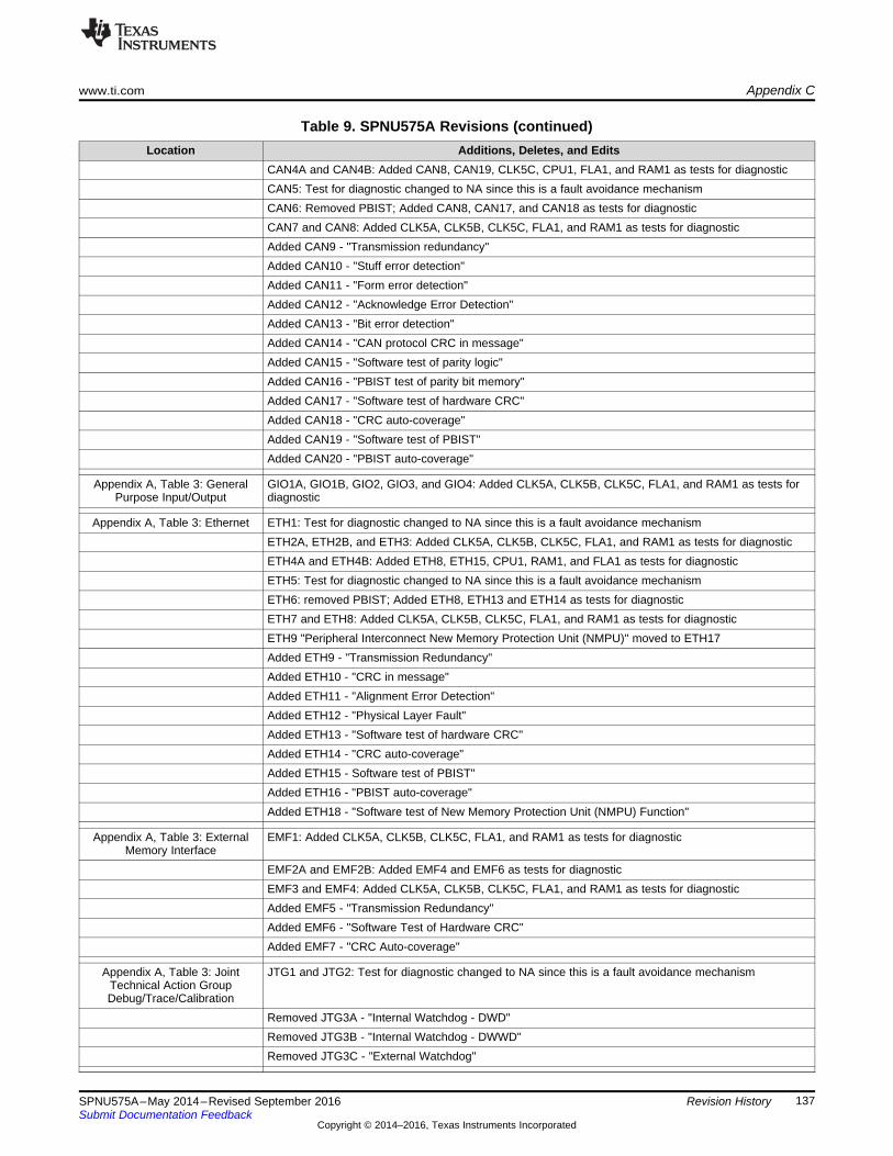
www.ti.com Appendix C
137SPNU575A–May 2014–Revised September 2016Submit Documentation Feedback
Copyright © 2014–2016, Texas Instruments Incorporated
Revision History
Table 9. SPNU575A Revisions (continued)Location Additions, Deletes, and Edits
CAN4A and CAN4B: Added CAN8, CAN19, CLK5C, CPU1, FLA1, and RAM1 as tests for diagnosticCAN5: Test for diagnostic changed to NA since this is a fault avoidance mechanismCAN6: Removed PBIST; Added CAN8, CAN17, and CAN18 as tests for diagnosticCAN7 and CAN8: Added CLK5A, CLK5B, CLK5C, FLA1, and RAM1 as tests for diagnosticAdded CAN9 - "Transmission redundancy"Added CAN10 - "Stuff error detection"Added CAN11 - "Form error detection"Added CAN12 - "Acknowledge Error Detection"Added CAN13 - "Bit error detection"Added CAN14 - "CAN protocol CRC in message"Added CAN15 - "Software test of parity logic"Added CAN16 - "PBIST test of parity bit memory"Added CAN17 - "Software test of hardware CRC"Added CAN18 - "CRC auto-coverage"Added CAN19 - "Software test of PBIST"Added CAN20 - "PBIST auto-coverage"
Appendix A, Table 3: GeneralPurpose Input/Output
GIO1A, GIO1B, GIO2, GIO3, and GIO4: Added CLK5A, CLK5B, CLK5C, FLA1, and RAM1 as tests fordiagnostic
Appendix A, Table 3: Ethernet ETH1: Test for diagnostic changed to NA since this is a fault avoidance mechanismETH2A, ETH2B, and ETH3: Added CLK5A, CLK5B, CLK5C, FLA1, and RAM1 as tests for diagnosticETH4A and ETH4B: Added ETH8, ETH15, CPU1, RAM1, and FLA1 as tests for diagnosticETH5: Test for diagnostic changed to NA since this is a fault avoidance mechanismETH6: removed PBIST; Added ETH8, ETH13 and ETH14 as tests for diagnosticETH7 and ETH8: Added CLK5A, CLK5B, CLK5C, FLA1, and RAM1 as tests for diagnosticETH9 "Peripheral Interconnect New Memory Protection Unit (NMPU)" moved to ETH17Added ETH9 - "Transmission Redundancy"Added ETH10 - "CRC in message"Added ETH11 - "Alignment Error Detection"Added ETH12 - "Physical Layer Fault"Added ETH13 - "Software test of hardware CRC"Added ETH14 - "CRC auto-coverage"Added ETH15 - Software test of PBIST"Added ETH16 - "PBIST auto-coverage"Added ETH18 - "Software test of New Memory Protection Unit (NMPU) Function"
Appendix A, Table 3: ExternalMemory Interface
EMF1: Added CLK5A, CLK5B, CLK5C, FLA1, and RAM1 as tests for diagnostic
EMF2A and EMF2B: Added EMF4 and EMF6 as tests for diagnosticEMF3 and EMF4: Added CLK5A, CLK5B, CLK5C, FLA1, and RAM1 as tests for diagnosticAdded EMF5 - "Transmission Redundancy"Added EMF6 - "Software Test of Hardware CRC"Added EMF7 - "CRC Auto-coverage"
Appendix A, Table 3: JointTechnical Action GroupDebug/Trace/Calibration
JTG1 and JTG2: Test for diagnostic changed to NA since this is a fault avoidance mechanism
Removed JTG3A - "Internal Watchdog - DWD"Removed JTG3B - "Internal Watchdog - DWWD"Removed JTG3C - "External Watchdog"
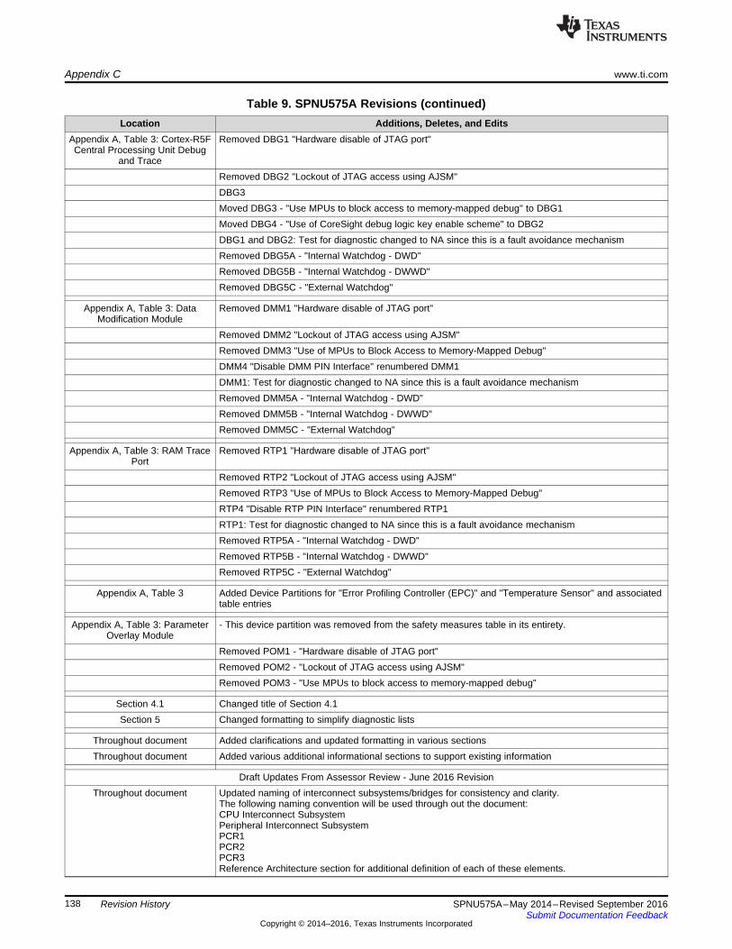
Appendix C www.ti.com
138 SPNU575A–May 2014–Revised September 2016Submit Documentation Feedback
Copyright © 2014–2016, Texas Instruments Incorporated
Revision History
Table 9. SPNU575A Revisions (continued)Location Additions, Deletes, and Edits
Appendix A, Table 3: Cortex-R5FCentral Processing Unit Debug
and Trace
Removed DBG1 "Hardware disable of JTAG port"
Removed DBG2 "Lockout of JTAG access using AJSM"DBG3Moved DBG3 - "Use MPUs to block access to memory-mapped debug" to DBG1Moved DBG4 - "Use of CoreSight debug logic key enable scheme" to DBG2DBG1 and DBG2: Test for diagnostic changed to NA since this is a fault avoidance mechanismRemoved DBG5A - "Internal Watchdog - DWD"Removed DBG5B - "Internal Watchdog - DWWD"Removed DBG5C - "External Watchdog"
Appendix A, Table 3: DataModification Module
Removed DMM1 "Hardware disable of JTAG port"
Removed DMM2 "Lockout of JTAG access using AJSM"Removed DMM3 "Use of MPUs to Block Access to Memory-Mapped Debug"DMM4 "Disable DMM PIN Interface" renumbered DMM1DMM1: Test for diagnostic changed to NA since this is a fault avoidance mechanismRemoved DMM5A - "Internal Watchdog - DWD"Removed DMM5B - "Internal Watchdog - DWWD"Removed DMM5C - "External Watchdog"
Appendix A, Table 3: RAM TracePort
Removed RTP1 "Hardware disable of JTAG port"
Removed RTP2 "Lockout of JTAG access using AJSM"Removed RTP3 "Use of MPUs to Block Access to Memory-Mapped Debug"RTP4 "Disable RTP PIN Interface" renumbered RTP1RTP1: Test for diagnostic changed to NA since this is a fault avoidance mechanismRemoved RTP5A - "Internal Watchdog - DWD"Removed RTP5B - "Internal Watchdog - DWWD"Removed RTP5C - "External Watchdog"
Appendix A, Table 3 Added Device Partitions for "Error Profiling Controller (EPC)" and "Temperature Sensor" and associatedtable entries
Appendix A, Table 3: ParameterOverlay Module
- This device partition was removed from the safety measures table in its entirety.
Removed POM1 - "Hardware disable of JTAG port"Removed POM2 - "Lockout of JTAG access using AJSM"Removed POM3 - "Use MPUs to block access to memory-mapped debug"
Section 4.1 Changed title of Section 4.1Section 5 Changed formatting to simplify diagnostic lists
Throughout document Added clarifications and updated formatting in various sectionsThroughout document Added various additional informational sections to support existing information
Draft Updates From Assessor Review - June 2016 RevisionThroughout document Updated naming of interconnect subsystems/bridges for consistency and clarity.
The following naming convention will be used through out the document:CPU Interconnect SubsystemPeripheral Interconnect SubsystemPCR1PCR2PCR3Reference Architecture section for additional definition of each of these elements.

www.ti.com Appendix C
139SPNU575A–May 2014–Revised September 2016Submit Documentation Feedback
Copyright © 2014–2016, Texas Instruments Incorporated
Revision History
Table 9. SPNU575A Revisions (continued)Location Additions, Deletes, and Edits
Appendix A, Table 3:Input/Output (I/O) Multiplexing
Module
IOM3: Added IOM5A and IOM5B as tests for diagnostics.
Section 6.18Section 7.121
Appendix A, Table 3:Input/Output (I/O) MultiplexingModule
Updated the Safety Feature/Diagnostic References/Names to the Boot Time and Periodic Software Testof Function Using I/O Loopback by adding "Including Error Test" in the IOMM list of Safety Mechanisms.
Section 7.121 Updated description of the safety diagnostic to include test of error trapping as a tested feature of theIOMM module such that it can serve as a test for diagnostic for the Error Trapping Safety Diagnosticwithin the module.
Draft Updates From Assessor Review - September 2016 RevisionThroughout Updates to Safety Feature/Diagnostic names to better align with the FMEDA document.
Updated link to correctly point to the ARM Cortex-R5F TRM located on the ARM websitehttp://infocenter.arm.com/help/topic/com.arm.doc.ddi0460d/index.html
Figure 5 Removed the block "Network Peripheral" from the diagram.Section 6.41 Removes Online Profiling Using PMU, Illegal Operation and Instruction Trapping from the list of Safety
Features/Diagnostics. Moved Flash ECC into Safety Features/Diagnostic list. Duplicated LockstepCompare, Internal and External Watchdogs, and Flash and RAM ECC diagnostics under latent faultdetection as these are also tests for diagnostics for the temperature sensor feature.
Appendix A, Table 3: PrimarySRAM Element
RAM20 test for diagnostics, usage, Test Execution Time, Action on detected Fault, Error Reporting Timeupdated to reflect a fault avoidance mechanism rather than a Diagnostic.
Appendix A, Table 3: High-EndTimer (N2HET) Including HETTransfer Unit (HTU) Element
HET21A and HET21B Possible Tests for Diagnostics updated to remove CLK5A, CLK5B, CLK5C,CPU1, FLA1 and RAM1 and replace all of these with LBIST Auto-Coverage (HET22 newly defined).
Appendix A, Table 3: High-EndTimer (N2HET) Including HETTransfer Unit (HTU) Element
Added HEt22 LBIST Auto-Coverage
Appendix A, Table 3: SerialCommunication Interface (SCI)Element
Updated SCI9 Possible Tests for Diagnostics to SCI2 Information Redundancy Techniques
Appendix A, Table 3: ControllerArea Network (DCAN) Element
CAN3 - Added CAN2 Information Redundancy Including End to End Safing as Possible Test forDiagnostic

IMPORTANT NOTICE
Texas Instruments Incorporated and its subsidiaries (TI) reserve the right to make corrections, enhancements, improvements and otherchanges to its semiconductor products and services per JESD46, latest issue, and to discontinue any product or service per JESD48, latestissue. Buyers should obtain the latest relevant information before placing orders and should verify that such information is current andcomplete. All semiconductor products (also referred to herein as “components”) are sold subject to TI’s terms and conditions of salesupplied at the time of order acknowledgment.TI warrants performance of its components to the specifications applicable at the time of sale, in accordance with the warranty in TI’s termsand conditions of sale of semiconductor products. Testing and other quality control techniques are used to the extent TI deems necessaryto support this warranty. Except where mandated by applicable law, testing of all parameters of each component is not necessarilyperformed.TI assumes no liability for applications assistance or the design of Buyers’ products. Buyers are responsible for their products andapplications using TI components. To minimize the risks associated with Buyers’ products and applications, Buyers should provideadequate design and operating safeguards.TI does not warrant or represent that any license, either express or implied, is granted under any patent right, copyright, mask work right, orother intellectual property right relating to any combination, machine, or process in which TI components or services are used. Informationpublished by TI regarding third-party products or services does not constitute a license to use such products or services or a warranty orendorsement thereof. Use of such information may require a license from a third party under the patents or other intellectual property of thethird party, or a license from TI under the patents or other intellectual property of TI.Reproduction of significant portions of TI information in TI data books or data sheets is permissible only if reproduction is without alterationand is accompanied by all associated warranties, conditions, limitations, and notices. TI is not responsible or liable for such altereddocumentation. Information of third parties may be subject to additional restrictions.Resale of TI components or services with statements different from or beyond the parameters stated by TI for that component or servicevoids all express and any implied warranties for the associated TI component or service and is an unfair and deceptive business practice.TI is not responsible or liable for any such statements.Buyer acknowledges and agrees that it is solely responsible for compliance with all legal, regulatory and safety-related requirementsconcerning its products, and any use of TI components in its applications, notwithstanding any applications-related information or supportthat may be provided by TI. Buyer represents and agrees that it has all the necessary expertise to create and implement safeguards whichanticipate dangerous consequences of failures, monitor failures and their consequences, lessen the likelihood of failures that might causeharm and take appropriate remedial actions. Buyer will fully indemnify TI and its representatives against any damages arising out of the useof any TI components in safety-critical applications.In some cases, TI components may be promoted specifically to facilitate safety-related applications. With such components, TI’s goal is tohelp enable customers to design and create their own end-product solutions that meet applicable functional safety standards andrequirements. Nonetheless, such components are subject to these terms.No TI components are authorized for use in FDA Class III (or similar life-critical medical equipment) unless authorized officers of the partieshave executed a special agreement specifically governing such use.Only those TI components which TI has specifically designated as military grade or “enhanced plastic” are designed and intended for use inmilitary/aerospace applications or environments. Buyer acknowledges and agrees that any military or aerospace use of TI componentswhich have not been so designated is solely at the Buyer's risk, and that Buyer is solely responsible for compliance with all legal andregulatory requirements in connection with such use.TI has specifically designated certain components as meeting ISO/TS16949 requirements, mainly for automotive use. In any case of use ofnon-designated products, TI will not be responsible for any failure to meet ISO/TS16949.
Products ApplicationsAudio www.ti.com/audio Automotive and Transportation www.ti.com/automotiveAmplifiers amplifier.ti.com Communications and Telecom www.ti.com/communicationsData Converters dataconverter.ti.com Computers and Peripherals www.ti.com/computersDLP® Products www.dlp.com Consumer Electronics www.ti.com/consumer-appsDSP dsp.ti.com Energy and Lighting www.ti.com/energyClocks and Timers www.ti.com/clocks Industrial www.ti.com/industrialInterface interface.ti.com Medical www.ti.com/medicalLogic logic.ti.com Security www.ti.com/securityPower Mgmt power.ti.com Space, Avionics and Defense www.ti.com/space-avionics-defenseMicrocontrollers microcontroller.ti.com Video and Imaging www.ti.com/videoRFID www.ti-rfid.comOMAP Applications Processors www.ti.com/omap TI E2E Community e2e.ti.comWireless Connectivity www.ti.com/wirelessconnectivity
Mailing Address: Texas Instruments, Post Office Box 655303, Dallas, Texas 75265Copyright © 2016, Texas Instruments Incorporated