media redundancy protocol configuration guide for ie 2000 ... ·...
TRANSCRIPT

Media Redundancy Protocol Configuration Guide for IE 2000, IE 4000,IE 4010, and IE 5000 Switches
Configuring MRP 2

Revised: March 28, 2019
Configuring MRPThis document describes how to configureMedia Redundancy Protocol (MRP) on the Cisco Industrial Ethernet 2000 Series Switches(IE 2000), Cisco Industrial Ethernet 4000 Series Switches (IE 4000), Cisco Industrial Ethernet 4010 Series Switches (IE 4010), andCisco Industrial Ethernet 5000 Series Switches (IE 5000).
Information About MRPMRP, defined in International Electrotechnical Commission (IEC) standard 62439-2, provides fast convergence in a ring networktopology for Industrial Automation networks. MRP Media Redundancy Manager (MRM) defines its maximum recovery times for aring in the following range: 10 ms, 30 ms, 200 ms and 500 ms.
The term switch refers to the IE 2000, IE 4000, IE 4010, or IE 5000 unless otherwise noted.Note
The default maximum recovery time on the Cisco IE switch is 200 ms for a ring composed of up to 50 nodes. You can configurethe switch to use the 500 ms recovery time profile as described in Configuring MRP Manager, on page 17.
Note
MRP operates at the MAC layer and is commonly used in conjunction with the PROFINET standard for industrial networking inmanufacturing.
MRP Modes
We support two modes of MRP on the switch; however, only one mode can be enabled to operate on the switch at any given time:
• PROFINETMRPmode—Deployed in a PROFINET environment, the switch is added andmanaged by Siemens Totally IntegratedAutomation (TIA) Framework. This is the default MRP mode if the MRP manager or client license is activated through the webinterface or command line. For more information, see Re-enabling PROFINET MRP, on page 22.
When managing the switch with TIA, do not use the CLI or Web Device Manager to configure MRP.Note
• MRPCommand-line interface (CLI) mode—This mode is managed by the Cisco IOS CLI andWebDeviceManager, a web-baseduser interface (UI). For more information, see Configuring MRP CLI Mode, on page 16 and the Device Manager online help.
When managing the switch in MRP CLI mode, you cannot download the MRP configuration from SiemensSTEP7/TIA.
Note
2

Protocol Operation
In an MRP ring, the MRM serves as the ring manager, while the Media Redundancy Clients (MRCs) act as member nodes of thering. Each node (MRM or MRC) has a pair of ports to participate in the ring. The MRM initiates and controls the ring topology toreact to network faults by sending control frames on one ring port over the ring and receiving them from the ring over its other ringport, and conversely in the other direction. An MRC reacts to received reconfiguration frames from the MRM and can detect andsignal link changes on its ring ports.
On IE 4000, IE 4010, and IE 5000 switches, certain nodes or all nodes in the ring can also be configured to start as aMedia RedundancyAutomanager (MRA). MRAs select one MRM among each other by using a voting protocol and a configured priority value. Theremaining MRAs transition to the MRC role. For more information, see Media Redundancy Automanager (MRA), on page 4.
All MRM and MRC ring ports support the following states:
• Disabled—ring ports drop all received frames.
• Blocked—ring ports drop all received frames except MRP control frames and some standard frames, for example, LLDP.
• Forwarding—ring ports forward all received frames.
• Not Connected—the link is physically down or disconnected. (This state differs from the Disabled state, in which the MRP Portis manually disabled through software.)
During normal operation, the network operates in the Ring-Closed state (see figure below). To prevent a loop, one of the MRM ringports is blocked, while the other port is forwarding. Most of the time, both ring ports of all MRCs are in the forwarding state. Withthis loop avoidance, the physical ring topology becomes a logical stub topology.
In the figure, note the following details about the two rings, left and right:
• Left Ring: The connection (small blue square, top) on the MRM is in a blocked state (as shown by the two parallel lines) becauseno ports are disconnected.
• Right Ring: Two MRC connections (left and center small white squares) are in the disabled state because the link between themis broken, as marked by a red “x”.
3

Figure 1: MRP RIng States
If a network failure occurs:
• The network shifts into the Ring-Open state.
• In the case of failure of a link connecting two MRCs, both ring ports of the MRM change to the forwarding state, the MRCsadjacent to the failure have a disabled and a forwarding ring port, and the other MRCs have both ring ports forwarding.
In the Ring-Open state, the network logical topology becomes a stub.
Layer 2 Ethernet frames will be lost during the time required for the transition between these two ring states. The MRP protocoldefines the procedures to automatically manage the switchover to minimize the switchover time. A recovery time profile, composedof various parameters, drives the MRP topology convergence performance. The 200 ms profile supports a maximum recovery timeof 200 ms. The 500 ms profile supports a maximum recovery time of 500 ms.
MRP uses three types of control frames:
• To monitor the ring status, MRM regularly sends test frames on both ring ports.
• When MRM detects failure or recovery, it sends TopoChange frames on both ring ports.
• WhenMRC detects failure or recovery on a local port, it sends LinkChange subtype frames, Linkdown and Linkup, to theMRM.
Media Redundancy Automanager (MRA)
This section applies to IE 4000, IE 4010, and IE 5000 switches only. MRA can be activated through the CLI or throughPROFINET.
Note
4

If configured to start as a Media Redundancy Automanager (MRA), the node or nodes select an MRM using a voting protocol andconfigured priority value. The remaining MRAs transition to the MRC role. All nodes must be configured as MRA or MRC. Amanually configured MRM and MRA in the same ring is not supported.
The MRA role is not an operational MRP role like MRM or MRC. It is only an administrative, temporary role at device startup, anda node must transition to the MRM role or the MRC role after startup and the MRM is selected though the manager voting process.
MRA functions as follows:
1. At power on, all MRAs begin the manager voting process. Each MRA begins to send MRP_Test frames on both ring ports. TheMRP_Test frame contains the MRA's priority value. The remote manager's priority value contained in the received MRP_Testframes are compared with the MRA's own priority. If its own priority is higher than the received priority, the MRA sends anegative test manager acknowledgement (MRP_TestMgrNAck) frame, along with the remote manager's MAC address.
2. If the receiving MRA receives an MRP_TestMgrNAck with its own MAC address, the receiving MRA initiates the transitioninto the client (MRC) role.
3. The MRP_TestPropagate frame informs other MRA devices in the client role about the role change and the new higher prioritymanager. The clients receiving this frame update their higher priority manager information accordingly. This ensures that clientsremain in the client role if the monitored higher priority manager role changes.
MRP Licensing
Use of MRP on IE switches is based on Right To Use (RTU) licenses. MRP is supported on all license levels, including Lan Lite,Lan Base, IP Lite, and IP Service. You can transfer your permanent MRP license to a new switch using the SD card, as described inLicense Portability (ZTD), on page 6.
MRP license product IDs (PIDs) for the IE 2000, IE 4000, IE 4010, and IE 5000 switches are listed in the following table. See FeatureHistory, on page 26 for a complete list of MRP feature support by platform and release.
Table 1: Cisco IE 2000, IE 4000, IE 4010, and IE 5000 MRP License Product IDs
Platform andMinimumRequired ReleaseDescriptionLicense PID
IE 2000: 15.2(4)EA
IE 4000: 15.2(4)EA1
IE 5000: 15.2(5)E1
IE 4010: 15.2(5)E2, 15.2(7)E
MRP ring manager license.
This license enables the MRA administrative role on the IE4000, IE 4010, and IE 5000. The same license enablesMRMfor the IE 2000.
LIC-MRP-MANAGER=
IE 2000 : 15.2(4)EA
IE 4000: 15.2(4)EA1
IE 5000: 15.2(5)E1
IE 4010: 15.2(5)E2
MRP ring client license.LIC-MRP-Client=
Each of the MRP licenses listed above is available as an evaluation license and a permanent license. When an MRP license expiresor is deactivated, the MRP ring configurations remain until the next reboot. To activate MRP licenses, see Activating the MRPLicense, on page 9.
5

On the IE 4000, IE 4010, and IE 5000, you can configure up to three rings with either the MRP manager license or the MRPclient license. With the MRP manager license, the switch can be configured as either automanager or client. With the MRPclient license, the switch can be configured only as client.
On the IE 2000, you can configure up to three managers (one manager per ring) with the manager license, or you can configureone client with the MRP client license. Multiple rings are supported only with the MRP manager license.
Note
License Portability (ZTD)
MRP licensing includes a feature to facilitate Zero Touch Deployment (ZTD). If a switch with an MRP license fails and you mustreplace the switch with a brand new one, you can transfer the MRP license from the failed switch to the new switch by using the SDcard to transfer the license. MRP license portability is turned on by default, and there is no configuration required for this feature.
Requirements for MRP license portability are as follows:
• MRP Right-to-Use license portability supports only permanent licenses, not evaluation licenses.
• The Zero touch license transfer works only if the switch is in factory default mode. If the replacement switch has been previouslyused, reset the switch to factory defaults as described in “Running Express Setup” in the Cisco IE 2000 Switch HardwareInstallation Guide, Cisco IE 4000 Switch Hardware Installation Guide, or Cisco IE 5000 Hardened Aggregator HardwareInstallation Guide
• License Portability is supported on the IE 2000, IE 4000, IE 4010, and IE 5000.
• The switches must have an SD card.
• The source switch for the license transfer must have been booted up with the SD card before the transfer.
• License Portability is not backward compatitible with Cisco IOS releases prior to 15.2(5)E2:
• If you configured the multi-manager license (in a release prior to prior to 15.2(5)E2), you should deactivate it beforeupgrading to 15.2(5)E2.
• If you configure the manager license using the 15.2(5)E2 image and then downgrade to an image prior to 15.2(5)E2, themanager license will be retained but not the multi-manager license.
To transfer the license, insert the SD card into the target switch and reload the switch. After the first reload, MRP license informationis consistent with the license information on the old switch. Any latter modification (activation or deactivation) of permanent licensesis synced to the SD card immediately. This ensures that the SD card license file preserves the latest MRP license information.
Multiple MRP Rings
In an Industrial Ethernet network, an MRP ring in a cell/area is a sub-ring of the access layer. Depending on the MRP license andplatform, you can connect multiple MRP rings, which you can then aggregate into the distribution layer.
• On the IE 4000, IE 4010, and IE 5000, you can connect up to three MRP rings with the mrp-manager or mrp-client license (thecommon node can be auto-manager or client).
• On the IE 2000, you can connect up to three MRP rings with the mrp-manager license. All three rings must be configured asmanager.
The three MRP rings must have the same VLAN ID, with a unique MRP Domain ID in each ring. All three rings are controlled bythe same MRP manager. Multiple MRP rings can be managed only by Cisco Web Device Manager or CLI, not Siemens STEP7/TIA.See Configuring MRP CLI Mode, on page 16 for more information.
6

MRP-STP Interoperability
MRP works with Spanning Tree Protocol (STP) to prevent unwanted broadcast loops in the event that a user accidentally connectsa device that does not participate in the MRP ring. In a network operating with MRP and STP, spanning tree BPDUs are not sent onMRP-enabled ports. If ports are unconfigured from an MRP ring, then the ports are added to the spanning tree.
MRP-STP interoperability is supported for both PROFINET MRP mode and MRP CLI mode, and functions without additional CLIconfiguration.
Prerequisites• MRPManager and MRP Client licenses are Right-to-Use trust model licenses. You need to purchase the licenses through CiscoCommerce (https://cisco-apps.cisco.com/cisco/psn/commerce).
• TheMRP protocol is supported on Lan Lite, Lan Base, Enhanced Lan Base, and IPLite for IE 2000, and Lan Base and IP Servicesfor IE 4010, IE 4000, and IE 5000.
• Because MRP is deployed in a physical Ring topology, before configuring the MRP feature, it is advised to leave one physicalconnection between two nodes in each ring open by either issuing a shut command on the connecting interfaces or physicallyremoving the cable to avoid any network storms. After you have properly configured all MRCs and MRMs (or MRAs on IE4000, IE 4010, and IE 5000), issue a no shut command on the port or re-connect the cable between the nodes.
• Activate the MRP License before you configure the MRP protocol. See Activating the MRP License, on page 9.
• Determine the MRP configuration on the switch: MRP manager (or MRA on IE 4000, IE 4010, and IE 5000) or client.
• When the network is managed by SIMATIC TIA or STEP7, ensure that the basic PROFINET connection is on.
• The MRP default VLAN is 1. To use a non-default VLAN, you must configure the PROFINET VLAN ID before assigning itto the MRP configuration.
Guidelines and Limitations• By default, PROFINET MRP is enabled. You can configure MRP, including the MRP role, using the Cisco switch CLI onlyafter you disable the PROFINET MRP function using the Cisco switch CLI.
When PROFINET MRP is enabled, use STEP7 and TIA to configure MRP, including the MRP role.
• MRP licensing must be activated using the Cisco switch CLI.
• With the MRP manager license, you can configure up to three rings in the same VLAN on the device (each MRP instance canbe manager or client), with a manager instance for each ring. Support for multiple MRP rings is available only through the CLIor Web Device Manager tool.
• The switch supports up to 50 MRCs per ring.
• MRP cannot run on the same interface (port) as Resilient Ethernet Protocol (REP), Spanning Tree Protocol (STP), Flex Links,or Dot1x.
• STP does not run on MRP segments. MRP interfaces drop all STP BPDUs.
• For access ports, you must specifically configure switchport mode access and switchport access vlan x commands in the MRPinterface.
• MRP interfaces come up in a forwarding state and remain in a forwarding state until notified that it is safe to block. The MRPring state changes to Ring-Closed.
7

• MRP ports cannot be configured as any of these port types: SPAN destination port, Private VLAN port, or Tunnel port.Additionally, when operating in PROFINET mode, you cannot configure MRP ports as Trunk ports.
• MRP is not supported on EtherChannels or on an individual port that belongs to an EtherChannel.
• We recommend that you configure MRP nodes in either an all Fast Ethernet or all Gigabit Ethernet topology.
• On the IE 5000, MRP is supported on downlink ports only. The system displays an error message if you attempt to configureMRP on uplink ports.
• Over-subscription or congestion will cause MRP control frames to drop. This behavior is similar to STP BPDUs. On the IE2000, configuringmls qos trust cos, mls qos cos 7 on all the MRP ports might slightly improve performance. Note that youmust also enable QoS globally for these commands to take effect. Once congestion is resolved, MRP resumes normal operation.
IE 4000, IE 4010, and IE 5000 switches can handle congestion without dropping MRP control frames.
• Each MRP ring can have one MRP VLAN.
PROFINET MRP Mode only
• You can configure only one MRP ring in PROFINET MRP mode.
The number of mrp rings displayed in the show profinet status command output indicates license capability, notPROFINET configuration capability.
Note
• In PROFINET MRP, which is managed by STEP7 and TIA, only Layer 2 access ports are supported because PROFINET doesnot have the concept of VLAN tagging.
• The 10ms and 30ms profiles are not supported in PROFINET MRP mode.
• When using PROFINET MRP mode, we recommend setting the LLDP timer to 5 ms or 10 ms to ensure PROFINET can seeneighbor devices and to avoid a Siemens PLC timeout.
• InterVLAN routing capability is required for the management VLAN to communicate with the PROFINET MRP VLAN.InterVLAN routing is supported on all software licenses except Lan Lite on the IE 2000.
• When a new pluggable module GSD file is installed in TIA/ STEP7, you must recreate the project in TIA/Step7. The existingproject, which was created using the old GSD file, will display an error when you attempt to select the new GSD file for thesame device. This occurs because the combo ports in the pluggable module SKUs were previously defined as fixed ports.
MRP CLI Mode Only
• MRP CLI mode is supported on both Layer 2 access ports and trunk ports.
• After using the CLI to configure the MRP ring, you must attach the MRP ring to a pair of ports that support MRP.
• Both MRP ports must have the same interface mode (access or trunk).
• To change an existing MRP ring's configuration (mode), or to change the interface mode of the ring ports between access andtrunk, you must first delete the ring and then recreate it with the new configuration.
• When both MRP ports are in access mode, the access VLANs should match. If the configured MRP VLAN does not match theports' access VLAN, the MRP VLAN is automatically changed to the MRP ports’ access VLAN.
8

• In an MRP ring with two access ports, if the ports do not belong to the same access VLAN when you create the MRP ring oryou change the access VLAN for only one of the ports after the MRP ring is created, the MRP ring operation is suspended anda message similar to the following is displayed:
ERROR% The ring 1 ports don't belong to the same access VLAN. The MRP ring will not function until theissue has been fixed
Resolve the issue by configuring the access VLAN to be the same for the two ring ports.
• The standard profiles 200 ms and 500 ms are supported. The 10 ms and 30 ms profiles are not supported.
Media Redundancy Automanager (MRA)
• MRA is supported on the IE 4000, IE 4010, and IE 5000 only.
• The MRA role and the static MRM role are not supported in the same ring. For MRA to work, there can be no MRM devicesthat are not participating in the election process. When configured for MRA, all devices in the ring that support the managerrole must be set to MRP-role “Manager (Auto)” or remain in the MRP-role “Client”; however, at least one device in the ringmust be set to either the MRP-role “Manager (Auto)” or “Manager”.
• MRA sends NACK and PROP using MRP_IECOUI defined in specification IEC62439. Packet formats are defined accordingly.
Default Settings• MRM and MRC licenses are disabled by default.
• PROFINET MRP is enabled by default when MRM or MRC licenses are enabled.
• MRP is disabled by default.
• The default VLAN is 1.
• Create the non-default VLAN before you assign it to MRP ring 1.
Activating the MRP LicenseYou must activate the MRP License before you configure the MRP feature on the switch.
MRP Manager and Client manager licenses are Right-to-Use trust model licenses. You need to purchase the licenses throughCisco Commerce (https://cisco-apps.cisco.com/cisco/psn/commerce). See Table 1: Cisco IE 2000, IE 4000, IE 4010, and IE5000 MRP License Product IDs, on page 5 for the list of license PIDs.
Note
You can activate the license by using the Cisco IOS command-line interface (CLI).
To activate the license on your switch, enter one of the following commands at the Privileged EXEC mode:
Switch# license right-to-use activate mrp-clientSwitch# license right-to-use activate mrp-manager
After entering the above command you will see terms for the license. Answer yes to accept.Note
9

To view details on the activated license, enter the following command at the Privileged EXEC mode:
Switch# show licenseIndex 1 Feature: lanbase
Period left: Life timeLicense Type: PermanentLicense State: Active, In UseLicense Priority: MediumLicense Count: Non-Counted
... <abbreviated display>Index 5 Feature: mrp-manager
Period left: 8 weeks 4 daysLicense Type: EvaluationLicense State: Active, Not in Use, EULA not acceptedLicense Priority: NoneLicense Count: 1/0/0 (Active/In-use/Violation)
Index 6 Feature: mrp-clientPeriod left: Life timeLicense Type: PermanentRightToUseLicense State: Active, In UseLicense Priority: HighLicense Count: 1/1/0 (Active/In-use/Violation
After you activate the MRP license for either mrp-client or mrp-manager and then enable MRP using the commandmrp ring1, the command show mrp ring 1 shows the MRP mode as Client by default. After you complete the MRP configuration,show mrp ring 1 will display the correct mode for your license.
Note
Configuring PROFINET MRP Mode Using TIA 13 or STEP7After Activating the MRP License, on page 9, you can push PROFINET MRP configuration to the Cisco switch using SiemensTIA or STEP7. PROFINET MRP is enabled by default on the switch when MRM or MRC licenses are enabled.
Do not use the CLI to configure or modify the switch configuration when PROFINET and TIA are in use. This includessetting the MRC or MRM role. MRP CLI mode and PROFINET MRP modes are mutually exclusive.
Note
If the Cisco switch is connected to the PROFINET PLC, the output of show profinet status | include Connected is Yes. Ifthe output of show profinet status | include Connected is No, then the switch is not connected to the PROFINET PLC.
Note
Installing the PROFINET GSD File
ThePROFINETMRPGSD file (Cisco_IE2000_GSD.zip, Cisco_IE4000_GSD.zip, Cisco_IE4010_GSD.zip, or Cisco_IE5000_GSD.zip)is bundled within the Cisco IOS release. After you unzip the image from your PC, you can manually copy or transport the GSD XMLfile to a TIA 13 PC location and upload it to the GSD directory.
We recommend that you always use the latest released GSD file. To ensure that you always have the correct GSD file, always updatethe Cisco IOS software version on the switch with the .tar file. The .tar file has the correct GSD version for the Cisco IOS softwareversion.
10

If you have a GSDXML file installed in TIA 13 or STEP 7 that is older than the version bundled with the Cisco IOS software,we recommend that you remove the older file to prevent any possible incompatibilities.
Caution
For supported SFP transceivers by platform, refer to the IE 2000, IE 4000, IE 4010, and IE 5000 data sheets.Note
See Feature History, on page 26 for minimum required Cisco IOS release.
Bringing Up PROFINET MRP
Prerequisites
We recommend allowing a MRP Ethernet port, disconnected from the ring (open ring), to discover all the neighbor devices using theLLDP protocol, before pushing the PROFINET MRP to the network. This approach avoids any unnecessary flooding should therebe any issues.
Procedure
Step 1 (Optional) Verify that the LLDP protocol discovers all neighbors correctly by entering show lldp neighbor.Step 2 Verify that all of the MRP licenses are active on the switch.Step 3 Ensure PROFINET status shows as connected.Step 4 Inspect the output of profinet mrp ring 1 to confirm that the MRP ports connected correctly and report:
• One MRM port in blocked mode
• All other (balance of) MRM ports in forwarding mode
Before making a MRP device role change (such as MRP client to MRP manager or MRP manager to MRPclient), make sure that the MRP ring is OPEN.
Note
Managing PROFINET Using Simatic Step 7 or TIA 13 Portal
This section provides an overview of key screens within the TIA portal (Siemens Simatic STEP7, version 13). It does not provideany configuration details. For details on using the TIA portal, refer to the Siemens Simatic STEP7 user documentation.
MRP automanager in PROFINET mode (on the IE 4000, IE 4010, and IE 5000) is supported only in TIA V14. It is notbackward compatible to TIA V13.
Note
11

Figure 2: PROFINET Device Discovery (DCP) Window Before Configuring MRP
12

Figure 3: Define PROFINET MRP Manager and MRP domain
13

Figure 4: Define PROFINET MRP Client and MRP Domain
14

Figure 5: Define PROFINET MRP Interfaces
15
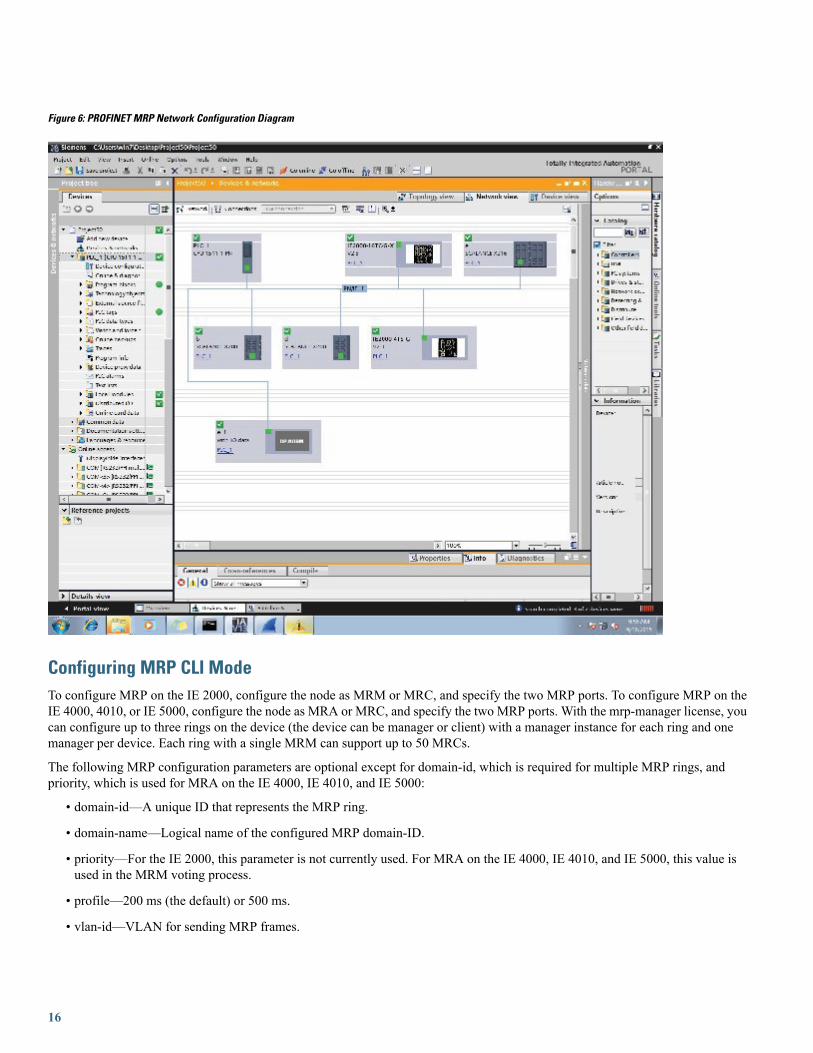
Figure 6: PROFINET MRP Network Configuration Diagram
Configuring MRP CLI ModeTo configure MRP on the IE 2000, configure the node as MRM or MRC, and specify the two MRP ports. To configure MRP on theIE 4000, 4010, or IE 5000, configure the node as MRA or MRC, and specify the two MRP ports. With the mrp-manager license, youcan configure up to three rings on the device (the device can be manager or client) with a manager instance for each ring and onemanager per device. Each ring with a single MRM can support up to 50 MRCs.
The following MRP configuration parameters are optional except for domain-id, which is required for multiple MRP rings, andpriority, which is used for MRA on the IE 4000, IE 4010, and IE 5000:
• domain-id—A unique ID that represents the MRP ring.
• domain-name—Logical name of the configured MRP domain-ID.
• priority—For the IE 2000, this parameter is not currently used. For MRA on the IE 4000, IE 4010, and IE 5000, this value isused in the MRM voting process.
• profile—200 ms (the default) or 500 ms.
• vlan-id—VLAN for sending MRP frames.
16
• default—In global MRP configuration, sets the mode to client.
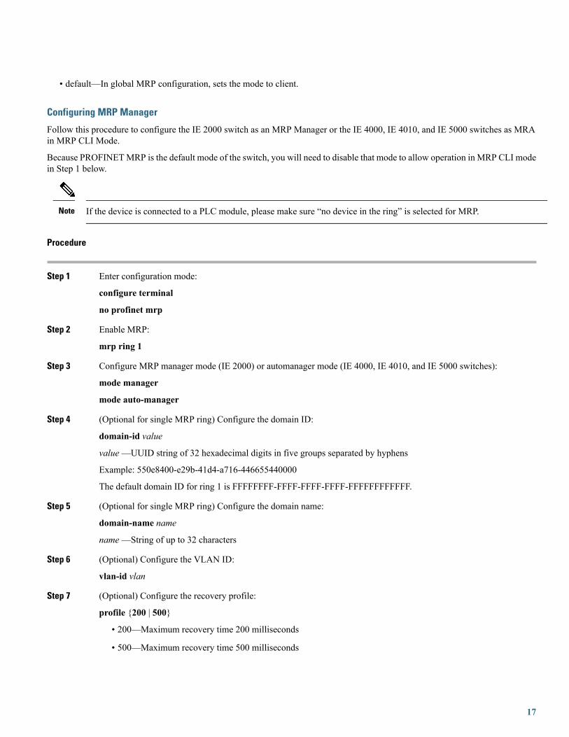
Configuring MRP Manager
Follow this procedure to configure the IE 2000 switch as an MRP Manager or the IE 4000, IE 4010, and IE 5000 switches as MRAin MRP CLI Mode.
Because PROFINETMRP is the default mode of the switch, you will need to disable that mode to allow operation in MRP CLI modein Step 1 below.
If the device is connected to a PLC module, please make sure “no device in the ring” is selected for MRP.Note
Procedure
Step 1 Enter configuration mode:
configure terminal
no profinet mrp
Step 2 Enable MRP:
mrp ring 1
Step 3 Configure MRP manager mode (IE 2000) or automanager mode (IE 4000, IE 4010, and IE 5000 switches):
mode manager
mode auto-manager
Step 4 (Optional for single MRP ring) Configure the domain ID:
domain-id value
value—UUID string of 32 hexadecimal digits in five groups separated by hyphens
Example: 550e8400-e29b-41d4-a716-446655440000
The default domain ID for ring 1 is FFFFFFFF-FFFF-FFFF-FFFF-FFFFFFFFFFFF.
Step 5 (Optional for single MRP ring) Configure the domain name:
domain-name name
name—String of up to 32 characters
Step 6 (Optional) Configure the VLAN ID:
vlan-id vlan
Step 7 (Optional) Configure the recovery profile:
profile {200 | 500}
• 200—Maximum recovery time 200 milliseconds
• 500—Maximum recovery time 500 milliseconds
17

Step 8 On the IE 4000, IE 4010, and IE 5000, configure the MRA priority:
priority value
value—Range: <36864 – 61440>, lowest: 65535.
The default priority is 40960.
Step 9 Return to privileged EXEC mode:
end
Step 10 Enter configuration mode:
configure terminal
Step 11 Specify the ID of the port that serves as the first ring port:
interface port
Step 12 Configure the interface mode:
switchport mode { access | trunk }
You must specify switchport mode access when configuring MRP in access mode.Note
Step 13 Associate the interface to the MRP ring:
mrp ring 1
Step 14 Return to global configuration mode:
exit
Step 15 Specify the ID of the port that serves as second ring port:
interface port
Step 16 Configure the interface mode:
switchport mode { access | trunk }
You must specify switchport mode access at this step when configuring MRP in access mode.Note
Step 17 Associate the interface to the MRP ring:
mrp ring 1
Step 18 Return to privileged EXEC mode:
end
Step 19 (For multiple rings) Repeat step 2 through 15 for each additional ring:
• Assign ring number 2 for the second ring.
• Assign a unique domain ID for Ring 2. The default domain ID for ring 2 isFFFFFFFF-FFFF-FFFF-FFFF-FFFFFFFFFFFE.
• Assign ring number 3 for the third ring.
• Assign a unique domain ID for Ring 3. The default domain ID for ring 3 isFFFFFFFF-FFFF-FFFF-FFFF-FFFFFFFFFFFD.
18

Each ring should have its own domain ID. No two rings share the same domain ID.Note
Example
The following example shows configuring MRP automanager:
Switch#configure terminalSwitch# no profinet mrpEnter configuration commands, one per line. End with CNTL/Z.Switch(config)#mrp ring 1Switch(config-mrp)#mode auto-managerSwitch(config-mrp-auto-manager)#domain-id FFFFFFFF-FFFF-FFFF-FFFF-FFFFFFFFFFFFSwitch(config-mrp-auto-manager)#priority 40960Switch(config-mrp-auto-manager)#endSwitch#configure terminalEnter configuration commands, one per line. End with CNTL/Z.Switch(config)#GigabitEthernet1/2Switch(config-if)#switchport mode trunkSwitch(config-if)#mrp ring 1WARNING% Enabling MRP automatically set STP FORWARDING. It is recommended to shutdown all interfaces which arenot currently in use to prevent potential bridging loops.Switch(config-if)#exitSwitch(config)#GigabitEthernet1/1Switch(config-if)#switchport mode trunkSwitch(config-if)#mrp ring 1WARNING% Enabling MRP automatically set STP FORWARDING. It is recommended to shutdown all interfaces which arenot currently in use to prevent potential bridging loops.Switch(config-if)#exitSwitch(config-if)#end
Switch# show mrp ring 1MRP ring 1
Profile : 200 msMode : Auto-ManagerPriority : 40960Operational Mode: ClientFrom : CLILicense : ActiveBest Manager :MAC Address : 00:78:88:5E:03:81Priority : 36864
Network Topology: RingNetwork Status : OPENPort1: Port2:MAC Address :84:B8:02:ED:E8:02 MAC Address :84:B8:02:ED:E8:01Interface :GigabitEthernet1/2 Interface :GigabitEthernet1/1Status :Forwarding Status :Forwarding
VLAN ID : 1Domain Name : Cisco MRP Ring 1Domain ID : FFFFFFFF-FFFF-FFFF-FFFF-FFFFFFFFFFFF
Topology Change Request Interval : 10msTopology Change Repeat Count : 3Short Test Frame Interval : 10msDefault Test Frame Interval : 20msTest Monitoring Interval Count : 3
19

Test Monitoring Extended Interval Count : N/ASwitch#show mrp ports
Ring ID : 1PortName Status--------------------------------------GigabitEthernet1/2 ForwardingGigabitEthernet1/1 Forwarding
Configuring MRP Client
Follow this procedure to configure the switch as an MRP Client.
Procedure
Step 1 Enter configuration mode:
configure terminal
Step 2 Enable MRP:
mrp ring 1
Step 3 Configure MRP client mode (if you do not specify the mode, client mode is the default):
mode client
Step 4 (Optional) Configure the domain ID matching the one configured for this ring on MRM (Step 4 in Configuring MRPManager, on page 17):
domain-id value
value—UUID string of 32 hexadecimal digits in five groups separated by hyphens
Example: 550e8400-e29b-41d4-a716-446655440000
The default domain ID for ring 1 is FFFFFFFF-FFFF-FFFF-FFFF-FFFFFFFFFFFF.
Step 5 Return to privileged EXEC mode:
end
Step 6 Enter configuration mode:
configure terminal
Step 7 Specify the ID of the port that serves as the first ring port:
interface port
Step 8 Configure the interface mode:
switchport mode { access | trunk }
You must specify switchport mode access when configuring MRP in access mode.Note
Step 9 Associate the interface to the MRP ring:
mrp ring 1
20

Step 10 Return to global configuration mode:
exit
Step 11 Specify the ID of the port that serves as second ring port:
interface port
Step 12 Configure the interface mode:
switchport mode { access | trunk }
You must specify switchport mode access when configuring MRP in access mode.Note
Step 13 Associate the interface to the MRP ring:
mrp ring 1
Step 14 Return to privileged EXEC mode:
end
Example
The following example shows configuring MRP client:
Switch#configure terminalEnter configuration commands, one per line. End with CNTL/Z.Switch(config)#mrp ring 1Switch(config-mrp)#mode clientSwitch(config-mrp-client)#endSwitch#configure terminalEnter configuration commands, one per line. End with CNTL/Z.Switch(config)#interface gi1/1Switch(config-if)#switchport mode trunkSwitch(config-if)#mrp ring 1Switch(config-if)#exitSwitch(config)#interface gi1/2Switch(config-if)#switchport mode trunkSwitch(config-if)#mrp ring 1Switch(config-if)#end
Switch#show mrp ringMRP ring 1
Mode : ClientFrom : CLILicense : ActiveBest Manager :MAC Address : UnknownPriority : Unknown
Network Topology: RingNetwork Status : UnknownPort1: Port2:MAC Address :30:F7:0D:68:07:81 MAC Address :30:F7:0D:68:07:82Interface :GigabitEthernet1/1 Interface :GigabitEthernet1/2Status :Forwarding Status :Forwarding
21

VLAN ID : 1Domain Name : Cisco MRP Ring 1Domain ID : FFFFFFFF-FFFF-FFFF-FFFF-FFFFFFFFFFFF
Link Down Timer Interval : 20 msLink Up Timer Interval : 20 msLink Change (Up or Down) count : 4 msMRP ring 2 not configuredMRP ring 3 not configured
Re-enabling PROFINET MRPPROFINETMRP is enabled by default. Follow these steps only if your switch is currently operating in MRP CLI mode and you wishto change the operating mode back to PROFINET MRP.
Do not configure switchport mode trunk on the interfaces that you want to configure for PROFINET MRP. You can havedefault vlan mode/no configuration or switchport access vlan 1 CLI configuration on the PROFINET MRP interfaces.
Note
Procedure
Step 1 Enter configuration mode:
configure terminal
Step 2 Enable PROFINET MRP:
profinet mrp
Step 3 Configure PROFINET MRP Client or PROFINET MRP Manager using the TIA portal.
The following example shows how to enable PROFINET MRP and check the status:
Example
switch#configure terminalswitch(config)# profinet mrpswitch(config)# endswitch#show profinet statusProfinet : EnabledConnection Status : ConnectedVlan : 50Profinet ID : ie2km1GSD version : MatchReduct Ratio : 128MRP : EnabledMRP License Status : ActiveMRP Max Rings Allowed : 3MRC2# sh profinet mrp ring 1MRP ring 1Profile : 200 msMode : Client
22

From : ProfinetNetwork Topology: RingPNPORT 1:(0/32769) PNPORT 2:(0/32770)MAC Address :78:DA:6E:57:9C:83 MAC Address:78:DA:6E:57:9C:84Interface :FastEthernet1/1 Interface :FastEthernet1/2Status :Forwarding Status :ForwardingVLAN ID : 1Domain Name : mrpdomain-1Domain ID : C3D687FE789E3A1ACDBE5BFCBBC27B6Topology Change Request Interval : 10msTopology Change Repeat Count : 3Short Test Frame Interval : 10msDefault Test Frame Interval : 20msTest Monitoring Interval Count : 3Test Monitoring Extended Interval Count : N/A
Verifying Configuration
DescriptionCommand
Display details about the MRP ring configuration.show mrp ring {1 - 3}
Display details about theMRP port states. If MRP is not configured on any ports,display shows N/A.
show mrp ports
Display details about the MRP ring operation.
Hardware statistics are available only on the IE 4000 and IE 5000,which have FPGA support.
Note
show mrp ring {1 - 3} statistics [all | event |hardware | packet | platform]
Trace MRP events.
fpga is available only on the IE 4000, IE 4010, and IE 5000, whichhave FPGA support.
manager is available only when the switch is configured as manageror automanager.
Note
debug mrp [cli | client | fpga | license |manager| packet | platform]
Display details about PROFINET.show profinet status
Display details about the PROFINET MRP ring configuration.show profinet mrp ring
Configuration ExampleThe following example shows the MRP switch configured as manager:
Switch#configure terminalSwitch# no profinet mrpEnter configuration commands, one per line. End with CNTL/Z.Switch(config)#mrp ring 1Switch(config-mrp)#mode managerSwitch(config-mrp-manager)#endSwitch#configure terminalEnter configuration commands, one per line. End with CNTL/Z.Switch(config)#interface fa1/8
23

Switch(config-if)#switchport mode trunkSwitch(config-if)#mrp ring 1WARNING% Enabling MRP automatically set STP FORWARDING. It is recommended to shutdown all interfaces which arenot currently in use to prevent potential bridging loops.Switch(config-if)#exitSwitch(config)#interface fa1/7Switch(config-if)#switchport mode trunkSwitch(config-if)#mrp ring 1WARNING% Enabling MRP automatically set STP FORWARDING. It is recommended to shutdown all interfaces which arenot currently in use to prevent potential bridging loops.Switch(config-if)#end
Switch#show mrp ringMRP ring 1
Profile : 200 msMode : MasterFrom : CLI
Network Topology: RingPort1: Port2:MAC Address :2C:54:2D:2C:3E:0A MAC Address :2C:54:2D:2C:3E:09Interface :FastEthernet1/8 Interface :FastEthernet1/7Status :Forwarding Status :Forwarding
VLAN ID : 1Domain Name : Cisco MRPDomain ID : FFFFFFFF-FFFF-FFFF-FFFF-FFFFFFFFFFFF
Topology Change Request Interval : 10msTopology Change Repeat Count : 3Short Test Frame Interval : 10msDefault Test Frame Interval : 20msTest Monitoring Interval Count : 3Test Monitoring Extended Interval Count : N/ASwitch#show mrp ports
Ring ID : 1PortName Status--------------------------------------FastEthernet1/7 ForwardingFastEthernet1/8 Forwarding
The following example shows the MRP switch configured as automanager:
Switch#configure terminalSwitch# no profinet mrpEnter configuration commands, one per line. End with CNTL/Z.Switch(config)#mrp ring 1Switch(config-mrp)#mode auto-managerSwitch(config-mrp-auto-manager)#priority 36864Switch(config-mrp-auto-manager)#endSwitch#configure terminalEnter configuration commands, one per line. End with CNTL/Z.Switch(config)#interface gi1/2Switch(config-if)#switchport mode trunkSwitch(config-if)#mrp ring 1WARNING% Enabling MRP automatically set STP FORWARDING. It is recommended to shutdown all interfaces which arenot currently in use to prevent potential bridging loops.Switch(config-if)#exitSwitch(config)#interface gi1/1Switch(config-if)#switchport mode trunk
24

Switch(config-if)#mrp ring 1WARNING% Enabling MRP automatically set STP FORWARDING. It is recommended to shutdown all interfaces which arenot currently in use to prevent potential bridging loops.Switch(config-if)#end
Switch#show mrp ringMRP ring 1
Profile : 200 msMode : Auto-ManagerPriority : 36864Operational Mode: ManagerFrom : CLILicense : ActiveBest Manager MAC Address :84:B8:02:ED:E8:01 priority 36864
Network Topology: RingNetwork Status : OPENPort1: Port2:MAC Address :84:B8:02:ED:E8:02 MAC Address :84:B8:02:ED:E8:01Interface :GigabitEthernet1/2 Interface :GigabitEthernet1/1Status :Forwarding Status :Forwarding
VLAN ID : 1Domain Name : Cisco MRP Ring 1Domain ID : FFFFFFFF-FFFF-FFFF-FFFF-FFFFFFFFFFFF
Topology Change Request Interval : 10msTopology Change Repeat Count : 3Short Test Frame Interval : 10msDefault Test Frame Interval : 20msTest Monitoring Interval Count : 3Test Monitoring Extended Interval Count : N/A
Topology Change Request Interval : 10msTopology Change Repeat Count : 3Short Test Frame Interval : 10msDefault Test Frame Interval : 20msTest Monitoring Interval Count : 3Test Monitoring Extended Interval Count : N/A
The following example shows the MRP switch configured as client:
Switch#configure terminalEnter configuration commands, one per line. End with CNTL/Z.Switch(config)#mrp ring 1Switch(config-mrp)#mode clientSwitch(config-mrp-client)#endSwitch#configure terminalEnter configuration commands, one per line. End with CNTL/Z.Switch(config)#interface fa1/3Switch(config-if)#switchport mode trunkSwitch(config-if)#mrp ring 1Switch(config-if)#exitSwitch(config)#interface fa1/4Switch(config-if)#switchport mode trunkSwitch(config-if)#mrp ring 1Switch(config-if)#end
Switch#show mrp
25

Related DocumentsFor Cisco Industrial Ethernet 2000 Series Switches documentation, see http://www.cisco.com/go/ie2000 .
For Cisco Industrial Ethernet 4000 Series Switches documentation, see http://www.cisco.com/go/ie4000 .
For Cisco Industrial Ethernet 4010 Series Switches documentation, see http://www.cisco.com/go/ie4010.
For Cisco Industrial Ethernet 5000 Series Switches documentation, see http://www.cisco.com/go/ie5000 .
Feature HistoryThe following tables list MRP features and show the Cisco IOS release in which the feature is first supported on each of the IE switchplatforms that support MRP.
IE5000IE4010IE4000IE 2000PROFINET Features
15.2(4)EA15.2(4)EC15.2(4)EA15.2(3)EAPROFINET
15.2(5)E115.2(5)E215.2(4)EA115.2(4)EAMRP Client
15.2(5)E115.2(5)E215.2(4)EA115.2(4)EAMRP Manager
15.2(5)E115.2(5)E215.2(5)E15.2(5)EMultiple MRP Rings
(manager only)
15.2(5)E115.2(5)E215.2(5)E15.2(5)EMRP 500ms profile
15.2(5)E215.2(7)E15.2(5)E2Notapplicable
MRP AutomanagerCLI
15.2(7)E15.2(7)E15.2(6)ENotapplicable
MRP Automanager –
via PROFINET
15.2(5)E2Notapplicable
Notapplicable
15.2(5)E2Pluggable SFP Support
First Supported Cisco IOSReleaseFeaturePlatform
15.2(7)EMedia Redundancy Automanager (MRA).IE 4010
15.2(5)E2Media Redundancy Automanager (MRA).IE4000
15.2(5)E2Media Redundancy Automanager (MRA).IE 5000
15.2(5)E2Initial Support on IE 4010.IE 4010
15.2.(5)E1Initial support on IE 5000.IE 5000
15.2(5)EMultiple MRP rings, multiple ring license, MRP 500ms profile, andMRP/STP interoperability.
IE 2000, IE4000
15.2(4)EA1Initial support of PROFINET MRP Mode and MRP CLI Mode.IE 4000
15.2(4)EAInitial support of PROFINET MRP Mode and MRP CLI Mode.IE 2000
26

Cisco and the Cisco logo are trademarks or registered trademarks of Cisco and/or its affiliates in the U.S. and other countries. To view a list of Cisco trademarks, go to this URL: www.cisco.comgo trademarks. Third-party trademarks mentioned are the property of their respective owners. The use of the word partner does not imply a partnership relationship between Cisco and anyother company. (1721R)
Any Internet Protocol (IP) addresses and phone numbers used in this document are not intended to be actual addresses and phone numbers. Any examples, command display output, networktopology diagrams, and other figures included in the document are shown for illustrative purposes only. Any use of actual IP addresses or phone numbers in illustrative content is unintentionaland coincidental.
© 2015–2019 Cisco Systems, Inc. All rights reserved.

Europe HeadquartersAsia Pacific HeadquartersAmericas HeadquartersCiscoSystemsInternationalBVAmsterdam,TheNetherlands
CiscoSystems(USA)Pte.Ltd.Singapore
Cisco Systems, Inc.San Jose, CA 95134-1706USA
Cisco has more than 200 offices worldwide. Addresses, phone numbers, and fax numbers are listed on theCisco Website at www.cisco.com/go/offices.