media live divastatic.highspeedbackbone.net/pdf/7411v1.1(g52-74111x2).pdf · media live diva...
TRANSCRIPT

i
MS-7411 (V1.X) Mainboard
G52-74111X2
Media Live DIVA

ii
Copyright Notice
The material in this document is the intellectual property of MICRO-STARINTERNATIONAL. We take every care in the preparation of this document, but noguarantee is given as to the correctness of its contents. Our products are undercontinual improvement and we reserve the right to make changes without notice.
Trademarks
All trademarks are the properties of their respective owners.
Intel® and Pentium® are registered trademarks of Intel Corporation.AMD, Athlon™, Athlon™ XP, Thoroughbred™, and Duron™ are registered trade-marks of AMD Corporation.NVIDIA, the NVIDIA logo, DualNet, and nForce are registered trademarks or trade-marks of NVIDIA Corporation in the United States and/or other countries.PS/2 and OS®/2 are registered trademarks of International Business MachinesCorporation.Windows® 95/98/2000/NT/XP are registered trademarks of Microsoft Corporation.Netware® is a registered trademark of Novell, Inc.Award® is a registered trademark of Phoenix Technologies Ltd.AMI® is a registered trademark of American Megatrends Inc.
Revision History
Revision Revision History DateV1.1 First Release November 2008
Technical Support
If a problem arises with your system and no solution can be obtained from the user’smanual, please contact your place of purchase or local distributor. Alternatively,please try the following help resources for further guidance.
Vis i t the MSI website at http://global.msi.com.tw /index.php?func=service for FAQ, technical guide, BIOS updates, driver updates, andother information.
Contact our technical staff at http://ocss.msi.com.tw.

iii
Safety Instructions
1. Always read the safety instructions carefully.2. Keep this User’s Manual for future reference.3. Keep this equipment away from humidity.4. Lay this equipment on a reliable f lat surface before setting it up.5. The openings on the enclosure are for air convection hence protects the equip-
ment from overheating. DO NOT COVER THE OPENINGS.6. Make sure the voltage of the power source and adjust properly 110/220V be-
fore connecting the equipment to the power inlet.7. Place the power cord such a way that people can not step on it. Do not place
anything over the power cord.8. Always Unplug the Power Cord before inserting any add-on card or module.9. All cautions and warnings on the equipment should be noted.10. Never pour any liquid into the opening that could damage or cause electrical
shock.11. If any of the following situations arises, get the equipment checked by service
personnel:The power cord or plug is damaged.Liquid has penetrated into the equipment.The equipment has been exposed to moisture.The equipment does not work well or you can not get it work according toUser’s Manual.The equipment has dropped and damaged.The equipment has obvious sign of breakage.
12. DO NOT LEAVE THIS EQUIPMENT IN AN ENVIRONMENT UNCONDITIONED, STOR-AGE TEMPERATURE ABOVE 600 C (1400F), IT MAY DAMAGE THE EQUIPMENT.
CAUTION: Danger of explosion if battery is incorrectly replaced.Replace only with the same or equivalent type recommended bythe manufacturer.
iv
FCC-B Radio Frequency Interference Statement
This equipment has beentested and found to complywith the limits for a Class Bdigital device, pursuant to Part15 of the FCC Rules. These limits are designed to provide reasonable protectionagainst harmful interference in a residential installation. This equipment generates,uses and can radiate radio frequency energy and, if not installed and used in accor-dance with the instructions, may cause harmful interference to radio communications.However, there is no guarantee that interference will not occur in a particularinstallation. If this equipment does cause harmful interference to radio or televisionreception, which can be determined by turning the equipment off and on, the user isencouraged to try to correct the interference by one or more of the measures listedbelow.
Reorient or relocate the receiving antenna.
Increase the separation between the equipment and receiver.
Connect the equipment into an outlet on a circuit different from that towhich the receiver is connected.
Consult the dealer or an experienced radio/television technician for help.
Notice 1The changes or modif ications not expressly approved by the party responsible forcompliance could void the user’s authority to operate the equipment.
Notice 2Shielded interface cables and A.C. power cord, if any, must be used in order tocomply with the emission limits.
VOIR LA NOTICE D’INSTALLATION AVANT DE RACCORDER AU RESEAU.
Micro-Star InternationalMS-7411
This device complies with Part 15 of the FCC Rules. Operation is subject to thefollowing two conditions:(1) this device may not cause harmful interference, and(2) this device must accept any interference received, including interference that
may cause undesired operation.

v
WEEE (Waste Electrical and Electronic Equipment) Statement

vi

vii

viii
CONTENTS
Copyright Notice....................................................................................................iiTrademarks.............................................................................................................iiRevision History.....................................................................................................iiTechnical Support..................................................................................................iiSafety Instructions................................................................................................iiiFCC-B Radio Frequency Interference Statement............................................ivWEEE (Waste Electrical and Electronic Equipment) Statement........................vChapter 1 Getting Started.................................................................................1-1
Mainboard Specifications................................................................................1-2Mainboard Layout...........................................................................................1-4Packing Checklist............................................................................................1-5
Chapter 2 Hardware Setup...............................................................................2-1Quick Components Guide...............................................................................2-2CPU (Central Processing Unit)........................................................................2-3Memory............................................................................................................2-6Power Supply.................................................................................................2-8Back Panel......................................................................................................2-9Connector........................................................................................................2-10Jumper.............................................................................................................2-16Slot..................................................................................................................2-17
Chapter 3 BIOS Setup.........................................................................................3-1Entering Setup.................................................................................................3-2The Menu Bar.................................................................................................3-4Main.................................................................................................................3-5Advanced........................................................................................................3-6Boot.................................................................................................................3-18Security...........................................................................................................3-21Chipset............................................................................................................3-22Power..............................................................................................................3-26Exit...................................................................................................................3-28
Appendix A Realtek ALC888 Audio.................................................................A-1Installing the Realtek HD Audio Driver.............................................................A-2Software Configuration..................................................................................A-4
Appendix B SATA RAID.......................................................................................B-1RAID Configuration.........................................................................................B-2

1-1
Getting Started
Getting StartedChapter 1
Thank you for choosing the Media Live DIVA (MS-7411V1.X) Micro-ATX mainboard. The Media Live DIVA isbased on AMD® RS780M & SB700 chipsets for optimalsystem efficiency. Designed to fit the advanced AMD®
PhenomTM, AthlonTM 64/ 64 FX/ 64 X2 and SempronTM
processors in the socket AM2/ AM2+ package, the MediaLive DIVA delivers a high performance and professionaldesktop platform solution.

MS-7411 Mainboard
1-2
Mainboard Specifications
Processor- Supports AMD® PhenomTM, AthlonTM 64/ 64 FX/ 64 X2 and SempronTM
processors in the socket AM2/ AM2+ package (TDP Max 95 W)(For the latest information about CPU, please visithttp://global.msi.com.tw/index.php?func=cpuform)
FSB- Hyper Transport supports speed up to 1.0 GHz (HT1)- Hyper Transport supports speed up to 2.6 GHz (HT3)
Chipset- North Bridge: AMD® RS780M chipset- South Bridge: AMD® SB700 chipset
Memory- DDR2 400/ 533/ 667/ 800 SDRAM (240-Pin/ 1.8 V)- 4 DDR2 DIMM slots (8GB Max) (Non-ECC)(For more information on compatible components, please visithttp://global.msi.com.tw/index.php?func=testreport)
LAN- Supports Gigabit Ethernet Controller for PCI ExpressTM Applications
by Realtek® RTL8111C
IEEE 1394- Chip integrated by JMicron® JMB381- Transfer rate is up to 400 Mb/s
Audio- Chip integrated by Realtek® ALC888- Compliant with Azalia 1.0 spec
IDE- 1 IDE port by AMD® SB700- Supports two IDE devices- Supports Ultra DMA 33/ 66/ 100/ 133 mode- Supports PIO, Bus Master operation mode
SATA- 4 SATAII ports by AMD® SB700- Supports 4 SATA devices- Supports storage and data transfers up to 3 Gb/s
RAID- SATA1~4 support RAID 0/ 1/ 10 mode by AMD® SB700

1-3
Getting Started
ConnectorBack Panel- 1 VGA port- 4 USB ports- 1 HDMI port- 1 IEEE 1394 port- 1 LAN jack- 5 audio RCA-in/ out jacks- 3 component video-out jacks- 2 coaxial S/PDIF-in/ out jacks
On-Board Pinheader/ Connector- 1 CD-in connector- 1 serial port connector- 4 USB pinheaders- 1 IEEE 1394 pinheader- 1 front panel audio pinheader- 1 CIR connector
Slot- 1 PCI express x16 slot (For VGA card use only)- 1 PCI express x4 slot (For amplifier card use only)- 3 PCI express x1 slots
Form Factor- Micro-ATX (24.4 cm X 24.4 cm)
Mounting- 8 mounting holes

MS-7411 Mainboard
1-4
Media Live DIVA (MS-7411 V1.X)Micro-ATX Mainboard
Mainboard Layout
BATT+
IDE
1
DIM
M1
DIM
M2
DIM
M3
DIM
M4
JPW1
SYS_FAN1
AT
X 1
CPU_FAN1 CIR1JCOM
JAUD1 CD_IN J1394_2 JUSB0 JUSB3 JUSB2 JUSB1JFP1
SA
TA2
SA
TA1
SA
TA3
SA
TA4
PWR_FAN1
PCIE1_X3
PCIE1_X2
PCIE1_X1
PCIE16_X1
DAE3-SOLT
T: LANB: USB
T: I1394B: USB
HDMI1
JRCA1
JRCA2
JRCA3
SUBOUT
T: VGA1B: SPDIFOUT SPDIFIN
AMDRS780M
AMDSB700
CLR_CMOS2

1-5
Getting Started
Speaker Connector
Packing Checklist
SATA Cable
MSI Mainboard MSI Driver/ Utility CD
Back I/O Shield
User’s Guide
Standard Cable forIDE Devices
* The pictures are for reference only and your packing contents may vary dependingon the model you purchased.
Power Cable
Amplifier Card


2-1
Hardware Setup
Hardware SetupChapter 2
This chapter provides you with the information abouthardware setup procedures. While doing the installation,be careful in holding the components and follow theinstallation procedures. For some components, if youinstall in the wrong orientation, the components will notwork properly.
Use a grounded wrist strap before handling computercomponents. S tatic elec tr ic ity may damage thecomponents.

2-2
MS-7411 Mainboard
Quick Components Guide
Memory, p.2-6
Back Panel,p.2-9
CPU_FAN1,p.2-12
CPU,p.2-3
JPW1,p.2-8
ATX1,p.2-8
IDE1,p.2-10
SATA1~4,p.2-11Slot,
p.2-17
CLR_CMOS2,p.2-16
SYS_FAN1,p.2-12
JUSB0~3,p.2-14
JFP1,p.2-15
J1394_2,p.2-15
CD_IN,p.2-13
JAUD1,p.2-13
JCOM,p.2-12
PWR_FAN1,p.2-12
CIR1,p.2-14

2-3
Hardware Setup
Important
OverheatingOverheating will seriously damage the CPU and system. Alwaysmake sure the cooling fan can work properly to protect the CPU fromoverheating. Make sure that you apply an even layer of thermal paste(or thermal tape) between the CPU and the heatsink to enhance heatdissipation.Replacing the CPUWhile replacing the CPU, always turn off the power supply or unplugthe power supply’s power cord from the grounded outlet first to ensurethe safety of CPU.OverclockingThis mainboard is designed to support overclocking. However, pleasemake sure your components are able to tolerate such abnormalsetting, while doing overclocking. Any attempt to operate beyondproduct specifications is not recommended. We do not guaranteethe damages or risks caused by inadequate operation or beyondproduct specifications.
The mainboard supports AMD® PhenomTM, AthlonTM 64/ 64 FX/ 64 X2 and SempronTM
processors in the socket AM2/ AM2+ package. The socket AM2/ AM2+ offers easyCPU installation. When you are installing the CPU, make sure the CPU has a heat sinkand a cooling fan attached on the top to prevent overheating. If you do not have theheat sink and cooling fan, contact your dealer to purchase and install them beforeturning on the computer.
For the latest information about CPU, please visit http://global.msi.com.tw/index.php?func=cpuform
CPU (Central Processing Unit)

2-4
MS-7411 Mainboard
CPU Installation Procedures for Socket AM2/ AM2+
1. Please turn off the power andunplug the power cord beforeinstalling the CPU.
2. Pull the lever sideways awayfrom the socket. Make sure thatyou raise the lever up to a 90-degree angle.
3. Look for the gold arrow on theCPU. The gold arrow should pointas shown in the picture. The CPUcan onl y f i t in t he cor rec torientation. Lower the CPU downonto the socket.
4. If the CPU is correctly installed,the pins should be completelyembedded into the socket and cannot be seen. Please note that anyviolation of the correct installationprocedures may cause perma-nent damage to your mainboard.
5. Press the CPU down firmly intothe socket and close the lever.As the CPU is likely to move whilethe lever is being closed, alwaysclose the lever with your f ingerspressing tightly on top of the CPUto make sure the CPU is properlyand completely embedded intothe socket.
Open the lever
90 degreeSliding the plate
Gold arrow
Gold arrow
Gold arrow
Correct CPU placement
O
Incorrect CPU placement
Press down the CPU
Close the lever

2-5
Hardware Setup
Installing CPU Cooler SetWhen you are installing the CPU, make sure the CPU has a heat sink and a cooling fanattached on the top to prevent overheating. If you do not have the heat sink andcooling fan, contact your dealer to purchase and install them before turning on thecomputer.
Important
1. Read the CPU status in BIOS (Chapter 3).2. Mainboard photos shown in this section are for demonstration of the
CPU/ cooler installation only. The appearance of your mainboard mayvary depending on the model you purchase.
2. Then press down the other endof the clip to fasten the coolingset on the top of the retentionmechanism. Locate the Fix Leverand lift up it.
1. Position the cooling set onto theretention mechanism. Hook oneend of the clip to hook first.
3. Fasten down the lever. 4. Attach the CPU Fan cable to theCPU f an connec tor on themainboard.
Fixed Lever

2-6
MS-7411 Mainboard
DIMM1
DIMM2
DIMM3
DIMM4
DIMM1
DIMM2
DIMM3
DIMM4
DIMM1
DIMM2
DIMM3 DIMM4
Dual-Channel Memory Population RulesIn Dual-Channel mode, the memory modules can transmit and receive data with twodata bus lines simultaneously. Enabling Dual-Channel mode can enhance the systemperformance. Please refer to the following illustrations for population rules underDual-Channel mode.
EmptyInstalled
Memory
These DIMM slots are intended for memory modules.For more information on compatible components, please visit http://global.msi.com.tw/index.php?func=testreport
DDR2240-pin, 1.8V
64x2=128 pin56x2=112 pin

2-7
Hardware Setup
Important
Installing Memory Modules1. The memory module has only one notch on the center and will only fit in the right
orientation.2. Insert the memory module vertically into the DIMM slot. Then push it in until the
golden finger on the memory module is deeply inserted in the DIMM slot. The plasticclip at each side of the DIMM slot will automatically close when the memory moduleis properly seated.
3. Manually check if the memory module has been locked in place by the DIMM slotclips at the sides.
Volt Notch
1. In Dual-Channel mode, make sure that you install memory modulesof the same type and density in different channel DIMM slots.
2. To enable successful system boot-up, always insert the memorymodules into the DIMM1 first.
3. Due to the chipset resource deployment, the system density will onlybe detected up to 7+GB (not full 8GB) when each DIMM is installedwith a 2GB memory module.
Important
You can barely see the golden finger if the memory module is prop-erly inserted in the DIMM slot.
2-8
MS-7411 Mainboard
Important
Power Supply
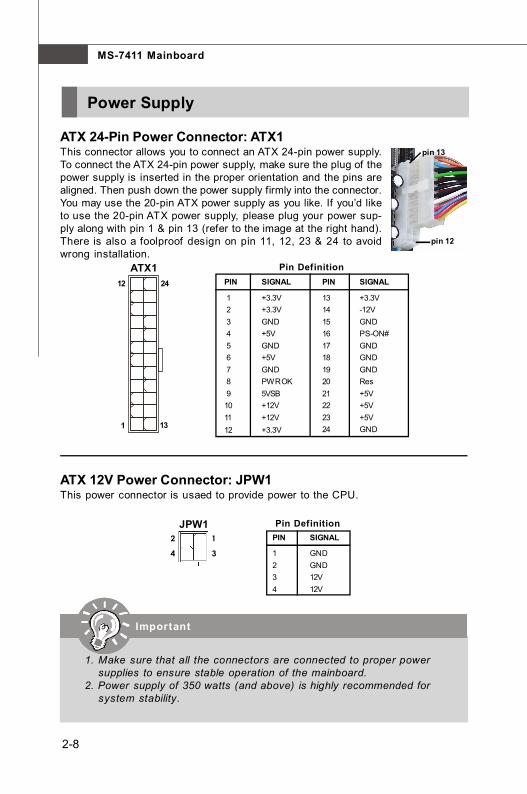
ATX 24-Pin Power Connector: ATX1This connector allows you to connect an ATX 24-pin power supply.To connect the ATX 24-pin power supply, make sure the plug of thepower supply is inserted in the proper orientation and the pins arealigned. Then push down the power supply firmly into the connector.You may use the 20-pin ATX power supply as you like. If you’d liketo use the 20-pin ATX power supply, please plug your power sup-ply along with pin 1 & pin 13 (refer to the image at the right hand).There is also a foolproof design on pin 11, 12, 23 & 24 to avoidwrong installation.
ATX 12V Power Connector: JPW1This power connector is usaed to provide power to the CPU.
1. Make sure that all the connectors are connected to proper powersupplies to ensure stable operation of the mainboard.
2. Power supply of 350 watts (and above) is highly recommended forsystem stability.
pin 12
pin 13
ATX124
131
12 PIN SIGNAL
13 +3.3V14 -12V15 GND16 PS-ON#17 GND18 GND19 GND20 Res21 +5V22 +5V23 +5V24 GND
PIN SIGNAL
1 +3.3V 2 +3.3V 3 GND 4 +5V 5 GND 6 +5V 7 GND 8 PWR OK 9 5VSB10 +12V11 +12V12 +3.3V
Pin Definition
JPW11
34
2 PIN SIGNAL
1 GND2 GND3 12V4 12V
Pin Definition

2-9
Hardware Setup
Back Panel
ComponentVideo-Out (RGB)
Audio RCA-In/ Out
3 RCA jacks.(interlaced or progressive scan)(supports 720p, 1080i HDTV)Red colour: PrGreen colour: YBlue colour: Pb(not all modes support DVD playback dueto content protection )
1. Front channelsRed colour: Line-out (R)White colour: Line-out (L)
2. Subwoofer channelPurple colour: Subwoofer-out
3. Red colour: Line-in (R)White colour: Line-in (L)
VGA-Out 15-pin D-sub
IEEE 1394
Digital Video /Audio-Out
USB 2.0
LAN (RJ45)
HDMI (High Definition Multimedia Interface Support)
(supports 720p, 1080i, 1080p HDTV)
Four 4-pin USB 2.0 ports (High Speed)
Ethernet 10/ 100/ 100/ 1000
6-pin DV input/ output for Digital Videoor other device
Black colour: Coaxial S/PDIF OutputOrange colour: Coaxial S/PDIF Input
Digital Audio-Out
1.
2.
3.

2-10
MS-7411 Mainboard
Important
Connector
IDE Connector: IDE1This connector supports IDE hard disk drives, optical disk drives and other IDE devices.
If you install two IDE devices on the same cable, you must configurethe drives separately to master/ slave mode by setting jumpers.Refer to IDE device’s documentation supplied by the vendors forjumper setting instructions.
IDE1
2-11
Hardware Setup
Important
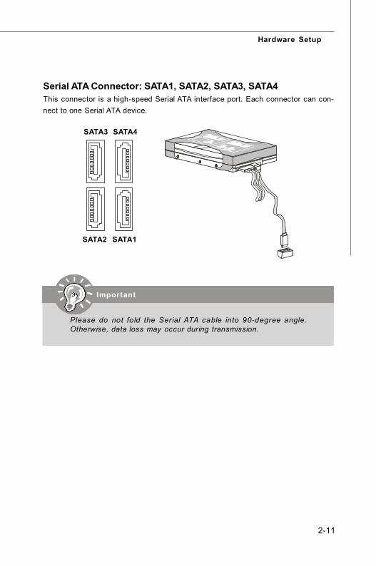
Serial ATA Connector: SATA1, SATA2, SATA3, SATA4This connector is a high-speed Serial ATA interface port. Each connector can con-nect to one Serial ATA device.
Please do not fold the Serial ATA cable into 90-degree angle.Otherwise, data loss may occur during transmission.
SATA2 SATA1
SATA4SATA3

2-12
MS-7411 Mainboard
Serial Port Connector: JCOMThis connector is a 16550A high speed communications port that sends/receives 16bytes FIFOs. You can attach a serial device to it.
PIN SIGNAL1 SOUTA2 GROUND3 Key (no pin)4 GROUND5 SINA6 VCC5
Pin Definition
JCOM
12
56
Fan Power Connector: CPU_FAN1, SYS_FAN1, PWR_FAN1The fan power connectors support system cooling fan with +12V. When connectingthe wire to the connectors, always note that the red wire is the positive and shouldbe connected to the +12V; the black wire is Ground and should be connected to GND.If the mainboard has a System Hardware Monitor chipset onboard, you must use aspecially designed fan with speed sensor to take advantage of the CPU fan control.
SYS_FAN1
SENSOR+12VGND
Control
CPU_FAN1PWR_FAN1
SE
NS
OR
+12VG
ND
CO
NTRO
L
Important
1. Please refer to the recommended CPU fans at processor’s officialwebsite or consult the vendors for proper CPU cooling fan.
2. CPU_FAN1 supports fan control. You can activate the Smart Fanfunction in the BIOS Setup Utility to automatically control the CPUfan speed according to the actual CPU temperature.
3. Fan/ heatsink with 3 or 4 pins are both available for CPU_FAN1.

2-13
Hardware Setup
CD-In Connector: CD_INThis connector is provided for exaternal audio input.
Front Panel Audio Connector: JAUD1This connector allows you to connect the front panel audio and is compliant withIntel® Front Panel I/O Connectivity Design Guide.
CD_IN
GND
RL
PIN SIGNAL DESCRIPTION
1 MIC_L Microphone - Left channel2 GND Ground3 MIC_R Microphone - Right channel4 PRESENCE# Active low signal-signals BIOS that a High Definition Audio dongle
is connected to the analog header. PRESENCE# = 0 when aHigh Definition Audio dongle is connected
5 LINE out_R Analog Port - Right channel6 MIC_JD Jack detection return from front panel microphone JACK17 Front_JD Jack detection sense line from the High Definition Audio CODEC
jack detection resistor network8 NC No control9 LINE out_L Analog Port - Left channel10 LINEout_JD Jack detection return from front panel JACK2
Pin Definition
JAUD112
910

2-14
MS-7411 Mainboard
Important
Front USB Connector: JUSB0, JUSB1, JUSB2, JUSB3This connector, compliant with Intel® I/O Connectivity Design Guide, is ideal for con-necting high-speed USB interface peripherals such as USB HDD, digital cameras,MP3 players, printers, modems and the like.
Note that the pins of VCC and GND must be connected correctly toavoid possible damage.
JUSB0/ 1/ 2/ 312
910
USB 2.0 Bracket(Optional)
PIN SIGNAL PIN SIGNAL1 VCC 2 VCC
3 USB0- 4 USB1-5 USB0+ 6 USB1+
7 GND 8 GND
9 Key (no pin) 10
Pin Definition
CIR Connector: CIR1This connector allows you to connect to consumer infrared devices.
CIR11 5
Pin DefinitionPin Signal
1 CIRTX2 GND3 CIRRX4 NC5 VCC5

2-15
Hardware Setup
Front Panel Connector: JFP1This connector is provided for electrical connection to the front panel switches/LEDsand is compliant with Intel® Front Panel I/O Connectivity Design Guide.
IEEE1394 Connector: J1394_2This connector allows you to connect the IEEE1394 device via an optional IEEE1394bracket.
JFP1 12
910
HDDLED
ResetSwitch
PowerLED
PowerSwitch
+ +
+
- -
-
PIN SIGNAL DESCRIPTION
1 HD_LED + Hard disk LED pull-up2 FP PWR/SLP MSG LED pull-up3 HD_LED - Hard disk active LED4 FP PWR/SLP MSG LED pull-up5 RST_SW - Reset Switch low reference pull-down to GND6 PWR_SW + Power Switch high reference pull-up7 RST_SW + Reset Switch high reference pull-up8 PWR_SW - Power Switch low reference pull-down to GND9 RSVD_DNU Reserved. Do not use.
Pin Definition
Pin DefinitionPIN SIGNAL PIN SIGNAL
1 TPA+ 2 TPA-
3 Ground 4 Ground
5 TPB+ 6 TPB-
7 Cable power 8 Cable power
9 Key (no pin) 10 Ground
J1394_2 1 2
9 10
IEEE1394 Bracket(Optional)

2-16
MS-7411 Mainboard
Jumper
Clear CMOS Jumper: CLR_CMOS2There is a CMOS RAM onboard that has a power supply from an external battery tokeep the dasta of system configuration. With the CMOS RAM, the system can auto-matically boot OS every time it is turned on. If you want to clear the system configuration,set the jumper to clear data.
Keep Data
1 3
Clear Data
1 3
CLR_CMOS21
Important
You can clear CMOS by shorting 2-3 pin while the system is off.Then return to 1-2 pin position. Avoid clearing the CMOS while thesystem is on; it will damage the mainboard.
2-17
Hardware Setup
Slot
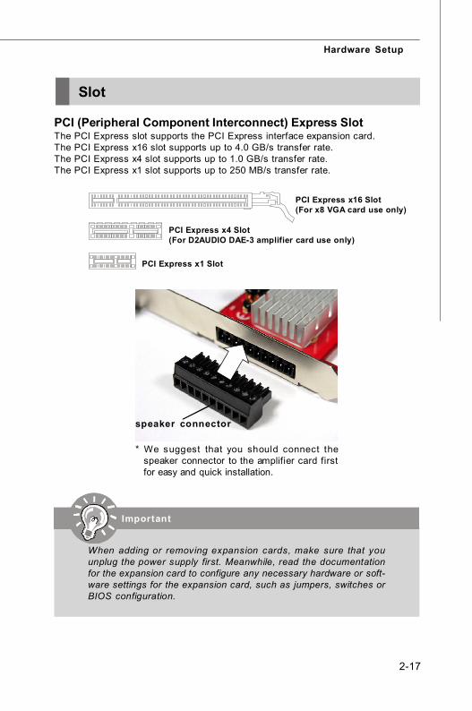
PCI (Peripheral Component Interconnect) Express SlotThe PCI Express slot supports the PCI Express interface expansion card.The PCI Express x16 slot supports up to 4.0 GB/s transfer rate.The PCI Express x4 slot supports up to 1.0 GB/s transfer rate.The PCI Express x1 slot supports up to 250 MB/s transfer rate.
PCI Express x16 Slot(For x8 VGA card use only)
PCI Express x4 Slot(For D2AUDIO DAE-3 amplifier card use only)
PCI Express x1 Slot
* We suggest that you should connect thespeaker connector to the amplifier card firstfor easy and quick installation.
speaker connector
When adding or removing expansion cards, make sure that youunplug the power supply first. Meanwhile, read the documentationfor the expansion card to configure any necessary hardware or soft-ware settings for the expansion card, such as jumpers, switches orBIOS configuration.
Important


3-1
BIOS Setup
Chapter 3
BIOS Setup
This chapter provides you with the information aboutthe BIOS setup program and allows you to configurethe system for optimum use. You may need to run thesetup program when:
An error message appears on the screen during thesystem booting up and requests you to run SETUP.
You want to change the default settings for custom-ized features.

3-2
MS-7411 Mainboard
Entering Setup
Power on the computer and the system will start POST (Power On Self Test) process.When the message below appears on the screen, press <DEL> key to enter Setup.
Press DEL to enter SETUP
If the message disappears before you respond and you still wish to enter Setup,restart the system by turning it OFF and On or pressing the RESET button. You mayalso restart the system by simultaneously pressing <Ctrl>, <Alt> and <Delete> keys.
1. The items under each BIOS category described in this chapter areunder continuous update for better system performance. Therefore,the description may be slightly different from the latest BIOS andshould be held for reference only.
2. Upon boot-up, the 1st line appearing after the memory count is theBIOS version. It is usually in the format:
A7411AMS V1.0 071508 where:
1st digit refers to BIOS maker as A = AMI, W = AWARD and P =PHOENIX.2nd - 5th digit refers to the model number.6th digit refers to the chipset as I = INTEL, A = AMD, N = NVIDIA and V= VIA.7th - 8th digit refers to the customer as MS = all standard customers.V1.0 refers to the BIOS version.071508 refers to the date this BIOS was released.
Important

3-3
BIOS Setup
Control Keys<↑> Move to the previous item
<↓> Move to the next item
<←> Move to the item in the left hand
<→> Move to the item in the right hand
<Enter> Select the item
<Esc> Jumps to the exit menu or returns to the main menu from a submenu
<+/PU> Increase the numeric value or make changes
<-/PD> Decrease the numeric value or make changes
<F1> General help
<F10> Save all the CMOS changes and exit
Getting HelpAfter entering the Setup menu, the first menu you will see is the Main Menu.
Main MenuThe main menu lists the setup functions you can make changes to. You can use thearrow keys (↑↓) to select the item. The on-line description of the highlighted setupfunction is displayed at the bottom of the screen.
Sub-MenuIf you find a right pointer symbol (as shown inthe right view) appears to the left of certainfields that means a sub-menu can be launchedfrom this field. A sub-menu contains additionaloptions for a field parameter. You can use arrow keys (↑↓) to highlight the field andpress <Enter> to call up the sub-menu. Then you can use the control keys to entervalues and move from field to field within a sub-menu. If you want to return to themain menu, just press the <Esc>.
General Help <F1>The BIOS setup program provides a General Help screen. You can call up this screenfrom any menu by simply pressing <F1>. The Help screen lists the appropriate keysto use and the possible selections for the highlighted item. Press <Esc> to exit theHelp screen.
3-4
MS-7411 Mainboard
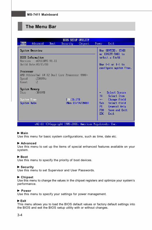
MainUse this menu for basic system configurations, such as time, date etc.
AdvancedUse this menu to set up the items of special enhanced features available on yoursystem.
BootUse this menu to specify the priority of boot devices.
SecurityUse this menu to set Supervisor and User Passwords.
ChipsetUse this menu to change the values in the chipset registers and optimize your system’sperformance.
PowerUse this menu to specify your settings for power management.
ExitThis menu allows you to load the BIOS default values or factory default settings intothe BIOS and exit the BIOS setup utility with or without changes.
The Menu Bar

3-5
BIOS Setup
Main
BIOS InformationThis item shows the information of AMI® BIOS. (Read-only)
ProcessorThis item shows the information of Processor. (Read-only)
System MemoryThis item shows the information of System Memory. (Read-only)
System TimeThis allows you to set the system time that you want (usually the current time). Thetime format is <hour> <minute> <second>.
System DateThis allows you to set the system date that you want (usually the current date). Thedate format is <day> <month> <date> <year>.
[Day] Day of the week, from Sun to Sat, determined by BIOS.[Month] The month from Jan. through Dec.[Date] The date from 1 to 31 can be keyed by numeric function keys.[Year] The year can be adjusted by users.

3-6
MS-7411 Mainboard
Advanced
WARNING: Setting wrong values in below sections may cause system tomalfunction.
CPU ConfigurationPress <Enter> and the following sub-menu appears:

3-7
BIOS Setup
Module VersionThis item shows the version of the current USB module. (Read-only)
AGESA VersionThis item shows the version of the AMD® Generic Encapsulated SoftwareArchitecture. (Read-only)
Physical/ Logical CountThese items show the detail CPU information. (Read-only)
AMD AthlonTM 64 X2 Dual Core Processor 4400+
RevisionThis item shows the current status of the processor. (Read-only)
Cache L1/ 2/ 3Cache memory is additional memory that is much faster than conventionalDRAM (system memory). When the CPU requests data, the system transfersthe requested data from the main DRAM into cache memory, for even fasteraccess by the CPU. This item shows the internal cache (also known as L1 orlevel 1 cache) and external cache (also known as L2 or level 2 cache).
SpeedThis item shows the current CPU Front Side Bus (FSB) clock speed. (Read-only)

3-8
MS-7411 Mainboard
NB ClkThis item allows you to select the NB clock.
Current/ Maximum FSB MultiplierThese items show the current/ maximum FSB Multiplier. (Read-only)
GART Error ReportingThe GART is a device that translates a range of physical address space,called the GART aperture, to a logical address based on page tables in systemmemory. This item is used to Enable or Disable GART Error Reporting.
Microcode UpdateThis item is used to Enable or Disable Update CPU Microcode.
Secure Virtual Machine ModeThis item is used to enable or disable the SVM (Secure Virtual Machine) mode.
PowerNowThis item allows you to enable or disable AMD® PowerNow technology. Whenset to Enabled, the system always operates in a conserve power mode. If youwant optimize the processor, set this item to Disabled, so that the processor’sspeed will vary depending on the use of your operating system and applications.Default setting is set to Enabled.

3-9
BIOS Setup
IDE ConfigurationPress <Enter> and the following sub-menu appears:
OnBoard PCI IDE ControllerThe integrated peripheral controller contains a PCI IDE interface with supportfor two IDE channels. Select [Disabled] to disable the integrated IDE controller,[Primary] to enable only the primary IDE controller, [Secondary] to enable onlythe secondary IDE controller, or [Both] to enable both IDE controllers.
Primary/ Secondary/ Third/ Fourth IDE Master/ SlavePress <Enter> and the following sub-menu appears:
TypePress PgUp/ <+> or PgDn/ <-> to select [Manual], [None] or [Auto] type.Note that the specif ications of your drive must match with the drivetable. The hard disk will not work properly if you enter improper infor-mation for this category. If your hard disk drive type is not matched orlisted, you can use [Manual] to define your own drive type manually.

3-10
MS-7411 Mainboard
LBA/ Large ModeThis item allows you to enable or disable the LBA (Logical Block Address,the logical block size in hard disk) mode.
Block (Multi-Sector Transfer)When the setting is Auto, it will read or write more sector at every circleto enhance the hard disk performance. Setting options: [Auto], [Disabled].
PIO ModeThe PIO (Programmed Input/ Output) Mode let you set a PIO mode (0-4)for the IDE devices that the onboard IDE interface supports. Modes 0through 4 provide successively increased performance. In Auto mode,the system automatically determines the best mode for each device.The settings are: [Auto], [Mode 0], [Mode 1], [Mode 2], [Mode 3], [Mode4].
DMA ModeThis item allows you to enable or disable the DMA (Direct MemoryAccess) mode.
S.M.A.R.TThis allows you to activate the S.M.A.R.T. (Self-Monitoring Analysis &Reporting Technology) capability for the hard disks. S.M.A.R.T is autility that monitors your disk status to predict hard disk failure. Thisgives you an opportunity to move data from a hard disk that is going tofail to a safe place before the hard disk becomes off line.
32Bit Data TransferThe IDE interface in the integrated peripherals controller supports 32-bit data transfers. Select [Enabled] only if your IDE hard drives can alsosupport 32-bit transfer mode.

3-11
BIOS Setup
SuperIO ConfigurationPress <Enter> and the following sub-menu appears:
Serial Port1 AddressThis item specifies the base I/O port address of the onboard Serial Port 1 (COMA). Select [Auto] allows AMI® BIOS to automatically determine the correct baseI/O port address. Setting options: [3F8/ IRQ4], [2F8/ IRQ3], [3E8/ IRQ4], [2E8/IRQ3] and [Disabled].
Serial Port1 ModeThis item allows you to specify the operation mode for serial port1. Settingoptions: [Normal], [IrDA], [ASKIR].
[Normal] RS-232C Serial Port[IrDA] IrDA-compliant Serial Infrared Port[ASKIR] Amplitude Shift Keyed Infrared Port
OnBoard CIR PortThis item is used to Enable or Disable OnBoard Consumer Remote Control (TVremote IR).
Chassis IntrusionThe field enables or disables the feature of recording the chassis intrusionstatus and issuing a warning message if the chassis is once opened. To clearthe warning message, set the f ield to [Reset]. The setting of the f ield willautomatically return to [Enabled] later.

3-12
MS-7411 Mainboard
Hardware Health ConfigurationPress <Enter> and the following sub-menu appears:
H/W Health FunctionThis setting enables Hardware Health Monitoring Device.
CPU/ System/ Power FAN Mode SettingThis item allows you to specify the operation mode for CPU/ System/ PowerFAN. Setting options: [Full On mode], [Automatic mode], [PWM Manually mode].
[Full On mode] Fan work on full speed.[Automatic mode] The PWM value is subject to the temperature
inputs linear changs.[PWM Manually mode] The PWM value is subject to the value set by
user.
CPU Temperature, System Temperature1/ 2, CPU/ System/ Power FanSpeedThese items display the current status of all of the monitored hardware devicesand components such as CPU temperature and system fan speed.
+3.30V, +5.00V, VCC, +12.0V, CPU CoreThese items display the current status of all of the monitored hardware devicesand components such as CPU voltages.
3-13
BIOS Setup
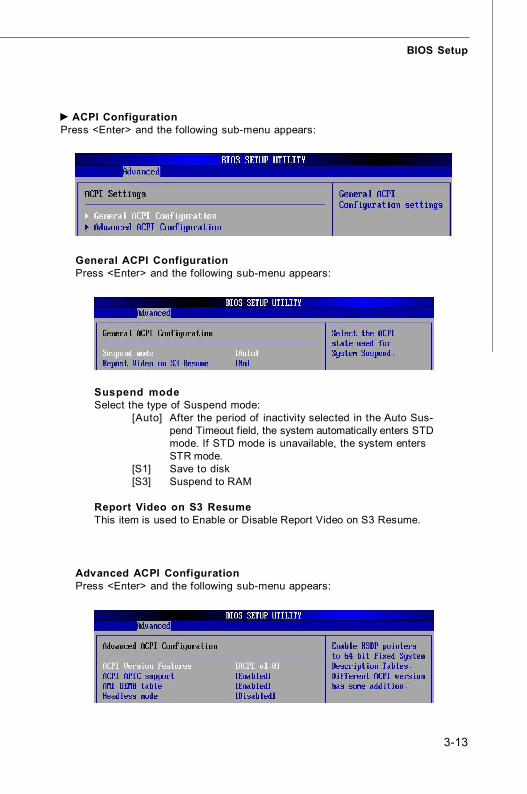
ACPI ConfigurationPress <Enter> and the following sub-menu appears:
Suspend modeSelect the type of Suspend mode:
[Auto] After the period of inactivity selected in the Auto Sus-pend Timeout field, the system automatically enters STDmode. If STD mode is unavailable, the system entersSTR mode.
[S1] Save to disk[S3] Suspend to RAM
Report Video on S3 ResumeThis item is used to Enable or Disable Report Video on S3 Resume.
General ACPI ConfigurationPress <Enter> and the following sub-menu appears:
Advanced ACPI ConfigurationPress <Enter> and the following sub-menu appears:

3-14
MS-7411 Mainboard
ACPI Version FeaturesThis item is used to select the ACPI Features.
ACPI APIC supportThis item is used to Enable or Disable support ACPI APIC.
AMI OEMB tableThis item is used to Enable or Disable AMI® OEM ACPI table.
Headless modeThis feature allows operating without a keyboard, monitor or mouse.To run in headless mode, both BIOS and operating system must supportheadless operation. When enabled, the BIOS will update the FACP toindicate support for headless operation. Operating systems that sup-port headless operation can proceed to boot in headless mode.

3-15
BIOS Setup
Event Log ConfigurationPress <Enter> and the following sub-menu appears:
View Event LogThis item is used to view the Event Log which occurred during post or runtime.
Mark all events as readThis item is used to mark all events as read and they do not display at next time.
Clear Event LogThis item is used to clear all events in nvram and they do not display at nexttime.

3-16
MS-7411 Mainboard
USB ConfigurationPress <Enter> and the following sub-menu appears:
Module Version - 2.24.3-13.4
USB Devices Enabled: 1 Keyboard, 1 Drive
Legacy USB SupportSet to [Enabled] if your need to use any USB 1.1/ 2.0 device in the operatingsystem that does not support or have any USB 1.1/ 2.0 driver installed, suchas DOS and SCO Unix. Set to [Disabled] only if you want to use any USB deviceother than the USB mouse.
USB 2.0 Controller ModeSet to [Enabled] if you need to use any USB 2.0 device in the operating systemthat does not support or have any USB 2.0 driver installed, such as DOS andSCO Unix.
BIOS EHCI Hand-OffThis is a workaround for OSes without EHCI hand-off support. The EHCIownership change should claim by EHCI driver.
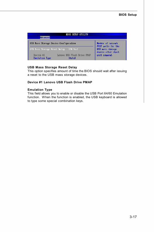
USB Mass Storage Device ConfigurationPress <Enter> and the following sub-menu appears:
3-17
BIOS Setup
USB Mass Storage Reset DelayThis option specifies amount of time the BIOS should wait after issuinga reset to the USB mass storage devices.
Device #1 Lenovo USB Flash Drive PMAP
Emulation TypeThis field allows you to enable or disable the USB Port 64/60 Emulationfunction. When the function is enabled, the USB keyboard is allowedto type some special combination keys.

3-18
MS-7411 Mainboard
Boot
Quick BootSetting the item to [Enabled] allows the system to boot within 5 seconds sinceit will skip some check items.
Quiet BootIf set to [enabled] the OS boots straight to the GUI without showing the POSTscreen, if set to [disabled] it boots to the POST first.
Boot Settings ConfigurationPress <Enter> and the following sub-menu appears:
3-19
BIOS Setup
Bootup Num-LockThis setting is to set the Num Lock status when the system is powered on.Setting to [On] will turn on the Num Lock key when the system is powered on.Setting to [Off] will allow users to use the arrow keys on the numeric keypad.
Wait For ‘F1’ If ErrorThis BIOS feature controls the system's response when an error is detectedduring the boot sequence. When enabled, the BIOS will halt the boot sequencewhen an error is detected. You will need to press the F1 button at this point. Itbrings you to the BIOS setup menu where you can adjust the settings to fix theproblem. When disabled, the BIOS will not halt the boot sequence, even whenan error is detected. The system will continue to boot into the operating system.
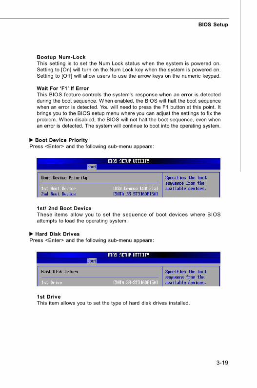
1st/ 2nd Boot DeviceThese items allow you to set the sequence of boot devices where BIOSattempts to load the operating system.
Boot Device PriorityPress <Enter> and the following sub-menu appears:
Hard Disk DrivesPress <Enter> and the following sub-menu appears:
1st DriveThis item allows you to set the type of hard disk drives installed.

3-20
MS-7411 Mainboard
1st DriveThis item allows you to set the type of removable drives installed.
Removable DrivesPress <Enter> and the following sub-menu appears:
3-21
BIOS Setup
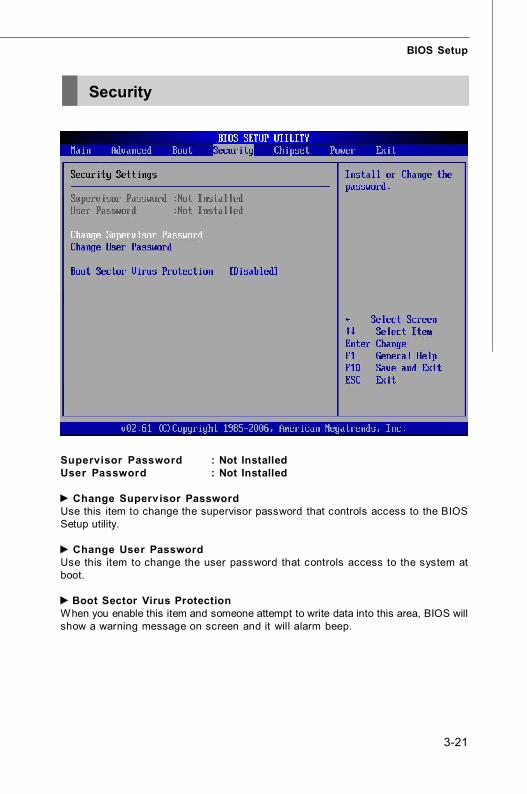
Security
Supervisor Password : Not InstalledUser Password : Not Installed
Change Supervisor PasswordUse this item to change the supervisor password that controls access to the BIOSSetup utility.
Change User PasswordUse this item to change the user password that controls access to the system atboot.
Boot Sector Virus ProtectionWhen you enable this item and someone attempt to write data into this area, BIOS willshow a warning message on screen and it will alarm beep.
3-22
MS-7411 Mainboard
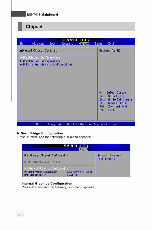
Chipset
NorthBridge ConfigurationPress <Enter> and the following sub-menu appears:
Internal Graphics ConfigurationPress <Enter> and the following sub-menu appears:

3-23
BIOS Setup
Primary Video ControllerThis item used to select the Primary Video Controller interface.
AMD 780 HD AudioThis item used to Enable or Disable the AMD® 780M(NB) HD Audio.
Internal Graphics ModeThe field allows you to select whether the UMA (Unif ied MemoryArchitecture) or Sideport (Local Frame Buffer) memory allocated forvideo memory.
UMA Frame Buffer SizeFrame Buffer is the video memory that stores data for video display(frame). This field is used to determine the memory size for FrameBuffer. Larger frame buffer size increases video performance.
SIDEPORT Clock SpeedThis item is used to adjust the Side Port Memory Clock.
GFX Engine Clock OverrideThis item is used to adjust the GFX Engine Clock Clock.

3-24
MS-7411 Mainboard
HD Audio Azalia DeviceThis item is used to Enable or Disable the AMD SB700(SB) HD Audio.
OnChip SATA Channel/ TypeThis setting is used to specify the SATA controller. The settings are:
[Disabled] Disable the SATA controller.[Auto] PATA and SATA will be arranged by BIOS, and you
will be able to see the IDE Device status listed in StandardCOMS Features.
[Legacy Mode] PATA and SATA will be combined. Max. of 2 IDE drivesin each channel are available.
[Native IDE] PATA and SATA will both be enabled. Max. of 6 IDEdrives are supported.
SATA IDE Combined ModeThis item is used to Enable or Disable the SATA IDE Combined Mode.
PATA Channel ConfigThis item is used to select the PATA Channel.
SouthBridge ConfigurationPress <Enter> and the following sub-menu appears:

3-25
BIOS Setup
OnBoard Peripherals ConfigurationPress <Enter> and the following sub-menu appears:
Realtek 8111C PCIE NICThis item is used to Enable or Disable OnBoard LAN (Realtek® 8111C) Device.
Realtek 8111C Option ROMThis item is used to Enable or Disable OnBoard LAN (Realtek® 8111C) OptionROM.
Onboard 1394 ControllerThis setting is used to Enable or Disable the onboard IEEE 1394 controller.

3-26
MS-7411 Mainboard
Power
Power Management/ APMSetting to [Enabled] will activate an Advanced Power Management (APM) device toenhance Max Saving mode and stop CPU internal clock.
Power Button ModeThis feature allows users to configure the Power Button function. Settings are:
[Off] The power button functions as a normal power-on/-off button.[Suspend] When you press the power button, the computer enters the
suspend/ sleep mode, but if the button is pressed for morethan four seconds, the computer is turned off.
Resume on PMEWhen setting to [Enabled], this setting allows your system to be awakened from thepower saving modes through any event on PME (Power Management Event).
RTC ResumeWhen [Enabled], your can set the date and time at which the RTC (real-time clock)alarm awakens the system from Suspend mode.

3-27
BIOS Setup
Restore on AC Power LossThis setting specif ies whether your system will reboot after a power failure orinterrupt occurs. Available settings are:
[Off] Leaves the computer in the power off state.[On] Leaves the computer in the power on state.[Last State] Restores the system to the previous status before power
failure or interrupt occurred.

3-28
MS-7411 Mainboard
Exit
Save Changes and ExitSave changes to CMOS and exit setup.
Discard Changes and ExitAbandon all changes and exit setup.
Discard ChangesAbandon all changes.
Load Optimal DefaultsUse this menu to load the default values set by the mainboard manufacturer specifi-cally for optimal performance of the mainboard.
Load Failsafe DefaultsUse this menu to load the default values set by the BIOS vendor for stablesystemperformance.

Realtek ALC888 AudioAppendix A
The Realtek ALC888 provides 10-channel DAC that si-multaneously supports 7.1 sound playback and 2 chan-nels of independent s tereo sound output (multiplestreaming) through the Front-Out-Left and Front-Out-Right channels.

MS-7411 Mainboard
A-2
You need to install the driver for Realtek ALC888 codec to function properly beforeyou can get access to 2-, 4-, 6-, 8- channel or 7.1+2 channel audio operations.Follow the procedures described below to install the drivers for different operatingsystems.
Installation for Windows 2000/ XP/ VistaFor Windows® 2000, you must install Windows® 2000 Service Pack4 or later beforeinstalling the driver. For Windows® XP, you must install Windows® XP Service Pack1or later before installing the driver.The following illustrations are based on Windows® XP environment and could lookslightly different if you install the drivers in different operating systems.
1. Insert the application CD into the CD-ROM drive. The setup screen will auto-matically appear.
2. Click Realtek HD Audio Driver.
Installing the Realtek HD Audio Driver
Important
The HD Audio Configuration software utility is under continuous updateto enhance audio applications. Hence, the program screens shown here inthis section may be slightly different from the latest software utility and shallbe held for reference only.
Click here

A-3
Realtek ALC888 Audio
3. Click Next to install the Realtek High Definition Audio Driver.
Click here
Select thisoption
4. Click Finish to restart the system.
Click here
MS-7411 Mainboard
A-4
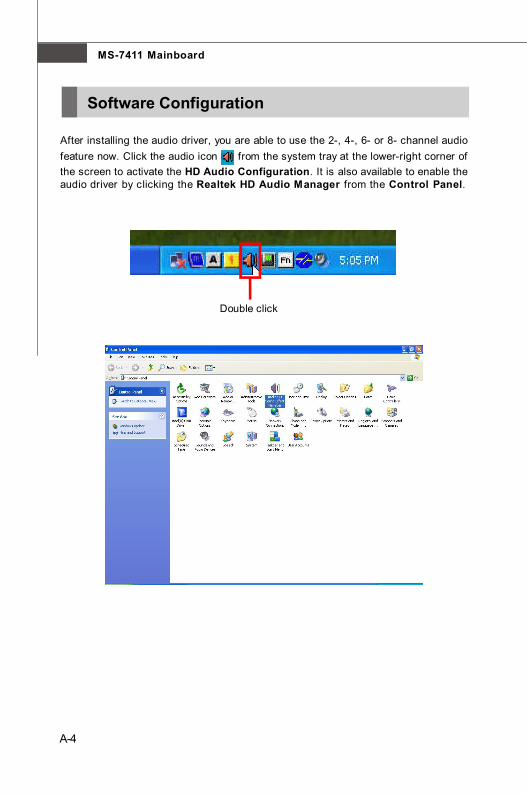
After installing the audio driver, you are able to use the 2-, 4-, 6- or 8- channel audiofeature now. Click the audio icon from the system tray at the lower-right corner ofthe screen to activate the HD Audio Configuration. It is also available to enable theaudio driver by clicking the Realtek HD Audio Manager from the Control Panel.
Double click
Software Configuration

A-5
Realtek ALC888 Audio
Sound Effect
Environment SimulationYou will be able to enjoy different sound experience by pulling down the arrow,totally 23 kinds of sound effect will be shown for selection. Realtek HD Audio SoundManager also provides five popular settings “Stone Corridor”, “Bathroom”, “Sewerpipe”, “Arena” and “Audio Corridor” for quick enjoyment.
You may choose the provided sound effects, and the equalizer will adjust automatically.If you like, you may also load an equalizer setting or make an new equalizer setting tosave as an new one by using the “Load EQ Setting” and “Save Preset” button,click “Reset EQ Setting” button to use the default value, or click “Delete EQ Set-ting” button to remove a preset EQ setting.
There are also other pre-set equalizer models for you to choose by clicking “Others”under the Equalizer part.
Here you can select a sound effect you like from the Environment list.

MS-7411 Mainboard
A-6
SaveThe settings are savedpermanently for futureuse
Reset10 bands of equalizerwould go back to the de-fault setting
Enable / DisableTo disable, you can tem-porarily s top the soundeffect without losing thesettings
LoadWhenever you would like touse preload settings, simplyclick this, the whole list willbe shown for your selection.
DeleteTo delete the pre-saved settings which are created from previous steps.
Equalizer SelectionEqualizer frees users from default settings; users may create their owned preferredsettings by utilizing this tool.
10 bands of equalizer, ranging from 100Hz to 16KHz.

A-7
Realtek ALC888 Audio
Raise the key
Lower the key
Remove thehuman voice
Frequently Used Equalizer SettingRealtek recognizes the needs that you might have. By leveraging our long experienceat audio field, Realtek HD Audio Sound Manager provides you certain optimized equal-izer settings that are frequently used for your quick enjoyment.
[How to Use It]Other than the buttons “Pop” “Live” “Club” & “Rock” shown on the page, to pull downthe arrow in “Others”, you will find more optimized settings available to you.
Karaoke ModeKaraoke mode brings Karaoke fun back home. Simply using the music you usuallyplay, Karaoke mode can help you eliminate the vocal of the song or adjust the key toaccommodate your range.1.Vocal Cancellation: Single click on “Voice Cancellation”, the vocal of the song would be eliminated, while the background music is still in place, and you can be that singer!2.Key Adjustment: Using “Up / Down Arrow” to find a key which better fits your vocal range.
MS-7411 Mainboard
A-8
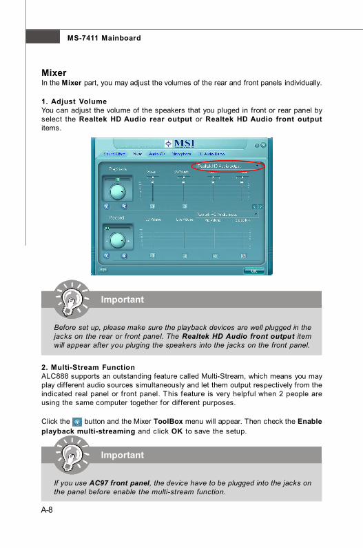
MixerIn the Mixer part, you may adjust the volumes of the rear and front panels individually.
1. Adjust VolumeYou can adjust the volume of the speakers that you pluged in front or rear panel byselect the Realtek HD Audio rear output or Realtek HD Audio front outputitems.
2. Multi-Stream FunctionALC888 supports an outstanding feature called Multi-Stream, which means you mayplay different audio sources simultaneously and let them output respectively from theindicated real panel or front panel. This feature is very helpful when 2 people areusing the same computer together for different purposes.
Click the button and the Mixer ToolBox menu will appear. Then check the Enableplayback multi-streaming and click OK to save the setup.
Important
Before set up, please make sure the playback devices are well plugged in thejacks on the rear or front panel. The Realtek HD Audio front output itemwill appear after you pluging the speakers into the jacks on the front panel.
Important
If you use AC97 front panel, the device have to be plugged into the jacks onthe panel before enable the multi-stream function.

A-9
Realtek ALC888 Audio
W hen you are playing the f irst audio source (for example: use W indows MediaPlayer to play DVD/VCD), the output will be played from the rear panel, which is thedefault setting.
Then you must to select the Realtek HD Audio front output from the scroll listfirst, and use a different program to play the second audio source (for example: useWinamp to play MP3 files). You will find that the second audio source (MP3 music) willcome out from the Line-Out audio jack of Front Panel.
MS-7411 Mainboard
A-10
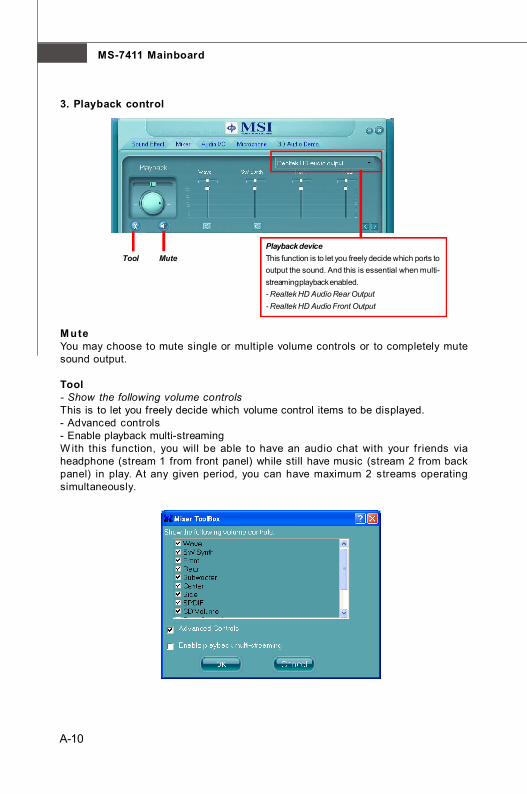
3. Playback control
Playback deviceThis function is to let you freely decide which ports tooutput the sound. And this is essential when multi-streaming playback enabled.- Realtek HD Audio Rear Output- Realtek HD Audio Front Output
Tool Mute
MuteYou may choose to mute single or multiple volume controls or to completely mutesound output.
Tool- Show the following volume controlsThis is to let you freely decide which volume control items to be displayed.- Advanced controls- Enable playback multi-streamingW ith this function, you will be able to have an audio chat with your friends viaheadphone (stream 1 from front panel) while still have music (stream 2 from backpanel) in play. At any given period, you can have maximum 2 streams operatingsimultaneously.

A-11
Realtek ALC888 Audio
4. Recording control
Recording device-Back Line in/Mic, Front Lin in-Realtek HD Audio Input
MuteYou may choose to mute single or multiple volume controls or to completely mutesound input.Tool- Show the following volume controlsThis is to let you freely decide which volume control items to be displayed.- Enable recording multi-streaming
Tool Mute
Important
ALC888 allows you to record the CD, Line, Mic and Stereo Mix channelssimultaneously, frees you from mixing efforts. At any given period, you maychoose 1 of the following 4 channels to record.
MS-7411 Mainboard
A-12
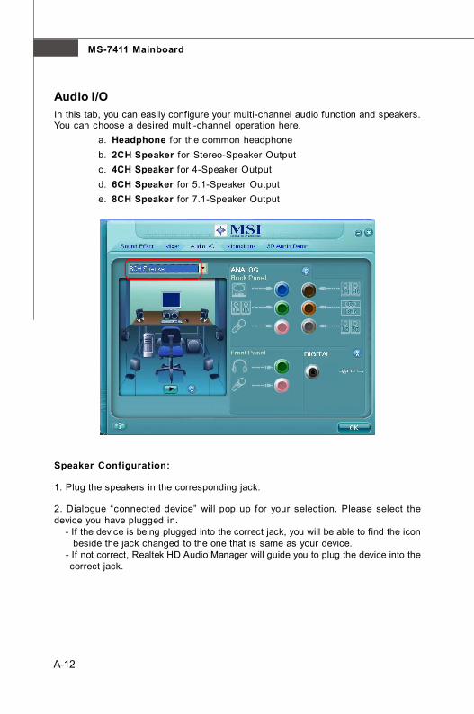
Audio I/OIn this tab, you can easily configure your multi-channel audio function and speakers.You can choose a desired multi-channel operation here.
a. Headphone for the common headphoneb. 2CH Speaker for Stereo-Speaker Outputc. 4CH Speaker for 4-Speaker Outputd. 6CH Speaker for 5.1-Speaker Outpute. 8CH Speaker for 7.1-Speaker Output
Speaker Configuration:
1. Plug the speakers in the corresponding jack.
2. Dialogue “connected device” will pop up for your selection. Please select thedevice you have plugged in. - If the device is being plugged into the correct jack, you will be able to find the icon beside the jack changed to the one that is same as your device. - If not correct, Realtek HD Audio Manager will guide you to plug the device into the correct jack.

A-13
Realtek ALC888 Audio
Connector Settings
Click to access connector settings.
Disable front panel jack detection (option)Find no function on front panel jacks? Please check if front jacks on your system areso-called AC’97 jacks. If so, please check this item to disable front panel jack detection.
Mute rear panel output when front headphone plugged in.
Enable auto popup dialogue, when device has been plugged inOnce this item checked, the dialog “Connected device” would automatically pop upwhen device plugged in.

MS-7411 Mainboard
A-14
S/PDIFShort for Sony/Philips Digital Interface, a standard audio file transfer format. S/PDIFallows the transfer of digital audio signals from one device to another without havingto be converted first to an analog format. Maintaining the viability of a digital signalprevents the quality of the signal from degrading when it is converted to analog.
Output Sampling Rate 44.1KHz: This is recommend while playing CD. 48KHz: This is recommended while playing DVD or Dolby. 96KHz: This is recommended while playing DVD-Audio. 192KHz: This is recommended while playing High quality Audio.
Output Source Output digital audio source: The digital audio format (such as .wav, .mp3,.midi etc) will come out through S/PDIF-Out.

A-15
Realtek ALC888 Audio
Test SpeakersYou can select the speaker by clicking it to test its functionality. The one you selectwill light up and make testing sound. If any speaker fails to make sound, then checkwhether the cable is inserted f irmly to the connector or replace the bad speakerswith good ones. Or you may click the auto test button to test the sounds ofeach speaker automatically.
Subwoofer
Front Right
Rear Right
Center
Front Left
Rear Left
Side Left
Side Right

MS-7411 Mainboard
A-16
MicrophoneIn this tab you may set the function of the microphone. Select the Noise Suppres-sion to remove the possible noise during recording, or select Acoustic EchoCancelltion to cancel the acoustic echo druing recording.
Acoustic Echo Cancelltion prevents playback sound from being recorded by mi-crophone together with your sound. For example, you might have chance to useVOIP function through Internet with your friends. The voice of your friend will comeout from speakers (playback). However, the voice of your friend might also berecorded into your microphone then go back to your friend through Internet. In thatcase, your friend will hear his /her own voice again. W ith AEC(Acoustic EchoCancellation) enabled at your side, your friend can enjoy the benefit with less echo.

A-17
Realtek ALC888 Audio
3D Audio DemoIn this tab you may adjust your 3D positional audio before playing 3D audio applica-tions like gaming. You may also select different environment to choose the mostsuitable environment you like.

MS-7411 Mainboard
A-18
InformationIn this tab it provides some information about this HD Audio Configuration utility,including Audio Driver Version, DirectX Version, Audio Controller & Audio Codec. Youmay also select the language of this utility by choosing from the Language list.
Also there is a selection Show icon in system tray. Switch it on and an icon
will show in the system tray. Right-click on the icon and the Audio Accessoriesdialogue box will appear which provides several multimedia features for you to takeadvantage of.

B-1
SATA RAID
SATA RAIDAppendix B
The Southbridge integrates SATA host controller thatsupports four SATA ports and RAID function for per-formance and reliability.SATA RAID provides support for RAID 0 (Striping), RAID1 (Mirroring), RAID 0+1 (Striping & Mirroring). RAID 0greatly improves hard d isk I/O performance byconcurrently striping data across multiple drives. RAID1 makes sure data is not lost if a drive fails as data issimultaneously written to two drives. Drives configuredfor RAID Striping are said to form a RAID 0 set, whiledrives configured for RAID Mirroring are said to form aRAID 1 set. RAID 0+1 is implemented as a mirroredarray whose segments are RAID 0 arrays. RAID hassame fault tolerance as mirroring and reduces overheadby striping. It needs at least four drives to form a RAID.

MS-7411 Mainboard
B-2
RAID Configuration
Creating and deleting RAID set and performing other RAID setting up operations aredone in the RAID BIOS. During bootup, a screen similar to the one below will appearfor about few seconds. Press <Ctrl-F> to enter the FastBuild utility.
The Fast Build Utility menu screen will appear. The Main Menu is used to choose theoperation to be performed.
Important
Be sure to set the SATA Mode to “RAID” in BIOS (the path is : IntergratedPeripherals => On-Chip ATA Devices => OnChip SATA Controller) be-fore configuting the RAID BIOS.

B-3
SATA RAID
View Drives Assignments
This window displays the model number, capacities and assignment of the drivesphysically attached to the SATA host adapter.

MS-7411 Mainboard
B-4
Define LD (Creating RAID)
The selection of the RAID configuration should be based upon factors includingperformance, data security, and the number of drives available. It is best to carefullyconsider the long-term role of the system and plan the data storage strategy. RAIDsets can be created either automatically, or to allow the greatest flexibility, manually.
1. Press 2 on the Main Menu screen to enter the Define LD Menu.2. Press the arrow keys to highlight an logical drive number you want to define
and press Enter to select it.
and press Enter to select it.
3. On the next screen, use the space key to choose a RAID mode (RAID 0/ 1/0+1) and use the arrow key to move to the Drives Assignments window.• Initialize logical drive, zero the disk drives. RAID 1 or 10 only.

B-5
SATA RAID
• Stripe Block Size, the default 64KB is best for most applications. RAID 0 or 10 only.• Gigabyte Boundary, allows use of slightly smaller replacement drives.• Cache Mode, WriteThru or WriteBack.
4. On the Drives Assignments window, use the arrow key to choose the harddrives which you want to make part of the LD, use the space key to changethe assignment to “Y”. Then press [Ctrl+Y] to save the configuration.
5. A message will show up on the bottom, press any key to save the configura-tion or press [Ctrl-Y] to allocate the RAID capacity manually.
Important
1. The default capacity is the full capacity of the selected hard drives.2. If you allocate the first LD capacity manually, you can create second LD with remaining capacity of the selected hard drives.
MS-7411 Mainboard
B-6
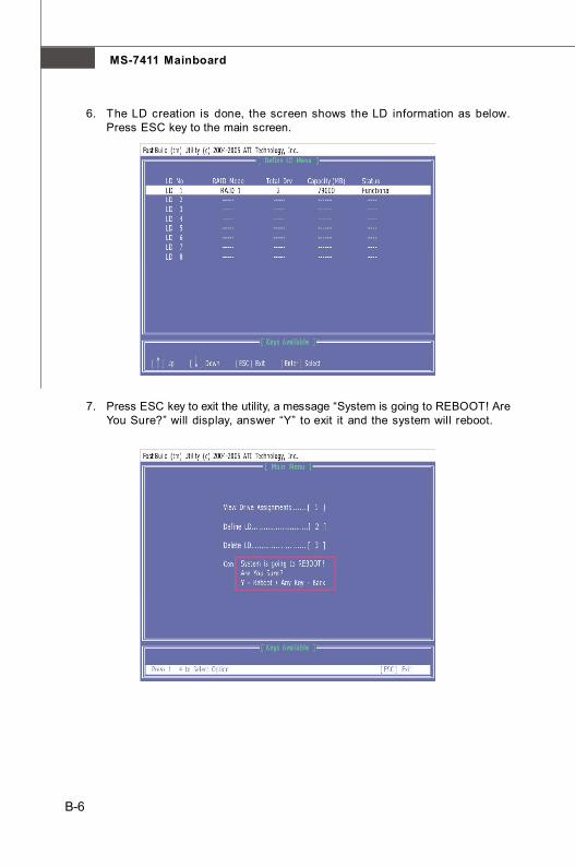
6. The LD creation is done, the screen shows the LD information as below.Press ESC key to the main screen.
7. Press ESC key to exit the utility, a message “System is going to REBOOT! AreYou Sure?” will display, answer “Y” to exit it and the system will reboot.

B-7
SATA RAID
Delete LD (Deleting RAID)
1. Select “Delete LD” on the main screen.2. Choose a LD No you want to delete and press “Del” or “Alt+D” delete the RAID
set.
3. On the next screen, a message will display to inform you, press “Ctrl+Y” todelete the RAID set or other key to abort it. Press “Ctrl+Y” to complete thedeletion.

MS-7411 Mainboard
B-8
Installing the RAID Driver (for bootable RAID Array)1. After you complete the RAID BIOS setup, boot from the Windows CD, and the
Windows XP Setup program starts.2. Press F6 and wait for the W indows Setup screen to appear.
3. Insert the floppy that contains the RAID driver,Press the “S” key to select “SpecifyAdditional Device”.
4. For Windows Vista:During the Operating system installation, after selecting the location to installVista click on “Load Driver” button to install a third party SCSI or RAID driver.
5. When prompted, insert the floppy disk or media (Floppy, CD/DVD Or USB) andpress Enter.
6. You should be shown a list of available SCSI Adapters.7. Select “ATI AHCI Compatible RAID Controller -x86 platform” when the
system is 32-bit version or “ATI AHCI Compatible RAID Controller -x64platform” when the system is 64-bit version and then press ENTER.
8. The next screen should confirm that you have selected the ATI RAID controller.Press ENTER again to continue.
9. You have successfully installed the ATI RAID driver, and Windows setup shouldcontinue.
10. Leave the disk in the floppy drive until the system reboots itself. Windows setupwill need to copy the files from the floppy again after the RAID volume is formatted,and Windows setup starts copying files.
Important
Please follow the instruction below to make a SATA RAID driver for yourself.1. Insert the MSI CD into the CD-ROM drive.2. Click the “Browse CD” on the Setup screen.3. Copy all the contents in the :
for Windows XP driver CD \ATI\ATIDrv\SBDrv\RAID
for Windows Vista driver CD\ChipSet\ATI\Packages\Drivers\SBDrv\RAID\x86 and\ChipSet\ATI\Packages\Drivers\SBDrv\RAID\x64 to a formatted floppydisk.
4. The driver disk for RAID controller is done.

B-9
SATA RAID
Installing the RAID Driver Under Windows(for Non-bootable RAID Array)
1. Insert the MSI CD into the CD-ROM drive.2. The CD will auto-run and the setup screen will appear.3. Under the Driver tab, click on ATI System Driver. The ATI System Driver
includes RAID Driver.4. The driver will be automatically installed.
Important
You must install the RAID driver to enable RAID.