mechatronics lecture 13 slovak university of technology faculty of material science and technology...
TRANSCRIPT

MECHATRONICS
Lecture 13
Slovak University of TechnologyFaculty of Material Science and Technology in Trnava

THE EFFECT OF ELECTRIC DRIVE PARAMETERS ON THE VIBRATION OF THE MACHINE AGGREGATE
A machine aggregate is a dynamic system to drive a plant and or to control a process, say a production.
Transfer of dynamic power in a machine aggregate generates unwanted vibration. We try to impact this unwanted effect, as it causes a sharp increase of the aggregate dynamic load. Inertial masses of mechanic parts of the system and coupling stiffnesses are mostly unalterable.
It means that dynamic properties of a machine aggregate can be influenced by the changing of some parameters of the electric drive.
One option is to change stiffness of mechanical (torque) characteristics of the electric motor β. The electric motor becomes a basic and the most important part of the machine aggregate.
Quality of the drive and dynamic loading of mechanic parts, hence accuracy of performed technological operations depend on its attributes.

Task statement
)()( 101 pM e
.d
d)(
,d
d
tMM
tMMM
Mz
Mz
212
1121
1
1
1
Let us suppose the machine aggregate to be an elastic two-masses body and let us describe the dynamic torque characteristics of the electric motor by a linear differential equation of the 1st order
the equation of motion of the machine aggregate is given by

The machine aggregate under discussion we can design a block scheme of a structural model
The structural model of the machine aggregate with an electric motor
ω1, ω2 - mechanical angular speeds of the driving shaft and the driven shaft,φ1, φ2 - angular displacement of the shafts,ω0 - angular no load (synchronous) speed of the (induction) electric motor (of the driving shaft),M12 - elastic coupling torque,M - driving electromagnetic torque generated by the electric motor (by the driving shaft),Mz - load torque,Mz1 - resistance torque,β - stiffness coefficient of the electric motor static characteristics,k12 - stiffness of elastic coupling,p = d/dt - operator,e - electromagnetic time constant of the electric motor,
1MM I
11IM
1121 IIIII )(
I1, I2 - reduced of inertia moments of the driving and driven shaft,
- electromechanical time constant on the driving shaft,
- ratio of resultant total reduced of inertia moment and driving shaft of inertia
moment (DC motor rotor + tightly coupled parts).
-electromechanical time constant of machine aggregate,

01111
2234 pTppTp MM )(
220
201 rez Me
2121120 IIIIk )(
The electromechanical system is of the 4th order and its characteristic equation is
where
is quadratic ratio of the own angular frequency of a non-damped system
and resonant angular frequency ωrez.
Dynamic model and its transfer functions
t0
0 pp dd
20112 1)(Ik
20212 1)(Ik
12 1 MTI )(
Be τ a non-dimensional time
hence a non-dimensional operator
After considering that the input parameter M = βω0 and that

The transfer function of the electromagnetic system HM12(p) with a non-dimensional operator
11 2
*2*
3*
4*
**
*1
*1
*1
12 )(
1)(=)(
pTppTp
pTpH
MM
MM
011 MM
)(
)+( 1)-(=
)(
)(=)(
*
2**
*
*12*
(1) 1
12 pQ
ppT
pM
pMpH
M
zM
2
)(
1)+(=
)(
)(=)(
*
2*
*
** pQ
p
pM
pMpH
zM
1
where
The transfer function with loading torque Mz1 on the motor shaft (driving unit) is
and Mz2 on he shaft of the driven unit
- non-dimensional electromechanical time constant of the motor.
)(
++=)(
*
*2*
*(2) 1
12 pQ
pTppH
MM
1
)(=)(
**
(2)
12 pQpHM
1
where Q(p*) is a polynomial of the system.
1M
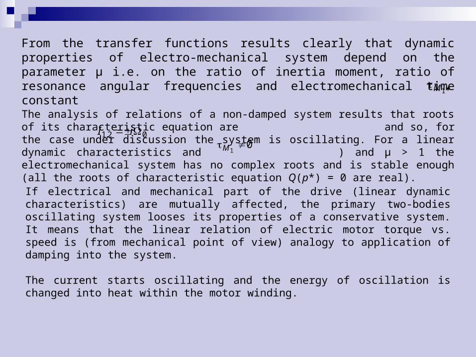
From the transfer functions results clearly that dynamic properties of electro-mechanical system depend on the parameter μ i.e. on the ratio of inertia moment, ratio of resonance angular frequencies and electromechanical time constant
021 iI ,0
1M
The analysis of relations of a non-damped system results that roots of its characteristic equation are and so, for the case under discussion the system is oscillating. For a linear dynamic characteristics and ) and μ > 1 the electromechanical system has no complex roots and is stable enough (all the roots of characteristic equation Q(p*) = 0 are real).
If electrical and mechanical part of the drive (linear dynamic characteristics) are mutually affected, the primary two-bodies oscillating system looses its properties of a conservative system. It means that the linear relation of electric motor torque vs. speed is (from mechanical point of view) analogy to application of damping into the system. The current starts oscillating and the energy of oscillation is changed into heat within the motor winding.
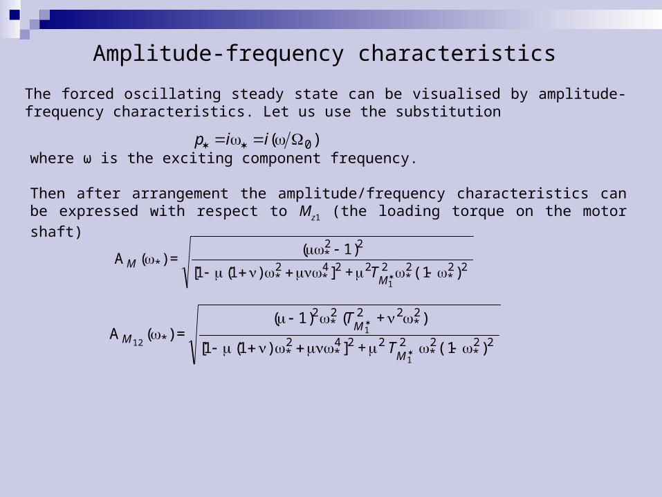
Amplitude-frequency characteristics
The forced oscillating steady state can be visualised by amplitude-frequency characteristics. Let us use the substitution
)( 0 iip
where ω is the exciting component frequency.
Then after arrangement the amplitude/frequency characteristics can be expressed with respect to Mz1 (the loading torque on the motor shaft)
)(1 +] )( [
)+( 1)(=)(A
2****
*2
*2
*
1
1
12 2222242
222
11
M
MM
T
T
)(1+] )( [
1)(=)(A
2****
2*
*
1
2222242
2
11
M
MT

s.0201M s.10e
The amplitude-frequency characteristics for
and 0 is equal to 21,0 or 31,4, or 62,8 rad/s= 10;
0 10 20 30 40 50 60 70 800
1
2
3
4
5
6
7 A
M12
= f()
AM
= f()
AM
12max
=22
32
1
[s-1]
Am
plit
ud
e
Amplitude-frequency characteristics
1- Ω0 = 21 rad/s; 2 - Ω0 = 31.4 rad/s; 3 - Ω0 = 62.4 rad/s
s.10e
ped
1
It follows from the Figure that for great enough value of electromagnetic constant
e
and frequencies close to Ω0 a step resonant
increase of amplitudes occurs and the amplitude value increases with the Ω0. This
feature can be explained by attenuated electro-mechanical coupling by increased frequency at the given , as can be seen from the dynamic stiffness of the characteristics

The frequency is inversely proportional to mechanical stiffness of characteristics and the phase shift with depressing influence on torque component corresponding to viscous damping is manifested. Also, there are lower motor speed amplitudes at higher frequencies. Due to all these facts, the amplitude of elastic coupling torque increases with the increased Ω0, while
amplitudes of driving torque and motor armature current in the resonance area keep their values.This is a case where the main role is played by the electromagnetic time constant e. For e= 0 s all the resonance phenomenae disappear (Fig) due to the increased damping.
0 10 20 30 40 50 60 70 800
1
2 A
M12
= f() A
M = f()
2 1
[s-1]
Am
plitu
de

Resonant phenomenae in machine aggregate with gearing
A machine aggregate is a dynamic system consisting as a rule from a driving machine gearing (reducing) mechanism with its binding, controlling and commanding accessories and a driven plant. The system characteristics, as well as characteristics of the individual subsystems are a result of their mutual accouplement and interference during operational activity. The system characteristics depend not only on the subsystems’ initial characteristics, on their depreciation and overall status within the relevant time, but mainly on external phenomenon valid for the operating time of the system.
From point of gearing a lot of factors influence on the dynamics of the machine aggregate. The internal ones are mainly the choice of gearing basic parameters, material, production technology, accuracy of toothing and gearing clearance, but deformations, production accuracy, wear and working environment. Non-linear electromechanical system consisting from direct-current motor and mechanical gearbox with gearing clearance is solved.
The analysis shows, that after taking kinematic and geometric inaccuracies into consideration, a gear ratio becomes a variable of displacement angle with the frequency proportional to the motor speed. A parametric excitation in elastic systems is caused by this and a rise of dynamic load of the machine aggregate too. Presence of a clearance and a possible transients described in demand for cases of small deviations from a point of static balance to create much more precise linear models.

Mechanical and mathematical models
A mathematical model allows to study steady state and resonant phenomena in an electromechanical dynamical system consisting of an independently excited DC electric motor and a gearing, considering the same gear ratio and gearing clearance.
ur
+
-
I1
Mz
I2
i = 1+i(2)
2
2
k12
1
Md
a)
~
M12
3
t
u2
u1
0
b)
Dynamical models of machine aggregate with gearinga) electromechanical system, b) dependence M12 = F()

Motion model of the system is described by motion equations of the mechanical subsystem
,d
d)(
,d
d
tTMM
tTMMM
Mz
Mzd
212
1121
1
1
1
and by a dynamic torque equation of the electric motor
),(d
d10 d
de M
t
M
ω1, ω2 - mechanical angular speeds of the electromotor rotor (driving shaft) and the driven shaft, φ1, φ2 - angular displacement of the shafts,Ω0 - angular no load speed of the electromotor (of the driving shaft)M12 - elastic coupling torque, Md - driving (internal) electromagnetic torque generated by the rotor of the electric motor,Mz - load torque,Mz - friction torque, - static characteristic stiffness coefficient,k12 - stiffness of elastic coupling, e - DC electromotor electromagnetic time constant,TM1 = I1/β - electromechanic time constant of the driving shaft, μ = (I1 + I2)/I1 - ratio of total reduced (torque of) inertia to driving shaft inertia (DC motor rotor +
tightly coupled parts),I1, I2 - reduced inertia of the driving and driven shaft.

21 t sinmax22
In this case the elastic coupling torque M12 is a non-linear function F(Δφ) of difference of
angular displacement , where . Supposing μ > 5 all the dynamic processes are close to the one-mass system process and 2 = const., mass of the plant (loading mechanism) has no influence to system oscillation.
Amlitude-frequency characteristics
To analyse a steady state motion of the forced oscillation we shall suppose that Δφ on the non/linear element input is changed sinusoidally with exciting frequency and has constant component equal to average load torque. Block diagram of the machine aggregate is shown in following figure.

The motion equation in the Laplace transform has the following form
),()()()()()( ppIpIpMFppppIpI eee 23
12
12
13
1 1
ttp sin)()( max22
max
2
r
r
R
cuM
re RL
tp dd
- excitation induced by the difference of angular
deviation in gearing,
- maximal difference of angular deviation, - frequency of change of angular deviation,
- average value of the load torque,
- electromagnetic time constant of the driving DC motor,L - magnetic induction of DC motor armature,ur - DC motor armature (rotor) supply voltage,
Rr - total resistance of the DC motor armature circuit,
c = k - DC motor constant, - magnetic flux in the DC motor,
- differential operator, Laplace operator.
To analyse a steady state motion of the forced oscillation we shall suppose that Δφ on the non-linear element input is changed sinusoidally with exciting frequency and has constant component equal to average load torque. The solution is supposed to be in the form
~sin 00 tA
A - amplitude of periodic component of angular deviation,
~ - periodic component of angular deviation.

The non-linear function F(Δφ) is replaced by an approximation from the harmonic linearization
~),,(),,()( AqAqF 100
where q0, q1 are coefficients of the harmonic linearization. For u = ωt we have a form
,arcsin)sin(),(A
kk
A
AkduuAkAq
u
u
00120
122
01201200 2
12
1 2
1
.arcsinsin)sin(),(2
00120121201201 1
2
1 2
1
AA
k
A
kkuduuAk
AAq
u
u
The solution after substitution of the function F(Δφ) can be written in a form of two equations for the constant and the periodical component
MA
kk
A
Ak 00120122
012
21 arcsin
),()()(~arcsin)()(~)( ppIpIppAA
k
A
kkppppIpI eee 2
31
21
20012012122
13
1 12
1

In a non-dimensional form
M
AA
A 000
2
0
21 arcsin
),(~
)(~
pMpppT
pMqpT
qpp e
MMe
e
3
20
220
20
1220
220
320
1111
11
where
- ratio of first harmonic of elastic coupling torque and the base moment Mb
2
000 11
2
1
AAAq arcsin
bM
tkM
)(~~
1212
,sinsin)(
maxmax tMt
M
k
M
tkM
bb
12212
max~
1212
MA
M
AkA
bb
b 00
12kMbb
21
21120 II
IIk )(
- amplitude of the periodical component in the non-dimensional form,
- constant component of solution,
- basic angular displacement,
- natural angular velocity,

For analysis of the system steady state motion with clearance we obtain
2
220
2224
4220
2
12
1
112
1
1
Mee
Mee
M
TMAqMAq
T
M
MA
),()),((
~
max
max
where 0 - frequency ratio.
From this results that in the nonlinear system under consideration the vibration amplitudes at given excitation frequency depend not only on excitation ΔM* but also on the average value of the load M*Φ.

In the Fig. can be seen that non-linearity caused by gearing clearance results in a considerable deformation of the resonance curve and the resonance is manifested already in lower frequencies than the resonance frequency and shows an ambiguity of disturbances amplitude. Also, a specific property of a system with clearance, a dependence on the M*Φ can be seen.
The curve No.3, presents an amplitude-frequency characteristics of a linear system. At a given speed of the electric motor, greater than zero, both frequency ω and the corresponding variable component of gear load increase. If the variable component is less than the average value of gear load, impact of clearance is not manifested (it is closed) and the system plays to be linear.
For M*Φ = 0.2 (curve 1) in the point K stability occurs, i.e. A* = M*Φ. If the amplitude keeps increasing, the clearance becomes open. Due to this fact the harmonic linearized stiffness decreases and the area of resonance is shifted to the point K.
Consequently, the amplitude for the same frequency increases, coefficient of harmonic linearization decreases again - it means that an avalanche increase of amplitude to the point L, curve 1 is generated. Balance is reached in the point L again.
For decreasing frequency ω the amplitude grows up to point M, where the maximal amplitude at given frequency, i.e. A* = f(q) is less than q = f(A*) at M*Φ = 0.2. Conditions for creation of resonance are corrupted and values of amplitude fall down below values given by the curve 3.
Results and analysis of results

0,7 0,8 0,9 1,0 1,1 1,2 1,3 1,4 1,5 1,60,0
0,1
0,2
0,3
0,4
0,5
0,6
0,7
0,8
0,9
1,0
1,1
1,2
1,3
3'''
3''
3'
3
2'
2''
2
1
A*
0,2 0,4 0,6 0,8 1,0 1,2 1,40
1
2
3
4
5
3
2
L
K
1
M
A*
Amplitude-frequency characteristics a) low damping system with gearing clearance, b) high damping system with clearance

Increase of the average load value brings about an increase of amplitude too (Fig. - curve 2) and the character of deformation is the same as in the previous case. From the Fig. can also be seen that in the zone of linear resonance the non-linearity caused by gearing clearance limits vibration amplitude values to values close to average load value, but expands the zone of resonance vibrations to the lover frequencies more than the average load.The influence of damping effect from the electrical drive to the steady state motion in the system with a clearance are given by curves 1, 2, 3 in the Fig., for a linear system with ω0 = 22 rad/s and the time constants e , TM1 as follows:
The damping for parameters corresponding to the curve 3 is attenuated, hence the calculated relations A* = f(h) for ΔM*max = 0.15 and M*Ф = 0.1 (curve 3’) or M*Ф = 0.4 (curve 3’’), or M*Ф = 1.0 (curve 3’’’) have lower amplitudes.Higher damping cause not only lower amplitudes, but also decreases of non-linear resonance (curve 2’ for M*Ф = 0.1 and curve 2’’ for M*Ф = 0.4). For the maximal damping value curves of non-linear resonance are in fact associated with the characteristics of a linear system (curve 1). Choice of optimal parameters for a linear system minimizes the possibility of vibration in the system with gearing clearance.

The method of harmonic linearization is an effective mean to analyze physical peculiarities of steady state vibrating processes in nonlinear electromechanical systems considering the real conditions for the system motion with variable gear ratio and a clearance. Using the method of harmonic linearization it is to respect the fact that it only gives result close to the reality.If the characteristic equation for (3) has the form of
0 )()()()( FpRppQ
formulation of conditions characterizing the accuracy of the method is as follows:
1. The rate of polynomial R(p) must be lower than the rate of polynomial Q(p),2. The polynomial Q(p) must have neither complex conjugate roots nor positive real roots, the relation q(A) must be smooth.
The harmonic linearization allows to explain character of processes and physical properties of a nonlinear subject. Quantitative differences in computation of resonance amplitudes rated 30-40% can be explained by specific effects of internal excitations (disturbance) caused by pulsating gear ratio. There is derived considering the exciting torque to influence the rotor of the DC electric motor and at the origin of clearance is interrupted. This fact decreases the precision of quantitative evaluations, but allows to solve successfully tasks of properties analysis in nonlinear electromechanical systems.