mechanized continuous drawing systems massmin2008
TRANSCRIPT
0HFKDQL]HG� &RQWLQXRXV� 'UDZLQJ� 6\VWHP�� $� WHFKQLFDO� DQVZHU� WR�LQFUHDVH�SURGXFWLRQ�FDSDFLW\�IRU�ODUJH�%ORFN�&DYLQJ�0LQHV���9��(QFLQD��,QVWLWXWR�GH�,QQRYDFLRQ�HQ�0LQHLtD�\�0HWDOXUJLD�,0��6�$���&KLOH�)��%DH]��&RGHOFR�&KLOH��&KLOH�)��*HLVWHU�&RGHOFR�&KLOH��&KLOH�-��6WHLQEHUJ��'HXWVFKH�%HUJEDX�7HFKQLN��'%7��*HUPDQ\���$EVWUDFW�&XUUHQWO\��QHDU���������WRQV�SHU�GD\�DUH�PLQHG�IURP�(O�7HQLHQWH��$QGLQD�DQG�6DOYDGRU�XQGHUJURXQG�PLQHV�RI�&RGHOFR�&KLOH��$OO�RI�WKHP�SODFHG�RQ�KDUG�URFN�XWLOL]LQJ�µEORFN�FDYLQJ�PHWKRG¶��%\�WKH�PLGGOH�RI�WKH�QH[W�GHFDGH��(O�7HQLHQWH�DQG�$QGLQD�PLQHV�ZLOO�EH�SODFHG�DW�GHHSHU�DQG�KDUGHU�URFN��6DOYDGRU�PLQH�ZLOO� EH� FORVHG�� EXW� UHSODFHG� E\� &KXTXLFDPDWD�8QGHUJURXQG�PLQH��&KXTXLFDPDWD�PLQH� LV�FXUUHQWO\� RQH� RI� WKH� ODUJHVW� RSHQ� SLW� PLQHV� LQ� WKH� ZRUOG� WKDW� KDYH� WR� EH� FRQYHUWHG� WR� XQGHUJURXQG�� ,Q�DGGLWLRQ�WR�WKLV�UHOHYDQW�FKDOOHQJH��WKH�&RPSDQ\�UHTXLUHV�WR�LQFUHDVH�WKH�XQGHUJURXQG�SURGXFWLRQ�WR�UHDFK�QHDU���������WRQV�SHU�GD\��7KLV�SDSHU�GHVFULEHV�WKH�WHFKQLFDO�DQVZHU�JRW�E\�&RGHOFR�&KLOH�WR�DFKLHYH�WKLV�WDUJHW��$�GUDPDWLF�LQFUHDVH�RI�H[WUDFWLRQ¶V�UDWH� LV�H[SHFWHG�E\�PHDQV�RI�D�QHZ�ZD\�RI�GUDZLQJ� WKH�FDYHG�RUH�ZLWK�D� IXOO\�PHFKDQL]HG�FRQWLQXRXV�GUDZLQJ�V\VWHP�DW�WKH�SURGXFWLRQ�OHYHO��7KH�0HFKDQL]HG�&RQWLQXRXV�'UDZLQJ�6\VWHP��0&'6��FRQVLVWV�RI�D�VHW�RI�VWDWLRQDU\�IHHGHUV�ORFDWHG�LQ�GUDZ�SRLQWV��ZKLFK�IHHGV�D�FRQWLQXRXV�FRQYH\RU�HTXLSSHG�ZLWK�D�FUXVKHU�LQ�RUGHU�WR�UHGXFH�WKH�VL]H�RI�PDWHULDO��$OO� WKLV� HTXLSPHQWV� DUH� ORFDWHG� DW� WKH� SURGXFWLRQ� OHYHO�� ZKHUH� DQG� HQGLQJ� SURGXFW� LV� REWDLQHG� WR� EH�WUDQVSRUWHG�WR�VXUIDFH��7KH� GHVFULSWLRQ� LQFOXGHV� WKH� GHVLJQ� DQG�PLQH� SODQQLQJ� LVVXHV� RI� WKH� QHZ�PHWKRG� GHYHORSHG� E\� ,0�� DQG�&RGHOFR�� WKH� VSHFLDO� HTXLSPHQWV� DUUDQJHPHQW� GHYHORSHG� E\� 'HXWVFKH� %HUJEDX� 7HFKQLN�� '%7� DQG� WKH�LQGXVWULDO�WHVWV�SHUIRUPHG�E\�,0��DQG�&RGHOFR���
�� ,QWURGXFWLRQ�Codelco Chile Company is a state company, with the mission of exploiting the ore resources of several mines nationalized by the Chilean government in 1972. After 35 years, the ore reserves are placed in harder rock and near 500m deeper than those days of nationalization. Also, the evolution of the company has raised the production up 1.8 million tons of copper per year. Currently, 40% of that production is coming from three underground mines of sulphides ore of Copper.
Dairy production of mineral in the underground mines, expressed in thousand of tons per day (ktpd), are currently of 120, 47 and 33 ktpd from El Teniente, Andina and Salvador mines respectively. All of them exploited by Panel Caving. The rest of fine copper production comes from open pit mines. Among them, the largest one is Chuquicamata mine contributing with 180 ktpd of sulphides ore.
Chuquicamata open pit has to be converted to underground when getting close 1000m deep. This could be happening approximately in years 2015 to 2018. Near that time, Codelco Chile Company’s Development Plan considers raising the underground production from 200 to 500 ktpd.
A simple analysis of potential production of those mines with the current technology of material handling, mainly based on LHD equipment, leads to the conclusion that it is not possible to get such level of
production. It could reasonably reach 360 ktpd equally with the distribution of 120 ktpd each, coming from the three mines: El Teniente, Andina and Chuquicamata underground. Considering this, last ten years an intensive program of research for technological development has been performed by IM21, focused on increase 50% the rate of extraction in underground mines to satisfy the demand of the Development Plan.
The answer is a new full mechanized material handling system trying to get the extraction from more than one drawpoint at a time. For that purpose, a special stationary feeder was developed for drawing the material as well as feed a continuous conveying system that includes a low profile crushing equipment. The whole system of material handling is called Mechanized Continuous Drawing System (MCDS).
�� &RQFHSW�In block/panel caving, the fragmentation process is made by spreading the caving of a surface undermined. It starts with an undercut and continues by extracting the caved material trough the drawpoints. The amount of material drawn during this stage depends on the “ability” of the ground to collapse and convert itself from a continuous solid mass into a confined stock of coarse granular material; this means that a swelling effect has to occur such a way that the broken material occupies the same volume as the solid mass. During this stage, the extraction rate may be called Spread Rate of Extraction ( s), which is restricted to low values in order to avoid the risk of piston effect2 and to avoid high magnitude in seismic events.
After the complete spread of caving is reached, the whole column of solid mass remains converted in a big confined pile of coarse granular material. In such condition it is possible to extract the ore without restrictions except the capacity of extraction of the material handling system. During this stage the extraction UDWH�PD\�EH�FDOOHG�5HDSLQJ�5DWH�RI�([WUDFWLRQ�� r).
Spread and Reaping rates of extraction are expressed in tpd per m2 of active area. To get a constant rate of production from the mine, it is required that each time that a block becomes exhausted, another has to be ready to be reaped. Therefore, the time took to spread one blocks has to be at most equal to the time of reaping another one. Then the following equation3 can be set:
�� ��� s � (1 -� ����� r or: r � s * (1- � �� � Where:
� �)UDFWLRQ�RI�YROXPH�RI�RUH�H[WUDFWHG�WR�VZHOO�WKH�EURNHQ�PDWHULDO�LQ�WKH�EORFN
In conventional LHD block/banel cDYLQJ�RSHUDWLRQV��WKLV�HTXDWLRQ�LV�QRW�D�PDWWHU�RI�GLVFXVVLRQ���EHFDXVH� s is less than 0.4 tpd/m2 and � LV� LQ� WKH� UDQJH� RI� ����� WR� ������ 7KHQ� r has to be less than 1.2 or 0.8 tpd/m2
respectively, which are quite the maximum achievable with the LHD. So, the balance between spreading and reaping blocks is close to 1:1 and it appears as something ‘natural’.
A different thing can be seen when the target is to increase the reaping rate of extraction. The first problem to solve is how to balance the spreading and reaping areas to get a constant output of production. The solution is to have more than one block in spreading phase working in tandem. In this case the reaping time has to be a proper fraction of the time taken in spreading a block. This means that the previous equation can be generalized as follows:
��� s = n * (1 -� ����� r or: r = n * s * (1- � �� � (1)
Where “n” is the amount of blocks in spreading phase and one nth of the spreading time equals the reaping time.
2Q� WKH� RWKHU� KDQG�� WKH�0HDQ�5DWH� RI� ([WUDFWLRQ� � m) expressed in tpd per m2 of active area (active area includes both the spread and the reaping areas) is given by:
1 the Codelco Chile’s Institute for Innovation in Mining and Metallurgy, 2 When more material than the caving can provide is extracted: a void of air takes place in the stope. If that is the case and the roof
collapses; it causes the volume of air from the stope is violently expulsed throughout the production level. 3 Note that if r > s * (1-
� � ��� ����� � ����� ����� ������� � � ��������� � � ��� � ! � "#���$������� �������%� !�� &��('�� ��� )
m = (n * s + r) / (n+1) (2)
Then: replacing (1) on (2):
m = ( s �� �� ��Q����Q���� (3)
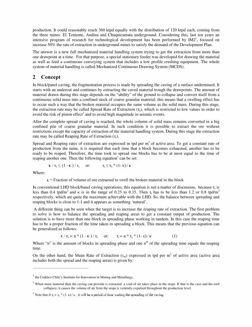
(TXDWLRQ�����VD\V�WKDW� m�LV�DV\PSWRWLF�WR� s / ���DV�LW�LV�Sresented in )LJXUH���*,+.-0/.1325406�17-58:9<;.=$>?-7@ =$A 2�8:B -%= 1
0%
10%
20%
30%
40%
50%
60%
70%
80%
90%
100%
1 2 3 4 5 6 7 8 9 10 11 12 13 14 15 16 17 18 19 20C
D EF GHIJKL ELM NOGP QR
�)LJXUH���� 6KDSH�RI�WKH�FXUYH��0HDQ�([WUDFWLRQ�5DWH�YV��Q�
In fact, if n=1, the time taken for the extraction of the swelling volume is the same as the time to extract the VZHOOHG�PDWHULDO��LQ�WKDW�FDVH�� m�ZLOO�EH�RQO\�RQH�KDOI�RI� s / ��� From the graphic, it is clear that when n����WKH�HIIHFW�RQ� m is not relevant compared with the effort of having more blocks in spreading phase.
Taking common values for: � ������DQG� s = 0.30 tpd/m2; the maximum value for m is 1.0 tpd/m2. Table 1, shows the r required to achieve the corresponding m for different values of n.
7DEOH��� 0HDQ�DQG�5HDSLQJ�([WUDFWLRQ�5DWH�YV��Q�n Mean Extraction Rate
m [tpd/m2] Reaping Extraction 5DWH� r [tpd/m2]
1 0,50 0,70
2 0,67 1,40
3 0,75 2,10
4 0,80 2,80
� 1.00
Therefore, to increase 50% the Mean Rate of Extraction (e.g. from 0.5 to 0.75 tpd/m2) it is required to increase 200% of Reaping Extraction Rate (3 times: e.g. from 0.70 to 2.10 tpd/m2).
With the conventional LHD system is practically impossible to reach that figures of reaping extraction rate, mainly because in that system less than 10% of the active area is actually in use for production. In fact, in
any production drift there are 10 to 20 drawpoints available to produce, but the loader can only extract the ore from one at a time.
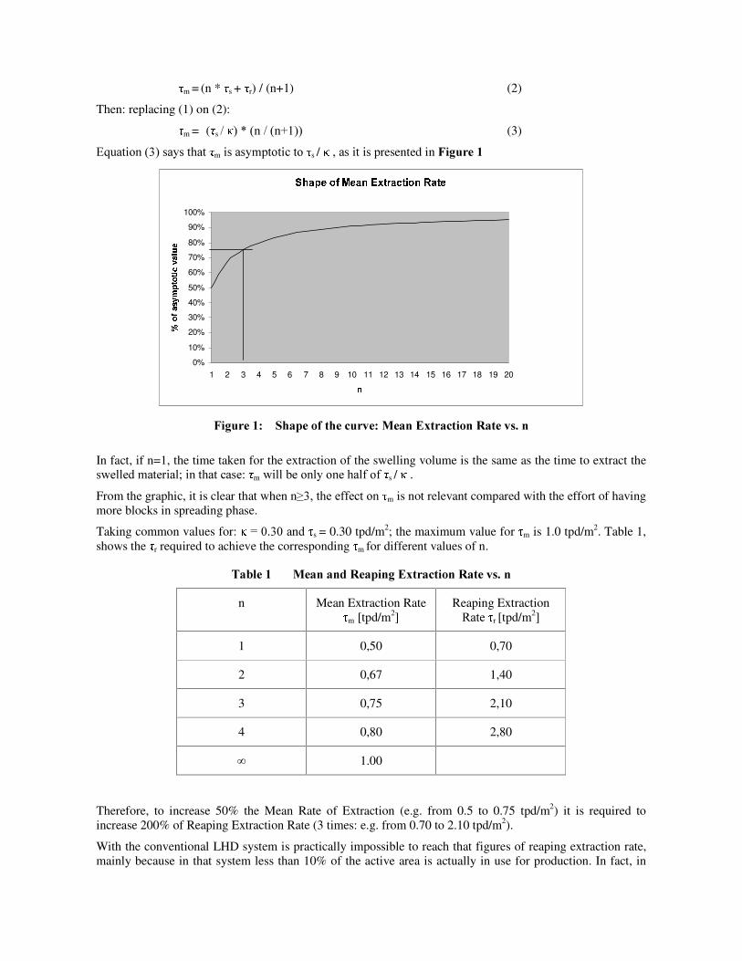
One way to increase the use of active area could be the installation of stationary feeders in the drawpoints. The feeders would feed a gathering conveyor placed on the floor of the production drift. In this way, more than one drawpoint could work at the same time and a significant increase in the reaping rate of extraction may be obtained.
Looking for the convenience of continuous transport, early crushing was introduced to size de material for making it compatible with belt conveyors and for avoiding grizzlies on ore passes. A very simple arrangement of the Mechanized Continuous Drawing System (MCDS) was prepared as indicated on )LJXUH��
.
SUT�V W�X Y�T[Z%V X \ ]
^ V _U`�aUY�] X _�b[Z7V X \ ]
Z%V c�dfegT�h h i
Z�_Uj�T�V7k�T�TU`gT�V
l�mUc�X b�l�_�b�WUT�n�_�V
o _�h h�l�V agi�mUT�V
)LJXUH���� 6FKHPH�RI�([WUDFWLRQ�/HYHO�
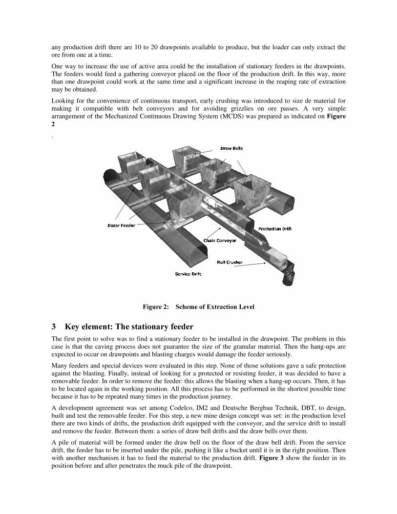
�� .H\�HOHPHQW��7KH�VWDWLRQDU\�IHHGHU�The first point to solve was to find a stationary feeder to be installed in the drawpoint. The problem in this case is that the caving process does not guarantee the size of the granular material. Then the hang-ups are expected to occur on drawpoints and blasting charges would damage the feeder seriously.
Many feeders and special devices were evaluated in this step. None of those solutions gave a safe protection against the blasting. Finally, instead of looking for a protected or resisting feeder, it was decided to have a removable feeder. In order to remove the feeder: this allows the blasting when a hang-up occurs. Then, it has to be located again in the working position. All this process has to be performed in the shortest possible time because it has to be repeated many times in the production journey.
A development agreement was set among Codelco, IM2 and Deutsche Bergbau Technik, DBT, to design, built and test the removable feeder. For this step, a new mine design concept was set: in the production level there are two kinds of drifts, the production drift equipped with the conveyor, and the service drift to install and remove the feeder. Between them: a series of draw bell drifts and the draw bells over them.
A pile of material will be formed under the draw bell on the floor of the draw bell drift. From the service drift, the feeder has to be inserted under the pile, pushing it like a bucket until it is in the right position. Then with another mechanism it has to feed the material to the production drift.�)LJXUH���show the feeder in its position before and after penetrates the muck pile of the drawpoint.
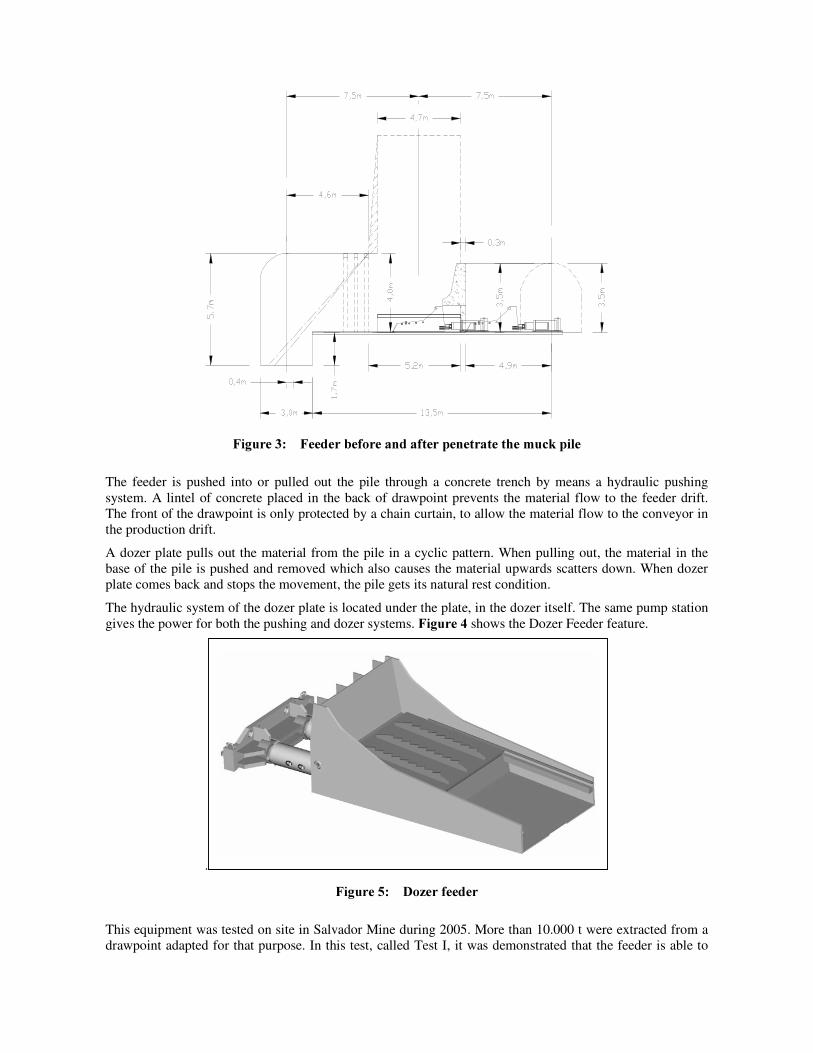
)LJXUH���� )HHGHU�EHIRUH�DQG�DIWHU�SHQHWUDWH�WKH�PXFN�SLOH�
The feeder is pushed into or pulled out the pile through a concrete trench by means a hydraulic pushing system. A lintel of concrete placed in the back of drawpoint prevents the material flow to the feeder drift. The front of the drawpoint is only protected by a chain curtain, to allow the material flow to the conveyor in the production drift.
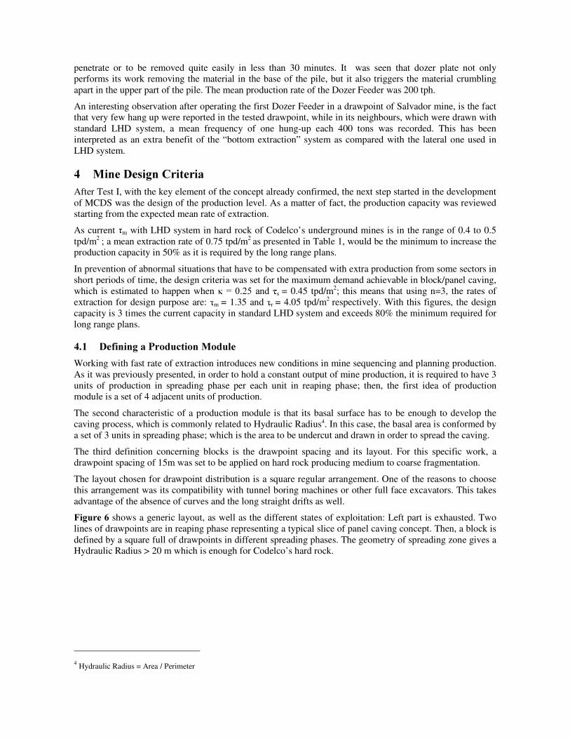
A dozer plate pulls out the material from the pile in a cyclic pattern. When pulling out, the material in the base of the pile is pushed and removed which also causes the material upwards scatters down. When dozer plate comes back and stops the movement, the pile gets its natural rest condition.
The hydraulic system of the dozer plate is located under the plate, in the dozer itself. The same pump station gives the power for both the pushing and dozer systems. )LJXUH�� shows the Dozer Feeder feature.
.
)LJXUH���� 'R]HU�IHHGHU�
This equipment was tested on site in Salvador Mine during 2005. More than 10.000 t were extracted from a drawpoint adapted for that purpose. In this test, called Test I, it was demonstrated that the feeder is able to
penetrate or to be removed quite easily in less than 30 minutes. It was seen that dozer plate not only performs its work removing the material in the base of the pile, but it also triggers the material crumbling apart in the upper part of the pile. The mean production rate of the Dozer Feeder was 200 tph.
An interesting observation after operating the first Dozer Feeder in a drawpoint of Salvador mine, is the fact that very few hang up were reported in the tested drawpoint, while in its neighbours, which were drawn with standard LHD system, a mean frequency of one hung-up each 400 tons was recorded. This has been interpreted as an extra benefit of the “ bottom extraction” system as compared with the lateral one used in LHD system.
�� 0LQH�'HVLJQ�&ULWHULD�After Test I, with the key element of the concept already confirmed, the next step started in the development of MCDS was the design of the production level. As a matter of fact, the production capacity was reviewed starting from the expected mean rate of extraction.
As current m with LHD system in hard rock of Codelco’s underground mines is in the range of 0.4 to 0.5 tpd/m2 ; a mean extraction rate of 0.75 tpd/m2 as presented in Table 1, would be the minimum to increase the production capacity in 50% as it is required by the long range plans.
In prevention of abnormal situations that have to be compensated with extra production from some sectors in short periods of time, the design criteria was set for the maximum demand achievable in block/panel caving, which is estimated to happen when � ������DQG� s = 0.45 tpd/m2; this means that using n=3, the rates of extraction for design purpose are: m = 1.35 and r = 4.05 tpd/m2 respectively. With this figures, the design capacity is 3 times the current capacity in standard LHD system and exceeds 80% the minimum required for long range plans.
���� 'HILQLQJ�D�3URGXFWLRQ�0RGXOH�Working with fast rate of extraction introduces new conditions in mine sequencing and planning production. As it was previously presented, in order to hold a constant output of mine production, it is required to have 3 units of production in spreading phase per each unit in reaping phase; then, the first idea of production module is a set of 4 adjacent units of production.
The second characteristic of a production module is that its basal surface has to be enough to develop the caving process, which is commonly related to Hydraulic Radius4. In this case, the basal area is conformed by a set of 3 units in spreading phase; which is the area to be undercut and drawn in order to spread the caving.
The third definition concerning blocks is the drawpoint spacing and its layout. For this specific work, a drawpoint spacing of 15m was set to be applied on hard rock producing medium to coarse fragmentation.
The layout chosen for drawpoint distribution is a square regular arrangement. One of the reasons to choose this arrangement was its compatibility with tunnel boring machines or other full face excavators. This takes advantage of the absence of curves and the long straight drifts as well.
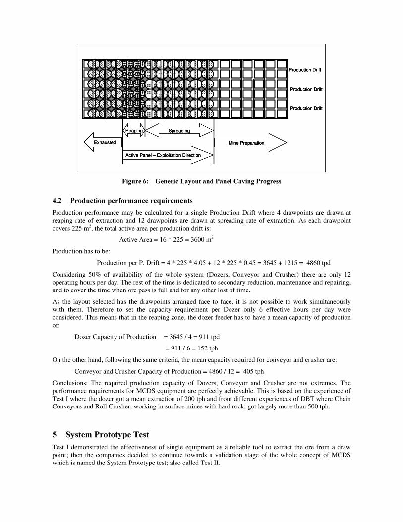
)LJXUH�� shows a generic layout, as well as the different states of exploitation: Left part is exhausted. Two lines of drawpoints are in reaping phase representing a typical slice of panel caving concept. Then, a block is defined by a square full of drawpoints in different spreading phases. The geometry of spreading zone gives a Hydraulic Radius > 20 m which is enough for Codelco’s hard rock.
4 Hydraulic Radius = Area / Perimeter
Exhausted
Reaping Spreading
Mine Preparation
Production Drift
Production Drift
Production Drift
Active Panel – Exploitation Direction
Exhausted
Reaping Spreading
Mine Preparation
Production Drift
Production Drift
Production Drift
Active Panel – Exploitation Direction
Exhausted
Reaping Spreading
Mine Preparation
Production Drift
Production Drift
Production Drift
Active Panel – Exploitation Direction
)LJXUH���� *HQHULF�/D\RXW�DQG�3DQHO�&DYLQJ�3URJUHVV�
���� 3URGXFWLRQ�SHUIRUPDQFH�UHTXLUHPHQWV�Production performance may be calculated for a single Production Drift where 4 drawpoints are drawn at reaping rate of extraction and 12 drawpoints are drawn at spreading rate of extraction. As each drawpoint covers 225 m2, the total active area per production drift is:
Active Area = 16 * 225 = 3600 m2
Production has to be:
Production per P. Drift = 4 * 225 * 4.05 + 12 * 225 * 0.45 = 3645 + 1215 = 4860 tpd
Considering 50% of availability of the whole system (Dozers, Conveyor and Crusher) there are only 12 operating hours per day. The rest of the time is dedicated to secondary reduction, maintenance and repairing, and to cover the time when ore pass is full and for any other lost of time.
As the layout selected has the drawpoints arranged face to face, it is not possible to work simultaneously with them. Therefore to set the capacity requirement per Dozer only 6 effective hours per day were considered. This means that in the reaping zone, the dozer feeder has to have a mean capacity of production of:
Dozer Capacity of Production = 3645 / 4 = 911 tpd
= 911 / 6 = 152 tph
On the other hand, following the same criteria, the mean capacity required for conveyor and crusher are:
Conveyor and Crusher Capacity of Production = 4860 / 12 = 405 tph
Conclusions: The required production capacity of Dozers, Conveyor and Crusher are not extremes. The performance requirements for MCDS equipment are perfectly achievable. This is based on the experience of Test I where the dozer got a mean extraction of 200 tph and from different experiences of DBT where Chain Conveyors and Roll Crusher, working in surface mines with hard rock, got largely more than 500 tph.
�� 6\VWHP�3URWRW\SH�7HVW�Test I demonstrated the effectiveness of single equipment as a reliable tool to extract the ore from a draw point; then the companies decided to continue towards a validation stage of the whole concept of MCDS which is named the System Prototype test; also called Test II.
Building and installing the equipment on site by Codelco’ s Salvador Division, took from 2006 to March 2007, included engineering, contracting, building and assembling of the test mine site. On the other hand equipment supplying and assembling were supported by DBT.
From March to November 2007 drilling and blasting the undercut were performed to connect the test site to old caved zones. Test II started properly on December 2007.
Test II is conceived to get the final industrial and commercial design features of MCDS. For that purpose a special test site was prepared to check the system composed by 4 drawpoint equipped with dozer feeders feeding the ore to: a chain conveyor (Panzer), a Roll Impact Crusher and a belt conveyor.
System Prototype Test is a unique opportunity to collect valuable information to be considered in the engineering and designing of the final components of MCDS. Then, complementary data was planned to get more knowledge about draw strategy; assembly, secondary reduction and maintenance best practices, dust and noise conditions and functionality or reliability of special devices for automation and/or process control.
���� 7HVW�6LWH��5.1.1 /RFDWLRQ
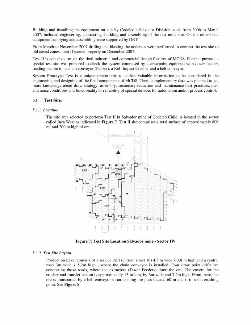
The site area selected to perform Test II in Salvador mine of Codelco Chile, is located in the sector called Inca West as indicated in )LJXUH��. Test II site comprises a total surface of approximately 800 m2 and 200 m high of ore.
2007
2008
2009
2010
20082007
)LJXUH����7HVW�6LWH�/RFDWLRQ�6DOYDGRU�PLQH���6HFWRU�,:�
5.1.2 7HVW�6LWH�/D\RXW Production Level consists of a service drift (current street 16) 4,3 m wide x 3,8 m high and a central road 3m wide x 5,2m high , where the chain conveyor is installed. Four draw point drifts are connecting those roads, where the extractors (Dozer Feeders) draw the ore. The cavern for the crusher and transfer station is approximately 13 m long by 6m wide and 7,2m high. From there, the ore is transported by a belt conveyor to an existing ore pass located 60 m apart from the crushing point. See )LJXUH��.
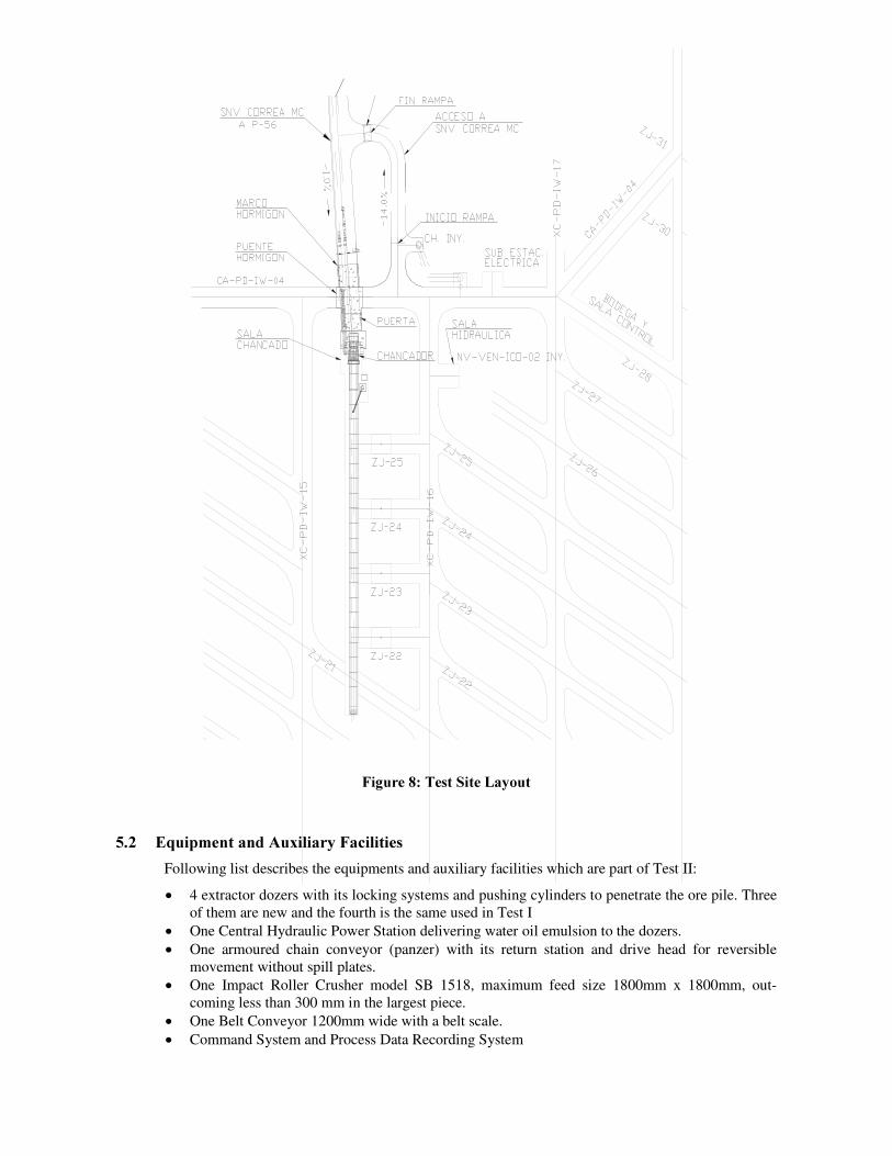
)LJXUH����7HVW�6LWH�/D\RXW��
���� (TXLSPHQW�DQG�$X[LOLDU\�)DFLOLWLHV�Following list describes the equipments and auxiliary facilities which are part of Test II:
x� 4 extractor dozers with its locking systems and pushing cylinders to penetrate the ore pile. Three of them are new and the fourth is the same used in Test I
x� One Central Hydraulic Power Station delivering water oil emulsion to the dozers. x� One armoured chain conveyor (panzer) with its return station and drive head for reversible
movement without spill plates. x� One Impact Roller Crusher model SB 1518, maximum feed size 1800mm x 1800mm, out-
coming less than 300 mm in the largest piece. x� One Belt Conveyor 1200mm wide with a belt scale. x� Command System and Process Data Recording System

x� Dedicated Electrical Power Substation
���� 7HVW�3URFHGXUH�A dedicated crew of workers has been assigned by Salvador Division to perform the test. The entire test is conducted and supervised by IM2 Field Engineers and assisted by Service Engineer of DBT.
5.3.1 7HVW�5HFRUGLQJ
All data are saved in the central command computer of the control room including time and current in motors, pressure in pumps and cylinders and tonnage in the belt scale. Data recording allows a reconstruction of the history of operation conditions and studying every minute of operation.
To complete the evaluation of Test II, also the following data are being recorded too:
• All consumables used for operation. • Operating, no operating and maintenance time records and its causes, concerning with all
particular equipment in the system. • Wearing control specially in wearing pieces of dozer feeder, chain conveyor and crusher. • Video record of transport of pieces through underground tunnels and in the test site. • Power consumption in pumps, chain conveyor, crusher and belt conveyor. • All labour time occupied to perform Test II and all the expenses incurred during it.
���� 3DUWLDO�5HVXOWV�5HSRUWV�Test II considers the extraction of 200.000 tons, 50.000 tons per drawpoint. After that, the evaluation of the system can be done. As the test is still running there are no definitive results, but partial figures give a good prognosis.
From December 2007 to February 2008, 19.049 tons has been extracted, almost 10 % of the test tonnage. In this short period, all components of MCDS are performing much better than expected, but it is very early to get definitive conclusions. Final results will be available at the end of 2008.
�� $FNQRZOHGJHPHQWV�Special posthumous acknowledgements to Reinhold Brügemann, for his invaluable contribution in designing and manufacturing the first Dozer Feeder and for the whole concept of MCDS. Also, to the executives of the companies holding this initiative Codelco Chile, IM2 and DBT; for their commitment and conviction to go ahead in this technological adventure. Finally, to the workers performing the test and making its components. Without their enthusiastic support, the development of this new technology couldn’ t be possible.
�� 5HIHUHQFHV�Carrasco, F., Encina, V., Letelier P., (2005) ‘Design and Testing of Drawpoint Stationary Feeder: Final Report ’ ,
Internal report IM2, Chile. Carrasco, F., Encina, V., Mass, S., 2004 ‘Extraction rate: As an index of effectiveness’ , Chapter 12 -01, Draw
Management. Proceedings MassMin, Chile. Chacón, J., Göepfert, H., Ovalle, A., (2004) ‘Thirty years evolution of block caving in Chile’ , Chapter 10-01 Mass
Mining Methods II: Case History. Proceeding MassMin. Encina, V., Letelier P., (2004) ‘Design of draw points based on experimental observations of gravitational flow of
granular material’ , 55th Convention of Institute of Mining Engineers of Chile, Chile Encina, V., Correa L., 2001 ‘Continuous Mining: Ad portas technological break through ’ , 52th Convention of Institute
of Mining Engineers of Chile, Chile