mechanics of cutting and boring
TRANSCRIPT
SR 226
Spec ia l Report 226
MECHANICS OF CUTTING AND BORING
PART 1: K INEMATICS OF TRANSVERSE ROTATION MACHINES
M a l c o l m M e l l o r
May 1975
GB2401.C6no.2261975
CORPS OF ENGI NEE RS , U.S. ARMY
)LD REGIONS RESEARCH AND ENGINEERING LABORATORYHA N O V E R , NEW HAM PSHIRE
A P P R O V E D F O R P U B L I C R E L E A S E ; D I S T R I B U T I O N U N L I M I T E D .

BUREAU OF RECLAMATION LIBRARY DENVER, CO
The findings in this report are not to be construed as an official Department of the Army position unless so designated by other authorized documents.

r &\ J f > \ ________ Unclassified_______________________
S E C U R IT Y C L A S S IF IC A T IO N O F T H IS P A G E (When D a ta E n tered )0/V BUREAU OF RECLAMATION DENVER LIBRARY
% 44REPORT DOCUMENTATION PAGE , __________ 9 2 0 9 9 6 3 0
1. R E P O R T N U M B E R 2. G O V T A CC ESSIO N NO.
Special Report 2263. R E C IP IE N T 'S C A T A L O G N U M B E R
* . T IT L E (a n d S ubtitt» )
MECHANICS OF CUTTING AND BORINGPart 1: Kinematics of Transverse Rotation Machines
5. T Y P E O F R E P O R T ft P E R IO D C O V E R E D
6. P E R F O R M IN G ORG. R E P O R T N UM B ER
7. A U T H O R ( • )
Malcolm Mellor
8. C O N T R A C T OR G R A N T N U M B E R (a)
9 . P E R F O R M IN G O R G A N IZ A T IO N N A M E AND ADDRESS
U.S. Army Cold Regions Research and Engineering Laboratory Hanover, New Hampshire 03755
10. PROGRAM E L E M E N T , P R O J E C T , TASK A REA ft WORK U N IT NUM BERS
DA Project 4A762719AT30 Task 03, Work Unit 002
11. C O N T R O L L IN G O F F IC E NAM E AND ADDRESS
Office, Chief of Engineers Washington, D.C. 20314
12. R E P O R T D A T E
May 197513. N UM B ER O F PAGES
3314. M O N IT O R IN G A G E N C Y NAM E ft A DD R ESS^// d ifferen t from C on tro llin g O ffice ) 15. S E C U R IT Y CLASS, (o f th is report)
Unclassified15«. d e c l a s s i f i c a t i o n / d o w n g r a d in g
S C H E D U LE
16. D IS T R IB U T IO N S T A T E M E N T (o f th ia R ep o rt)
Approved for public release; distribution unlimited.
17. D IS T R IB U T IO N S T A T E M E N T (o f th e a b s tra c t e n te re d in B lo c k 20 , If d iffe ren t from R eport)
18. S U P P L E M E N T A R Y N O TE S
19. K E Y WORDS (C on tin u e on r e v e r s e s id e i f n e c ea a a ry and id e n tify by b lo c k number)
Excavating machines Permafrost excavation Excavation Rock cutting Ice cutting Machine design
2(L A B S T R A C T (*Can tin u e o n r e v e r s e eitOe f t neceem m ty and. id e n tif y by b lo c k number)
This report, which is one of a series on the mechanics of cutting and boring in rock, deals with the kinematics of machines such as disc saws, drum millers, rotary planers and bucket-wheel excavators, in which the rotary cutting element revolves about an axis that is normal to the direction of working travel. The analysis covers the geometry and motion of various components of the cutting system, touching on topics such as chipping depth, cutting transfer, excavation rate, tool trajectories, tool speeds, rake and relief angles on tools and tool layout. Worked examples are given to illustrate various points.
DD tFORM JAM 73 1473 E D IT IO N O F 1 N O V 6 5 IS O B S O L E T E Unclassified
S E C U R IT Y C L A S S IF IC A T IO N O F T H IS P A G E (When D ata E n tered)
92099630

ii
PREFACE
This report was prepared by Dr. Malcolm Mellor, Research Civil Engineer, Applied Research Branch, Experimental Engineering Division, U.S. Army Cold Regions Research and Engineering Laboratory. The work was done under DA Project 4A762719AT30, Research for Protective Structures in Theaters o f Operations, Task 03, Protective Structures for Winter Conditions, Work Unit 002, Cut ting, Drilling and Excavating Frozen Materials.
The writer is grateful to Paul V. Sellmann for numerous discussions on the intricacies of tool motion. He is also indebted to a number of machine operators for practical explanations of various problems and working procedures. Technical review of this report was performed by Mr. Sellmann and Dr. Ivor Hawkes.
The contents of this report are not to be used for advertising, publication, or promotional purposes. Citation of trade names does not constitute an official endorsement or approval of the use of such commercial products.

Ill
CONTENTS
PageAbstract.......... .................................................................................................................... iPreface............................................ ................................................................ ................... hiForeword............................................................................................................... ............. vTerminology.............. 1Chipping depth.............................. 8Chip production and carryover volumes......................................................................... 11Maximum excavation rate as a function of cutting depth............................................. 13Tooth trajectories................ 13Tool speed ............................................................ 15Tooth relief angles - kinematic considerations............................................................. 17Tool rake angles................................ 20Tool spacing and tool arrays ......... ................................................................................... 21Literature cited............................................... 27
ILLUSTRATIONS
Figure1. Examples of transverse rotation machines........................................................... 22. Cutting modes for transverse rotation devices.................................................... 63. Geometry of an upmilling ro to r........................................................................... 64. Geometry of typical cutting tools.................................................................. ...... 75. Dimensionless plot of maximum chipping depth as a function of drum depth
for various ratios of traverse speed to drum speed............ ............................. 106. Dimensionless plot giving optimum ratio of traverse speed to drum speed as a
function of drum d ep th ..................................................................................... 107. Dimensionless plot of maximum excavation rate as a function of drum depth 138. Tooth-tip trajectories for upmilling and climb milling ro tors...... ..................... 149. Maximum rotor speed plotted against rotor diameter for various existing rock
cutting machines that operate with transverse rotation.... ............................ 1610. Maximum rotor speed plotted against rotor diameter for various transverse
rotation devices .......................................................................................... 1711. Lateral tool spacing................................................................................................. 2112. Drum lacing arrangement as developed in Example 5 ........................................ 2513. Chipping sequence for the helical tooth array illustrated in Figure 12............. 2614. Cutter arrangement appropriate to the conditions given in Example 6, with
schematic illustration of the resulting chipping sequence.............................. 26
tv
MECHANICS OF CUTTING AND BORING
FOREWORD
There are a multitude of tasks that involve the cutting, drilling, or excavating of natural ground materials and massive structural materials. The required technology varies with the properties of the materials and with the scale of operations, but a broad distinction can be made on the basis of the strength, cohesion, and ductility of the material that is to be worked. In weak materials that have little cohesion (e.g. typical soils) the forces and energy levels required for separation and disaggregation are often small compared with the forces and energy levels required for acceleration and transport, and materials handling technology dominates the consideration. By contrast, in strong materials that exhibit brittle fracture characteristics (e.g. rock, concrete, ice, frozen ground) the forces and energy levels required for cutting and breaking are high compared with those required for handling the broken material, and the technical emphasis is on cutting and breaking processes.
USA CRREL has long been concerned with excavating and drilling in ice and frozen ground, and over the past decade systematic research has been directed to this technical area. The research has covered a wide range of established technologies and novel concepts but, for short term applications, interest has necessarily centered on special developments of proven concepts. In particular, there has been considerable concern with direct mechanical cutting applied to excavation, cutting, and drilling of frozen soils, glacier ice, floating ice, and dense snow. During the course of this work, numerous analyses and design exercises have been undertaken, and an attempt is now being made to develop a systematic analytical scheme that can be used to facilitate future work on the mechanics of cutting and boring machines.
In the industrial sector, rock-cutting machines are usually designed by applying standard engineering methods in conjunction with experience gained during evolution of successive generations of machines. This is a very sound approach for gradual progressive development, but it may not be appropriate when there are requirements for rapid development involving radical departures from established performance characteristics, or for operations in unusual and unfamiliar materials. A distinct alternative is to design more or less from first principles by means of theoretical or experimental methods, but this alternative may not be practically feasible in its more extreme form.
There are numerous difficulties in attempting a strict scientific approach to the design of rock-cutting machines. The relevant theoretical rock mechanics is likely to involve controversial fracture theories and failure criteria, and to call for detailed material properties that are not normally available to a machine designer. Direct experiments are costly and time-consuming, and experimental data culled from the literature may be unsuitable for extrapolation, especially when (as is sometimes the case) they are described by
V
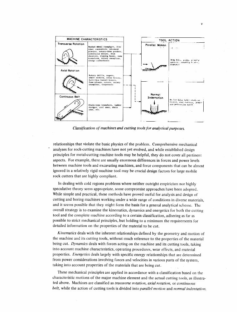
M A C H IN E C H A R A C T E R IS T IC S
T ra n s v e rs e R o ta t io nBufkf,t-wbeejl , disc saus^ excavators, pavement planers, rotary-drum graders, continuous miners, drum shearers, ripping booms, some tunnelera, rotary snowplows, dredge cutterheads
A x ia l R o ta tio n
Rotary drills, augers, shaft sinkers, raise borers, full-face tunnel borers, free miners, corers, rotary snowplows, trepanners
Co n tin u ou s B e lt
^2 Chain-type trenchers, ladder dredges, coal saws, shale saws, etc.
Classification o f machines and cutting tools for analytical purposes.
relationships that violate the basic physics of the problem. Comprehensive mechanical analyses for rock-cutting machines have not yet evolved, and while established design principles for metal-cutting machine tools may be helpful, they do not cover all pertinent aspects. For example, there are usually enormous differences in forces and power levels between machine tools and excavating machines, and force components that can be almost ignored in a relatively rigid machine tool may be crucial design factors for large mobile rock cutters that are highly compliant.
In dealing with cold regions problems where neither outright empiricism nor highly speculative theory seem appropriate, some compromise approaches have been adopted. While simple and practical, these methods have proved useful for analysis and design of cutting and boring machines working under a wide range of conditions in diverse materials, and it seems possible that they might form the basis for a general analytical scheme. The overall strategy is to examine the kinematics, dynamics and energetics for both the cutting tool and the complete machine according to a certain classification, adhering as far as possible to strict mechanical principles, but holding to a minimum the requirements for detailed information on the properties of the material to be cut.
Kinematics deals with the inherent relationships defined by the geometry and motion of the machine and its cutting tools, without much reference to the properties of the material being cut. Dynamics deals with forces acting on the machine and its cutting tools, taking into account machine characteristics, operating procedures, wear effects, and material properties. Energetics deals largely with specific energy relationships that are determined from power considerations involving forces and velocities in various parts of the system, taking into account properties of the materials that are being cut.
These mechanical principles are applied in accordance with a classification based on the characteristic motions of the major machine element and the actual cutting tools, as illustrated above. Machines are classified as transverse rotation, axial rotation, or continuous belt, while the action of cutting tools is divided info parallel motion and normal indentation.
VI
Transverse rotation devices turn about an axis that is perpendicular to the direction of advance, as in circular saws. The category includes such things as bucket-wheel trenchers and excavators, pavement planers, rotary-drum graders, large disc saws for rock and concrete, certain types of tunneling machines, drum shearers, continuous miners, ripping booms, some rotary snowplows, some dredge cutterheads, and various special-purpose saws, millers and routers. Axial rotation devices turn about an axis that is parallel to the direction of advance, as in drills. The category includes such things as rotary drills, augers and shaft-sinking machines, raise borers, full-face tunnel boring machines, corers, trepanners, some face miners, and certain types of snowplows. Continuous belt machines represent a special form of transverse rotation device, in which the rotor has been changed to a linear element, as in a chain saw. The category includes “digger chain” trenchers, ladder dredges, coal saws, shale saws, and similar devices.
In tool action, parallel motion denotes an active stroke that is more or less parallel to the surface that is being advanced by the tool, i.e. a planing action. Tools working this way include drag bits for rotary drills and rock-cutting machines; picks for mining and tunneling machines; teeth for ditching and dredging buckets; trencher blades; shearing blades for rotary drills, surface planers, snowplows, etc.; diamond edges for drills and wheels; and other “abrasive” cutters. Normal indentation denotes an active stroke that is more or less normal to the surface that is being advanced, i.e. one which gives a pitting or cratering effect such as might be produced by a stone chisel driven perpendicular to the surface. Tools working this way include roller rock bits for drills, tunneling machines, raise borers, reamers, etc.; disc cutters for tunneling machines; and percussive bits for drills and impact breakers.
A few machines and operations do not fit neatly into this classification. For example, certain roadheaders and ripping booms used in mining sump-in by axial rotation and produce largely by transverse rotation, and there may be some question about the classification of tunnel reamers and tapered rock bits. However, the classification is very satisfactory for general mechanical analysis.
Complete treatment of the mechanics of cutting and boring is a lengthy task, and in order to expedite publication a series of reports dealing with various aspects of the problem will be printed as they are completed. The main topics to be covered in this series are:
1. Kinematics of transverse rotation machines
2. Kinematics of axial rotation machines
3. Kinematics of continuous belt machines
4. Dynamics and energetics of parallel-motion tools
5. Dynamics and energetics of normal indentation tools
6. Dynamics and energetics of transverse rotation machines
7. Dynamics and energetics of axial rotation machines
8. Dynamics and energetics of continuous belt machines.
MECHANICS OF CUTTING AND BORING
PART 1: KINEMATICS OF TRANSVERSE ROTATION MACHINES
by
Malcolm Mellor
The performance of a rock-cutting machine depends heavily upon the forces that it can apply and withstand, and upon the power available for cutting. It also depends upon the geometry of the cutting elements and their motion relative to the rock, i.e. the kinematics of the machine. Kinematic conditions are very important, in that they affect machine performance both directly and indirectly, often setting the conditions that control the dynamics and energetics. Kinematic considerations are also important because they are completely general in their applicability, irrespective of the kind of material that is being worked. Finally, kinematic analyses are very easy to make, and often provide insights and ideas that are extremely valuable.
This report deals with transverse rotation machines, and some examples of this type of equipment are shown in Figure 1. The treatment is limited almost completely to actual cutting processes, and does not deal with transport and removal of cuttings unless there is an intrinsic relation to the cutting operation.
Terminology
Terminology in this field is far from uniform. Some terms used by the author are defined below.
Cutting modes. Three main cutting modes are distinguished, as illustrated in Figure 2.In upmilling (or up-cut milling) the cutting rotor is sunk into the work to a depth less than the diameter, the axis of rotation is parallel to the primary free surface, and the direction of rotation is such that the cutters move upward on the leading side of the rotor. In climb milling (or down-cut milling) the cutting rotor is sunk into the work to a depth less than the diameter, the axis of rotation is parallel to the primary free surface, and the direction of rotation is such that the cutters move downward on the leading side of the rotor. In the slot milling mode the rotor is cutting across its complete semi-circumference, and the axis of rotation is normal to the primary free surface. The primary free surface will usually be the surface of a semi-infinite medium, e.g. the ground surface or a tunnel face, but it can also be the upper surface of a finite slab, e.g. a concrete slab overlying soil, or a layer of ice floating on water.
Cutting depth d is the depth to which the cutting rotor is set into the work, measuring normal to the primary free surface (Fig. 3).

2 MECHANICS OF CUTTING AND BORING
a. Mobile disc saw used for cutting rock and concrete.
b. Road planer used for cold planing o f asphalt and concrete pavements.
Figure 1. Examples o f transverse rotation machines.

PART 1: KINEMATICS OF TRANSVERSE ROTATION MACHINES 3
c. Rotary snow plows used for clearing deep, dense snow.
Figure 1 (cont’d).

4 MECHANICS OF CUTTING AND BORING
d. Heading machine used in underground mining.
Figure 1 (cont’d). Examples o f transverse rotation machines.
PART 1: KINEMATICS OF TRANSVERSE ROTATION MACHINES 5
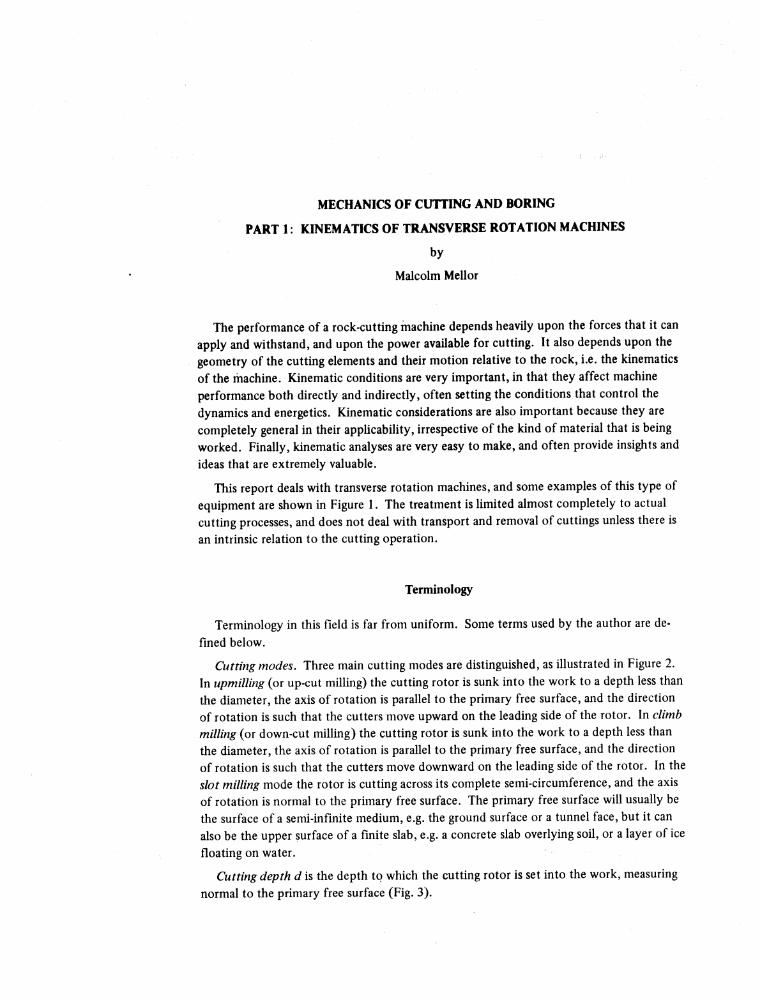
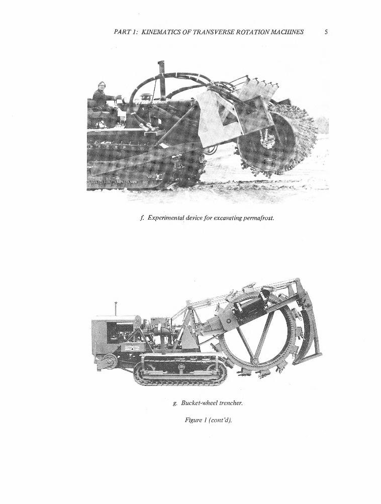
f Experimental device for excavating permafrost.
g. Bucket-wheel trencher.
Figure 1 (cont’d).

6 MECHANICS OF CUTTING AND BORING
a. Upmilling (up-cut milling) b. Climb Milling (down-cut milling)
c. Slot Milling
Figure 2. Cutting modes for transverse rotation devices.
Figure 3. Geometry o f an upmilling rotor.
Chipping depth % is the depth of penetration of the individual bit into the work, measuring in a radial direction (Fig. 4d). This is equivalent to what is sometimes called “uncut chip thickness” in machine tool work. For given machine speeds it varies continuously through the working sweep of the bit.
Effective tool length h is the maximum length of the individual bit that can safely penetrate the work, measuring in a radial direction. This might be the total radial extent of the bit, from holder to tip, or it might be the radial distance from the bit tip to the root of the tungsten carbide insert.
Rotor radius R is the radius of the drum, disc, or wheel measured to the effective tool tips (Fig. 3).
Tracking cutters are bits that sweep along a common path in a diametral plane. The number of tracking cutters in a complete revolution of the rotor is designated by n.

PARTI: KIN PM A TICS OF TRANSVPRSF ROTA TION MACHINPS 1
Figure 4. Geometry o f typical cutting tools.
Circumferential tooth spacing S is the circumferential distance between tracking cutters, measured at the tooth-tip radius, i.e. S = 2nR/n.
Lateral tooth spacing s is the distance between adjacent rings of tracking cutters, measuring along a generator of the rotor drum.
The rake angle of a tooth or bit j3j is the angle between the leading face of the bit (the rake face) and the radial through the tip, measured in a diametral plane in the sense shown in Figure 4. Note that the angle between a straight face and the radial through a point on the face actually varies from root to tip. t
The relief angle (or primary relief angle) of a bit 02 is the angle between the shoulder (or relief face) of the bit and the tangent through the cutting tip, measured in a diametral plane (Fig. 4). Note that the angle between a straight shoulder and the tangent through a given point on the shoulder actually varies from tip to heel.
The clearance angle (or secondary relief angle) at some point on the relief face behind the cutting tip is the angle between the relief face and the tangent through the point under consideration. Note that for constant clearance angle, the relief face has to be curved.
The included angle of a bit is the angle between the face and shoulder (rake face and relief face), measured in the diametral plane, i.e. @3 = 90° @2).
Angular position on the rotor is defined by the angle 6 between a radius running through the point of interest and a radius running normal to the traverse direction (Fig. 3).
Angular velocity of the rotor co (radians per unit time) will often be expressed as a frequency/in this discussion, i.e ./is the number of revolutions of the rotor per unit time (rev/min, rev/sec).

8 MECHANICS OF CUTTING AND BORING
Traverse motion is usually the linear motion of the entire cutting rotor relative to the material being cut, i.e. the linear motion of the'center of the rotor.
Traverse velocity U is the linear speed of the rotor center in a direction parallel to the primary free surface (Fig. 2).
A tooth trajectory is the path swept out by the tooth tip as the drum rotates and traverses. It is defined with respect to fixed space coordinates, i.e. it is motion relative to the uncut rock.
Tool speed u is given by the velocity of the bit tip relative to the rock. The tool velocity vector is given by the time derivative of the trajectory. The velocity component derived from drum rotation alone, uv is of special interest. ut is the tangential velocity of the bit tip relative to the center of the rotor (referred to as “surface feet per minute” in machine shop practice).
Chipping Depth
When a cutting rotor is upmilling at typical speeds (Fig. 3), each bit or blade enters the work at point ,4 with a chipping depth d that is virtually zero.* The chipping depth increases progressively through the working sweep, reaching a maximum value as the bit leaves the work at point C. If the rotor is climb milling, each bit enters the work at point C, taking maximum bite at the point of entry and tailing off to virtually zero bite at point of exit A . If the rotor is slot milling, each bit enters and leaves the work with virtually zero chipping depth, and takes its maximum bite as it sweeps through the center line of the slot.
Consider a bit or blade at position B in Figure 3. The drum is rotating at / revolutions per unit time, and if there are n cutters evenly spaced around the periphery at a given cross section of the drum, then the cutter at B will be replaced at B by the following cutter after a time interval of 1 ¡fn. The whole drum is moving forward at velocity U, and therefore in the time interval 1 Ifn it will move a linear distance of U/fn. The radial penetration of the cutter into uncut material, i.e. the theoretical radial chip thickness fi, is therefore
e = sin 0 . (1)fn
The maximum theoretical chip thickness for a given set of drum conditions, £max, is reached at point C, and is
£maxu_
fnsin 0max
= sin [cos“1 (1 — d/R)]
= U_fn
dR )A
(2)
* If the rotational speed is very low in relation to the traverse speed, the bit entering at point A will be faced with a hump of uncut material.

PART 1: KINEMATICS OF TRANSVERSE ROTATION MACHINES 9
where d is cutting depth (drum depth) and R is overall drum radius (measured to the cutter tips). If d > R , £m„ is achieved at 6 = ir/2.
The first coneem in applyingeq 2 is to ensure that for the machine! under consideration £mxx is in a sensible range. For example, it would not make much sense to operate a mining machine with a maximum chipping depth of the same order of magnitude as the tool tip radius, say 1 mm or less, nor would it make sense to operate with a theoretical chipping depth exceeding the gauge length of the cutting tools. In the first case the cutters would not operate properly, specific energy consumption and tool abrasion would be high, and the machine would produce little more than dust; in the second case the cutting head would be trying to destroy itself, plowing bit holders through uncut material and rubbing the face of the drum.
In practice, it is usually poeribie to set an upper limit for 8max by defining an effective tool length h (possibly the radial extent of carbide tips or hardfacing). If the bits are strong enough and the machine has enough power, then die upper limit for fimax is likely to be the optimum working value, mice specific energy consumption tends to decrease with increasing chip size, and abrasion wear is minimized by cutting large chips. If the maximum working extent of the cutting tool in the radial direction is h, the kinematic limit condition is
«max < *
i.e.
or
h > jr- sin [cos-1 (1 — d/R)]
(3)
Equation 2 and condition 3 are shown in dimensionless form in Figure 5, where £max is plotted against d/R with (U/fnh) as parameter. The kinematic limit for chipping depth is only reached when U/fnh > 1.0. If £max = h is taken as an optimum condition, then optimum operating conditions are given by the curve of Figure 6.
Some examples will show how these relationships can be used.
Example I. A 7-ft-diameter disc saw is cutting a 28-in.-deep slot in conglomerate in the upmilling mode. Traverse speed is 5 ft/min and wheel speed is 20 rev/min. There are essentially three rings of tracking cutters: a center ring and left and right gauge-cutting rings. Each ring has 50 evenly spaced bits. The problem is to check the chipping depth for each bit.
R = 3.5 ft, d = 2.33 ft, U = 5 ft/min, / = 20 rev/min, n = 50.
From eq 2
8max5.0
20 X 502.33 / 7.0 3.5 \ 2.33
0.00471 ft
0.0565 in.

10 MECHANICS OF CUTTING AND BORING
Figure 5. Dimensionless plot o f maximum chipping depth as a function o f drum depth for various ratios o f traverse speed to drum speed.
R
Figure 6. Dimensionless plot giving optimum ratio o f traverse speed to drum speed as a function o f drum depth (assuming £max = has an optimum condition).

PART 1: KINEMA TICS OF TRANSVERSE ROTA TIONMACHINES
This is probably too small for efficient working. The actual problem from which this example is adapted was more complicated, in that the teeth were set in clusters that repeated 10 times around the wheel circumference, with big spaces between clusters and small spaces between individual teeth in each cluster. The lead tooth of each cluster did an honest job, while the follower teeth just got polished or had a completely free ride (as evidenced by intact paint).
Example 2. A rotary drum grader/planer is removing asphalt to a depth of 4 in. by upniilling. The drum diameter is 3 ft, the drum speed is 50 rev/ min, and the cutting teeth are arranged in helical patterns that give staggered rings of tracking cutters with three cutters in each ring. Tooth design is such that 0.75 in. is the maximum safe chipping depth when allowance is made for chip clearance. Assuming that the machine is adequately stressed and powered, and has adequate traction, what is the maximum traverse speed that can be achieved before chipping depth becomes too big?
R = 18 in., d = 4 in., / = 50 rev/min, n = 3, h = 0.75 in.
Taking the equality of condition 3
U - 179 in./min = 14.9 ft/min.
With realistic values of drum width and drum power, specific energy estimates suggest that a machine operating in weak material could reach or exceed this traverse speed before the power limit is reached. Thus a kinematic limit of 14.9 ft/min is probably too low for balanced design.
The maximum chipping depth is limited kinematically by the effective tool length, but there is another factor to be considered in connection with the length of teeth or blades. As a cutter sweeps through the work it accumulates chips that have to be carried away somehow, and it is usually necessary for the chips cut by a tooth to be carried at least as far as the tool exit point (neglecting spillage). The rotor therefore has to have enough space between teeth, and between tooth tips and drum surface, to accommodate the chips accumulated in a working sweep.
Without worrying too much about the details of tooth spacing and indexing, consider unit width of the rotor, and calculate the cutting volume vc swept out by a single tooth or blade. This is given directly by integration of eq 1:
Chip Production and Carryover Volumes
e max emax
(4)o 0
12 MECHANICS OF CUTTING AND BORING
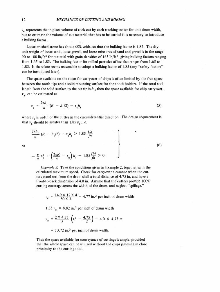
vc represents the in-place volume of rock cut by each tracking cutter for unit drum width, but to estimate the volume of cut material that has to be carried it is necessary to introduce a bulking factor.
Loose crushed stone has about 45% voids, so that the bulking factor is 1.82. The dry unit weight of loose sand, loose gravel, and loose mixtures of sand and gravel is in the range 90 to 100 lb/ft3 for material with grain densities of 165 lb/ft3, giving bulking factors ranging from 1.65 to 1.83. The bulking factor for milled particles of ice also ranges from 1.65 to 1.83. It therefore seems reasonable to adopt a bulking factor of 1.85 (any “safety factors” can be introduced later).
The space available on the rotor for carryover of chips is often limited by the free space between the tooth tips and a solid mounting surface for the tooth holders. If the total tool length from the solid surface to the bit tip is hv then the space available for chip carryover, va, can be estimated as
27ih.
V 2 > - S A < 5 >
where sc is width of the cutter in the circumferential direction. The design requirement is that va should be greater than 1.85 vc, i.e.
or
2 i R - V 2) - > 1-85 f
£ h2- + ( 2nR - , w - 1.85 o.n « \ n <7 *
(6)
Example 3. Take the conditions given in Example 2, together with the calculated maximum speed. Check for carryover clearance when the cutters stand out from the drum shell a total distance of 4.75 in. and have a front-to-back dimension of 4.0 in. Assume that the cutters provide 100% cutting coverage across the width of the drum, and neglect “spillage.”
vc = 3 * ^ = 4.77 in.3 per inch of drum width
1.85 vc = 8.82 in.3 per inch of drum width
va = ( l8 - - 4.0 X 4.75 =
= 13.72 in.3 per inch of drum width.
Thus the space available for conveyance of cuttings is ample, provided that the whole space can be utilized without the chips jamming in close proximity to the cutting tool.

PART 1: KINEMATICS OF TRANSVERSE ROTATION MACHINES 13
Figure 7. Dimensionless plot o f maximum excavation rate as a function o f drum depth.
Maximum Excavation Rate as a Function of Cutting Depth
The excavation rate per unit drum width, v, is
v = Ud. (7)
However, the maximum excavation rate is not necessarily proportional to cutting depth, even if the machine has enough power to drive the rotor adequately at the highest available traverse speed. The reason for this is that maximum chipping depth £max increases with increasing cutting depth d 9 and Cmax is limited by effective tool length h. Substituting for U\n eq 7 from eq 3:
vmaxhfn
(2R/d — \ ) Vl'(8)
For purposes of illustration in Figure 7, maximum excavation rate at any given cutting depth has been given as a fraction of the maximum excavation rate at d = R. The equation for this normalized maximum excavation is
^ m a x )= (2R /d - 1)- n - f c
d=R(9)
Tooth Trajectories
For calculation of chipping depth it is convenient to think of each bit as swinging through a circular arc about the center of the rotor, but for other purposes it may be necessary to consider the path of the bit tip relative to the rock. In the latter case the traverse motion of the rotor has to be added to the rotational motion.
Consider the motion of a single tooth after it enters the work at point A in Figure 3, and take point A on the rock as the origin of coordinates. The traverse direction is the x- direction and the jy-direction is normal to the traverse direction. After the rotor has turned
14 MECHANICS OF CUTTING AND BORING
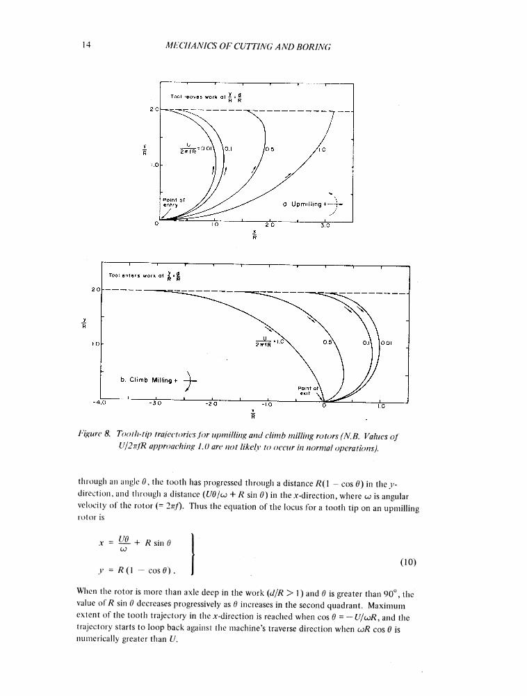
Figure 8. Tooili-tip trajectories for upmilling and climb milling rotors (N.B. Values o f U/2ttJR approaching 1.0 are not likely to occur in normal operations).
through an angle 0 , the tooth has progressed through a distance /?(1 - cos 6») in the v- dircetion, and through a distance (Ud/ot + R sin 0) in the x-direction, where co is angular velocity oi the rotor (= 2vf). Thus the equation of the locus for a tooth tip on an upmilling rotor is
x = ML + r sin g00
y - R (1 — cos 6 ).(10)
When the rotor is more than axle deep in the work (d/R > 1) and 6 is greater than 90°, the value of R sin 0 decreases progressively as 0 increases in the second quadrant. Maximum extent of the tooth trajectory in the x-direction is reached when cos 6 = - U/coR, and the trajectory starts to loop back against the machine’s traverse direction when toR cos 0 is numerically greater than U.

PART 1: KINEMATICS OF TRANSVERSE ROTATION MACHINES 15
If the rotor is climb milling, i.e. rotating in the opposite sense to the wheel shown in Figure 3, it is convenient to take the point of tooth exit as the origin (po in ts in Fig. 3), while retaining the original definition of angular position. The equation of the tooth tip locus for climb milling then becomes:
x = - Ü1 + r sin eCO
y = R (1 — cos d).(11)
Figure 8 shows tooth trajectories for various values of traverse speed relative to rotational speed, for both upmilling and climb milling. The x andy values are normalized with respect to R, i.e. x and y are given as fractions or multiples of the rotor radius. The parameter of the curves isU/coR, or U/2-nfR. When the value of Ul2nfis high, the tooth tends to make a long forward sweep relative to the rock, but when U/2irfis small, the tooth comes close to sweeping through a circular arc. Typical values of U/2irfR for existing rockcutting machines are in the range 0.005 to 0.05, and for this range the tooth sweep is almost circular.
If 0max ^ 27x/n, a complete trajectory can be traced out by a single tooth before the next tooth enters the working sweep, but if 0max > 27t/yi the trace left by one tooth is being attacked by the following tooth before the first has finished its working sweep. It is easy to see that serious vibrations would be set up with 0max < 27r/« if some damping arrangements were not made. A simple way of smoothing out these potential vibrations is to stagger laterally adjacent rings of cutters, for example by setting cutters along helical paths.
Tool Speed
The speed of each bit relative to the rock is determined by the combination of rotational motion and traverse motion, and is best specified by two orthogonal components, resolving parallel and normal to the traverse direction. Following the notation of the previous section, tool velocity components for upmilling,x and y , are:
x = U + Reo cos 6 = U + 2nRf cos 6
y = Reo sin 6 = 2nRfsind.( 12)
Still maintaining the notation of the previous section, the tool velocity components for climb milling are:
* = U — Rco cos 6 = U — 2nRf cos 6(
y = — Rco sin 8 = — 2nR f sin Q.
In most practical situations, 27r/?/is much greater than U, and the resultant tool velocity u is given to a sufficient degree of accuracy by the tangential velocity arising from rotation alone, wt , i.e. u ^ ut =Roo = 2nRf. In machine shop practice, ut is generally referred to as “surface feet per minute,” or “SFM.”

16 MECHANICS OF CUTTING AND BORING
Figure 9. Maximum rotor speed plotted against rotor diameter fo r various existing rock-cutting machines that operate with transverse rotation. Lines indicating m axi
mum tool speed are drawn on the plot.
Most transverse rotation rock cutters have tool speeds in the range 100 to 1000 ft/min, or about 0.5 to 5.0 m/sec, as is shown in Figure 9. Low tool speeds tend to be associated with deep “bite” (large fi) and high tool forces, but they tend to minimize wear rate by keeping tip temperature relatively low. Very high tool speeds usually imply a surface scraping action, with the tool tip in effect grinding itself away. In underground mining, high tool speeds increase the chances of sparking and gas ignition. Valantin et al. (1964) found that the rate of increase of wear speed with tool speed went up abruptly when a certain tool speed was reached in a particular rock type; the critical tool speed was about 100 ft/min (0.5 m/sec) in hard rock, about 300 ft/min (1.6 m/sec) in medium strength rock, and about 700 ft/min (3.5 m/sec) in soft rock. However, the critical tool speed is likely to be dependent on additional factors, such as the length of the working stroke for each tool.
Very high tool speeds sometimes occur on experimental machines, possibly because of limitations on torque or design skill, but they are rare on production machines. Some exceptions can be seen in Figure 9, which shows that one manufacturer offers “rock cutters” with tool speeds up to 4600 ft/min.

PART 1: KINEMATICS OF TRANSVERSE ROTATION MACHINES 17
Figure 10. Maximum rotor speed plotted against rotor diameter for various transverse rotation devices.
Figure 10 shows typical ranges of tool speed for various transverse-rotation machines other than rock cutters. These include metal-cutting machine tools, general purpose wheel grinders, woodworking machines, friction saws, and rotary snowplows.
Tooth Relief Angles — Kinematic Considerations
When a cutting tooth is working the rock surface traced out by the previous tooth, it follows a path that is not perfectly parallel with that surface. This effect can be seen by taking two identical tooth trajectories (Fig. 8) and setting them apart in the x-direction by
18 MECHANICS OF CUTTING AND BORING
a distance equivalent to the forward travel of the rotor in the time taken for successive passes of tracking teeth through a given angular position.* If the shoulder, or relief face, of the cutting tool is exactly tangential to the rotor, it will grind agaipst uncut material and impede penetration of the cutting edge. For this, and other, reasons the shoulder behind the cutting edge is usually cut back to give a relief angle, or clearance angle, that keeps it clear of uncut material. The calculations made in this section give the absolute minimum values of relief angle that are set by the geometry of the cutting situation; additional considerations will be introduced in a later section after a discussion of the factors that control tooth forces.
The minimum relief angle (“kinematic” relief angle) that is needed to avoid scraping of the shoulder, , is given by the difference between the slope of the tooth trajectory and the slope of the tangent to the rotor for the same angular position. The slope of the tooth trajectory, dy/dx, is obtained by differentiating eq 10 or eq 11:
for upmilling
for climb milling
dy _ sin 9 dx U/Ru) -f cos 9
dy _ sin 9_____dx ~U/Rco + cos 9
(14)
Since the slope of the tangent at angular position 9 is tan 9 , the minimum required relief angle at that position is
for upmilling
for climb milling
02 0 tan 1 ( U/RS™+cos d )
P2 = e - tan 1 ( -U / r Z + cos 0 ) •
(15)
If the maximum cutting depth d can be firmly specified, then the required value of 02 can be obtained from eq 15 by substituting the maximum value of 0, which is given by 0 = cos“1 (1 —d/R ). However, if the rotor is intended to slot mill or to cut to some unspecified maximum depth, then a maximum value of 02 can be found by differentiating eq 15 and setting 302/30 = 0. In this way it is found that the required maximum value occurs at 9 = cos“1 (—U/Rw) for upmilling, and at 9 = cos“1 (U/Rco) for climb milling, i.e. 02 is a maximum where the slope of the trajectory is 90°. The solutions for upmilling and climb milling are, of course, essentially identical when a complete 180° working sweep is considered (the direction of rotation is largely irrelevant in slot milling). For upmilling, however, the maximum value of j3'2 is not reached until 9 > 90°, while for climb milling the maximum value is reached with 9 < 90°.
As was mentioned earlier, U/Rco, or U/friRf, is between 0.005 and 0.05 for typical operation of existing machines, so that the required value of 02 for unlimited depth cutting would probably be in the range 0.25° to 3°, and the critical value of 9 would be close to 90°. For most practical purposes it is therefore acceptable to calculate 02 for unlimited depth cutting as
* This exercise illustrates the approximation involved in eq 1, as it shows that Q is finite at 6 = 0 and 0 = 180°.

PART 1: KINEMATICS OF TRANSVERSE ROTATION MACHINES 19
P'2 = cos-1 (—U/Rco) — 7t/2 = cos“1 (—U/lirfR) — 90° =
= cos“1 (—U/ut) — 90°. (16)
Example 4 (Part 1). A rotary drum machine is required to cut by up- milling to a maximum depth of 10 in. with a maximum traverse speed of 20 ft/min. Overall drum diameter is 40 in., and minimum drum speed is 50 rev/min. What is the required minimum value of relief angle (i.e.“kinematic” relief angle) at the tip of the cutter?
ffmax = C05rl 0 " 10/20) = 60°
(U/27ifR)max = 0.0382
P2 - 60 - tan 1 ( 0 0 3 8 2 + o.50 ) 1-9 '
In the above example, and almost any other plausible example, the required minimum relief angle for the bit tip turns out to be much smaller than the relief angles that are commonly designed into rock cutting tools on the basis of evolution and practical experience. Whereas the calculated values of 02 are usually less than 3°, actual values of 02 for commercial bits set on working drums tend to be in the range 7° to 15°. There are both kinematic and dynamic reasons for this difference, but before going on to them it may be well to mention some “practical,” but probably unnecessary, reasons that are sometimes given.
In discussions with users and makers of rock cutting tools, a number of speculative explanations for high relief angle have been offered. First of all, there is obviously a need for a margin over the absolute minimum theoretical value. Secondly, the tool has to provide clearance against an irregular surface, not a perfectly smooth one, which is a valid point for a machine with high radial compliance (but not for a perfectly rigid machine). Thirdly, cuttings may recycle around the bit, and some allowance may have to be made for this. Finally, there may be a feeling that higher relief angle makes some provision for wear of the bit tip. All these arguments have a certain validity, but there are two further factors, one geometric and one dynamic, that can be assessed quantitatively and that are capable of producing complete compatibility with empirical designs.
Figure 4c shows schematically a cutter with straight rake and relief faces. The primary relief angle at the tip of the cutter, 02, defined with reference to the tangent through the tip, is actually greater than the secondary relief angle, or clearance angle, at the rear corner of the relief face, 02, again defined with reference to the tangent through that corner:
P'2 = P'2 ~ M 07)
where AO & s jR . This means that the relief face has to be curved (as in a “panot-beak” pick), or else the clearance angle at the rear corner of a straight shoulder bit has to be at least the required minimum value 02. Example 4 can now be completed.

20 MECHANICS OF CUTTING AND BORING
Example 4 (Part 2), Following directly on from Part 1 of this example, what is the required minimum relief angle, relative to the cutter tip, if the cutters have flat relief faces with a front-to-back dimension (sc) of 3.5 in.?
Ad « ^ 0.175 radians ^ 10°.
Required overall relief angle (relative to tangent at cutter tip)
= 02 + Ad = 11.9°.
The actual machine used as a basis for this example had its picks set to give a 7.5° relief angle relative to the tangent through the center of the flat relief face, i.e. the primary angle at the pick tip was 12.5°, the clearance angle at the rear shoulder was 2.5°, or was 2.5°.
Perhaps the most important thing that emerges from a careful geometric analysis of relief angle is the discovery that the problem is a little more complicated than it might appear at first sight. Special care is needed when bits have long relief faces, e.g. when heavy “bullet bits” are being fitted to a machine. Care is also needed in setting reversible picks that have two sets of carbide edges, since any scraping at the rear end of the relief face could result in the inactive carbide being plucked out of its seat.
This completes the kinematic consideration of relief angle but, as was mentioned above, there is still a dynamic factor to be considered. The dynamic implications and wear problems will be discussed in detail in another section, but for the present it will suffice to state that even when a cutting tool is planing along a flat surface, where the required “kinematic” relief angle is close to zero, it is found that cutting forces rise sharply when the relief angle drops below about 5°. Thus the primary relief angle should probably have a minimum value of approximately (fi2 + 5°), and with a straight relief face there will need to be additional allowance for clearance of the rear corner.
Tool Rake Angles
By the convention adopted for this discussion (see Terminology), nominal rake angle at the tip of a tool is the angle between the leading face of the tool and a radial from the center of the rotor running through the tip of the tool. However, with reference to the working face the effective rake angle is the angle between the leading face of the tool and the normal to the tool tip trajectory. The difference between the nominal rake angle and the effective rake angle at any given angular position on the drum is thus equal to the minimum kinematic relief angle for that position, j3'2. The effective rake angle (i j )eff is
( ^ l ) e f f 0 i + 0 2 * ( 1 8 )
Since p2 is not likely to exceed 3° on typical transverse-rotation machines, this effect is not of much practical significance. However, it can be important on axial-rotation devices.
In the listing of terminology it was pointed out that nominal rake angle changes with position on a straight rake face according to the definition adopted, just as nominal relief angle changes along a straight relief face. This is not likely to be of practical significance.
PART 1: KINEMATICS OF TRANSVERSE ROTATION MACHINES 21
■'/Awrs w
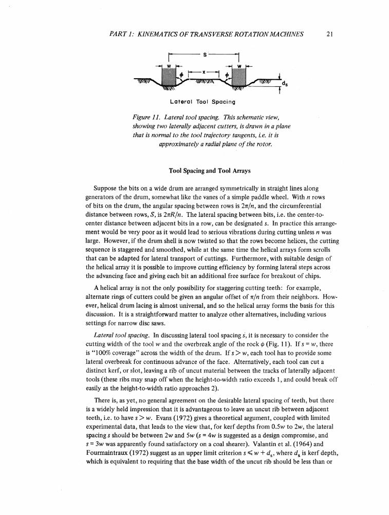
Lateral Tool Spacing
Figure 11. Lateral tool spacing. This schematic view, showing two laterally adjacent cutters, w drawn in a plane that is normal to the tool trajectory tangents, i.e. it is
approximately a radial plane o f the rotor.
Tool Spacing and Tool Arrays
Suppose the bits on a wide drum are arranged symmetrically in straight lines along generators of the drum, somewhat like the vanes of a simple paddle wheel. With n rows of bits on the drum, the angular spacing between rows is 27r/n, and the circumferential distance between rows, S, is InR/n. The lateral spacing between bits, i.e. the center-to- center distance between adjacent bits in a row, can be designated s. In practice this arrangement would be very poor as it would lead to serious vibrations during cutting unless n was large. However, if the drum shell is now twisted so that the rows become helices, the cutting sequence is staggered and smoothed, while at the same time the helical arrays form scrolls that can be adapted for lateral transport of cuttings. Furthermore, with suitable design of the helical array it is possible to improve cutting efficiency by forming lateral steps across the advancing face and giving each bit an additional free surface for breakout of chips.
A helical array is not the only possibility for staggering cutting teeth: for example, alternate rings of cutters could be given an angular offset of 7x/n from their neighbors. However, helical drum lacing is almost universal, and so the helical array forms the basis for this discussion. It is a straightforward matter to analyze other alternatives, including various settings for narrow disc saws.
Lateral tool spacing. In discussing lateral tool spacing s, it is necessary to consider the cutting width of the tool w and the overbreak angle of the rock 0 (Fig. 11). If s = w, there is “ 100% coverage” across the width of the drum. If s > w, each tool has to provide some lateral overbreak for continuous advance of the face. Alternatively, each tool can cut a distinct kerf, or slot, leaving a rib of uncut material between the tracks of laterally adjacent tools (these ribs may snap off when the height-to-width ratio exceeds 1, and could break off easily as the height-to-width ratio approaches 2).
There is, as yet, no general agreement on the desirable lateral spacing of teeth, but there is a widely held impression that it is advantageous to leave an uncut rib between adjacent teeth, i.e. to have s > w. Evans (1972) gives a theoretical argument, coupled with limited experimental data, that leads to the view that, for kerf depths from 0.5w to 2w, the lateral spacing s should be between 2w and 5w (s = 4w is suggested as a design compromise, and s = 3w was apparently found satisfactory on a coal shearer). Valantin et al. (1964) and Fourmaintraux (1972) suggest as an upper limit criterion s < w + ds, where ds is kerf depth, which is equivalent to requiring that the base width of the uncut rib should be less than or

22 MECHANICS OF CUTTING AND BORING
equal to its height. Roxborough (1973) and Roxborough and Rispin (1973a, 1973b) find that specific energy is minimized with s = w + kds, where k has values from 1.5 to 3 for various materials. This is already a conflict of views, and the situation is further confused by Barker’s (1964) experimental finding that the specific energy consumption for drag bit cutting of rock reaches a minimum when s = w, i.e. 100% coverage gives the most efficient working.
Referring to Figure 11, it appears that the lateral spacing criterion can be expressed quite logically in terms of the chipping depth ds and the overbreak angle 0 as
s = w + 2cds tan 0 (19)
where c is a constant that describes the desired degree of overlap in the adjacent overbreaks (with c - 1 the uncut width x in Fig. 11 would be zero; with c = 0.5 there would be 50% overlap of the side breaks). Roxborough (1973) gives data for four types of rock in which 0 varies from 52° to 70° and (2c tan 0) for minimum specific energy varies from 1.5 to 3; these results imply values of c ranging from 0.41 to 0.66. However, while eq 19 may appear logical, it is not necessarily useful as a practical criterion, since chipping depth ds varies from zero to some maximum value in a transverse-rotation machine.
Simple investigations of lateral tooth spacing may be a little unrealistic, in that they consider a plane surface with idealized parallel kerfing cuts of equal depth. Most real machines have their teeth staggered in helical arrays, and the advancing face tends to have a stepped profile when viewed in a radial plane. Even if laterally adjacent teeth did sweep through the work together, and optimum kerf-and-rib geometry were produced in a single tooth pass at 6 max, many tooth passes would be required to produce the same optimum geometry at small values of 0. Furthermore, many types of cutting teeth taper towards the tip, so that the full width of the tool is not utilized until a certain chipping depth has been reached. Finally, an uncut rib may tend to “wash out” the carbides by abrasion of the supporting steel.
In view of these uncertainties the machine designer is forced to make a choice, drawing on personal experience and knowledge of relevant rock properties. So far, in designing transverse-rotation machines the writer has tended to rely on Barker’s (1964) results, taking 1 < s/w < 2 as a general range, with close spacing in tough materials and wider spacing in more friable materials. This practice is not in much conflict with the findings of Valantin et al. (1964), Roxborough (1973) and Roxborough and Rispin (1973), since in most cases 0 < ds < w.
Helical tooth arrays. As was mentioned earlier, helical drum lacing is convenient for a number of reasons, one of which is a potential for improved cutting efficiency. Consider three adjacent rings of cutters, A, B and C, which are twisted relative to each other in such a way that each transverse row of cutters lies along a helix. Number 1 of ring A sweeps through angular position 0 and creates a new surface. While the Number 1 cutter on ring B is swinging up to position 0 the drum is moving forward, so that the new surface cut by bit Number 1 on ring B is in advance of the surface cut by bit Number 1 on ring A. Similarly the surface cut by bit Number 1 on ring C is further advanced than the surface cut by bit Number 1 on ring B, and so on. When the Number 2 cutter on ring A reaches position 0 it is attacking a “step,” i.e. there is a free surface on the side adjacent to ring B

PART 1: KINEMATICS OF TRANSVERSE ROTATION MACHINES 23
(see Fig. 13 for a graphical example). The design problem is to optimize this step-cutting sequence for easy breakout.
The time interval t x between successive passes of tracking cutters through a given angular position is
t x = 1 Ifn (20)
and the time interval t2 between passage of one cutter and its diagonally adjacent neighbor (e.g. the time between passage through 6 of No. 1 on ring A and No. 1 on ring B) is
stance ' 2 “ 2tiR f
(21)
where ax is the helix lag angle, measured from a generator of the drum surface.
The height of the step thus formed, z (measured in a radial direction), is
Us tan a, Usd tan a , xViz = ..A sin d = ------------ •
2nR2f ' d >2itRf(22)
For easy breakout of chips, it is probably desirable to have the step height z as large as possible, recognizing that it cannot be any greater than the chipping depth £. In other words, t2 has to be smaller than t x, but as close to t x as is practically reasonable. Another way of expressing this is to talk in terms of phase lag between diagonally adjacent teeth: the phase lag should be almost, but not quite, equal to 2ii/n.
However, it is fairly obvious that a phase lag very close to 27j/n is impractical, since the lateral rows of teeth line up very close to the generator direction, giving a potential for severe cutting vibrations. Another factor is that the teeth are concentrated in tightly packed lines instead of being well dispersed over the drum surface, leading to stressing problems with the drum shell and to overcrowding of the pick boxes.
Another consideration in setting a limit to the phase lag is that each step should probably be formed at least one full chip length ahead of the tooth that is to break out that step.If chip length is taken as 2£ (see, for example, Wagner 1971), the limit is
tan dj < j (nR/n - £max). (23)
If £max is fairly large compared to irR/n, say 20% of nR/n, condition 23 may be sufficient to give a workable layout, but if £max is relatively small, say less than 5% of nR/n, condition 23 will not give adequate dispersal of teeth. Of course, it is also necessary to take account of lateral tooth spacing s in making this judgment.
To avoid the complications of abstract geometry, and to illustrate how practical considerations can override simple kinematic considerations, it may be helpful to work some examples.
Example 5. A device for breaking permafrost soils has a rotating drum 12 ft wide with a diameter of 5 ft across the pick tips. Drum rotation direction has to be capable of reversal by reversing the picks in their boxes,

MECHANICS OF CUTTING AND BORING
and there has to be no significant change in the drum lacing geometry when rotation is reversed. Lateral transfer of cuttings is not called for in the basic version, but there has to be no net lateral force on the drum. The problem is to design a layout for setting of pick boxes on the drum shell.
From other considerations (tool speed, tool wear) it has been decided that n = 3, and maximum chipping depth £max has been set at 1 in. for normal operation, with provision for £max = 2 in. when operating in weak material. Lateral tooth spacing s is to be 2 in., and overall length of tooth and holder is 4.5 in.
Strictly speaking, layout calculations should be made for the cylindrical surface defined by the pick tips, but as the actual design drawings have to show the positions of pick holders on the drum shell it is easier to work directly with the drum surface, which in this case has a radius R d = 25.5 in. The absolute limit of ax on the drum shell, given by t2 = t x, is 87.85°. The corresponding value of a 2, the angle between the generator and the other line drawn through laterally adjacent picks, is 0°. If maximum chip length 2ftmax is taken as 4 in., the corresponding dimension at the drum shell surface is 3.4 in.; the limit value of a x from condition 23 is 87.72°, and the corresponding value of a2 is 59.11°. These two sets of values serve to illustrate that a x is too insensitive to use for practical layout purposes; it is much better to work with a2.
With a2 = 59° the dispersal of bits is not very satisfactory, as can be seen by plotting the layout. However, by making a series of graphical adjustments the bits can be arranged approximately equidistant from their nearest neighbors without sacrificing too much of the desired phase lag. Figure 12 shows a reasonable layout with ax = 87.4° and a2 = 78.1° ; the step height is 82% of the maximum possible value. It might be noted that scrolls for lateral transport of cuttings do not have to conform to the cutting helices - they can be laid along other lines of bits, as indicated in Figure 12. If the machine happens to work in weak, friable material where wider lateral spacing of bits would be advantageous, alternate rings of bits can be removed without destroying symmetry, although step height will then drop to 66% of the maximum possible value. Figure 12 shows the layout for half of the drum width; by making the other half a mirror image, i.e. by arranging the developed helices as chevrons, lateral drum forces can be balanced out. However, if lateral transfer scrolls were required, rotation in one direction would feed cuttings to the drum ends, whereas reverse rotation would feed cuttings to the drum centerline.
The lateral relief obtained with the helical cutter array is illustrated in Figure 13, which gives the schematic chipping sequence for the drum lacing of Figure 12 when operation is such that £ = w/2.
Example 6 (Part 1). A large disc saw working in rock, concrete and frozen ground requires more durable cutters, and a suitable layout has to be determined. From considerations of tool forces and wear, a new cutter has been selected, and it is found that a maximum of 60 cutters can be attached conveniently to the rim of the wheel. Wheel radius R will be 43 in. to the cutter tips, and the required working width (sawcut width)

PART 1: KINEMATICS OF TRANSVERSE ROTATION MACHINES 25
Figure 12. Drum lacing arrangement as developed in Example 5.

26 MECHANICS O f CUTTING AND BORING
fV1T Î T ] - J T-L« ** ■ *» » ,,
‘ — L— LReference Surface „ Lateral
Repetition
Ij
Directionof Advance -t = w/2
Figure 13. Chipping sequence for the helical tooth array illustrated in Figure 12. In this schematic, the effect is made pronounced by taking
8 - w/2.Chipping Sequence
f =35 rpm U= I20in/min n= 10 d=30 in R =43in
Left Right
Middle Inner Outer
Segment Width
---------------- 3.7"---------------- HInitial Gauge
h-------- 3-5"---------HNominal Gauge
0 I 2 3 in.1 _____ I_____ I_____ Ia. Gauge block setting angles and
tracks of pick tips
xlI
I I
Î2 !
x3
x5
x4
I
b. Tooth lacing
x 6
4 in.
Figure 14. Cutter arrangement appropriate to the conditions given in Fxample 6, with schematic illustration o f the resulting chipping
sequence.

PART 1: KINEMATICS OF TRANSVERSE ROTATION MACHINES 27
is 3.5 in. To simplify maintenance and stockage of spares, cutters will be attached to 10 identical removable perimeter sections, so that there will be at least 10 repetitions for each tool setting. The problem is to find a suitable cutter arrangement and to determine the chipping sequence that will result.
There are only two obvious symmetrical arrangements: one which assigns a different position to each of the six cutters on a sector plate, and one which uses three different cutter positions with a repetition on each plate. The former is chosen so as to obtain reasonable coverage at the chipping depths to be expected in hard material, and the arrangement shown in Figure 14 is eventually arrived at. This sets the cutters somewhat outside the required width so as to allow for wear. Having chosen a cutter pattern, it is a simple matter to calculate and plot the chipping sequence for any given set of operating conditions, as illustrated in Figure 14.
Example 6 (Part 2). The wheel is intended to work mainly in two distinct types of material. From prior experience and power considerations it is expected that the wheel will be run at 44 rev/min in both materials; in the weaker material traverse speed is expected to be 200 in./ min at a cutting depth of 33 in., while in stronger material traverse speed is expected to be 60 in./min at a cutting depth of 31 in. What will the maximum chipping depth be in each of these cases?
With7? = 43 in .,/= 44 rev/min, n - 10, and d and U as given above, maximum chipping depth £max is obtained directly from eq 2 as 0.44 in. for the weaker material and 0.13 in. for the stronger material.
Literature Cited
Barker, J.S. (1964) A laboratory investigation of rock cutting using large picks. International Journal of Rock Mechanics and Mining Sciences, vol. 1, no. 4, p. 519-534.
Evans, I. (1972) Line spacing of picks for effective cutting. International Journal o f Rock Mechanics and Mining Sciences, vol. 9, p. 355-361.
Fourmaintraux, D. (1972) Machines foreuses pour tunnels et galeries. Laboratoire des Ponts et Chausse'es, Paris, Rapport de recherche no. 20.
Roxborough, F.F. (1973) Cutting rock with picks. The Mining Engineer, June, p. 445-455.Roxborough, F.F. and A. Rispin (1973) The mechanical cutting characteristics of the Lower Chalk.
Tunnels and Tunnelling, January/February, 15 p.Roxborough, F.F. and A. Rispin (1973) A laboratory investigation into the application of picks for
mechanized tunnel boring in the Lower Chalk. The Mining Engineer, October, p. 1-13.Valantin, A., P. Belugou and P. Guillon (1964) Etude des pics des machines d’abattage. Rev. de
l ’Industrie Minérale, October, p. 815-848.Wagner, H. (1971) Der Mechanismus der Spanentstehung beim Zerspanen von Gesteinen. Rock
Mechanics, vol. 3, no. 3, p. 159-174.