mechanics kit #mechkt...3 verifying archimedes’ princple archimedes’ principle is a vital...
TRANSCRIPT

1
Phone: 417.347.7431Fax: [email protected] North Deffer DriveNixa, Missouri 65714
Introduction
Mechanics refers broadly to the study of forces at work on an object and the motions caused by those forces. It looks at objects at rest, in motion, and with the potential to be moved. Three essential concepts in mechanics include force, mass, and motion. Classical mechanics looks at the motions and movements of bodies, almost always larger than an atom, moving at speeds much slower than the speed of light. Think of classical mechanics as the study of ideas relating to and stemming from Newton’s Laws of Motion. Einstein improved upon classical mechanics with his theories of general
and special relativity by helping to integrate the movements of objects at speeds at or approaching the speed of light. Quantum mechanics, on the other hand, deals with observing and predicting the movements of atomic or subatomic masses. Though these theories all help describe the interactions between masses of various sizes, we have yet to be successful in integrating these two theories into the hypothetical goal of physics – the “theory of everything.”
This kit will help you to build a strong foundational understanding of classical Newtonian mechanics.
Experiments
1. Verifying Archimedes’ Principle
2. Observing and Experimenting with Torque
3. Verifying Hooke’s Law
4. Resolving Forces
Mechanics Kit#MECHKT
Warning:• Not a toy; use only
in a laboratory or
educational setting.
• May contain lead.
• California Proposition
65 Warning: This
product may contain chemicals known to
the State of California to cause cancer and
birth defects or other reproductive harm.
5. Verifying the Law of Parallelograms
6. Frictional Force on a Horizontal Plane
7. Frictional Force on an Inclined Plane
8. Friction and Acceleration of a Cart

2
Components
1. Dynamometer (5N)
2. Dynamometer (2.5N)
3. Stopwatch
4. Weight Box
5. Graduated Cylinder (100ml)
6. Double-Scale with Clip
7. Wooden Friction Block with Hook
8. Solid Aluminum Cylinder
9. Beaker (250ml)
10. Meter Tape (3m and 13mm)
11. Pans with Hooks (x2)
12. Single-Scale with Clip
13. Beam Balance with Pointer
14. Circular Protractor
15. Springs (2.5N and 1N)
16. S-Shaped Hooks (x2)
17. Weight Hangers (x2) and Slotted Weights (20g, x6)
18. Rod with Holes and Screw (40cm)
19. Rod with Center Screw (35cm)
20. Rod (35cm)
21. Rods (50cm, x2)
22. Inclined Plane, Protractor, Plumbob
23. Thread
24. Boss Head Clamps (x4)
25. Plastic Trolley with Hook
26. Base Supports (x2)
1 2 6
913
3
8
11
7
15
10
14
5
12
4
16 17
18192021
22 2324 25 26
Parts List

3
Verifying Archimedes’ Princple
Archimedes’ Principle is a vital concept in fluid mechanics. It states that any object submerged in a fluid (a gas or a liquid) is acted upon by an upwards force, known as buoyancy, that is equal to the mass of the amount of the fluid displaced by the object. If the buoyant force is greater than the mass of the object in the fluid, it will float. For this floating object, the mass of the displaced volume of fluid is equal to the mass of the object. If the buoyant force is less than the mass of the object in the fluid, the object will sink beneath the surface of the fluid. The submerged object will now have an apparent mass that is less than its actual mass by an amount equal to the mass of the fluid displaced by the object. Follow the instructions below to explore this concept.
1. Assemble your kit so that it matches the image below. Using the parts list on page 2 for reference, this experiment requires the following parts: #26, #18, #21, #20, #6, #13, #24, #8, #11, #4, #5, and #9. The pointer needle should be centered in the scale. If it is not centered, tweak your assembly until it is and the beam balance can move freely.
2. To get to the starting point of the experiment, hook the aluminum cylinder to the bottom of one of the pans, counterbalance it by placing weights on the other pan, fill your beaker with water, and place the beaker beneath the aluminum cylinder.
3. Raise your beaker up with your hands until it
touches the base of the cylinder. Observe the needle move as the buoyant force of the water causes the cylinder to have a lower apparent mass.
4. Rebalance the pans by removing weights from the pan opposite the cylinder. This removed mass is equal to the mass of the water that the cylinder is displacing. This amount is equal to the buoyant force.
5. Use the formulas below to mathematically confirm these observations.
• F = Force (Newtons)
• p = Density (kg/m3)
• M = Mass (kg)
• V = (m3)
• pf = Density of the Fluid
• pg = Density of the Object
• g = Gravity (9.8m/s2 on Earth)

4
Observing and Experimenting with Torque
When force is applied to an object that isn’t fixed to anything, that force generally moves the object in the direction of the force. However, when an object is fixed to a single point, referred to as a pivot, the force will only cause the object to rotate around the pivot. This rotational force is known as torque or moment.
1. Assemble your kit so that it matches the image below. Using the parts list on page 2 for reference, this experiment requires the following parts: #26, #18, #21, #20, #6, #13, #24, #16, and #17. Begin the experiment with the weight hangers hung on the holes in the balance closest to the pivot and equipped with no additional weights.
2. Add one weight to each hanger and observe the balance stay in equilibrium. The torque here is zero.
3. Remove both hangers and their weights. To the right of the pivot, locate the fourth hole away from the pivot and hang the weight hanger from it without any additional weights. To the left of the pivot, hang the weight hanger from the closest hole and add four additional weights. Observe that this seemingly uneven system is in equilibrium with zero torque.
4. Experiment with different combinations of holes and weights. The equations below will help you make sense of what you’re working with. The first is used to measure the torque caused by a weight on one side of the pivot. The second equation will help you understand the distances and weights required to put the system into equilibrium. If one side of the equation is larger than the other, the balance will tilt in that direction.
Two Forces on Either Side of the Pivot
Single Force Around a Pivot
• T =Torque(N▪m/rad)
• r = Distance to Pivot (m)
• F = Force (N)
• F1 = Force on Right Side of Pivot (N)
• r1 = Distance to Pivot on Right Side (m)
• F2 = Force on Left Side of Pivot (N)
• r2 = Distance to Pivot on Left Side (m)
5
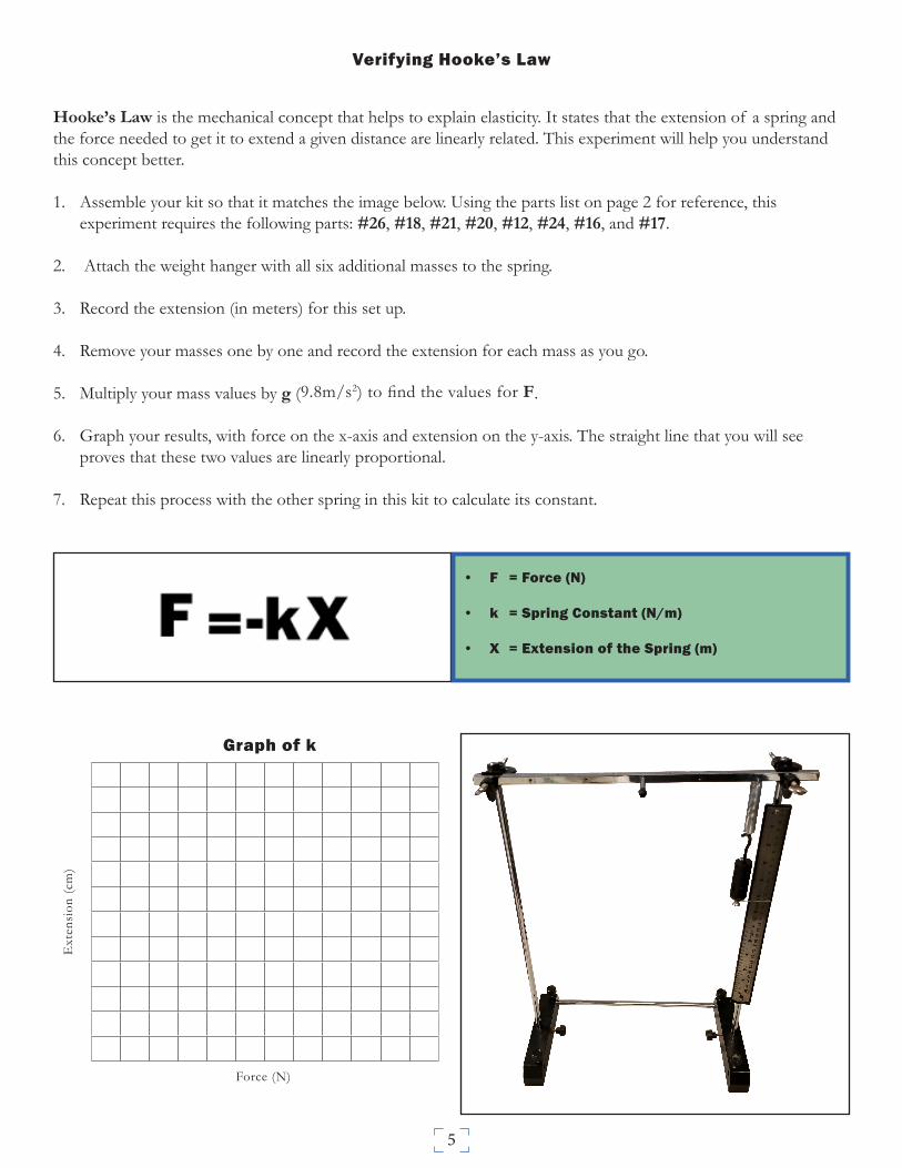
Verifying Hooke’s Law
Hooke’s Law is the mechanical concept that helps to explain elasticity. It states that the extension of a spring and the force needed to get it to extend a given distance are linearly related. This experiment will help you understand this concept better.
1. Assemble your kit so that it matches the image below. Using the parts list on page 2 for reference, this experiment requires the following parts: #26, #18, #21, #20, #12, #24, #16, and #17.
2. Attach the weight hanger with all six additional masses to the spring.
3. Record the extension (in meters) for this set up.
4. Remove your masses one by one and record the extension for each mass as you go.
5. Multiply your mass values by g (9.8m/s2) to find the values for F.
6. Graph your results, with force on the x-axis and extension on the y-axis. The straight line that you will see proves that these two values are linearly proportional.
7. Repeat this process with the other spring in this kit to calculate its constant.
• F = Force (N)
• k = Spring Constant (N/m)
• X = Extension of the Spring (m)
Graph of k
Force (N)
Ext
ensi
on (c
m)

6
Resolving Forces
The force from the dynamometers in this experiment suspend the weight between them in equilibrium. Follow the instructions below to examine the forces at work in the system, even though the is no movement occurring.
1. Gather the following parts: #26, #18, #21, #20, #19, #24, #14, #1, #2, and #17. Assemble the frame using #26, #21, #20, and #19. Fasten a boss head clamp on top of each support rod. Lastly, hang a dynamometer from each boss head clamp and join them together using the weight hanger. (Note: Substituting the weight hanger for the pan and the weight box is acceptable. Testing with different masses between the dynamometers will yield different results.)
2. Set up the protractor so that the center point is at the intersection of the dynamometers and weights. This will involve raising or lowering the rod holding it up, as well as fastening the post into the appropriate hole on the rod.
3. Resolve the horizontal forces by using the appropriate equation below. The values for F1 and F2 can be found on the dynamometers and the angles can be read on the protractor. The values on both sides of the equation should roughly match.
4. Resolve for the vertical forces. The value you find for F3 can be verified by converting your answer in Newtons to grams using F=ma.
For Resolving Vertical Forces
For Resolving Horizontal Forces
• F = Force (N)
• θ = Angle (Degrees)

7
Verifying the Law of Parallelograms
The Law of Parallelograms allows you to add two vector forces together to find out the resultant force. This resultant force will be equal to the mass hanging between the dynamometers.
1. Assemble your kit exactly as you did for the previous experiment using the following parts: #26, #18, #21, #20, #19, #24, #14, #1, #2, and #17.
2. To find θp, use the protractor. (Note: It might help if you line up the line that reads “0” with the left dynamometer so that you can directly read the angle.)
3. Verify the Law of Parallelograms using the formula below. The resultant force R is the force holding up the weight between the dynamometers. By converting Newtons to grams using F=ma, should find that the resultant is equal to the weight held up by the dynamometers.
Law of Parallelograms
• R = Force (N)
• A = Vector Force 1 (N)
• B = Vector Force 1 (N)
• p = Angle (Degrees)

8
Frictional Force on a Horizontal Plane
Friction is the force of resistance between two masses moving against each other. It is represented by the coefficient of friction (COF) μ and is a magnitude of normal force, or the force pressing two surfaces together. On a horizontal plane, normal force is equal to an object’s weight. This experiment will show you how to find the COF on a horizontal plane.
1. Assemble your kit so that it matches the image below. Using the parts list on page 2 for reference, this experiment requires the following parts: #26, #21, #20, #19, #7, #22, #4, and #23. Your wooden block should be far enough back on the plane to observe steady movement without it running into the pulley.
2. Take note of the mass of your wooden block and weight pan. These are the base masses that you will add any additional mass to in the equations below (N=Mg and F=mg). Multiplying mass by gravity will give you weight.
3. Experiment with different masses on top of the wooden block and weight pan. With each mass combination, slightly nudge the block towards the pulley. When the block moves at a consistent pace (no acceleration), take note of the total mass at each end of the thread, and calculate accordingly. Fill out the graph below with each weight combination that causes steady movement. The slope of the graph is the COF.
4. Repeat with the thin side and the sandpaper covered side of the block. (Note: If your sandpaper is worn or not attached, cut and glue a piece to one side of the block.)
Graphofμ
Force to Pull the Block F (In Newtons)
Nor
mal
For
ce N
(In
New
tons
)
• μ =CoefficientofFriction
• F = Pulling Force (N)
• N = Normal Force (N)
• g = Acceleration due to gravity (9.8m/s2)
• M = Mass of the Block on the Plane (g)
• m = Mass Behind the Pulling Force (g)

9
Frictional Force on an Inclined Plane
This experiment deals with the coefficient of friction (COF) just as the previous experiment did. Now, however, the plane is set to an incline. To deal with this incline, you will need to resolve the forces for the equation in the previous experiment (F and N).
1. Assemble your kit so that it matches the image below. Using the parts list on page 2 for reference, this experiment requires the following parts: #26, #21, #20, #19, #18, #22, #7, #4, #17, and #23. Your wooden block should be far enough back on the plane to observe steady movement without it running into the pulley. Position #18 with a boss head clamp, and then rest the inclined plane over it. The hanging plumbob will tell you what angle to use in the equation that follows. (Note: To read the protractor, observe the innermost number being covered by the thread of the plumbob, and subtract that from 90.)
2. Prepare as you did in the last experiment by finding the base masses for the block and for the hanging weights.
3. Experiment with different masses on top of the wooden block and weight pan/hanger. With each mass combination, slightly nudge the block towards the pulley. When the block moves at a consistent pace (no acceleration), take note of the total mass at each end of the thread, and calculate accordingly. Fill out the graph below with each mass combination that causes steady movement. The slope of the graph is the COF.
4. Repeat the experiment using different sides and surfaces of the block, and with different angles.
Coefficient of Friction on an Inclined Plane
+
Graphofμ
Force to Pull the Block F (In Newtons)
Nor
mal
For
ce N
(In
New
tons
)

10
Friction and Acceleration of a Cart
This experiment will wrap up the inclined plane experimenting in this kit. This time, we will be adding acceleration and rolling into the equation. We will find the coefficient of friction (COF) for a rolling object.
1. Assemble your kit so that it matches the image below. Using the parts list on page 2 for reference, this experiment requires the following parts: #26, #21, #20, #19, #18, #22, #25, #4, #17, and #23. Position #18 with a boss head clamp, and then rest the inclined plane over it. The hanging plumbob will tell you what angle to use in the equation that follows. (Note: To read the protractor, observe the innermost number being covered by the thread of the plumbob, and subtract that from 90.) You will also need a stopwatch (#3) and tape measurer (#10) for this.
2. Lightly mark a beginning and ending point for your car when you are observing its acceleration. Measure this distance with your tape measurer.
3. Mark down the mass of the cart and the weight pan/ hanger. Experiment with different masses until you find a combination that causes the cart to accelerate towards the pulley.
4. Position the cart at the bottom of the plane, release it, and time how long it takes for the cart to travel the distance that you marked in step #2.
5. Use the equations below to find the COF for a rolling cart at a certain mass. They are presented in the order they will be used.
6. Repeat the experiment using different masses and angles.
• a = Acceleration (m/s2)
• s = Distance (m)
• t = Time (s)