mechanical vibrations of shipboard...
TRANSCRIPT
●I
MIL-STD-167 (SHIPS)20 DECEMBER 1954
iiFERsEOINGMIL-T-17113 (SHIPS} (IN PART)25 JULY 1952
MILITARY STANDARD
MECHANICAL VIBRATIONS
OF SHIPBOARD EQUIPMENT
1— —
Downloaded from http://www.everyspec.com

\
MIL-STD-167(EHIPS).
20 Dscembsr 1954
IDEPARTMENT OF TRE NAVY
BURSAU OF SHIPSWASHINGTON, D. C.
I MECHANICAL VIBRATIONS OF EHU=OARD EQ~PM~
~MIL-STO-le7(5HIPs)
1. ‘llIJs s!andard has &en approved by tie Burehu of Ships, and Is publlshsd to establish rewUre-msnts for vibrations G4 most Naval machinery and equipment.
I 2. Rscommsndsd corrections, addltlons, or dsletkms should bs addresssd to Chlsf a! the Bureaucd ships, Navy Dqstrtment, Wash~gton 25, D. C.
I
i
Downloaded from http://www.everyspec.com
0MIL-STO-167(SHIPS)‘d) Ikc9mber 1054
CONTENT3
1. SCOPEscope
::: m=1.3 cla5sIficnu0n2. REFER2NCK0 DOCUMENIS2s Speculcaums3. GENERAL REQ~b!EF4TS3.1 Type I - !&irOmsntal vlbratbm3.2 Type U - Inte@y excited Wbra!ban3.3 ‘lYIM Ui - lbrsicmd vibratl.m3.4 Typ IV - LangItudlnal vlbratlan3.5 Type V - Lateral (whipphg) vlb,atlcm
FIGuRES
Figure1 Maximum allowable vjbratlgn2 Static deflectlm of mounttq
TABLSS
l%ble I - Amplitudes cd vlbraUon‘RabLe U - -s 0! correction
‘o
ii
10
Downloaded from http://www.everyspec.com

MIL-STD-167(SHIPS)
20 December 1954 SUPERSEDING MIL-T-17113(SHIPS) (in part)
25 July 1952
MILITARY STANDARD
MECHANICAL VIBRATIONS OF SHIPBOARD EQUIPMENT
Downloaded from http://www.everyspec.com

1“
10MIL-STO-167(SHIP2)20 Oecembsr 1954
MILITARY STANDARD
MECHANICAL VIBRATIUNS OF SHIPBOARD EQIJIPMENT
1. sCOPE
1.1 2c+c- his standard covers the requirements of most naval machtiery and squipment asregards both tn!err~lly excitsd vibrations, and externally imposed vibrations,’ In some specialsqu[pment or installaUons, such as antennas, and large machinery Items, 11may be necessary todeviate from his standard. in such cases, wc’ml modtiications shall k approved by tie bureau oragency concerned.
1.2 Furpo se. - The pu~se of this standard is to aid in the choice of and ensure cmsistency inviliration reguirsments for squiprnent. The bureau or agency concerned should rsfer only to thosesections of this standard applicable to their eguipment, that is, electronic sgulpment procurementspecifications would refer to onh; tyr= I vibration rewiremenw, but P. %cU~@UOII for a diesel Pr@pulsion system may possibly refer 10 types III, IV and V vibration requirements.
1.3 ClassUication. - Mechanical vlbratlon sncountsred on shipboard machinery and sgulpmentshall be chsstfied undsr the following tm.ss:
l’YPS I - Cnvtromental vibration. - l%ls typs applies to all squlpment tntended forshipbaard use, which must be capabIe of wttistavllng the environmentalvtbration conditions which may be encountered atxmrd naval vessels.All squipmeni sensitive to this exciktton should be sub]sctsd to environ-mental vibration tssffi.
TYIM II - Internally cxcitsd vibration. - l%is “typs applies to all rotating machtn=ywhich must operate smoothly from the standpetnt M mechanical sult8-btllty. ‘l%is doss not appty to sultabfliiy from a nofse scmd@nL nordoes it apply to reciprocating mach!mery.
Typs 113- Turstonal vibration. - ‘l%is type applies to all reciprncatfng machtnerytallations as weU as to pmptdsion shafttng systems smpbtng
reductton gears.~ IV - Longttudfnal vibration. - ‘I%ls t~ applies to all proplsfon st@ttng
me V - L&sti ?%&&p&q) vtbraUon. - ‘INS t~ spplies to all turbtne andpropulsion s hafttng tnstallatlons.
2. REFERENCED DCCIJMENT2
2.1 ‘l%e followlnq spectftcattom of the tssue tn effect on date of Invttatton for bids, form a partof this Spectfteatfon:
SPECIFICATIONS
bn3JTARYML-M-17185 - bfounttng, Resillent, Tests for Gene+ ~tfltitlon
(shipboard Appllcatlon).
(CupleS Of SpSctflC8tlon9, st8nd8rd9, drnwtn~s, and ~blkatlons regulrsd by cOn~fOrS ti con-nection wfth spsctfic prc?fsmement functions slmuld bs obtsdned from tbs prccurlng agency or asdlrscted by the conhactbq officer. )
●
Downloaded from http://www.everyspec.com

MIL-3TLs-167(SHIPS)20 Dscembsr 1954
3. GENEFSAL REQtJffiEb4EfiT3
3.1 ‘lJ@s I - Ewircnnwrkal vibration. - ‘1’his prt of the standard rqulres equi~ment b be sub-jected to a slmulatedhwtr onmsntal sib raticm Cdtsnencounlered aboard naval vessels. l%e displace-ment amplitudes and frequencies spscMlsd are consistent wiUI levels at vibration observed on mainstructural members at numerous vessels. Many items of squipment are sutijscted to mors ss~~,~e of resonant mounting arrangements. However, since such resonant installationssre considered abnormsl the aggravated levels of vibmtion are not ussd as a crits$ion. It is~~ecd~d tit **smtiUons, where the amplitudes of vibration am ma+ifisd, w~ld bS c:.r-
l%e ??qulpmsnt would t.%n be subjsctsd to normal hull vibration.
3. 1.1 CefiniliOns. -
3. 1.1.1 Amplitude cd vicmaiion. - AU references to amplitude of vibration in this ssction refer to
%%%%%%% .%~aceme.t cd sinusoidal motion from ths position of r.ss~ or . . . half *.stinguished from velocity or acceleration .smplitude. Amplituds is
total excursicn. Its value 1s exprsssed in plus or minus lnchss or plus or minus rolls (0. 001 Inch).
3. 1.1.2 Rsson.snce is s condition of m~mum magnificaticm of the applied vtbraticn. It isusually manifested by visibly tncr.ssssd vibration of the muipmsnt undsr test. However, a rescmarceof sn btternal componsnt of the squipmenl, wtth no outward manlfestatlon, is also pessible. k thiscass, U the equipment is electrical or electronic, the resnn!mce may be detsctsd by-obsentng someoutput function cd ths equipment, such as voltage or currsnt.
3. 1.2 Environmental vtb=tion. - A!l mschfnery and equipment installsd aboard nsval vesselswili ordinarily .be subject to varyfng frequencies and amplitudes cd vibration, possibly for long psrfod.sof time, during which the machtnery and equipment must continue to perform Its normsl function.FYincipaf cau5es of steady -.ststs shipboard vibration sre (a) propsller blsde exciation, and(b) unbahced forces of PrnPeller and shafthsg. In most vesssls the tibratien frequencies encounteredvsry fmm zero to approxlmatsly 1500 c. P. m. (25 c. P.s. ). h ssveral cd ths Iatsst submarines, sxcit-inq frS.WIenCIeS of UDto ~~ c. D. m. (33 c. P.s. ) are exm?ctsd. The Ssveritv at vibration &m?nds uwm
I --.plitmts, frsqusnc”y, typs of &Ip, and ltitinn of sguipmemt within ship’s ;wucturc. h s&e~ “stssdy-staie conditions, amplitudes of vlbratlon cd as much ss plus or mtnus O. 030 lnchss have beenmtisured at ths bases of vsrious squlpmen=. These maximum ampliuuies and frequencies detsrmineths simulated environmental vibratkm tssts spscifisd tn 3.1.4.
3. 1.3 Basis cd acceptability .- Acceptab,lity will bs conUngent upen the ability of Ute squipmentto withstand tSStS specified in 3.1.4 and the @ilitv to p’rform its princi@ functions duringsmd attsr vibration tes=. Minor dsmage or distortion wffI hs perinfttsd during test providing suchdamage or distortion does not in sny way im~ir the abUity nf the ewipmsnt to psrform Its principalfunctions. Bscauseof the numerous typss of Sqilipment covered by tMs standard, a dsfinite demarcationbetwsen major and minor failures cannot k spscifisd. Therefore, such dscisions must necessarilybs lsft to the judgement of the test engineer. In general, a W faiiure is one which would C?UXmslopsration or malfunction of the itsm of equipment for a long psrlod. NonrepeUUve failures d sklcnparts ss vacuum tubss, condensers, and wiring, which can bs easily replace or repamed sre generallyconsldsred minor fsilures. As such, the repir could bs made snd the test continued, W!I)I no psnaltyto the rema~r of the squipment. ?ometimes the critics! use cd the squipmenl wiU detsrmine theCstegory of failure, that is, a failure nf a component Ln a lighting circuit may bs considered minor.The sane faUure in a reactor controi circuit may k major. Thus, the test engineer or bureau or
1
Sgency concerned shall bs nssponsibie for specifying a major or minor faUure. Unfess otherwiseSpsctfisd, by the bursau or agency concerm?d, the contractor shall repair, at MISowm expsnss, anysnd all damage resulting from UN?b?sts. Failure to tesi tit squipment fn accordance with 3. I. 4txause of unavailability of suitable testbIg machines, does not releass the contrsctnr from’provtdingequipmenl which could withstand the environmsnta.) conditions simtilsd by 3.1.4.
z
a
Downloaded from http://www.everyspec.com

I
I
MIL-3TD-167(sHIPS)
●20 December iWi4
3. 1.3.1 Sxce tion. - ff, in the opinion of the test engineer, there IS any doubt IAat tie eq!.Lp-m.mt under te-tkdactor:!y withstand the tibrat{mco”ditio”sa~l!tifof a period in .?.:.ssof the t!me spectflsd in 3.1.4, this fact shall be tncluded in the official rcpart, required by 3.1.4.4.
3. 1.4 msst procedures.. The test outlined under this section 1s intended to locate resonancesof the equipment and Impose a 2-hour endurance test at the most damagtnq amplitude and frequency.However, th!s test does not constitute an accelera~d Ufe test, in the sense that compliance with thestandard would automatlc~y ensure continuous satisfactory operation of tAe squipmenL
3. 1.4.1 Testinq machine. - Vibration tests shafl b-s made by mean of any testing machinecapable of meettng the conditions spec Uied In 3.1.4.3. Means shall be provided for controlling thedirection cd vibrallon of the testing machine and for adjusUng and messurlng lts frequencies andamplitudes of vtbration m kesp them wtth~ prescribed Iimi=. H the 10wer freW=cY limit of5 cycles per second (c. P.s. ) spectlied In 3. 1.4.3.1 cannot be reached, We available machine may beused uf..m approval of the bureau or agency concerned provided the natu@f frequencies of the equiP-ment tn translational and rocking modes of vibration do not lie below the lowest frequency of theavailable b?sting machine. ‘ll!is may someUmes be determined by bumping the equipment to seewhether iow frequency resonances exist. fn no case shall a vibration testing machtne be used whichhas a minimum frequency greater than 10 c. p.s.
3. 1.4.2 Methods cd aNachment. -
3.1.4.2.1 Shipboard equipment. - For all tests, the equipment shali be secured to tie mountingbracket of the lesting machine in the same manner that itwlil be secured an shj~rd. In caseal:ernate methOdS of MOUtIting are specified, tssts shall bs made using sach mettmd of mounting 6peci-fied by the bu?eau or agency concerned. For squipment designed w he secured to a deck and a head-brace support, a verticai bracket shall be used to simulate a bulkhead. The bracket shall be suffi-ciently rigid to insure hat its motion will be essentially the same as the motlm of the pIatforn of fhsIe:tlng machine. Wlen the equipment is intended to be installed on resilieut mounttngs, these mount-
●ings shall bs provided by the contractor or installing acthnty as appropriate.
3. 1.4.2.2 shipboard portable or test e.qulpment.- Portable or test equipment, which is designedfor permanent or semipermanent attactune.nt to ship siructure shall be attached to the wbra~kmtesting machines in the same maimer it IS attached m the ship. Equipment whtch 1s not designsd forpermanent or semipermanent attachment shall be secured to the testing machines by nie~S bf sult-at,le swaps.
3. 1.4.2.3 Orlentatlon for vibration tesL - Equipment shall be msfslkd on vibration testtngmachtnes in such manner tit the direction Orvibration will be tn turn along each of the URe recU-linear orlen~.ion axes of the equipment as tnstalled on shipboard - vertical, afbwar.shtps, and for6-and-aft. On a horizontal vfbratkan testtng machtne, tie equipment may bs turned 90” fn the hortwntalplane ir order to vtbrate It in each of the two hm-fzontat orientations. At no ttme shall the equipmentbe tnstalled In any other way than its normal position.
3. 1.4.2.4 Resilient mounfinqs. - Wlmn squlpment is to be installed atmard ship on resfllsntmountings, the vtbration tests shall bs performsd with Identical mountfngs attihaf to the equfpment.Unless otherwise spectfied, by the bureau or agency concerned, the mo.mtings shall be fumishad bythe equipment manufacturer. Since mounttngs .sre prfmaruy ued wher. - for shock
-or submarine insfallatlons, the mouritlngs shall have been previouti~~uated in~c=ce wtS@dfication MlbM-17185. Where mountings are to be Government furnished or supplled by tha shlP-bu!lder or tnstallfng actlvtty, tAe equipment manufacturer shali specify the type bf mountings andprovids detail sketches showfng the locations and method of attachment to the equfpmenL
3
Downloaded from http://www.everyspec.com

MIL-3TD-167(3HIP3)29 Dscember 1954
3.1.4.3 Vibration test5. - Each of the tssts outlined herein shall be ?onductsd separately ineach @ the three prfncipd dfrections of vibration. AU tests in one direccion shall bs completsd before~eeding to tests tn another directiom The equipment shall be secured to the vfbratlon table, as specfled in 3.1.4,2 and shall & snergt?.d to perform its nor mat functions. AII amfilltudss of vtbratlon Speci -fisd herein ~e average amplltudss of the vibration table. The tsst shall be discontinued upon evidenceof any failure of the equipmsnt to reset me requirements of 3.1.3. It it is found, necessary to repafrMY damage severe snough m constttuts a fatlure of the squlpment, the entfre tsst shall be repeatsd,unlesg olherwise dirsctsd by the bureau or agency concerned. The manufacturer may, at his ootion.substitute an emtire~y new ‘equipment far retest. ‘If this option is taken, 11 shall bs no~d in the- tsst”
Ireport furnisbsd fn Uxor&tCE with 3.1.4.4.
3.1.4.3.1 EXF40ratory vfbraUon tsst. - To deb!rmfne the presence of resonances in the equip-ment under test, the equipment shall be secured to the vibration table and vibratsd at frsque”ciesfrom 5 c. p.s. (or lowest attainable frsqusncy) to 33 c. p.s. , at a table vibratory amplitude of0.010 plus or minus O. C02 tnch. The change in frequsncy shall be made in discrete frequsncy btter-vnls of 1 c. p.s. and maintained at sach frequency for about 15 seconds. ‘he frequencies at whichresonances c.xur shall bs notd
3. 1.4.3.2 Varialie frquency tsst. - The squipment shall be vibrated from 5 c. p. s. (or 10WI?S:attainsole frsquemcy) to 33 C. p.s., ind screb? frequency interwds of 1 c. p. s. , at the iimplitadesshow in tile I. At each integral frsqusncy, ~e vibration shall be maintafneq for 5 mtnutss.
3. 1.4.3.3 Endurance tssf. - The equipment shall be vibratsd for a total period of at least2 hours, at the resonant frequencies chosen by tie test engineer. U no resonance was observed, thistest shall be psrformed at 33 c. p.s. , udeSS excepted by 3.1.4.3, 4. The tdnplitudes of vibrationshall bs In scccudance with table I.
l%ble I - Amplitudes of vtbratirm.
i Frequency range.; Table amplitude ~(c. P.s. ) ; plus or minus inch ;
5t015 ; 0,030+0.006 ii6t025 : ,0207 .004 :26t033 : .010: .C02 :
3. 1.4.3.4 Exception. - ~uipment intsndsd for tnslalUation on a articu”mr class of vesssl,-+-need not be vibrated at the frequsncy range higher than tne exciting frequency o the vessel. For
example, !f squjpment is to bs imstalled cm a vessel witi a maximum exciting frequency of 18 c. p. s.,tAe saulpment has to be vibratsd at only the first two ranges shown in table 1.
: 4.4 Test report. - ‘l%e tssl rEPX’t to be furnished me bureau or agency concerned by thetestii,, laboratory shall include detailed descriptions of any &macje or malfunctioning incurred md awhat stage in the tests it occurred. When possible, photographs of physical dn!mage shall be tnclude,Rscommen&tions are &sired as to whst corrective measure, if any, should be takem At the dis-cretion of the test engineer, it shall also include other pertinent information, such as the overalldimensions of the squipment, its weiqht, approximate location of the centsr of gravity, and a sketchor photcqraph of the methods used in mounting it on the test machines.
●
4
I
I—-
Downloaded from http://www.everyspec.com

MIL-STD-167(SHIPS)20 December 1954
i-
3, 2 TYW n - Intermlly excited vibmtion. - Tliis section of the s!k+ndard covers the balance andvtbration requirement~ to be specified in the procurement of new machLaery. l% llmifations Setforth herein may aiso be used as criteria on overhaul tolerances, but should not constitute a criterionfrm the need for overhaul, that is, if a turbo-generator set.is vibrating PLUSor mbms 10 mtls itwouLd be obvious that m overhaul would be in order. LIIsuch case, fhe balance and vibration toler-ances of fhis standard may M used as overhaul tolerances, but U the turbo-generator set is vibratingat a level slighLly akwe the cwve of figure 1, it need not be removed for overhaul, merely becausethe level exceeds the curve value.
3.2, 1 DefinitiOns. -
3,2. 1.1 Static balance of a rotating body exisLs when the center of gravity of the body lies on theromtional axis. A smtic unbalance results in a force unbatance which tendss to displace fJe bcdy fromits axis of rotation. Force unbaiancc can be corrected by single-plane correction,
3. 2.1.2 Dynamic balance of a rotating body exists when the summatim of the momenis about thebearings equal zero. A dynamic unbalance results in a moment wh,ch causes a rotatLng bcdy tooscillate akmut an inert!a axis perpendicular to its axis of rotatmn. Wlen a body ha8 a dynamic ormoment unbalance, it can be satisfactory removed only by two-or-more plane correction. When abody is in dynamic bah.nce, it is also in static balance.
3. 2.1.3 Correc..ion phanes.- A correction plane is one perpendicular 10 tie tis of rotation ofa body, wiLhin which plane weigfits are added m’ removed in or&r to reduce unbalance.
3, 2.2 Basis of acceptability .- AU rofating machinery shalt be balanced 10 mbimize vtbr~flon,bearing wear, md noise. ‘l%e types of correction, as shorn in table 11 shali depend or the speed ofroLXion and relative dimensions of the rotor.
‘l%ble 11- Types O! correction.
L.engLh/dkmete? : Speed r. p, m ; Type of correction ;
~ Less than 0.5 : C-1CU30 : One plane (static): Greater than 1~ TWO Diane (dynamic) ~
~ Greater than O. 5: 0-150 : One plane (static) :: Greater than 150 : ‘TWOplane (dynamic) :
1The iength and diameter refer to dimensions of rotor mass,exclusive of supporting shall.
3, 2,2.1 The limits of allowable unbalance shall conform to 3.2.3.2. In addition, tie limits ofvibration shall conf?rm to figure 1. The method of appiylng balance correction shall be designated inUw specifica~on covering the pariiculw piece of equipment.
3. 2.3 Procedure. -
3.2, 3. 1 bala.ncinc methods. - Except for machinery operating below 150 r. p. m. , all bahmcingshall be accomplished by means of balancing equipment which requires rcdatban of the work piece.‘This maj’ be either shop or portable type bakmcimg equipment. The minimum detectable unbalance ofthe bxl.mcinq machine used shali be below the rzsidual unbalance specified by 3.2.3.2. For machtneryrhled at lower than 150 r, p. m, , the rotor may be balanced by symmetrically suppertinq the rotor ontwo knife edges and upplylng correction to attiin a static balance.
b
1.
Downloaded from http://www.everyspec.com

1’
M3L-2TD-16Y(2HIP3)Zl D9cembar 1954
3.2.3.2 Balance limits .- When baiemced tn accrdance wltJI 3. 2.3.1 the residual unbalance, ineach plane of correction, of any rotattng part sbalf no! exceed the value determined by:—
U . ~wfor speeds h excess of lCOO r. P. m.
or u . 5= for speeds between 150 r.,p. m. and IWO r. m m.
or U -0. 25W for speeds beluv 150 r.p. m.where U - maxfmum allowable residual unbalance In oz.-inches
W - weight of rotat.tng part in @ridsN - maxtmum operating r. p. m. 31 unit
3. 2.3.3 Vlbratlon test. - When mounted as Spectfled in 3,2. 3.3.2 and measured in accordancewiL\ 3. 2.3.3.3 , the residuai vibration ampllfude shall not exceed ‘he values shown on figure 1. Inmost machinery, tha residual Vlbraticm wUI be prtnclpally at rotational frequency (first order). [nUIese cases, Ute measurement may be Ilmlted to the evaluation at first order vibration only. In thecase cd complex machtnery, which !nclude reductfon gtig, impellers, or other vi brat!on exciting-es, It 1s expected that higher orders of vfbratton -y ex!st. w such cases, measurements mustindicate that either: . .
(a) T%e overall vibration veloc!ty level Is less than plus or rhtnus 0.3 !nc!I/secwtth a maxtmum a!lovable dispkcement of plus or minus 2.5 mUs, or
(b) Thw dIspt8cement amplitudes at all Comwncnt frequencies shall fall below thelevel of figure 1.
3. 2.3.3.1 ‘he procurement s~iflcatlon for the item of equfpment shall specify whelAer vibralio”measurements may be limlb?d to f!rst order, or be extended to cover higher orders. In general,machtnery such as motors, generators and simple rotating devices wltJI”no gears would have a princi -@ vlbratton of only first order. Machinery such as g- driven unlk% units ylth tnternal gearing,rotary cumps or compressors and fans and blowers would often Pavs higher orders of vibration, inaddition tb the firs: order.
3. 2.3.3.2 Mounttng.- After baianclng, the unit stall be comclet.ely assembled and, U practicable,mounted elastically at a natural frequency less than one-qwter of tie minimum rotatiomd frequency ofuntt. To accomplish this, the minimum Static deflection of the mowntng should be deiermtm?d byfigure 2, but In no case shall the defleci ion exceed one-half the Ortginal height of the elastic element.On machfiierj that cannot M mounted as described, the unit shall be mount~d on a fc.undation the sameas, or COmIDenSUIU& wtth, the shipboard Moullng for which !1 is Intended, unless otherwise approvedby the bureau o? agency concerned.
3. 2.3.3.3 _~ements. - On all machinery except turbines, amplitudes of vttration shall bemeasured on the bearing housing tn the direc:ion of maximum amplitudes. In the case of turbines,smpl{tudes of vlbratkm shall be measured on the rotatiug shaft, adjacent to the bearings. Care shouldbe exercised to ensure that the shaft is 3m001h and concentric. F.ccemriclty cd shaft or high spots onthe shaft may easUy result tn erroneous readings. Amplitudes cd vib~t!on Shall be held %lthln thelimits shown on figure 1. On consbmt speed units, measurements shall be made ai the omrating speed.In tJe caw of =-lable speed units, measurements shall be made at maximum speed and at all criticalsF==xJ9 within owrattmg range.
3.2.3.3.4 fn struntmtE. - Amplltude and frequency measurements shall be made wttk a sul’ablevtbratlon instrument tith a sensitivity consistent wtlh the amplitude and frzquency specified byfigure 1.
6
Downloaded from http://www.everyspec.com
I
.
MIL-STD-167(SHI=)24 Dscembw 1954
3.2. 3.3.4.1 When it is known that a unit 1s vlbraltng at Principdiy one frSWSnCy, any of fitsfoliowing tws of instrumentation wouid suffice:
(a) Beam lYPS vlbrornetsr, such as Davey, or Generai E3sctrfc.(b) Vibration metsr, such as MB, C!aildyne, or Consolldatsd.(c) Mechanical rscording vtbrograph, such M Askarda, Cenerai Elsclric or
Westinghou~.(d) Reed type frequency vibrometsr (this would be necessary i! the vibrstion
instrument .ssd doss not af50 dsffne the frsqusncy).
3. 2.3.3.4.2 fn the cass of more complex equipment the foilowing types of fn..LrumenLatiun wouidbs necessary:
(a) MschnicaI r-rdtw ~brwwh, such = A~@ Geiger, G*-~ ~=~icor Wssttnghouss.
(b) Electronic vibration meter, such as MB, Cafidyne, or Ccrnsoiida:ed, tcqetherw;fh osciiioscops, rscording dsvice, or frsqusncy analyzer.
3.2.3. 3.5 Exce tion. - In tie case of complex machinery itsms, such as assemblies employingreduction gears,~e~mble amplitudes shownonfigure 1 may be tc.a high for propsr apsration cd
Itie equipment. In such case, aliowable amplibidss based on mamufacturtng tolerances and clearances.and operatioIai rsquiremsnts, wIII be spscifisd by the bureau or agsncy ccmcerned-
3.3 Type 111- Torslonaf vibration. -
3. 3.1 Osfinitions. -
,03. 3.1.1 Msss el~=tic system. - The rm.ss siastic systsm is dsfined as fhe squivaknt osciUalirg
system which retaiis as ciosely x Pssible the dymmic cha.ractsristics o! the =tual sysf.sm. l%issquivakmt system consists of a ssries of mass moments of inertia of routing and reciprocating sie-men:s interconrectsd by torsionally flexible eLements. Auxiliary drive eiements such as camshafts,~mps, and blowers, are as much a part of the m&ss eiastic system as are ths shafting, COUFMWJS,and masses of the main drive eiements.
3. 3.1.2 Torsional vibration .- A torsionai tioratton is a vibration that is cbaIWXSrIZfM byan@= dfsplacemm: of tie mass elastic systsm relsttve to its axis of rolaticm
5. 3.1.3 Vinratory amplitude .- Vibrafory amplitude is fhat angdar displacement induced by thetors!onal vtbration of a mass elastic systsm.
3. 3.1.4 Vibratory torque .- Vibratory torque is that tor,ue inducsd by the torsional vibration o!a mass elastic system.
3. 3.1.5 Vibratory s&ess. - Vibratory swess is tit stress induced by the torsionat vibration ofa mass elsstic system.
3. 3.1.6 Mode.- Mode is the manner or pattsrn of vibration ad is describsd by its natural f re-quemy and re=amplitude curve.
3.3, 1.7 Node. - A node is a pint of zero vibrabxy amplitude.
3.3.1.8 Ordsr. - Order is tie numbsr of cycles of vibration occurring during sach revolution 01tbe refersnce shaft.
‘o
I
Downloaded from http://www.everyspec.com
LUL-STD-167(SHIPS)~ Decemhr 1954
3.3.1.9 Operating spes d range. -
(a) For a constant spsed unit,overspsed tilp setting.
(b) For a w=!able speed unit,
the operating speed rage is from SO P¢ to the
the operathg speed range is 80 percent of mtnlmurnoperating speed to the overs~”ed trip Settfng, unless otherwise sp?cif led,by the bureau or agency concernsd.
3. 3.2 Basis of acceptability. . Acceptability of the 5ystsm 1s contingent upon camplfance with ther~,lirementS Srecified herebh
3. 3.2.1 Limi&- The mass elastlc system shall have no excessive torsional vibratory stressesbslow tJe top operating speed Of the unit nor excessive vibratory torque across gears witiin theoperating range of the unit. fn no ca.ss, however, shall the amplltwie of torsional vfbration be suffi-cient to adversely affsctOPeratiun of the unit or its synchronization wtth other un!t.s, as b the case ofgenerator sets.
3. 3.2.1.1 Stresses wfthln spe ed range. - Wlthln the o~ratIng spsed range, excessive torsloml~.b~tory stress is that stress tn excess 0~ where, for
stssl & - ~==me .dfofiast iron 0, Mm, rmtsrfd
sv- Torsfon.4 Fatigue Llmlt. ff fatigue tssts have been conducted on full-scale8
spectmets of the material csod, then the contractor may use ~ . 1,/2 Torsional Fatigue Limit as thelimittng permissible stress. The source of the fatigue limit value and, K requested, the fatigue test&a, shall be repor:ed to the bureau or agertcy concerned.
3. 3.2.1.2 Stresses below speed rage. - Beiow the op?rating speed range, excessive lorsionrdvibratory stress 1s hat s!ress in excess of ~-3/4 times the % vaiue given in 3.3.2.1.1.
3.3.2. 1.3 Torque. - For diesel installations excessfve vibratory torque, at any operattig spsed,is that vfbratory torque greater thm 75 percent cd the driving torque at the same speed, or 25 percentof full Ioad torque, whichever is smaller. In the case of turb!ne drfves, only 10 per.:ent of full loadtorque is allowed fnstead of me aforementioned 25 percent.
3. 3.2.2 Mathematical analys! s.- A complete mathematical ‘anaiysis. indicating probatde compli-ance with the iimlts of 3. 3.2.1 shal 1 be submitted to the bureau or agency concerned for approval,prior to construction of the unit. These calculations should be prepared by engine buflder, designsgent, or shlpbulldar as rsquired by the contract or order. Approval of such mathematical amdysfs,however, wffJ net release tie contractor from the respansibllity cd proving conformcmce by actuallytors;ographing assembled units.
3. 3.2.2.1 Description of wra~.%ls. - The mathematical analysis shall tnclude:.—
(a) A cfescrlptlon of the systsm relating btformation psrtinent to analysis such asoperating speed range, gear rattos, and name plata data.
(b) A labeled assembly dmtwlng showtng arrangement pf the elements in the unitand dimensions IX shaftfng.
(c) A labeled line dfagram of the mass elastlc system indicating values of massesand stfffnesses, ‘mcludfng basic as-sumptf on, where applicable.
(d) Natural frequencies of all Important modes of vibration.
●
I 8
Downloaded from http://www.everyspec.com
MU-6TD-167(2EIPS)‘Z1 Dssembsr 1Q54
(e)
(f)(d
For sash mode, stxess F-= dsgrea (or Fer rsdian) CdCtiU~S fOr the mO~hfgirly sdxessed sections of sbaittng. ‘l%e calctdattan strsll indicate thesections at which tie maxtmum stresses sxfst.
Rstative srnplitude curves (mcde shapas).Estimates of all important vibratory amplitudes, stresses and gear torques d
the unit tnchding cslculattons and sssumpUons used us make the eatirnatss.
3.3. 2.3 Torstonal vibratton tssts. -—
3. 3.2.3.1 Normal tssts. - ‘1%wove compliance with the limits of 3.3.2.1, a torsional slbrattontsst of a ccmplete unit shall bs conducted snd a tsst repert shall be submitted to the bureau or agancyconcerned for 8P?Iroval. Unless otherwise ~ctfied, in tne aquipmsnt spectficatlons all sleruents ofthe complete unit M ba incUJded !-n the tsstsd unit. Bassd on the results d mathematical anslysis(see 3.3. 2.2) the tors:ograph tsst may ba waived by the bursa..
3. 3.2.3.2 Simulated ins~lgtion tssts. - A torsional vibration test, on a t8st stand insta.llattrm,slmutating the actual shigboard installation, may be psrmlttsd provtdsd thst a mathematical snalysi9(see 3.3. 2.2) of the test stand installation be submitted.
3.3.2.3.3 Auxillsry branches. - Whsn specified or when rsquested by the buraau or agsncyccncenred aftsr receipt of the xtmt!!ematlcai analysis, torslcmal vibration tasts shall be made of theauxtltury drivsn slements, such as blowers and preps.
3. S. 2. 3.4 Instrumentation. - Suitable instrumentation, consistent with the amplltudss and fre-quencies 2ntici@sd, s id bs used for a13 torsional vtbration tasting.
3.3.2. 3.5 Report. - ‘l%e tsst report shall !nclude:
(a) A descriptim of the installation and tsst conditions, including such matsrial asr.amepiata data, opsrattng spssds, and loads.
(b) A description of tastr.msntation uttlizsd and locations cd mesauremi. .lts.(c) A graph, plotting amplitudes versus r. p. m. for all important ordsrs of
vibration. PDin:.% are to bs plottsd at suitable increments, from as lowa spesd as possible tm top opsratfng spsad to ckarly detie a.11critlcam.
(d) fbfa.xim.m vfbratory shaft stresses and vlbrabmy gear torquss encounteredshall be determined.
?.. 4 Typs IV - L.cmgttudnal vibration. -
3. 4.1 Definitions. -
3. 4.1.1 Longitudinal vibration. - I.ongitudlnal VIDIWlOn is a vfbraUon charac+=rized by linasrdisplacement 0! the major slemsnts in an axtsl drsctlon.
3.4.1.2 MS OkIst!C SYStSrD. - Mass alasttc sYstam 1s tie Squlvalent oscfflating system whichretafns as closely as possible the dynamic ctwractsristlcs of the actuat system. This aqulvalsntSystam consists of ~ masses as the propeller, thrust king, md reduL.UOn gem, ~tsrc_~~by the flexible elements of shafting and foundations.
3. 4.2 Basis of acceptsbUity. -
3.4.2. ] Mathematical adysis.- A complets mathematical analysis cd the longitudinal vlbratctrycharacteristics of the zmtss slastic syrtem .sAall be submitted to Lhe bureau or agsncy concernsd foraPPrOvaL All ma= slastlc factors and sssumed foundation slast.tc COIIStaMS shall ha CI_lY SIIOWO.These analyses shall clearly demonstxats that ‘tie prcqmlslon systam is free from any longttudindcritical in the rage of 50 to 115 percent of maximum r. p. m. , unless otherwise approved by tiebureau 0., agexy conce~ed.
9
Downloaded from http://www.everyspec.com
bfrL-m-167(SHXPS)211IMcembsr 1954 ●
3.4,2.2 Limit. - If Um matbsmatlcel analysls Indicates the presence of a crltlcnl below 50 per.centcdmaxim~p. m. , vibration measurements shall be made to detsrmtne tie maximum ampli-t~es ~ vib~tI~. A V$tem s~l & considered acceptable OnlY U the amplitudes of ylbration at thecritical spesds sre of such amplltude and phase as to be nondamaglng to the gears and thrust bearings.
3.5 ~ V - Lstsral (wh[pptngl vibraUon. -
3. 5.1 DefinltlOn. -
3. 5.1.1 Lab?ml vibration. - IASIU1 vibration 1S the vfb~tory deflsctlon of a rotating shaft In adlrectlon transverse to the @s of roiatlon.
3. S. 2 Bas19 of acceptsbUlty. -
3. 5.2.1 Mdhsmatlcal analyses. - A complete mathematimi armlysls of the lateral vibratorycharacteristics of the rotating system 9hall be suhmittsd to the bureau or agency concernsd for appro-=1. l’hls snalysls shall clsarly demmmtnte ttmt the system 1s free from any lateral crlticai below115 percent af the maximum ratsd speed unless otherwise approved by the Mreau or agency concernsd.
NfYTE: Type I of this standard supersedes that part of SPectflcatton MfL-T-17i13 covering vibmtion.
Copies of speclflcatlons, stnndnrds, drawings, and publications requirsd by ccm&actors in con-nection wiL> specific procurement functions should bs obtatned from the procuring agsncy or asdlrscted by the contracting officer.
Copies of MS standard for mllitsry use may be obfatned as Indicatsd in the foreword to tAeIndex of Military Spsciflcat!ons and Standards.
Both the tiUe and ldsntifying symbol numBer stmuid be stipulafsd when requesting copies ofmiiltdry sisndardm
Custcdiam
Burasu of 911PS
10
L
Downloaded from http://www.everyspec.com
.
a
g 0.s0 I I I 111111 / I !I /-
=j 0.10
: 0.00
0 O.oa
0.04
0.0s
O.oa
0.01
..*. :
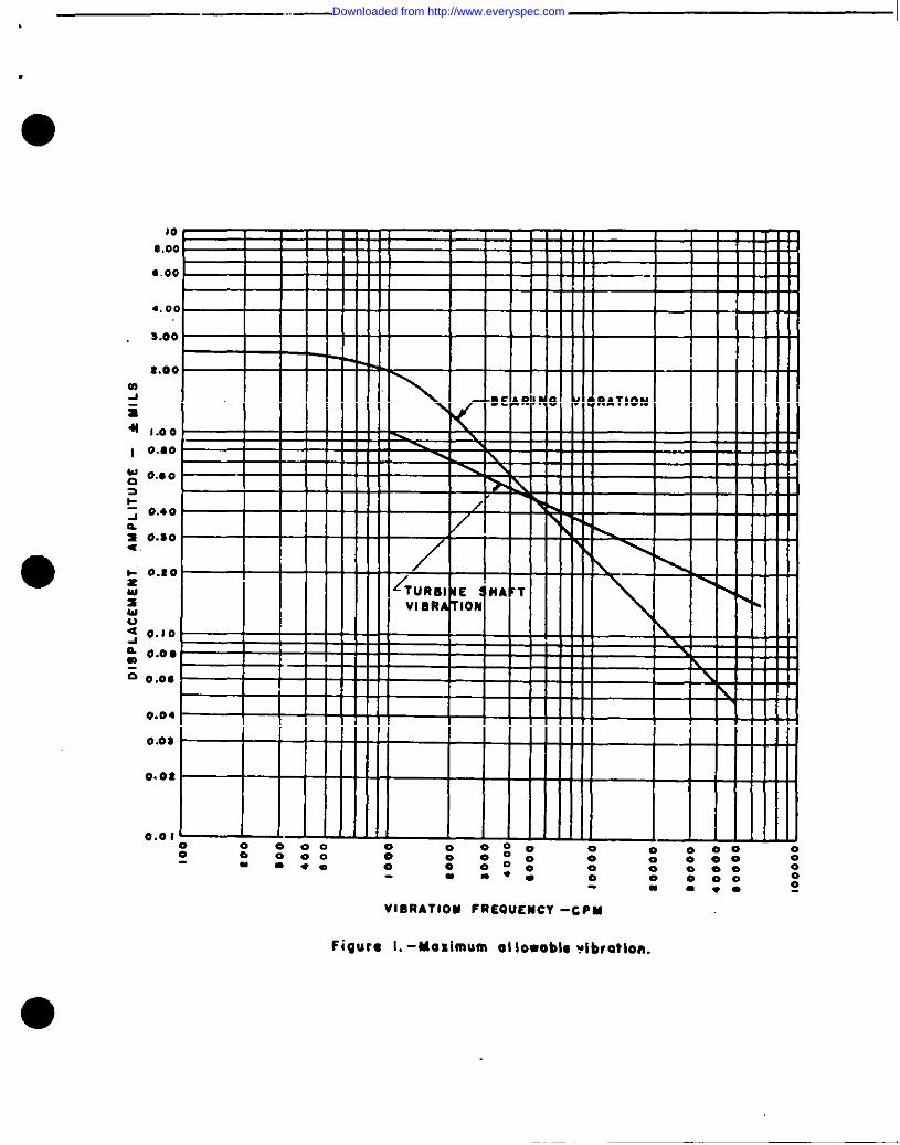
VI BRATIOU FREQUENCY -Cpu
Figure 1.- Maximum al {Owoblc ufb,otlo”.
Downloaded from http://www.everyspec.com
I
I .I
●1.0 , J I ,
Oao 1
O.*O I
0.40
0.s0
0.10
0.10
O.o#
g 0.0, -
si 0.04
g 0.0s
z# O.oz
8
g
2 0.0 I
h .00*
.006
.00*
.00s
.eot
.001 ~0000
0 0 0-“ :*-
0 0 eoo0 0 0000 00
: :**
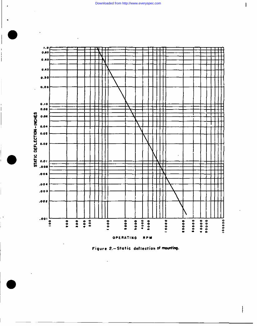
OPERATINO RPM
Figure 2.- Stotic deflection Of mti.
II_
Downloaded from http://www.everyspec.com