mechanical testing on welded pipes
TRANSCRIPT

MECHANICAL TESTING ON WELDED PIPES
Yeo Cheng Chuan
Bachelor of Engineering with Honours
(Mechanical and Manufacturing Engineering)
2010
UNIVERSITI MALAYSIA SARAWAK
R13a
BORANG PENGESAHAN STATUS TESIS
Judul: Mechanical Testing on Welded Pipes
SESI PENGAJIAN: 2009/2010
Saya YEO CHENG CHUAN
(HURUF BESAR)
Mengaku membenarkan tesis * ini disimpan di Pusat Khidmat Maklumat Akademik, Universiti
Malaysia Sarawak dengan syarat-syarat kegunaan seperti berikut:
1. Tesis adalah hakmilik Universiti Malaysia Sarawak.
2. Pusat Khidmat Maklumat Akademik, Universiti Malaysia Sarawak dibenarkan membuat salinan
untuk tujuan pengajian sahaja.
3. Membuat pendigitan untuk membangunkan Pangkalan Data Kandungan Tempatan.
4. Pusat khidmat Maklumat Akademik, Universiti Malaysia Sarawak dibenarkan membuat salinan
tesis ini sebagai bahan pertukaran antara institusi pengajian tinggi.
5. ** Sila tandakan ( √ ) di kotak yang berkenaan
SULIT (Mengandungi maklumat yang berdarjah keselamatan atau kepentingan
Malaysia seperti yang termaktub di dalam AKTA RAHSIA RASMI 1972).
TERHAD (Mengandungi maklumat TERHAD yang telah ditentukan oleh organisasi/
badan di mana penyelidikan dijalankan).
TIDAK
TERHAD
Disahkan oleh
(TANDATANGAN PENULIS) (TANDATANGAN PENYELIA)
Alamat tetap:
Lot 55, Kampung Lopeng, 98000 Miri, Ir. Dr. Mohammad Sharil Osman
Nama Penyelia
Sarawak.
Tarikh: Tarikh:
CATATAN * Tesis dimaksudkan sebagai tesis bagi Ijazah Doktor Falsafah, Sarjana dan Sarjana Muda.
** Jika tesis ini SULIT atau TERHAD, sila lampirkan surat daripada pihak berkuasa/organisasi berkenaan dengan
menyatakan sekali sebab dan tempoh tesis ini perlu dikelaskan sebagai SULIT dan TERHAD.

APPROVAL SHEET
Final Year Project attached here:
Title : Mechanical Testing on Welded Pipes
Name : Yeo Cheng Chuan
Matric No. : 17579
is hereby read and approved by:
Ir. Dr. Mohammad Shahril Osman Date
Project Supervisor
MECHANICAL TESTING ON WELDED PIPES
YEO CHENG CHUAN
Thesis is submitted to
Faculty of Engineering, University Malaysia Sarawak
In Partial Fulfillment of the Requirements
For the Degree of Bachelor of Engineering
With Honours (Mechanical and Manufacturing Engineering) 2010

i
Dedicated to my beloved family and friends
ii
ACKNOWLEDGEMENT
I would like to take this opportunity to express my sincere acknowledgement to
all parties and individuals that give me highly support and guidance throughout the
periods of completing my final year project.
First of all, I would like to express my deepest appreciation to my supervisor, Ir.
Dr Mohammad Shahril Osman, for his excellent supervision, encouragement and
support throughout this final year project. With his advises, experience and ideas, I am
able to solve the problems that I faced during the project.
A special acknowledgement goes to my family for their motivation,
encouragement and support along the way to accomplish my project. Last but not least, I
am very thankful for my friends and the Mechanical and Manufacturing Engineering lab
assistants who have given me lots of help and support. Thank you for always being with
me during these years until my completion of this bachelor degree in Mechanical and
Manufacturing Engineering in UNIMAS.

iii
ABSTRAK
Pengelasan memainkan peranan yang penting dalam banyak industri terutamanya
pengelasan paip dan sambungan las telah menjadi salah satu kaedah yang paling penting
terkini. Oleh sebab itu, adalah penting untuk memahami sifat mekanik sambungan las
untuk paip sehingga paip las dapat dilaksanakan secara berkesan dalam pelbagai jenis
industri. Tujuan daripada projek ini adalah untuk menyiasat kekuatan paip telah dilas
yang ditentukan oleh ujian mekanik berdasarkan Standard Kod ASME. Ketegangan
ujian dan tiga titik uji lentur dilakukan untuk Karakterisasi sifat mekanik sambungan las
paip. Keputusan paip dilas dan paip logam asas yang kemudian diinterpretasikan dan
berbanding dalam hal kekuatan, strain, dan beban maksimum sebelum kegagalan contoh
uji untuk membezakan dan menyiasat pengaruh paip logam asas selepas dilas.
Keputusan dan analisis menunjukkan bahawa paip yang telah dilaskan memiliki
kekuatan yang lebih tinggi sedikit daripada paip logam asas dalam kedua-dua ujian
mekanik. Pipa logam asas menunjukkan sedikit peningkatan simpulan selepas dilaskan
tetapi telah dikurangkan daktilitas. Secara keseluruhan, berdasarkan hasil kajian
menunjukkan bahawa sambungan las adalah sebagai kuat, atau bahkan lebih kuat dari
paip logam asas dan mempunyai perilaku mekanikal serupa dengan paip logam asas.
Kajian juga menunjukkan bahawa persiapan sambungan las yang tidak tepat akan
melemahkan kekuatan paip dilas dan gagal lulus ujian mekanik.
iv
ABSTRACT
Welding plays an indispensable role in many industries especially the pipe welding
and welded joint has become one of the most important joining methods available
nowadays. Hence, it is essential to understand the mechanical properties of the welded
joint for pipe so that the welding pipe can be applied effectively in various kinds of
industries. The aim of this project is to investigate the strength of the welded pipe which
is determined by mechanical testing based on ASME Standard Code. Tension test and
three point bending test are conducted to characterize and gain greater understanding of
welded joint mechanical properties and quality. The results of the welded pipe and base
metal pipe are then interpreted and compared in terms of strength, strain, and maximum
load before failure of test specimen to differentiate and investigate the effect of base
metal pipe after being welded. Results and analysis indicate that the welded pipe has
slightly higher strength than the base metal pipe in both of the mechanical tests. The
base metal pipe shows a slightly increase of stiffness after being welded but has been
reduced in ductility. Overall, based on the results, it shows that the welded joint is as
strong as, or even stronger than the base metal pipe and has similar mechanical behavior
with base metal pipe. The experiment also shows that the improper preparation of
welded joint will weaken the strength of the welded pipe and will cause the failure for
passing the mechanical testing.
v
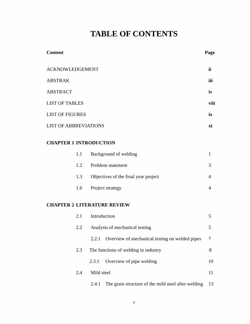
TABLE OF CONTENTS
Content Page
ACKNOWLEDGEMENT ii
ABSTRAK iii
ABSTRACT iv
LIST OF TABLES viii
LIST OF FIGURES ix
LIST OF ABBREVIATIONS xi
CHAPTER 1 INTRODUCTION
1.1 Background of welding 1
1.2 Problem statement 3
1.3 Objectives of the final year project 4
1.6 Project strategy 4
CHAPTER 2 LITERATURE REVIEW
2.1 Introduction 5
2.2 Analysis of mechanical testing 5
2.2.1 Overview of mechanical testing on welded pipes 7
2.3 The functions of welding in industry 8
2.3.1 Overview of pipe welding 10
2.4 Mild steel 11
2.4.1 The grain structure of the mild steel after welding 13
vi
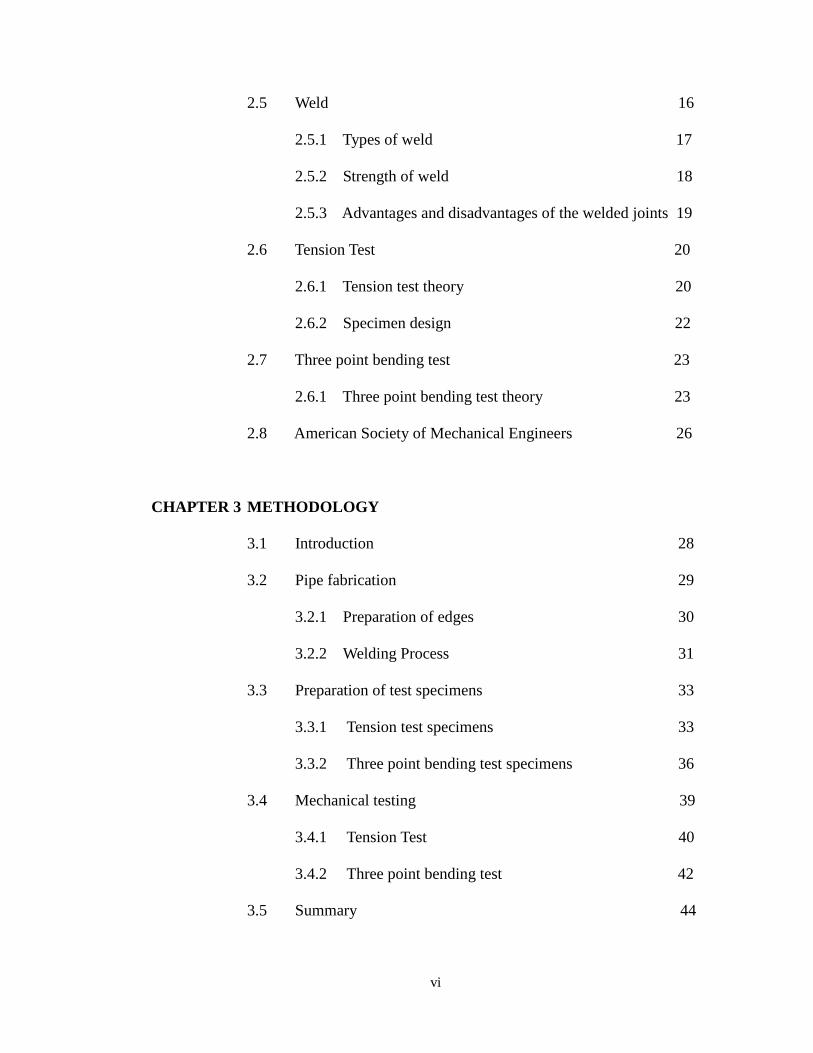
2.5 Weld 16
2.5.1 Types of weld 17
2.5.2 Strength of weld 18
2.5.3 Advantages and disadvantages of the welded joints 19
2.6 Tension Test 20
2.6.1 Tension test theory 20
2.6.2 Specimen design 22
2.7 Three point bending test 23
2.6.1 Three point bending test theory 23
2.8 American Society of Mechanical Engineers 26
CHAPTER 3 METHODOLOGY
3.1 Introduction 28
3.2 Pipe fabrication 29
3.2.1 Preparation of edges 30
3.2.2 Welding Process 31
3.3 Preparation of test specimens 33
3.3.1 Tension test specimens 33
3.3.2 Three point bending test specimens 36
3.4 Mechanical testing 39
3.4.1 Tension Test 40
3.4.2 Three point bending test 42
3.5 Summary 44
vii
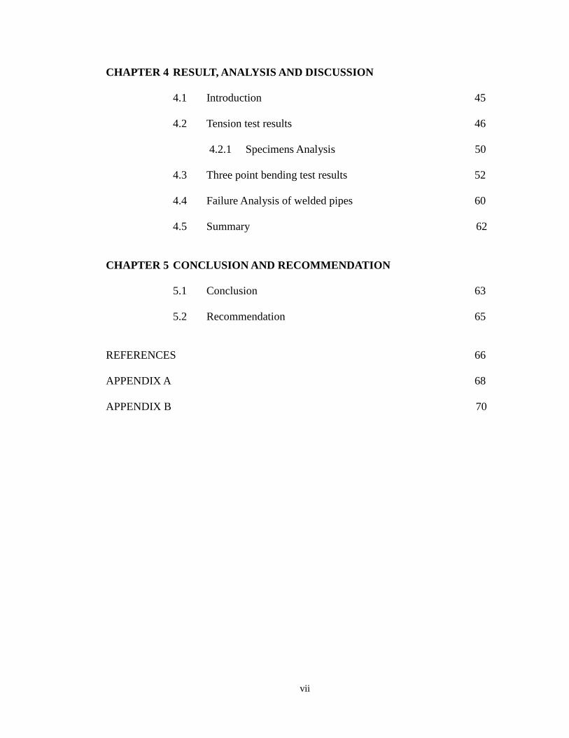
CHAPTER 4 RESULT, ANALYSIS AND DISCUSSION
4.1 Introduction 45
4.2 Tension test results 46
4.2.1 Specimens Analysis 50
4.3 Three point bending test results 52
4.4 Failure Analysis of welded pipes 60
4.5 Summary 62
CHAPTER 5 CONCLUSION AND RECOMMENDATION
5.1 Conclusion 63
5.2 Recommendation 65
REFERENCES 66
APPENDIX A 68
APPENDIX B 70
viii
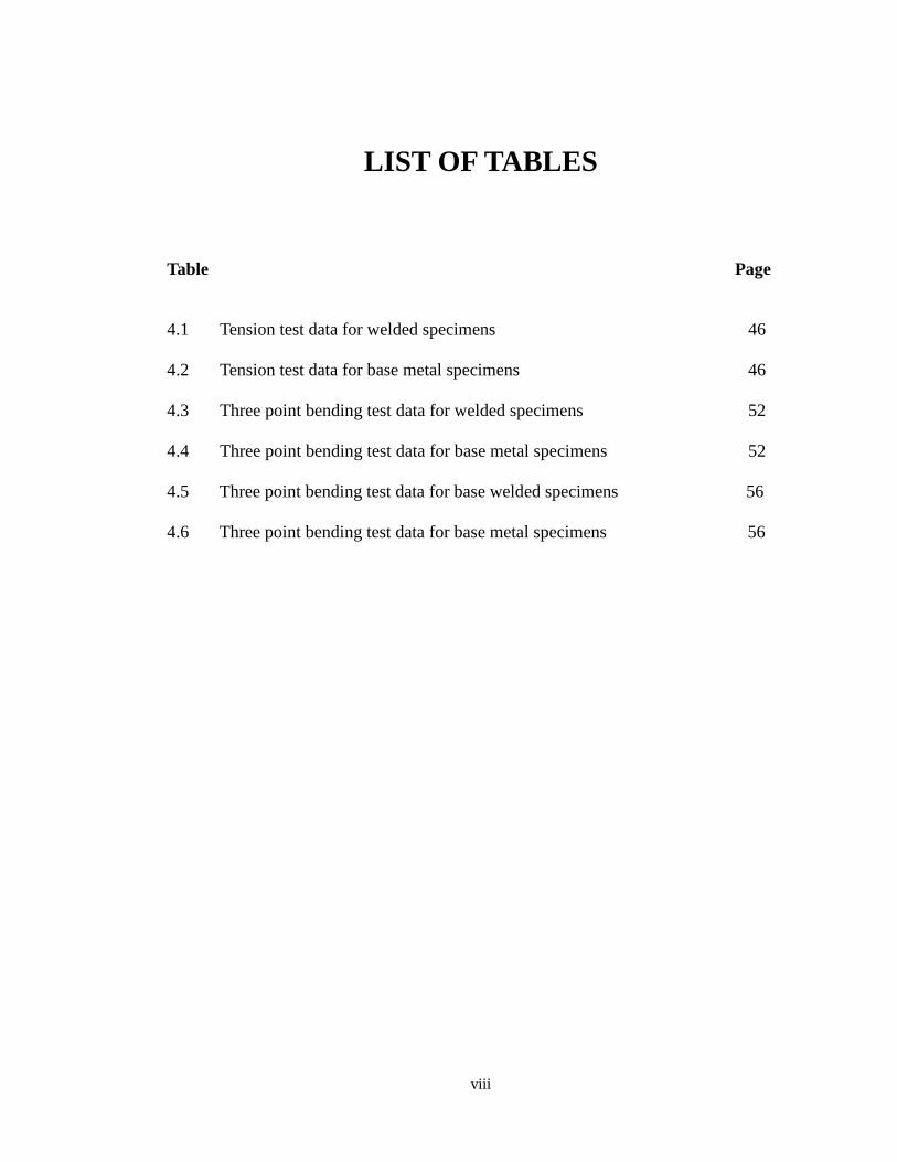
LIST OF TABLES
Table Page
4.1 Tension test data for welded specimens 46
4.2 Tension test data for base metal specimens 46
4.3 Three point bending test data for welded specimens 52
4.4 Three point bending test data for base metal specimens 52
4.5 Three point bending test data for base welded specimens 56
4.6 Three point bending test data for base metal specimens 56
ix
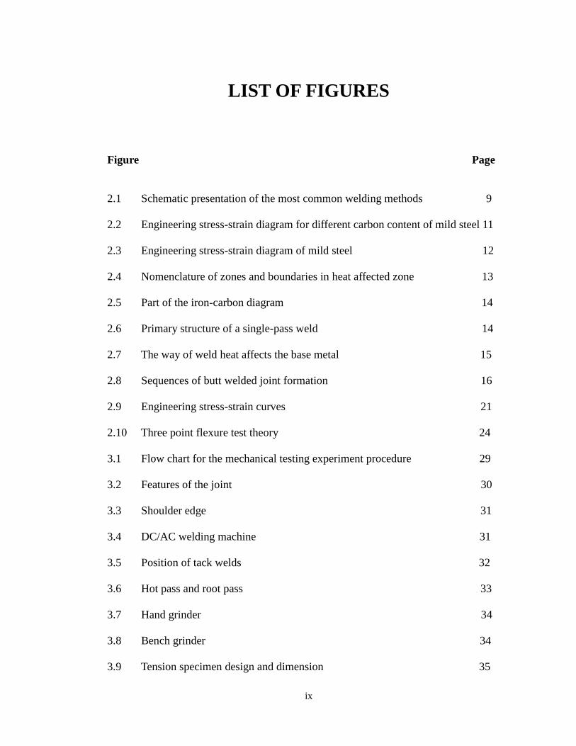
LIST OF FIGURES
Figure Page
2.1 Schematic presentation of the most common welding methods 9
2.2 Engineering stress-strain diagram for different carbon content of mild steel 11
2.3 Engineering stress-strain diagram of mild steel 12
2.4 Nomenclature of zones and boundaries in heat affected zone 13
2.5 Part of the iron-carbon diagram 14
2.6 Primary structure of a single-pass weld 14
2.7 The way of weld heat affects the base metal 15
2.8 Sequences of butt welded joint formation 16
2.9 Engineering stress-strain curves 21
2.10 Three point flexure test theory 24
3.1 Flow chart for the mechanical testing experiment procedure 29
3.2 Features of the joint 30
3.3 Shoulder edge 31
3.4 DC/AC welding machine 31
3.5 Position of tack welds 32
3.6 Hot pass and root pass 33
3.7 Hand grinder 34
3.8 Bench grinder 34
3.9 Tension specimen design and dimension 35

x
3.10 Transverse face bend specimens 36
3.11 Dimension and design of transverse face bend specimen 37
3.12 Transverse root bend specimens 37
3.13 Dimension and design of transverse root bend specimen 38
3.14 SHIMADZU Autograph testing machine 39
3.15 Equipment setup for three point flexure test 42
4.1 Stress-strain Curve for Specimen 4 48
4.2 Chart for tension stress results of welded and base metal specimens 48
4.3 The welded specimen after tension test 50
4.4 The base metal specimens after tension test 51
4.5 Chart for flexure stress results 53
4.6 Chart for Young’s modulus results of transverse face bend 54
4.7 Chart for flexure stroke before fracture results 54
4.8 Chart for flexure stress results of transverse root bend 56
4.9 Chart for Young’s modulus results of transverse root bend 58
4.10 Chart for flexure stroke before fracture results 58
4.11 The shape of face and root bend specimens 59
4.12 Failure of the tension welded specimen 60
4.13 Failure of the face and root bend specimens 60

xi
LIST OF ABBREVIATIONS
E - Young’s Modulus
F - Load to failure
W - Weight
ε - Strain
σ - Tensile Strength
HAZ - Heat Affected Zone
L - Support span
m - Slope
mm - Millimeter
MPa - Mega Pascal

1
CHAPTER 1
INTRODUCTION
1.1 Background of Welding
Welding is the two pieces of metal which is fastened together to produce a
coalescence of material by heating them with a high temperature to cause softening
or melting during the process. It is a joining process that produces fusion of metal
that requires the application of pressure or the filler metal but sometime does not
depend on both of them. For welding with the use of pressure, the separate pieces of
materials are forced to be combined to form one piece. While the welding that
requires filler metal for joining process, the filler material is added to form a
complete weld in the joint. The melting point of any filler metal used is either nearly
same as the metals being joined or below these metals not above a minimum heating
temperature. Nowadays, various types of energy sources are used for welding such as
electric arc, gas flame, ultrasound, an electron beam and others (Larry, 2004).
In the past few years, new applications, methods and systems have been
developed immensely as the contribution of welding. Moreover, the civilization of
human beings is also developed tremendously and the industries have grown rapidly
as well. The continuing research causes welding become a premier leader in
industrial processes. Meanwhile, the prevailing of welding also possible to develop
new industries like space industries and the nuclear power industries as well as

2
increasing the world’s supply of good if the industrial processes are simplified and
progressed rapidly (R.Bohnart, 2005).
Welding is always the preferable method to fasten the metal and can be applied
in many different environments like in the open air, under water and even in outer
space. This is because it is the strongest and most common method of permanently
joining steel components together. However, the suitable type of welding process
should be chosen from the many types of prevailing welding processes so that the
product can be fabricated with a high quality, long lasting, attractive and safe. In the
present day, there are over 90 welding process used in all industries. The uses of the
welding in industries have been expanded and redesigned to meet the current special
needs in various industries.
As the civilization developed, the improvement of many tools, materials and
machinery has resulted in development of welding technology. As industry expands
and improves its technology, new modern welding techniques will advance quickly
and play a vital part in progress (R.Bohnart, 2005).
At the present time, there are five welding associations that provide standards
and guidance related to the welding industry as shown below (R.Bohnart, 2005):
1) American National standards Institute (ANSI)
2) American Petroleum Institute (API)
3) American Society of Mechanical Engineers (ASME)
4) American Welding Society (AWS)
5) American Bureau of Shipping (ABS)
3
1.2 Problem Statement
Nowadays, steel pipe plays a vital role and is widely used in various industries
as it has numerous functions in structure, piping system and others. There are many
methods for joining the pipes such as threaded joints, flanges with bolts and gaskets,
welded joints, lead and hemp joints and other types of joints. Hence, it is essential for
design engineers and material engineers to select the most suitable way to join the
pipe together in any kinds of application so that the joint is adequate and economical.
However, it becomes a major problem for selecting the most suitable joint
among of these joints when joining of steel pipes. Design and material engineers
need to investigate the mechanical behavior of any types of joint to suit the pipe
joining so that the design requirement can be achieved especially for the structural
design. Failure in selection of appropriate pipe joint for design will result in loss of
material, money, time or even life.
Therefore, in this project, the mechanical behavior of the pipes after being
welded and the strength of the welded pipe is determined whether or not it is same as
its base metal pipe or even better than it. Besides that, the welded joint is also
identified whether it is stronger than the parent metal pipe or vice versa.

4
1.3 Objectives of the Final Year Project
In this project, there are several objectives on studying mechanical testing on
welded pipes. Two main objectives that are needed to be achieved at the end of this
study are:
To study the strength of the welded pipe by using mechanical testing based
on ASME codes
To study the testing of welds to investigate and identify that the welded joint
strength equals or even better than the design base metal pipe strength
.
1.4 Project Strategy
In this project, the understanding of the welding and fabrication procedure,
welded piping system and mechanical testing is important. The analysis of the
various mechanical testing will help to test the welded pipes to achieve the
qualification. The study conducted will be a great help in testing the welded pipes to
meet the requirement of piping system in various industries. Testing concept is
generated base on the analysis, research and study done on the literature review. The
project carried out on is expected to bring benefit and deliverable to the UNIMAS.

5
CHAPTER 2
LITERATURE REVIEW
2.1 Introduction
The literature review will describe about the welding and mechanical testing on
the welded pipes and the weld. This chapter will analyze of the mechanical testing
and the purposes of them on the welded specimens. Furthermore, this chapter also
includes the discussion on the pipe welding as well as the description of weld.
2.2 Analysis of Mechanical Testing
Mechanical testing or destructive test is where an assessment of the material
strength that apply to a controlled stress. Its main function is to evaluate mechanical
properties of materials and measurement of the material’s ability to carry or resist
mechanical forces such as tension, shear, compression, torsion and impact.
Specification is needed to some form of mechanical test as a matter of course with
high quality components or where any failure in the design load applied would bring
problem that can cause any injuries and increase the costs (Ross, 1995). A
mechanical testing is normally considered as a destructive examination process as the
testing usually results in damage permanently to the testing specimen. A part or

6
sometime whole sample specimen is consumed, broken, or damaged to the degree
that it is no longer can be used for its other intended purpose (O.Fellers, 1990).
In mechanical testing, the mechanical properties of material under different
applied loads and the behavior and structural response of a specimen can be analyzed
and investigated in spite of testing the failure of the specimen. The test can be either
static or dynamic at where the stress is applied slowly during static test while for
during the dynamic test, the stress is suddenly applied.
The mechanical testing is much easier to be conducted, more information and
data can be obtained and convenient for the interpretation compared with the non-
destructive testing. Mechanical testing is widely used for welder and procedure
qualification because the methods used in various kind of testing are highly reliable
and relatively inexpensive. In the mechanical testing, only a small number of
specimens are destroyed and the cost of it can be considered negligible. Therefore,
many material testing experiments prefer mechanical testing as it is most suitable,
economic for the objects which will be mass produced. In the case of a building,
mechanical testing is not preferable as only one or few items are to be produced and
mostly not economical.
Various code-making bodies such as the American Society of Mechanical
Engineers (ASME) have developed and provided certain general test procedure and
standard for the industry as a guideline and instruction for any testing. The only
differences are the tests may be differ in application and detail from industry to
another industry, the basic procedures and types of the test specimens which are
recommended by the various code-making bodies are still continuously applied in
their material testing.
7
2.2.1 Overview of Mechanical Testing on Welded Pipes
Mechanical testing plays a vital aspect of weldability study. In the design work,
mechanical testing is essential to be used to test the welded pipe so that the engineers
can determine and do the research on the mechanical properties of welded joint
before using it. Mechanical testing is conducted to determine the quality of the weld
and the skill of the welder after a weld has been completed so that the quality
assurance and quality control of the welded pipes can be ensured. Fracture, failure
and engineering design analysis of the welded pipes can be investigated and
interpreted by mechanical testing. Furthermore, mechanical testing is able to reveal
the important weld behaviors such as weld button size as well as obtaining
quantitative measures of a weld’s strength (O.Fellers, 1990).
The main function of the mechanical test is to determine a quantitative measure
instead of qualitative sense of weld quality. Mechanical testing of a weldment can be
static or dynamic as a weld’s strength commonly refers to its capability to withstand
both static and dynamic loads. The dynamic strength of spot welds is an important
quality index because of its implication on the performance of welded structures
while the static tests are normally conducted to determine the weldability of metal.
There are two types of static tests which are tension test and shear test while the
dynamic tests are generally refer to fatigue and impact test. Static tests are preferable
to be conducted to test the weldment as the dynamic testing is relatively low in
reliability and repeatability as well as cost expensive high cost.

8
2.3 The Functions of Welding in Industry
Welding is a technological process that is widely practiced in modern
engineering and industries nowadays. It is a very economical process and used in
both manufacturing and repairing work. Many industries select welding in some
particular jobs as preferable joining method because there are numerous great
advantages from welding. For instance, industries such as oil and gas, automotive,
military, industrial construction and others are more preferred welding as joining
method. Generally, welding plays two important roles in industries such as a means
of fabrication and a technique for maintenance and repair. (J.Sacks, 1984).
Welding fabrication is very useful as it can provide more flexible design and
the design cost is saved because the patterns such as the pattern drawing, pattern
making and repairing are not required in welded design. Some industries use welding
method to replace riveting method in the purpose of saving weight. Welding
fabrication can minimize the inventory and obsolescence charges as well as the
worker-hours of production (J.Sacks, 1984).
Welding is also used for maintaining and repairing the broken parts
immediately by welding and the cost interruptions in production and expensive
replacement can be minimized. With the use of welding, some particular production
requirements can be achieved by innovating the production equipment, shop fixtures
and many types of structures to fulfil the requirement (J.Sacks, 1984). Figure 2.1
shows the schematic presentation of the most common welding methods (Weman,
2003).

9
Figure 2.1: Schematic presentation of the most common welding methods (Weman, 2003)
Welding
Pressure welding Fusion welding
Resistance welding
Spot welding
Seam welding
Flash welding
Butt welding
Projection
welding
Friction
welding
Ultrasonic
welding
Induction
welding
Cold pressure
welding
Gas welding Arc welding Power beam welding
Metal arc welding Gas shielded arc
welding
Laser welding Electron beam
welding
Manual metal
arc welding
MMA
Submerged arc
welding SAW
Gas tungsten
arc welding TIG
Gas metal arc
welding
MIG/MAG
Plasma welding