mechanical services design brief
TRANSCRIPT

(UNCONTROLLED WHEN PRINTED)
TECHNICAL STANDARD
MAS-MECH-001 MECHANICAL SERVICES DESIGN BRIEF

(UNCONTROLLED WHEN PRINTED) MAS-MCH-001
VERSION: 1 TECHNICAL STANDARD
24/10/2017 MECHANICAL SERVICES DESIGN BRIEF 2 of 88
DISCLAIMER
This Standard has been developed by Australia Pacific Airports (Melbourne) Pty Ltd (Melbourne
Airport) for use in the construction and maintenance of works at Melbourne Airport in order to:
Provide guidance to persons planning and performing those works as to airport specific
requirements; and
Promote consistency in utilities infrastructure across the airport generally.
While Melbourne Airport expects users to comply with this Standard, users should keep in mind that in
some circumstances a higher standard than the minimum set out in this Standard may be warranted.
In particular, users are also required to:
Exercise their professional judgement as to whether this Standard is appropriate to the particular
circumstances;
Bring to the task their knowledge of other relevant industry standards and practices that should
also apply; and
Request from Melbourne Airport, authority to depart from this Standard, and advise why such
departure is appropriate.
The use of the information contained in this Standard is at the user’s sole risk. Melbourne Airport,
officers, employees and agents:
Make no representations, express or implied, as to the accuracy of the information contained in
this Standard;
Accept no liability for any use of the information contained in this Standard or reliance placed on
it; and
Make no representations, either express or implied, as to the suitability of the information
contained in this Standard for any particular purpose.
Melbourne Airport does not endorse, or in any respect warrant, any third party products or services by
virtue of any information, material or content referred to, included in, or linked to from this Standard.
Please note that this Standard may be updated from time to time without notice and shall be subject
to Periodic Review as part of the Melbourne Airport Document Control Process (MAS-GEN-002).
Users are required to check they are referring to the most recent version.
Copyright in this document belongs to Melbourne Airport.
Version Prepared by Authorised by Publish Date
1.0 - DRAFT Jack Wardale (AECOM) Jeff Mansfield (APAM) 25/08/2017
2.0 - FINAL Jack Wardale (AECOM) Jeff Mansfield (APAM) 24/10/2017

(UNCONTROLLED WHEN PRINTED) MAS-MCH-001
VERSION: 1 TECHNICAL STANDARD
24/10/2017 MECHANICAL SERVICES DESIGN BRIEF 3 of 88
CONTENTS
1 Overview ....................................................................................................................................... 5
2 Scope ............................................................................................................................................ 6
2.1 Mandatory and Non-Mandatory Requirements .................................................................. 6
2.2 Limits of Standard ............................................................................................................... 6
2.3 Deviation from Standard ..................................................................................................... 6
3 Reference Documents .................................................................................................................. 7
3.1 Statutory Requirements ...................................................................................................... 7
3.2 Australian Standards .......................................................................................................... 7
3.3 Melbourne Airport Standards .............................................................................................. 9
3.4 Melbourne Airport Drawings ............................................................................................... 9
3.5 Rules, Codes of Practice and Guidelines ......................................................................... 10
3.6 Selection and Interpretation of Standards ........................................................................ 10
4 Definitions ................................................................................................................................... 11
4.1 Abbreviations .................................................................................................................... 11
5 General Requirements ................................................................................................................ 12
5.1 Sustainability ..................................................................................................................... 12
5.2 Safety in Design................................................................................................................ 12
5.3 Fitness for Purpose .......................................................................................................... 12
5.4 Life Cycle Costing ............................................................................................................. 12
5.5 Maintainability ................................................................................................................... 13
5.6 Testing and Commissioning ............................................................................................. 13
5.7 Durability ........................................................................................................................... 14
5.8 Asset Management ........................................................................................................... 14
5.9 Building Information Modelling ......................................................................................... 14
5.10 APAM Accredited Suppliers & Specialists ........................................................................ 15
6 Operational Philosophy ............................................................................................................... 16
6.1 Mechanical Services Overview ......................................................................................... 16
6.2 Distribution Network ......................................................................................................... 16
7 Mechanical Services Design Criteria .......................................................................................... 17
7.1 Internal & External Design Conditions .............................................................................. 17
7.2 Mechanical HVAC Internal Design ................................................................................... 18
7.3 Design Occupancy and Ventilation Rates ........................................................................ 19
7.4 Mechanical Services General Design Criteria .................................................................. 20
8 Thermal Plant .............................................................................................................................. 23
8.1 Water Chillers ................................................................................................................... 23
8.2 Cooling Towers – Induced Draught .................................................................................. 24
8.3 Central Heating Plant ....................................................................................................... 26
9 Air Conditioning Equipment ........................................................................................................ 27
9.1 Air Handling Units ............................................................................................................. 27
9.2 Fan Coil Units ................................................................................................................... 28

(UNCONTROLLED WHEN PRINTED) MAS-MCH-001
VERSION: 1 TECHNICAL STANDARD
24/10/2017 MECHANICAL SERVICES DESIGN BRIEF 4 of 88
9.3 Packaged Air Conditioning Units ...................................................................................... 29
9.4 Variable Refrigerant Volume (VRV) Systems ................................................................... 29
10 Mechanical Equipment................................................................................................................ 33
10.1 Pumps ............................................................................................................................... 33
10.2 Fans .................................................................................................................................. 34
10.3 Heat Exchangers .............................................................................................................. 36
10.4 Expansion Tanks .............................................................................................................. 38
11 Ductwork and Associated Equipment ......................................................................................... 40
11.1 Attenuators ....................................................................................................................... 41
11.2 Dampers, Diffuser’s, Grilles and Registers ...................................................................... 42
11.3 Air Filters ........................................................................................................................... 47
11.4 Space Heating Equipment ................................................................................................ 49
12 Pipework and Associated Equipment ......................................................................................... 51
12.1 Pipework Design Criteria .................................................................................................. 51
12.2 Pipework - General ........................................................................................................... 51
12.3 Valve Provisions ............................................................................................................... 52
13 Control Valves ............................................................................................................................. 55
13.1 Automatic Flow Control Valves ......................................................................................... 55
13.2 Differential Pressure Control Valves................................................................................. 56
13.3 Pressure Independent Control Valves .............................................................................. 56
13.4 Control Valve Arrangements for AHU’s & FCU’s ............................................................. 57
13.5 High Temperature Heating Hot Water Control Valves ..................................................... 59
14 Thermal Energy Metering Requirements .................................................................................... 60
15 Mechanical Electrical Installations .............................................................................................. 61
15.1 Mechanical Services Switchboards .................................................................................. 62
15.2 Variable Speed Drives ...................................................................................................... 63
15.3 Harmonic Distortion .......................................................................................................... 63
16 Labelling and Identification ......................................................................................................... 64
17 Noise & Vibration Control Requirements .................................................................................... 65
18 Water Treatment Requirements ................................................................................................. 66
18.1 Design & Installation Requirements ................................................................................. 66
18.2 Closed Systems ................................................................................................................ 67
19 Automatic Controls and Building Management System Requirements ...................................... 70
19.1 Typical Controls Schematics (SLD’s) ............................................................................... 70
20 Access Requirements ................................................................................................................. 78
21 Operation of Mechanical Services under Fire Alarm .................................................................. 81
22 Testing, Balancing & Commissioning Requirements .................................................................. 82
22.1 Allocation of Commissioning Responsibilities .................................................................. 82
22.2 Production of Handover Information ................................................................................. 85

(UNCONTROLLED WHEN PRINTED) MAS-MCH-001
VERSION: 1 TECHNICAL STANDARD
24/10/2017 MECHANICAL SERVICES DESIGN BRIEF 5 of 88
1 Overview
This design brief gives detail regarding the operating and performance characteristics for mechanical
services at Melbourne Airport.
This Standard shall be used by consultants, designers and contractors for new projects for the design
of mechanical services system and equipment.
This documented is intended to be a design brief for the operational philosophy and design
specifications for the mechanical services at Melbourne Airport.

(UNCONTROLLED WHEN PRINTED) MAS-MCH-001
VERSION: 1 TECHNICAL STANDARD
24/10/2017 MECHANICAL SERVICES DESIGN BRIEF 6 of 88
2 Scope
2.1 Mandatory and Non-Mandatory Requirements
The following language key describes the requirements of imperative statements within this Standard.
The word:
Shall - describes mandatory requirements;
Should - describes non-mandatory best practice recommendations; and
May - describes possible options that are not mandatory or best practice.
2.2 Limits of Standard
Users of this Standard shall explicitly demonstrate compliance with this Standard. Compliance shall
be demonstrated through:
Adopting appropriate standards and providing explicit reasons for their selection; or
Providing an explicit, evidence based, business case supporting compliance with this standard.
The general statement “in accordance with Melbourne Airport Standards”, shall not be deemed
acceptable without further detail.
Questions regarding this Standard shall be addressed to the Standards group via
The contractor shall be responsible for ensuring mechanical services installations comply with all
relevant standards and government regulations.
2.3 Deviation from Standard
Where the requirements of this Standard are not able to be met through the design process, a request
for deviation shall be made. Requests for deviation shall explicitly state the areas where a proposal
does not comply. As a minimum, submissions shall include detailed commentary on:
The reason for deviation from this Standard;
How the deviation complies with all other mandatory standards or regulations; and
Any impacts on safety, reliability, ongoing cost, operability and maintenance.
Deviations from any part of this Standard shall be submitted to the Melbourne Airport Standards Team
for approval before they are implemented or incorporated into a design. Approval of a deviation from
this Standard is not guaranteed. Approval of a deviation shall not constitute approval of the same
approach in the future.
(UNCONTROLLED WHEN PRINTED) MAS-MCH-001
VERSION: 1 TECHNICAL STANDARD
24/10/2017 MECHANICAL SERVICES DESIGN BRIEF 7 of 88
3 Reference Documents
The following normative documents contain requirements which, through reference in this text,
constitute requirements of this standard. For dated references, subsequent amendments or revisions
shall not apply. For undated references, the latest edition of the normative document referred to
applies.
3.1 Statutory Requirements
All woks shall be in accordance with the requirements of any Authority having jurisdiction over them
and Melbourne Airport Standards.
Typical national and local Statutory Authorities include:
Building Code of Australia (National Construction Code) and Building Permit conditions;
Australian Communications Authority (ACA);
All applicable Australian Standards;
WorkCover requirements;
OHS Regulations;
Electricity Supply Authorities;
Fire Brigade requirements; and
All Local Council regulations.
Consent should be sought from the Melbourne Airport Project Sponsor, where project personnel
(designer, contractor, etc.) wish to utilise equivalent ISO standards to Australian Standards stated in
these design standards.
3.2 Australian Standards
AS 1023.3 Inherent overheat protectors
AS 1217 Acoustics – Determination of sound power level of noise sources
AS 1217.3 Acoustics - determination of sound power levels of noise sources -
precision methods for discrete - frequency and narrow band sources in
reverberation rooms
AS 1324.1 Air filters for use in general ventilation and air conditioning -
application, performance and construction.
AS 1324.2 Air filters for use in general ventilation and air conditioning - methods
of test
AS/NZS 1530.3 Simultaneous determination of ignitability, flame propagation, heat
release and smoke release
AS 1571 Copper-seamless tubes
AS 1650 Hot-dipped galvanized coatings on ferrous articles
AS/NZS 1668.1 Fire and smoke control in multi-compartment buildings
AS 1668.2 Mechanical ventilation for acceptable indoor air quality

(UNCONTROLLED WHEN PRINTED) MAS-MCH-001
VERSION: 1 TECHNICAL STANDARD
24/10/2017 MECHANICAL SERVICES DESIGN BRIEF 8 of 88
AS/NZS 1677.1 Refrigerating systems – Refrigerant classification
AS/NZS 1677.2 Refrigerating systems – safety requirements for fixed applications
AS 1807.7 Determination of integrity of HEPA filter installations not terminally
mounted
AS 1807.9 Particle counting in clean rooms by microscopic sizing and counting
AS 1861.2 Refrigerated package air conditioners
AS 2729 Rolling bearings - Dynamic load ratings and rating life
AS 2738.2 Copper and copper alloys
AS 2784 Endless wedge belt and V-belt drives
AS 2848.1 Aluminium and aluminium alloys
AS 3100 Approval and test specification – general requirements for electrical
equipment
AS/NZS 3179 Approval and test specification – Refrigerated room air conditioners.
AS 3350.2.40 Approval and test specification – safety of household and similar
electrical appliances – electrical heat pumps, air conditioning and
dehumidifiers
AS 3666 Air handling and water systems for buildings – microbial control
AS 3709 Vibration and shock – balance quality of rotating rigid bodies
AS/NZS 3823.1.1 Performance of household electrical appliances
AS/NZS 3823.2 Performance of household electrical appliances, room air conditioners
– energy labelling requirements
AS 4254 Ductwork for air handling systems in buildings
AS 4260 High efficiency particulate air (HEPA) filters – classification,
construction and performance
AS 4429 Methods of test and rating requirements for smoke spill fans
ARI 320 Water source heat pumps
ARI 440 Room fan-coil and unit ventilators
ASHRAE 23 Methods of testing for rating positive displacement refrigerant
compressors and condensing units
ASHRAE 52.2 Method of testing general ventilation air-cleaning devices for removal
efficiency by particle size
ANSI/ASHRAE 79 Methods of testing for rating room fan-coil air conditioners

(UNCONTROLLED WHEN PRINTED) MAS-MCH-001
VERSION: 1 TECHNICAL STANDARD
24/10/2017 MECHANICAL SERVICES DESIGN BRIEF 9 of 88
ASHRAE 127 Method of rating computer and data processing room unitary air
conditioners
ASTM C534 Standard specification for preformed flexible elastomeric cellular
thermal insulation in sheet and tubular form
NCC Section J Energy Efficiency Capability
NZS 3501 Copper Tubes for water, gas and sanitation
SAA HB40 The Australian refrigeration code of good practice - for fluorocarbon
emissions
3.3 Melbourne Airport Standards
All works shall be in accordance with the requirements of key Engineering Standards below;
MAS-ELC-001 Low Voltage Systems
MAS-ELC-002 High Voltage Systems
MAS-ELC-003 Low Voltage Switchboard Design
MAS-ELC-004 High Voltage Safety and Operational Procedures
MAS-ELC-005 Aeronautical Ground Lighting
MAS-FPR-001 Fire Protection, Public Address, EWIS and Hearing Loops
MAS-GEN-004 Maintainability
MAS-GEN-005 Computer Aided Design
MAS-GEN-006 Asset Identification
MAS-GEN-007 Geographical Information System
MAS-GEN-008 Building Information Modelling
MAS-MCH-001 Mechanical Services
MAS-MCH-007 Automated Controls and Building Management System
MAS-ITC-001 APC Comms room equipment layout and commissioning standard
MAS-ITC-002 CCTV Design Standard
MAS-ITC-003 Airport Comms Distributor Spatial Requirements
MAS-ITC-004 Communications Rooms & Spaces - Standard
MAS-ITC-005 Radio Communications Installation Standards
MAS-ITC-006 Structured Cabling Standard

(UNCONTROLLED WHEN PRINTED) MAS-MCH-001
VERSION: 1 TECHNICAL STANDARD
24/10/2017 MECHANICAL SERVICES DESIGN BRIEF 10 of 88
MAS-ITC-007 Access Control
3.4 Melbourne Airport Drawings
Master Electrical & Mechanical drawings are controlled by APAM which include site-wide schematic
drawings and zone layouts. For tender documentation the engineer is to ensure any proposed
changes are marked up for APAM CAD team to update.
On completion of the project the head contractor is to ensure as-built changes are marked up for
APAM CAD team to update.
3.5 Rules, Codes of Practice and Guidelines
AIRAH Application Manuals
DA01 Centrifugal Pumps
DA02 Noise Control
DA03 Ductwork for Air conditioning
DA13 Fans
DA15 Air Filters
DA16 Air Conditioning Water Piping
DA17 Cooling Towers
DA18 Water Treatment
DA26 Indoor Air Quality
DA28 Building Management and Control Systems
Commissioning
CIBSE Commissioning Code A – Air Distribution Systems
CIBSE Commissioning Code C – Automatic Controls
CIBSE Commissioning Code M – Commissioning Management
CIBSE Commissioning Code R – Refrigeration Systems
CIBSE Commissioning Code W – Water Distribution Systems
Or
ASHRAE Guideline 0 – The Commissioning Process
ASHRAE Guideline 1.1 – HVAC&R Technical Requirements for Commissioning
3.6 Selection and Interpretation of Standards
All mechanical works shall be carried out in compliance with appropriate legislation and standards
and APAM requirements. The order of precedence shall be as follows:
Legislation,
Standards required by legislation,
APAM standards,
Consultants shall accept responsibility for the selection and use of relevant Australian, International
and APAM standards. Although a number of standards and drawings are specified in this document
they are not definitive and it is the responsibility of Consultants to fully acquaint themselves with the
various standards and select those that are relevant in meeting specific APAM project requirements.

(UNCONTROLLED WHEN PRINTED) MAS-MCH-001
VERSION: 1 TECHNICAL STANDARD
24/10/2017 MECHANICAL SERVICES DESIGN BRIEF 11 of 88
4 Definitions
4.1 Abbreviations
Abbreviation Definition
AHU Air Handling Unit
BMS Building Management System
CFC Chlorofluorocarbon
CHW Chilled Water
CRAC Computer Room Air Conditioning Unit
CU Condensing Unit
dB Dry Bulb
DDC Direct Digital Control
DN Diameter Nominal
DOL Direct On Line
FCU Fan Coil Unit
HCFC Hydro chlorofluorocarbon
HTHHW High Temperature Heating Hot Water
HVAC Heating, Ventilation and Air Conditioning
LCD Liquid-Crystal Display
LTHHW Low Temperature Heating Hot Water
MCC Motor Control Centre
MSSB Mechanical Services Switchboard
NCC National Construction Code
TSB Terminal Services Building (Central plant building at Melbourne Airport)
VRV Variable Refrigerant Volume
VSD Variable Speed Drive
WB Wet Bulb
(UNCONTROLLED WHEN PRINTED) MAS-MCH-001
VERSION: 1 TECHNICAL STANDARD
24/10/2017 MECHANICAL SERVICES DESIGN BRIEF 12 of 88
5 General Requirements
5.1 Sustainability
Users of this Standard shall demonstrate that consideration for the whole of life has been undertaken
ensuring sustainability has been optimised. Whole of life includes implementation and operation
through to decommissioning and disposal.
Works in accordance with this Standard shall consider both its effect on and how it will be affected by
the following:
Economic
Social
Environmental
Security
Operation and Maintenance
The User of this Standard shall make use of historical, current and projected / forecasted information
when assessing the Sustainable Design for the whole of life.
Users shall apply the principles of harm minimisation. Wherein scientific doubt shall not be used as a
reason to avoid undertaking preventative measures.
5.2 Safety in Design
All design and construction activities shall appropriately consider and incorporate safety in design and
construction. This shall include construction work, accessibility, operational and maintenance
consideration. Refer to Work Health and Safety Act 2011 and Work Health and Safety Regulation
2011.
5.3 Fitness for Purpose
All services, equipment and devices to be installed on APAM projects shall be fit for the intended
operational purpose.
Fitness-for-purpose refers to fitness for the specifically intended purpose by APAM in the context of
their existing and ongoing operations.
The fitness-for-purpose shall incorporate the life cycle cost elements, in particular accessibility,
maintainability, operational factors to ensure ease of maintenance, minimisation of energy
consumption, economic considerations and effective utilisation of operational personnel.
5.4 Life Cycle Costing
A whole of life view shall be taken for all design decisions taken during the design of mechanical
systems. Consequently, the specification and selection of systems, products and materials shall be
considered over a product life cycle and not merely based on initial capital cost. Therefore, Life Cycle
Costing (LCC) shall consider the initial capital cost, operational costs (e.g. energy usage and cost),
and longevity and maintenance costs. This can be described as:
LCC = Cost of (initial capital + repairs + maintenance + operation + energy + disposal)
Where:

(UNCONTROLLED WHEN PRINTED) MAS-MCH-001
VERSION: 1 TECHNICAL STANDARD
24/10/2017 MECHANICAL SERVICES DESIGN BRIEF 13 of 88
Initial Capital Cost includes removal of redundant existing equipment and pipework/ductwork,
design, project management, installation/construction, testing and commissioning and handover.
Repairs include unplanned non-maintenance activities.
Maintenance includes such items as recurrent work (e.g. filter replacement), lubrication, calibration,
software upgrade or replacement. Note that some systems or equipment elements may have a
reduced life compared with the rest of the installation. These need to be replaced at appropriate times
and due allowance is required to be made in maintenance plans and procedures.
Operation relates to those activities that are required to ensure proper on-going functionality of the
installation and equipment. It is important that Designers consider this aspect fully; otherwise
additional downtime, staffing and shift work may be unnecessarily required.
Energy is total energy (usually in kWh) required to effectively operate the plant, system or installation
over their operational life.
Disposal is the activity incurred at the end of the equipment or installation life and includes
demolition, removal from site and appropriate disposal. In addition, some equipment may contain toxic
or hazardous components which may require to be disposed by specialist organisations at significant
cost.
In most instances there are competing products, services and systems available in the market and it
is expected that various options are considered and suitable recommendations and selections made
on a life cycle costing basis. Any design change shall be able to be justified in this way.
LCC is required to consider that equipment or systems may have elements incorporating different
useful lives. It is expected that comparative LCC be demonstrated as the basis for the selection of all
systems, products and materials when fitness-for-purpose has been established.
Refer to AS/NZS 4536-1999 Life Cycle Costing for guidance of what factors shall be considered in
assessing life cycle costs.
5.5 Maintainability
All mechanical services systems and equipment shall be designed to easily facilitate safe and efficient
maintenance to be carried out by competent APAM staff and Licensed Mechanical Contractors. Due
consideration shall be made regarding equipment location and clearances to ensure safe working
practises can be implemented during routine maintenance.
Ensure that all As-Built documentation and Operation & Maintenance manuals are created or updated
as part of the project works.
5.6 Testing and Commissioning
Testing and commissioning shall be carried out in accordance with appropriate APAM, ASHRAE,
CIBSE, Australian Regulations and Australian Standard guidelines as follows;
Code M: Commissioning Management
Code A: Air Distribution Systems
Code C: Automatic Controls
Code R: Refrigerating Systems
Code W: Water distribution systems

(UNCONTROLLED WHEN PRINTED) MAS-MCH-001
VERSION: 1 TECHNICAL STANDARD
24/10/2017 MECHANICAL SERVICES DESIGN BRIEF 14 of 88
5.7 Durability
The minimum design life requirements for Mechanical Services systems shall be as per CIBSE Guide
M; Appendix 13.A1:
Shell and Tube boilers 20 years
Centrifugal Chiller’s 20 years
Pipework systems steel (closed) 25 years
Ductwork (Galvanised) 40 years
5.8 Asset Management
APAM aims to maintain international best practice in Asset Management by aligning out projects and
standards with ISO55000. The APAM Design Standards for Mechanical services aims to deliver
assets that provide lowest lifecycle costs for APAM and our stakeholders. To achieve our objectives,
accurate Asset Information is crucial. The lifecycle management of our assets is governed by our
Asset Management Framework, which defines the APAM Asset Management Policy, Strategic Asset
Management Plan and the Asset Management Plan.
The Asset Management Plan (AMP) defines the minimum Asset Management System Requirements
that form part of the Contractor’s deliverable, including but not limited to:
As-built Drawings (CAD Standard)
BIM model (BIM Standard)
Asset Data Files (Data Standard)
5.9 Building Information Modelling
APAM’s approach to BIM is aligned with industry BIM standards for information production and
delivery specifically NATSPEC, ISO19650 & PAS1192. All works are to be implemented in
accordance with the following key reference documents;
BIM Implementation Plan
This overarching document provides the roadmap for implementing a repeatable BIM process
across all projects, including data integration with operations and maintenance.
BIM Technical Standard (MAF-GEN-001 TBC)
Provides guidance to internal stakeholders (Senior Leaders and Project Management) and
external stakeholders (Designers and Constructors) regarding BIM requirements for project
delivery.
Employers Information Requirements (EIR) template (MAF-GEN-XXX TBC)
Key briefing document issued to each tenderer on capital works projects articulates both the
graphical and non-graphical information requirements to allow APAM to capture and reuse data
downstream. It articulates the specific uses of BIM on capital projects, which will vary based on
size and complexity. Content from the Implementation Plan and Technical Standard will feed into
this document.
Pre-Contract BIM Execution Plan template (MAF-GEN-YYY TNC)
This is to be completed by the design/construction teams and is the tenderers response to the
EIR document, articulating how they plan to deliver BIM

(UNCONTROLLED WHEN PRINTED) MAS-MCH-001
VERSION: 1 TECHNICAL STANDARD
24/10/2017 MECHANICAL SERVICES DESIGN BRIEF 15 of 88
5.10 APAM Accredited Suppliers & Specialists
APAM aims to maintain consistency with design and operational practices. The following stakeholders
/ specialist suppliers are to be coordinated with during design development of Mechanical services
systems;
Accredited suppliers and specialist contractors are listed as “Preferred Manufacturer” within tables 8
to 13 of this standard. Any diversion from APAM preferred manufacturer list must be agreed formally
in writing with APAM prior to installation.

(UNCONTROLLED WHEN PRINTED) MAS-MCH-001
VERSION: 1 TECHNICAL STANDARD
24/10/2017 MECHANICAL SERVICES DESIGN BRIEF 16 of 88
6 Operational Philosophy
6.1 Mechanical Services Overview
Terminals 1, 2, 3 & 4 are currently served via central thermal energy plant located within three
Terminal Services Buildings (TSBs); TSB1, TSB2 and TSB3.
TSB 1 was initially constructed in 1970 as part of the original airport works. TSB2 was subsequently
built as part of the Qantas Domestic terminal Expansion Project in 1999. TSB 3 was built adjacent to
TSB 1 in 2015/2016 and houses Trigeneration plant and absorption chillers.
Terminal Services Building No 1 (TSB1) - Serves part of Terminals T1 & T4 and all of T2 and T3
which comprises of Chilled and High Temperature Heating Hot Water services
Terminal Services Building No 2 (TSB2) - Serves Qantas Domestic Terminal Stage 2 and Qantas
Domestic Concourse B which comprises of Chilled and High Temperature Heating Hot Water
services
Terminal Services Building No 3 (TSB3) - Tri-generation System which provides Chilled and
Heating Hot Water via TSB1.
6.2 Distribution Network
The chilled and heating hot water is distributed throughout the airport via underground pipework
distribution tunnels that run beneath the terminal buildings.
The tunnels run parallel to the main terminal buildings and feed each zone via field branches. See
sketch for further indication.
The CHW and HTHHW sub mains have pipework branches that feed mechanical services plantrooms
typically located on Apron level. From these plantrooms the CHW and LTHHW (via heat exchangers)
is distributed to other plantrooms and local air conditioning equipment.
(UNCONTROLLED WHEN PRINTED) MAS-MCH-001
VERSION: 1 TECHNICAL STANDARD
24/10/2017 MECHANICAL SERVICES DESIGN BRIEF 17 of 88
7 Mechanical Services Design Criteria
The recommended design criteria for the mechanical services at Melbourne Airport are provided in
the tables below:
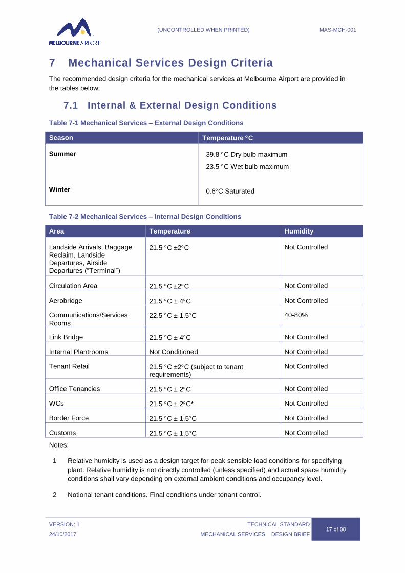
7.1 Internal & External Design Conditions
Table 7-1 Mechanical Services – External Design Conditions
Season Temperature C
Summer
Winter
39.8 C Dry bulb maximum
23.5 C Wet bulb maximum
0.6C Saturated
Table 7-2 Mechanical Services – Internal Design Conditions
Area Temperature Humidity
Landside Arrivals, Baggage Reclaim, Landside Departures, Airside Departures (“Terminal”)
21.5 C ±2C
Not Controlled
Circulation Area 21.5 C ±2C Not Controlled
Aerobridge 21.5 C ± 4C Not Controlled
Communications/Services Rooms
22.5 C ± 1.5C 40-80%
Link Bridge 21.5 C ± 4C Not Controlled
Internal Plantrooms Not Conditioned Not Controlled
Tenant Retail 21.5 C ±2C (subject to tenant requirements)
Not Controlled
Office Tenancies 21.5 C ± 2C Not Controlled
WCs 21.5 C ± 2C* Not Controlled
Border Force 21.5 C ± 1.5C Not Controlled
Customs 21.5 C ± 1.5C Not Controlled
Notes:
1 Relative humidity is used as a design target for peak sensible load conditions for specifying
plant. Relative humidity is not directly controlled (unless specified) and actual space humidity
conditions shall vary depending on external ambient conditions and occupancy level.
2 Notional tenant conditions. Final conditions under tenant control.

(UNCONTROLLED WHEN PRINTED) MAS-MCH-001
VERSION: 1 TECHNICAL STANDARD
24/10/2017 MECHANICAL SERVICES DESIGN BRIEF 18 of 88
3 Larger WCs shall be provided with conditioned supply, and exhaust –conditioned air to be
provided from adjacent concourse spaces. Single/small WCs to be provided with exhaust only.
7.2 Mechanical HVAC Internal Design
The following table details typical indoor heat loads at Melbourne Airport that shall be considered
during design of HVAC equipment:
Table 7-3 Internal Design Loads
Space
Occupants Lighting W/m²
Power W/m²
Additional Gains W/m²
Sensible W/ person
Latent W/ person
Bussing Facility 76 74 15 5 2
Fixed Link Bridge 70 60 10 5
Departures Lounge 76 74 15 5 2
Office Tenancies 70 60 9 15
Circulation Areas 76 74 15 5 2
Comms/Server Rooms - - 15 50 As per Comms unit design
WCs 76 74 5 5 -
Retail (General) 70 60 BCA 5 -
Retail (Food & Beverage)
70 60 BCA 10 -
Unallocated Area Total allowance for internal gains: 50 W/m²
Notes:
1 Baggage Handling areas are unconditioned spaces. Radiant heaters and fans should be
provided for occupant comfort.
2 Internal Plantroom loads shall be assessed on an individual basis dependant on the equipment
located within.

(UNCONTROLLED WHEN PRINTED) MAS-MCH-001
VERSION: 1 TECHNICAL STANDARD
24/10/2017 MECHANICAL SERVICES DESIGN BRIEF 19 of 88
7.3 Design Occupancy and Ventilation Rates
The following table details design occupancy and ventilation rates at Melbourne Airport that shall be
used design of HVAC equipment:
Table 7-4 Occupancy and Ventilation rates
Space Occupancy (m²/person)
Outside Air Supply Rate (L/s/person)
Design Exhaust Rate
Operation Storage/Leasing Opportunity
10 7.5 Balanced
Arrivals Bussing Lobby
1 7.5 Balanced
Future Leasing Opportunity
10 7.5 Balanced
Office & Storage 10 7.5 Balanced
Fixed Link Arrivals 1 7.5 Balanced
Fixed Departures Link Bridge
5 7.5 Balanced
Circulation 10 7.5 Balanced
Comms/Server Rooms
N/A N/A Balanced
Internal Plantrooms - N/A Balanced
Retail (General) 3.5 10 Balanced
Retail (Food & Beverage)
1.5 10 Balanced
WCs As per AS 1668.2 Nil or 90% of Exhaust rate if conditioned#
As per AS 1668.2
Notes:
Notional outside air ventilation rate to tenancies. Actual rate under tenant control. Minimum
requirements in accordance with AS 1668.2. All other areas to comply with 1668.
Final occupancy rates to be confirmed through design phases Balanced

(UNCONTROLLED WHEN PRINTED) MAS-MCH-001
VERSION: 1 TECHNICAL STANDARD
24/10/2017 MECHANICAL SERVICES DESIGN BRIEF 20 of 88
7.4 Mechanical Services General Design Criteria
Table 7-5 General Design Criteria
Item
Chilled Water Operating Temperatures (TSB1)
CHW Flow Temperature: 6C
CHW Return Temperature:14C
Chiller Condenser Water Operating Conditions
Entering Water Temperature: 29.5C
Leaving Water Temperature: 35C
High Temperature Heating Hot Water Operating Temperatures
HTHHW Flow Temperature: 165C
HTHHW Return Temperature: 140C
Low Temperature Heating Hot Water Operating Temperatures
LTHHW Flow Temperature: 80C
LTHHW Return Temperature: 60C
Pipework – Working Pressure
All pipework and piping at Melbourne Airport subject to internal pressure shall be in accordance with AS 4041
CHW: 1,600kPa
LTHW: 1,600kPa
HTHHW: 2,000kPa
Pipework Materials
CHW
Pipework ≤100diameter to be copper
Pipework ≥125diameter to be steel
Copper pipework hard drawn to AS 1432 Type B
All pipework ASTM A106 Grade B; minimum schedule 10
CCW
All CCW to be Stainless steel 316
HTHHW
Piping shall be seamless steel tube ASTM A106; or API Specification 5
LTHHW
Pipework ≤100diameter to be copper
Pipework ≥125diameter to be steel
Copper pipework hard drawn to AS 1432 Type B
All pipework ASTM A106 Grade B; minimum schedule 10
Drains
Copper
Heating Pipework – Expansion Joints
Expansion Bellows
Design of expansion bellows to be fit for purpose and in accordance with

(UNCONTROLLED WHEN PRINTED) MAS-MCH-001
VERSION: 1 TECHNICAL STANDARD
24/10/2017 MECHANICAL SERVICES DESIGN BRIEF 21 of 88
Item
AS 4041.
Pipe Jointing
Copper
≤50mm Crimp/Press Fit Veiga
>50mm Braze
Welded
LTHW/CHW Steel
≤50mm Screwed
>50mm Victaulic/Welded – (Victaulic not permitted for HTHHW installations)
Expansion Bellows To be provided by Aflex
Distribution Pipework Design Characteristics
CHW
Pressure Drop:≤300Pa/m
Min Velocity: ≥0.75m/s (600pa/m)
Max Velocity:≤2.5m/s
LTHHW / HTHHW
Pressure Drop: ≤300Pa/m
Min Velocity: ≥0.75m/s (600pa/m)
Max Velocity: ≤2.5m/s
Minimum Pipework size 20mm
Diversified Cooling and Heating Capacity (For Infrastructure assessment only)
CHW: 60% (Typical)
HTHHW: 60% (Typical)
Diversity rates to be used for future thermal plant assessments
APAM will confirm specific diversity rates to be applied for each project
Energy Meters All branches from main distribution pipework
All main branches ≥100mm
Heat exchanger – LTHHW side
All tenancy spaces both chilled and heating service
APAM to confirm requirements for each project
Filters AHU/FCU Air Flow <300L/s
Pre filter: G4 V Form Panel
Final filter: MERV 8 Pleated Panel
AHU/FCU Air Flow >300L/s
Pre filter: G3 Panel & F7 Deep bed
Final filter: activated carbon
Kitchen Exhaust: Ultra-violet filtration
Kitchen exhaust make-up air: Pre filter: G3 Panel & F7 Deep bed

(UNCONTROLLED WHEN PRINTED) MAS-MCH-001
VERSION: 1 TECHNICAL STANDARD
24/10/2017 MECHANICAL SERVICES DESIGN BRIEF 22 of 88
Item
Final filter: Activated Carbon
Redundancy Central Plant
(N+1)
Comms Rooms
(N+1) Where CHW cooling is utilised. Provide DX air conditioning units for redundancy
Pipework and Ductwork Insulation
In accordance with BCA Part J
Metal Sheathing All pipework insulation: 0.5mm zinc anneal (painted)
Vibration Isolation All plant >98%
Internal Noise Criteria (mechanical services)
Maximum Mechanical Equipment noise level: 85dBA @ 1m
Landside Arrivals, Baggage Reclaim, Landside Departures, Airside Departures: 45 NR
Circulation: 45 NR
Offices: 40 NR
Baggage Handling: <70 NR
Security Check: 45 NR
Mezzanine Plant Areas: 45 NR (External to room)
Comms/Server Rooms: 45 NR (External to room)
Internal Plantrooms: <75 NR
WCs: 45 NR
Infiltration 0.5 ACH
If space adjacent to external door – 2ACH
Pipework and Ductwork Insulation
In accordance with BCA Part J
Design Life Mechanical services shall be designed for serviceable life as per AIRAH design standards.
Mechanical Plant Efficiency
In accordance with NCC Section J
High efficiency motors minimum: IE 4 ICC Standard 6034
Seismic Restraints Provide seismic restraints to ensure compliance with AS 1170.4
Tundish Provide trapped drain Tundish to all relevant equipment

(UNCONTROLLED WHEN PRINTED) MAS-MCH-001
VERSION: 1 TECHNICAL STANDARD
24/10/2017 MECHANICAL SERVICES DESIGN BRIEF 23 of 88
8 Thermal Plant
8.1 Water Chillers
Below are the general requirements for the thermal and hydronic plant and equipment at Melbourne
Airport:
Table 8-1 Chillers
Item
General Water cooled chillers shall be in accordance with the following standards: BCA 2012 Part J requirements; AS 1210; AS 1677; AS3666; AS 4776.2
Requirements Chillers to be factory-assembled packaged fully automatic chiller sets, of proven performance for the specified capacity and operating conditions
Comprising a single centrifugal variable speed compressor, motors, flooded shell and tube evaporator(s) and condenser(s)
Full colour screen using advanced active-matrix display technology control centre and equipped with the components and accessories necessary for satisfactory operation, including but not necessarily limited to, integral piping, unit-mounted controls, electrical wiring, thermometers, LCD screen display and the like.
Compressor Single-stage centrifugal compressor shall be powered by either a direct drive hermetic, oil free, permanent magnet type, refrigerant cooled motor which are all factory pre-aligned
To maximise chiller performance, the Adaptive Control logic shall have the capability to memorise and map all friendly surge conditions thereby providing stable operation with the slowest motor speed relevant to the operating conditions.
Compressor shall be equipped with discharge and suction shutoff (isolating) valves as standard
Capacity control shall be provided by variable speed drive and inlet guide vanes, capable of reducing unit capacity to 15% of full load (at ARI 550/590 standard part load conditions). Compressor shall start unloaded and current inrush shall be limited by control to less than 105% of full load amps
Cooler Shall be flooded shell and tube type with high-efficiency enhanced copper tubes which are rolled expanded into mild steel tube plates. Tubes shall be mechanically cleanable.
Shell shall be insulated with 19mm closed-cell, foam (max K factor of 0.28) and fitted with a vapour barrier
Condenser Marine water boxes shall be factory inclusive with hinged end plates and be a 2 Pass arrangement, inclusive with a water-side drain and vent.
As part of the chiller package, an Impressed Current Condenser Protection System shall be provided with each centrifugal, including installation, commissioning and periodic maintenance.
Provide Water Boxes
Operating Unit shall be capable of starting up with 30C entering fluid temperature to the

(UNCONTROLLED WHEN PRINTED) MAS-MCH-001
VERSION: 1 TECHNICAL STANDARD
24/10/2017 MECHANICAL SERVICES DESIGN BRIEF 24 of 88
Item
Characteristics cooler and maintain continual stable operation with a minimum 10.0C entering condenser water temperature.
Condenser Water Temperature
Entering – 29.5ºC
Leaving – 35 ºC
Evaporator Water Temperature
Entering – 14ºC
Leaving – 6ºC
Preferred Refrigerant
Best available for application. Consult preferred manufacturers for guidance
Evaporator Hazard Class AS 4343
E
Evaporator Internal Inspection Required AS 3788
No
IPLV Rating Full Load: 12 (AHRI)
Cathodic Protection Impressed Current
Electrical Unit will be provided with an external main power disconnect switch located on the VSD door.
Unit shall operate on 3-phase power at the 400 ± 10% volts 50Hz.
Control voltage shall be 24 vac.
Unit shall be shipped with factory control and power wiring installed.
Power factor shall be a minimum 0.97 (compressors only) at all operating loads.
Each VSD shall be provided factory inclusive with an Active Harmonic Filter complying with IEEE Standard 51992.
Selection of HV or LV subject to review with APAM
Preferred Manufacturer
Trane, Carrier or York
8.2 Cooling Towers – Induced Draught
Table 8-2 Cooling Towers
Item
General Cooling Tower’s shall be in accordance with the following standards: AS 1657; AS 1768; AS 3666
Type Induced draft – Cross Flow –Open
Requirements Include a basin, drift eliminators, spray assembly, fans, motors and the like.
Cooling towers construction to be suitable for >six cycles of concentration
Materials Fibreglass Reinforced Polyester FRP with all interior surfaces including the fan cylinder being applied with a moulded gel coat finish to ensure ease of

(UNCONTROLLED WHEN PRINTED) MAS-MCH-001
VERSION: 1 TECHNICAL STANDARD
24/10/2017 MECHANICAL SERVICES DESIGN BRIEF 25 of 88
Item
cleaning. Provide PVC or fibreglass water connections. UV stabilise exterior surfaces.
Galvanised steel shall not be accepted.
Access Provide adequately sized removable panels or access doors to allow full and open access to all internal tower components for inspection, maintenance and cleaning in accordance with AS 3666.
Hardware Provide all wetted miscellaneous hardware items manufactured from 316 stainless steel including all nuts, bolts and washers.
Water Distribution Achieve an even spread of water over the entire fill to produce optimum heat transfer by using a spray tree and PVC pressure nozzles
Nozzles All nozzles shall be non-corrosive, self-cleaning, non-logging, and easily removable
Fans Provide variable speed adjustable pitch multi blade axial flow type fans manufactured from cast aluminium, FRP or glass reinforced polypropylene.
Motors Provide totally enclosed weatherproof electric motors in accordance with the section "Electric Motors" in this specification. The fan motor shall be fully outside of the moist discharge air stream for belt driven units. The fan motor shall be located to facilitate ease of access for maintenance.
Cold Water Basin and Sump
Manufacture from Fibreglass Reinforced Polyester FRP with a minimum thickness of 6mm with all internal surfaces finished smooth for ease of cleaning. Equip sump with a flanged return water connection manufactured in Fibre Reinforced Polyester or 316 stainless steel.
Strainers Provide cold water basin strainers of sufficient area to prevent vortexing at the outlet.
Fan Deck Design to support a uniform load of 300 kg/m² plus an additional load of up to 1500 kg/m² resulting from mechanical equipment and maintenance personnel. Provide a hot dip galvanised ladder and handrail bolted to the top perimeter of the tower deck and constructed in accordance with the Australian Standard AS 1657 and AS 3666.
Design Condition 23.5ºC wb
Preferred Manufacturer
Baltimore Air Coil (BAC), Evapco

(UNCONTROLLED WHEN PRINTED) MAS-MCH-001
VERSION: 1 TECHNICAL STANDARD
24/10/2017 MECHANICAL SERVICES DESIGN BRIEF 26 of 88
8.3 Central Heating Plant
Table 8-3 Heating Hot Water Boilers
Item
General Gas-fired HTHHW Boiler’s shall be in accordance with the following standards: AS/NZS 1200; AS 1228; AS 1796; AS 5601; AS 60079
Operating Temperature’s
Flow: 165ºC
Return: 140ºC
Type High Temperature – 3 pass
Hazard Class AS 4343
B
Preferred Manufacturer
O’Brien or equal and approved

(UNCONTROLLED WHEN PRINTED) MAS-MCH-001
VERSION: 1 TECHNICAL STANDARD
24/10/2017 MECHANICAL SERVICES DESIGN BRIEF 27 of 88
9 Air Conditioning Equipment
Below are the general requirements for the mechanical Air Conditioning plant and equipment at
Melbourne Airport:
9.1 Air Handling Units
Table 9-1 Air Handling Units
Item
General AHU’s shall be in accordance with: AS 1668.1; AS 4254; ASHRAE 79 & ARI 440
Construction Rigid extruded aluminium frame;
Fully welded galvanised steel channel base Panels of Colorbond inner and
outer skin with rigid polystyrene core;
Hinged access doors with handles;
Fan motor and drive mounted on a common rigid base;
Fan assembly mounted on springs;
Flexible connection between fan and unit air outlet spigot;
Stainless steel condensate tray;
Coils are copper tube, aluminium fins and galvanized steel frame
construction;
Space with access doors between heating and cooling coils for maintenance
and cleaning;
Horizontal and vertical configurations;
Access doors for accessing filters and both side of the coils;
Weatherproofing for external applications;
Accessible internal sections to be provided with dedicated lighting with
switches mounted externally to the unit.
Arrangement of Components
Even air distribution maintained across face of all components, air speed not to vary by more than ±20% of the mean value
Drain trays shall be provided having water-sealed traps with outlets extended to the edge of the unit. Trap seals shall be equal to the maximum operating pressure within the relevant section of the unit.
Corrosion-resistant drain trays shall be incorporated to collect and fully drain away condensate, including any condensate from adjacent sections and internal pipework.
Removal of Components
Pipe connections shall be arranged to allow individual components to be removed without disturbance to other items of equipment and pipework.
Sufficient access space shall be provided on the maintenance access side of the unit to allow any individual component to be removed and replaced.
Access Doors & Panels
Removable panels shall be provided not be more than 0.5m high. A hinged lockable door shall be provided above 0.5m.
Lockable access doors or pane for each section of the air handling plant that is not readily accessible by other means shall be provided. All access openings shall be sized for man access.
Corrosion A corrosion resistant finish shall be provided with a minimum 2 coat paint finish

(UNCONTROLLED WHEN PRINTED) MAS-MCH-001
VERSION: 1 TECHNICAL STANDARD
24/10/2017 MECHANICAL SERVICES DESIGN BRIEF 28 of 88
Item
Protection to mild steel frame sections.
Cooling Coils Face Velocity of coils limited to 2.5m/s at design conditions
Heating Coils Face Velocity of coils limited to 3.5m/s at design conditions
Maximum Pressure Drop
Cooling coils: Max Water ΔP = 45kPa, Air ΔP = 100Pa
Heating coils: Max Water ΔP = 30kPa, Air ΔP = 50Pa
Direct Expansion Cooling Coils
Copper tube shall be of refrigeration quality in accordance with AS 1571
Heat Recovery Devices
Provide Air to Air or Thermal Wheel Heat Recovery units
Where airside energy recovery devices are provided, a dedicated 100% outside air bypass shall also be provided to allow central air handling equipment to operate in full economy mode
Fans and Drives EC Plug Fans preferred
Preferred Manufacturers
GJ Walker, Air Change or Trane
9.2 Fan Coil Units
Table 9-2 Fan Coil Units
Item
General FCU’s shall be in accordance with: AS 1668.1; AS 4254; ASHRAE 79 & ARI 440
Construction 1.2mm thick galvanised sheet steel panels;
25mm insulation at 32kg/m³;
U factor : 1.0W/m2/K;
Stainless steel condensate tray;
Forward curve double inlet direct drive fans;
Coils are copper tube, aluminium fins and galvanised steel frame
construction; and
Horizontal and vertical configurations.
Coils Copper tube, aluminium fin and heavy gauge steel construction
Max Water ΔP = 40kPa
Coils shall be fitted with bleed valves
Fans and Drives EC Plug Fans preferred
Drip Trays An insulated corrosion resistant drain pan shall be graded to a screwed outlet extending beyond cooling coil and chilled water or refrigeration connections.
Leak detection tape or a high level switch shall be provided to all drain pans and linked to the BMS to facilitate early identification of significant leaks and / or drain blockages.
Preferred Trane, GJ Walker or Temperzone.

(UNCONTROLLED WHEN PRINTED) MAS-MCH-001
VERSION: 1 TECHNICAL STANDARD
24/10/2017 MECHANICAL SERVICES DESIGN BRIEF 29 of 88
Item
Manufacturers
9.3 Packaged Air Conditioning Units
Table 9-3 Packaged Air Conditioning Units
Item
General PAC Units shall be in accordance with: AS 1217; AS 1530.3; AS 1571;
AS 1668.1; AS 1668.2; AS/NZS 1677.2; AS 1861.2; AS 3350.2.40;
AS/NZS 3823.1.1;
Type PAC Units shall comprise of cooling coil, fan, compressor, condenser, filter and pre-wired electrical panel with controls
Units shall be reverse cycle type
PACs shall be mounted on anti-vibration neoprene pads.
Intake and discharge ducts shall have flexible connections
Provide a trapped condensate drain to each cooling coil
Coils Direct expansion coils shall be selected for a minimum of 3°C superheat at full load.
Condenser coils shall be corrosion protected with Heresite or Melbourne Airport approved equal treatment.
Condensing coils shall be arranged so that liquid refrigerant can gravitate to the outlet header without being trapped in the coil.
Air Filters Differential pressure monitoring shall be provided across filter beds, complete with BMS connection for remote monitoring, such that filter cleanliness can be monitored and preventative maintenance flagged.
Fan Supply air fan shall be forward curved centrifugal type with adjustable speed drive complete with vibration isolation mountings.
Compressor Multiple compressors shall be fitted to units over 12kW total cooling capacity.
Dual circuits shall be required for units over 100kW total cooling capacity with solenoid / suction unloading or a minimum of 4 compressors.
Units containing 2 compressors shall have a lead / lag changeover switch. Time delays shall be included to prevent frequent stopping and starting of the compressors.
Refrigerant Refrigerant type shall be a single component, azeotropic or zeotropic mixture. Units shall use R407c or R410a or R134a refrigerant.
Preferred Manufacturer
Air Change, Trane or Temperzone
9.4 Variable Refrigerant Volume (VRV) Systems
Table 9-4 VRV Systems – General
Item

(UNCONTROLLED WHEN PRINTED) MAS-MCH-001
VERSION: 1 TECHNICAL STANDARD
24/10/2017 MECHANICAL SERVICES DESIGN BRIEF 30 of 88
Item
General VRV systems shall be air cooled, split type multi system air conditioner
Equipment shall consist of singular condensing units connections to multiple fan coils, the condensing unit shall be able to control multiple different type and capacity fan coil units to be controlled individually
Heat Recovery function is preferred
Control To incorporate the following:
On/off switching
Fan speed selector
Thermostat setting and LCD indicating temperature setting
Operational mode
Malfunction code and filter cleaning timing.
Individual controller per room
Grouped unit control shall include:
Establishment of a building zone management system
Individual controller functions except fan speed selection per zone
Enable or inhibit individual controller functions of on\off switching
Temperature setting and operational mode
Minimum 7 days, 8 time schedules, 2 on \ off per day allocated by zone
Individual room on\off switching per room.
Branch Selector Unit Each BSU capable of controlling 1-6 FCUs
Each selector unit shall have 2 solenoid valves which are opened by a signal to cool or heat from the remote controller
BMS Units to be provided with BACNET interface to allow connection to existing BMS network
Preferred Manufacturer
Daikin Industries, Mitsubishi or LG
Table 9-5 VRV systems – Outdoor Units
Item
General
Reverse cycle air cooled condensing units shall incorporate the following:
Condenser coil
Motors
Air discharge fans
Compressor
Refrigerant circuit pipework and all components including distribution
headers
Electronic expansion valve
Solenoid valves
4 way valve
Capillaries
Filters
Shut off valves
Service ports
Receivers
(UNCONTROLLED WHEN PRINTED) MAS-MCH-001
VERSION: 1 TECHNICAL STANDARD
24/10/2017 MECHANICAL SERVICES DESIGN BRIEF 31 of 88
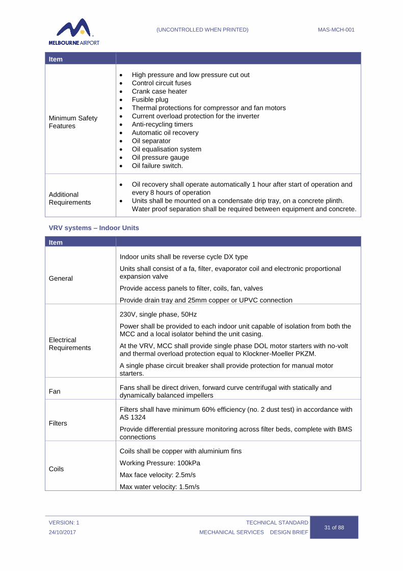
Item
Minimum Safety Features
High pressure and low pressure cut out
Control circuit fuses
Crank case heater
Fusible plug
Thermal protections for compressor and fan motors
Current overload protection for the inverter
Anti-recycling timers
Automatic oil recovery
Oil separator
Oil equalisation system
Oil pressure gauge
Oil failure switch.
Additional Requirements
Oil recovery shall operate automatically 1 hour after start of operation and
every 8 hours of operation
Units shall be mounted on a condensate drip tray, on a concrete plinth.
Water proof separation shall be required between equipment and concrete.
VRV systems – Indoor Units
Item
General
Indoor units shall be reverse cycle DX type
Units shall consist of a fa, filter, evaporator coil and electronic proportional expansion valve
Provide access panels to filter, coils, fan, valves
Provide drain tray and 25mm copper or UPVC connection
Electrical Requirements
230V, single phase, 50Hz
Power shall be provided to each indoor unit capable of isolation from both the MCC and a local isolator behind the unit casing.
At the VRV, MCC shall provide single phase DOL motor starters with no-volt and thermal overload protection equal to Klockner-Moeller PKZM.
A single phase circuit breaker shall provide protection for manual motor starters.
Fan Fans shall be direct driven, forward curve centrifugal with statically and dynamically balanced impellers
Filters
Filters shall have minimum 60% efficiency (no. 2 dust test) in accordance with AS 1324
Provide differential pressure monitoring across filter beds, complete with BMS connections
Coils
Coils shall be copper with aluminium fins
Working Pressure: 100kPa
Max face velocity: 2.5m/s
Max water velocity: 1.5m/s

(UNCONTROLLED WHEN PRINTED) MAS-MCH-001
VERSION: 1 TECHNICAL STANDARD
24/10/2017 MECHANICAL SERVICES DESIGN BRIEF 32 of 88
Item
Expansion Valve Expansion valve shall be controlled via return air temperature, refrigerant inlet and outlet temperature
Controller Requirements
On / off switching;
Fan speed selection (high, low and medium);
Thermostat setting;
Malfunction indication;
Dirty filter indication;
Automatic heating to cooling changeover mechanism; and Auto swing of
supply air for wall, cassette and under ceiling units
Provide 1 temperature sensor per room
Refrigerant Piping
Safety shall be in accordance with AS/NZS 1677.2.
Piping shall be copper in accordance with AS 1571
Copper shall be Alloy 122 in accordance with AS 2738.2

(UNCONTROLLED WHEN PRINTED) MAS-MCH-001
VERSION: 1 TECHNICAL STANDARD
24/10/2017 MECHANICAL SERVICES DESIGN BRIEF 33 of 88
10 Mechanical Equipment
10.1 Pumps
Table 10-1 Pump’s
Item
General All pumps shall be in accordance with the following standards:
AS 2417.2; AS 2345; AS / NZS 3350.2.41; AS/NZS 3350.2.51; and AS 3855.
Requirements Pump duties shall be met with the impeller shaft speed not exceeding 24rev/s (1,450RPM).
Centrifugal type preferred
Long coupled centrifugal pump
Duty and standby pumps shall have non-return valves on the discharge side and strainer’s on the suction side
Pump suction and discharge flanges shall be drilled and tapped for pressure gauge connections. Closing plugs shall be provided
Drive connections between motors and pumps shall be fully protected against accidental contact. Provision shall be made for shaft speed measurement
HTHHW pump impellers shall be constructed from stainless steel
Lifting eyes shall be fitted to components or assemblies >25kg
Pump baring’s shall be suitable for 50,000 hours working life
Bases Pumps to be sited on anti-vibration mounts
Pumps and motors shall be mounted on rigid bases, capable of preventing distortion or misalignment during operation.
Provide inertia bases
Design Requirements
Pumps shall be capable of operating from full flow to 15% of design
Pump motors shall be selected to be non-overloading when the maximum size impeller is fitted. Impellers shall be selected not to exceed 95% of the maximum impeller size that can be fitted within the casing
Minimum Pump Efficiency
Pumps shall be selected to achieve as a minimum the greater of NCC Part J requirements
Redundancy Primary pumps – N (Duty only)
Secondary pumps – N+1 (If configured in a pump bank arrangement)
CHW requirements Install all chilled water pumps in a stainless steel self-draining (to comply with AS 3666 ponding requirements) drip tray to catch all condensate formation and leakage
Drain permanently to waste by a 25mm socket in the bottom of the tray. For other pumps for condenser water, heating water and the like, provide a drain in copper pipe from the pump housing to waste.
Electrical Requirements
Provide VSDs to pumps
Preferred Manufacturer
Grundfos, Wilo and Goulds (HTHHW Service)

(UNCONTROLLED WHEN PRINTED) MAS-MCH-001
VERSION: 1 TECHNICAL STANDARD
24/10/2017 MECHANICAL SERVICES DESIGN BRIEF 34 of 88
Item
Typical Detail - Pump
10.2 Fans
Table 10-2 Fans – General
Item
General Fans shall be in accordance with all relevant standards, including the following as a minimum: AS 1668.1; AS 4429; BS 848.1; and BS 848.2
Energy Efficiency Efficiency shall be in accordance with NCC Section J
Fan Performance Fan performance shall be in accordance with AS 2936
Fan Sound Power Levels
Fan sound power levels shall be in accordance with AS 1217.3
Smoke Spill Fans Smoke spill fans shall be tested in accordance with AS 4429

(UNCONTROLLED WHEN PRINTED) MAS-MCH-001
VERSION: 1 TECHNICAL STANDARD
24/10/2017 MECHANICAL SERVICES DESIGN BRIEF 35 of 88
Item
Motors to be Class H
Electrical Requirements
Provide VSDs to Smoke Spill Fans
Preferred Manufacturers
Fantech, Aerovent or Pacific
Table 10-3 Axial Flow Fans
Item
General Axial flow fan casings shall be rigid construction of mild steel hot dip galvanised in accordance with AS 1650, or of aluminium alloy, stiffened and braced where necessary to minimise drumming and vibration.
Selection Fans shall be selected for high efficiency, low noise level, and a maximum
speed 24rev/s (1,440RPM).
Duty point shall be selected between 50% and 80% of peak pressure and the
blade pitch angle not less than 5° from the recommended maximum pitch
angle.
Fans to be sized 20% above peak flow rate
Electrical Requirements
Provide VSDs to Fans
Table 10-4 Centrifugal Fans
Item
General For fans less than 800mm diameter and of speeds below 20rev/s (1,200RPM), casing stiffeners may be the folded edges of welded side plates used to form the pedestal and scroll.
Self-aligning ball or roller type impeller bearings shall be provided. Plummer-block mounted self-aligning roller bearings shall be provided in accordance with AS 2729, with basic rating life with 10% failure, L10 of 35,000 hours with seals and grease relief or similar split bearing housings, on fans with shaft powers greater than 10kW. Bearings shall be replaceable on belt-driven fans of input shaft power 5kW and above.
Selection Fans shall be selected in accordance with the following requirements:
High efficiency, stable and quiet operation;
Supply and return air fans, having a maximum discharge velocity of 10m/s;
and
Exhaust fans having a maximum discharge velocity of 11.5m/s.
Motor power rating shall be selected in accordance with the following requirements:
For backward inclined impellers with non-overloading characteristic select
for a minimum of 15% above limit load fan shaft power at design speed
plus 10% drive losses; and
For forward curved impellers, select as for backward inclined together with
additional 20% for overloading characteristic.
(UNCONTROLLED WHEN PRINTED) MAS-MCH-001
VERSION: 1 TECHNICAL STANDARD
24/10/2017 MECHANICAL SERVICES DESIGN BRIEF 36 of 88
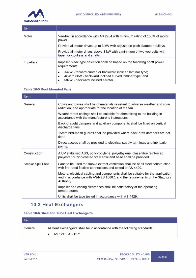
Item
Motor Vee-belt in accordance with AS 2784 with minimum rating of 150% of motor power.
Provide all motor drives up to 3 kW with adjustable pitch diameter pulleys.
Provide all motor drives above 3 kW with a minimum of two vee belts with taper lock pulleys and shafts.
Impellers Impeller blade type selection shall be based on the following shaft power
requirements:
<4kW - forward curved or backward inclined laminar type;
4kW to 8kW - backward inclined curved laminar type; and
>8kW - backward inclined aerofoil.
Table 10-5 Roof Mounted Fans
Item
General Cowls and bases shall be of materials resistant to adverse weather and solar radiation, and appropriate for the location of the fan.
Weatherproof casings shall be suitable for direct fixing to the building in accordance with the manufacturer's instructions.
Back-draught dampers and auxiliary components shall be fitted on vertical discharge fans.
15mm bird-mesh guards shall be provided where back-draft dampers are not fitted.
Direct access shall be provided to electrical supply terminals and lubrication points.
Construction A UV stabilised ABS, polypropylene, polyethylene, glass-fibre reinforced polyester or zinc-coated steel cowl and base shall be provided.
Smoke Spill Fans Fans to be used for smoke extract ventilation shall be of all steel construction with fire rated flexible connections and tested to AS 4429.
Motors, electrical cabling and components shall be suitable for the application and in accordance with AS/NZS 1668.1 and the requirements of the Statutory Authority.
Impeller and casing clearances shall be satisfactory at the operating temperatures.
Units shall be type tested in accordance with AS 4429.
10.3 Heat Exchangers
Table 10-6 Shell and Tube Heat Exchanger’s
Item
General All heat exchanger’s shall be in accordance with the following standards:
AS 1210; AS 1271

(UNCONTROLLED WHEN PRINTED) MAS-MCH-001
VERSION: 1 TECHNICAL STANDARD
24/10/2017 MECHANICAL SERVICES DESIGN BRIEF 37 of 88
Item
Requirements Heat exchangers shall be Shell and Tube type
The outer shell and tube heat exchanger shall be fabricated from carbon steel and tubes shall be fabricated copper
All shell and tube heat exchanger pipe connections shall be flanged or welded.
Design Temperatures
Primary side temperatures:
Flow - 165ºC
Return - 140ºC
Secondary side temperatures:
Flow – 80ºC
Return - 60ºC
Design Working Pressure
Shell and tubes shall be rated for the following minimum design working pressures:
Tubes: 2,000kPa (HTHW); and
Shell: 1,000kPa (LTHW).
Shell and tubes shall be rated for the following minimum design working temperatures:
Tubes: 180°C (HTHW); and
Shell: 80°C (LTHW).
BMS Monitoring
BMS monitored temperature sensors shall be provided for all flow and return lines on both high and low temperature sides of the Heat Exchanger (4 BMS temperature channels per Heat Exchanger).
Spare Capacity
Allow for 25% spare capacity on Heat Exchanger’s
Preferred Manufacturer
Shell and Tube heat exchangers shall be manufactured by Britannia Metal Industries or an equal and approved product
HTHHW valve shall be manufactured by Sauter.
Typical Detail – Shell and Tube Heat Exchanger

(UNCONTROLLED WHEN PRINTED) MAS-MCH-001
VERSION: 1 TECHNICAL STANDARD
24/10/2017 MECHANICAL SERVICES DESIGN BRIEF 38 of 88
Table 10-7 Plate Heat Exchanger’s
Item
Requirements Plate Heat Exchangers shall be fabricated from 316 stainless steel herringbone patterned corrugated plates that form channels when the heat exchanger is assembled. Individual plates shall be separated with clip-in interlocking gaskets, which are replaceable in the field.
Frame shall be sized to allow a 25% increase in Heat Exchange area to be added at a later date
End plates shall have screwed connections for piping up to 50mm in diameter and flanges for 65mm in diameter and above.
Fit condensate trays shall be drained to waste, on heat exchangers operating with fluids at a temperature lower than 15°C.
Preferred Manufacturers
Plate heat exchangers shall be manufactured by Alfa Laval or Melbourne Airport approved equal.
Typical Detail Plate Heat Exchanger
10.4 Expansion Tanks
Table 10-8 Expansion Tank’s & Auto Fill Units
Item
General Expansion tanks & Auto Fill Units shall be in accordance with the following
standards:
AS 1200; AS 3500.1.2; and AS 4343.
Diaphragm Type Pressurisation Vessels
Sealed diaphragm units shall be a complete set and include:
Feed water connection;
Make up tank;

(UNCONTROLLED WHEN PRINTED) MAS-MCH-001
VERSION: 1 TECHNICAL STANDARD
24/10/2017 MECHANICAL SERVICES DESIGN BRIEF 39 of 88
Item
Expansion vessel with replaceable internal flexible diaphragm;
System connections;
All control elements including low and high pressure cut-out switches;
Power connections and mains disconnect switch;
Run and tripped indicator lamps; and
System pressure gauges.
Capacity - Unless otherwise specified size the expansion tank to take up the
potential expansion and contraction of the fluid over the operating temperature
limits with a minimum 20% spare capacity.
Automatic Refill Units
Automatic pressurisation system refill units shall be provided to maintain closed system water pressurisation, to replace system water losses, and prevent backflow.
A single-phase centrifugal pump shall be provided, controlled by a pressure sensor, set for minimum system static pressure. The pump shall be complete with suction and discharge isolating valves, pipeline strainer, and discharge check valve. A break tank with ball float valve, cover, overflow and a removable system fill connection with backflow prevention shall be provided.

(UNCONTROLLED WHEN PRINTED) MAS-MCH-001
VERSION: 1 TECHNICAL STANDARD
24/10/2017 MECHANICAL SERVICES DESIGN BRIEF 40 of 88
11 Ductwork and Associated Equipment
Table 11-1 Ductwork - General
Item
General All Ductwork shall be designed, manufactured and installed in accordance with the following standards: AS/NZS 1668.1; AS 1668.2; AS 1682.1; AS 1682.2; and AS 4254.
Ductwork Pressure Classification
Minimum requirement for all ductwork:
Pressure Class: 500
Seal Class: C
Ductwork to be pressure tested prior to handover
Ductwork Pressure Tests
Contractor shall pressure test ductwork in accordance with AS 4254
Pressure test to be witnessed by APAM representative
Contractor to provide certificate of compliance to APAM
Table 11-2 Ductwork - Design Criteria
Ductwork System Location Max PD in Pa/M Max Velocity in m/s
Supply Ductwork C/W side wall grilles 0.8 4.5
General ventilation ductwork 0.8 6
Terminal Ductwork 0.8 2.0
Branch Ductwork 0.8 6.0
Riser Ductwork 0.8 8.0
Return Transfer ductwork 0.5 2.0
Ductwork C/W side wall grilles - 4.5
Free flow through ceiling - 3.0
Terminal Ductwork 0.8 3.0
Branch Ductwork 0.8 6.0
R/A intake to riser - 5.0
Risers 0.8 6.0
Stair Pressurisation Shaft riser 1.0 8.0
Toilet exhaust Risers 1.0 7.5
Branch Ductwork 0.8 6.0

(UNCONTROLLED WHEN PRINTED) MAS-MCH-001
VERSION: 1 TECHNICAL STANDARD
24/10/2017 MECHANICAL SERVICES DESIGN BRIEF 41 of 88
Ductwork System Location Max PD in Pa/M Max Velocity in m/s
Carpark Exhaust Risers 1.0 8.0
Ductwork C/W side wall grilles 4.5
General Exhaust Throughout 1.0 6.0
Kitchen exhaust Throughout 1.0 8.0
Smoke Exhaust / Spill
Throughout 1.0 8.0
11.1 Attenuators
Table 11-3 Attenuators
Item
General All attenuators shall comply with AS 1277
Maximum ΔP across Attenuator = 40Pa
Requirements Where airway velocity exceeds 10m/s, splitters shall be provided with
rounded nose and tapering trailing edge with a maximum angle of
divergence of 14°, to reduce the airway departure velocity to less than
5m/s.
A minimum of 1m separation shall be provided between splitter type
silencers and axial fans
Thermal insulation shall be provided to attenuators installed in thermally
insulated ducting
Circular Silencers On each of the silencer ends minimum M8 captive nuts shall be fitted to
facilitate the connection of the silencer to ductwork or fan flanges. A
minimum of 8 nuts shall be used at each end.
Silencers shall comprise a galvanized sheet metal case fabricated from not
less than 1.0mm sheet metal.
The casing joints and seams shall be either Pittsburgh or welded sheet
joints and in both cases shall be sealed with duct sealant
Rectangular Silencers
Silencers shall comprise a galvanized sheet metal case fabricated from not
less than 1.2mm sheet metal.
At each end of the silencer, proprietary HVAC ductwork flange systems, or
fabricated angle, flanges shall be fitted
The casing joints and seams shall be either Pittsburgh or welded sheet
joints and in both cases shall be sealed with duct sealant
Kitchen Exhaust All kitchen exhaust ductwork to be internally lined with Mylar
Preferred Manufacturer
Fantech, Australian Silencer Company, NAP

(UNCONTROLLED WHEN PRINTED) MAS-MCH-001
VERSION: 1 TECHNICAL STANDARD
24/10/2017 MECHANICAL SERVICES DESIGN BRIEF 42 of 88
11.2 Dampers, Diffuser’s, Grilles and Registers
Table 11-4 Dampers
Item
General Dampers shall be installed in permanently accessible positions
Balancing dampers shall be fitted in each branch from a main or sub-main duct, and elsewhere as required to satisfactorily commission the system.
Butterfly dampers with single balanced blades shall have a maximum 600mm
wide and 250mm high for rectangular or 350mm for circular.
Opposed-blade dampers to have a maximum of 230mm wide x 1,200mm long blades. Intermediate mullions shall be fitted if necessary.
Dampers shall be free of rattles, fluttering or slack movement.
Design air pressure differential shall be 1kPa
Volume Dampers Volume dampers shall be provided to permit balancing of all air outlets and branch ducts as required
Dampers shall be rigidly constructed, of the butterfly or opposed blade type, with blades securely fixed to spindles.
Nylon bearings shall be provided.
Dampers shall contain a position indicator and locking device
Automatic Control Dampers
Opposed multi-blade dampers with maximum 230mm wide and 900mm long blades having a maximum working pressure differential of 1kPa shall be provided.
Maximum leakage rate shall be 150L/s/m2 at 1.5kPa pressure differential.
Dampers shall be selected for 10m/s at maximum airflow. Modulating dampers shall not be oversized
Dampers for return air, or other air handling systems incorporating smoke spill shall be tight shut off type capable of limiting leakage to 1L/s/m2 at a pressure differential of 500kPa
Non-return Dampers Non-return (self-closing) dampers shall be constructed to ensure positive shut-off and quiet closure. Dampers shall have a maximum air resistance of 50Pa at 2.5m/s and a maximum leakage rate of 225L/s/m2 at 500Pa reverse pressure air.
Fire and Smoke Dampers
Design, install and commissioning shall be in accordance with AS 1682.1 Section 5
Fire dampers shall be installed in all ductwork passing through each and every fire compartment wall
Damper assemblies shall be of corrosion-resistant materials or be protected against corrosion.
Access panels shall be provided adjacent to fire and smoke dampers for inspection of sufficient size to permit resetting of release mechanism and blades by 1 person.
Access to fire damper and smoke damper assemblies may be provided through builders work elements.

(UNCONTROLLED WHEN PRINTED) MAS-MCH-001
VERSION: 1 TECHNICAL STANDARD
24/10/2017 MECHANICAL SERVICES DESIGN BRIEF 43 of 88
Item
Refer to the ‘Melbourne Airport Fire Safety Manual’ for further details of requirements for Fire and Smoke dampers.
Preferred Manufacturer
AirRiley, Airfoil
Table 11-5 Registers, Diffusers and Grilles
Item
General Registers, diffusers and grilles shall be in accordance with the following
standards: Air Diffusion Council ADC 1062 - GRD84; ANSI/ASHRAE 70;
and AS 1217
Registers, diffusers and grilles shall be aluminium
External finish shall be thermoset powder coated, colour as selected by the Architect unless stated otherwise.
Internal finish shall be painted matt black
Table 11-6 Types – Air Distribution – Cooling and Heating
Item
General Terminal devices shall be selected having an ADPI of 80 or better
Testing shall be in accordance with ANSI/ASHRAE 113
Cooling Requirements
Conditions shall assume 24°C room temperature and 12°C supply air temperature with:
Constant volume systems - full cooling; and
Variable volume systems - maximum airflow at minimum supply air
temperature and also minimum airflow at coincident supply air temperature
Ceiling diffusers for variable volume cooling duty with horizontal air pattern
shall be selected to avoid dumping of cold air at 45% of maximum design
airflow.
Heating Requirements
Overhead diffusers shall be selected to ensure the throw reaches to floor during heating cycle and that the supply air does not short-circuit into high level returns
Table 11-7 Types – Diffusers, Grilles & Registers
Item
Low Velocity Displacement Ventilation Diffusers
LVDV diffusers used to supply air shall be floor mounted.
LVDV diffusers shall be semi-circle with horizontal throw.
Material shall be galvanised steel. Front panel and flow equalisation element shall be perforated galvanised steel.
All exposed panels shall be resistant to damage and marking under normal operational and maintenance conditions. Surface finish shall be polyester epoxy paint.
Air Pattern shall be horizontally air throw through a full 180°.

(UNCONTROLLED WHEN PRINTED) MAS-MCH-001
VERSION: 1 TECHNICAL STANDARD
24/10/2017 MECHANICAL SERVICES DESIGN BRIEF 44 of 88
Item
Diffusers shall be complete with circular duct connection with integral gasket.
Front panel shall be detachable metallic internal structure to allow cleaning of the unit and ductwork.
An installation base shall be provided complete with kick-plate to prevent damage to the diffusers.
Where two diffusers are provided on either side of a column, a removable panel shall be provided to fill any gaps between the diffusers. This infill panel shall be of the same material and paint colour as the diffusers.
Swirl Diffusers Swirl diffusers shall be used for high level VAV systems and shall be ceiling mounted.
The diffuser shall consist of a frame with fixed internal profiled vane rings and a movable deflector ring or cylinder for throw pattern selection.
The front vane panel and movable cylinder shall be made of epoxy-painted steel and the frame of epoxy-painted aluminium. Colour of diffuser shall match the ceiling colour by the architect.
The airflow pattern shall be adjustable automatically using an electrical or wax-bulb actuator.
Circular Plaque Diffusers
Diffusers shall be circular plaque type with adjustable pattern and shall be ceiling mounted.
Baffles shall be fitted for 3-way, 2-way or 1-way pattern.
Pattern control shall be by height adjustment of plaque.
Door Relief Air Grilles
Door relief air grillers shall be horizontal chevron blades with double sided telescopic frames to suit a door thickness of 30mm to 50mm used for relief air.
Material shall be extruded aluminium.
Blade spacing shall be 25mm centres maximum and sight-proof when viewed from the same level.
Light proof grilles shall be horizontal double chevron black finished blades with double-sided telescopic frames to suit a door thickness of 30mm to 50mm.
Egg Crate Grilles Egg-crate grilles shall be ceiling or high wall mounted and shall be used for return, relief or exhaust air.
Grilled shall be of egg-crate type having 1mm thick 12mm x 12mm x 12mm deep aluminium core and extruded aluminium frame.
Fixed Blade Bar Grilles
Fixed blade bar grilles shall be side wall, sill or floor mounted and shall be used for supply and return air.
Type shall be continuous multiple slot extruded aluminium bar grilles.
Side wall or sill bars shall be 3mm wide at 12.5mm spacing.
Floor bars shall be 6mm wide at 12.5mm spacing.
Pattern control shall be by fixed longitudinal blades having a 0° or 15° deflection.
Sidewall supply diffusers shall have fitted vertical adjustable blades behind
Plenum shall be minimum 0.8mm zincanneal having a maximum length

(UNCONTROLLED WHEN PRINTED) MAS-MCH-001
VERSION: 1 TECHNICAL STANDARD
24/10/2017 MECHANICAL SERVICES DESIGN BRIEF 45 of 88
Item
1,200mm
Half Chevron Grilles Half chevron grilles shall be ceiling or wall mounted and shall be used for return or exhaust air.
Grilles shall be straight horizontal blades having 60% minimum free area
Jet Diffusers Jet diffusers shall be circular, with two or more spun aluminium flaring concentric nozzles in a cylindrical housing.
Pattern control shall be throw and spread adjustable by reversing nozzles.
Direction adjustment shall be by angling cores.
Light Air Diffusers Light air diffusers shall be in accordance with AS 2946
Diffusers shall be ceiling mounted, recessed luminaires and air diffusers - Interface requirements for physical compatibility and used for supply and return air
Air pattern shall be controlled by a J-blade
Single boots shall be oval inlet to suit ≤150mm flexible duct.
Double boots shall be oval inlet to suit >150mm flexible duct
Linear Plenum Diffusers
Linear plenum diffusers shall be ceiling mounted and shall be used for supply and return air.
Plenum diffusers shall be designed to suit ceiling 2 or 3 slot T-bar system installed by the ceiling contractor. Jointing of plenums onto T-bar diffuser shall be airtight.
Linear plenums shall be arranged with linear outlets and air pattern controls and oval duct inlets
Inactive sections shall be extended as shown. Matt black blanking plates shall be fitted where not used for return air
Linear Slot Diffusers Diffusers shall be continuous single / multiple 20mm slot extruded T-bar diffusers with pattern control blades and plenum boxes. Adjustable centre sections shall allow full adjustment of air pattern through 180°. Jointing of plenums onto diffuser shall be airtight
Inlets shall be centrally located on sides
Inactive sections shall extend as shown. Matt black blanking plates shall be fitted where not used for return air.
Louvre Faced Ceiling Diffusers
Louvre faced ceiling diffusers shall be ceiling mounted.
Diffusers shall be multi-bladed, circular, square or rectangular complete with a removable core and cushion head.
Diffusers shall be extruded aluminium
Cushion head shall be minimum 0.8mm zincanneal having an internal matt black finish.
Install baffle plates behind circular or four-way faced diffusers to provide 3-way, 2-way or 1-way blow pattern control as required. 3-way, 2-way or 1-way blow square or rectangular cores shall only be used where specified.
Discharge pattern shall be by circular diffuser - height adjustment of centre

(UNCONTROLLED WHEN PRINTED) MAS-MCH-001
VERSION: 1 TECHNICAL STANDARD
24/10/2017 MECHANICAL SERVICES DESIGN BRIEF 46 of 88
Item
cone.
Single Deflection Universal Grilles
Single deflection universal grilles shall be wall mounted and shall be used for return or exhaust air.
Diffusers shall be adjustable horizontal aerofoil blades.
Material shall be extruded aluminium blades and frame.
Blade spacing shall be 20mm maximum.
Square Plaque Diffusers
Square plaque diffusers shall be ceiling mounted.
Diffusers shall be square plaque type with adjustable pattern.
Baffles shall be fitted for 3-way, 2-way or 1-way pattern.
Pattern control shall be by height adjustment of plaque.
Universal Supply Registers
Universal supply registers shall be wall mounted.
Registers shall be double deflection with longitudinal aerofoil front blades and vertical aerofoil rear blades. All blades shall be individually adjustable. Multi-bladed stream splitter dampers shall be fitted at register take-offs. Multi-bladed opposed-blade dampers shall be fitted at the last register take-off.
Blade Construction shall be ±45° adjustment, spacing at 20mm maximum and supported at 600mm maximum centres.
Weather Louvres Weather louvres shall be wall mounted.
Weather louvres shall be provided at all air intakes and exhausts through walls complete with bird / vermin screens.
Screens shall be constructed from 1.5mm thick galvanised steel or bronze wire at 12mm centres. Fixings are to be concealed.
Ductwork plenums shall slope behind louvres towards the louvres ensuring any carryover moisture will discharge via the louvre.
Plenums shall be painted internally with either epoxy resin or bitumastic paint.
Normal duty louvres shall have:
Horizontal extruded aluminium louvre blades at 45° with anti-carryover rain
trap;
Blade pitch: 50mm to 100mm; and
Blade support: 1,200mm maximum centres.
Heavy duty louvres shall have:
Horizontal extruded aluminium two-stage louvre blades which divert air
through two 90° bends;
Blade pitch: 100mm; and
Blade support: 1,200mm maximum centres.
Air pressure drop shall be 50Pa max at 1.25m/s face velocity.
Water elimination shall be tested with 0.11L/s of water per m2 of louvre
introduced into the airstream at 16m/s with zero water penetration.
Wall Mounted Return Air Grilles
Wall grilles shall be rigidly constructed from extruded aluminium sections and shall be the fixed fin louvre type with 45° blades at not greater than 25mm

(UNCONTROLLED WHEN PRINTED) MAS-MCH-001
VERSION: 1 TECHNICAL STANDARD
24/10/2017 MECHANICAL SERVICES DESIGN BRIEF 47 of 88
Item
Preferred Manufacturers
Halton, Holyoake, Krantz
11.3 Air Filters
Table 11-8 Air Filters – General
Item
Standards Air filters shall be in accordance with the following standards:
AS 1324.1; AS 1324.2; AS/NZS 1530.3; AS/NZS 1668.1; AS 1668.2;
AS 1807.7; AS 1807.9; AS 3666 and AS 4260
General Deep bed/bag filters are preferred to panel type filters
Typically air filters are required for the following applications:
AHU with the outside air requirement;
FCU with the outside air greater than 300L/s;
FCU with the outside air less than 300L/s;
FCU with no outside air requirement;
The outside air intakes to the plantrooms; and
Make up air for different services such as kitchen exhaust
Fresh air intakes to plantrooms shall not be required to be protected with
filters
Outside air inlet separation from mechanical exhaust minimum 6m
Table 11-9 Filter Requirements for AHUs and FCUs when the outdoor air requirement > 300L/s
Item
General Activated carbon granules shall be used to remove jet fuel smells from the
air
Provide bag filters shall be provided as pre-filters before carbon filters
Where there is a risk of dust carry over from activated carbon filters,
standard bag filters shall be used before and after the carbon filter
Recommended filter configuration:
Course Panel Filter (G3 min);
Deep Bed / Bag Filter (F7 min); and
Activated Carbon Filter
Depending on the arrangement of the units served, it may be necessary to
provide activated carbon filters on return air ductwork
Preferred Manufacturers
Airepure, Camfil.
Panel Filters Requirement
Filter Performance Rating to AS 1324.1
Type G3 Rated Media
Type Airpure Australia Multi Pak
Filter size H600mm x W600mm x D600mm

(UNCONTROLLED WHEN PRINTED) MAS-MCH-001
VERSION: 1 TECHNICAL STANDARD
24/10/2017 MECHANICAL SERVICES DESIGN BRIEF 48 of 88
Maximum initial air pressure drop @ 2.5m/sec face velocity
125Pa
Nominal air flow @ 2.5 m/sec face velocity
900L/sec
Dust Holding Capacity
1,100g/m²
Deep Bed / Bag Filter s
Requirement
Filter Performance Rating to AS 1324.1
Type F7 Rated Media
Type Airpure Australia Multi Pak
Filter size H610mm x W610mm x D600mm
Maximum initial air pressure drop @ 2.5m/s face velocity
45.5Pa
Nominal air flow @ 2.5 m/s face velocity
944L/s
Dust Holding Capacity
831g @ 250Pa Resistance
Activated Carbon Filters
Requirement
Filter Size H610mm x W610mm x D600mm
Maximum initial air pressure drop @ 2.54m/s face velocity
122Pa
Nominal air flow @ 2.54m/s face velocity
944L/s
General Each activated carbon filter shall hold a minimum of 28kg activated carbon with a density of 0.48g/cm3
Table 11-10 Filter Requirements for AHUs and FCUs when the outdoor air requirement <
300L/s
Item
Feature Item
General The filter media shall be high-loft, reinforced, non-woven cotton / synthetic
blend.
V- Form filter units shall be Flanders Precisionaire Pre Pleat 40 extended
surface pleated filters or a Melbourne Airport equal approved.
To minimise pressure drop across the filters and to extend filter life 100mm

(UNCONTROLLED WHEN PRINTED) MAS-MCH-001
VERSION: 1 TECHNICAL STANDARD
24/10/2017 MECHANICAL SERVICES DESIGN BRIEF 49 of 88
nominal thickness filters should be selected with maximum velocity of 2.0m/s.
Panel V Form Pre Filter Requirements
Requirement
Filter Performance Rating to AS 1324.1
Type F6 Rated Media
Type Flanders Precisionaire Pre Pleat 40 Standard Capacity
Preferred filter size H610mm x W610mm x D100mm ( other sizes could be used)
Maximum initial air pressure drop @ 2m/sec face velocity
35Pa
Nominal air flow @ 2m/sec face velocity
720L/s
Table 11-11 Disposable Chemical and Particulate Pleated Panel Filter (Pre-Filter)
Item
Filter Performance Rating to AS 1324.1
MERV 8
Type Purafil Panel Filter
Maximum initial air pressure drop @ 2.0m/s face velocity
68Pa
Nominal air flow @ 2.0m/s face velocity
720L/s
11.4 Space Heating Equipment
Table 11-12 Space Heating – General
Item
General Space heating equipment shall be in accordance with the following standards: AS 1571 and BS EN 442
Baseboard Convectors
Copper heating elements shall be in accordance with NZS 3501 or
AS 1571 as applicable. Tubes shall be DN20
50mm x 50mm aluminium fins shall be provided located at 200fins/m
spacing. Fins shall only be fitted to top of flow pipe. Fins shall not be
provided to return pipes
Trench Heaters Copper heating elements shall be in accordance with NZS 3501 or
AS 1571 as applicable. Tubes shall be DN20
50mm x 50mm aluminium fins shall be provided located at 200fins/m
spacing. Fins shall only be fitted to top of flow pipe. Fins shall not be
provided to return pipes

(UNCONTROLLED WHEN PRINTED) MAS-MCH-001
VERSION: 1 TECHNICAL STANDARD
24/10/2017 MECHANICAL SERVICES DESIGN BRIEF 50 of 88
Item
Convectors Convectors shall be in accordance with BS EN 442-1, BS EN 442-2 and
BS EN 442-3
An angle type thermostatic radiator valve complete with isolating valve on
flow and key operated double regulating lock-shield type valve on the
return connections shall be provided
Where fitted, control dampers shall be capable of reducing the emission to
30% of maximum rated output
Natural convectors Floor-mounted finned-tube convectors shall be supported on purpose-
made pressed steel legs formed to conceal pipe connections and raise the
casing a minimum of 100mm above the floor finish
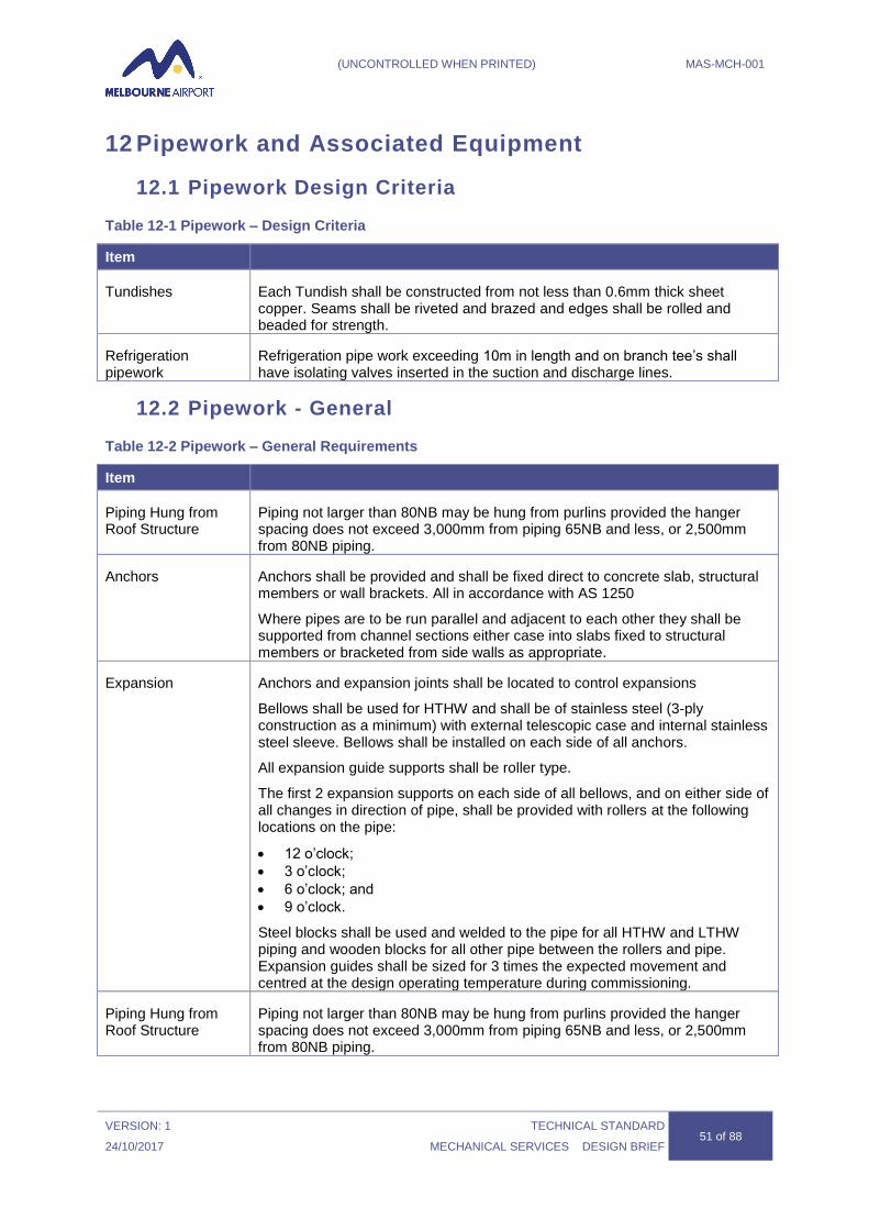
(UNCONTROLLED WHEN PRINTED) MAS-MCH-001
VERSION: 1 TECHNICAL STANDARD
24/10/2017 MECHANICAL SERVICES DESIGN BRIEF 51 of 88
12 Pipework and Associated Equipment
12.1 Pipework Design Criteria
Table 12-1 Pipework – Design Criteria
Item
Tundishes Each Tundish shall be constructed from not less than 0.6mm thick sheet copper. Seams shall be riveted and brazed and edges shall be rolled and beaded for strength.
Refrigeration pipework
Refrigeration pipe work exceeding 10m in length and on branch tee’s shall have isolating valves inserted in the suction and discharge lines.
12.2 Pipework - General
Table 12-2 Pipework – General Requirements
Item
Piping Hung from Roof Structure
Piping not larger than 80NB may be hung from purlins provided the hanger spacing does not exceed 3,000mm from piping 65NB and less, or 2,500mm from 80NB piping.
Anchors Anchors shall be provided and shall be fixed direct to concrete slab, structural members or wall brackets. All in accordance with AS 1250
Where pipes are to be run parallel and adjacent to each other they shall be supported from channel sections either case into slabs fixed to structural members or bracketed from side walls as appropriate.
Expansion Anchors and expansion joints shall be located to control expansions
Bellows shall be used for HTHW and shall be of stainless steel (3-ply construction as a minimum) with external telescopic case and internal stainless steel sleeve. Bellows shall be installed on each side of all anchors.
All expansion guide supports shall be roller type.
The first 2 expansion supports on each side of all bellows, and on either side of all changes in direction of pipe, shall be provided with rollers at the following locations on the pipe:
12 o’clock;
3 o’clock;
6 o’clock; and
9 o’clock.
Steel blocks shall be used and welded to the pipe for all HTHW and LTHW piping and wooden blocks for all other pipe between the rollers and pipe. Expansion guides shall be sized for 3 times the expected movement and centred at the design operating temperature during commissioning.
Piping Hung from Roof Structure
Piping not larger than 80NB may be hung from purlins provided the hanger spacing does not exceed 3,000mm from piping 65NB and less, or 2,500mm from 80NB piping.
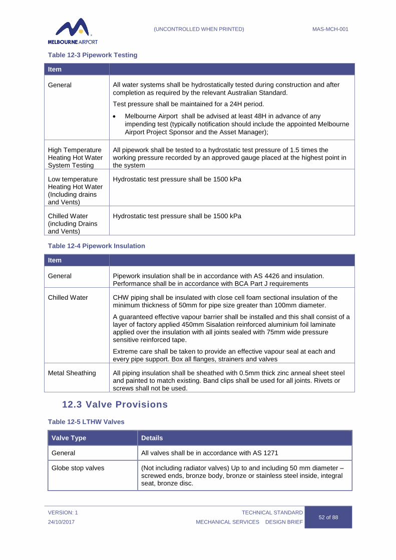
(UNCONTROLLED WHEN PRINTED) MAS-MCH-001
VERSION: 1 TECHNICAL STANDARD
24/10/2017 MECHANICAL SERVICES DESIGN BRIEF 52 of 88
Table 12-3 Pipework Testing
Item
General All water systems shall be hydrostatically tested during construction and after
completion as required by the relevant Australian Standard.
Test pressure shall be maintained for a 24H period.
Melbourne Airport shall be advised at least 48H in advance of any
impending test (typically notification should include the appointed Melbourne
Airport Project Sponsor and the Asset Manager);
High Temperature Heating Hot Water System Testing
All pipework shall be tested to a hydrostatic test pressure of 1.5 times the working pressure recorded by an approved gauge placed at the highest point in the system
Low temperature Heating Hot Water (Including drains and Vents)
Hydrostatic test pressure shall be 1500 kPa
Chilled Water (including Drains and Vents)
Hydrostatic test pressure shall be 1500 kPa
Table 12-4 Pipework Insulation
Item
General Pipework insulation shall be in accordance with AS 4426 and insulation. Performance shall be in accordance with BCA Part J requirements
Chilled Water CHW piping shall be insulated with close cell foam sectional insulation of the minimum thickness of 50mm for pipe size greater than 100mm diameter.
A guaranteed effective vapour barrier shall be installed and this shall consist of a layer of factory applied 450mm Sisalation reinforced aluminium foil laminate applied over the insulation with all joints sealed with 75mm wide pressure sensitive reinforced tape.
Extreme care shall be taken to provide an effective vapour seal at each and every pipe support. Box all flanges, strainers and valves
Metal Sheathing All piping insulation shall be sheathed with 0.5mm thick zinc anneal sheet steel and painted to match existing. Band clips shall be used for all joints. Rivets or screws shall not be used.
12.3 Valve Provisions
Table 12-5 LTHW Valves
Valve Type Details
General All valves shall be in accordance with AS 1271
Globe stop valves (Not including radiator valves) Up to and including 50 mm diameter – screwed ends, bronze body, bronze or stainless steel inside, integral seat, bronze disc.
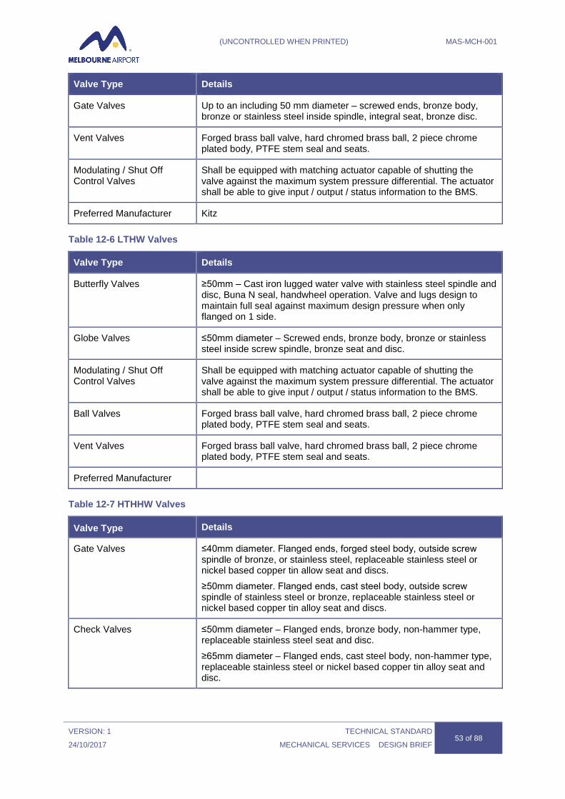
(UNCONTROLLED WHEN PRINTED) MAS-MCH-001
VERSION: 1 TECHNICAL STANDARD
24/10/2017 MECHANICAL SERVICES DESIGN BRIEF 53 of 88
Valve Type Details
Gate Valves Up to an including 50 mm diameter – screwed ends, bronze body, bronze or stainless steel inside spindle, integral seat, bronze disc.
Vent Valves Forged brass ball valve, hard chromed brass ball, 2 piece chrome plated body, PTFE stem seal and seats.
Modulating / Shut Off Control Valves
Shall be equipped with matching actuator capable of shutting the valve against the maximum system pressure differential. The actuator shall be able to give input / output / status information to the BMS.
Preferred Manufacturer Kitz
Table 12-6 LTHW Valves
Valve Type Details
Butterfly Valves ≥50mm – Cast iron lugged water valve with stainless steel spindle and disc, Buna N seal, handwheel operation. Valve and lugs design to maintain full seal against maximum design pressure when only flanged on 1 side.
Globe Valves ≤50mm diameter – Screwed ends, bronze body, bronze or stainless steel inside screw spindle, bronze seat and disc.
Modulating / Shut Off Control Valves
Shall be equipped with matching actuator capable of shutting the valve against the maximum system pressure differential. The actuator shall be able to give input / output / status information to the BMS.
Ball Valves Forged brass ball valve, hard chromed brass ball, 2 piece chrome plated body, PTFE stem seal and seats.
Vent Valves Forged brass ball valve, hard chromed brass ball, 2 piece chrome plated body, PTFE stem seal and seats.
Preferred Manufacturer
Table 12-7 HTHHW Valves
Valve Type Details
Gate Valves ≤40mm diameter. Flanged ends, forged steel body, outside screw spindle of bronze, or stainless steel, replaceable stainless steel or nickel based copper tin allow seat and discs.
≥50mm diameter. Flanged ends, cast steel body, outside screw spindle of stainless steel or bronze, replaceable stainless steel or nickel based copper tin alloy seat and discs.
Check Valves ≤50mm diameter – Flanged ends, bronze body, non-hammer type, replaceable stainless steel seat and disc.
≥65mm diameter – Flanged ends, cast steel body, non-hammer type, replaceable stainless steel or nickel based copper tin alloy seat and disc.

(UNCONTROLLED WHEN PRINTED) MAS-MCH-001
VERSION: 1 TECHNICAL STANDARD
24/10/2017 MECHANICAL SERVICES DESIGN BRIEF 54 of 88
Valve Type Details
Globe Valves ≤50mm diameter – Flanged ends, bronze body, bronze or stainless steel outside screw rising spindle, replaceable stainless steel seat and disc.
Modulating / Shut Off Control Valves
Provided with stainless steel trim and high temperature stuffing box, flanged ends. Gland packing shall be pure PTFE. Each valve shall be equipped with matching actuator which shall give input/output/status information to the BMS.
Additional Notes With the exception of instruments (pressure sensors, gauges etc.), all valves shall be provided with flanged connections.
Preferred Manufacturer Velan

(UNCONTROLLED WHEN PRINTED) MAS-MCH-001
VERSION: 1 TECHNICAL STANDARD
24/10/2017 MECHANICAL SERVICES DESIGN BRIEF 55 of 88
13 Control Valves
Below are the general requirements for Control Valves at Melbourne Airport:
CHW valves fitted to pipes with diameters ≥100mm shall be supplied with gearbox operators.
CHW control valves shall be installed with a separate balancing valve.
13.1 Automatic Flow Control Valves
Table 13-1 AFCVs
Item
General AFCVs shall be installed in the supply water line for each item of equipment
utilising HTHW and CHW to limit flow rates to maximum design condition.
AFCVs shall automatically control flow rates to within +5% or -0% accuracy.
Valve control mechanism shall consist of a stainless steel cartridge with a ported
cup and coil/helical spring to avoid corrosion. Manufacturer shall provide tests
verifying accuracy of performance.
All valves shall incorporate tappings to facilitate measurement of head across
the valve.
Valves shall be selected to suit the operating pressures and temperatures of the
environment in which they will be operating. In the case of HTHW, the valves
shall be flange mounted.
No AFCV settings (via cartridge) shall be changed without express permission of
the Melbourne Airport Mechanical Asset Manager.
AFVCs shall be installed between isolating valves to facilitate core removal.
Straight entering and leaving piping shall be provided in accordance with the
manufacturer’s recommendations.
Each valve shall be identified with a label indicating type, flow rate, control range
and valve identification.
Function Valves shall be self-balancing to automatically limit the flow rate to within 5% of
the specified flow rate over the operating pressure range.
Preferred Manufacturer
Frese, Tour and Anderson
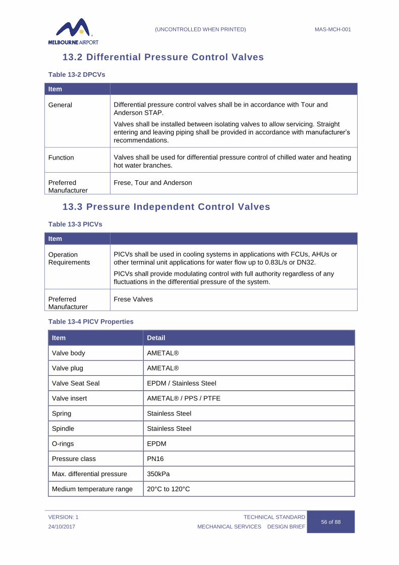
(UNCONTROLLED WHEN PRINTED) MAS-MCH-001
VERSION: 1 TECHNICAL STANDARD
24/10/2017 MECHANICAL SERVICES DESIGN BRIEF 56 of 88
13.2 Differential Pressure Control Valves
Table 13-2 DPCVs
Item
General Differential pressure control valves shall be in accordance with Tour and
Anderson STAP.
Valves shall be installed between isolating valves to allow servicing. Straight
entering and leaving piping shall be provided in accordance with manufacturer’s
recommendations.
Function Valves shall be used for differential pressure control of chilled water and heating
hot water branches.
Preferred Manufacturer
Frese, Tour and Anderson
13.3 Pressure Independent Control Valves
Table 13-3 PICVs
Item
Operation Requirements
PICVs shall be used in cooling systems in applications with FCUs, AHUs or
other terminal unit applications for water flow up to 0.83L/s or DN32.
PICVs shall provide modulating control with full authority regardless of any
fluctuations in the differential pressure of the system.
Preferred Manufacturer
Frese Valves
Table 13-4 PICV Properties
Item Detail
Valve body AMETAL®
Valve plug AMETAL®
Valve Seat Seal EPDM / Stainless Steel
Valve insert AMETAL® / PPS / PTFE
Spring Stainless Steel
Spindle Stainless Steel
O-rings EPDM
Pressure class PN16
Max. differential pressure 350kPa
Medium temperature range 20°C to 120°C
(UNCONTROLLED WHEN PRINTED) MAS-MCH-001
VERSION: 1 TECHNICAL STANDARD
24/10/2017 MECHANICAL SERVICES DESIGN BRIEF 57 of 88
Item Detail
Typical Detail FCU – CHW Connection with PICV
13.4 Control Valve Arrangements for AHU’s & FCU’s
Table 13-5 AHU and FCU LTHW Flow Control Valves
Item
Operational Requirements
For the terminal control (FCU and AHU) of the LTHW (80°C), 3-way valve control strategy should be adopted. This strategy shall be applied to avoid low flow situations through the high temperature heat exchangers and overheating of heat exchangers.
Melbourne Airport has adopted dynamic flow balancing using automatic balancing systems instead of static balancing. Tour and Anderson STAD or STAF valves shall not be used for balancing.
Tour and Anderson STAD and STAF valves should be used as flow measuring devices where required.
Dynamic-Automatic Flow Control Valves using stainless steel cartridge to maintain specific flow rate independent of pressure fluctuations within a system should be used. These valves should use terminal balancing with factory pre-set flow rate that is maintained at selected pressure differential range.
Automatic balancing valves should be used in series with 3-way valves.
Valve accuracy ±5%.
High flows For higher flows Tour Anderson TA AutoFlow WS should be used in series with 3-way control valves, from DN65 up to DN350 and from 5L/s to 360L/s.
Automatic balancing valve AutoFlow WS (Wafle-Style) should have ductile iron body, stainless steel flow cartridge, accuracy of 5% over 95% of the control range. The number of flow cartridges required shall be determined by the L/s requested. Studs, nuts and 2 drilled and tapped ports with extended pressure/temperature test points shell be standard.
Energy Efficiency This 3-way control strategy is not energy efficient and energy saving using VSDs on the pumps cannot be utilised. As an energy saving option system with by-pass providing constant minimum flow through heat exchanger could be designed. 3-way control valves should be provided for the last units on the pipe run. This option shall be discussed and approved by Melbourne Airport.
Preferred Frese, Tour and Anderson

(UNCONTROLLED WHEN PRINTED) MAS-MCH-001
VERSION: 1 TECHNICAL STANDARD
24/10/2017 MECHANICAL SERVICES DESIGN BRIEF 58 of 88
Item
Manufacturer
Typical Detail – 3 Pot for LTHW
Table 13-6 AHU and FCU CHW Flow Control Valves
Item
Operational Requirements
For the CHW AHU terminal control, 2-way control strategy shall be adopted with 3-way control valves for the last unit on the end of the pipe run to provide minimum flow for the pumps and the available designed water temperature to the rest of the units on that run.
Melbourne Airport has adopted dynamic flow balancing using automatic balancing systems instead of static balancing. Tour and Anderson STAD or STAF shall not be used for balancing.
Dynamic automatic flow control valves using stainless steel cartridge to maintain specific flow rate independent of pressure fluctuations within a system shall be used. These valves should be used terminal balancing with factory pre-set flow rate that is maintained at selected pressure differential range.
Automatic balancing valves should be used in series with 2-way control valves.
Automatic balancing valves such as Tour and Anderson TA AutoFlow AC up to 50mm and 4.42L/s or similar shall be used.
Valve accuracy ±5%.
High flows For higher flows Tour Anderson TA AutoFlow WS shall be used in series with 2-way valves, from DN65 up to DN350 and from 5L/s to 360L/s.
Automatic balancing valve AutoFlow WS should have ductile iron body, stainless steel flow cartridge, accuracy of 5% over 95% of the control range. The number of flow cartridges required is determined by the l/s requested. Studs, nuts and 2 drilled and tapped ports with extended pressure/temperature test points shell be standard.
Energy Efficiency This 3-way control strategy is not energy efficient and energy saving using VSDs on the pumps cannot be utilised. As an energy saving option system with by-pass providing constant minimum flow through heat exchanger could be designed. 3-way control valves should be provided for the last units on the pipe run. This option shall be discussed and approved by Melbourne Airport.
Preferred Manufacturer
Tour and Anderson or approved equal

(UNCONTROLLED WHEN PRINTED) MAS-MCH-001
VERSION: 1 TECHNICAL STANDARD
24/10/2017 MECHANICAL SERVICES DESIGN BRIEF 59 of 88
Item
Typical Detail – 2 Port for CHW Coils
Typical Detail – 3 Port Control for CHW Coils at end of run
13.5 High Temperature Heating Hot Water Control Valves
Table 13-7 HTHHW Control Valves
Item
Operational Requirements
HTHW pipework of diameters greater than 50mm shall be fitted with 2 control valves sized for 1/3, 2/3 flow rates respectively to account for low flow conditions.
Branching HTHW pipework shall be fitted with flow control valves.
Heat Exchanger Connections
In addition to control valves, the HTHW side of the heat exchanger shall be provided with a direct acting 2-port safety shut off valve on the incoming flow pipework to the heat exchanger. The valve should be normally open and linked to a dedicated temperature sensor (separate to other sensor used for normal operation) monitoring shell temperature of the heat exchanger. Should maximum temperature be exceeded (adjustable via the BMS) the shut of valve shall be actuated to the shut position. The shut off valve position should be monitored by the BMS and an alarm shall be raised with the BMS operator if a ‘shut off valve closed’ signal is returned.
Preferred Manufacturer
Sauter valves shall be VUG (2 way through flange valve) or BUG (3 way flange valve) to suit AVF234F132 and AVM234F132 series actuators.

(UNCONTROLLED WHEN PRINTED) MAS-MCH-001
VERSION: 1 TECHNICAL STANDARD
24/10/2017 MECHANICAL SERVICES DESIGN BRIEF 60 of 88
14 Thermal Energy Metering Requirements
Below are the general requirements for thermal metering of mechanicals services at Melbourne
Airport:
Table 14-1 Thermal Metering Requirements
Item
General Thermal Energy Meters shall be in accordance with all relevant Australian Standards
Data Points All thermal meters to provide readings for the following parameters:
Flow (l/s)
Flow Temp (ºC)
Return Temp (ºC)
Energy (kWh)
Water Volume (mᵌ/h)
Meter Class EN1434 Class 1
Accuracy ±1%
Requirements Meters must provide measurements at a 15 minute resolution period or better, synchronised to perform readings at a common time period at: 00:15:30:45 minutes past each hour.
Provide on board display of measured values.
Provide on board non-volatile memory of current measured values
BMS Interface Provide Modbus interface
Preferred Manufacturer
Pricam (Surface Mounted), Belimo (In-Line)

(UNCONTROLLED WHEN PRINTED) MAS-MCH-001
VERSION: 1 TECHNICAL STANDARD
24/10/2017 MECHANICAL SERVICES DESIGN BRIEF 61 of 88
15 Mechanical Electrical Installations
Table 15-1 Mechanical Electrical Installations – General Requirements
Item
General Mechanical / electrical installations shall be in compliance with AS 3000
All electrical equipment shall be in accordance with AS 4251
Contractors shall ensure all works are in accordance with:
AS 3008.1.1; AS 3013; AS 3947.2; and AS 3439
Drawings The drawings shall show the following information: Fault current and discrimination calculations; Full circuit breaker protective level settings; Manufacturer's name and catalogue number of any standard equipment; The general arrangement of equipment; Full details of cabinet construction and dimensions; The method of supporting busbars and protection/control equipment; A description of all materials to be used; Clearances between live parts and live parts to earth; Wiring diagrams and schematics of instruments, protection and control circuits detailing wire and terminal numbers;
Fixing of Electrical Infrastructure
Proprietary fasteners shall be used capable of transmitting loads imposed and sufficient to ensure the secure fixing of the equipment under all modes of operation.
Zones where drilling or penetration is prohibited shall be avoided.
Continuity of Supply
Where electrical facilities exist on the site and / or premises, these facilities shall be maintained to suit the convenience of consumers. Any interruption to the electricity supply shall only be made with the written consent of those affected.
Table 15-2 Electrical Distribution Network’s
Item
Cables and Cable Support
Wiring shall be TPI cables in conduit or cable duct, or PVC / PVC or fire rated cables on cable tray with conductors rated to suit the respective load circuit, except where specifically stated otherwise.
Wiring shall be carried out using the ‘looping in’ principle and the use of connectors or joining of cables will not be permitted.
Wiring within the plantroom areas shall be exposed, enclosed in conduit or wiring duct or supported on cable tray, but shall be concealed within the fabric of the building in areas external to the plantroom, unless otherwise specified.
Wiring installed on cable tray shall be mechanically protected to a height of 1.8m
Minimum size of conductors shall of 2.5mm² for power and 1.5mm² for control wiring using multistrand copper conductors.
Catinary wire used for cable installation will be heavy duty 7 / 125mm² sizes only.
Conduit and Fittings
Where conduits cross structural joints a section of flexible conduit or similar shall be inserted to extend a minimum of 230mm on each side of the joint, and shall comply with the electrical standard detail drawing enclosed herein.
Conduits run in slabs poured on filling shall be contained within the concrete and

(UNCONTROLLED WHEN PRINTED) MAS-MCH-001
VERSION: 1 TECHNICAL STANDARD
24/10/2017 MECHANICAL SERVICES DESIGN BRIEF 62 of 88
Item
not in contact with the fill.
Cable Tray Except where otherwise specified the trays selected shall allow at least 20% spare capacity for future cables.
15.1 Mechanical Services Switchboards
Table 15-3 Mechanical Services Switchboards
Item
General All mechanical services shall be powered from dedicated MSSBs
Each switchboard shall comprise of a sheet metal enclosure containing the following equipment: A load break isolator that isolates all incoming supplies to the switchboard; Means of isolating and protection (circuit breakers and overloads) for each motor circuit; Contactors or starters for each motor circuit, including the necessary protection devices; Led cluster pilot lights for run, fault and fire alarm, complete with lamp test facilities; “auto-off-manual’ double pole switches for all motor start circuits; and Power metering to all incoming supplies
The switchboard doors shall be folded and braced to prevent flexing and distortion
Segregation Internal: Form 2b or above
Heavy current switchboard >800A: Form 3b or above
Degree of Protection
Internal: IP54
External: IP65
Spare Capacity A minimum of 25% spare space and capacity for future circuits shall be provided.
Electrical Metering Mechanical Services Switchboards that provide power supply to Melbourne
Airport engineering infrastructure will be revenue metered using EDMI meters
connected to Melbourne Airports SMART Metering System.
Sub meters used for trend monitoring purposes to be Schneider or equivalent.
Comms Rooms Mechanical Services Switchboards that provide power supply to Melbourne
comms rooms will be revenue metered using EDMI meters connected to
Melbourne Airports SMART Metering System.
Sub meters used for trend monitoring purposes to be Schneider or equivalent.
Retails Tenancies Every retail tenancy to be provided with dedicated MSSB
Retail MSSBs to be fed from local main MSSB
Sub-metering not required
Preferred Manufacturer
Schneider, NHP, Moeller

(UNCONTROLLED WHEN PRINTED) MAS-MCH-001
VERSION: 1 TECHNICAL STANDARD
24/10/2017 MECHANICAL SERVICES DESIGN BRIEF 63 of 88
15.3 Variable Speed Drives
Table 15-4 Variable Speed Drives
Item
General Variable Speed Drives (VSDs) shall be in accordance with AS/NZS 3947.4.2.
VSDs shall be compatible with BMS Lon communication protocol.
Each VSD shall be selected on the basis of maximum motor full load “nameplate” amps and not motor kW rating.
Enclosure Enclosures shall be protected against the ingress of dust and water to IP66 in accordance with AS 60529
VSD’s above 140A may be a minimum IP54
Environmental VSD’s shall be in accordance with the following environmental limits:
Ambient Temperature (storage): -20ºC to +70°C
Ambient Temperature (operation): Capable of 0ºC to 40°C continuous at
motors FLC
Relative Humidity: 5% to 95% non-condensing
Where higher ambient temperatures are specified the VSD shall be de-rated according to documented manufacturer de-rating requirements.
Power Factor VSD’s shall provide an input power factor not less than 0.98.
Harmonic Distortion
The carrier frequency of the PWM inverter shall be asynchronous to limit harmonic distortion of the 5th and 7th bandwidths to < 3%.
VSD’s shall include a substantial ‘DC Bus Harmonic Reduction Reactor’ in accordance with AS/NZS 61000.3.12for applicable to equipment up to 75 A, and AS 61000.3.4:2007 for equipment above 75A. The DC bus choke shall be integral to the VSD’s IP66 Enclosure and part of the original design (not add-on).
Control Panel & Display
Provide a control panel with soft touch keypad and alpha/numeric LCD display to facilitate commissioning and adjustment of variables and to display status including faults.
Preferred Manufacturer
Danfoss VLT Range
15.4 Harmonic Distortion
Item
Harmonic Distortion
The carrier frequency of the PWM inverter shall be asynchronous to limit harmonic distortion of the 5th and 7th bandwidths to < 3%.
VSD’s shall include a substantial ‘DC Bus Harmonic Reduction Reactor’ in accordance with AS/NZS 61000.3.12for applicable to equipment up to 75 A, and AS 61000.3.4:2007 for equipment above 75A. The DC bus choke shall be integral to the VSD’s IP66 Enclosure and part of the original design (not add-on).

(UNCONTROLLED WHEN PRINTED) MAS-MCH-001
VERSION: 1 TECHNICAL STANDARD
24/10/2017 MECHANICAL SERVICES DESIGN BRIEF 64 of 88
16 Labelling and Identification
Table 16-1 Colour Schedule
System Colour Label Colour
Chilled Water Blue Black
Heating Water Red White
Condenser Water Green Black
Feed Water Nil White
Condensate Nil Black
Exposed Ductwork (Other than plantrooms)
Nil Black
Ductwork, Conditioner Casings, Air Handing Units, Filter Plenums (in plantrooms)
Nil Black
Electricity (Conduits, Ducts &
Motors)
Orange Black
Danger AS1318 Black & Yellow diagonal stripes (45° 25mm wide)
Equipment To match respective services
Valve & Pipeline Fittings
To match respective services Black
Belt guards AS1318 Black & Yellow
Diagonal Stripes (45° 25mm
wide)
Switchboards Non-essential - Orange,
Essential - Red, Uninterruptible
Power Supply - Blue
Black

(UNCONTROLLED WHEN PRINTED) MAS-MCH-001
VERSION: 1 TECHNICAL STANDARD
24/10/2017 MECHANICAL SERVICES DESIGN BRIEF 65 of 88
17 Noise & Vibration Control Requirements
Table 17-1 Acoustic Design Criteria for Mechanical Systems
Item
General Building services noise levels shall be in accordance with AS 2107 and to the
internal noise levels directed by the acoustic consultant.
In no instances shall operating mechanical services equipment exceed 85 dBA
at 1m.
Vibration Isolation Mounts
Isolate all equipment incorporating rotating or reciprocating machinery on anti-
vibration mounts. Provide these mounts with transmissibility low enough so as
not to cause excessive vibration of the building structure.
All items of plant, except those located in a basement, shall be isolated to a level
of 98% vibration efficiency at the dominant disturbing frequency.
Flexible Connections
All items of rotating and reciprocating equipment shall be connected to their respective piping and electrical power supplies with flexible connections
Machinery Bases Mount all machinery on integral rigid bases which do not deflect excessively under the weight of the equipment or due to the reactions between motors, driven machines etc. To avoid base resonances, the natural flexural frequency of the isolator base must be a minimum of 10% greater than the maximum rotational speed of the motor or driven machine.
Pipe and Duct Hangers and Mountings
Provide isolation mounts and connections for pipework and ductwork manufactured by approved manufacturers and be of approved materials.
Incorporate in all hangers’ height adjustment by means of a nut on the hanger rod.
Equipment Plinths Concrete plinths shall be provided under all items of floor mounted and be a minimum of 100mm high

(UNCONTROLLED WHEN PRINTED) MAS-MCH-001
VERSION: 1 TECHNICAL STANDARD
24/10/2017 MECHANICAL SERVICES DESIGN BRIEF 66 of 88
18 Water Treatment Requirements
Below are the general requirements for water treatment, with respect to mechanical services at
Melbourne Airport:
Table 18-1 General Requirements
Item
General Water treatment shall be in accordance with the following standards:
AS/NZS 3666.1; AS/NZS 3666.2; AS/NZS 3666.3; and HB 32
Regulations Water treatment shall be in accordance with the following regulations:
Building (Legionella) Act; Health (Legionella) Regulations; and Building and plumbing regulations under the Building Act
18.1 Design & Installation Requirements
Table 18-2 Design & Installation Requirements
Item
Performance Water treatment systems shall be provided for the control of the following:
Open systems: Scale formation, corrosion, sludge accumulation and
microbiological growth including Legionella species; and
Closed systems: Scale formation, corrosion, sludge accumulation and
microbial growth.
Compatibility Water treatment systems shall suit the fluid being treated, and the as-installed system construction.
Water treatment shall be compatible with the current Melbourne Airport dosing regimen.
The Contractor shall submit a dosing implementation plan to Melbourne Airport for approval prior to commencement on site. This plan shall identify the following as a minimum:
Dosing chemicals / agents to be used;
Dosing chemicals/agents are the same as those currently used by
Melbourne Airport;
Volume of system to be dosed;
Quantity of dosing chemical/agent to be used; and
Dosing method statement including safety measures.
Corrosion Rates Water treatment shall limit corrosion rates to the following:
Mild steel and iron: 0.15mm/year;
Stainless steel: 0.05mm/year, with no pitting; and
Copper: 0.012mm/year.
Chemicals Sufficient quantities of chemicals shall be supplied to treat the water from the time of initial filling to beyond the end of the maintenance period.

(UNCONTROLLED WHEN PRINTED) MAS-MCH-001
VERSION: 1 TECHNICAL STANDARD
24/10/2017 MECHANICAL SERVICES DESIGN BRIEF 67 of 88
Item
Test Loops Loops shall be provided in water circulating systems containing corrosion
coupons representing the respective metals in the system in accordance with
ASTM D 2688.
Coupons shall be replaceable every:
Steel 3 months
Copper 6 months
Stainless Steel 6 months
Marking Piping and storage vessels containing hazardous materials shall be identified.
If hazardous chemicals are to be stored, safety signs shall be provided in accordance with AS 1319.
18.2 Closed Systems
Table 18-3 Water Treatment Systems – Closed Systems
Item
General For each independent system to be treated, a separate chemical dosing system shall be provided consisting of a by-pass slug-dose feeder vessel employing discharge flow to flush chemicals into the system.
Feeder Vessels A storage tank shall be provided capable of withstanding the maximum pump
pressure.
The following shall be provided:
A funnel;
DN15 piping and valve for adding chemicals;
Vent line with valve;
DN15 drain line with valve discharging to drain; and
DN15 outlet line with valve.
Filters Proprietary filter systems shall be used consisting of storage tanks, piping,
valves, instruments timers and controls to provide automatic backwashing.
Backwash system shall be complete with piping, valves, pressure gauges and
ancillary devices to show the need for backwash.
Backwash cycle shall be initiated by automatic timer with provision for manual
override.
Side-stream filtration equipment shall be arranged by the WTSP
Automatic pressure initiated self-cleaning Screen filtration such as VAF or
approved equivalent (employing an appropriate screen size no greater than
100 micron) with sufficient agitation of cooling tower basins to ensure silt,
sediment and organic material does not settle in cooling tower basins.
Filtration systems using large volumes of water to backflush such as media
filters shall not be acceptable, filtration systems using only timed backflush
are not acceptable, systems that do not remove organic material such as
centrifugal or cyclone separators are also not acceptable. Bag filters are not
considered suitable for cooling tower filtration.
Requirements Provide a skid mounted separator filtration system of Lakos manufacture or

(UNCONTROLLED WHEN PRINTED) MAS-MCH-001
VERSION: 1 TECHNICAL STANDARD
24/10/2017 MECHANICAL SERVICES DESIGN BRIEF 68 of 88
Item
equal for each cooling tower to remove suspended solids down to 5 microns of
specific gravities between the ranges of 1.8 to 2.8.
Manufacture the unit from stainless steel suitable for locating in the external
corrosive environment.
Manufacture the unit from powder coated carbon steel, where the unit is
protected from the external corrosive environment.
The unit shall incorporate the following:
Separator
Pump
Suction Strainer
Solids Collection Vessel
Indicator Package
Electrical Control
Piping
Valves
Skid Plate
Provide a tank sweeper Eductor system of Lakos manufacture or equal. Size
and configure the system to optimise the separator performance and maximise
water circulation with minimum pump flow.
Manufacture the Eductor nozzles from polypropylene or approved equal highly
corrosion resistant material.
Table 18-4 Completion & Acceptance Requirements
Item
Acceptance Tests For bacteria including Legionella species, sample and test shall be completed by a NATA-accredited testing authority.
Legionella analysis shall be in accordance with AS/NZS 3896 & 3666
Bacteria analysis / total plate count shall be in accordance with AS 4276.3.1.
Test reports shall be prepared and submitted to Melbourne Airport.
Pre-Treatment Chemicals shall be supplied for pre-cleaning, cleaning and flushing of mechanical piping systems. Instructions and supervision shall be provided to ensure correct use of chemicals.
Initial Treatment Chemical Cleaning and Flushing
Detergent flushing shall take place once hydrostatic testing has been completed, release the testing water and flush piping systems using non-foaming alkali detergent solution.
Cleaning and flushing shall be completed by introducing cleaning chemicals to piping systems and circulate continuously for at least 24 hours, with control and manual valves open. Systems shall be drained and clean strainers and flushed with clean water until cleaning chemicals are removed.
Initial Treatment
As the water is initially introduced into any section of the system by the

(UNCONTROLLED WHEN PRINTED) MAS-MCH-001
VERSION: 1 TECHNICAL STANDARD
24/10/2017 MECHANICAL SERVICES DESIGN BRIEF 69 of 88
Item
mechanical contractor, the WTSP shall simultaneously introduce a suitable oxygen scavenger/corrosion inhibitor. The chemical is to be added at constant frequency to the ingress water, at the point of ingress, either manually or by automation. The mechanical contractor shall provide any mechanical/electrical/plumbing and similar facilities which may be needed for safe dosing to take place.
When the mechanical contractor begins circulating the water through the System, the WTSP shall test the treated water at different points in the System, given the presence of proper sampling points. The WTSP shall test the treated water at regular intervals for the duration of the hydrostatic test, dosing more oxygen scavenger/corrosion inhibitor if required. The hydrostatic test itself shall be performed by the mechanical contractor. The mechanical contractor may choose to perform the chemical dosing and testing, after consulting the WTSP in respect of advice on safety and other details.
Alkaline Clean
Subsequent to the hydrostatic test discussed above, and when all galvanised, aluminium and other sensitive components have been by-passed by the mechanical contractor, the WTSP shall dose the System with a suitable alkaline chemical clean agent designed to disperse solids, remove oil and grease and leave a clean waterside surface. The treated water shall be circulated for around 24 hours through the entire System, except for the by-passed areas. A water bleed is then set to flush out undesirable solids, and the System allowed to make-up with raw water until the pH, clarity and general appearance of the System water, at any point in the System, is clean and indistinguishable from that of the ingress raw water. The mechanical contractor shall ensure that raw water will make-up adequately during the bleed process, given the bleed rate. The mechanical contractor may choose to perform the chemical dosing and testing, after consulting the WTSP in respect of advice on safety and other details.
Disinfection Clean Subsequent to the alkaline clean referred to in Section 1.9, disinfection clean shall be performed, in accordance with the Public Health and Wellbeing Act 2008.
Commissioning Immediately after the disinfection clean, passivation of the System waterside shall be achieved using a suitable corrosion and scale inhibitor. A slug-dose of a “kill” amount of a non-oxidising biocide shall also be performed immediately after passivation is achieved. The water treatment equipment must then be activated, corrosion coupons inserted, and dosing tanks/drums adequately stocked with chemicals.
Preferred Manufacturer
Hydrochem or equal and approved.

(UNCONTROLLED WHEN PRINTED) MAS-MCH-001
VERSION: 1 TECHNICAL STANDARD
24/10/2017 MECHANICAL SERVICES DESIGN BRIEF 70 of 88
19 Automatic Controls and Building Management
System Requirements
The contractor shall provide for BCMS points in accordance with the following sections and where
required include additional controls points as necessary to suit the equipment specified.
Refer to APAM Standard – MAS-MCH-007 – Automatic Controls and Building Management Systems
for further guidance.
19.1 Typical Controls Schematics (SLD’s)
A list of typical controls schematics of main mechanical equipment is provided below:
System Typical Controls Schematic
Air Handling Unit
(AHU)

(UNCONTROLLED WHEN PRINTED) MAS-MCH-001
VERSION: 1 TECHNICAL STANDARD
24/10/2017 MECHANICAL SERVICES DESIGN BRIEF 71 of 88
System Typical Controls Schematic
Fan Coil Unit
(FCU)
Package Air Conditioning
Unit
(PAC)
Variable Air Volume Unit
(VAV)

(UNCONTROLLED WHEN PRINTED) MAS-MCH-001
VERSION: 1 TECHNICAL STANDARD
24/10/2017 MECHANICAL SERVICES DESIGN BRIEF 72 of 88
System Typical Controls Schematic
Typical Exhaust Air
System
Variable Speed Fan

(UNCONTROLLED WHEN PRINTED) MAS-MCH-001
VERSION: 1 TECHNICAL STANDARD
24/10/2017 MECHANICAL SERVICES DESIGN BRIEF 73 of 88
System Typical Controls Schematic
Constant Speed Fan
Split Air Conditioning
Unit

(UNCONTROLLED WHEN PRINTED) MAS-MCH-001
VERSION: 1 TECHNICAL STANDARD
24/10/2017 MECHANICAL SERVICES DESIGN BRIEF 74 of 88
System Typical Controls Schematic
Chilled Water
(CHW)

(UNCONTROLLED WHEN PRINTED) MAS-MCH-001
VERSION: 1 TECHNICAL STANDARD
24/10/2017 MECHANICAL SERVICES DESIGN BRIEF 75 of 88
System Typical Controls Schematic
Condenser Water
System
(CCW)
Heating Hot Water
(HHW)

(UNCONTROLLED WHEN PRINTED) MAS-MCH-001
VERSION: 1 TECHNICAL STANDARD
24/10/2017 MECHANICAL SERVICES DESIGN BRIEF 76 of 88
System Typical Controls Schematic
Heat Exchanger (HTHHW-
LTHW)
Variable Speed Pump

(UNCONTROLLED WHEN PRINTED) MAS-MCH-001
VERSION: 1 TECHNICAL STANDARD
24/10/2017 MECHANICAL SERVICES DESIGN BRIEF 77 of 88
System Typical Controls Schematic
Constant Speed Pump
Thermal Energy Meter

(UNCONTROLLED WHEN PRINTED) MAS-MCH-001
VERSION: 1 TECHNICAL STANDARD
24/10/2017 MECHANICAL SERVICES DESIGN BRIEF 78 of 88
20 Access Requirements
Design
The design of the plant access systems should consider the 24/7 access needs of the facility and
should provide safe trade access in all weather conditions. The need for temporary access systems
should be eliminated where possible to reduce risk and potential impact on operations. Access to
valves, inspection panels or control mechanisms, for the purpose of conducting scheduled
maintenance, is to be provided and should not be reliant on the use of portable ladders, temporary
scaffold or mechanical lifting systems (EWP).
The type of access system should be commensurate with the access needs of the site and any
constraints that may be present due to the nature of the facility. Internal access from existing plant
rooms, on the main airport concourse, is the most practical solution while external stairs and ladders
would be preferred on the outer buildings. Where internal access is selected, it should be configured
to have the lowest possible impact on the operations of the facility. Access control (security) should be
considered as a component of the selection and positioning of any access systems.
Plant Rooms/Enclosures
The priority is for plant systems to be centrally located within plant rooms, plant enclosures or plant
decks. This reduces the requirement for trades to access elevated areas or move across vast
sections of roof area to conduct scheduled maintenance. Access to these types of areas should be
via access doorways linked to fixed stairs and walkways. The use of step or rung type ladders should
be avoided for access to plant rooms or elevated plant platforms, unless there are constrictions due to
available space which makes the installation of stairs impractical. The outer perimeter of any elevated
plant deck is to be enclosed with AS 1657-2013 compliant guard railing. Where an elevated plant
deck is positioned above a work area, walkway or fall edge then kick boards must be included.
Elevated Roof Areas and Plant Access
Fixed access should be established to plant systems located on elevated roof areas. The access is to
be passive and allow trades to access the plant units without the use of portable ladders or harnessed
based fall protection systems (vertical ladders with cable safety systems should be avoided). Fixed
ladders should include cages with guarded platforms at the ladder head. Where the ladder is
providing the initial point of access to a roof, the ladder is to include a lockable gate system to provide
access control. Vertical ladders should be avoided unless there are space constrictions that prevent a
ladder from being installed at the optimal angle in accordance with AS 1657-2013 (75° for rung type
ladders).
Internal access through suspended panel or plaster ceilings (where fixed ladders are not possible) are
to include a pull-down ladder system which is suspended from the roof structure. The internal roof
cavity between pull-down ladder and hatch is to have a fixed access ladder in place and should be
configured to allow seamless directional travel (no change of direction from ground to roof) between
the pull down and fixed ladders.
Where internal access via a roof hatch is required, the hatch should have a minimum opening of
800mm x 1000mm. Sliding hatch mechanisms are preferred; however, if hinged hatches are utilised
then gas struts are required to support the hatch during operation. A guard rail surround is to be
included to enclose the hatch opening and is to have fixed grab handles (exit stiles) to aid in transition
through the hatch. The use of extendible stile units on ladders should be avoided.

(UNCONTROLLED WHEN PRINTED) MAS-MCH-001
VERSION: 1 TECHNICAL STANDARD
24/10/2017 MECHANICAL SERVICES DESIGN BRIEF 79 of 88
Walkways and Guard Rails
Walkways are to be established from the point of roof access (doorway, stair, ladder or hatch) to each
plant unit. Where walkways are located within two meters of a fall edge or non-trafficable surface, AS
1657-2013 guard railing is required to close out the unprotected edge or hazard. Where walkways
cross non-trafficable skylight sheeting, a minimum of two meters of mesh protective covers are to be
installed on both sides of the walkway. Alternatively, guard railing can be installed on each side of the
walkway to close out the hazard. Where walkways run within two meters of a non-trafficable skylight
sheet, protective mesh or guard rails are required to close out the hazard.
Walkways are to be of a metal, aluminium (preferred) or Fibre (not preferred) construction and are to
be supported above the roof sheeting on support battens. Fibre walkways are not to be installed
directly onto the roof sheeting and alternate fixing methods should be sourced from the manufacturer.
Fixing of the battens to the roof is to be via bulbtite rivet type and must include a membrane tape seal.
Ceiling Space Plant Access
Where plant systems are located within ceiling spaces, fixed passive access should be established.
The physical constraints of these types of areas (low headroom or services) will create obstacles that
prevent fully compliant access in accordance with AS 1657-2013; however, every effort should be
made to comply with the standard.
Non-trafficable ceilings should be treated as fall hazards. Areas beneath gantries or celling space
work platforms will be considered drop zones; however, operational constraints may prevent areas
from being closed off. Access gantries should be enclosed with AS 1657-2013 compliant guard railing
on both sides which should include kickboards. The gantry flooring should be constructed to prevent
items from being dropped through it.
Specialised Access
Plant systems should be designed to allow maintenance to be conducted from ground level or from a
fixed platform. All efforts should be made at the design phase to eliminate the requirement to access
plant systems utilising specialist access equipment. However; this is not always possible due to the
constraints of the facility and existence of older plant configurations. Where these issues arise
specialist access systems will be required. The use of EWP is an effective means of access and can
be employed within the facility or externally to conduct works. The impact, of this type of access
system, on operations should be considered at the design phase.
The use of complex harnessed based fall protection or rope access systems may be required where
there is an inability to access via other means. Where ongoing scheduled maintenance or critical
services are involved, these types of access methods should be avoided.
Compliance
Any designed and installed plant access systems must comply with AS 1657-2013 Fixed platforms,
walkways, stairways and ladders – Design, construction and installation. Purpose deigned systems
are to be supplied with detailed shop drawings and should clearly state that the design meets
Australian Standards. Where proprietary systems (modular type) are being utilised, the installed
systems must meet manufacturer’s specifications and contracted installers must be trained and
certified to install the products. All installed systems must be clearly marked with the installer’s
information and date of installation. This must be displayed on a permanent plate or label in a
prominent position. Ongoing maintenance should be conducted to ensure that the access systems,
stairs, ladders, guard rails and walkways are in a serviceable condition.

(UNCONTROLLED WHEN PRINTED) MAS-MCH-001
VERSION: 1 TECHNICAL STANDARD
24/10/2017 MECHANICAL SERVICES DESIGN BRIEF 80 of 88
Handover documentation should be supplied as a component of any plant access system installation.
This should include detail in relation to the products utilised for modular systems and design loadings
for complex purpose-built access system such as suspended or cantilevered platforms.

(UNCONTROLLED WHEN PRINTED) MAS-MCH-001
VERSION: 1 TECHNICAL STANDARD
24/10/2017 MECHANICAL SERVICES DESIGN BRIEF 81 of 88
21 Operation of Mechanical Services under Fire Alarm
Item
Requirements Mechanical Services equipment shall be connected to essential and non-
essential mechanical switchboards or switchboard sections as indicated in the
schedules.
The Project shall update the Melbourne Airport Fire/Mech matrix as part of
project delivery
The Designer shall submit for approval an updated Fire/Mech Matrix, taking into
account new equipment or modifications to existing equipment, to the Melbourne
Airport Project Sponsor prior to commencement of works on site.
The Contractor shall confirm the final Fire/Mech Matrix prior to practical
completion and demonstrate that switching/operation of mechanical equipment
occurs as described under a simulated fire event as part of the commissioning
process.
Operation of Non-Essential Equipment
The Fire Protection Sub-Contractor will provide wiring to a fire relay in the non-
essential mechanical switchboard or switchboard section.
The Sub-Contractor shall provide all necessary interlocks to ensure shut down of
the non-essential air handling plant in a fire alarm situation.
Fire relays shall be provided within the mechanical switchboard to operate the
mechanical system as required in fire mode. Co-ordinate with the Fire Protection
Sub-Contractor and obtain details of the required incoming signal voltage prior to
installing the relays.
Relays shall be of a type suitable for operation in conjunction with the Fire
Indicator Panel with respect to segregation of voltages and to the requirements
of the relevant Fire Authority.

(UNCONTROLLED WHEN PRINTED) MAS-MCH-001
VERSION: 1 TECHNICAL STANDARD
24/10/2017 MECHANICAL SERVICES DESIGN BRIEF 82 of 88
22 Testing, Balancing & Commissioning Requirements
22.1 Allocation of Commissioning Responsibilities
Specifying System Commissioning Activities
Design Activity Responsibility Comments
Cns’tant Cont’r Other
Design
D.1) Ensure that the
selected systems will meet
the employer’s brief and that
their commissioning
requirements are compatible
with any project restraint
concerning sectional
handover/phasing.
The contractor is responsible for those services, systems or work elements design by them and/or specialist sub-contractors appointed by them.
D.2) Identify and incorporate
into system designs the
essential components and
features necessary to enable
the proper preparation and
commissioning of building
services.
Note as D.1
D.3) Review all designs to
ensure that systems can be
properly prepared, and are
commissionable.
Note as D.1
D.4) Prepare the
commissioning specification. Note as D.1
Management
D.5a) Produce a
commissioning method
statement and logic diagram
for integration into the
building contractor’s
construction and finishes
programmes.
It is for the Contractor is to demonstrate to the local Building Control office that the person(s) providing this report are suitably qualified.
D.5b) Produce a
“commissioning plan” as
required by Part L2 of the
Building Regulations.
It is for the Contractor is to demonstrate to the local Building Control office that the person(s) providing this report are suitably qualified.
D.6) Produce a flushing,
chemical cleaning and water
treatment method statement,

(UNCONTROLLED WHEN PRINTED) MAS-MCH-001
VERSION: 1 TECHNICAL STANDARD
24/10/2017 MECHANICAL SERVICES DESIGN BRIEF 83 of 88
Specifying System Commissioning Activities
Design Activity Responsibility Comments
Cns’tant Cont’r Other
logic diagram and
programme for integration
into the building contractor’s
construction, commissioning
and finishes programmes.
D.7) Attend commissioning
meetings as necessary OR
Arrange and chair
commissioning meetings as
necessary.
Give notice to the Consultant of when meetings are taking place.
D.8) Comment on the
adequacy of systems for
commissioning as detailed
on specialists’ drawings and
manufacturers’ shop
drawings prior to actual
manufacture at
works. Ensure comments
are incorporated into finished
products.
D.9) Carry out site
inspections, to ensure that
the commissioning facilities
are being installed. Check
compliance with specified
guides and standards.
D.10) Monitor the on-going
progress of the procurement,
manufacture, installation and
commissioning of all plant
items.
D.11) Assess the effects of
any anticipated delays to the
services installation and the
completion of interfaces with
the building works critical to
the commissioning
programme. Formulate
strategies to overcome
potential delays.
D.12) Establish an agreed
set of pro forma
documentation relating to the
commissioning and testing of
plant and systems.
Issue to project consultant for comments.
D.13) Approve the proposed

(UNCONTROLLED WHEN PRINTED) MAS-MCH-001
VERSION: 1 TECHNICAL STANDARD
24/10/2017 MECHANICAL SERVICES DESIGN BRIEF 84 of 88
Specifying System Commissioning Activities
Design Activity Responsibility Comments
Cns’tant Cont’r Other
set of instruments of the
commissioning and testing
works.
D.14) Ensure that the
instrumentation is
periodically calibrated as
necessary and records
retained.
D.15) Witness the flushing,
cleaning and treatment of
systems in accordance with
the specification.
D.16) Witness pre-
commissioning activities in
accordance with the
specification.
D.17a) Commission all
systems to methods, logic
and programme and record
results.
D.17b) Witness specified
demonstration of system
D.18) Witness and record
the specified demonstration
and testing of plant items and
systems in accordance with
the specification.
D.19) Establish procedures
to allow the demonstration of
normal emergency,
shutdown and standby mode
operation of plant and
systems.
“Other” refers to manufacturers or suppliers of plant items.
D.20) Witness
demonstration of same to
specified requirements.
D.21) Demonstrate the
partial load testing of plant to
the employer and designer in
accordance with the
specification.
D.22) Witness the operation
of the BMS on site to the
specified requirements.
“Other” = BMS Specialist Designer.

(UNCONTROLLED WHEN PRINTED) MAS-MCH-001
VERSION: 1 TECHNICAL STANDARD
24/10/2017 MECHANICAL SERVICES DESIGN BRIEF 85 of 88
Specifying System Commissioning Activities
Design Activity Responsibility Comments
Cns’tant Cont’r Other
D.23) Witness the functional
testing of all safety interlocks
in accordance with the
commissioning specification
D.24) Witness the
demonstration of acoustic
tests, if any, in accordance
with the specification.
D.25) Witness the operation
of plant and systems for
specified periods of time to
prove plant reliability.
D.26a) Produce
commissioning report
detailing the results of the
commissioning and
commenting on the
performance of systems.
It is for the Contractor is to demonstrate to the local Building Control office that the person(s) providing this report are suitably qualified.
D.26b) Produce a
“commissioning report”
D.27) Ensure that all plant
settings are recorded,
including appropriate
reference to plant items. The
records should be
incorporated within the
operating and maintenance
manuals.
Table taken from BSRIA Technical Note TN 21/97 “Allocation of Design Responsibilities for Building
Engineering Services”
22.2 Production of Handover Information
Production of Handover Information
Design Activity Responsibility Comments
Cns’tant Cont’r Other
E.1) Define the scope and content of operating and maintenance manuals appropriate to the size of project, the employer’s operating and maintenance strategy and the technical capability of the

(UNCONTROLLED WHEN PRINTED) MAS-MCH-001
VERSION: 1 TECHNICAL STANDARD
24/10/2017 MECHANICAL SERVICES DESIGN BRIEF 86 of 88
Production of Handover Information
Design Activity Responsibility Comments
Cns’tant Cont’r Other
maintenance staff.
E.2) Define the requirement for record drawings appropriate to the employer’s operating and maintenance strategy.
E.3) Advise on the need for a specialist author for production of operating and maintenance manuals.
E.4) Advise on the need for a separate survey of installed systems to facilitate production of record drawings.
This survey will only be required if the Contractor has failed in their duty to fully record the installed services as the work proceeds and before it is covered up. The cost of this survey, if required, will be recovered through the Contract.
E.5) Prepare a specification for operating and maintenance manuals. Specify the section headings and required technical content of the manuals.
See Preliminaries for details of the level of information required.
E.6) Prepare a specification for record drawings. Specify content, form of delivery and the method of production of the drawings to be produced.
In order to comply with the CDM Regulations the Contractor is to ensure that complete O&M information and Record Drawings are available to the employer prior to Practical Completion.
See Preliminaries for further information.
E.7) Define what level of documentation, commissioning results and other information must be available prior to practical completion and handover. Take into account possible implications of phased handover and partial possession.
E.8) Produce operation and maintenance manuals in accordance with the specified requirements.
E.9) Ensure that information

(UNCONTROLLED WHEN PRINTED) MAS-MCH-001
VERSION: 1 TECHNICAL STANDARD
24/10/2017 MECHANICAL SERVICES DESIGN BRIEF 87 of 88
Production of Handover Information
Design Activity Responsibility Comments
Cns’tant Cont’r Other
needed for inclusion in the operating and maintenance manuals is obtained as the works progress. Identify individual sources of information.
E.10) Establish target dates for when information must be available to the author of the operating and maintenance manuals. Advise on timescales for production of maintenance information relative to key dates i.e. installation start date, setting to work, start dates for testing and commissioning and handover dates.
E.11) Monitor the programme for production of operating and maintenance manuals and adjust dates to allow for progress of the project.
E.12) Receive, inspect and comment on the contents of the operating and maintenance manuals in order to confirm general compliance with the specified requirements
The Contractor is to inspect and comment on the manuals where produced by others on their behalf prior to submission to the consultant
The Contractor is to ensure that drafts of the O&M manual(s) are available for comment at least 8 weeks prior to Practical Completion.
E.13) Modify and update operating details to reflect commissioning results.
E.14) Accept the completed operating and maintenance manuals on behalf of the employer.
E.15) Identify key dates and intervals at which draft record drawings will be inspected.
Contractor is to provide schedule of dates for the release of this information.
E.16) Modify the record drawings as the works
Contractor is to ensure that the As-installed Drawings are maintained on site and

(UNCONTROLLED WHEN PRINTED) MAS-MCH-001
VERSION: 1 TECHNICAL STANDARD
24/10/2017 MECHANICAL SERVICES DESIGN BRIEF 88 of 88
Production of Handover Information
Design Activity Responsibility Comments
Cns’tant Cont’r Other
progress so that all alterations from the installation drawings are recorded as work proceeds
updated as the work proceeds. The As-installed Drawings are to be made available for inspection when requested by APAM.
E.17) Receive, inspect and comment on the Record Drawings in order to confirm general compliance with the specified requirements.
E.18) Accept the completed record drawings on behalf of the employer
E.19) Prior to handover, make recommendations for the commencement and carrying out of operation and maintenance during and after the Defects Liability Period.
When stated in the preliminaries the Contractor is to provide a priced proposal for the maintenance of the installed services during the period concurrent with the Defects Liability Period within their contract price
E.20) Provide the employer with a log-book
Table taken from BSRIA Technical Note TN 21/97 “Allocation of Design Responsibilities for Building
Engineering Services”