mechanical properties of insert-type electron beam … properties of insert-type electron beam...
TRANSCRIPT
Mechanical Properties of Insert-Type Electron Beam Welded Jointsof Spheroidal Graphite Cast Iron and Mild Steel+
Shinichi Sekiguchi1 and Fumio Shibata2
1Precision Machinery Company, Ebara Corporation, Fujisawa 251-8502, Japan2College of Science and Technology, Nihon University, Funabashi 274-8501, Japan
With the aim of improving the performance of electron beam welded joints between spheroidal graphite cast iron (FCD700) and mild steel(SS490), we applied insert-type electron beam welding that has a insert metal into the I-type butt welding between FCD700 and SS490. By usingpure nickel and austenitic stainless steel (SUS304) as the insert metal, the microstructure and mechanical properties of the welded joints wereexamined.
Consequently, we found that, with no weld cracks and porosities in the fusion zone, the microstructure of the fusion zone produced by thepure nickel insert-type welding was austenite, while that of the fusion zone produced by the SUS304 insert-type welding was austenite andmartensite. The average hardness of the fusion zone produced by the pure nickel insert-type welding and that of the fusion zone produced by theSUS304 insert-type welding were 235 and 393HV, respectively, showing a decrease in hardening, compared to that of the fusion zone producedby direct welding, 566HV.
Concerning the insert-type welded joints, the average tensile strength of the pure nickel welded joint was 425MPa, while that of theSUS304 welded joint was 443MPa. The average joint efficiency of the SUS304 welded joint against the mild steel base metal was 84%,showing improvement, compared to that of the directly welded joint, 72%. The impact values of the insert-type welded joints showed almost thesame values as those of the directly welded joint. Moreover, concerning the insert-type welded joints (welded joints between FCD700 andSS490), the fatigue limit of the pure Ni welded joint and that of the SUS304 welded joint were 266 and 255MPa, respectively, showingimprovement in fatigue strength, compared to the fatigue limit of the directly welded joint (welded joint between FCD700 and SS400), 209MPa.[doi:10.2320/matertrans.F-M2012818]
(Received February 13, 2012; Accepted May 10, 2012; Published June 27, 2012)
Keywords: spheroidal graphite cast iron, mild steel, electron beam welding, insert metal, microstructure, mechanical properties
1. Introduction
Spheroidal graphite cast iron is regarded as difficult toweld.1) Since spheroidal graphite cast iron has high carboncontent, rapid weld cooling through fusion and solidificationduring the welding process often leads to the formation ofchill and martensite, resulting in hardening and cracking.In addition, the large amount of gas generated during thewelding process may form blowholes, causing a significantdecrease in mechanical strength. These factors contributesignificantly to the difficulty of welding cast iron. Recently,however, welds and composites of spheroidal graphite castiron and steels have been studied for improvements infunctionality and cost efficiency.2) Various approaches tofusion welding between spheroidal graphite cast iron andsteels have been reported.39)
Electron beam welding can provide higher energy densitythan other welding methods and minimize the thermal effecton base metals. Based on this feature, electron beam weldingbetween gray cast irons or between spheroidal graphite castirons has been reported.1021)
The authors previously examined the microstructure andmechanical properties of direct, I-type butt, electron beamwelding between spheroidal graphite cast iron and mildsteel.22) The examination showed that the microstructure inthe fusion zone exhibited acicular martensite and that thehardness of the fusion zone increased significantly. In somecases, weld cracks and porosities were observed in the fusionzone. The tensile strengths of the welded joints were lower
than those of the base metals. These joints fractured in thefusion zone and at the transition zone of fused material tounaltered mild steel.
In this study, electron beam welding was conducted withthe aim of preventing weld cracks and porosities in the fusionzone and improving the metallurgical and mechanicalproperties of the fusion zone. Electron beam welding wasperformed by inserting each of several insert metals into thebutt surface of spheroidal graphite cast iron and mild steel.Then, the microstructure and mechanical properties of insert-type electron beam welding were examined. The mechanicalproperties of the welded joints also were examined bycomparing them with those of the directly welded jointsreported previously.22)
2. Experimental Procedures
Table 1 shows the chemical compositions and mechanicalproperties of the base metals and insert metals. Spheroidalgraphite cast iron (equivalent to FCD700, JIS G5502) andmild steel (equivalent to SS490, JIS G3101) were used asbase metals. Pure nickel and austenitic stainless steel(SUS304, JIS G4305) were used as insert metals. Selectionof insert metals was based on nickel (Ni) and chromium (Cr)content. Nickel does not harden when cooled rapidly and thusprevents weld cracks. Therefore, insert metals containing Niare found to be useful for preventing hardening of fusionzone and the resulting weld cracks. Cr is strong deoxidizingelement. Insert metals containing Cr are effective inremoving the oxygen that might lead to production ofporosities in fusion zone.+This Paper was Originally Published in Japanese in J. JFS 83 (2011)
371377.
Materials Transactions, Vol. 53, No. 8 (2012) pp. 1461 to 1467©2012 Japan Foundry Engineering Society
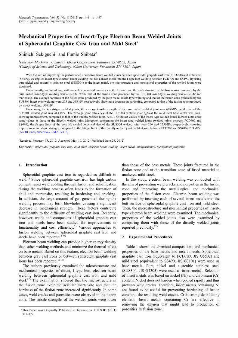
Welding tool was a 6 kW high-voltage, high-vacuumelectron beam welding machine (all vacuum type). Immedi-ately before welding, the base metals were demagnetized, andthe butt surface was degreased with methyl ethyl ketone. Asshown in Fig. 1, electron beam welding was performed byinserting an insert metal into the I-type butt weld surfaces,and also with both ends of base metals being lightly heldwith fixtures. The dimensions of the base metals were18 © 200 © 200mm, while those of the insert metals were0.5 © 18 © 200mm.
Test specimens were joined with two-pass welds (down-ward penetration welding). Table 2 shows the weldingconditions. The welding conditions ensure that the shape offusion zone will be formed parallel bead18) and that beadwidth will be same both top and bottom. Accordingly,between pure Ni and SUS304 with a difference in thermalconductivity, the pure Ni insert-type welding requiredslightly more welding heat input than the SUS304 insert-type welding. (In this paper, the term “pure Ni welding”refers to use of pure Ni insert metal, and the term “SUS304welding” refers to use of SUS304 insert metal.)
The welding microstructure was microscopically observedby cutting the bead transversely, polishing the cut surface,and then etching the fusion zone surface with 10% aqueoussolution of chromic acid and the treating surface of the heateffected zone and base metals with 4% nital. Furthermore, thechemical analysis of the fusion zone was conducted.
For material tests, a Micro Vickers hardness tester (with aHVof 0.3) was used to measure the hardness at 0.1mm pitchin the weld cross section. Tensile tests (using the testspecimens No. 4, defined by JIS Z2201 “Test pieces fortensile test for metallic materials”), Charpy impact tests(Non-notch, 10 © 10 © 55mm, at test temperatures of 77 to373K), and rotary bending fatigue tests (at a rotational speed
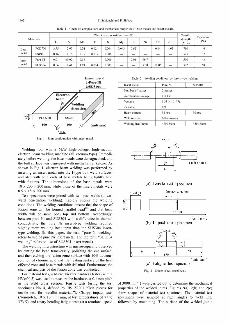
of 3000min¹1) were carried out to determine the mechanicalproperties of the welded joints. Figures 2(a), 2(b) and 2(c)show shapes of material test specimen. The material testspecimens were sampled at right angles to weld line,followed by machining. The surface of the welded joints
Table 1 Chemical compositions and mechanical properties of base metals and insert metals.
MaterialsChemical composition (mass%) Tensile
strength(MPa)
Elongation(%)C Si Mn P S Mg Cu Ni Cr C.E.
Basemetal
FCD700 3.75 2.67 0.24 0.02 0.004 0.043 0.62 ® 0.04 4.65 790 6
SS490 0.16 0.16 0.95 0.017 0.006 ® ® ® ® ® 528 37
Insertmetal
Pure Ni 0.01 <0.001 0.18 ® 0.001 ® 0.01 99.7 ® ® 500 43
SUS304 0.06 0.41 1.19 0.034 0.009 ® ® 8.30 18.05 ® 592 69
200
FCD700
Electronbeam
100 100
18
(unit:mm)
Insert metal1)Pure Ni2)SUS304
SS490
Weldingdirection
0.5
Fig. 1 Joint configuration with insert metal.
Table 2 Welding conditions by insert-type welding.
Insert metal Pure Ni SUS304
Number of passes 2 passes
Acceleration voltage 150 kV
Vacuum 1.33 © 10¹2 Pa
ab value 0.9
Beam current 32mA 30mA
Welding speed 600mm/min
Welding heat input 4800 J/cm 4500 J/cm
Fig. 2 Shape of test specimens.
S. Sekiguchi and F. Shibata1462
fracture in tension and impact was observed with a scanningelectron microscope (SEM) and surface analysis with EPMA.
3. Results and Discussion
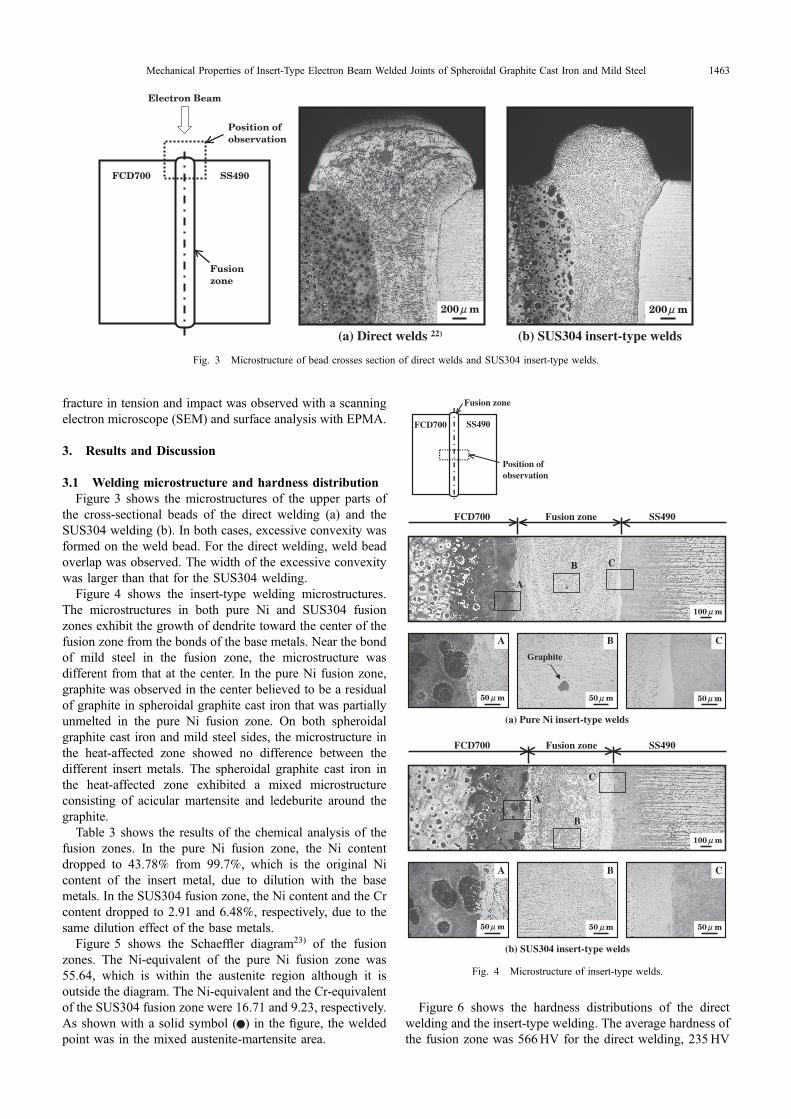
3.1 Welding microstructure and hardness distributionFigure 3 shows the microstructures of the upper parts of
the cross-sectional beads of the direct welding (a) and theSUS304 welding (b). In both cases, excessive convexity wasformed on the weld bead. For the direct welding, weld beadoverlap was observed. The width of the excessive convexitywas larger than that for the SUS304 welding.
Figure 4 shows the insert-type welding microstructures.The microstructures in both pure Ni and SUS304 fusionzones exhibit the growth of dendrite toward the center of thefusion zone from the bonds of the base metals. Near the bondof mild steel in the fusion zone, the microstructure wasdifferent from that at the center. In the pure Ni fusion zone,graphite was observed in the center believed to be a residualof graphite in spheroidal graphite cast iron that was partiallyunmelted in the pure Ni fusion zone. On both spheroidalgraphite cast iron and mild steel sides, the microstructure inthe heat-affected zone showed no difference between thedifferent insert metals. The spheroidal graphite cast iron inthe heat-affected zone exhibited a mixed microstructureconsisting of acicular martensite and ledeburite around thegraphite.
Table 3 shows the results of the chemical analysis of thefusion zones. In the pure Ni fusion zone, the Ni contentdropped to 43.78% from 99.7%, which is the original Nicontent of the insert metal, due to dilution with the basemetals. In the SUS304 fusion zone, the Ni content and the Crcontent dropped to 2.91 and 6.48%, respectively, due to thesame dilution effect of the base metals.
Figure 5 shows the Schaeffler diagram23) of the fusionzones. The Ni-equivalent of the pure Ni fusion zone was55.64, which is within the austenite region although it isoutside the diagram. The Ni-equivalent and the Cr-equivalentof the SUS304 fusion zone were 16.71 and 9.23, respectively.As shown with a solid symbol ( ) in the figure, the weldedpoint was in the mixed austenite-martensite area.
Figure 6 shows the hardness distributions of the directwelding and the insert-type welding. The average hardness ofthe fusion zone was 566HV for the direct welding, 235HV
FCD700
Fusionzone
SS490
Position ofobservation
Electron Beam
(a) Direct welds 22)
200µ m
(b) SUS304 insert-type welds
200µ m
Fig. 3 Microstructure of bead crosses section of direct welds and SUS304 insert-type welds.
SS490FCD700 Fusion zone
(a) Pure Ni insert-type welds
100 µ m
A
B C
A B C
50µ m50 µ m50 µ m
Graphite
(b) SUS304 insert-type welds
SS490FCD700 Fusion zone
A B C
A
B
C
100 µ m
50µ m50 µ m50µ m
FCD700
Fusion zone
SS490
Position ofobservation
Fig. 4 Microstructure of insert-type welds.
Mechanical Properties of Insert-Type Electron Beam Welded Joints of Spheroidal Graphite Cast Iron and Mild Steel 1463
for the pure Ni welding, and 393HV for the SUS304 weldingindicating that the hardness of the fusion zone for the pure Niwelding and the SUS304 welding was lower than that of thedirect welding. Particularly, the hardness in the fusion zonefor the pure Ni welding was almost equal to that of both basemetals. Possibly, this result occurred because the micro-structure in the pure Ni welding fusion zone formedaustenite, while the microstructure in the direct weldingfusion zone formed acicular martensite. In all cases, themaximum hardness of the fusion zone was observed withinabout 0.2mm from the bond of mild steel toward the fusionzone; the value was 820HV for the direct welding, 323HVfor the pure Ni welding, and 559HV for the SUS304welding. While the difference in hardness between the fusionzone and the mild steel in the heat-affected zone was large forthe direct welding, it was small for the pure Ni welding and
the SUS304 welding due to the use of the insert metals. Onthe other hand, a significant increase in hardness wasapparent in the spheroidal graphite cast iron in the heat-affected zone; no effect of the insert metals was observed.Potentially, the microstructure of the spheroidal graphite castiron in the heat-affected zone was the same for all weldingtypes.
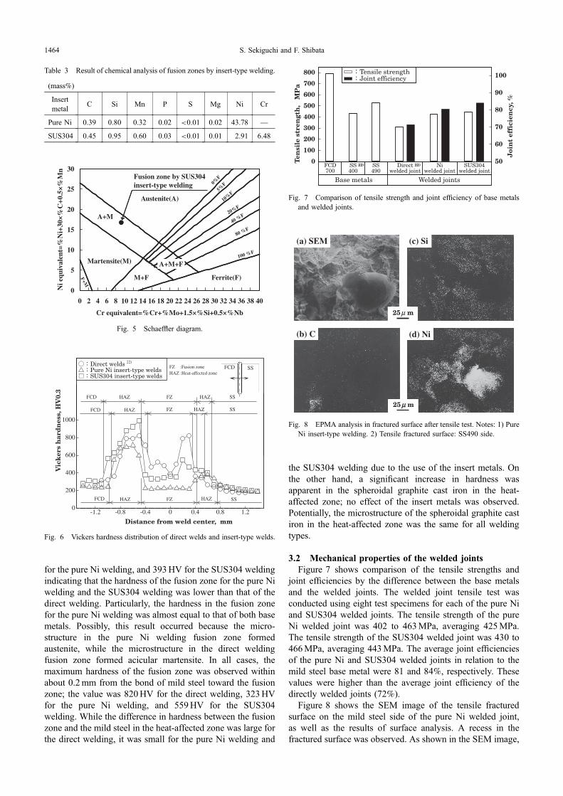
3.2 Mechanical properties of the welded jointsFigure 7 shows comparison of the tensile strengths and
joint efficiencies by the difference between the base metalsand the welded joints. The welded joint tensile test wasconducted using eight test specimens for each of the pure Niand SUS304 welded joints. The tensile strength of the pureNi welded joint was 402 to 463MPa, averaging 425MPa.The tensile strength of the SUS304 welded joint was 430 to466MPa, averaging 443MPa. The average joint efficienciesof the pure Ni and SUS304 welded joints in relation to themild steel base metal were 81 and 84%, respectively. Thesevalues were higher than the average joint efficiency of thedirectly welded joints (72%).
Figure 8 shows the SEM image of the tensile fracturedsurface on the mild steel side of the pure Ni welded joint,as well as the results of surface analysis. A recess in thefractured surface was observed. As shown in the SEM image,
Table 3 Result of chemical analysis of fusion zones by insert-type welding.
(mass%)
Insertmetal
C Si Mn P S Mg Ni Cr
Pure Ni 0.39 0.80 0.32 0.02 <0.01 0.02 43.78 ®
SUS304 0.45 0.95 0.60 0.03 <0.01 0.01 2.91 6.48
0
5
10
15
20
25
30
0 2 4 6 8 10 12 14 16 18 20 22 24 26 28 30 32 34 36 38 40
Cr equivalent=%Cr+%Mo+1.5×%Si+0.5×%Nb
Ni e
quiv
alen
t=%
Ni+
30×%
C+0
.5×%
Mn
Austenite(A)
A+M
Martensite(M)
M+F
A+M+F
Ferrite(F)F+M
0%F
5%F
10%F
20%F
40 %F
80 %F
100 %F
Fusion zone by SUS304 insert-type welding
Fig. 5 Schaeffler diagram.
-1.2 -0.8 -0.4 0 0.4 0.8 1.20
200
400
600
800
1000
Distance from weld center, mm
FCD SS
Vic
ker
s h
ard
nes
s, H
V0.
3
Direct welds 22)
Pure Ni insert-type weldsSUS304 insert-type welds
FZFCD SSHAZ
FZHAZ SSDCF HAZ
FZHAZFCD SSHAZ
HAZ
FZ :Fusion zoneHAZ :Heat-affected zone
Fig. 6 Vickers hardness distribution of direct welds and insert-type welds.
0
100
200
300
400
500
600
700
800
50
60
70
80
90
100
Ten
sile
str
engt
h,
MP
a
Niwelded joint
Direct 22)
welded jointSS490
FCD700
SS 22)
400
Welded jointsBase metals
Tensile strengthJoint efficiency
SUS304welded joint
Joi
nt
effi
cien
cy, %
Fig. 7 Comparison of tensile strength and joint efficiency of base metalsand welded joints.
(a) SEM
25µµ m
(b) C
(c) Si
(d) Ni
25µ m
Fig. 8 EPMA analysis in fractured surface after tensile test. Notes: 1) PureNi insert-type welding. 2) Tensile fractured surface: SS490 side.
S. Sekiguchi and F. Shibata1464
the content of carbon (C) was high in some areas, suggestingthe presence of graphite. Contrary to C, silicon (Si) wasdistributed across the observed surface. Ni also was mostlydistributed, but its content was high in some areas. Si wasabsent in the areas with high Ni content. The presence ofspheroidal graphite and the distributions of Si and Ni suggestthat the tensile fracture occurred at the bond of spheroidalgraphite cast iron.
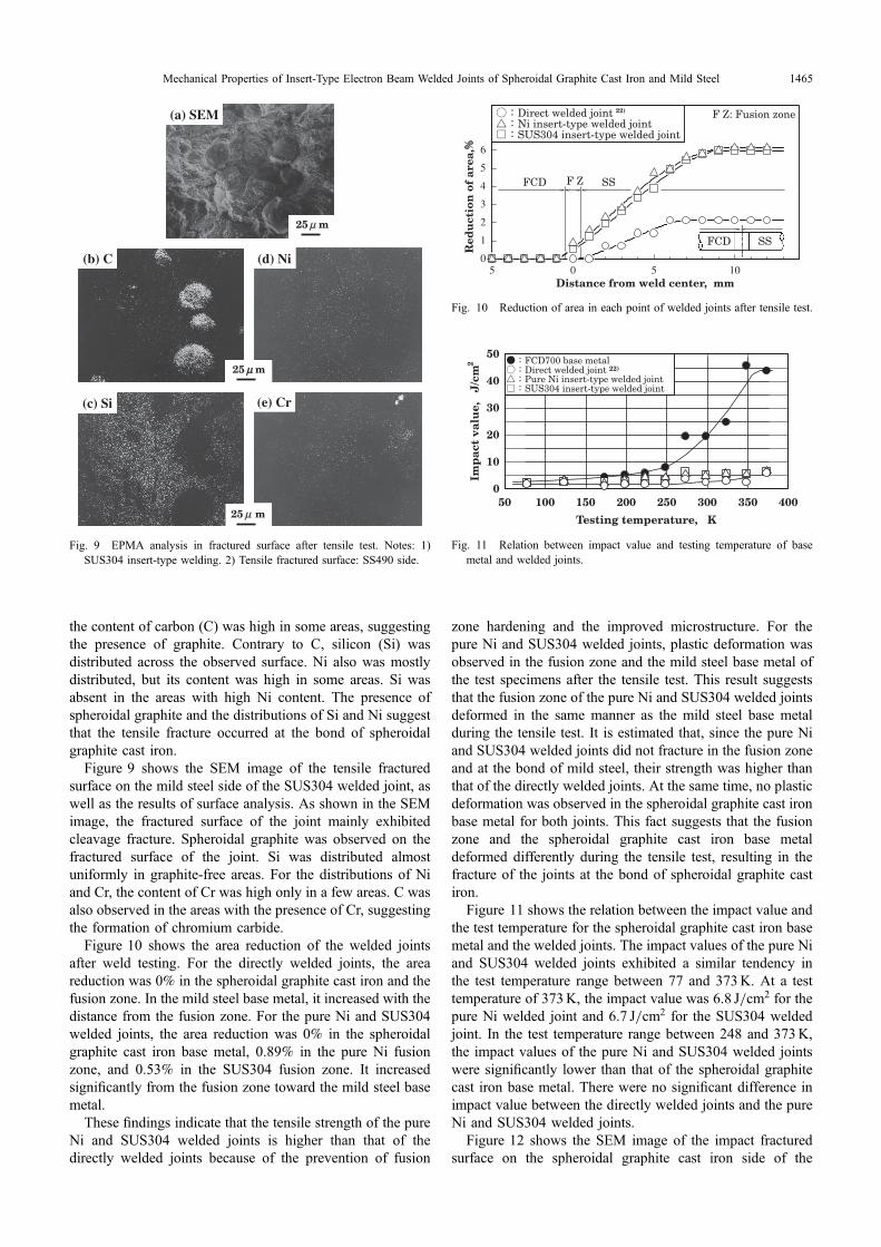
Figure 9 shows the SEM image of the tensile fracturedsurface on the mild steel side of the SUS304 welded joint, aswell as the results of surface analysis. As shown in the SEMimage, the fractured surface of the joint mainly exhibitedcleavage fracture. Spheroidal graphite was observed on thefractured surface of the joint. Si was distributed almostuniformly in graphite-free areas. For the distributions of Niand Cr, the content of Cr was high only in a few areas. C wasalso observed in the areas with the presence of Cr, suggestingthe formation of chromium carbide.
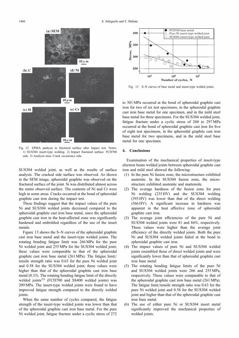
Figure 10 shows the area reduction of the welded jointsafter weld testing. For the directly welded joints, the areareduction was 0% in the spheroidal graphite cast iron and thefusion zone. In the mild steel base metal, it increased with thedistance from the fusion zone. For the pure Ni and SUS304welded joints, the area reduction was 0% in the spheroidalgraphite cast iron base metal, 0.89% in the pure Ni fusionzone, and 0.53% in the SUS304 fusion zone. It increasedsignificantly from the fusion zone toward the mild steel basemetal.
These findings indicate that the tensile strength of the pureNi and SUS304 welded joints is higher than that of thedirectly welded joints because of the prevention of fusion
zone hardening and the improved microstructure. For thepure Ni and SUS304 welded joints, plastic deformation wasobserved in the fusion zone and the mild steel base metal ofthe test specimens after the tensile test. This result suggeststhat the fusion zone of the pure Ni and SUS304 welded jointsdeformed in the same manner as the mild steel base metalduring the tensile test. It is estimated that, since the pure Niand SUS304 welded joints did not fracture in the fusion zoneand at the bond of mild steel, their strength was higher thanthat of the directly welded joints. At the same time, no plasticdeformation was observed in the spheroidal graphite cast ironbase metal for both joints. This fact suggests that the fusionzone and the spheroidal graphite cast iron base metaldeformed differently during the tensile test, resulting in thefracture of the joints at the bond of spheroidal graphite castiron.
Figure 11 shows the relation between the impact value andthe test temperature for the spheroidal graphite cast iron basemetal and the welded joints. The impact values of the pure Niand SUS304 welded joints exhibited a similar tendency inthe test temperature range between 77 and 373K. At a testtemperature of 373K, the impact value was 6.8 J/cm2 for thepure Ni welded joint and 6.7 J/cm2 for the SUS304 weldedjoint. In the test temperature range between 248 and 373K,the impact values of the pure Ni and SUS304 welded jointswere significantly lower than that of the spheroidal graphitecast iron base metal. There were no significant difference inimpact value between the directly welded joints and the pureNi and SUS304 welded joints.
Figure 12 shows the SEM image of the impact fracturedsurface on the spheroidal graphite cast iron side of the
(a) SEM
(b) C
(c) Si
(d) Ni
(e) Cr
25 µµ m
25 µ m
25 µ m
Fig. 9 EPMA analysis in fractured surface after tensile test. Notes: 1)SUS304 insert-type welding. 2) Tensile fractured surface: SS490 side.
5 0 5 100
1
2
3
4
5
6
Red
uct
ion
of
area
,
FCD F Z
F Z: Fusion zone
FCD
Direct welded jointNi insert-type welded jointSUS304 insert-type welded joint
SS
SS
Distance from weld center, mm
22)
Fig. 10 Reduction of area in each point of welded joints after tensile test.
50 100 150 200 250 300 350 4000
10
20
30
40
50
Testing temperature, K
Imp
act
valu
e,
J/c
m2 FCD700 base metal
Direct welded joint 22)
Pure Ni insert-type welded jointSUS304 insert-type welded joint
Fig. 11 Relation between impact value and testing temperature of basemetal and welded joints.
Mechanical Properties of Insert-Type Electron Beam Welded Joints of Spheroidal Graphite Cast Iron and Mild Steel 1465
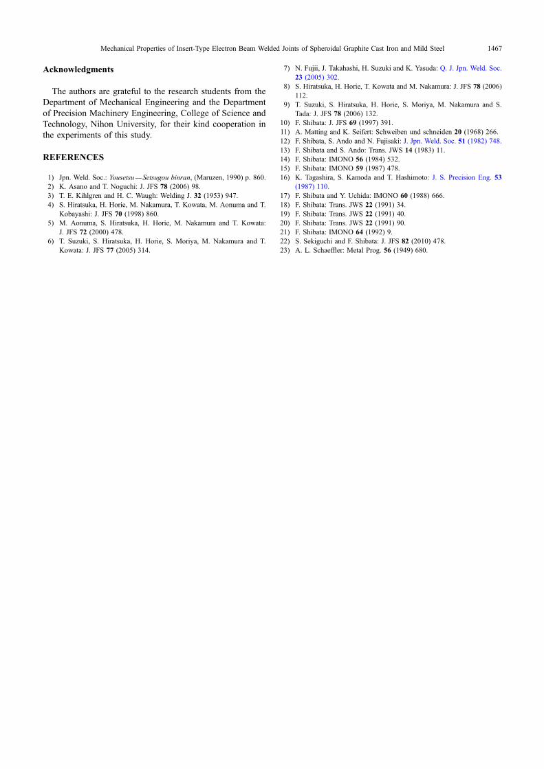
SUS304 welded joint, as well as the results of surfaceanalysis. The cracked side surface was observed. As shownin the SEM image, spheroidal graphite was observed on thefractured surface of the joint. Si was distributed almost acrossthe entire observed surface. The contents of Ni and Cr werehigh in some areas. Cracks occurred at the bond of spheroidalgraphite cast iron during the impact test.
These findings suggest that the impact values of the pureNi and SUS304 welded joints decreased compared to thespheroidal graphite cast iron base metal, since the spheroidalgraphite cast iron in the heat-affected zone was significantlyhardened and embrittled regardless of the use of the insertmetals.
Figure 13 shows the SN curves of the spheroidal graphitecast iron base metal and the insert-type welded joints. Therotating bending fatigue limit was 266MPa for the pureNi welded joint and 255MPa for the SUS304 welded joint;these values were comparable to that of the spheroidalgraphite cast iron base metal (261MPa). The fatigue limit/tensile strength ratio was 0.63 for the pure Ni welded jointand 0.58 for the SUS304 welded joint; these values werehigher than that of the spheroidal graphite cast iron basemetal (0.33). The rotating bending fatigue limit of the directlywelded joints22) (FCD700 and SS400 welded joints) was209MPa. The insert-type welded joints were found to haveimproved fatigue strength compared to the directly weldedjoints.
When the same number of cycles compared, the fatiguestrength of the insert-type welded joints was lower than thatof the spheroidal graphite cast iron base metal. For the pureNi welded joint, fatigue fracture under a cyclic stress of 272
to 301MPa occurred at the bond of spheroidal graphite castiron for two of six test specimens, in the spheroidal graphitecast iron base metal for one specimen, and in the mild steelbase metal for three specimens. For the SUS304 welded joint,fatigue fracture under a cyclic stress of 260 to 297MPaoccurred at the bond of spheroidal graphite cast iron for fiveof eight test specimens, in the spheroidal graphite cast ironbase metal for two specimens, and in the mild steel basemetal for one specimen.
4. Conclusions
Examination of the mechanical properties of insert-typeelectron beam welded joints between spheroidal graphite castiron and mild steel showed the following:(1) In the pure Ni fusion zone, the microstructure exhibited
austenite. In the SUS304 fusion zone, the micro-structure exhibited austenite and martensite.
(2) The average hardness of the fusion zone for pureNi welding (235HV) and the SUS304 welding(393HV) was lower than that of the direct welding(566HV). A significant increase in hardness wasapparent in the heat affective zone of spheroidalgraphite cast iron.
(3) The average joint efficiencies of the pure Ni andSUS304 welded joints were 81 and 84%, respectively.These values were higher than the average jointefficiency of the directly welded joints. Both the pureNi and SUS304 welded joints failed at the bond tospheroidal graphite cast iron.
(4) The impact values of pure Ni and SUS304 weldedjoints resembled those of direct welded joints and weresignificantly lower than that of spheroidal graphite castiron base metal.
(5) The rotating bending fatigue limits of the pure Niand SUS304 welded joints were 266 and 255MPa,respectively. These values were comparable to that ofthe spheroidal graphite cast iron base metal (261MPa).The fatigue limit/tensile strength ratio was 0.63 for thepure Ni welded joint and 0.58 for the SUS304 weldedjoint and higher than that of the spheroidal graphite castiron base metal.
(6) The use of either pure Ni or SUS304 insert metalsignificantly improved the mechanical properties ofwelded joints.
(a) SEM
(b) C
(c) Si
(d) Ni
(e) Cr
25µµ m
25 µ m
25µ m
Fig. 12 EPMA analysis in fractured surface after impact test. Notes:1) SUS304 insert-type welding. 2) Impact fractured surface: FCD700side. 3) Analysis area: Crack occurrence side.
105 106 107
250
300
350
400
Number of cycles, N
Str
ess,
M
Pa
~~
: Pure Ni insert-type welded joint: SUS304 insert-type welded joint
: FCD700 base metal
Fig. 13 SN curves of base metal and insert-type welded joints.
S. Sekiguchi and F. Shibata1466
Acknowledgments
The authors are grateful to the research students from theDepartment of Mechanical Engineering and the Departmentof Precision Machinery Engineering, College of Science andTechnology, Nihon University, for their kind cooperation inthe experiments of this study.
REFERENCES
1) Jpn. Weld. Soc.: Yousetsu® Setsugou binran, (Maruzen, 1990) p. 860.2) K. Asano and T. Noguchi: J. JFS 78 (2006) 98.3) T. E. Kihlgren and H. C. Waugh: Welding J. 32 (1953) 947.4) S. Hiratsuka, H. Horie, M. Nakamura, T. Kowata, M. Aonuma and T.
Kobayashi: J. JFS 70 (1998) 860.5) M. Aonuma, S. Hiratsuka, H. Horie, M. Nakamura and T. Kowata:
J. JFS 72 (2000) 478.6) T. Suzuki, S. Hiratsuka, H. Horie, S. Moriya, M. Nakamura and T.
Kowata: J. JFS 77 (2005) 314.
7) N. Fujii, J. Takahashi, H. Suzuki and K. Yasuda: Q. J. Jpn. Weld. Soc.23 (2005) 302.
8) S. Hiratsuka, H. Horie, T. Kowata and M. Nakamura: J. JFS 78 (2006)112.
9) T. Suzuki, S. Hiratsuka, H. Horie, S. Moriya, M. Nakamura and S.Tada: J. JFS 78 (2006) 132.
10) F. Shibata: J. JFS 69 (1997) 391.11) A. Matting and K. Seifert: Schweiben und schneiden 20 (1968) 266.12) F. Shibata, S. Ando and N. Fujisaki: J. Jpn. Weld. Soc. 51 (1982) 748.13) F. Shibata and S. Ando: Trans. JWS 14 (1983) 11.14) F. Shibata: IMONO 56 (1984) 532.15) F. Shibata: IMONO 59 (1987) 478.16) K. Tagashira, S. Kamoda and T. Hashimoto: J. S. Precision Eng. 53
(1987) 110.17) F. Shibata and Y. Uchida: IMONO 60 (1988) 666.18) F. Shibata: Trans. JWS 22 (1991) 34.19) F. Shibata: Trans. JWS 22 (1991) 40.20) F. Shibata: Trans. JWS 22 (1991) 90.21) F. Shibata: IMONO 64 (1992) 9.22) S. Sekiguchi and F. Shibata: J. JFS 82 (2010) 478.23) A. L. Schaeffler: Metal Prog. 56 (1949) 680.
Mechanical Properties of Insert-Type Electron Beam Welded Joints of Spheroidal Graphite Cast Iron and Mild Steel 1467