mechanical project pump station
DESCRIPTION
collector pump stationTRANSCRIPT

WATER SUPPLY AND SANITATION ADRIATIC COAST III – HERCEG NOVI
TENDER DOCUMENTS
VOLUME III: Technical SpecificationsSection 3 3: Specifications Mechanical WorksSection 3.3: Specifications Mechanical Works
April 2011
L E A D I N G P A R T N E RESSEN, GERMANY ERKRATH, GERMANY

Project title: Water Supply and Sanitation Adriatic Coast III – Herceg Novi Project number: BMZ ID 2006 66 198 Project number Vodacom: RB_HN_2009
1
WATER SUPPLY AND SANITATION ADRIATIC COAST III – HERCEG NOVI
TENDER DOCUMENTS
Volume 3 – Technical Specifications
Section 3.3 Specifications Mechanical Works
GENERAL SPECIFICATIONS MECHANICAL ENGINEERING WORKS

WATER SUPPLY AND SANITATION ADRIATIC COAST III – HERCEG NOVI
VOLUME III – TECHNICAL SPECIFICATION
Project title: Water Supply and Sanitation Adriatic Coast III – Herceg Novi Project number: BMZ ID 2006 66 198 Project number Vodacom: RB_HN_2009
2
TABLE OF CONTENTS
1 General specifications Mechancial works 7 1.1 CONTRACTOR’S OBLIGATIONS 7 1.2 DEFINITION OF SUPPLY OF COMPLETE EQUIPMENT 7 1.3 STANDARDS 8 1.4 QUALITY STANDARD 9 1.5 EQUIPMENT GUARANTEE 9 1.6 PATENT 9 1.7 WELDING WORKS 10 1.8 CORROSION PROTECTION 11 1.8.1 General 11 1.8.2 Applicable Standards 12 1.8.3 Shotblasting 13 1.8.4 Galvanizing 13 1.8.5 Applicable Corrosion Protection Systems 13 1.8.6 Application of coating for plant equipment 13 1.8.7 Colour Design 13 1.8.8 Calculation 14 1.9 SPARE PARTS 14 1.10 MINIMUM SPARES REQUIREMENT 14 1.11 TEEKEYS AND KEYS 15 1.12 REQUIREMENT OF INSTRUCTION MANUALS 16 1.12.1 Operation and Maintenance Manuals 17 1.12.2 As built Drawings 18 1.13 GENERAL SPECIFICATIONS ON EQUIPMENT 19 1.13.1 Workmanship and Material 19 1.13.2 Safety Guard 19 1.13.3 Foundation and Bedplate of Equipment 19 1.13.4 Fasteners 19 1.13.5 Special Tools and Accessories 20 1.13.6 Data Plate 20 1.13.7 Lubrication 20 1.13.8 Coupling 20 1.13.9 Equipment Protection 20 1.13.10 Anti-Corrosion of Materials 21 1.13.11 Electric Motor 21

WATER SUPPLY AND SANITATION ADRIATIC COAST III – HERCEG NOVI
VOLUME III – TECHNICAL SPECIFICATION
Project title: Water Supply and Sanitation Adriatic Coast III – Herceg Novi Project number: BMZ ID 2006 66 198 Project number Vodacom: RB_HN_2009
3
1.13.12 Explosion Protection 24 1.13.13 Noise Protection 25 1.13.14 Supplementary Principles for Mechanical Design and Measurement 25 1.13.15 Labeling of Equipment 25 1.14 PIPING AND FITTINGS 26 1.14.1 General 26 1.14.2 Piping 26 1.14.3 Dismantling Pieces, Lockable 26 1.14.4 Dismantling Pieces, Non-lockable 26 1.14.5 Reducer 28 1.14.6 Flange Connections 28 1.14.7 Flush Appliances 29 1.14.8 Vent Pipes 29 1.14.9 Measuring Instruments 29 1.14.10 Pipe hangers 29 1.14.11 Installation of Piping 30 1.14.12 Flushing and Pressure Test 30 1.14.13 Stainless Steel Pipes and Fittings 30 1.14.14 Painting and Marking of Equipment 31 1.15 DETAILED SPECIFICATIONS MECHANICAL EQUIPMENT 32 1.15.1 Screens 32 1.15.2 Conveyers 34 1.15.3 Presses and Classifiers 36 1.15.4 Pumps 37 1.15.5 Valves, Penstocks and Actuators 42 1.15.6 Fans 74 1.15.7 Stand-by emergency power plant 75 1.15.8 Lifting equipment 92
2 Particular specifications MechanIcal works 94 2.1 MECHANICAL WORKS PUMPING STATION IGALO 95 2.1.1 Pumps 95 2.1.2 Pipework 95 2.1.3 Gates 96 2.1.4 Manual coarse bar screen 96 2.1.5 Emergency Diesel Generator 97 2.1.6 Personal Training 97 2.1.7 Documentation 97 2.2 MECHANICAL WORKS PUMPING STATION CENTAR 98

WATER SUPPLY AND SANITATION ADRIATIC COAST III – HERCEG NOVI
VOLUME III – TECHNICAL SPECIFICATION
Project title: Water Supply and Sanitation Adriatic Coast III – Herceg Novi Project number: BMZ ID 2006 66 198 Project number Vodacom: RB_HN_2009
4
2.2.1 Pumps 98 2.2.2 Pipework 98 2.2.3 Gates 99 2.2.4 Manual coarse bar screen 99 2.2.5 Emergency Diesel Generator 100 2.2.6 Personal Training 100 2.2.7 Documentation 101 2.3 MECHANICAL WORKS PUMPING STATION FORTE MARE 101 2.3.1 Pumps 101 2.3.2 Pipework 102 2.3.3 Gates 102 2.3.4 Manual coarse bar screen 104 2.3.5 Emergency Diesel Generator 104 2.3.6 Personal Training 105 2.3.7 Documentation 105 2.4 MECHANICAL WORKS PUMPING STATION SAVINA 105 2.4.1 Pumps 105 2.4.2 Pipework 106 2.4.3 Gates 107 2.4.4 Manual coarse bar screen 107 2.4.5 Emergency Diesel Generator 107 2.4.6 Personal Training 108 2.4.7 Documentation 108 2.5 MECHANICAL WORKS PUMPING STATION MELIJINE ROUNDABOUT 109 2.5.1 Pumps 109 2.5.2 Pipework 109 2.5.3 Coarse Screen and mobile waste container 110 2.5.4 Emergency Diesel Generator 111 2.5.5 Measurement and Instrumentation 112 2.5.6 Pressure Surge Protection 112 2.5.7 Ventilation machinery room 112 2.5.8 Air pollution control plant 113 2.5.9 Penstocks 113 2.5.10 Lifting Equipment 114 2.5.11 Equipment for the Potable Water System 114 2.5.12 Personal Training 114 2.5.13 Documentation 115 2.6 MECHANICAL WORKS PUMPING STATION BIJELA SHIPYARD 115
WATER SUPPLY AND SANITATION ADRIATIC COAST III – HERCEG NOVI
VOLUME III – TECHNICAL SPECIFICATION
Project title: Water Supply and Sanitation Adriatic Coast III – Herceg Novi Project number: BMZ ID 2006 66 198 Project number Vodacom: RB_HN_2009
5
2.6.1 Pumps 115 2.6.2 Pipework 116 2.6.3 Gates 117 2.6.4 Manual coarse bar screen 117 2.6.5 Emergency Diesel Generator 117 2.6.6 Personal Training 118 2.6.7 Documentation 118 2.7 MECHANICAL WORKS PUMPING STATION BIJELA WEST 119 2.7.1 Pumps 119 2.7.2 Pipework 119 2.7.3 Gates 120 2.7.4 Manual coarse bar screen 120 2.7.5 Emergency Diesel Generator 121 2.7.6 Personal Training 121 2.7.7 Documentation 122 2.8 MECHANICAL WORKS PUMPING STATION DENOVICI 122 2.8.1 Pumps 122 2.8.2 Pipework 123 2.8.3 Gates 123 2.8.4 Manual coarse bar screen 124 2.8.5 Emergency Diesel Generator 124 2.8.6 Personal Training 125 2.8.7 Documentation 125 2.9 MECHANICAL WORKS PUMPING STATION KUMBOR 125 2.9.1 Pumps 125 2.9.2 Pipework 126 2.9.3 Gates 127 2.9.4 Manual coarse bar screen 127 2.9.5 Emergency Diesel Generator 129 2.9.6 Personal Training 129 2.9.7 Documentation 129 2.10 MECHANICAL WORKS PUMPING STATION KUMBOR NORTH 130 2.10.1 Pumps 130 2.10.2 Pipework 130 2.10.3 Gates 131 2.10.4 Manual coarse bar screen 132 2.10.5 Emergency Diesel Generator 132 2.10.6 Personal Training 132

WATER SUPPLY AND SANITATION ADRIATIC COAST III – HERCEG NOVI
VOLUME III – TECHNICAL SPECIFICATION
Project title: Water Supply and Sanitation Adriatic Coast III – Herceg Novi Project number: BMZ ID 2006 66 198 Project number Vodacom: RB_HN_2009
6
2.10.7 Documentation 133 2.11 MECHANICAL WORKS PUMPING STATION ZMIJICE 133 2.11.1 Pumps 133 2.11.2 Pipework 135 2.11.3 Gates 136 2.11.4 Manual coarse bar screen 136 2.11.5 Emergency Diesel Generator 136 2.11.6 Personal Training 137 2.11.7 Documentation 137 2.12 MECHANICAL WORKS PUMPING STATION ZELENIKA 138 2.12.1 Pumps 138 2.12.2 Pipework 138 2.12.3 Gates 139 2.12.4 Manual coarse bar screen 139 2.12.5 Emergency Diesel Generator 140 2.12.6 Personal Training 140 2.12.7 Documentation 141 2.13 MECHANICAL WORKS PUMPING STATION MELJINE OLD 141 2.13.1 Pumps 141 2.13.2 Pipework 142 2.13.3 Emergency Diesel Generator 142 2.13.4 Personal Training 143 2.13.5 Documentation 143

WATER SUPPLY AND SANITATION ADRIATIC COAST III – HERCEG NOVI
VOLUME III – TECHNICAL SPECIFICATION
Project title: Water Supply and Sanitation Adriatic Coast III – Herceg Novi Project number: BMZ ID 2006 66 198 Project number Vodacom: RB_HN_2009
7
1 GENERAL SPECIFICATIONS MECHANCIAL WORKS
1.1 CONTRACTOR’S OBLIGATIONS
The Contractor shall carry out all the contents within the scope of his work, includ-ing execution design, supply to site, installation of the mechanical and electrical equipment, testing run and commissioning, and training of the Employer’s techni-cal and operation personnel. The Tenderer shall carry out all the necessary calculations, contingent further execution design work and filling in the Schedules required for the completion of his bid. In the process of preparing his offer, the Tenderer must verify the Con-sultant’s design calculations. In the case of any ambiguity, the Tenderer has to in-form the Engineer immediately and ask for clarification. The Tenderer shall submit detailed description and performance curves of the proposed equipment in order to facilitate the evaluation of the bid by the Consult-ant. The Tenderer must provide Process and Instrumentation Diagrams (P & I Diagram) for the Waste Water Pumping Stations according to the related require-ment. If changes to the Consultant’s design are proposed or required due to the equip-ment and machinery offered, the Tenderer has to provide his own conceptual de-sign drawings with the proposed changes clearly marked and documented. The Tenderer must provide all necessary Tendering Documents according the Specification (report, design, adjustment to the design of the Consultant, if any, drawings, etc.), which clearly show the contents and complementary requirements of the Works. If certain mechanical equipment has not been included in the scope of supply in the Contract, but it is required by the normal function of the design, the Contractor shall provide the Employer with necessary documents to ensure the compatibility of the equipment purchased, and that which is provided by the Contractor.
All the expenses of the above work shall be contained in certain items in the Schedule of Prices.
1.2 DEFINITION OF SUPPLY OF COMPLETE EQUIPMENT
Where used in this specification, the term ‘Supply’ shall mean all of the execution designs, drawings, documentation for and the manufacturing, packing, despatch, transport, installation, testing, commissioning of the respective items of the com-plete equipment and the complete process systems specified and/or tendered for installation at the site(s) by the contractor according to the contractor’s instruc-tions and under his supervision.

WATER SUPPLY AND SANITATION ADRIATIC COAST III – HERCEG NOVI
VOLUME III – TECHNICAL SPECIFICATION
Project title: Water Supply and Sanitation Adriatic Coast III – Herceg Novi Project number: BMZ ID 2006 66 198 Project number Vodacom: RB_HN_2009
8
The term ‘Supply’ shall include but not be limited to: 1. Complete equipment of pumping stations
• mechanical and all other equipment and accessories within process units and ancillary structures;
• equipment including hoists, conveyors, valve operating systems and
scour systems and waste disposal • pipework, penstocks, gates, fittings and all accessories.
2. Miscellaneous
• pipework, jointing materials including connectors, gaskets, bolts, nuts and washers;
• identification markings, tabs, tags and the like; • fasteners, clips, stands, trays and hangers and all other auxiliary materi-
als of any description. 3. Installation work of the equipment and machines delivered
• Installation of equipment and machines provided;
4. Commissioning
• test run of all mechanical, electrical equipment and on commissioning of
the plant 5. Maintenance & operating instructions & spare parts lists for all items of
plant delivered:
• Parts and tools for routine maintenance; • Maintenance & operating Instruction manuals; • Spare parts.
1.3 STANDARDS
The Mechanical Works shall comply as a minimum with International Standards ISO, EN or DIN Standards* named as I.S., with the respective Codes of Practice and Standards generally used for water supply and waste water facilities in for-eign countries, adapted to the local conditions, shall be used as an alternative subject to written approval by the Engineer. For example: EN: European Standard
WATER SUPPLY AND SANITATION ADRIATIC COAST III – HERCEG NOVI
VOLUME III – TECHNICAL SPECIFICATION
Project title: Water Supply and Sanitation Adriatic Coast III – Herceg Novi Project number: BMZ ID 2006 66 198 Project number Vodacom: RB_HN_2009
9
DIN: German Industrial Standard VDE: Standards of the German Electrical engineers’ Society DWA: Standards of the German Association for the Water, Wastewater
and Waste DVGW: Standards of the German Society for Gas & Water Technology UVV: German Regulation for Accident Prevention GUV: Standards of German Judicial Ministry Accident Prevention Socie-
ty IEC: International Electrical Commission ISO: International Organization for Standardization SI: International System of Units
1.4 QUALITY STANDARD
When a certain piece of equipment is planned to be applied, the product of a cer-tain manufacturer, that manufacturer must be clearly marked. The purpose is to set up a quality standard, structure type and acceptable reference. Generally, a definite manufacturer for the respective item of plant shall be given in the Sche-dule of Particulars. The term of “or equal” for manufacturer shall not be applied. All the equipment and materials provided by the Contractor shall be new, modern, of good quality, faultless, with long service span and low maintenance.
1.5 EQUIPMENT GUARANTEE
The Contractor must ensure the Guarantee period of 2 years commencing from the date of successful take-over of the Pumping Stations. During the guarantee period, the Contractor shall maintain the equipment and carry out at least two overall inspections. During the guarantee period, in case of failure of any equip-ment or poor manufacturing, the Contractor shall be responsible for repairing and recovering smooth operation without delay, once he has been informed. If the Contractor fails to recover operation within 14 days, the Employer reserves the right to dispose by himself. The expenses shall be compensated by the Contractor with no rejection. The Employer reserves the right to reject the equipment or components found to be defect or not conforming to the Contract requirements. The equipment or com-ponents shall be repaired or replaced by the Contractor. The employer shall not afford any additional expenses thereof.
1.6 PATENT
The Contractor shall be responsible for all the patent charges and certificate fees on the equipment and process specified in the Contract and shall protect the Em-ployer from any damage. All appeals caused by certificate fees, document and patent infringement, or other law arbitration, lawsuit and expenses caused by the application of equipment and process shall have nothing to do with the Employer.

WATER SUPPLY AND SANITATION ADRIATIC COAST III – HERCEG NOVI
VOLUME III – TECHNICAL SPECIFICATION
Project title: Water Supply and Sanitation Adriatic Coast III – Herceg Novi Project number: BMZ ID 2006 66 198 Project number Vodacom: RB_HN_2009
10
The payable expenses specified in the Contract shall be regarded as having in-cluded any patent fees, certificate fees and other expenses of the like.
1.7 WELDING WORKS
The following standards shall be applied for the welding operation during the manufacturing and installation of equipment: • DIN 1910-3: Welding; Welding of Plastics, Processes • DIN 1910-11: Welding; terms dependent on materials for metal weld-
ing • DIN 1910-100: Welding and allied processes - Vocabulary - Part 100:
Metal welding processes with additions to DIN EN 14610
• DIN EN 14610 Welding and allied processes - Definitions of metal welding processes; Trilingual version EN 14610
• DIN EN ISO 6520-1: Welding and allied processes - Classification of geo-metric imperfections in metallic materials - Part 1: Fu-sion welding (ISO 6520-1:2007)
• DIN EN ISO 6520-2: Welding and allied processes - Classification of geo-metric imperfections in metallic materials - Part 2: Welding with pressure (ISO 6520-2:2001)
• DIN EN 287-1: Qualification test of welders - Fusion welding - Part 1: Steels
• DIN EN ISO 9606-2: Qualification test of welders - Fusion welding - Part 2: Aluminium and aluminium alloys (ISO 9606-2:2004)
• DIN EN ISO 9606-3: Approval testing of welders - Fusion welding - Part 3: Copper and copper alloys (ISO 9606-3:1999)
• DIN EN ISO 3834-1: Quality requirements for fusion welding of metallic ma-terials - Part 1: Criteria for the selection of the appro-priate level of quality requirements (ISO 3834-1:2005)
• DIN EN ISO 3834-2: Quality requirements for fusion welding of metallic ma-terials - Part 2: Comprehensive quality requirements (ISO 3834-2:2005)
• DIN EN ISO 3834-3: Quality requirements for fusion welding for metallic materials - Part 3: Standard quality requirements (ISO 3834-3:2005)
• DIN EN ISO 3834-4: Quality requirements for fusion welding of metallic ma-terials - Part 4: Elementary quality requirements (ISO 3834-4:2005)
• DIN EN ISO 14731: Welding coordination - Tasks and responsibilities (ISO 14731:2006)
• DIN EN ISO 5817: Welding - Fusion-welded joints in steel, nickel, titanium and their alloys (beam welding excluded) - Quality le-vels for imperfections (ISO 5817:2003 + Cor. 1:2006)
• DIN EN ISO 14555: Welding - Arc stud welding of metallic materials (ISO 14555:2006)
• DIN EN ISO 13919-1: Welding - Electrons and laser beam welded joints; guidance on quality levels for imperfections - Part 1: Steel (ISO 13919-1:1996)

WATER SUPPLY AND SANITATION ADRIATIC COAST III – HERCEG NOVI
VOLUME III – TECHNICAL SPECIFICATION
Project title: Water Supply and Sanitation Adriatic Coast III – Herceg Novi Project number: BMZ ID 2006 66 198 Project number Vodacom: RB_HN_2009
11
• DIN EN ISO 13919-2: Welding - Electron and laser beam welded joints; Guidance on quality levels for imperfections - Part 2: Aluminium and its weldable alloys (ISO 13919-2:2001)
• DIN EN ISO 10042: Welding - Arc-welded joints in aluminium and its al-loys - Quality levels for imperfections (ISO 10042:2005)
DIN EN 25817 Arc-welded joints in steel; Guidance on quality levels for imperfections (ISO 5817:1992)
• DIN EN 462-1: Non-destructive testing; image quality of radiographs; part 1: image quality indicators (wire type); determina-tion of image quality values
• DIN EN 462-4: Non-destructive testing - Image quality of radio-graphs - Part 4: Experimental evaluation of image quality values and image quality tables
• DIN EN 462-3: Non-destructive testing - Image quality of radio-grammes - Part 3: Image quality classes for ferrous metals
• DIN EN 1435: Non-destructive testing of welds - Radiographic testing of welded joints
• DIN EN 12681: Founding - Radiographic examination • DIN EN 444: Non-destructive testing; general principles for the radi-
ographic examination of metallic materials using X-rays and gamma-rays
• DIN EN 1330-4: Non-destructive testing - Terminology - Part 4: Terms used in ultrasonic testing
Welding work on steel structures subjected to static and/or dynamic loads shall be carried out by welders holding a valid welding certificate according to DIN EN 287-1. On request, the certificates shall be submitted to the Employer. The valua-tion for welding seam execution shall be based on DIN EN ISO 5817, Categories B and C (category B for inside analysis; category C for outside analysis, for gas lines only category B will be accepted). Steel structure, in particular pipes, shall be shop-prefabricated as far as possible in order to minimize welding work on side. The Employers reserve the right to order at the Contractor’s expense the X-ray examination of up to a maximum of 10 % of all executed welding seams. In case more than 10 % of the examined welds fail the test, the Employer will order the X-ray examination of a further 30 % of all executed welding seams at the expense of the Contractor. If, again more than 10 % of the welds fail the tests, the Employer shall order the X-ray inspection of all welds. The Contractor shall bear all costs in-volved. The X-ray examination shall be conducted according to DIN EN 444, DIN EN 462 and DIN EN 1435. Test classification according to DIN EN ISO 5817.
1.8 CORROSION PROTECTION
1.8.1 General
The scope of work comprises the delivery and application of a complete and dur-able corrosion protection system. The expected life span is 60 months as a mini-
WATER SUPPLY AND SANITATION ADRIATIC COAST III – HERCEG NOVI
VOLUME III – TECHNICAL SPECIFICATION
Project title: Water Supply and Sanitation Adriatic Coast III – Herceg Novi Project number: BMZ ID 2006 66 198 Project number Vodacom: RB_HN_2009
12
mum. This work also includes all required scaffolding and all ancillary means re-quired for the execution of the work. Prior to the corrosion protection works, the installed hardware, non-ferrous and stainless steel components shall be protected against possible damages.
1.8.2 Applicable Standards
ISO 8504-2 Preparation of steel substrates before application of
paints and related products - Surface preparation me-thods - Part 2: Abrasive blast-cleaning
DIN 55 928-8 Protection of steel structures from corrosion by organic and metallic coatings; part 8: protection of supporting thin-walled building components from corrosion
DIN EN ISO 12944-1 Paints and varnishes - Corrosion protection of steel struc-tures by protective paint systems - Part 1: General intro-duction (ISO 12944-1:1998)
DIN EN ISO 12944-2 Paints and varnishes - Corrosion protection of steel struc-tures by protective paint systems - Part 2: Classification of environments (ISO 12944-2:1998)
DIN EN ISO 12944-3 Paints and varnishes - Corrosion protection of steel struc-tures by protective paint systems - Part 3: Design consid-erations (ISO 12944-3:1998)
DIN EN ISO 12944-4 Paints and varnishes - Corrosion protection of steel struc-tures by protective paint systems - Part 4: Types of sur-face and surface preparation (ISO 12944-4:1998)
DIN EN ISO 12944-5 Paints and varnishes - Corrosion protection of steel struc-tures by protective paint systems - Part 5: Protective paint systems (ISO 12944-5:2007)
DIN EN ISO 12944-7 Paints and varnishes - Corrosion protection of steel struc-tures by protective paint systems - Part 7: Execution and supervision of paint work (ISO 12944-7:1998)
DIN EN ISO 12944-8 Paints and varnishes - Corrosion protection of steel struc-tures by protective paint systems - Part 8: Development of specifications for new work and maintenance (ISO 12944-8:1998)
DIN EN ISO 1461 Hot dip galvanized coatings on fabricated iron and steel articles - Specifications and test methods (ISO 1461:1999)
DIN EN ISO 2063 Thermal spraying - Metallic and other inorganic coatings - Zinc, aluminium and their alloys (ISO 2063:2005)
DIN 8577 T1 Alloys for Thermal Application DIN EN ISO 14919 Thermal spraying - Wires, rods and cords for flame and
arc spraying - Classification; Technical supply conditions (ISO 14919:2001)
DIN EN 13507 Thermal spraying - Pre-treatment of surfaces of metallic parts and components for thermal spraying
Each base surface shall be checked with regard to the suitability of the follow-up coating and – if necessary – shall be pre-treated accordingly. The paint supplier’s instructions for the application of the coatings shall be strictly adhered to.

WATER SUPPLY AND SANITATION ADRIATIC COAST III – HERCEG NOVI
VOLUME III – TECHNICAL SPECIFICATION
Project title: Water Supply and Sanitation Adriatic Coast III – Herceg Novi Project number: BMZ ID 2006 66 198 Project number Vodacom: RB_HN_2009
13
1.8.3 Shotblasting
The shotblasting of steel surfaces shall be carried out according to DIN EN ISO 12944-4, de-rusting grade Sa 2 1/2. Immediately after completion of the shotblast-ing, the treated surfaces shall be properly cleaned and the prime coat applied. The Contractor’s production scheduling should be such that only the absolute ne-cessary shotblasting work has to be executed on site.
1.8.4 Galvanizing
Preferably hot galvanizing should be employed wherever materials need to be galvanized. If in certain cases this is not possible the zinc shall be applied by coat-ing.
1.8.5 Applicable Corrosion Protection Systems
All plant and component parts have to be implemented with a suitable corrosion protection with the exception of components being made of stainless steel, plastic or aluminium. Color of the protection according to employers specifications. If not defined elsewise, environmental conditions above water level have to be at least corrosion categorie C5-I with an expected protection duration long (L) acc. to DIN EN ISO 12944-2. Environmental conditions below water level have to be at least corrosion categorie IM2 with an expected protection duration long (L) acc. to DIN EN ISO 12944-2. Environmental conditions below plant covers and pump sumps are expected to be protected like plant component below water level. Sur-face preparation and superimposed undercoating and coating have to fulfill the corresponding requirements acc. to DIN EN ISO 12944-5. If plant and component parts have to be hot dip galvanized or otherwise pro-tected against corrosion, the technical specifications will give the necessary in-formation.
1.8.6 Application of coating for plant equipment
Pumps, motors, valves, compressors, vessels, etc. are to be delivered to site with a coating applied by the manufacturer of the specific equipment. The employer reserves the right to request details in writing about the pre-treatment and coating process employed by the equipment manufacturer. Surfaces which will be inac-cessible after assembly must receive the above specified coating prior to the as-sembly. The above specified coating shall assure a uniform appearance of the en-tire plant. If, during transportation and / or assembly the top coat has been dam-aged, it is the Contractor’s obligation to patch-up the damaged surfaces at no ex-tra cost.
1.8.7 Colour Design
The colour of top coats will be determined by the Employer. The Contractor will be notified in due course. The colour tint has to correspond to RAL.

WATER SUPPLY AND SANITATION ADRIATIC COAST III – HERCEG NOVI
VOLUME III – TECHNICAL SPECIFICATION
Project title: Water Supply and Sanitation Adriatic Coast III – Herceg Novi Project number: BMZ ID 2006 66 198 Project number Vodacom: RB_HN_2009
14
1.8.8 Calculation
All costs in connection with the above specified corrosion protection have to be included in the quoted prices. The top coat has to be applied after assembly of structures on site.
1.9 SPARE PARTS
All items of the Plants shall be supplied with sufficient spares and consumable items (others excluded) to last for a full 2 years at the rate set out in the manufac-turer’s standard maintenance instructions or as necessary for the proper preven-tative maintenance of the Plant. The rates and sums entered in the respective Schedules of prices for the Plant supply shall be deemed to include all such “2 year’s spares”. The Contractor shall provide a detailed schedule in duplicate of all the spare parts to be supplied. During commissioning all spare parts shall be checked against the schedule and against the recommended maintenance programme. Any shortfall in the provision shall be provided by the Contractor. All spare parts supplied shall be new, and strictly interchangeable with the parts for which they are intended to be replacements, and shall be treated and packed for long storage under the climatic conditions prevailing at the Site. Each spare part shall be clearly marked or labeled on the outside of its packing with its de-scription and purpose, and when more than one spare is packed in a single case or other container, a general description of its contents shall be shown on the out-side of such case or container and a detailed list enclosed. All cases, containers and other packages shall be parked and numbered in an approved manner for the purposes of identification. All cases, containers or other packages are liable to be opened for such examina-tion as maybe required and packing shall be designed to facilitate opening and thereafter repacking.
1.10 MINIMUM SPARES REQUIREMENT
The Contractor shall provide the following as minimum requirements for the works. The full cost of the provision shall be included in the contract price. The spares shall be delivered with the plant. The contract should complete the sche-dule of spares, including the following items: Penstocks and sluice gates: • one set of any replaceable wear or seating elements and spindle nut for
each type. Actuators:

WATER SUPPLY AND SANITATION ADRIATIC COAST III – HERCEG NOVI
VOLUME III – TECHNICAL SPECIFICATION
Project title: Water Supply and Sanitation Adriatic Coast III – Herceg Novi Project number: BMZ ID 2006 66 198 Project number Vodacom: RB_HN_2009
15
• one set of manufacturer’s complete overhaul kit for each type and size. Screens: • one set of each type of bearings, bushes, chain and wear elements for
each type of screen. • sufficient seals, sealing rings etc. and replacement parts for annual or
shorten service periods for each unit over 2 years. Screw Conveyors: • as for screens; set of replacement lining Screenings Press: • as for screens Centrifugal Pumps: • one replacement impeller and each type of bearing or bush • sufficient seals, sealing rings, packing etc. and replacement parts for an-
nual or shorten service periods for each unit over 2 years. Gate valves: • two sets of renewable sealing elements for each size and type provided. Electric Motors: • One set of bearings and one set of brushes and brush gear (as applica-
ble) for each type and size. Switchgear and Controls: Fuses • One set of electric spares for each panel type with minimum of 15 %
spares of relays, 100 % spares of common fuses and 200 % of special fuses.
One set means the number of parts installed in each machine and equipment. The Engineer will determine the amount to be deducted from the Contract Price in respect of the Contractor’s failure to deliver all spare parts defined by this clause.
1.11 TEEKEYS AND KEYS
Upon completion of the commissioning of the Works, or at such earlier time as the Contractor and the Engineer agree, the Contractor shall provide a set of three

WATER SUPPLY AND SANITATION ADRIATIC COAST III – HERCEG NOVI
VOLUME III – TECHNICAL SPECIFICATION
Project title: Water Supply and Sanitation Adriatic Coast III – Herceg Novi Project number: BMZ ID 2006 66 198 Project number Vodacom: RB_HN_2009
16
teekeys for each type of valve or penstock cap in the Works which have been provided under the contract. At this time, he shall also deliver two complete sets of labelled keys to the Engi-neer (substantial rings and brass engraved tags) for all the plant and instrument panel locks supplied, and any other operating tools necessary to enable the works’ staff to control the process. The Contractor shall also supply with the keys one glass fronted timber wall mounted key hook cabinets with brass hooks and matching engraved and mounted brass labels. The cabinet shall be mounted in an approved location.
1.12 REQUIREMENT OF INSTRUCTION MANUALS
The instruction manuals shall cover the erection, setting to work, commissioning, testing, operation, control, maintenance dismantling and repair of the Works. The greatest importance is attached to completeness and clarity of presentation. It is emphasized that a collection of standard pamphlets of a general nature unac-companied by drawings and descriptive matter relating to Plant as installed will not be acceptable. In particular, information supplied by Sub-Contractors and manufacturers employed by the Contractor shall be coordinated into the compre-hensive manual. Cross-referencing of descriptive matter, drawings and spare part lists must be complete. The Contractor shall deliver to the Engineer for “General Approval” duplicate loose leaf copies of draft operating manuals for the Plant prior to its delivery to Site. The manuals shall be divided into volumes (e.g. function, erection, operation, maintenance, overhaul) and shall fully and clearly set out the Contractor’s own recommendations and instructions for the satisfactory erection, operation, main-tenance and overhaul of the Plant as applied to each of the installations and items supplied. The text or accompanying diagrams shall in addition show the electrical wiring, handling and erection instructions. Draft manuals shall, during the testing and commissioning of the Works, be carefully checked by the Contractor and updated and modified to ensure that they are fully descriptive and applicable to the final process Plant as installed and as found to behave under operational conditions. The draft manuals may include manufacturer’s standard literature but the Con-tractor shall fully supplement the literature by his own descriptive text and draw-ings. Following final approval by the Engineer, four copies of the final approved ma-nuals shall be submitted prior to the commencement of the Tests on Completion. They shall be securely bound to A4 sized loose leaf binders, clearly titled, indexed and cross referenced. A glass-fronted bookcase to house each set of manuals shall be provided by the Contractor. Additionally one softcopy of the approved fi-nal manuals has to be submitted in pdf-format. The final manuals shall incorporate instructions, recommendations and advice for the operation of the entire process covering the full range of flow and raw water

WATER SUPPLY AND SANITATION ADRIATIC COAST III – HERCEG NOVI
VOLUME III – TECHNICAL SPECIFICATION
Project title: Water Supply and Sanitation Adriatic Coast III – Herceg Novi Project number: BMZ ID 2006 66 198 Project number Vodacom: RB_HN_2009
17
conditions. No section of the Works will be certified by the Engineer as complete unless this requirement has been met. If during the Period of Maintenance, the Engineer finds that the manual requires modification or enlargement as a result of subsequent operational and mainten-ance experience in the Works, the Contractor shall provide the approved modifi-cation for each manual. The manuals shall include explanations of the function and purpose of each item supplied and operational, mechanical and electrical procedures for: • lubrication, checking, calibration (including charts), testing and adjustment
of each item of Plant; • attention required at daily, weekly, monthly or other intervals to ensure re-
liable trouble free operation; • complete overhaul, dismantling and reassembly, testing and re-
commissioning of all Plant; • the identification and selection of suitable lubricants standardised
throughout the Works; • fault location charts to facilitate tracing the cause of malfunction or break-
down; • routine and emergency safety precautions, procedures and recommenda-
tions; • cleaning the Plant and its components; • maintenance of protective coatings; • operational maintenance of the Works and reporting procedures; • a complete list of applicable lubricant and lubricant standard chart for
each type of machine; • a complete list of manufacturers and suppliers, including their addresses,
telephone and fax numbers, and the communication data of their agents in Montenegro.
The operating manuals shall describe the installation as a whole and shall give a step-by-step procedure for any operation likely to be carried out during the life of Plant. A separate section of the manual shall be devoted to each size and type of equipment and to each system of Plant. The various sections shall be grouped into volumes separately relating (as appro-priate) to such functions as operation, maintenance, overhaul etc. The appropriate volume of the manual shall contain a detailed description of each system’s con-struction and operation and shall include all relevant pamphlets, and a list of parts with the procedure for ordering spares. Electrical equipment shall be described in operation step-by-step giving the com-plete sequence of operation. The detailed section of the manual, if necessary, shall contain further maintenance instructions and fault location charts.
1.12.1 Operation and Maintenance Manuals
The operation and maintenance instruction manuals shall be supplemented by the supply of a comprehensive planned yearly maintenance programme for the
WATER SUPPLY AND SANITATION ADRIATIC COAST III – HERCEG NOVI
VOLUME III – TECHNICAL SPECIFICATION
Project title: Water Supply and Sanitation Adriatic Coast III – Herceg Novi Project number: BMZ ID 2006 66 198 Project number Vodacom: RB_HN_2009
18
wastewater works operation and maintenance staff. A wall chart or charts shall be provided, covering a period of one year with coloured markers. It shall have ver-tical divisions in weeks and horizontal divisions for each item of Plant. A fitter’s card system shall be provided. It shall be cross-referenced to the chart(s) with at least one card for each item of Plant detailing the planned maintenance required with the relevant spaces for work done, parts required and the like, in order that for each task or day’s work, the Employer’s electrical and mechanical mainten-ance staff may be presented with the card for routine work completion and signa-ture. The markers shall be arranged with standard colours to indicate work required, parts outstanding, and work completed. The maintenance scheme shall be to the approval of the Engineer and shall be provided complete at the time of the commissioning of the works. It shall have suf-ficient space for expansion if required to include any further routine work. No taking Over will take place without the presence of approved Operation and Maintenance Manuals.
1.12.2 As built Drawings
Except stipulated otherwise by the contract, the as-built documents of the works, complying to the construction, are submitted to be stamped by the Engineer in a period of two months counted from acceptance. If the Engineer does not stamp it or if he does not make any observations in a period of one month after their sub-mission by the Contractor, the documents are regarded as accepted. The drawings shall include those provided by the Contractor during the design, construction, structure and manufacturing period together with drawings submit-ted by him with his tender as appropriate. In addition, each item of Plant, e.g. valves, motors, starters, cables, etc. shall be shown on detailed general arrange-ment drawings clearly marking the position of the component parts. All parts shall be numbered and the numbers given shall correspond to the spare parts list, pamphlets and descriptive matter. Comprehensive electrical circuit drawings shall be provided showing the relation of one electrical item of equipment to another. In addition to the foregoing, each item of electrical equipment shall be provided with schematic drawing and a wiring drawing. The schematic drawing shall show the connections in a schematic form enabling the operation to be ascertained, while the wiring drawing shall show the individual components approximately in their relative physical positions, with the electrical connection shown exactly as wired, to enable a particular component or connec-tion to be located on the actual equipment. Every connection shall be numbered and the number given for a particular con-nection shall be the same on the schematic drawing, on the wiring drawing and as tagged on the actual equipment itself.

WATER SUPPLY AND SANITATION ADRIATIC COAST III – HERCEG NOVI
VOLUME III – TECHNICAL SPECIFICATION
Project title: Water Supply and Sanitation Adriatic Coast III – Herceg Novi Project number: BMZ ID 2006 66 198 Project number Vodacom: RB_HN_2009
19
Where possible one print of each of the appropriate electrical equipment drawings and diagrams shall be provided in a purpose made pocket of each cabinet.
1.13 GENERAL SPECIFICATIONS ON EQUIPMENT
1.13.1 Workmanship and Material
(1)The design, fabricating, installation and other work of all the equipment must be
in line with the latest engineering technology. The element of each part shall be fabricated according to standard specifications and it shall be possible to replace and install them on site at any time. The same elements shall be able to replace each other.
(2) The materials must be suitable for all operation conditions. The characters of strength, ductility and durability shall be taken into consideration when choos-ing metal materials. The cast iron material shall be of a tenacious compact tex-ture, with no pores, defects or cracks. The forge pieces bearing stress shall be fine and even; cast iron, steel and other materials shall all be in accordance with the requirements in the equipment specifications. All the materials chosen shall be new and unused.
1.13.2 Safety Guard
(1) All the conveyor belts, blades, chains, couplings, exposed central axis and
other rotary parts of the equipment shall have protection coverings for safety guard.
(2) The safety protection shall be standard products of manufacturers or made of electroplated or compound aluminium, steel plate or galvanized metal plates. Each safe guard facility shall be easily installed and dismantled and shall be attached with necessary supports and accessories. The safety guard outdoor facility shall prevent the splashing of rain water.
1.13.3 Foundation and Bedplate of Equipment
Unless there are other stipulations, each piece of equipment shall have high-strength iron or steel structure bedplate, which can be installed on concrete foun-dation. The foundation and bedplate shall have support pads and dowels, which shall coordinate with the alignment of combining bodies or relevant equipment. There shall be enough space left for grouting and cable pipe laying. All the joints between plates shall be welded and ground smoothly.
1.13.4 Fasteners
The Contractor shall provide all the fasteners for equipment installation, including adjusting bolts, anchor bolts, nuts and sleeves. The anchor bolts and particularly noted bolts, nuts and gaskets shall all be stainless steel, and others shall be gal-vanized steel.

WATER SUPPLY AND SANITATION ADRIATIC COAST III – HERCEG NOVI
VOLUME III – TECHNICAL SPECIFICATION
Project title: Water Supply and Sanitation Adriatic Coast III – Herceg Novi Project number: BMZ ID 2006 66 198 Project number Vodacom: RB_HN_2009
20
1.13.5 Special Tools and Accessories
The Contractor must provide special tools, instruments required for periodical maintenance and adjustment of mechanical equipment and auxiliary equipment for maintenance.
1.13.6 Data Plate
The data plate of the equipment shall be carved on or adhered to a metal plate and fastened to the casing of equipment that is available and also clearly visible after installation. There shall be the following specifications on the data plate: a) name of manufacturer b) model and type of equipment and related parameters c) serial No. d) date of production
1.13.7 Lubrication
(1) The mechanical equipment shall be able to carry out lubrication operation dur-
ing continuous operation. The lubrication system shall be operated during starting or closing of equipment and shall avoid waste of lubricant. The type of lubricant shall be suggested by the manufacturer, who shall also supply enough lubricant for one year’s continuous operation.
(2) The Contractor shall provide instructions on the lubrication type of equipment and annual consumption of lubricant, and shall suggest the time of lubrication.
1.13.8 Coupling
Unless there are other specifications, when the driving motor of mechanical equipment is larger than the 3 kW, the driving spindle of driving unit shall be coupled with the output spindle of the motor with flexible coupling. The size of couplings shall be suggested by manufactures according to standard. The factors of motor power, rotation speed, driving type and the service coefficient of 1.5 shall be taken into consideration. The Contractor shall adopt the couplings according to the standard and shall take complete responsibility of accurate connection of all the driving systems.
1.13.9 Equipment Protection
(1) All the mechanical equipment under the storage period shall be packed and
shall have complete protection measures. The equipment shall be kept from being exposed and kept dry.
(2) The equipment with surface painting shall be prevented from sustaining impact force, abrasion, fading and other damage. If the painting surface has been de-stroyed before acceptance, the painting shall be reapplied and shall be ap-proved by the Employer or the Engineer.
(3) The electrical, control and isolation equipment shall be damp proof and pre-vented from being damaged by water soaking.
WATER SUPPLY AND SANITATION ADRIATIC COAST III – HERCEG NOVI
VOLUME III – TECHNICAL SPECIFICATION
Project title: Water Supply and Sanitation Adriatic Coast III – Herceg Novi Project number: BMZ ID 2006 66 198 Project number Vodacom: RB_HN_2009
21
1.13.10 Anti-Corrosion of Materials
The parts of equipment operated under water or in water-gas interface, or those in direct contact with chemicals, shall have anti-corrosion and anti-etching proper-ties. Should the above parts show signs of corrosion or abrasion during the guar-antee period of 12 months, the Contractor shall replace these parts with qualified antirust materials with anti-corrosion properties to meet the requirement of long-term service. The Contractor shall pay special attention to the corrosion problems arised from tight connection of different types of metals, and shall prevent such problems. When it is a must of the contact of different metals, if possible, the electrochemical series difference shall be kept below 0.5mV. If this requirement cannot be en-sured, the contact surface of the parts shall be electroplated or treated by other similar methods.
1.13.11 Electric Motor
1.13.11.1 Motor Provision
The manufacturer of mechanical equipment must select and provide all the aux-iliary motors of the equipment.
1.13.11.2 Property and Power of Motors
(1) The features of each motor shall be in accordance with the load of the driven
equipment. Unless there are other specifications, the motor shall be a constant squirrel-cage induction motor.
(2) The motor power shall be no less than the power needed by the driven ma-chine in the driving range. The service coefficient shall be taken as 1.15.
(3) When the motor power is below 7.5 kW, the motor shall adopt direct starting; when the motor power is equal to or larger than 7.5 kW, the motor shall adopt reduced voltage starting.
(4) If the estimated minimum power cannot meet the above or other requirements, the Contractor shall provide motors with larger power. All the modifications aroused from the increasing of motor power, such as increasing of current starters, electromagnetic switches, conduit pipes, conduction wires shall be carried out by the Contractor at his own expense and the Contractor shall not charge any costs to the Employer.
1.13.11.3 Construction and Standard Product
(1) General Specifications a. All the motors must be designed, produced, tested and checked according to
the latest version of IEC Standard or other equal standards. b. Each motor shall have a permanent, non corrosive data plate, which shall be
installed in an obvious position. All the data of the motor shall be taken down on the data plate in English or in Montenegrin.
WATER SUPPLY AND SANITATION ADRIATIC COAST III – HERCEG NOVI
VOLUME III – TECHNICAL SPECIFICATION
Project title: Water Supply and Sanitation Adriatic Coast III – Herceg Novi Project number: BMZ ID 2006 66 198 Project number Vodacom: RB_HN_2009
22
c. If the voltage of the power is lower than 15 % of the voltage recorded on the data plate, the motor must also have enough torque force. Unless there are other specifications, all the motors shall be able to carry out full-load conti-nuous operation.
(2) Outdoor Motor All the outdoor motors must be the totally-enclosed fan-cooling type, with the cas-ing protection type of IP67. (3) Indoor Motors All the motors installed indoors, unless those specially specified to use the totally-enclosed fan-cooling type, shall all use drip-proof type, with the casing protection type of IP54. (4) Bearings a. The motors which are below 1.5 kW shall use pre-lubricated ball bearings. b. The horizontal motors which are larger than 1.5 kW shall use antifriction bear-
ings. There shall be plugs at the inlet and outlet of grease to allow lubrication at any time and discharge of waste grease without any dismantling.
c. Each vertical motor shall have rotary drum or rotary ball shaped thrust bear-ings, which are enough to bear gravity and the force generated during con-struction.
d. Each motor shall have a data plate showing its bearing and lubrication method. e. The design of bearings shall be up to the service year of five years (50,000
hours) when the motor is under 100 % full-load operation. (5) Insulation Class and Temperature Increasing Each motor must be Class F or near Class H in Insulation according to the IEC Standard or equivalent standards. To realize long service life of the motor, when the motor is under full-load but not overload continuous operation, the temperature increase of the motor shall be no more than the limit stipulated in the NEMA Standard MG-1 or one class lower in the same standard. The total temperature of the temperature around the motor and the increase dur-ing operation shall be no more than the limit stipulated in the standard. The insulation of the motors must be tested according to the methods stipulated in the adopted standard after the motors are transported to the site. If there is any fault in the motor or the insulation resistant force has not reached the stipulations in the standard, the motor shall be replaced with a new one at the expense of the Contractor. (6) Current Balance When the motor is operated at any load within its service factors, and is in a bal-ance voltage supply system, the unbalanced current at different poles of the multi-phase motors shall not exceed the following value: Below 3.5 kW 25 % Equal or above 3.5 kW 10 % Should the unbalanced current be lower than listed above, but still causing me-chanical vibration, the Contractor shall rectify such problems. (7) Miscellaneous
WATER SUPPLY AND SANITATION ADRIATIC COAST III – HERCEG NOVI
VOLUME III – TECHNICAL SPECIFICATION
Project title: Water Supply and Sanitation Adriatic Coast III – Herceg Novi Project number: BMZ ID 2006 66 198 Project number Vodacom: RB_HN_2009
23
a. All the motors shall have external casing, bearing supports, fan covers and wire pipes, etc. As to waterproof and totally-enclosed motors, there shall be sil-icon rubber gaskets between the terminal box and the wire pipes of the motor.
b. All the metal components must be anti-corrosive. The motors shall be painted according to the standard of manufacturers.
c. The fan of the motor shall be of anti-corrosion materials and shall be suitable with rotation in all directions and shall be accurately balanced in installation. The casing of fans shall not use non-metal materials.
d. The rotary element of the motor shall receive dynamic balance adjustment. The maximum vibration amplitude shall be no less than 0.04 mm when the ro-tation speed is lower than 1800 rpm, and no less than 0.03 mm when the syn-chronous speed is 3600 rpm.
All motors shall be suitable for operation under the climatic conditions at site and ambient temperatures up to 50°C. If not specified otherwise, all electric motors, rating at 50°C ambient temperature, shall be squirrel cage induction type, suitable for direct-on-line starting up to 15 kW and star-delta starting above 15 kW.
The type of motor, its rotor and its nominal power shall be chosen in accordance to the duty they perform. Care shall be taken in view of starting characteristics of the driven load. Where a mechanical overload device shall be employed, it may become necessary to limit the starting torque of the motor in choosing the right type of the rotor, thus ensuring that the overload device can be set to give maxi-mum protection to the plant.
All low voltage motors shall be suitable for operation at 400 V, 3 phases, 50 Hz
supply and shall comply with IEC publications 34, 72-1, 72-2, 79 and 445 as well as with VDE regulations 0530.
Low voltage frame for indoor use shall conform to a degree of protection not less
than IP 54. All motors intended for outdoor use shall meet or exceed the require-ments of IP 55 with regard to protecting from harmful ingress of sand and dust and harmful effects of water projected from nozzles. The connection box shall meet IP 65. Motor frames for submersible pumps shall conform to a degree of protection of not less than IP 58.
The rotors shall run on anti-friction bearings and the weight of the motor shall be
carried by ball thrust bearings incorporated in the motor body. The bearings shall have a minimum rated life of 50,000 hours and shall be provided with adequate lubrication provisions. The bearing caps on the non-drive end covers of the mo-tors shall be arranged as to allow a speed check to be taken.
The efficiency and power factor of the motors shall be high over a wide range of
load conditions and the motors shall be designed, manufactured and tested in ac-cordance with the relevant regulations. All windings shall have class F insulation with class B temperature rise limitations and this requirement must be met in addi-tion to any adjustments necessary for the high ambient temperature at site.
The site ratings and normal ratings of all performance data shall be provided in
completing the various Proposal Forms, Volume IV. The continuous maximum rat-ing (CMR) of each motor shall correspond to the requirements set out in the sub-sequent table.

WATER SUPPLY AND SANITATION ADRIATIC COAST III – HERCEG NOVI
VOLUME III – TECHNICAL SPECIFICATION
Project title: Water Supply and Sanitation Adriatic Coast III – Herceg Novi Project number: BMZ ID 2006 66 198 Project number Vodacom: RB_HN_2009
24
All motors shall be capable of developing a minimum starting torque of 150% of the full load torque. If it becomes necessary to the limit the starting torque on some drives this shall be achieved by the type of rotor and the method of starting.
Table: Continuous Maximum Rating (CMR) of electric Motors
Application Drives up to 37 kW Drives above 37 kW All pump motors (except displacement pumps)
CMR 10% above calculated power requirements under all operation condi-tions
CMR 5% above calculated power re-quirements under all operation conditions
Displacement pumps and compressors
CMR 25% above calculated power requirements for normal duty and 5% above requirements for maximum duty
CMR 12,5% above calculated power requirements for normal duty and 5% above requirements for maximum duty
All other drives CMR 50% above normal duty require-
ments CMR 25% above normal duty require-ments
The motors shall be silent and run free from vibrations and the rotors shall be per-fectly balanced and shall be tested and adjusted for dynamic balance in an ap-proved manner. Terminal boxes shall be provided with glands suitable for PVC insulated wire. The motor steel base shall, where appropriate, be drilled at works vertically below the terminal box gland for the passage of the cables and the edges of the hole slightly countersunk or the hole bushed. All motors over 5,5 kW rating shall have terminal boxes arranged to accept both, the main cable and the cable for measuring tem-perature as well as a separate anti-condensation heater cable. Termination boxes and terminals shall be of suitable dimensions to accept appropriate oversized ca-bles.
1.13.12 Explosion Protection
The mechanical / switch boxes and electrical diving must be carried out according to the requirements of operating areas. The minimum requirements shall be based on Europian Standard Atex 95. The contractor must prepare drawings and a detailed list to determine the poten-tial explosive gas area, relevant area class, fire protection class, explosion class, temperature class and other particular measuring requirements.

WATER SUPPLY AND SANITATION ADRIATIC COAST III – HERCEG NOVI
VOLUME III – TECHNICAL SPECIFICATION
Project title: Water Supply and Sanitation Adriatic Coast III – Herceg Novi Project number: BMZ ID 2006 66 198 Project number Vodacom: RB_HN_2009
25
1.13.13 Noise Protection
As to requirements on equipment and machines installed in the building, the noise sound level shall be no more than 80 dB(A) at the distance of 1 m from the noise source on the equipment and 60 dB(A) at the distance of 10 m. If the noise level measured during operation has exceeded the above value, the Contractor must carry out the necessary measures to meet the requirements.
1.13.14 Supplementary Principles for Mechanical Design and Measurement
The following contents include the principles for design, calculation, selection and installation of machines and equipment, which shall all be strictly complied with. • Spare Parts If a component from a certain manufacturer must guarantee uninterrupted opera-tion in any condition, in this case sufficient spare parts such like motors, etc. must be provided in the design. • Easy Maintenance During the design stage, the Contractor must pay special attention to ensure easy maintenance of machines and equipment. This is an absolute must to ensure the realization of quick, easy inspection, maintenance and repairing. Besides, from the view of safety, it is absolutely necessary to provide such facilities as ladder, hand rails and platforms to get close safely to machines and equipment for in-spection and operation. Lifting facilities must be provided for the machines over 50 kg. The Contractor must give thorough considerations to the size and alignment of lifting facilities and lifting holes. • Group Operation Preparations must be made to separate the selected machine from related proce-dures for maintenance and repairs. • Installation of Pumps When pumps and similar equipment are installed into the pipelines, there must be valves. Expansion joints must be installed on both the suction side and the pres-sure side.
1.13.15 Labeling of Equipment
Each item of equipment shall have affixed to it in a conspicuous position a name-plate which shall have stamped or engraved upon it the following information:
(a) name of manufacturer; (d) rating (b) description of item; (e) any other relevant information (c) manufacturer’s serial, manufacturing appertaining to the particular item
and/or job reference number; of equipment.
All items of equipment used for indication, alarm and control shall be adequately labelled with regard to their function, mode and sequence of operation.
Adhesive tape shall not be allowed for labelling. Each label shall be provided in Montenegrin and English language. The labels shall only be manufactured and af-fixed after approval of the inscription by the Engineer.
WATER SUPPLY AND SANITATION ADRIATIC COAST III – HERCEG NOVI
VOLUME III – TECHNICAL SPECIFICATION
Project title: Water Supply and Sanitation Adriatic Coast III – Herceg Novi Project number: BMZ ID 2006 66 198 Project number Vodacom: RB_HN_2009
26
1.14 PIPING AND FITTINGS
1.14.1 General
The following specifications have to be applied in the complete range of provided piping work, the detailed specifications do not require special dimensions and/or methods of execution. The specifications are available to complete piping systems including fittings, drives, flush connections, brackets, etc. All pipes and fittings must be delivered accompanied by a test certificate according to DIN EN 10204.
1.14.2 Piping
The following summary of recommended velocities in pipes. • Terms of delivery in accordance with DIN EN 10 312, test certificate DIN
EN 10204/3.1 B.
• Edge preparation for welding according to DIN EN ISO 9692-1.
• Permissible Velocities in Pipes:
Potable and non-potable water 1.0-2.5 m/s
Sewage 0.8-2.0 m/s
• Pipe Bends
Bends should preferably have the same wall thickness as the joining pipes. Execution according to DIN EN 10253, Radius 1.5 *D.
1.14.3 Dismantling Pieces, Lockable
The dismantling pieces must possess an axial adjustment capability of at least ± 25 mm to facilitate easy dismantling and installation of pumps, valves, non-return valves, measuring devices, etc. A sufficient number of dismantling pipes therefore have to be incorporated in each pipe line. Threaded rods and nuts through two opposite flanges should allow the dismantling piece to be secured in the position determined during installation, so that the system represents a rigid connection of two adjoining pipes.
1.14.4 Dismantling Pieces, Non-lockable
The same requirements as above apply, however, this dismantling piece shall represent a non-rigid connection of adjoining pipes. The dismantling piece must therefore permit axial and angular movements during operating conditions.
WATER SUPPLY AND SANITATION ADRIATIC COAST III – HERCEG NOVI
VOLUME III – TECHNICAL SPECIFICATION
Project title: Water Supply and Sanitation Adriatic Coast III – Herceg Novi Project number: BMZ ID 2006 66 198 Project number Vodacom: RB_HN_2009
27

WATER SUPPLY AND SANITATION ADRIATIC COAST III – HERCEG NOVI
VOLUME III – TECHNICAL SPECIFICATION
Project title: Water Supply and Sanitation Adriatic Coast III – Herceg Novi Project number: BMZ ID 2006 66 198 Project number Vodacom: RB_HN_2009
28
• Flexible Coupling
A sufficient number of flexible couplings must be installed in the pipe lines to en-sure uninterrupted operation in case of different settlement. • Material and Design Criteria:
- pipe sections, flanges : welded steel unit
- sealing ring : resistant against sewage, e.g. Perbunan
- tie rods, nuts : galvanized steel
- corrosion protection : black bitumen coating inside/outside or equiva-
lent
- radial deflection : approx. 4°
• Branch Pipes
Wherever possible, a branch should be realized through a socket welded into the main line. Wall thickness of main and branch pipe have to correspond to each other.
1.14.5 Reducer
In general all reducers shall be of the concentric type, similar to DIN EN 10253. Suction intake reducer for pumps, however, must be of the eccentric type. Instal-lation of reducer with straight side at the top. The length of the reducer shall not be less than 0.5 (D+d).
1.14.6 Flange Connections
Flange connections up to DN 50 should be executed as threaded flange accord-ing to DIN EN 1092-1. Flange connections DN 65 and above shall be of the welded neck flange type according to DIN EN 1092-1 with a sealing surface form C. Welded collars with slip-on flanges according to DIN EN 1092-1 may also be used. Wall thickness of pipe and respective collar must correspond to each other. In case the operating pressure requires PN 25 components, welded neck flanges according to DIN EN 1092-1 must be installed. Blind flanges with sealing surface form C according to DIN EN 1092. Gaskets must comply with DIN EN 1514-1. Flange connections DN 250 and above have to be equipped with steel reinforced rubber packing.
Steel pipes have to be joined by galvanized hexagonal screws and nuts according to DIN 7990, quality 4.6 or better. In case hexagonal bolts and nuts cannot be used, galvanized threaded rods according to DIN 976-1, type m, quality 4.6 to-gether with galvanised hexagonal nuts according to DIN EN ISO 8673, type m,

WATER SUPPLY AND SANITATION ADRIATIC COAST III – HERCEG NOVI
VOLUME III – TECHNICAL SPECIFICATION
Project title: Water Supply and Sanitation Adriatic Coast III – Herceg Novi Project number: BMZ ID 2006 66 198 Project number Vodacom: RB_HN_2009
29
quality 5, shall be chosen as substitutes. Nuts of size M16 and above must be protected by a hood made of soft-polythene.
1.14.7 Flush Appliances
Each section which can be separated from the overall piping system, by valves, must have a sufficient number of connections for drainage and cleaning. Exact number and location of connections has to be decided jointly with the site supervision. A flush connection comprises: Pipe socket DN 50 with outer thread 2“, approx. 100 mm long
Socket globe valve DN 50, PN 10
C-coupling with outer thread 2” according to DIN 14 307-1, material brass
C-blind coupling according to DIN 14 311 complete with chain, material brass.
Inspection- and Cleaning Opening: for inspection- and cleaning purposes each tail end of pipes DN 600 and above has to be closed by a blind flange. The blind flanges have to be equipped with the above described flush appliances.
1.14.8 Vent Pipes
Depending on pipe arrangements, vent pipes including valves may become nec-essary. Generally, vent pipes must terminate in “safe” areas, e.g. above roof. The arrangement of the pipes has to guarantee unobstructed ventilation.
1.14.9 Measuring Instruments
Wherever, it is necessary from process engineering or an operational point of view, to install measuring instruments the required socket or flange connections have to be provided on the pipe lines. Execution of such work must be included in the unit prices.
1.14.10 Pipe hangers
All pipe hangers have to be welded steel structures, subsequently galvanized. Pipe hanger arrangements have to consist of slide- and fixed brackets. Design and installation of slide brackets must guarantee proper alignment of the pipe, even when moving longitudinally. No stress can be transmitted to the supports, except for the weight resulting from pipe and medium. The design of the fixed brackets must be such that all forces and moments resulting from operating con-ditions will be safely transmitted to the building structure. Required pipe supports, gussets, etc. have to be connected to the pipes by reinforced welds.

WATER SUPPLY AND SANITATION ADRIATIC COAST III – HERCEG NOVI
VOLUME III – TECHNICAL SPECIFICATION
Project title: Water Supply and Sanitation Adriatic Coast III – Herceg Novi Project number: BMZ ID 2006 66 198 Project number Vodacom: RB_HN_2009
30
The design of the hangers (axial movement, forces) has to be based on the pre-vailing operating and ambient temperatures of the pipe system in question. All hangers and pipe components which will be inaccessible after installation must be sufficiently protected against corrosion prior to assembly.
1.14.11 Installation of Piping
Pipe lines must be level, plumb and properly aligned, respectively installed with the required slope. Great attention has to be paid to ensure that pipes are con-nected to machinery and appliances in such a way that no forces and/or moments are transmitted to the respective equipment. Forces and moments due to mis-alignment of pipe work shall under no circumstances be transmitted to wall ducts. Directions for pipe installation according to DIN EN 805 must be adhered to.
1.14.12 Flushing and Pressure Test
After completion of installation work, however, prior to applying the final coat, all pipe lines must be pressure tested to ensure that there are no leaks in the system. After successful pressure testing, the piping systems have to be properly flushed. The entire procedure must be in line with DIN EN 805. Execution of pressure test and flushing operation as well as all auxiliary means required to conduct the above work must be included in the unit prices.
1.14.13 Stainless Steel Pipes and Fittings
Applicable DIN-Standards and recommendations for processing from suppliers must be strictly adhered to. For generally applicable welding rules, regulations, etc. to both standard steel and stainless steel, see clause 1.7. Pipes according to EN ISO 1127, material 1.4571 (see Table 1: Dimensions). Terms of Delivery in line with DIN EN 10312 and test certificate DIN EN 10204/3.1B. Edge preparation for welding according to DIN EN ISO 9692-1. Pipe ends to be sealed by PVC caps during transportation. Pipes to have permanent marking, stating DIN-Standard and material identification number. Tools and appliances for processing and installation of pipes must be of approved type.
• Pipe Bends
Welded stainless steel pipes to be used for the fabrication of bends. Wall thick-ness of bends must correspond to those of adjoining pipes. Bends in accordance with DIN EN 10253. Bending radius R = 1.5* D. DN 250 and above may have R=D + 100 mm.
• Branch Pipes
Wherever possible, sockets should be used. Tees DN 65 and smaller according to DIN EN 10253.
WATER SUPPLY AND SANITATION ADRIATIC COAST III – HERCEG NOVI
VOLUME III – TECHNICAL SPECIFICATION
Project title: Water Supply and Sanitation Adriatic Coast III – Herceg Novi Project number: BMZ ID 2006 66 198 Project number Vodacom: RB_HN_2009
31
• Reducer
Reducer to be of concentric type, similar to DIN EN 10253.
• Flange Connections
Generally, flange dimensions have to be as specified above for normal steel flange. Flanges, bolts, nuts, washer, etc. must be made of stainless steel. In order to prevent seizing, different materials have to be used for bolt and nut, e.g. material 1.4571 and 1.4541.
• Welding Works
Besides adherence to applicable DIN-Standards, the guidelines from the supplier of stainless steel with regards to processing must be strictly followed. Welders employed in welding stainless steel must possess the welding certificate accord-ing to DIN EN 287-1 131/135/141. Quality of execution of welds will be based on DIN EN ISO 5817, Categories B, and C (category B for inside analysis; category C for outside analysis, for gas lines only category B will be accepted). Correct edge preparation and cleanness of weld joints are of great importance. Great care must be taken to avoid the occurrence of annealing colours. The root weld must be protected by inert gas against ingress of oxygen. Ignition spark spots and weld spatter will not be accepted on material surface. In case the need arises the spots must be removed from the surface by smooth grinding with ap-proved tools or a stainless steel brush. Areas affected by scale / annealing colours must also be subjected to smooth grinding. Pickling should be the usual post-treatment of stainless steel surfaces. In case the pickling process is employed, the subsequent flushing of surfaces with clean wa-ter is of utmost importance.
1.14.14 Painting and Marking of Equipment
All machinery, equipment, pipes, ducts, etc. have to be painted and marked as fol-lows below: Treatment and painting of surfaces as a means of corrosion protection are speci-fied under Chapter 7.8. The following chapter deals with painting for optical rea-sons and for the purpose of associating a certain colour with a specific medium. All steel pipes installed in the building which are not insulated and do not carry hot media which may cause the melting of the paint marking, shall be treated accord-ing to Chapter Corrosion Protection”. The final coat shall be in accordance with DIN 2403. Stainless steel and PVC pipes as insulated pipes have to be provided with suit-able adhesive tapes. The tapes must be placed at distances not exceeding 3.00 meter and at strategic points, e.g. at branch points, wall ducts, valves, equipment, etc.
WATER SUPPLY AND SANITATION ADRIATIC COAST III – HERCEG NOVI
VOLUME III – TECHNICAL SPECIFICATION
Project title: Water Supply and Sanitation Adriatic Coast III – Herceg Novi Project number: BMZ ID 2006 66 198 Project number Vodacom: RB_HN_2009
32
The tapes must bear the media’s name, a flow direction arrow and a colour code marking in accordance with DIN 2403. The Buyer’s approval must be obtained with regard to the layout and the colours. In addition to the above-mentioned marking, all pipes must be equipped with name plates. The name plates must be of the same layout throughout the plant. The plates shall be of multiple-line type to accommodate the following data: • Medium
• Pipeline no, / section
• Diameter
• Operation pressure
The name plates must be secured to pipes by means of a hose clamp.
1.15 DETAILED SPECIFICATIONS MECHANICAL EQUIPMENT
Design according to DIN 19569
1.15.1 Screens
1.15.1.1 Fine bar screens (inclined bar screen)
Inclined grab type fine screens (bar screen) are to be designed to suit the type of screenings to be removed from the channel appropriate to the location and screen size. The equipment provided shall be of proven, robust, proprietary design. The screen and base frame shall be made according to the installation drawings provided by the manufacturer. The installed bar screen shall remove the floaters, plastics and other small-sized garbage in the waste. Then the screenings shall be transited to the screenings compactor for dewatering and compacting. • Screen design according to DIN Standard, where applicable • Screen service life determine according to DIN Standard, where applica-
ble • Screen to be designed for continuous operation A: General • The bar screen shall be made up of equally spaced parallel rectangular
steel bars. The components including the bar screen, frame, hinge, rake arm and fasteners shall all be made of stainless steel. The width and depth of steel bars shall be designed according to engineering require-ments. The top of each steel bar shall be welded on shape steel cutter blade, which shall be welded on the square bars. The bar spacing shall be 6 mm.
• The inclined steel bar screen shall adopt inclined rake mechanism. Within the whole screenings scrapping area, the steady and effective operation
WATER SUPPLY AND SANITATION ADRIATIC COAST III – HERCEG NOVI
VOLUME III – TECHNICAL SPECIFICATION
Project title: Water Supply and Sanitation Adriatic Coast III – Herceg Novi Project number: BMZ ID 2006 66 198 Project number Vodacom: RB_HN_2009
33
of the rake shall be guaranteed. The clearing rake shall be driven by an eccentric crank.
• During the whole operation, the rake shall always be engaged with the bar screen. The design of the rake system shall ensure that the rake shall not drop from the frame during cleaning operation. The mechanical system shall include three rakes and the shape steel cutter blade installed on the steel plate with certain thickness.
• The cleaning rake may adopt spring installation so that the rake may run across the obstacles (The obstacles may become wedge blocks seized up by the support of the screen bars). Therefore, the operation of screen may be unblockable, without even the least clogging. After the screenings are unloaded, the screenings scrapping rake shall go on operating to re-move the waste retained on the bar screen.
• The screenings shall be removed by the rake scrapping plates on the cen-tral axial line, then installed on the conveyer and transited to the screen-ings wash press by the conveyer.
• The cleaning may remain above the tank • The mechanical system may also be a rake which can meet the require-
ments of screenings removing in time and effectively. The scraping plate shall be the rake cleaning device which can automatically remove the screenings from the rake to the conveyer. The frame of scraping plate shall include two scrapping arms and polyamid cutter blades linked on the support by hinges. The cutter blade shall have impact buffer to avoid re-setting rock. The support of the cutter blade shall be able to lubricate it-self.
• The bar screen shall be installed between two steel plates. The support of angle steel shall be fixed to the upper part of the side board by bolts and shall be able to bear the weight of the whole system when the bar screen is loaded into the channel. The angle steel on the other two side boards shall support the bearing of the main spindle and the base of scrapping cutters. The traverse supporting pole shall maintain the space between the two side boards so that the rake shall not interrupt the screen frame when cleaning the bars.
• The composition of the device shall be integrated standing structure. The design of all the parts shall have enough strength and shall not generate interference or vibrations between each other due to deformation under any load.
• There shall be leveling bolts for the equipment. The bolts shall have enough size to support the whole screen unit
• The main spindle shall be made of stainless steel. According to related standard, the driving shaft of the rake arm shall be supported by the bear-ings installed on the side plate flanges. Self-adjusting bearings shall be adopted.
• There shall be an overload protection device in the drive unit. The unit shall also include a torque limiting coupling and a limiting switch. In case of large clogging (which is unable to overcome), the switch shall cut off the driving motor.
• Operation of fine screen (manual / automatic control realized by differen-tial water level instrument measurement)
• Screenings chute for the transfer of the waste to the conveyer • Explosion proof type for hazardous area zone 2 for the screens. B: Driving System of Screen

WATER SUPPLY AND SANITATION ADRIATIC COAST III – HERCEG NOVI
VOLUME III – TECHNICAL SPECIFICATION
Project title: Water Supply and Sanitation Adriatic Coast III – Herceg Novi Project number: BMZ ID 2006 66 198 Project number Vodacom: RB_HN_2009
34
The driving system of the screen shall have the following features: • The main spindle and driving system may be directly connected by flexi-
ble conical couplings. • The driving system shall include one constant speed motor with overload
protection. The motor shall be installed by flanges on double-thread worm speed reducer which shall drive the screenings rake at certain constant speed
• The worm reducer shall include heavy torque wear-resistant bearings and high temperature resisting double-layer oil sealing installed on the spindle
• The spindle shall be processed by fine grinding • The gears shall be made by forged steel and heating treatment • Gear motor, reversible • Tree-phase asynchronous gear motor according to IEC-standard • Protection type IP 54 • Insulation class F • Operating mode S1 • External cooling • Thermoelement in coil for motor protection C: Power and Control Unit The unit shall include: • Complete wiring connection of screen, including circuit breaker, motor
starter, relay, etc. with easily ”manual” and “automatic” operation, com-plete water level difference measurement and switch-box, all power input components for all electrical consumers
• All required switch and control equipment including fastener and accesso-ries, continuous measurement of process data, exit 4 – 20 mA.
• Potential-free contact points for all operational, fault and emergency stop messages
• Potential-free contact points for waste conveyer and screening press • Emergency stop push button • Switches or push buttons for all screen functions for “manual” function
mode • All required ancillaries, such as limit/overload switches, alarms, indication
lamps, running hour meter, time switch for automatic sequence control etc.
1.15.2 Conveyers
Screw type screenings conveyer
The screenings conveyer shall be suitable for conveyance of screenings into the dewatering units retained by the coarse and fine bar screens. A: General The screenings conveyer shall have the following features:

WATER SUPPLY AND SANITATION ADRIATIC COAST III – HERCEG NOVI
VOLUME III – TECHNICAL SPECIFICATION
Project title: Water Supply and Sanitation Adriatic Coast III – Herceg Novi Project number: BMZ ID 2006 66 198 Project number Vodacom: RB_HN_2009
35
• Design according to DIN 19569 • Conveyer components permanently or occasionally in contact with
wastewater to be fabricated of stainless steel 1.4571 or equivalent • The screw conveyer shall be installed at suitable height for the feeding of
screenings into the inlet of conveyer • The screw conveyer may reduce the volume and water content of the
screenings during the conveyance. The screenings shall be dropped into the screening conveyer inlet and conveyed to the inlet of the screw press or directly into the screenings container.
• Screenings conveyer to be of the screw-type design • Automatic reversing of screw in case of overload • Screenings inlet for each conveyor, including the soil feeder chute suita-
ble for inlet of screenings • Two collecting chutes for turbid outlet water which returns the water into
the screen channel, the trough to have a socket for connection to the do-mestic water main for water pressure cleaning
• Screw conveyer to be sized for the acceptance of a certain amount of excess screenings to compensate for uneven distribution of screenings
• Operation of screenings conveyor in dependence of screen operation • Thrust bearings to be dimensioned to accept axial and radial forces.
Thrust bearings to have manual lubrication system. • Explosion proof type for hazardous area zone 2 for the screening press. B: Driving system • Gear drive unit with heavy-duty pole-changing motor. C: Electrical Power and Control Equipment shall comprise: • Complete wiring of the conveyor, easily run by both “manual” and “auto-
matic”, all the power input components for all electrical consumers • All required switch and control equipment including fastener and accesso-
ries, continuous measurement of process data. Exit 4 - 20 mA. • Potential-free contact points for all operational, fault and emergency stop
messages. • Emergency stop push button • Switches or push buttons for all belt conveyor functions for “manual” op-
eration • All required ancillaries, such as limit / overload switches, alarms, indica-
tion lamps, running hour meter, time switch for automatic sequence con-trol, etc.
• Explosion proof type for hazardous area zone 1 of the screenings trans-port from the coarse screens

WATER SUPPLY AND SANITATION ADRIATIC COAST III – HERCEG NOVI
VOLUME III – TECHNICAL SPECIFICATION
Project title: Water Supply and Sanitation Adriatic Coast III – Herceg Novi Project number: BMZ ID 2006 66 198 Project number Vodacom: RB_HN_2009
36
1.15.3 Presses and Classifiers
1.15.3.1 Screening press
The screw type screenings press shall be suitable for dewatering of screenings from the fine screens and subsequent transportation into a screenings container. A: General The screenings press shall have the following features: • Press components permanently or occasionally in contact with wastewa-
ter to be fabricated of stainless steel 1.4571 or equivalent • The screw press shall be installed at suitable height for the feeding of
screenings and for the discharge into the container • The screw press has to reduce the volume and water content of the
screenings during the conveyance. The screenings shall be dropped into the screw press and than after dewatering dropped into the screenings container
• Screenings press to be of the screw-type design, screw to be made of special steel
• Automatic reversing of screw in case of overload • Screenings inlet for the press, including chute suitable for inlet of screen-
ings. • One collecting chute per line for turbid outlet water which returns the wa-
ter into the screen channel, the trough to have a socket for connection to the domestic water main for water pressure cleaning
• Screw press to be sized for the acceptance of a certain amount of excess screenings to compensate for uneven distribution of screenings
• Operation of screenings press in dependence of screen or conveyer op-eration
• Thrust bearings to be dimensioned to accept axial and radial forces. Thrust bearings to have manual lubrication system.
B: Driving System • Gear drive unit with heavy-duty pole-changing motor • Explosion proof type for hazardous area zone 2 for the screening press C: Power and Control Unit The power and control unit shall include: • Complete wiring connection of screening press, including circuit breaker,
motor starter, relay, etc. with easily “manual” and “automatic” operation, complete switchbox
• All power input components for all electrical consumers

WATER SUPPLY AND SANITATION ADRIATIC COAST III – HERCEG NOVI
VOLUME III – TECHNICAL SPECIFICATION
Project title: Water Supply and Sanitation Adriatic Coast III – Herceg Novi Project number: BMZ ID 2006 66 198 Project number Vodacom: RB_HN_2009
37
• All required switch and control equipment including fastener and accesso-ries, continuous measurement of process data, exit 4 – 20 mA
• Potential-free contact points for all operational, fault and emergency stop messages
• Emergency stop push button • Site key-operated switch for “manual–0-automatic” operation • Site changing switch for “remote-0-local” control • Switches or push buttons for all separator functions for “manual” function
mode • All required ancillaries, such as limit/overload switches, alarms, indication
lamps, running hour meter, time switch for automatic sequence control
1.15.4 Pumps
Pumps used in the plant shall be designed to handle raw sewage and sewage sludge and shall run unattended for long periods. They shall be capable of pass-ing solids up to a sphere size of 100 mm and shall pass stringy matter, rags, pa-per and plastics without clogging.
1.15.4.1 Centrifugal Pumps
A: General
Pumps supplied shall be capable of satisfying the performance requirements as specified. Prime considerations for the selection of pumps will be efficiency, reli-ability, trouble free operation and low maintenance requirements.
Pumps shall be quiet in operation and free from vibration. Preference will be given
to pumps with lower revolving speed. Casings, unless otherwise stated, shall be of best quality closed grained cast iron and capable to withstand all pressures that may be produced due to normal operating and pressure surges.
Pumps shall be mounted on base plates or suction stools manufactured of cast
iron. The pumps shall be accurately aligned and located by dowels or machined spigots. Holes shall be provided in the base plates or stools for foundation bolts.
The pump shafts shall be of adequate size to avoid the possibility of fatigue failure
and shall be shock and corrosion resistant. The pump shaft and elements shall be adequately designed to assume a rigid support of the impeller and to rotate with-out whip, vibration or undue deflection at all operating speeds and under all oper-ating conditions.
The impellers shall be designed to give a non-overloading characteristic over the
range of duties stated. All pumps, where applicable, shall be of the same manufacturer’s design. All
pumps shall be complete, with motor, gearbox, bearings, couplings, pressure gauge on the pumps delivery, as well as flushing connections on the pumps deliv-ery and vacuum on the pump suction.
B: Design
WATER SUPPLY AND SANITATION ADRIATIC COAST III – HERCEG NOVI
VOLUME III – TECHNICAL SPECIFICATION
Project title: Water Supply and Sanitation Adriatic Coast III – Herceg Novi Project number: BMZ ID 2006 66 198 Project number Vodacom: RB_HN_2009
38
The pumps and motors shall have an overall efficiency of not less than 65 %, and shall preferably operate at low revolving speeds. The periodical speed of the im-peller blades should not exceed 25 m/s at the specified duty. The pumps shall be capable to operate continuously under given temperature and pressure condi-tions.
The casings shall be equipped with exchangeable internal wearing plates in the
volute to compensate for corrosive or abrasive action of the sewage. The design of the casing shall allow the withdrawal of the impeller and drive end cover as-sembly without disturbing the pump casings. Hand holes shall be provided close to the impeller and near to the delivery branch on the volute to facilitate inspection and the clearance of blockages. The covers to the hand holes are to be bolted and shaped internally to match the internal contours of the casings and to mini-mize disturbances of the flow.
The impellers shall be of best nickel cast iron, smooth, well finished, free from
blow holes and imperfections, statically and dynamically balanced and of self cleaning, preferably non-shrouded type. The impellers should be designed to keep grit, solids and other foreign matter away from the eye and neck bush and should be securely fitted to pump spindles in such a manner that they will not be loosened or become detached when the pump is in operation. Pump spindles shall be of stainless steel or high tensile steel and be fitted with exchangeable stainless steel, chrome nickel or bronze sleeves to protect the spindles against wear over the distance it passes through the stuffing box.
Casing wearing rings shall be of best quality close-grinded cast iron or nickel iron
in a full circle and fully concealed and machined. The wearing rings shall be a light drive fit in the casing and be located in suitable recesses machined in the casing.
They shall be deep and of adequate section to prevent sag and distortion when not in the seating or when stored. The casing wearing rings shall form a continu-ous and smooth surface without gaps or steps with the adjoining surfaces of the pump casings.
1.15.4.2 Centrifugal Pumps in Dry Well Installation
A: General
• Design according to DIN EN 12255-1 and DIN 19569 Part 2-3, where ap-plicable
• Pumps shall be single-passage blade clog-free design, the liquid passage shall be smooth and large enough for discharge of all solid wastes enter-ing into the impeller.
B: Driving System of Pumps Shall have the following functions: • Sewage pump complete with V-belt drive (pulley designed as flywheel
mass) and motors, mounted on base frame • 3-phase asynchronous motor according to IEC Standard

WATER SUPPLY AND SANITATION ADRIATIC COAST III – HERCEG NOVI
VOLUME III – TECHNICAL SPECIFICATION
Project title: Water Supply and Sanitation Adriatic Coast III – Herceg Novi Project number: BMZ ID 2006 66 198 Project number Vodacom: RB_HN_2009
39
• Protection type IP 56 • Insulation class F • Operating mode S1 • Temperature controller as PTC (positive temperature coefficient) resistor
with automatic re-start, protecting the coil against overheating • Thermoelement at the upper and lower bearings to automatically shut off
the pump in case the temperature passes the limit of allowable tempera-ture of the bearings
C: Power and Control Unit Shall have the following functions: • Complete wiring connection of pump, including circuit breaker, motor
starter, relay, etc. • All power input components for all electrical consumers • All required switch and control equipment including fastener and accesso-
ries, continuous measurement of process data, exit 4 – 20 mA • Potential-free contact points for all operational, fault and emergency stop
messages • Emergency stop push button • Site key-operated switch for “manual-0-automatic” operation • Site changing switch for “remote-0-local” control • Switches or push buttons for all pump functions for “manual” function
mode • All required ancillaries, such as limit/overload switches, alarms, indication
lamps, running hour meter, time switch for automatic sequence control etc.
1.15.4.3 Submersible pumps
A: General The submersible pumps shall have the following features: Design • Design according to DIN EN 12255-1 and DIN 19569 Part 2-3, where ap-
plicable • Pumps shall be single-passage blade clog-free design, the liquid passage
shall be smooth and large enough for discharge of all solid wastes enter-ing into the impeller. Screw centrifugal impellers may also be adopted, with the design of gradual type impellers.
• Coupling device for duckfoot bend of each pump and the discharge to be often under water for convenient dismantling and repairs. When the pumps are in position, there shall be automatic coupling to the discharge pipe.
• There shall be guiding bar system for each pump. The weight of the whole pump shall be pressed tightly to discharge connection bend with the two

WATER SUPPLY AND SANITATION ADRIATIC COAST III – HERCEG NOVI
VOLUME III – TECHNICAL SPECIFICATION
Project title: Water Supply and Sanitation Adriatic Coast III – Herceg Novi Project number: BMZ ID 2006 66 198 Project number Vodacom: RB_HN_2009
40
guiding bars. All the components of the pump shall not be in contact with the tank bottom. The pumps and their accessories shall be waterproof.
• There shall be enough stainless steel 1.4571 chains, one hoisting ring (hoisting clip) and one steel string (stainless steel 1.4571) for each pump. The steel string shall be tied to the stainless steel chain and extend to the inspection passage for lifting by crane through the hosting ring. The stain-less steel hoisting ring shall be threaded by steel rings. All the compo-nents shall be able to bear the total weight of the pump and motor.
• The guiding bars shall be installed on the anchor base on the bottom of the tank. The guiding bar, its supports and other fasteners shall all adopt stainless steel 1.4571. The arrangement of the guide bar shall allow steady conveyance of the pump from top of the pump pit to the outlet connection. For convenient dismantling and repairing, when the pumps are in position, there shall be automatic coupling to the discharge pipe and the sealing shall be finished at the same time of descending and the workers need not to go down into the pit.
Structure and Materials of Pumps • Pump shell to be made of gray cast iron, with smooth surface, no holes
and other irregularities • All exposed nuts, bolts and other fasteners to be made of stainless steel
1.4571 • Impeller material to be nodular cast iron DIN GG –25 and shall receive
static and dynamic experiment. The suction inlet and the impellers shall be external adjustable to balance, anti-abrasion and shall have replacea-ble wear ring
• Sealing ring to be used between hydraulic components and motor to guarantee reliable sealing of cable, the upper and lower bearing shall adopt permanent lubrication care-free bearings, with long service life.
• The shaft material to be stainless steel 1.4021 B: Driving System of Pumps Shall have the following functions: • 3-phase asynchronous motor according to IEC Standard • Protection type IP 68 • Insulation class F • Operating mode S1 • Internal and external cooling of motors • Temperature sensor device to be installed at every phase of the motor
stator. Once the motor is over-heated due to overloading or high medium temperature, the temperature sensor shall alarm or automatically shut off the pumps in time
• Submersible pumps for waste water and sludge should be designed in ex-protection version
• Moisture/water sensor in electrical sealing monitoring system to alarm for checking in case of water enters the oil chamber, wiring box or motor box to avoid more damage
• Floating switch to shut off pump at lowest water level

WATER SUPPLY AND SANITATION ADRIATIC COAST III – HERCEG NOVI
VOLUME III – TECHNICAL SPECIFICATION
Project title: Water Supply and Sanitation Adriatic Coast III – Herceg Novi Project number: BMZ ID 2006 66 198 Project number Vodacom: RB_HN_2009
41
WATER SUPPLY AND SANITATION ADRIATIC COAST III – HERCEG NOVI
VOLUME III – TECHNICAL SPECIFICATION
Project title: Water Supply and Sanitation Adriatic Coast III – Herceg Novi Project number: BMZ ID 2006 66 198 Project number Vodacom: RB_HN_2009
42
C: Power and Control Unit Shall have the following functions: • Complete wiring connection of pump, including circuit breaker, motor
starter, relay, etc. • All power input components for all electrical consumers • All required switch and control equipment including fastener and accesso-
ries, continuous measurement of process data, exit 4 – 20 mA • Potential-free contact points for all operational, fault and emergency stop
messages • Emergency stop push button • Site key-operated switch for “manual-0-automatic” operation • Site changing switch for “remote-0-local” control • Switches or push buttons for all pump functions for “manual” function
mode • All required ancillaries, such as limit/overload switches, alarms, indication
lamps, running hour meter, time switch for automatic sequence control etc.
1.15.5 Valves, Penstocks and Actuators
1.15.5.1 General
This section of the specification sets out the general requirements for standard valves, penstocks, stoplogs, headstocks, actuators etc., required in the Works.
1.15.5.2 Gate Valves
Gate valve shall be resilient-seated gate valve with flanged ends for drinking wa-ter and neutral media according to DIN 3352-4. Gate valves shall be provided to isolate a system or equipment for purpose of carrying out maintenance. They shall be suitable for continuous operation at up to 70 degrees Celsius and at 1,25 times the maximum rated working pressure of the system. Valve shall be short type. It means that face-to-face length shall be according to DIN EN 558-1 series 14 or DIN 3202, F4. If not shown otherwise in the drawings and/or specified in BoQ valves of DN 250 or less shall be this type of valves. Water design pressure shall be according to DIN 3230 part 4. Flanges dimensions shall be EN 1092-2. The valve body and bonnet shall be manufactured of ductile cast iron EN-GJS-400 (GGG40) or better material. The soft sealed wedge of the gate valve shall consist of a ductile cast iron EN-GJS-400 (GGG40) or better ma-terial inner core fully encapsulated by vulcanized EPDM chlorination-resistant ma-terial. Gate valves for drinking water application, used materials, assembling grease and service lubricants shall be approved by any worldwide certificate or-ganization for usage in system with drinking water. The soft sealed wedge shall be coupled to the valve stem by a wedge nut in de-zincification resistant, high tensile brass. The valve stem shall be manufactured of stainless steel, with the threaded portion being formed by process securing a ten-

WATER SUPPLY AND SANITATION ADRIATIC COAST III – HERCEG NOVI
VOLUME III – TECHNICAL SPECIFICATION
Project title: Water Supply and Sanitation Adriatic Coast III – Herceg Novi Project number: BMZ ID 2006 66 198 Project number Vodacom: RB_HN_2009
43
sile strength for optimum durability. The valve stem sealing shall be maintenance-free and not requiring any replacement during the service lifetime of the valve. Surface protection of valve internal and external shall be plastic enamel coat (epoxy resin) applied by electro-static spray process. Supply and installation in-clude EPDM flange gasket, screw connection and all other who is necessary to proper connect the valve with the adjoining pipe material. Delivery inspection ac-cording to DIN 3230 part 4 for water. If not shown otherwise in the drawings and/or specified in BoQ, each valve shall be delivered and installed with a suitable hand wheel of adequate diameter and encased position indicator. Hand wheels shall have smooth rims and the direction of closing, which shall be clockwise. Hand wheels shall be manufacturing of cast iron or ductile cast iron or steel with appropriate anticorrosion protection. If shown in drawings and/or specified in BoQ that valve has extension spindle, Contractor shall supply and install valve without hand wheel but with extension spindle, street cover and other necessary for complete functionality of valve. Valves shall carry identification marks and/or plates. All nuts and studs subject to vibration shall be fitted with spring washers or locking tabs unless otherwise specified. The Gate Valve shall in resume comply with the following requirements (see table 2.8-1)
Table 2.8-1: Requirements for Gate Valves
DESCRIPTION MATERIAL
Body and bonnet EN-GJS-400 (GGG40) or better, coated with epoxy powder, minimum thickness 150 microns
Wedge EN-GJS-400 (GGG40) or better, fully encapsulated by vulcanized EPDM
Connection bolts Stainless steel
Stem Stainless steel
Stem nut and bearing Brass or bronze
Bonnet and bush seals EPDM
1.15.5.3 Group of 3 Gate Valves
Group of 3 Gate valves shall be 3 resilient-seated gate valves with flanged ends for drinking water and neutral media according to DIN 3352-4. Group of 3 gate valves shall have one T - piece body. In this body shall be 3 complete of bonet-wedge characteristic some like gate valve. They shall be suitable for continuous operation at up to 70 degrees Celsius and at 1,25 times the maximum rated work-ing pressure of the system.
WATER SUPPLY AND SANITATION ADRIATIC COAST III – HERCEG NOVI
VOLUME III – TECHNICAL SPECIFICATION
Project title: Water Supply and Sanitation Adriatic Coast III – Herceg Novi Project number: BMZ ID 2006 66 198 Project number Vodacom: RB_HN_2009
44
Water design pressure shall be according to DIN 3230 part 4. Flanges dimensions shall be EN 1092-2. The valve body and bonnet shall be manufactured of ductile cast iron EN-GJS-400 (GGG40) or better material. The soft sealed wedge of the gate valve shall consist of a ductile cast iron EN-GJS-400 (GGG40) or better ma-terial inner core fully encapsulated by vulcanized EPDM chlorination-resistant ma-terial. Group valves for drinking water application, used materials, assembling grease and service lubricants shall be approved by any worldwide certificate or-ganization for usage in system with drinking water. The soft sealed wedge shall be coupled to the valve stem by a wedge nut in de-zincification resistant, high tensile brass. The valve stem shall be manufactured of stainless steel, with the threaded portion being formed by process securing a ten-sile strength for optimum durability. The valve stem sealing shall be maintenance-free and not requiring any replacement during the service lifetime of the valve. Surface protection of valve internal and external shall be plastic enamel coat (epoxy resin) applied by electro-static spray process. Supply and installation in-clude EPDM flange gasket, screw connection and all other who is necessary to proper connect the valve with the adjoining pipe material. Delivery inspection ac-cording to DIN 3230 part 4 for water. If not shown otherwise in the drawings and/or specified in BoQ, each group of 3 gate valve shall be delivered and installed with a one suitable hand wheel of ade-quate diameter and encased position indicator. Hand wheels shall have smooth rims and the direction of closing, which shall be clockwise. Hand wheels shall be manufacturing of cast iron or ductile cast iron or steel with appropriate anticorro-sion protection. If shown in drawings and/or specified in BoQ that valve have 3 extension spindle, Contractor shall supply and installing valve without hand wheel but with 3 exten-sion spindle, 3 street cover (or one group type) and other necessary for complete functionality of valve. Valves shall carry identification marks and/or plates. The Group of the 3 Gate Valves shall in resume comply with the following requirements
Requirements for Group of 3 Gate Valves
DESCRIPTION MATERIAL
Body and bonnet EN-GJS-400 (GGG40) or better, coated with epoxy powder, minimum thickness 150 microns
Wedge EN-GJS-400 (GGG40) or better, fully encapsulated by vulcanized EPDM
Connection bolts Stainless steel
Stem Stainless steel
Stem nut and bearing Brass or bronze
Bonnet and bush seals EPDM

WATER SUPPLY AND SANITATION ADRIATIC COAST III – HERCEG NOVI
VOLUME III – TECHNICAL SPECIFICATION
Project title: Water Supply and Sanitation Adriatic Coast III – Herceg Novi Project number: BMZ ID 2006 66 198 Project number Vodacom: RB_HN_2009
45
1.15.5.4 Butterfly Valves
Butterfly valve shall be butterfly valve with doubly eccentric tilting disk and with flanged ends for drinking water and neutral media according to DIN EN 593. But-terfly valve shall be provide to insolate a system or equipment for purpose of car-rying out maintenance. They shall be suitable for continuous operation at up to 70 degrees Celsius and at 1,25 times the maximum rated working pressure of the system. Valve shall be short type. It means that face-to-face length shall be ac-cording to DIN EN 558-1 series 14 or DIN 3202, F4. If not shown otherwise in the drawings and/or specified in BoQ shut-off valves of 300 mm diameter or larger shall be in general butterfly valves. Flanges dimensions shall be EN 1092-2. The valve body and tilting disk shall be manufactured of ductile cast iron EN-GJS-400 (GGG40) or better material. But-terfly valves for drinking water application, used materials, assembling grease and service lubricants shall be approved by any worldwide certificate organization for usage in system with drinking water. Seal on disk shall be of elastomer seal or EPDM, ring on disk and fixing setscrew on disk shall be of stainless steel. Surface protection of valve internal and external shall be plastic enamel coat (epoxy resin) applied by electro-static spray process. Supply and installation in-clude EPDM flange gasket, screw connection and all other who is necessary to proper connect the valve with the adjoining pipe material. Delivery inspection shall be according to DIN 3230 part 4 for water. Each valve shall be delivered and mounted with self-locking gear with mechanical position indicator. If not shown otherwise in the drawings and/or specified in BoQ, each valve shall be delivered and installed with a suitable hand wheel of adequate diameter. Hand wheels shall have smooth rims and the direction of closing, which shall be clockwise. Hand wheels shall be manufacturing of cast iron or ductile cast iron or steel with appropriate anticorrosion protection. If shown in drawings and/or specified in BoQ that valve have extension spindle, Contractor shall supply and installing valve without hand wheel but with extension spindle, street cover and other necessary for complete functionality of valve and other necessary for complete functionality of valve. Valves shall carry identifica-tion marks and/or plates. All nuts and studs subject to vibration shall be fitted with spring washers or locking tabs unless otherwise specified. The Butterfly Valve shall in resume comply with the following requirements
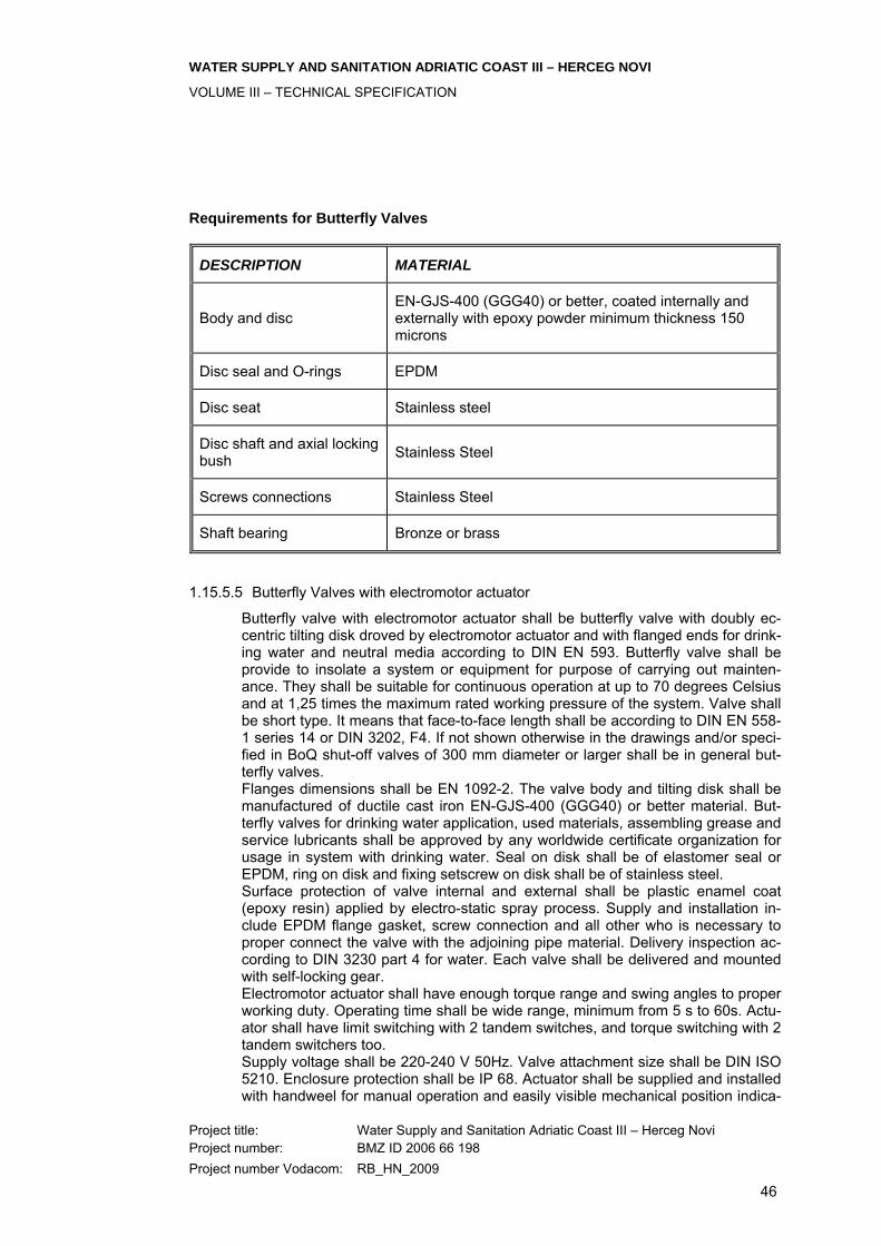
WATER SUPPLY AND SANITATION ADRIATIC COAST III – HERCEG NOVI
VOLUME III – TECHNICAL SPECIFICATION
Project title: Water Supply and Sanitation Adriatic Coast III – Herceg Novi Project number: BMZ ID 2006 66 198 Project number Vodacom: RB_HN_2009
46
Requirements for Butterfly Valves
DESCRIPTION MATERIAL
Body and disc EN-GJS-400 (GGG40) or better, coated internally and externally with epoxy powder minimum thickness 150 microns
Disc seal and O-rings EPDM
Disc seat Stainless steel
Disc shaft and axial locking bush Stainless Steel
Screws connections Stainless Steel
Shaft bearing Bronze or brass
1.15.5.5 Butterfly Valves with electromotor actuator
Butterfly valve with electromotor actuator shall be butterfly valve with doubly ec-centric tilting disk droved by electromotor actuator and with flanged ends for drink-ing water and neutral media according to DIN EN 593. Butterfly valve shall be provide to insolate a system or equipment for purpose of carrying out mainten-ance. They shall be suitable for continuous operation at up to 70 degrees Celsius and at 1,25 times the maximum rated working pressure of the system. Valve shall be short type. It means that face-to-face length shall be according to DIN EN 558-1 series 14 or DIN 3202, F4. If not shown otherwise in the drawings and/or speci-fied in BoQ shut-off valves of 300 mm diameter or larger shall be in general but-terfly valves. Flanges dimensions shall be EN 1092-2. The valve body and tilting disk shall be manufactured of ductile cast iron EN-GJS-400 (GGG40) or better material. But-terfly valves for drinking water application, used materials, assembling grease and service lubricants shall be approved by any worldwide certificate organization for usage in system with drinking water. Seal on disk shall be of elastomer seal or EPDM, ring on disk and fixing setscrew on disk shall be of stainless steel. Surface protection of valve internal and external shall be plastic enamel coat (epoxy resin) applied by electro-static spray process. Supply and installation in-clude EPDM flange gasket, screw connection and all other who is necessary to proper connect the valve with the adjoining pipe material. Delivery inspection ac-cording to DIN 3230 part 4 for water. Each valve shall be delivered and mounted with self-locking gear. Electromotor actuator shall have enough torque range and swing angles to proper working duty. Operating time shall be wide range, minimum from 5 s to 60s. Actu-ator shall have limit switching with 2 tandem switches, and torque switching with 2 tandem switchers too. Supply voltage shall be 220-240 V 50Hz. Valve attachment size shall be DIN ISO 5210. Enclosure protection shall be IP 68. Actuator shall be supplied and installed with handweel for manual operation and easily visible mechanical position indica-

WATER SUPPLY AND SANITATION ADRIATIC COAST III – HERCEG NOVI
VOLUME III – TECHNICAL SPECIFICATION
Project title: Water Supply and Sanitation Adriatic Coast III – Herceg Novi Project number: BMZ ID 2006 66 198 Project number Vodacom: RB_HN_2009
47
tor. Hand wheels shall have smooth rims and the direction of closing, which shall be clockwise. Hand wheels shall be manufacturing of cast iron or ductile cast iron or steel with appropriate anticorrosion protection. Complete of valve-actuator shall be delivered with final inspection record and quality certificate. The Butterfly Valve shall in resume comply with the following requirements
Requirements for Butterfly Valves with electromotor actuator
DESCRIPTION MATERIAL
Body and disc EN-GJS-400 (GGG40) or better, coated internally and externally with epoxy powder minimum thickness 150 microns
Disc seal and O-rings EPDM
Disc seat Stainless steel
Disc shaft and axial locking bush Stainless Steel
Screws connections Stainless Steel
Shaft bearing Bronze or brass
Actuator-valve attachment flange DIN ISO 5210
Supply voltage of actuator 220-240 V 50Hz
1.15.5.6 Butterfly Valve - Wafer type
Butterfly valve - wafer type shall be slim butterfly valve with centric disk bearing for installing between flanges with hand lever for drinking water and neutral media according to DIN EN 593. They shall be suitable for continuous operation at up to 70 degrees Celsius and at 1,25 times the maximum rated working pressure of the system. Valve shall be very short type. It means that face-to-face length shall be according to DIN EN 558-1 series 20 or DIN 3202, K1. The valve body and tilting disk shall be manufactured of ductile cast iron EN-GJS-400 (GGG40) or better material. Butterfly valve- Wafer type for drinking water ap-plication, used materials, assembling grease and service lubricants shall be ap-proved by any worldwide certificate organization for usage in system with drinking water. Seal on disk shall be of elastomer seal or EPDM, shaft shall be of stainless steel. Surface protection of valve internal and external shall be plastic enamel coat (epoxy resin) applied by electro-static spray process. Supply and installation in-clude, screw connection and all other who is necessary to proper connect the valve with the adjoining pipe material. Delivery inspection according to DIN 3230 part 4 for water. Valves shall carry identification marks and/or plates.

WATER SUPPLY AND SANITATION ADRIATIC COAST III – HERCEG NOVI
VOLUME III – TECHNICAL SPECIFICATION
Project title: Water Supply and Sanitation Adriatic Coast III – Herceg Novi Project number: BMZ ID 2006 66 198 Project number Vodacom: RB_HN_2009
48
The valve shall in resume comply with the following requirements
Requirements for Butterfly Valve - Wafer type
DESCRIPTION MATERIAL
Body and disc EN-GJS-400 (GGG40) or better, coated internally and externally with epoxy powder minimum thickness 150 microns
Disc EN-GJS-400 (GGG40) or better coated internally and externally with epoxy powder minimum thickness 150 microns or stainless steel
Disc seal EPDM
Disc shaft Stainless Steel
Screws connections Stainless Steel
Shaft bearing Bronze or brass
1.15.5.7 Non-return Valve
Non-return valve shall be butterfly valve with doubly eccentric tilting disk and with counterweight loded lever and with flanged ends for dinking water and neutral media according to DIN EN 593. Non-return valve shall be with adjustable coun-terweight on lever. Non-return valve shall be prevent back flow in pipelines. They shall be suitable for continuous operation at up to 70 degrees Celsius and at 1,25 times the maximum rated working pressure of the system. Valve shall be short type. It means that face-to-face length shall be according to DIN EN 558-1 series 14 or DIN 3202, F4. Flanges dimensions shall be EN 1092-2. The valve body and tilting disk shall be manufactured of ductile cast iron EN-GJS-400 (GGG40) or better material. Non-return valves for drinking water application, used materials, assembling grease and service lubricants shall be approved by any worldwide certificate organization for usage in system with drinking water. Seal on disk shall be of elastomer seal or EPDM, ring on disk and fixing setscrew on disk shall be of stainless steel. Surface protection of valve internal and external shall be plastic enamel coat (epoxy resin) applied by electro-static spray process. Supply and installation include EPDM flange gasket, screw connection and all other who is necessary to proper connect the valve with the adjoining pipe mate-rial. Delivery inspection according to DIN 3230 part 4 for water. Valves shall carry identification marks and/or plates. The Non-return valve shall in resume comply with the following requirements
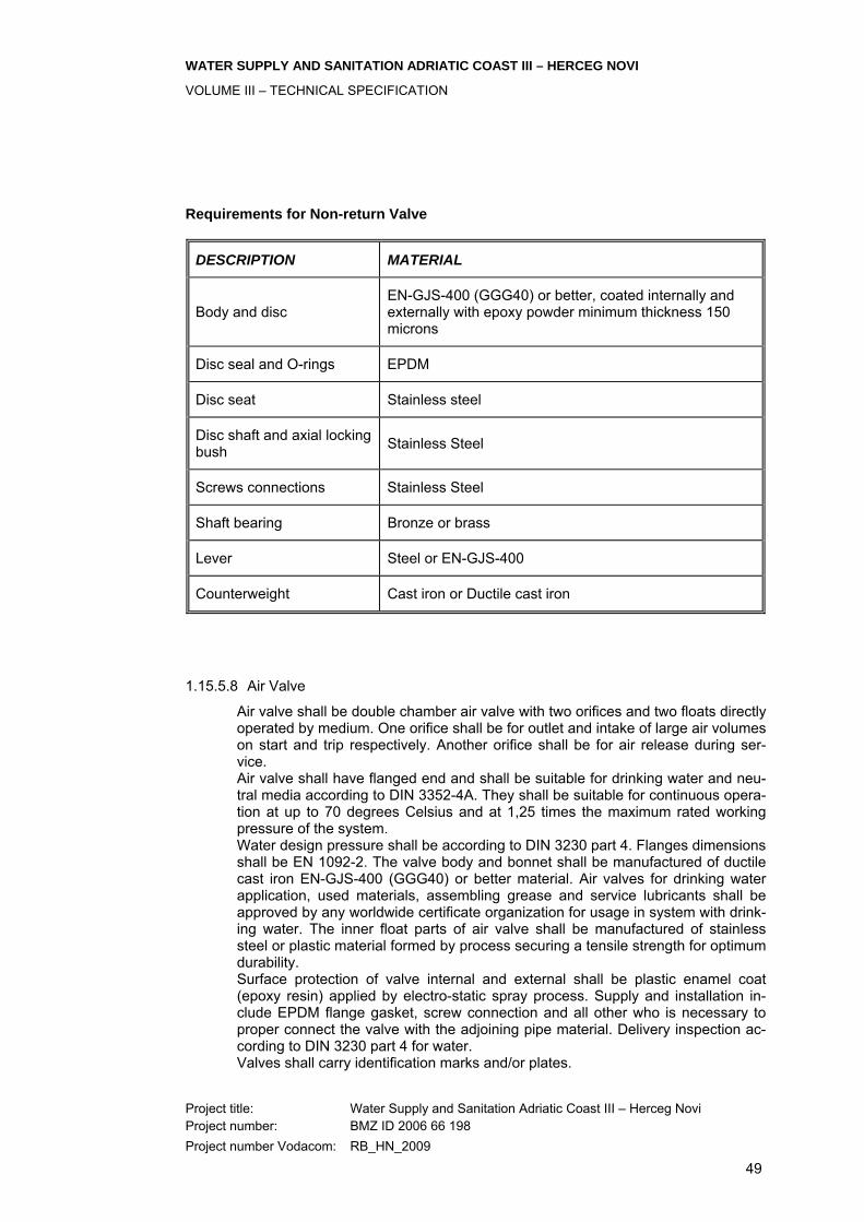
WATER SUPPLY AND SANITATION ADRIATIC COAST III – HERCEG NOVI
VOLUME III – TECHNICAL SPECIFICATION
Project title: Water Supply and Sanitation Adriatic Coast III – Herceg Novi Project number: BMZ ID 2006 66 198 Project number Vodacom: RB_HN_2009
49
Requirements for Non-return Valve
DESCRIPTION MATERIAL
Body and disc EN-GJS-400 (GGG40) or better, coated internally and externally with epoxy powder minimum thickness 150 microns
Disc seal and O-rings EPDM
Disc seat Stainless steel
Disc shaft and axial locking bush Stainless Steel
Screws connections Stainless Steel
Shaft bearing Bronze or brass
Lever Steel or EN-GJS-400
Counterweight Cast iron or Ductile cast iron
1.15.5.8 Air Valve
Air valve shall be double chamber air valve with two orifices and two floats directly operated by medium. One orifice shall be for outlet and intake of large air volumes on start and trip respectively. Another orifice shall be for air release during ser-vice. Air valve shall have flanged end and shall be suitable for drinking water and neu-tral media according to DIN 3352-4A. They shall be suitable for continuous opera-tion at up to 70 degrees Celsius and at 1,25 times the maximum rated working pressure of the system. Water design pressure shall be according to DIN 3230 part 4. Flanges dimensions shall be EN 1092-2. The valve body and bonnet shall be manufactured of ductile cast iron EN-GJS-400 (GGG40) or better material. Air valves for drinking water application, used materials, assembling grease and service lubricants shall be approved by any worldwide certificate organization for usage in system with drink-ing water. The inner float parts of air valve shall be manufactured of stainless steel or plastic material formed by process securing a tensile strength for optimum durability. Surface protection of valve internal and external shall be plastic enamel coat (epoxy resin) applied by electro-static spray process. Supply and installation in-clude EPDM flange gasket, screw connection and all other who is necessary to proper connect the valve with the adjoining pipe material. Delivery inspection ac-cording to DIN 3230 part 4 for water. Valves shall carry identification marks and/or plates.

WATER SUPPLY AND SANITATION ADRIATIC COAST III – HERCEG NOVI
VOLUME III – TECHNICAL SPECIFICATION
Project title: Water Supply and Sanitation Adriatic Coast III – Herceg Novi Project number: BMZ ID 2006 66 198 Project number Vodacom: RB_HN_2009
50
The Air Valve shall in resume comply with the following requirements
Requirements for Air Valves
DESCRIPTION MATERIAL
Body and bonnet EN-GJS-400 (GGG40) or better, coated with epoxy powder, minimum thickness 150 microns
Wedge EN-GJS-400 (GGG40) or better, fully encapsulated by vulcanized EPDM
Connection bolts Stainless steel
Stem Stainless steel
Stem nut and bearing Brass or bronze
Bonnet and bush seals EPDM
1.15.5.9 Dismantling Joints
Dismantling joints shall be installed were indicated on the drawings for convenient installation or re-installation of valves or similar items. Dismantling joints shall be for permanent contact with potable water at admissible working temperature up to 50 °C and working pressure 10 bar. Dismantling joints determinates pipe length deflections, makes assembly and substitution of already built valves easier. Com-pensator and dismantling piece functionality is not possible to combine into one valve. Flanges dimensions shall be EN 1092-2. The valve body and bonnet shall be manufactured of ductile cast iron EN-GJS-400 (GGG40) or better material. Body, packing bonnet, movable and adjustable piece are made out of ductile cast iron, guide-ring is made out of brass, bolts, washers and nuts are out of steel hot zinc plated or stainless steel. Dismantling joints shall be install in pipe axis direction, prevent individual parts crossing. In case of gland packing leakage screw evenly packing bonnet nuts. Surface protection of internal and external shall be plastic enamel coat (epoxy re-sin) applied by electro-static spray process. Tested with water as per EN 12266-1, test P10 and P11. Leak is unacceptable.
1.15.5.10 Flap valve
Flap valve shall be installed on the flush pipeline outlet. Flap valve shall not be for permanent contact with potable water at admissible working temperature up to 50 °C and working overpressure max. 16 bar. On one side of valve shall be flange dimensions according to EN 1092-2. The valve body and flap shall be manufac-tured of ductile cast iron EN-GJS-400 (GGG40) or better material. Body, packing bonnet, movable and adjustable piece are made out of ductile cast iron, guide-ring

WATER SUPPLY AND SANITATION ADRIATIC COAST III – HERCEG NOVI
VOLUME III – TECHNICAL SPECIFICATION
Project title: Water Supply and Sanitation Adriatic Coast III – Herceg Novi Project number: BMZ ID 2006 66 198 Project number Vodacom: RB_HN_2009
51
is made out of brass, bolts, washers and nuts are out of steel hot zinc plated or stainless steel. Surface protection of valve internal and external shall be plastic enamel coat (epoxy resin) applied by electro-static spray process. UV protection of external surfaces is preferable.
1.15.5.11 Valves and Penstocks
All valves and penstocks shall be best water works quality and suitable for use in water or wastewater works (as appropriate) at all temperatures up to 25°C. Valve bodies shall give the following information: • manufacturer’s name; • hydraulic test pressure; • size of valve; • direction of flow ‘arrow’. The operating gear of valves and penstock gates shall be such that one man can open and close the valve against an unbalanced head 15% in excess of the max-imum to be encountered in service. Where necessary, arrangements shall be pro-vided with gearing to achieve this requirement. The maximum couple which can be exerted by one man shall be taken as 13Nm and the maximum force as 25 N. Where specified, valves 300mm nominal bore and over shall be fitted with by-passes with isolating valves. Gate valves shall be provided with renewable seats and it shall be possible to re-move the gates without removing the valve body from the pipework. Penstock gates shall be provided with renewable sealing faces. Unless otherwise specified or otherwise determined by the Contractor under his responsibility for checking maximum working and test pressures, all standard valves shall have flanged joints of pressure rating PN 10 standard flange drilling matching with flanges provided on standard pipes and fittings. The operation of all valves shall be such that turning the handwheel or tee-key in a clockwise direction closes the valves. All materials shall comply with the appropriate German Standards and shall be subject to the Engineer’s approval. All castings shall be free of blowholes and other defects. Sluice valves and butterfly valves shall be suitable for flow in either direction. All standard valves shall be suitable for frequent operation and for infrequent op-eration after long periods in the open or closed condition and shall satisfy the re-quirements of the DIN open and closed end tests.

WATER SUPPLY AND SANITATION ADRIATIC COAST III – HERCEG NOVI
VOLUME III – TECHNICAL SPECIFICATION
Project title: Water Supply and Sanitation Adriatic Coast III – Herceg Novi Project number: BMZ ID 2006 66 198 Project number Vodacom: RB_HN_2009
52
Butterfly valves shall be installed in the pipework in such a manner that they can easily be removed from the line for dismantling and replacement of the seats, de-signed to give minimum leakage, unless otherwise specified. Non-return valves on the main pump delivery branches shall possess high speed closing characteristics, with minimum shock on closing. Packed glands shall be arranged for easy replacement of the packing, which shall be accessible without removal of the valve from the pipe. Precautions shall be taken to prevent corrosion of the valve spindles in contact with the gland packing. Each valve or penstock gate or its operating equipment, shall bear an approved brass nameplate stating its function in english and arabic language. Valves, cocks and operating spindles which are for submerged operation, shall be independent of external lubrication.
Spindle Operation
Unless otherwise specified, all valves shall be located and orientated in readily accessible positions with handwheels conveniently arranged for ease of opera-tion. Where this requirement is impracticable or would lead to complications, operating spindles shall be taken vertically to headstocks for manual operation. Chain operated wheels shall not be incorporated in the arrangements. Tee-key operation of valves and penstocks shall only be adopted in unavoidable situations or for secondary and only occasionally used purposes such as under-ground main valve by-passes, air valve isolation, minor drainage valves. In such cases the spindles shall be fitted with a cast iron detachable cap manufactured to and of identical shape to the valve spindle caps. All valves operated by tee-key shall be brought to a position suitable and conve-nient for operation by a tee-key inserted through a cast iron cover provided in the valve chamber roof or access cover. Extension spindles shall be provided where necessary to achieve this requirement and also any gearing required. Operating and extension spindles shall be provided with suitable bearings which are rigidly held on brackets or stays. Bearings and spindles shall be suitably pro-tected against corrosion. Where a valve does not require an operating or extension spindle, the valve shall be provided with a properly fitting cap to DIN and designed to protect the valve spindle against damage. 6 No. DIN standard tee-keys shall be provided for each type of cap or stop cock in the works.
WATER SUPPLY AND SANITATION ADRIATIC COAST III – HERCEG NOVI
VOLUME III – TECHNICAL SPECIFICATION
Project title: Water Supply and Sanitation Adriatic Coast III – Herceg Novi Project number: BMZ ID 2006 66 198 Project number Vodacom: RB_HN_2009
53
Headstocks shall be designed over at least: (a) all external main low isolating and flow control valves; (b) all external waste water valves; (c) all weir and sluice penstocks; (d) other works valves and penstocks such as main tank feeds, tank by-
passes, reservoirs, scours etc. within the scope of design. Headstocks shall be purpose made cast iron pedestal units. Extension spindle operation by direct handwheel attachment shall not be adopted unless so speci-fied. Where specified valves and penstocks shall be power operated by electric or pneumatic actuators, each actuator shall have local manual ‘override’ facilities. No alternative systems shall be offered. Penstock gates and valves of 50mm nominal bore and over shall be fitted with mechanical position indicators to show the amount which the valve or penstock gate is open or closed in relation to its full travel.
Handwheels
Operating handwheels for gate valves and penstocks shall be cast iron and gen-erally to the DIN pattern, materials specification and finishes set out. All handwheels on valves over 50mm diameter shall be fitted with a circular in-scribed brass disc with an arrow indicating English and Montenegrin language. Plates on handwheels for valves over 150mm diameter shall in addition, have a simple bilingual inscription denoting the function e.g., “Inlet”. External handwheels shall be fitted with proprietary integral locking device to pre-vent operation by unauthorised persons. A padlock and chain will not be accept-able.
1.15.5.12 Sluice Valves
Sluice gate valves shall be of the double-flanged cast iron wedge-gate type unless otherwise specified. They shall have a cast iron body with renewable non-ferrous faces on body and wedge and a bolt-on cast iron bonnet to facilitate gate removal. Sluice valves shall conform to the requirements of DIN for PN 6 (i.e. 6 bar) pres-sure rating, water works valves. Valve spindles for the wastewater works shall be generally of the external screw type.
WATER SUPPLY AND SANITATION ADRIATIC COAST III – HERCEG NOVI
VOLUME III – TECHNICAL SPECIFICATION
Project title: Water Supply and Sanitation Adriatic Coast III – Herceg Novi Project number: BMZ ID 2006 66 198 Project number Vodacom: RB_HN_2009
54
All sluice valves shall be subjected to an ‘open-ended’ works test and the manu-facturer shall issue test certificates to this effect. Where sluice valve above 350 mm bore are mounted with the spindle in the hori-zontal plane the valve bodies shall be fitted with renewable non-ferrous machined gate slides and the gates with renewable non-ferrous shoes accurately machined to reduce sliding friction. Valve stems shall be of forged aluminium bronze, machined all over with a ma-chine cut robust trapezoidal or square form thread, operating in a gunmetal nut. Stem seals shall be of the stuffing box and gland form arranged for easy replace-ment of packing and shall be accessible for maintenance without removal of the valve from service. Extension spindles, headstocks and foot brackets shall be provided where neces-sary. Extended spindle installations shall include all necessary brackets, interme-diate supports etc. Headstocks for non-rising spindle installations shall incorporate a valve position indicator. Extension spindles shall be of a stainless steel and shall conform with the re-quirements for valve stems with the exception of non-threaded sections which may be of mild steel. Extension spindle couplings shall be flanged, drilled and provided with a not and bolt for securing the spindle to the valve stem which shall likewise be drilled to accept the bolt. All handwheels, headstocks, foot brackets and guide brackets shall be of cast iron. Fixing nuts and bolts supplied by the manufacturer shall comply with the appropri-ate DIN specifications and standards. Those subject to vibration shall be fitted with spring ring or locking tabs. All valves shall be works tested hydraulically to pressures of 10 bar, and be suita-ble for working at pressures of 6 bar. All valves shall be prepared and painted in accordance with the General Specification, Painting and Protective Coatings. All materials used in manufacture of the valves shall conform to the following min-imum standards: Cast iron* Grade 220 Gunmetal Grade LG2 Aluminium Bronze Grade CA104 Stainless Steel Grade 431 S29 *Spheroid Graphite Iron may be used as an alternative to Cast Iron for Water-works Standard Valves.
1.15.5.13 Reflux Valves

WATER SUPPLY AND SANITATION ADRIATIC COAST III – HERCEG NOVI
VOLUME III – TECHNICAL SPECIFICATION
Project title: Water Supply and Sanitation Adriatic Coast III – Herceg Novi Project number: BMZ ID 2006 66 198 Project number Vodacom: RB_HN_2009
55
Reflux valves shall be double flanged cast iron unless otherwise specified. They shall be of the quick acting non slam single or multi door type designed to mini-mise slam on closure by means of heavy gunmetal faced doors weighted as ne-cessary and with stainless steel hinge pins. The valves shall be fitted with renew-able door sealing faces which shall be positively fixed. Tilting valve disc shall open under positive flow to a degree corresponding to the flowrate. With decreasing flow, the disc shall swing back towards the closed posi-tion. Valve body length shall be of the short length series according to DIN 3202 Parts 4 and 5, DIN EN 558 and DIN EN 12982. The counter-weight of the non-return valve has to be provided with a removable protection cover. The cover shall protect the operators from accidents in case of slamming of the counter-weight. Easy dismantling of the cover has to be possible. All reflux valves shall be suitable for operating in the horizontal plane unless oth-erwise specified. Covers shall be provided to allow ample access for cleaning and service and shall be supplied complete with tapped bosses fitted with Air release cocks. Valves shall carry identification marks and/or plates in accordance with DIN. Valves shall be flanged and sized such that the velocity through the valve when fully open does not exceed 2.25 metres per second at the rated output. All nuts and studs subject to vibration shall be fitted with spring rings or locking tabs. All valves shall be prepared and painted in accordance with the general Specifica-tion, Painting and Protective Coating. Design according to DIN EN 12255-1 and DIN 19569 Part 2-3. All materials used in the manufacture of reflux valves shall conform to the follow-ing minimum standards: Cast Iron Grade 220 Gunmetal Grade LG2 Stainless Steel Grade 431 S29 Materials: Body: Ductile cast iron Disc: Ductile cast iron Seat faces: Corrosion resistant, wear resistant nickel overlay weld, micro finished

WATER SUPPLY AND SANITATION ADRIATIC COAST III – HERCEG NOVI
VOLUME III – TECHNICAL SPECIFICATION
Project title: Water Supply and Sanitation Adriatic Coast III – Herceg Novi Project number: BMZ ID 2006 66 198 Project number Vodacom: RB_HN_2009
56
1.15.5.14 Penstocks
Water treatment works penstocks shall be of the rising spindle type, manufactured in close grained cast iron, the frame and guide in one piece cast construction or with the guides dowelled and bolted to the frame. Frames shall incorporate a rectangular or circular opening with integral spigot on the back. The gate shall be of one piece cast construction with vertical and horizontal ribs, a reinforced pocket to receive a gunmetal thrust nut, pads to receive wedges and reinforced periphery around the backside machined for nonferrous seating faces. Guide rails shall be of such length as to retain at least one half of the vertical heights of the slide when in the fully open position. Grooves running the full length of the guide rail shall be accurately matched to receive non-ferrous slide tongues. The manufacture and assembly shall be such as to ensure accuracy in mating the frame and door faces and tight closure while maintaining freedom of gate move-ment during operation and minimizing sliding wear of the sealing faces. They shall incorporate adjustable wedges or swiveling cams and actuating pegs manufac-tured from a non-corrodible material. Metal sealing faces shall be formed from accurately machined gunmetal or bronze strips bedded and fixed to the machined recesses in the frame and gate. The fac-es of the strips shall then be brought together in the operating position and hand scraped to a watertight finish. Penstocks shall be site tested with a feeler gauge to a non-acceptance of 0.5 mm between sealing faces when closed. Unless otherwise stated each penstock shall be provided with a suitable handwheel of adequate diameter for the duty required, or gearing shall be sup-plied where necessary to ensure that the required operating force applied by hand to the rim of the wheel or geared handle does not exceed 250N. Gearboxes of handwheels shall have cast on them the direction of closing which shall be clockwise and vandal and weather-proof clear polycarbonate tube covers shall be securely fitted to protect the threads of rising spindles. The operator facili-ties shall be clearly and permanently engraved to indicate the position of the penstock to which it is fitted. Spindles shall have machine cut robust trapezoidal or square form threads. They shall be of bronze, running in gunmetal nuts. Extension spindle coupling shall be of the flange type and they shall be drilled and provided with a nut and bolt for se-curing the spindle to the penstock spindle head which shall likewise be drilled to receive the bolt. Where penstocks are specifically required to be operated by tee-keys, spindle caps of the specified type shall be fitted. The caps shall be drilled and each pro-vided with nut and bolt for securing to the spindle which shall also be drilled.
WATER SUPPLY AND SANITATION ADRIATIC COAST III – HERCEG NOVI
VOLUME III – TECHNICAL SPECIFICATION
Project title: Water Supply and Sanitation Adriatic Coast III – Herceg Novi Project number: BMZ ID 2006 66 198 Project number Vodacom: RB_HN_2009
57
All handwheels, headstocks, foot brackets and guide brackets shall be of cast iron. Guide brackets shall be adjustable. Fixing nuts and bolts shall be specified in the appropriate clauses herein. Penstocks shall be prepared and painted in accordance with the Specification for Painting and Protective Coating. Penstocks shall be structurally designed for inside sealing or outside sealing pressures of 5 times the maximum possible hydraulic loading which they could be subjected to on site. Those with outside sealing pressures may have side wedges only. All penstocks shall be delivered with a temporarily attached template in order to facilitate accurate installation of the frame and fittings. Weir penstocks, where specifically required, shall be designed for inside sealing pressure application and shall incorporate a removable bronze sharp edges over-flow sill. Pipe entrance penstocks, where specifically required shall be faced and studded on the back spigot to suit the NP 6 pipe flange. All materials used in the manufacture of penstocks shall conform to the following minimum standards: Cast Iron Grade 180 Gunmetal Grade LG2 Stainless Steel Grade 316 S16 Manganese Steel Grade 150 M19 A: General • Design according to DIN EN 12255-1 and DIN 19569 Part 2-3 • Penstock comprising: guide frame, penstock frame, penstock yoke, rising
spindle for easy maintenance where possible, protection tube for spindle. • Sealing of penstock plate all round by wastewater resistant and easily ex-
changeable seal • Seal to be attached to penstock plate to facilitate exchange of seal during
operation of sewage plant • Seal tightness according to Din 19569, part 4 • Spindle support in water and dustproof axial ball bearings • Spindle nut with lubrication nipple, nut made from red brass • Penstock with mechanical position indicator B: Driving system The drive system shall comprise. • Electric control device with 3-phase motor, direct coupling or by angular
gear
WATER SUPPLY AND SANITATION ADRIATIC COAST III – HERCEG NOVI
VOLUME III – TECHNICAL SPECIFICATION
Project title: Water Supply and Sanitation Adriatic Coast III – Herceg Novi Project number: BMZ ID 2006 66 198 Project number Vodacom: RB_HN_2009
58
• Drive unit rated for 600 switch operations per hour • Thermoelement in coil for motor protection • Stroke and torque limit switches • Electronic position indicator • Potential-free contact points for operational and fault signals • Integrated switch “open-stop-close” • Integrated key-operated switch for “local-0-remote“ operation • Drive unit to be equipped with heating to prevent condensation • Protection type IP 67 / 54 / explosion proof type (if applicable) • Insulation class F • Handwheel shall be provided for emergency operation in case of power
failure • Clutch shall disengage handwheel automatically in case drive starts au-
tomatically
1.15.5.15 Air and Gas Relief Valves
Air and gas relief valves shall be VAG VENT-O-MAT AW® Automatic Air valve or equivalent. The inlet flange shall be faced and drilled. The valves shall be adequately sized for the release of gas from the pipeline (or other container) without restriction of rate of filling or flow due to back pressure and also to allow admission of air during pipeline emptying at a rate sufficient to prevent excessive depression of pressure in the pipe. Valves shall be designed to prevent the operating elements being in contact with the pipeline liquid by approved means such as the provision of an auxiliary float and chamber sufficiently large to isolate the orifice valves and seats throughout the rated operational range. Air valves shall be fitted with an isolating sluice valve and gearing shall be pro-vided where necessary to facilitate operation. All air and gas relief valves and associated isolating valves shall be works tested hydraulically and capable of withstanding test pressure of 25 bar and working pressures of 16 bar. All valves and operating linkages shall be prepared and painted in accordance with the General Specification for Painting and Protective Coating. Design The air and gas relief valves shall be automatic air valve, PN 10, DN 50....200 suitable for sewage, in compact single chamber design with surge damping de-vice. The valves shall be designed for high volume air discharge or air intake dur-ing filling or draining of pipe system, venting of small volumes of air under operat-ing pressure, body and bonnet of stainless steel (A2), float of plastic (PE-HD), gaskets of rubber (NBR), flange dimensions to DIN 2501-1, PN 10, connecting flange with stud-bolts Product features Single chamber air valve, directly operated by the flow medium, compact design, very few components, triple function, large orifice for outlet and intake of large air volumes on start and trip, respectively, of pumps medium anti-surge orifice to al-

WATER SUPPLY AND SANITATION ADRIATIC COAST III – HERCEG NOVI
VOLUME III – TECHNICAL SPECIFICATION
Project title: Water Supply and Sanitation Adriatic Coast III – Herceg Novi Project number: BMZ ID 2006 66 198 Project number Vodacom: RB_HN_2009
59
leviate surges due to high velocity air discharge small orifice for discharge of pressurized air during service Materials Body, top flange and mounting parts of austenitic alloy steel 1.4301 (AISI 304) All floats of PE-HD Field of application Minimum internal pressure required to seal the air orifices: 0.5 bar
1.15.5.16 Butterfly Valves
Butterfly valves up to and including 1000 mm nominal diameter shall conform to German standards (DIN) for PN 6 (i.e. 6 bar) pressure rating. If butterfly valves are required for pressure ratings above 6 bar or for sizes above 1000 mm nominal diameter, they shall comply with the materials and other relevant provisions of the standards. Except where otherwise specified, all butterfly valves shall be resilient seated and shall give tight closure against unbalanced water pressure in either direction. The unbalanced water pressure shall be the design pressure rating of the valve. The valve seat shall be replaceable and be formed of rubber or other approved resilient and durable material. The valve seat shall be securely clamped into a machined groove in the valve body or to the edge of the disc by seat retention members, or other equivalent retention device, in such a manner as to prevent leakage of water under the seats and to hold the seat securely in position during opening and closing of the valve disc. The seat retention members shall be of stainless steel shall be securely fastened to the body or disc with stainless steel fasteners. Disc edges shall be machined with rounded corners and shall be polished to a smooth finish. The valve disc shall rotate through an angle of 90 degrees from the fully opened to the fully closed position and the seat shall be of such design as to allow the valve disc to seat at an angle normal to the axis of the pipe when the disc is in the fully closed position. Adjustable mechanical stop shall be provided in the valve body to present over-travel of the valve disc in both the open and closed positions. these stops shall be capable of absorbing full operating torque with a minimum design safety factor of five. Butterfly valve spindles shall be horizontal when mounted. The valve shaft shall be fabricated of stainless steel and may be in one piece or attached as two stub ends on opposite sides of the disc. The means of the at-tachment of the shaft to the disc shall be using fixings in a homogenous corrosion-resistant material of a pattern which precludes the assembly becoming loose in operational service. Grub screws, pins (parallel or taper) or clamps will not be ac-ceptable. The shaft and disc fixing shall be capable of absorbing the full operating torque with a minimum design safety factor of five. Shaft seals, when used, shall

WATER SUPPLY AND SANITATION ADRIATIC COAST III – HERCEG NOVI
VOLUME III – TECHNICAL SPECIFICATION
Project title: Water Supply and Sanitation Adriatic Coast III – Herceg Novi Project number: BMZ ID 2006 66 198 Project number Vodacom: RB_HN_2009
60
be rubber 0-ring type. Packing shall be either rubber 0-ring or self adjusting che-vron type. When all the seat retention members are in place, the finished edges shall fit closely and the surface shall be smooth with all fastenings set flush in the water passage so as to offer the least resistance possible to the flow of water through the valve. Valve seats which extend over the face of the flanges to secure the seat in place, or which require surface grinding and/or hand fitting of the disc; or designs which require the adjoining pipe flange to retain the seat in place and resist line pres-sure, will not be acceptable. Operating gear for butterfly valves shall be of the fully enclosed type. Valves shall be suitable for operation by one man at all pressure conditions that can apply. A valve position indicator shall be provided. Where a handwheel is used for operat-ing the valve, the indicator shall be clearly visible from the handwheel operating position. All butterfly valves shall be tested at the manufacturer’s works under ‘open end’ conditions. The seat test shall be for tight closure under maximum unbalanced water test pressure in either direction. The maximum permissible leakage for each valve shall be acc. to DIN 19569-4. The Contractor shall provide details of the materials of manufacture and design of butterfly valves, and shall provide evidence to show that the proposed seating ma-terials and seating designs have given satisfactory performance in similar condi-tions to those applying under the Contract. Valves shall carry identification marks and/or plates and those for use on process plant shall carry an additional brass plate carrying a valve identification and a brief description of its function. Unless otherwise specified valves shall have 6 bar flanges and be drilled and shall be capable of withstanding the same pressure as the pipeline on which they operate. All nuts and studs subject to vibration shall be fitted with spring ring or locking tabs. All valves and operating linkages shall be prepared and painted in accordance with the General Specification for Painting and Protective Coating. All materials used in manufacture of butterfly valves shall conform to the following minimum standards: Body and Disc - Cast Iron to Grade 220 or Spherical Graphite Iron Shaft - Stainless Steel Sealing Ring & Seat - Gunmetal

WATER SUPPLY AND SANITATION ADRIATIC COAST III – HERCEG NOVI
VOLUME III – TECHNICAL SPECIFICATION
Project title: Water Supply and Sanitation Adriatic Coast III – Herceg Novi Project number: BMZ ID 2006 66 198 Project number Vodacom: RB_HN_2009
61
1.15.5.17 Ball Valves (< DN 100)
The ball valve shall have a smooth, unobstructed passage for installation in pipe-lines and shall be suitable for flowrate control. • Suitable for installation between flanges • Materials: - Body: ductile cast iron - Ball: stainless steel - Shaft: stainless steel, shaft sealed by O-rings EPDM - Peripheral seal: EPDM, exchangeable
1.15.5.18 Ball Valves (≥ DN 100) The ball valve shall have a smooth, unobstructed passage for installation in pipe-lines and shall be suitable for flowrate control. • Suitable for installation between flanges • Stop globe double-eccentric sealing • Materials: - Body: ductile cast iron - Body seal face with built-up weld of stainless steel 1.4502 corrosion resis-
tant and smooth finished surface - Ball: stainless steel - Shaft: stainless steel, shaft sealed by O-rings
EPDM - Peripheral seal: EPDM, exchangeable • Bearing assembly: - Bearing brush: - Sealing part: thrust ring: special ductile cast iron - Bearing flange: cover: special ductile cast iron - Bolts: stainless steel 1.4571 • Gearing: - Corrosion resistant worm gear in cast iron housing, protection class IP 67
/ 54 / explosion proof type (if applicable) - Limit stop in open and closed positions - Mechanical position indicator “open – shut” - Fluid grease filling, maintenance free
1.15.5.19 Flap Valves
Flap valves shall be round or rectangular, single door bitumen coated, cast iron double hung tidal type flap valves, with the clear opening dimensions designed to pass the required discharge.

WATER SUPPLY AND SANITATION ADRIATIC COAST III – HERCEG NOVI
VOLUME III – TECHNICAL SPECIFICATION
Project title: Water Supply and Sanitation Adriatic Coast III – Herceg Novi Project number: BMZ ID 2006 66 198 Project number Vodacom: RB_HN_2009
62
Flap valves shall be fitted with phosphate or bronze or stainless steel or similar approved corrosion resistant metal faces and hinge pins and shall have a galva-nised mild steel lifting eye. Flap valves shall be designed to withstand a working pressure equivalent to 8.0 m of water and shall be tested after installation with a feeler gauge to a non-acceptance of 0.05 l/sec /m between sealing faces when closed.
1.15.5.20 Stop-log
Stop-logs on wastewater treatment process shall be of proprietary manufacture in appropriate non-ferrous materials resistant to H2S attack (e.g. aluminum, stain-less steel etc.).
1.15.5.21 Hand operated rising spindle headstocks
Hand operated rising spindle headstocks shall be purpose made spindle enclos-ing pedestal pillars manufactured in close grained cast iron, either of the handwheel or the single or double gear crank operated type. Lift nuts shall be in cast bronze threaded to fit the rising stem. Spindle thrusts shall be taken on ball or roller bearings provided above and below the flange on the lift nut and designed to take five times the maximum thrust de-veloped in opening and closing the gate. Gears shall be of cast bronze, accurately machined with cut teeth, and smooth running with similar shafts in bronze sleeve bearings or roller bearings of ample size. The gear box shall be covered by a removable flanged cast iron cover dome. All gears and bearings shall be enclosed in the cast-iron housing. Fittings shall be provided so that all gears and bearings can be periodically lubricated. The removable cast iron crank shall be fitted with a brass rotating handle, set with its axis nominally 1.0 m above ground or floor level. The maximum crank radius shall be 350 mm, the effort require shall be less than 25 kg and the direction of ro-tation for closing is clockwise. The direction of opening shall be marked and anno-tated on the headstock casting. The rising stem unit shall be provided with a galvanised steel spindle cover of suf-ficient diameter and length to permit full travel of the threaded stem without ob-struction. The top of the stem shall be capped and the bottom flanged to suit the housing or adaptor plate. Each penstock shall be provided with a brass position

WATER SUPPLY AND SANITATION ADRIATIC COAST III – HERCEG NOVI
VOLUME III – TECHNICAL SPECIFICATION
Project title: Water Supply and Sanitation Adriatic Coast III – Herceg Novi Project number: BMZ ID 2006 66 198 Project number Vodacom: RB_HN_2009
63
indicator to show the position of the gate at all times. Indication shall be in the support stem through a brass faced and calibrated slot. Headstocks shall be prepared and painted in accordance with the General Paint-ing and Protective Coatings Specifications. Headstocks shall be vertical. All mountings shall be through a rigid rectangular plate with a least 4 fixing holes. Base fixings shall be designed for the peak thrust with a factor of safety of 5. The design thrust shall be stated on the Contractor’s drawings.
1.15.5.22 Hand operated non-rising spindle headstocks
Non-rising spindle headstocks for valves shall be proprietary vertical spindle en-closing pedestal pillars, fitted with a valve position indicator mechanism, cast iron handwheel and suitably fitted with robust bearings and bushes, and designed for prolonged external exposure. All mountings shall be through a rigid rectangular base plate with at least 4 fixing holes. Handwheels shall be horizontal, nominally 1.0 m above ground or floor lev-el. The headstocks shall be prepared and painted in accordance with the General Painting and Protective Coating.
1.15.5.23 Underground Hydrants
Underground hydrants shall be according DIN 3221 with double shut - off device. Lenght of hydrants not exceed 550 mm. Flanges dimensions shall be EN 1092-2. The body, stopper disk, bayonet catch and cover shall be manufactured of ductile cast iron EN-GJS-400 (GGG40) or better material. Seat bush and spindle nut shall be manufactured of brass. Stem and spindle shall be stainless steel. Underground Hydrants for drinking wa-ter application, used materials, assembling grease and service lubricants shall be approved by any worldwide certificate organization for usage in system with drink-ing water.. Hydrant shall have protection from the penetration of dirt contamina-tion, and backwashing at full rated capacity. Hydrant shall have surface suscepti-ble to incrustation. The inner float parts shall be manufactured of stainless steel or plastic material formed by process securing a tensile strenght for optimum durability. Surface pro-tection of valve internal and external shall be plastic enamel coat (epoxy resin) applied by electro-static spray process. Supply and installation include adequate street covers according DIN 4055, EPDM flange gasket, screw connection and all other who is necessary to proper connect the valve with the adjoining pipe materi-al. Delivery inspection according to DIN 3230 part 4 for water. Valves shall carry identification marks and/or plates. The Gate Valve shall in resume comply with the following requirements

WATER SUPPLY AND SANITATION ADRIATIC COAST III – HERCEG NOVI
VOLUME III – TECHNICAL SPECIFICATION
Project title: Water Supply and Sanitation Adriatic Coast III – Herceg Novi Project number: BMZ ID 2006 66 198 Project number Vodacom: RB_HN_2009
64
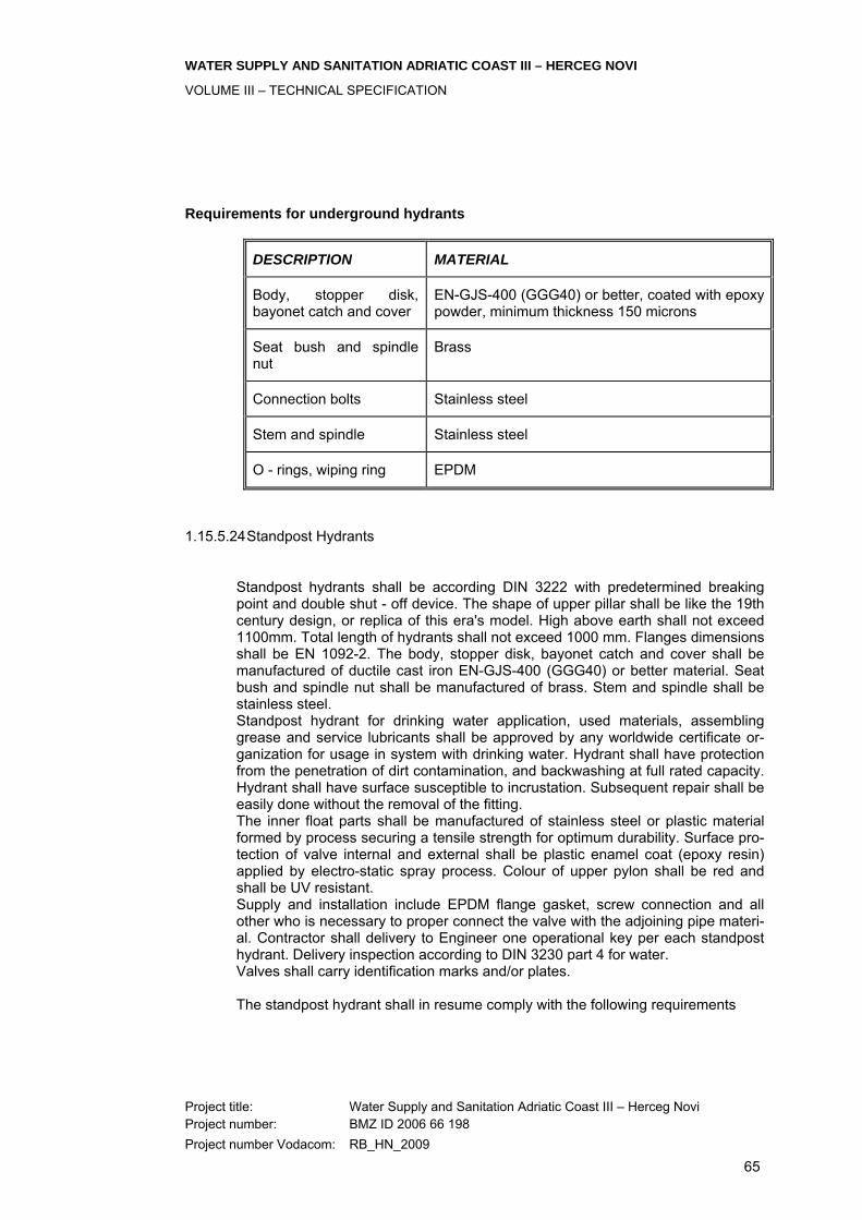
WATER SUPPLY AND SANITATION ADRIATIC COAST III – HERCEG NOVI
VOLUME III – TECHNICAL SPECIFICATION
Project title: Water Supply and Sanitation Adriatic Coast III – Herceg Novi Project number: BMZ ID 2006 66 198 Project number Vodacom: RB_HN_2009
65
Requirements for underground hydrants
DESCRIPTION MATERIAL
Body, stopper disk, bayonet catch and cover
EN-GJS-400 (GGG40) or better, coated with epoxy powder, minimum thickness 150 microns
Seat bush and spindle nut
Brass
Connection bolts Stainless steel
Stem and spindle Stainless steel
O - rings, wiping ring EPDM
1.15.5.24 Standpost Hydrants
Standpost hydrants shall be according DIN 3222 with predetermined breaking point and double shut - off device. The shape of upper pillar shall be like the 19th century design, or replica of this era's model. High above earth shall not exceed 1100mm. Total length of hydrants shall not exceed 1000 mm. Flanges dimensions shall be EN 1092-2. The body, stopper disk, bayonet catch and cover shall be manufactured of ductile cast iron EN-GJS-400 (GGG40) or better material. Seat bush and spindle nut shall be manufactured of brass. Stem and spindle shall be stainless steel. Standpost hydrant for drinking water application, used materials, assembling grease and service lubricants shall be approved by any worldwide certificate or-ganization for usage in system with drinking water. Hydrant shall have protection from the penetration of dirt contamination, and backwashing at full rated capacity. Hydrant shall have surface susceptible to incrustation. Subsequent repair shall be easily done without the removal of the fitting. The inner float parts shall be manufactured of stainless steel or plastic material formed by process securing a tensile strength for optimum durability. Surface pro-tection of valve internal and external shall be plastic enamel coat (epoxy resin) applied by electro-static spray process. Colour of upper pylon shall be red and shall be UV resistant. Supply and installation include EPDM flange gasket, screw connection and all other who is necessary to proper connect the valve with the adjoining pipe materi-al. Contractor shall delivery to Engineer one operational key per each standpost hydrant. Delivery inspection according to DIN 3230 part 4 for water. Valves shall carry identification marks and/or plates. The standpost hydrant shall in resume comply with the following requirements

WATER SUPPLY AND SANITATION ADRIATIC COAST III – HERCEG NOVI
VOLUME III – TECHNICAL SPECIFICATION
Project title: Water Supply and Sanitation Adriatic Coast III – Herceg Novi Project number: BMZ ID 2006 66 198 Project number Vodacom: RB_HN_2009
66
Requirements for standpost hydrants
DESCRIPTION MATERIAL
Body, stopper disk, bayonet catch and cover
EN-GJS-400 (GGG40) or better, coated with epoxy powder, minimum thickness 150 microns
Seat bush and spindle nut
Brass
Connection bolts Stainless steel
Stem and spindle Stainless steel
O - rings, wiping ring EPDM
1.15.5.25 Flexible Couplings and Flange Adapters
Flexible couplings and flange adapters shall be of ductile cast iron or mild steel and of an approved type suitable for making a watertight flexible connection be-tween plain-ended pipes, or between a plain-ended pipe and a flanged fitting (flange adapter). Unless otherwise specified, the external and internal surfaces of couplings and adapters shall be epoxy powder coating, applied by an electrostatic process. All mechanical couplings shall be of appropriate internal diameter and shall be capable of adapting to different pipe materials. They shall be capable of withstanding the maximum working test pressure specified for the pipes to which they connect, including the accommodation of a joint deflection of up to minimum 3° in any direction. Wedge joint rings shall be made of EPDM. All mechanical couplings and flange adapters shall be supplied complete with all necessary coupling rings, nuts, bolts, washers and rubber rings. Bolts and nuts shall be of galvanized steel or stainless steel. In order to ensure compatibility with the associated flanged pipe work the bolt cir-cles on all the flanges of the flange adapters shall comply with EN 1092-2.
1.15.5.26 Service valves
Service valves shall be resilient-seated gate valve with female threads at both ends or with flange ends at both ends. The largest diameters of service valves not exceed DN 50 or 2". Service valves shall be manufactured of ductile cast iron with plastic enamel coat (epoxy resin) applied by electro-static spray process or shall be manufactured of brass. All O-ring shall be of EPDM. If not shown otherwise in the drawings and/or specified in BoQ, each valve shall be delivered and installed with a suitable hand wheel of adequate diameter. If shown in drawings and/or specified in BoQ that valve have extension spindle, Contractor shall supply and installing valve without hand wheel but with extension spindle, street cover and other necessary for complete functionality of valve .

WATER SUPPLY AND SANITATION ADRIATIC COAST III – HERCEG NOVI
VOLUME III – TECHNICAL SPECIFICATION
Project title: Water Supply and Sanitation Adriatic Coast III – Herceg Novi Project number: BMZ ID 2006 66 198 Project number Vodacom: RB_HN_2009
67
1.15.5.27 Extension spindle
Buried valves shall be mounted with extension spindle with street cover. The ex-tension spindle is the telescopic type because distance between the valve and the surface of the ground is unknown and individual adjustment is required. All vertical pressure shall be taken up by telescopic effect, thus avoiding damage to the tube and the valve. Contractor shall be select adequate diameter of extension spindle according to valve size. Extension spindles consist of telescope pipe, spindle with square cap on upper end and coupling on lower end, outside protection pipe, inside protection pipe, protection bell, seals, base plate and other necessary parts for adequate connec-tions between valve and street cover which will provide proper long term work function. Inner, outer protection pipe and protection bell shall be manufactured of HDPE or PP. Square spindle cap and coupling shall be manufactured of ductile cast iron with electrostatically applied epoxy resin, or stainless steel. Telescope pipe and spindle shall be manufactured of galvanised steel or stainless steel. Base plate shall be manufactured of EPDM. Contractor shall be provided extension spindle with adequate length range for ap-propriate finishing a complete operation. Extension spindle shall be absolutely corrosion safe type, meets the expectations of DIN 3547 acc. stability and dura-bility and functional safety of valves. Ridgeless adjustable and self-supporting shall provide high power transfer (acc. DIN 3547) by stable construction of the wrench. Contractor can provide few sizes necessary for all length of pipe cover-age. The protection tube must be marked with the dimension (DN) and item number.
1.15.5.28 Street Box
The street boxes provide easy and visible access to operation of valves below ground. Street caps shall be built into the street wearing course e.g. ground sur-face and enables the operation of ground installed valves at any time. The street boxes with lid shall be manufactured from cast iron, or ductile cast iron, with bitu-men varnish coating inside and outside. Lid shall be permanently connected un-loosable to the body with pin of corrosion resistant material. Street box shall be available for adjusting to the street level. After having removed the lid, the dis-tance ring is mounted on top of the street box without any use of tools. Contractor shall be use different versions of street boxes according to purposes: • for underground hydrants DN 80 acc. to DIN 4055 • for shut-off valves water acc. to DIN 4056 • for tapping valves water acc. to DIN 4057
1.15.5.29 Actuating Wrench
Actuating wrench shall be used for handling underground hydrants and valves. Wrench shall be manufactured like C-type according to DIN 3223 with nominal length 1100 mm. Figure stated in BoQ presents the final number of different types of wrenches. Contractor shall delivering wrenches according to role that one wrench shall be cover max. 20 valves/hydrants with same spindle square cap.

WATER SUPPLY AND SANITATION ADRIATIC COAST III – HERCEG NOVI
VOLUME III – TECHNICAL SPECIFICATION
Project title: Water Supply and Sanitation Adriatic Coast III – Herceg Novi Project number: BMZ ID 2006 66 198 Project number Vodacom: RB_HN_2009
68
1.15.5.30 Manhole Covers
Manhole cover is manhole cover with frame manufactured according EN124. In compliance with EN 124, all covers must have following marking: Manufacturer identification, resistance class, reference standard and mark of approval of the certification third-party body. All manhole covers shall be equipped with some type of hinge to provide opening cover without disassembling. This hinge shall provide closed position, blocking position at some 90o and open at approx. 130o. If not shown otherwise in the drawings and/or specified in BoQ, each manhole covers shall be with clear open diameter 0,6m. Cover and frame shall be manufactured of ductile cast iron and shall be minimum class D400.
1.15.5.31 Water meter box
Water meter box is solid box for placement of water meter installation set. Dimen-sions of water meter box depend of length of water meter installation set, diame-ter, and position (horizontal/vertical) of them. Water meter box have square of round open box with appropriate cover. Cover is connected on box with hinges. For horizontal installing in ground, box and cover shall be manufactured of ductile cast iron. For other horizontal/vertical installing in wall or inside buildings or similar places, box and cover shall be manufactured of ductile cast iron or aluminium or high quality plastic material. Boxes of aluminium or high quality plastic material shall be manufactured from profiles that are ap-proved for making of windows hardware and with warranty of minimum 20 years.
1.15.5.32 Water meter installation set
Water meter installation set shall consists of: water meter of appropriate diameter, installation bracket, sealings, non-return valve, an resilient-seated gate valve like primary water meter valve, an resilient-seated gate valve with drainage plug 1/4" like secondary water meter valve, backing plate. Installation bracket shall be manufactured of hot-dip ductile cast iron EN-GJS-400 (GGG40) or stainless steel. Bracket shall permit a completely stress-free installa-tion of the water meter and shall be suitable for wall or floor mounting using back-ing plate. On the installation bracket shall be installed fixing union piece with cap nut at one side and adaptor union with adapter piece and cap nut on opposite side. Fixing union piece, adaptor union, adaptor piece and cap nuts shall be manufactured of brass. All O - rings shall be of EPDM. Primary and secondary water meter valve shell be resealant-seated gate valve with female threads at both ends. Valves shall have internal pipe threads in ac-cordance with ISO 7/1, fitted according to ISO 7/2. Water meter valves shall be manufactured of ductile cast iron with plastic enamel coat (epoxy resin) applied by electro-static spray process or shall be manufactured of brass. Secondary meter valve have drain plug of brass. All O-ring shall be of EPDM. If not shown otherwise in the drawings and/or specified in BoQ, each valve shall be delivered and installed with a suitable hand wheel of adequate diameter. Non return valve shall be tapered non-return valve and shall be install into water meter according to manufacturers directives. Non return valve shall have low pressure drop.
WATER SUPPLY AND SANITATION ADRIATIC COAST III – HERCEG NOVI
VOLUME III – TECHNICAL SPECIFICATION
Project title: Water Supply and Sanitation Adriatic Coast III – Herceg Novi Project number: BMZ ID 2006 66 198 Project number Vodacom: RB_HN_2009
69
1.15.5.33 Service/house connection
Replacement/installation of service/house connection Type A - between supply pipelines and customer includes: Tapping saddle of appropriate diameter, Valve/valves, PEHD pipes, fittings and auxiliary material, Water meter installation set Water meter box Other material necessary to connect the customer to water supply network. This item shall include all necessary civil works. Average length of connection is stated in BoQ and may be: Up to 25m or Up to 50m Installation of service/house connection type B can be: Type B1 - between tapping saddle (including saddle) and existing water meter in-stallation or house installation and includes: Tapping saddle of appropriate diameter, Valve/valves, PEHD pipes, fittings and auxiliary material, Other material necessary to connect the customer's water meter or to water supply network. This item shall include all necessary civil works. Average length of connection is stated in BoQ and may be: Up to 5m or Up to 15m Type B2 - for connection of any two pipelines or points (for example between tap-ping saddle and house installation/existing water meter or between water meter installation set and house installation/existing water meter) includes: Valve/valves, PEHD pipes, fittings and auxiliary material Other material necessary to connect two pipelines or points. Outside diameter (OD) for Type B2 shall not exceed 63mm. This item shall in-clude all necessary civil works. This type doesn’t include water meter installation set or tapping saddle. Average length of connection is stated in BoQ and may be: Up to 5m or Up to 15m or Up to 25m

WATER SUPPLY AND SANITATION ADRIATIC COAST III – HERCEG NOVI
VOLUME III – TECHNICAL SPECIFICATION
Project title: Water Supply and Sanitation Adriatic Coast III – Herceg Novi Project number: BMZ ID 2006 66 198 Project number Vodacom: RB_HN_2009
70
1.15.5.34 Water meter
Water meter shall be wet or semi-dry multi-jet turbine water meter. Water meters shall be horizontal or vertical type depending on place of installation. The meter should perform to the requirements of EEC class B for horizontal type and not worse than Class C for vertical type. Water meter shall comply with ISO 4064 and EEC directive 75/33. Water meter shall be different sizes in range of 3/4" to 2" ac-cording of diameter of house connections. The nominal flow rate shall be 1.5 m3/h (1/2“), 6 m3/h (1.1/4“), 10 m3/h (1.1/2“) and 15 m3/h (2“). Head loss shall be less than 0.20 bars at minimum flow and at not more than 0.75 bars at maximum flow. Water meters shall be manufactured of copper alloy with high protection against corrosion. Display shall be of protected by minimum 10 mm thick mineral glass and have minimum of 5 - drum display and has large black digits on a white back-ground to provide easy reading from a distance of over the one meter. The year of manufacture and the individual manufacturing number shall be engraved on the head. The manufacturer's name, type of the meter, the nominal flowrate, the me-trological class and the EC pattern approval number shall be printed on the dial. The water meter shall be suitable for domestic cold water and shall be waterproof. Before installing Contractor must deliver to Engineer adequate approval from or-ganisation "Kontrola mjera i dragocjenih metala - Podgorica" for this type. Each water meter shall have a filling of "Kontrola mjera i dragocjenih metala - Podgori-ca" before being installed. Water meter shall be installed with water meter installa-tion set into adequate surface cover.
1.15.5.35 Electro-magnetic Flow meters
Electromagnetic flow meter shall be used for measurement of drinking water with a minimum conductivity of ≥ 50 μS/cm. The measuring system consist of a trans-mitter and a sensor in remote version: Sensor is mounted separate from the transmitter with display like two mechanical units. The length of cable between units can not exceed 10m. Inner diameter of flow meter shall be same like inner diameter of flow meter flanges without any reduction of diameter. The measuring tube of the electromagnetic water meters shall be made stainless steel. Supply voltage of all measurement system shall be on electric network 240 V / 60 Hz with all protection of non-regular electric supply. This means that Con-tractor shall supply and install UPS with minimal 3 hour of working during interrup-tion of power supply from electric network. Degree of protection shall be IP67 (NEMA 4X) for transmitter and IP 68 (NEMA 6P) for sensor . Shock and vibration resistance shall be acceleration up to 2 g fol-lowing IEC 600 68-2-6. Electromagnetic compatibility (EMC) shall be as per EN 61326, emission shall be to limit value for industry EN 55011. Flow meter shall be earthed. Housing shall be of adequate metal material with proper outside/inside corrosion protection. Electromagnetic flow meter for drinking water application, used mate-rials, assembling grease and service lubricants shall be approved by any world-wide certificate organization for usage in system with drinking water. Flange con-nection shall be according to EN 1092-2 . Transmitter with display shall provide possibility to connect devices for wireless remote collecting data. Maximum measured error shall not exceed 5% on water velocity 0.05 m/s.
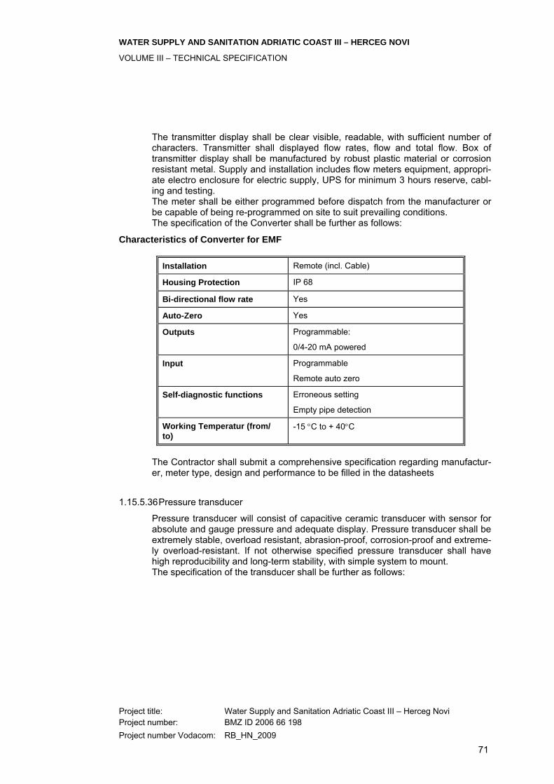
WATER SUPPLY AND SANITATION ADRIATIC COAST III – HERCEG NOVI
VOLUME III – TECHNICAL SPECIFICATION
Project title: Water Supply and Sanitation Adriatic Coast III – Herceg Novi Project number: BMZ ID 2006 66 198 Project number Vodacom: RB_HN_2009
71
The transmitter display shall be clear visible, readable, with sufficient number of characters. Transmitter shall displayed flow rates, flow and total flow. Box of transmitter display shall be manufactured by robust plastic material or corrosion resistant metal. Supply and installation includes flow meters equipment, appropri-ate electro enclosure for electric supply, UPS for minimum 3 hours reserve, cabl-ing and testing. The meter shall be either programmed before dispatch from the manufacturer or be capable of being re-programmed on site to suit prevailing conditions. The specification of the Converter shall be further as follows:
Characteristics of Converter for EMF
Installation Remote (incl. Cable)
Housing Protection IP 68
Bi-directional flow rate Yes
Auto-Zero Yes
Outputs Programmable:
0/4-20 mA powered
Input Programmable
Remote auto zero
Self-diagnostic functions Erroneous setting
Empty pipe detection
Working Temperatur (from/ to)
-15 °C to + 40°C
The Contractor shall submit a comprehensive specification regarding manufactur-er, meter type, design and performance to be filled in the datasheets
1.15.5.36 Pressure transducer
Pressure transducer will consist of capacitive ceramic transducer with sensor for absolute and gauge pressure and adequate display. Pressure transducer shall be extremely stable, overload resistant, abrasion-proof, corrosion-proof and extreme-ly overload-resistant. If not otherwise specified pressure transducer shall have high reproducibility and long-term stability, with simple system to mount. The specification of the transducer shall be further as follows:
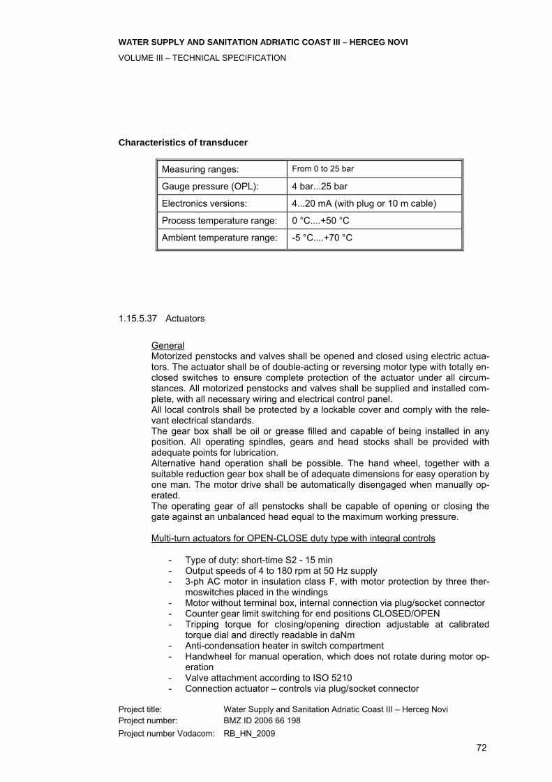
WATER SUPPLY AND SANITATION ADRIATIC COAST III – HERCEG NOVI
VOLUME III – TECHNICAL SPECIFICATION
Project title: Water Supply and Sanitation Adriatic Coast III – Herceg Novi Project number: BMZ ID 2006 66 198 Project number Vodacom: RB_HN_2009
72
Characteristics of transducer
Measuring ranges: From 0 to 25 bar
Gauge pressure (OPL): 4 bar...25 bar
Electronics versions: 4...20 mA (with plug or 10 m cable)
Process temperature range: 0 °C....+50 °C
Ambient temperature range: -5 °C....+70 °C
1.15.5.37 Actuators
General Motorized penstocks and valves shall be opened and closed using electric actua-tors. The actuator shall be of double-acting or reversing motor type with totally en-closed switches to ensure complete protection of the actuator under all circum-stances. All motorized penstocks and valves shall be supplied and installed com-plete, with all necessary wiring and electrical control panel.
All local controls shall be protected by a lockable cover and comply with the rele-vant electrical standards.
The gear box shall be oil or grease filled and capable of being installed in any position. All operating spindles, gears and head stocks shall be provided with adequate points for lubrication.
Alternative hand operation shall be possible. The hand wheel, together with a suitable reduction gear box shall be of adequate dimensions for easy operation by one man. The motor drive shall be automatically disengaged when manually op-erated.
The operating gear of all penstocks shall be capable of opening or closing the gate against an unbalanced head equal to the maximum working pressure. Multi-turn actuators for OPEN-CLOSE duty type with integral controls
- Type of duty: short-time S2 - 15 min - Output speeds of 4 to 180 rpm at 50 Hz supply - 3-ph AC motor in insulation class F, with motor protection by three ther-
moswitches placed in the windings - Motor without terminal box, internal connection via plug/socket connector - Counter gear limit switching for end positions CLOSED/OPEN - Tripping torque for closing/opening direction adjustable at calibrated
torque dial and directly readable in daNm - Anti-condensation heater in switch compartment - Handwheel for manual operation, which does not rotate during motor op-
eration - Valve attachment according to ISO 5210 - Connection actuator – controls via plug/socket connector
WATER SUPPLY AND SANITATION ADRIATIC COAST III – HERCEG NOVI
VOLUME III – TECHNICAL SPECIFICATION
Project title: Water Supply and Sanitation Adriatic Coast III – Herceg Novi Project number: BMZ ID 2006 66 198 Project number Vodacom: RB_HN_2009
73
- Reversing contactors mechanically and electrically interlocked - Local controls with push-buttons OPEN-STOP-CLOSE and lockable op-
eration mode selector switch LOCAL-OFF-REMOTE, indication lights for end positions and fault
- Controls / local controls can be positioned at every 90° - Inputs OPEN-STOP-CLOSE (24 V DC) galvanically isolated via opto-
isolator - Feedback signals for end positions CLOSED/OPEN with potential-free,
gold-plated relay contacts - Feedback signal for operation mode LOCAL/REMOTE with potential-free,
gold-plated relay contacts - Monitor relay with potential-free, gold-plated contacts for collective fault
signal - Automatic phase correction - Permissible ambient temperature – 25 °C to +70 °C, enclosure protection
IP 67, - Corrosion protection KS for installation in aggressive atmosphere with a
moderate pollutant concentration - Wall bracket for mounting of the controls separate from actuator
Multi-turn actuators for modulating duty type with integral controls
- Type of duty: intermittent S4 -25%; max. 1,200 c/h - Output speeds of 4 to 45 rpm at 50 Hz supply - 3-ph AC motor in insulation class F, with motor protection by three ther-
moswitches placed in the windings - Motor without terminal box, internal connection via plug/socket connector - Counter gear limit switching for end positions CLOSED/OPEN - Tripping torque for closing/opening direction adjustable at calibrated
torque dial and directly readable in daNm - Anti-condensation heater in switch compartment - Handwheel for manual operation, which does not rotate during motor op-
eration - Valve attachment according to ISO 5210 - Connection actuator – controls via plug/socket connector - Reversing contactors mechanically and electrically interlocked - Local controls with push-buttons OPEN-STOP-CLOSE and lockable op-
eration mode selector switch LOCAL-OFF-REMOTE, indication lights for end positions and fault
- Controls / local controls can be positioned at every 90° - Inputs OPEN-STOP-CLOSE (24 V DC) galvanically isolated via opto-
isolator - Feedback signals for end positions CLOSED/OPEN with potential-free,
gold-plated relay contacts - Feedback signal for operation mode LOCAL/REMOTE with potential-free,
gold-plated relay contacts - Monitor relay with potential-free, gold-plated contacts for collective fault
signal - Automatic phase correction - Permissible ambient temperature – 25 °C to + 60 °C, enclosure protection
IP 67
WATER SUPPLY AND SANITATION ADRIATIC COAST III – HERCEG NOVI
VOLUME III – TECHNICAL SPECIFICATION
Project title: Water Supply and Sanitation Adriatic Coast III – Herceg Novi Project number: BMZ ID 2006 66 198 Project number Vodacom: RB_HN_2009
74
- Corrosion protection for installation in aggressive atmosphere with a moderate pollutant concentration
- Electronic position transmitter 0/4...20 mA in combination with reduction gearing
- Wall bracket for mounting of the controls separate from actuator
1.15.6 Fans
A: General The equipment shall have the following features: • Fans and associated control units shall satisfy the DIN VDE regulations
within the framework of Equipment Safety Regulations • Pressure / Volumetric flow characteristic curve: The measurements are
made using test stands that comply with DIN EN ISO 5167-1 and DIN 24163 or ISO 5801.
• The fan must be operated within the stable part of the characteristic curve • The fan must operate without speed controls • 8 blade impeller made of anti-static synthetic material, surface resistance
< 109 ohms. • Noiseless impeller of plastic material • The fan must be operated with a protective motor switch, which has been
set for the nominal current. In the case of a short circuit, the protective motor switch must switch the fan off within the temperature rise time stated in the declaration of conformity.
• Type of installation: surface mounted • Fan model with square wall plate • Housing material: sheet steel, galvanized • Protective grille on the intake side, yellow chromated, protection against
accidental contact in accordance with DIN EN 294 B: Motor The equipment shall have the following features: • Asynchronous motor of superior quality standard, designed for continuous
operation (S1), • Motor with ball bearings • Reversing capacity: yes • Type of voltage wave: three-phase AC • Rated voltage: 400V • Frequency: 50 Hz • Maximum air stream temperature: 50 °C • Degree of protection: IP 54 • Temperature class: T1 – T3 • Insulation class F • Explosion proof type for hazardous area zone 1 (if applicable) • Explosion proof terminal boxes, with 2 PG 11 cable screw-connections (if
applicable) • Connecting cable • Overload protection guaranteed by protective motor switch
WATER SUPPLY AND SANITATION ADRIATIC COAST III – HERCEG NOVI
VOLUME III – TECHNICAL SPECIFICATION
Project title: Water Supply and Sanitation Adriatic Coast III – Herceg Novi Project number: BMZ ID 2006 66 198 Project number Vodacom: RB_HN_2009
75
1.15.7 Stand-by emergency power plant
General Electrical Work Generally: Has to be in accordance with the requirements of the related Sections of the Specification. The design of the Stand-by Emergency Power Plant shall guaran-tee, that the biggest consumer will be switched on in a final step. Description of Work: Standby/emergency power plant installation comprises the following:-
One diesel generating set, with associated auxiliaries, exhaust system, start-up system, cooling system, fuel system, batteries and charger etc.
Fuel storage and transfer system.
Instrumentation, protection and control equipment
Manually operated overhead hoist.
Mains failure automatic transfer switch.
Inter-plant cabling and wiring.
Earthing.
Standard: Equipment and component parts are to comply with ISO 3046, IEC 85 and CISPR, or equivalent NEMA, ANSI, IEEE, DIN and VDE Standards and recom-mendations of ABGSM (Association of British Set Manufacturers) where such standards meet with or supersede the ISO and IEC Standards. Equipment Data: Submit full technical data of equipment for approval including, but not limited to, the following:
General description and characteristics of engine-generating set, stan-dards with which components comply, site rating and overload capability, overall efficiency, and fuel and lubricant consumption at 100%, 75%, 50% and 25% of rated load.
Description and operating criteria of engine; type, model, manufacturer,
fuel and lubricating oil types and specific consumption, starting conditions and starting periods from cold to full-load pick-up, governor and response characteristics due to sudden load changes, super-charger, fuel injection system, cooling system and radiator, air filters, fuel filters, oil filters and pumps.

WATER SUPPLY AND SANITATION ADRIATIC COAST III – HERCEG NOVI
VOLUME III – TECHNICAL SPECIFICATION
Project title: Water Supply and Sanitation Adriatic Coast III – Herceg Novi Project number: BMZ ID 2006 66 198 Project number Vodacom: RB_HN_2009
76
Description and operating criteria of generator, exciter and voltage regula-
tor, with loading response and short-circuit characteristics, insulation, cooling and accessories.
Dimensions, weights and forces, mounting methods, vibration protection
etc.
Battery type, make, charge/discharge characteristics, capacity and con-structional features.
Battery charger, method of charging, equalising and trickle charging
Fuel tanks, pipes and accessories; materials and construction.
Exhaust system and silencers; materials and construction.
Control instruments, protection, alarms, cut-outs, indicating lamps, indi-
cating instruments and all other devices or components.
Automatic transfer switch and control gear.
Calculated noise levels in dB(A)at typical points within engine room and at various locations inside and outside.
Routine Tests: Fully assembled plant or equipment is to be tested at the factory, before shipping. Complete performance tests are to be carried out under site simulated conditions, in accordance with the Standards and as described in the Specification. Shop and Construction Drawings: Submit drawings for approval including, but not limited to, the following:
Certified manufacturers' dimensional drawings, templates and installation instructions for equipment and accessories, showing weights and distribu-tion of forces, location and size of cabling (power and control), piping connections to equipment, and other pertinent data.
Plans and elevations of all equipment.
Separate unit wiring diagrams, schematics and interconnecting wiring
diagrams.
Constructional details of bulk fuel storage tanks and daily service fuel tank, including outline drawings showing piping arrangements, connec-tions and dimensions.
Complete execution drawings of associated auxiliaries.
WATER SUPPLY AND SANITATION ADRIATIC COAST III – HERCEG NOVI
VOLUME III – TECHNICAL SPECIFICATION
Project title: Water Supply and Sanitation Adriatic Coast III – Herceg Novi Project number: BMZ ID 2006 66 198 Project number Vodacom: RB_HN_2009
77
Spare Parts: Provide manufacturer's recommended spare parts for 1,000 hours operation of the standby plant. Provide list of manufacturer's spare parts for 2,000 hours op-eration together with current prices. Tools and Instruments: Provide tools and instruments required for normal routine inspection, testing, op-eration and general maintenance, as recommended by the manufacturer. Approved Manufactureres: Obtain generator sets from one of the following : Deutz (Germany) Caterpillar (USA) Oman (USA) Volvo (Sweden) or other equal and approved. Warranty: Provide one (1) year of warranty for equipment specified in this section. Local Representative: Provide evidence that proposed equipment manufacturer has a locally established and authorised organisation which can be called upon for professional advise and maintenance as may be required, and which can immediately supply spare parts to support day to day and emergency maintenance requirements. Failure to sat-isfy the Engineer may disqualify a manufacturer. Obtain an undertaking by the equipment manufacturer and his authorised local representative to provide an annual maintenance contract, available after sub-stantial completion of the work, covering routine service and emergency service by trained employees, and to ensure supply of necessary standard spare parts. Products Generator Set Assembly: Compact package type, with all equipment mounted on one rigid steel bed frame suitable for skidding. Radiator is to be mounted on the set. Design is to permit easy operation, maintenance and repair. Vibration Reduction: Is to be achieved by appropriate design and careful balancing at factory. Com-pact set is to have approved anti-vibration isolators of steel spring or resilient neoprene between rotating equipment and bed-frame, limiting transmission of vi-

WATER SUPPLY AND SANITATION ADRIATIC COAST III – HERCEG NOVI
VOLUME III – TECHNICAL SPECIFICATION
Project title: Water Supply and Sanitation Adriatic Coast III – Herceg Novi Project number: BMZ ID 2006 66 198 Project number Vodacom: RB_HN_2009
78
bration to building to a maximum of 0.04 mm amplitude throughout the operating vibration frequency range. Noise Reduction: Is to be achieved by approved methods at source of noise. The sound level measured at the distance of 1 m around the building and openings / container shall be below than 55 dB(A) for the system of sound-hood and sound measure-ments of the building / container. Cold Starting Engine is to be fully equipped to start and pickup initial load specified at specified minimum ambient temperature. Cold starting aids, such as engine jacket water heater, lubricating oil heater, intake-air heater, oversize standby battery and all devices, accessories, connections, thermostatic switches and off-duty discon-nects with pilot lights and necessary protection, are to be supplemented as rec-ommended by the manufacturer and approved. Equipment Ratings Are indicated in the Particular Specifications. Ratings are to be net continuous output to consumer, excluding fan and any auxiliaries, auxiliary drives and losses, delivered at specified frequency, voltage and power factor and under worst cli-matic conditions on site. Diesel Generator Set Components: Set consists basically of diesel engine, brushless synchronous generator with di-rect flexible coupling to engine and single or parallel control cubicle as required. Governing: Is to be AO to ISO 3046/IV or BS 5514, using electronic type governor with limits of speed control as specified. Starting and Stopping: When in the automatic mode the set is to start and stop automatically by a signal sensed through and auxiliary contact in the load transfer switchgear. The set is to stop, after an adjustable cool-down period (2-30 minutes). Duty: Plant is to reach full speed within 10 seconds from start impulse and accept im-mediately 80% of net rated output (load being mixed, steady and inductive, with motor starting loads. Transient voltage variation is not to exceed 10% under any step-load application for which the system is intended, up to full rated load, recov-ering to within +/-2% within a few cycles.

WATER SUPPLY AND SANITATION ADRIATIC COAST III – HERCEG NOVI
VOLUME III – TECHNICAL SPECIFICATION
Project title: Water Supply and Sanitation Adriatic Coast III – Herceg Novi Project number: BMZ ID 2006 66 198 Project number Vodacom: RB_HN_2009
79
Fault to Start: Should engine fail to start following a start impulse, the system is to come to rest for a few seconds. Two further starting attempts are to be automatically made with intermediate 20 seconds maximum periods of rest. Should the set fail to start after three attempts, an alarm is to sound and a 'start failure' signal illuminate. Hand Operation: Is to be possible for testing or normal operation through a test/manual/off/auto se-lector switch. Regular Exercising: While on 'auto', the set is to start regularly and automatically every week and is to operate for 30 minutes before stopping. Cooling System: Engine is to be water cooled with gear-driven water pumps. System is to be pres-surised, with heavy duty tropical radiator cooled by reverse flow fan. Fan cowl and hand protection guard are to be fitted. Coolant temperature is to be controlled by one or more thermostats as determined by design of system. Radiator is to be sized for continuous performance at 110% rated load at worst operating ambient conditions with a 15° C temperature differential. Radiator is to be non-ferrous metal, incorporating pressure valve, radiator cap and drain cock and with integral expansion tank. Direct acting modulating thermostatic diversion valve is to control engine cooling water temperature. Under normal operation, by-pass is not to be fully closed. Treated or fresh cooling water and anti-corrosion and anti-freeze additives are to be used as recommended by manufacturer for specific conditions of installation. Cooling Airflow: Obstructions in path of cooling air flow (openings, louvers, grilles, mesh, ducts, bends etc.) are not to reduce air flow below that needed at full rated output. Fan and radiator characteristics are to be selected accordingly. Advise if additional booster fans are required and provide necessary control gear for automatic opera-tion. Cylinders: Are to have removable liners. Wet type liners are to have witness hole between line sealing rings of each cylinder for early detection of coolant or oil leakage. Each cylinder has to have a drilled and tapped hole and a valve for connections of pressure indicator. Lubricating Oil System: Pressurised circulating type, using two engine-driven, gear type lubricating oil pumps with full flow filters and replaceable elements and lubricating oil heat ex-changer. Filter system has to have spring loaded by-pass valve to permit oil cir-culation if filters become clogged. Audible and visual alarms are to cut-in when
WATER SUPPLY AND SANITATION ADRIATIC COAST III – HERCEG NOVI
VOLUME III – TECHNICAL SPECIFICATION
Project title: Water Supply and Sanitation Adriatic Coast III – Herceg Novi Project number: BMZ ID 2006 66 198 Project number Vodacom: RB_HN_2009
80
valve starts opening. Lubricating oil cooler must be shell and tube heat ex-changer with water from engine radiator as the cooling medium. Direct acting thermostatic diversion valve has to control oil temperature. Under normal opera-tion by-pass has not to be fully closed. Fuel System: Has to have injection pump and injectors which are easily removable and re-placeable for servicing. Engine has to have integral, gear type, engine driven transfer pump to lift fuel against a head of 2.5 m and supply it through filters to in-jection pump at constant pressure. Fuel filter elements must be easily replace-able. Equipment and Accessories Diesel Engine and Auxiliaries Design: Diesel engine has to be designed for type of load and application required. En-gine and governor have to be selected to meet operating requirements and re-sponse specified. Engine Type: Compression-ignition type with direct solid-injection, turbo-charged for ratings, over 100 kW, water cooled, with air-cooled radiator, 4-stroke cycle, inline or V-type cylinder arrangement, 1,500 rpm, operating on BS 2869 class A diesel oil, suitable for direct coupling to driven machine. Flywheel has to be suitably sized for type of service and constraints specified, and capable to be rotated at 125% of rated speed without failure. Torsional vibration dampers have to be provided. Engine Rating: Has to be such that alternator can deliver net specified continuous rated output, and has to withstand 10% overload for one hour in any period of twelve hours continuous operation at full load, with temperature rise not exceeding rise allowed by the Standards. Accessibility: It has to be possible to:
Remove rocker-box covers without disturbing fuel injection pipes or other components.
Remove and replace pistons and piston rods, liners, big and small end
shells and caps without dismounting engine.
Bar engine over by hand for spill timing check and adjustment.

WATER SUPPLY AND SANITATION ADRIATIC COAST III – HERCEG NOVI
VOLUME III – TECHNICAL SPECIFICATION
Project title: Water Supply and Sanitation Adriatic Coast III – Herceg Novi Project number: BMZ ID 2006 66 198 Project number Vodacom: RB_HN_2009
81
Measuring Instruments: Engine mounted instruments have to include, at least, water temperature gauge, lubricating oil temperature gauge and pressure gauge, tachometer and running time meter. It must be possible to measure, with extra instrumentation, coolant temperature at lower end of radiator, air depression after air filter, air boost and temperature using methods recommended by manufacturer. Instrument ac-cesses have to be normally sealed by threaded blanking caps. Exhaust System: Has to be complete with flanged, bolted, galvanised, seamless steel pipe sec-tions, long sweep elbows, flexible expansion sections, clean-outs, residential si-lencer, wall thimbles and supporting steelwork. Silencer has to be independently supported. Indoor hot exhaust parts have to be insulated with approved insula-tion, not less than 100 mm thick, with anti-condensation overlap and sheet metal covers to protect insulation. Exhaust system has to be designed to reduce back pressure to below maximum specified by the manufacturer, in relation to exhaust pipe length shown on the Drawings. The exhaust pipe outside the building shall be supported vertical up over the building edge at least 1m, with a conic cover wide enough over the outlet of the exhaust chimney pipe to prevent rain from en-tering the pipe. Air Intake System: Plant room has to have heavy duty air-filter of the locker panel, all metal, clean-able, viscous impingement type, complete with duct and frame, as shown on the Drawings. Engine air filter has to be either dry filter with replaceable paper filter elements or oil-bath filter with dipstick and provision for adding oil while engine is running. Filters have to be capable of removing particles 10 microns and larger. Electric Starting System: Engine starting has to be manual by push-button or automatic through control sys-tem at control panel. System has to consist of heavy duty 24 V D.C. starter mo-tor, heavy duty battery and battery charger. Cranking motor and battery have to be rated for cranking the engine when cold and at lowest temperature recorded. Starting pinion has to disengage automatically when engine fires. Storage Battery: Alkaline, sealed-in-plastic type, complete with battery rack and intercell connec-tors. Battery has to have sufficient capacity to provide at least four cranking peri-ods. Battery Charger: To be 25% over-rated, solid state, full-wave rectifier type, adequate to fully re-charge depleted battery in not more than 8 hours and to control rate of charge (providing a high-charge rate to a depleted battery and reducing to a trickle-charge rate when battery is fully charged) automatically. Ammeter has to be pro-vided to indicated charging rate, which has to be adjustable. Battery charger has

WATER SUPPLY AND SANITATION ADRIATIC COAST III – HERCEG NOVI
VOLUME III – TECHNICAL SPECIFICATION
Project title: Water Supply and Sanitation Adriatic Coast III – Herceg Novi Project number: BMZ ID 2006 66 198 Project number Vodacom: RB_HN_2009
82
to be mounted in control cubicle, unless otherwise approved. The charger shall have 2 LED’s signal lamps, one for boost and one for trickle charging positions. Electronic Governer: has to provide isochronous governing, paralleling and load sharing of generator sets. Governor has to have zero percent (isochronous) setting and adjustable droop from zero percent to 10% droop. System has to include power supply unit, magnetic speed pick-up, control module and actuator using fast response D.C. motor drive or equally approved alternative. Governor has to be designed for fast-response and high-precision of speed (frequency) control, automatic paralleling and load-sharing and has to include speed adjustment to +/-5% of normal, while running, and with remote control interface. Frequency deviation under 25% sud-den load change has not to exceed 0.5 Hz, recovering to stable speed condition of +/-0.1 Hz in 0.5 seconds. Governer Overspeed Trip: has to close fuel pump racks automatically in event of engine OVERSPEED. De-vice has to be separate and independent from governing mechanism. Protective System: has to comprise automatic engine shut-down and generator trip with visual and audible alarm in event of overspeed, low lubricating oil pressure, high cooling wa-ter temperature and over cranking. Generator (Alternator): Type: Synchronous, low reactance, high efficiency, revolving field type, with brushless exciter and flexible coupling, sized to pick up effective load without exceeding transient and steady-state voltage deviation limits specified up to its full nominal rating and designed for the performance stipulated in the Specification. It must be a two bearing construction with bearings of the sleeve or sealed ball type. Leads and Cables: Phase leads have to be brought out fully insulated to a terminal cable box of heavy gauge sheet steel, protection IP 44. Control and protection cables have to be brought out to a separate terminal box. Maximum Voltage Difference: Between the three phases at 100% balanced load may not exceed 1%. With un-balanced load up to 30% on one phase at unity power factor and zero load on other phases, the line-to-neutral voltages may not differ more than 5%. Characteristics: number of phases : 3

WATER SUPPLY AND SANITATION ADRIATIC COAST III – HERCEG NOVI
VOLUME III – TECHNICAL SPECIFICATION
Project title: Water Supply and Sanitation Adriatic Coast III – Herceg Novi Project number: BMZ ID 2006 66 198 Project number Vodacom: RB_HN_2009
83
rated voltage, frequency : 400/230 Volts 50 Hz rated power factor : 0.8 winding connection : reconnectable with ends brought out and
fully insulated. unbalanced load current with none of the phase currents exceeding rated current : 30% minimum Overload rotor : 10% nameplate rating for 1 hr every 12
hours, salient pole type, incorporating damping grid.
excitation : brushless, with rotating armature rectifiers
and discharge resistors voltage regulator : automatic, with readily accessible controls
for voltage level. insulation : class H for stator class H for rotor and ex-
citer Both shall be further protected with 100% epoxy impregnation and an over coat of resilient insulating material on end.
enclosure : drip proof and screen protected (IP 23 to
IEC 144). cooling : built-in centrifugal fans. Voltage Regulation: Overall voltage deviation within normal speed variations has to be within limits specified from no-load to full-load, from hot to cold and with load power factor form 0.8 lagging to unity. Regulator has to reduce voltage automatically if load exceeds capacity of generator. Voltage build-up has to be positive and rapid even when full load is suddenly applied. Line-to-line voltage wave-form deviation factor may not exceed +/-5%. Total harmonic content has not to exceed 5% and that of one harmonic not to exceed 2%. Radio interference suppression has to be within the limits set by the Standards, grade (N). Exciter: Armature has to be 3-phase, directly mounted to generator shaft and connected to generator field windings through six solid state, hermetically sealed, silicon rectifi-ers, accessible for maintenance or repair. Exciter has to have field suppression system to eliminate any source of diode failure resulting from high inductive loads and surges. Exciter field windings have to be stationary. Exciter-regulator combi-nation has to maintain output voltage within limits specified for any load up to 110% generator rating and under any sudden load changes specified.

WATER SUPPLY AND SANITATION ADRIATIC COAST III – HERCEG NOVI
VOLUME III – TECHNICAL SPECIFICATION
Project title: Water Supply and Sanitation Adriatic Coast III – Herceg Novi Project number: BMZ ID 2006 66 198 Project number Vodacom: RB_HN_2009
84
Voltage Regulator: Solid state, volts/Hz type, utilising silicon semi-conductor devices in control and power stages, with built-in electro-magnetic interference suppression and de-signed for single or parallel operation. Manual adjustment to +/-5% of regulated voltage level must be possible by a potentiometer at control panel. All compo-nents have to be sealed, moisture and heat resistant, with a suitable environmen-tally protected enclosure. Voltage regulator has to reduce voltage automatically if load exceeds capacity of generator and has to sustain a 3-phase short-circuit cur-rent at the generator terminals for the period for which the short-circuit protection operates and at least for 3 seconds. Voltage regulator power has to be supported by generator voltage and current to maintain excitation field power. Two Position Switch: must be provided for selection of manual or automatic mode of regulated voltage control.
Instrumentation, Protection and Control Equipment: Generating Set Instruments, Protection and Controls: Control relays, sensing equipment, switchgear protective relays and devices and start, stop and shutdown controls have to be provided as necessary for operation specified. Generating set, instruments, protection and controls have to be mounted preferably in one control cubicle. Instruments and Controls: Have to include at least the following: - Digital voltmeter and 7-position selector switch. - Digital ammeter and 4-position selector switch. - Digital frequency meter. - Off/manual/auto duty switch. - Manual start and stop push-buttons. - Kilowatt-hour meter. - Digital Power factor meter. - Digital Service-hour running counter. - Plant exerciser. - Potentiometer for voltage level control. - Speed raise/lower device.

WATER SUPPLY AND SANITATION ADRIATIC COAST III – HERCEG NOVI
VOLUME III – TECHNICAL SPECIFICATION
Project title: Water Supply and Sanitation Adriatic Coast III – Herceg Novi Project number: BMZ ID 2006 66 198 Project number Vodacom: RB_HN_2009
85
- Cool-down setting controls. Illuminated indicator panel with LED’s at least for low oil pressure, high water temperature, over-speed, fail-to-start, generator overload, battery low charge state. Lamp test push-button. Indicating gauge and low level fuel alarm. Battery charger, on/off switch, pilot lights, D.C. Amperemeter. Alarm sounder and rest controls. Anti-condensation heater. Protective Gear: Has to ensure orderly engine stop or shutdown with reset relays, as required for safety and operational reliability, and has to include the following :- Output circuit breaker for over-current and external earth fault protection. Over-voltage protection with voltage and time lag adjustment. Loss-of-field protection. Breaker must be (for ratings up to 800A): moulded case circuit breaker (MCCB) with solid-state trip unit, (electrically tripped by shunt release). For ratings above 800A: power air circuit breaker (PACB) with solid-state trip (electrically operated and electrically tripped by shunt release). Negative phase sequence protection. For generators above 500 kVA provide a restricted earth fault protection, with cur-rent adjustable settings between 0 and 20% of rated current, and time adjustable settings 0.3 seconds. Control and Protective Gear Cubicles: Generator set mounted instrument and/or control cubicles have to be resiliently mounted, preventing transmission of vibration to the components. Separately mounted instrument and control cubicles have to be self-supporting, floor mounted and free-standing. Cubicles have to be sheet steel construction, venti-lated indoor type, vermin and dust-proof, (IP 42 to ICE 144), with lockable hinged doors and instrument panels, separate compartments for control devices, protec-tive relays, circuit breaker(s) and neutral earthing device. Inner and outer sur-faces of steel enclosures have to be cleaned, phosphatized, primed with heavy duty rust inhibiting primer and finished with two coats of enamel. Wiring has to be 600 V, modularly arranged, with connections made at front terminal blocks with no live conductors exposed. Wires have to have approved numbered ferrules at
WATER SUPPLY AND SANITATION ADRIATIC COAST III – HERCEG NOVI
VOLUME III – TECHNICAL SPECIFICATION
Project title: Water Supply and Sanitation Adriatic Coast III – Herceg Novi Project number: BMZ ID 2006 66 198 Project number Vodacom: RB_HN_2009
86
each terminal. Printed circuit plug-in boards, where applicable, have to be of in-dustry standards, accessible and withdrawable, mounted in standard windings. Relays: Front adjustable, sealed type, with dust-tight enclosures, removable covers, test terminal blocks and plugs for testing relay without removal from case. Removal from casing is to automatically short-circuit respective current transformer secon-dary windings. Instruments: must be housed in enamelled metal cases for switchboard flush installation, with scales and markings protected and sealed. Indicating meters must be minimum 76 mm square. Accuracy has to be within 2% unless otherwise specified. Volt-meters and ammeters have to be moving iron type for D.C. measurements. Current Transfomers: Class 2 for measuring and protection. Voltage Transformers: Single phase, dry type, 0.5 accuracy class. kWH-meter: 3-element type for unbalanced 3-phase, 4-wire loads, fitted with 6-digit cyclom-eter.
Fuel Storage and Transfer Storage Tank Capacity: The capacity of the Fuel Storage Tank shall be sufficient for 36 hours of operation under full load, but 2 cubic meters minimum. Steel thickness 6 mm. Tank design has to be double walled. Daytank construction: Closed cylindrical steel, inclined at least 3 degrees from horizontal and fitted with drain plug, inlet and outlet pipe connectors and breather pipe. Tank design has to be double walled. Daytank breather pipe: Has to have replaceable paper air filter or breather caps with air filters. Daytank instruments:

WATER SUPPLY AND SANITATION ADRIATIC COAST III – HERCEG NOVI
VOLUME III – TECHNICAL SPECIFICATION
Project title: Water Supply and Sanitation Adriatic Coast III – Herceg Novi Project number: BMZ ID 2006 66 198 Project number Vodacom: RB_HN_2009
87
Have to include float switch, solenoid valve and dial-type alarm on over-fill and low-level. Daytank filling pumps: Electrically operated, automatically started and stopped, duplex pumps and standby manual pump, installed on piping system between storage tank and one or more daytanks for fuel transfer. Motor has to be totally enclosed, fan-cooled, squirrel-cage induction type, with integrally coupled pump-rotor contained on one base. Pump has to be self-priming type against the specific head shown on the Drawings. Priming plug, sealed and protected bearings and combination starter with thermal overload protection and circuit breaker for short-circuit protection must be provided. Operation has to be interlocked with float switches in daytank. All necessary check valves on piping system have to be provided. Fuel lines: Heavy gauge, black seamless steel, to ISO/R65 or equal, treated internally with corrosion resistant paint and with joints sealed with PTEE tape. Plumber's twine or gasket sealing compound may not be used. Fuel feed line to daytank has to have bypass with stop-cock. Size of fuel return line from daytank to main fuel tank has to be to manufacturer's recommendations. Filling line of main fuel tank has to be at least as fuel-line-size & external diame-ter, entering tank at opposite end to drain plug. Main tank fill and sounding line connections must have hinged, lockable caps with female threaded bottom inlets. Expansion joints: Stainless steel, packless bellows type, suitable for working pressure and tem-perature of service, of same size as pipe on which installed, with screwed ends for pipe sizes not exceeding 50 mm and flanged ends for sizes over 50 mm. Valves Generally: 125 psi steam working pressure rating and 200 psi cold water non-shock pressure rating and type that can be repacked under pressure. Power and Control Equipment: To comply with the specification. Main failure automatic transfer switch (ATS): Floor mounted, galvanised sheet steel cubicle of equal construction to control cu-bicle, comprising two main contactors or circuit breakers and controls necessary for automatic transfer of power supply from normal source to stand-by source, voltage sensing control relay and time delay relays to signal generator start and stop, auxiliary switches and indicating lights etc. as necessary for the required operation of the system.

WATER SUPPLY AND SANITATION ADRIATIC COAST III – HERCEG NOVI
VOLUME III – TECHNICAL SPECIFICATION
Project title: Water Supply and Sanitation Adriatic Coast III – Herceg Novi Project number: BMZ ID 2006 66 198 Project number Vodacom: RB_HN_2009
88
WATER SUPPLY AND SANITATION ADRIATIC COAST III – HERCEG NOVI
VOLUME III – TECHNICAL SPECIFICATION
Project title: Water Supply and Sanitation Adriatic Coast III – Herceg Novi Project number: BMZ ID 2006 66 198 Project number Vodacom: RB_HN_2009
89
Operation: When voltage and/or frequency of any phase drops below an adjustable setting (60% - 90%) of normal supply, for an adjustable period of 1 - 300 seconds, power failure relay has to actuate engine starting control, whilst normal mains contractor must open. After an adjustable period of 0 -10 seconds from sensing stabilised rated voltage and frequency of generator at the ATS, the emergency contactors has to close. Upon restoration of normal mains supply to above 95% of rated voltage and/or frequency, for and adjustable present period of 2 - 60 minutes, emergency contactors must open and normal mains contactors must close. Mechanical and Electrical Interlocks: Have to prevent contactors/circuit breakers from being closed simultaneously at any time. Transfer mechanism has to be powered from the source to which the load is being transferred. Selector Switch: Has to have the following positions : off : both contactors open and remain open. normal : contactors for normal power source closes and remain closed. emergency : contactors for stand-by power source closes and remains closed. auto : automatic transfer as described above. Pilot Lights: Are to indicate which contactors is on. Instruments: Are to include voltmeter and amperemeter with selector switches. Contactors: Must be acc. to IEC 158-1, 3-phase, 4-pole, magnetic type, 600 V rating, capable of interrupting at least ten times rated current inductive or non-inductive loads un-der normal service conditions and have to have replaceable main arcing contacts and arc quenching devices. Contactors have to withstand, without welding or burning of contacts, an inrush current of 20 times normal rating upon closing and the heaviest short-circuit of the system for period required by upstream protective switchgear to operate or a minimum of 3 seconds, whichever is greater. Three N.O. and three N.C. spare contacts have to be provided on each contactors.
WATER SUPPLY AND SANITATION ADRIATIC COAST III – HERCEG NOVI
VOLUME III – TECHNICAL SPECIFICATION
Project title: Water Supply and Sanitation Adriatic Coast III – Herceg Novi Project number: BMZ ID 2006 66 198 Project number Vodacom: RB_HN_2009
90
Circuit Breakers: Used instead of contactors have to provide same functions as a minimum re-quirement and have to be electrically and manually operated, non-automatic type. Wiring: Moisture and heat resistant, silicon rubber insulated, stranded copper conductors, modularly and neatly arranged on master terminal blocks, with suitable numbering strips and appropriate cartridge types fuses where required. Flexible wiring has to be used on all hinged/draw-out components. Connections: Have to be made at a front terminal block with no live metal exposed. Power ca-bles must terminate on fixed insulated copper connectors suitably sized to receive specified cables. Cable glands and gland plates have to be provided. Metal cases: Of instruments, control switches, relays etc. have to be connected by flexible pro-tective conductors, of not less than 2.5 mm2 section, to nearest earthing bar or terminal. Earthing: Earthing bar has to be provided for connection of protective earthing conductors, using set-screw or bolted anti-turn pressure terminations. Ferrules: Wire ends have to be fitted with numbered ferrules of approved type at each ter-mination. Field and Installation Work: Installation: Equipment bases: Ensure that concrete bases and foundations provided for installation of equipment are constructed in accordance with approved shop and construction drawing sand equipment manufacturers' drawings and that holes for fixing bolts and provisions for passage of cables etc. are provided as required. Built-in items: Ensure that equipment supports, fixings and the like, and sleeves for passage of feeders and cables which are to be built into concrete foundations, bases or build-ing structure are provided as and when required and that they are properly in-stalled.

WATER SUPPLY AND SANITATION ADRIATIC COAST III – HERCEG NOVI
VOLUME III – TECHNICAL SPECIFICATION
Project title: Water Supply and Sanitation Adriatic Coast III – Herceg Novi Project number: BMZ ID 2006 66 198 Project number Vodacom: RB_HN_2009
91
Tools: Use only tools recommended by equipment manufacturers for installations, par-ticularly in making connections and adjustments. Supervision: Carry out equipment installation under the direct supervision of a qualified techni-cian, licensed by and trained at the factory. Final adjustments and putting into satisfactory operation have to be made by a specialist delegated by the factory. Generating Set: Install to maintain alignment and minimise engine and generator stresses. Protect instrumentation and control equipment including engine mounted instruments from machine vibration. Mountings and method of mounting have to be as rec-ommended by the manufacturer and approved by the Engineer. Engine Exhaust Piping Has to be slightly sloped away from engine to avoid condensation returning to en-gine and has to have drain plugs or clean-out at lower end as required. Engine hot-air exhaust duct: Install approved canvas duct with metal frames between radiator and louvered opening in wall for radiator exhaust air. Pipe hangers and supports: Fasten securely to building structure with approved masonry expansion bolts, minimum 20 mm diameter and install in accordance with manufacturer's instruc-tions. Inspection and Tests on Site Equipment: Inspect equipment upon delivery to site and report specified any loss or damage to the Engineer. Earthing resistance tests: Have to be carried out to verify specified requirements. Load test: Have to be carried out at low loads to over load conditions, at various power fac-tors. Measurements have to include voltage and frequency deviations and regu-lating time under various step loading conditions, temperature measurements and pressure measurements at various locations, and in accordance with an approved plan under conditions equal to worst site ambient conditions.

WATER SUPPLY AND SANITATION ADRIATIC COAST III – HERCEG NOVI
VOLUME III – TECHNICAL SPECIFICATION
Project title: Water Supply and Sanitation Adriatic Coast III – Herceg Novi Project number: BMZ ID 2006 66 198 Project number Vodacom: RB_HN_2009
92
Tests: Have to include:
Full load test for 8 hours continuous, immediately followed by 10% over-load test, without interruption.
Insulation measurement.
Functional tests for voltage sensing, automatic start and synchronisation,
transfer of load and load-sharing as applicable.
Operation of engine shut-down and alarm signalling and indication, under simulated fault conditions.
Measurement of vibration transmission to building structure.
Load banks: If actual loads are not made available at time of acceptance testing, provide load banks to carry out complete test cycle of the system under loading and switching conditions necessary to prove compliance with the Specification. Piping System: using carbon dioxide or nitrogen from pressurised cylinder, test each system to 1.5 times normal operating pressure. Do not subject equipment, apparatus or de-vices to pressure exceeding prescribed test pressure obtained from nameplate data or from manufacturers' published data. Apply tests before connecting piping to equipment. Remove or disconnect and blank off relief valves, instruments and devices that might be damaged by test pressure. Maintain test pressure on sys-tem for 24 hours during which time there has to be no noticeable drop in pressure. Check for leaks using soap solution. Isolate source of pressure during testing.
1.15.8 Lifting equipment
General Lifting gear and associated equipment shall comply in general with BS 466, DIN EN 13157, BS 3551 and BS 2573 DIN EN 13001-1 suitable for class 2 duties, and the equipment and the installation shall be approved by the National Inspection for Lifting Devices. The assemblies shall be suitable for lifting the heaviest single item of equipment within the working area. The load hook, incorporating a ball swivel joint, shall ex-tend to within 1.0 m of the lowest working level, whilst sufficient headroom shall be allowed below the crane hook to enable the tallest item of machinery to clear the motor floor level by 1.0 m. Travelling Cranes Travelling cranes shall be manually or electrically operated and include travelling bridge, crab and hoist, electrical motor gears and plant where applicable, opera-tion and maintenance instructions and all other necessary items like bolts, buffers, fixings, etc.
WATER SUPPLY AND SANITATION ADRIATIC COAST III – HERCEG NOVI
VOLUME III – TECHNICAL SPECIFICATION
Project title: Water Supply and Sanitation Adriatic Coast III – Herceg Novi Project number: BMZ ID 2006 66 198 Project number Vodacom: RB_HN_2009
93
Cranes, if electrically operated, shall be supplied complete with flat cables on roller suspensions, controls and motorgears giving speeds in both horizontal di-rections of 15/5 m/min. The hoisting speed shall be approximately 2 m/min with crawling speed of 0.2 m/min. Electrical cranes shall be controlled from the floor by a mobile pushbutton master controller movable along with the crab or the hoist to control movements in all di-rections and speeds. The single or double girder crane bridges shall be the underslung type and be fabricated from universal beams or high grade steel plate box section girders which, together with end carriages of rolled steel sections, shall form a single welded fabrication adequately braced and stiffened to give a rigid structure capa-ble of withstanding all loads imposed. Double girder bridge beams shall be fitted with crab rails securely welded to their upper flanges. The flat bottomed crane rails to EN 13674-1:2003+A1:2007 shall be complete with all fixing bolts, holding down bolts, fishplates, end stops, buffers, etc. The crane rails shall be supported on steel supports bolted to columns. Allowance shall be made for expansion of the rails. The end carriages shall be provided with derailment and wheel brake protection, preventing the carriages falling more than 10 mm. The long and cross travel wheels shall be double flanged and be made of forged or cast steel. The rims of the wheels shall be machined accurately to same diame-ters and with a form fitting the rails. The wheels shall be fitted with roller bearings and be at least 250 mm in diameter. The travelling bridge shall be fitted with four buffers as end stops in conjunction with stops at the limits of the travelling. The buffers shall absorb the kinetic energy from the dead load of the crane. The travelling gears and the hoists for electrically operated cranes shall be driven by electric motors fitted with automatic electro-mechanical brakes for the motors and automatic limit switches for the hoists. The brakes shall be the heavy-duty type, which shall engage automatically when the power supply is cut or fails. The motors shall be capable of working continuously at full load for one hour and shall have the enclosure protection form IP 54. Safety devices such as fuses, relays for overloads and limit switches, alarm bells, etc. as well as the main switch for the crane shall be located in a separate cabi-net. This cabinet shall also house the transformers for the control circuits and the fuses. Electrically driven cranes shall have speeds in both horizontal directions of normal 10 m/min. and crawling 1 m/min. The hoisting or lowering speed to be normal 4 m/min. and crawling 0.4 m/min. The rope pulley shall be as specified in BS 466. The crane hook shall be designed for the relevant load and comply with EN 13674-1:2003+A1:2007. A ball swivel device shall be incorporated into the hook as specified above. The gearings shall be totally enclosed in gear boxes and running in oil. The wheel gears may be grease lubricated. The maximum load of the crane shall be marked on the crane with painted figures in the Montenegrin easily readable from the floor. The complete crane shall be painted in accordance with Clause 3.7 surface ‘A’. Before handing over to the Client, the crane shall be tested with a load of 125% of the maximum marked load in accordance with the applicable standard.

WATER SUPPLY AND SANITATION ADRIATIC COAST III – HERCEG NOVI
VOLUME III – TECHNICAL SPECIFICATION
Project title: Water Supply and Sanitation Adriatic Coast III – Herceg Novi Project number: BMZ ID 2006 66 198 Project number Vodacom: RB_HN_2009
94
2 PARTICULAR SPECIFICATIONS MECHANICAL WORKS
The lump sum items specified hereafter and included in the Bill of Quantities are deemed to include for the following works:
(a) shop drawings for the equipment;
(b) production and assembly, at the Contractor’s site;
(c) storage of the equipment , where necessary, at the Contractor’s store;
(d) packing plan for shipment, transportation within Contractor’s home coun-try and to a harbour in Montenegro including the cost of all duties, fees and insurance;
(e) unloading and transportation from the port in Montenegro to the construc-tion site in Montenegro including fees and insurance except custom du-ties;
(f) temporary storage and protection during storage and transport from the storage site to the final position in the works;
(g) erection of the complete equipment and final testing;
(h) delivery of spare parts and reserve materials for 1 year operation;
(i) commissioning, operation of all machine drives and familiarisation of operators with the installations for a period of at least 20 working days;
(j) clearing of the site and reinstatement of works affected by the contractor’s operations;
(k) searching for and rectifying of defaults;
(l) replacement of defective or damaged parts as may be required to hand over the equipment in perfect working conditions.
The Tender Documents shall be accompanied by the completed Proposal Forms and, if deemed necessary, an explanatory description of selected equipment and additional information (e.g. brochures). The plant arrangement is shown in the Tender Drawings, Volume 5. Each Ten-derer may modify the arrangement as required to suit the equipment chosen. The Contractor shall prepare and submit his execution design and shop drawings and specification for the Engineer’s approval before starting production and/or de-livery. The Contractor shall provide and deliver to the Employer, at no extra cost, all spares needed for one year’s operation. The Tenderer shall list the spares pro-posed for the first year of operation in the Proposal Forms. The proposed list is subject to revision during Tender negotiations with the successful Tenderer. Dur-ing the Maintenance Period (12 months after issue of the Taking-Over Certificate) the Contractor shall be responsible for cost free repair and exchange of the failed equipment. The lump sum prices quoted for the various sections of mechanical engineering works are deemed to include for basic maintenance tools as well as for spares and reserve materials required for the first year of operation. The Contractor shall guarantee that all relevant spare parts can be obtained from the manufacturers for a 10 years period.
WATER SUPPLY AND SANITATION ADRIATIC COAST III – HERCEG NOVI
VOLUME III – TECHNICAL SPECIFICATION
Project title: Water Supply and Sanitation Adriatic Coast III – Herceg Novi Project number: BMZ ID 2006 66 198 Project number Vodacom: RB_HN_2009
95
Unless otherwise specified in this Particular Specification, the requirements of the General Specification of Mechanical Works shall apply.
2.1 MECHANICAL WORKS PUMPING STATION IGALO
2.1.1 Pumps
BoQ item C1.1.
The Contractor shall prepare the execution design, supply, install, test and com-mission the complete equipment for the pump station comprising of:
3 submersible pumps (2 operational and 1 stand-by) incl. guide rails, lift-ing chain
duckfoot bend lifting equipment consisting of portable crane, tubular for fixing of the
crane in the pump chamber, hoisting winch with cable min.8,0 m, com-plete unit portable, max weigth 30 kg, capacity of the crane according to the heaviest weight in the pumping station
Installation according to the tender drawings, complete with all fixing,support ma-terials and the installation of all necessary access and safety provisions.
The pumping arrangement shall allow for the following minimum requirements:
Nominal capacity per pump when 2 operating in parallel: 164 l/s (each pump 82 l/s) Nominal manometric head when 2 pumps operating in parallel: 8.98 m
All pipework and built-in plant shall be made of coated mild steel. Manufacture: Flygt or equivalent
2.1.2 Pipework
BoQ item C 1.2
The Contractor shall prepare the execution design, supply, install, test and com-mission the complete equipment for the pump station comprising of:
flushing connections 2” Discharge Pipe work ND 200, incl. bends, wall pieces, reducers, flanges, disman-
tling joints, connection to collector pipe ND 400, mild steel coated, l = approx. 8 m, No. 3
Non Return Valve ND 200 PN 10, Discharge Pipeline, No. 3 Gate Valve ND 200 PN 10, Discharge Pipeline No. 3 Discharge Pipework ND 400 in valve chamber, incl. all fittings like dismantling
joints, branches for ND 200 discharge pipe connection, reducers, wall piece, blind flange, flanges, flanges to main pipe HDPE pressure pipe DIN 500 SDR 11 PE 80, mild steel coated, l = approx. 4 m, No. 1

WATER SUPPLY AND SANITATION ADRIATIC COAST III – HERCEG NOVI
VOLUME III – TECHNICAL SPECIFICATION
Project title: Water Supply and Sanitation Adriatic Coast III – Herceg Novi Project number: BMZ ID 2006 66 198 Project number Vodacom: RB_HN_2009
96
Installation according to the tender drawings, complete with all fixing, support ma-terials and the installation of all necessary access and safety provisions. Pressure surge protection The Contractor shall prepare a pressure surge calculation for the discharge pipe system. Depending on the results of the calculation the Contractor has to decide weather it is required to install relief valves or not. If relief valve are required the contractor shall prepare the execution design, sup-ply, install, test and commission of the complete equipment for the pressure surge protection comprising of:
Relief valves, Manufacture VAG, Air Valve, Hawle or equivalent Diameter according to the calculation Connection to the pressure pipe, consisting of PE shaft with shut off
valve, pipe saddle for HDPE DIN 8074, flanged connections Manhole with ventilation cover and surface box
Installation according to the tender drawings, complete with all fixing,support ma-terials and the installation of all necessary access and safety provisions.
2.1.3 Gates
BoQ item C1.2
The Contractor shall prepare the execution design, supply, install, test and com-mission the complete equipment for the pump station comprising of:
Penstock ND 700 x 700, with spindle and surface box , No. 1 Penstock ND 800 x 800, with spindle and surface box , No. 1
Installation according to the tender drawings, complete with all fixing, support ma-terials and the installation of all necessary access and safety provisions.
2.1.4 Manual coarse bar screen
BoQ item C 1.3
Manual coarse screen for removal of screenings from underground pumping sta-tions. Separation and transport of screenings by hand Design data: Max. flow rate Qmax = 164 l/s Perforation s = 50 mm Width 1.0 m Height 1.8 m Inclination 70° Material stainless steel (1.4571)

WATER SUPPLY AND SANITATION ADRIATIC COAST III – HERCEG NOVI
VOLUME III – TECHNICAL SPECIFICATION
Project title: Water Supply and Sanitation Adriatic Coast III – Herceg Novi Project number: BMZ ID 2006 66 198 Project number Vodacom: RB_HN_2009
97
The channel behind the screens shall be covered with gratings (open mesh floor-ing). The complete gratings and the support structure in material stainless steel (Mat. No. 1.4571). The channel behind the screen has a radius and different width between 1.0 m and 0.7 m. Area 2 m²
2.1.5 Emergency Diesel Generator
BoQ item C 1.4
The contractor shall detailed design, supply, install, test and commission the complete emergency diesel generator set. The back-up (emergency) power generator shall start-up automatically during power failure and switch off when the power supply is resumed. All machines and electrical consumers have to run on the emergency power gen-erator set. Inter alia the following items have to be supplied by the generator set:
- two submersible pumps, one in operation (refer to C1.1.1)
- control and measuring system
The minimum capacity of the generator should be 60 kVA.
Manufacturer: Kirsch or equivalent
2.1.6 Personal Training
BoQ item C 1.5
Staff named by the operator of the plant has to be comprehensively trained for operation of the total system . The training has to include a theoretical part with the general functions of the of-fered components, and a practical part with the ready-installed system. Upon the training’s end the staff has to be able to operate the plant, to perform the mainte-nances and to execute simple repairs on the systems without support of the con-tractor. The behaviour in case of remote control is also to be considered.
2.1.7 Documentation
BoQ item C 1.6
The following documentation has to be delivered (all records in English and Mon-tenegrin language):
WATER SUPPLY AND SANITATION ADRIATIC COAST III – HERCEG NOVI
VOLUME III – TECHNICAL SPECIFICATION
Project title: Water Supply and Sanitation Adriatic Coast III – Herceg Novi Project number: BMZ ID 2006 66 198 Project number Vodacom: RB_HN_2009
98
• Directory of all drawings and further documents • Functional descriptions and specifications of work and services • List of components • Instructions for service • Separate description of the entire safety measures for prevention of malfunc-
tioning • Test records • Installation drawings
2.2 MECHANICAL WORKS PUMPING STATION CENTAR
2.2.1 Pumps
BoQ item C2.1
The Contractor shall prepare the execution design, supply, install, test and com-mission the complete equipment for the pump station comprising of:
3 submersible pumps (2 operational and 1 stand-by) incl. guide rails, lift-ing chain
duckfoot bend lifting equipment consisting of portable crane, tubular for fixing of the
crane in the pump chamber, hoisting winch with cable min.8,0 m, com-plete unit portable, max weigth 30 kg, capacity of the crane according to the heaviest weight in the pumping station
Installation according to the tender drawings, complete with all fixing,support ma-terials and the installation of all necessary access and safety provisions.
The pumping arrangement shall allow for the following minimum requirements:
Nominal capacity per pump when 2 operating in parallel: 224 l/s (each pump 112 l/s) Nominal manometric head when 2 pumps operating in parallel: 8.05 m
All pipework and built-in plant shall be made of coated mild steel. Manufacture: Flygt or equivalent
2.2.2 Pipework
BoQ item C 2.2
The Contractor shall prepare the execution design, supply, install, test and com-mission the complete equipment for the pump station comprising of:

WATER SUPPLY AND SANITATION ADRIATIC COAST III – HERCEG NOVI
VOLUME III – TECHNICAL SPECIFICATION
Project title: Water Supply and Sanitation Adriatic Coast III – Herceg Novi Project number: BMZ ID 2006 66 198 Project number Vodacom: RB_HN_2009
99
flushing connections 2” Discharge Pipe work ND 200, incl. bends, wall pieces, reducers, flanges, disman-
tling joints, connection to collector pipe ND 400, mild steel coated, l = approx. 6 m, No. 3
Non Return Valve ND 200 PN 10, Discharge Pipeline, No. 3 Gate Valve ND 200 PN 10, Discharge Pipeline No. 3 Discharge Pipework ND 400 in valve chamber, incl. all fittings like dismantling
joints, branches for ND 200 discharge pipe connection, reducers, wall piece, blind flange, flanges, flanges to main pipe HDPE pressure pipe DIN 500 SDR 11 PE 80, mild steel coated, l = approx. 4 m, No. 1
Installation according to the tender drawings, complete with all fixing, support ma-terials and the installation of all necessary access and safety provisions. Pressure surge protection The Contractor shall prepare a pressure surge calculation for the discharge pipe system. Depending on the results of the calculation the Contractor has to decide weather it is required to install relief valves or not. If relief valve are required the contractor shall prepare the execution design, sup-ply, install, test and commission of the complete equipment for the pressure surge protection comprising of:
Relief valves, Manufacture VAG, Air Valve, Hawle or equivalent Diameter according to the calculation Connection to the pressure pipe, consisting of PE shaft with shut off
valve, pipe saddle for HDPE DIN 8074, flanged connections Manhole with ventilation cover and surface box
Installation according to the tender drawings, complete with all fixing,support ma-terials and the installation of all necessary access and safety provisions.
2.2.3 Gates
BoQ item C2.2
The Contractor shall prepare the execution design, supply, install, test and com-mission the complete equipment for the pump station comprising of:
penstock ND 800 x 800, with spindle and surface box , No. 2 Installation according to the tender drawings, complete with all fixing, support ma-terials and the installation of all necessary access and safety provisions.
2.2.4 Manual coarse bar screen
BoQ item C 2.3
WATER SUPPLY AND SANITATION ADRIATIC COAST III – HERCEG NOVI
VOLUME III – TECHNICAL SPECIFICATION
Project title: Water Supply and Sanitation Adriatic Coast III – Herceg Novi Project number: BMZ ID 2006 66 198 Project number Vodacom: RB_HN_2009
100
Manual coarse screen for removal of screenings from underground pumping sta-tions. Separation and transport of screenings by hand Design data: Max. flow rate Qmax = 164 l/s Perforation s = 50 mm Width 1.0 m Height 1.8 m Inclination 70° Material stainless steel (1.4571) The channel behind the screens shall be covered with gratings (open mesh floor-ing). The complete gratings and the support structure in material stainless steel (Mat. No. 1.4571). The channel behind the screen has a radius and different width between 1.0 m and 0.7 m. Area 2 m²
2.2.5 Emergency Diesel Generator
BoQ item C 2.4
The contractor shall detailed design, supply, install, test and commission the complete emergency diesel generator set. The back-up (emergency) power generator shall start-up automatically during power failure and switch off when the power supply is resumed. All machines and electrical consumers have to run on the emergency power gen-erator set. Inter alia the following items have to be supplied by the generator set:
- two submersible pumps, one in operation (refer to C2.1.1)
- control and measuring system
The minimum capacity of the generator should be 135 kVA.
Manufacturer: Kirsch or equivalent
2.2.6 Personal Training
BoQ item C 2.5
Staff named by the operator of the plant has to be comprehensively trained for operation of the total system . The training has to include a theoretical part with the general functions of the of-fered components, and a practical part with the ready-installed system. Upon the training’s end the staff has to be able to operate the plant, to perform the mainte-
WATER SUPPLY AND SANITATION ADRIATIC COAST III – HERCEG NOVI
VOLUME III – TECHNICAL SPECIFICATION
Project title: Water Supply and Sanitation Adriatic Coast III – Herceg Novi Project number: BMZ ID 2006 66 198 Project number Vodacom: RB_HN_2009
101
nances and to execute simple repairs on the systems without support of the con-tractor. The behaviour in case of remote control is also to be considered.
2.2.7 Documentation
BoQ item C 2.6
The following documentation has to be delivered (all records in English and Mon-tenegrin language): • Directory of all drawings and further documents • Functional descriptions and specifications of work and services • List of components • Instructions for service • Separate description of the entire safety measures for prevention of malfunc-
tioning • Test records • Installation drawings
2.3 MECHANICAL WORKS PUMPING STATION FORTE MARE
2.3.1 Pumps
BoQ item C3.1
The Contractor shall prepare the execution design, supply, install, test and com-mission the complete equipment for the pump station comprising of:
3 submersible pumps (2 operational and 1 stand-by) incl. guide rails, lift-ing chain
duckfoot bend lifting equipment consisting of portable crane, tubular for fixing of the
crane in the pump chamber, hoisting winch with cable min.8,0 m, com-plete unit portable, max weigth 30 kg, capacity of the crane according to the heaviest weight in the pumping station
Installation according to the tender drawings, complete with all fixing,support ma-terials and the installation of all necessary access and safety provisions.
The pumping arrangement shall allow for the following minimum requirements:
Nominal capacity per pump when 2 operating in parallel: 266 l/s (each pump 133 l/s)
WATER SUPPLY AND SANITATION ADRIATIC COAST III – HERCEG NOVI
VOLUME III – TECHNICAL SPECIFICATION
Project title: Water Supply and Sanitation Adriatic Coast III – Herceg Novi Project number: BMZ ID 2006 66 198 Project number Vodacom: RB_HN_2009
102
Nominal manometric head when 2 pumps operating in parallel: 8.6 m
All pipework and built-in plant shall be made of coated mild steel. Manufacture: Flygt or equivalent
2.3.2 Pipework
BoQ item C 3.2
The Contractor shall prepare the execution design, supply, install, test and com-mission the complete equipment for the pump station comprising of:
flushing connections 2” Discharge Pipe work ND 350, incl. bends, wall pieces, reducers, flanges, disman-
tling joints, wall piece, mild steel coated, l = approx. 8 m, No. 3 Non Return Valve ND 350 PN 10, Discharge Pipeline, No. 3 Gate Valve ND 350 PN 10, Discharge Pipeline No. 3
Installation according to the tender drawings, complete with all fixing, support ma-terials and the installation of all necessary access and safety provisions. Pressure surge protection The Contractor shall prepare a pressure surge calculation for the discharge pipe system. Depending on the results of the calculation the Contractor has to decide weather it is required to install relief valves or not. If relief valve are required the contractor shall prepare the execution design, sup-ply, install, test and commission of the complete equipment for the pressure surge protection comprising of:
Relief valves, Manufacture VAG, Air Valve, Hawle or equivalent Diameter according to the calculation Connection to the pressure pipe, consisting of PE shaft with shut off
valve, pipe saddle for HDPE DIN 8074, flanged connections Manhole with ventilation cover and surface box
Installation according to the tender drawings, complete with all fixing,support ma-terials and the installation of all necessary access and safety provisions.
2.3.3 Gates
BoQ item C 3.2
The Contractor shall prepare the execution design, supply, install, test and com-mission the complete equipment for the pump station comprising of:
penstock ND 800 x 800, with spindle and surface box , No. 2
WATER SUPPLY AND SANITATION ADRIATIC COAST III – HERCEG NOVI
VOLUME III – TECHNICAL SPECIFICATION
Project title: Water Supply and Sanitation Adriatic Coast III – Herceg Novi Project number: BMZ ID 2006 66 198 Project number Vodacom: RB_HN_2009
103
Installation according to the tender drawings, complete with all fixing, support ma-terials and the installation of all necessary access and safety provisions.

WATER SUPPLY AND SANITATION ADRIATIC COAST III – HERCEG NOVI
VOLUME III – TECHNICAL SPECIFICATION
Project title: Water Supply and Sanitation Adriatic Coast III – Herceg Novi Project number: BMZ ID 2006 66 198 Project number Vodacom: RB_HN_2009
104
2.3.4 Manual coarse bar screen
BoQ item C 3.3
Manual coarse screen for removal of screenings from underground pumping sta-tions. Separation and transport of screenings by hand Design data: Max. flow rate Qmax = 164 l/s Perforation s = 50 mm Width 1.0 m Height 1.8 m Inclination 70° Material stainless steel (1.4571) The channel behind the screens shall be covered with gratings (open mesh floor-ing). The complete gratings and the support structure in material stainless steel (Mat. No. 1.4571). The channel behind the screen has a radius and different width between 1.0 m and 0.7 m. Area 5 m²
2.3.5 Emergency Diesel Generator
BoQ item C 3.4
The contractor shall detailed design, supply, install, test and commission the complete emergency diesel generator set. The back-up (emergency) power generator shall start-up automatically during power failure and switch off when the power supply is resumed. All machines and electrical consumers have to run on the emergency power gen-erator set. Inter alia the following items have to be supplied by the generator set:
- two submersible pumps, one in operation (refer to C3.1.1)
- control and measuring system
The minimum capacity of the generator should be 135 kVA.
Manufacturer: Kirsch or equivalent

WATER SUPPLY AND SANITATION ADRIATIC COAST III – HERCEG NOVI
VOLUME III – TECHNICAL SPECIFICATION
Project title: Water Supply and Sanitation Adriatic Coast III – Herceg Novi Project number: BMZ ID 2006 66 198 Project number Vodacom: RB_HN_2009
105
2.3.6 Personal Training
BoQ item C 3.5
Staff named by the operator of the plant has to be comprehensively trained for operation of the total system . The training has to include a theoretical part with the general functions of the of-fered components, and a practical part with the ready-installed system. Upon the training’s end the staff has to be able to operate the plant, to perform the mainte-nances and to execute simple repairs on the systems without support of the con-tractor. The behaviour in case of remote control is also to be considered.
2.3.7 Documentation
BoQ item C 3.6
The following documentation has to be delivered (all records in English and Mon-tenegrin language): • Directory of all drawings and further documents • Functional descriptions and specifications of work and services • List of components • Instructions for service • Separate description of the entire safety measures for prevention of malfunc-
tioning • Test records • Installation drawings
2.4 MECHANICAL WORKS PUMPING STATION SAVINA
2.4.1 Pumps
BoQ item C4.1
The Contractor shall prepare the execution design, supply, install, test and com-mission the complete equipment for the pump station comprising of:
4 submersible pumps (3 operational and 1 stand-by) incl. guide rails, lift-ing chain
duckfoot bend lifting equipment consisting of portable crane, tubular for fixing of the
crane in the pump chamber, hoisting winch with cable min.8,0 m, com-
WATER SUPPLY AND SANITATION ADRIATIC COAST III – HERCEG NOVI
VOLUME III – TECHNICAL SPECIFICATION
Project title: Water Supply and Sanitation Adriatic Coast III – Herceg Novi Project number: BMZ ID 2006 66 198 Project number Vodacom: RB_HN_2009
106
plete unit portable, max weigth 30 kg, capacity of the crane according to the heaviest weight in the pumping station
Installation according to the tender drawings, complete with all fixing,support ma-terials and the installation of all necessary access and safety provisions.
The pumping arrangement shall allow for the following minimum requirements:
Nominal capacity per pump when 3 operating in parallel: 303 l/s (each pump 101 l/s) Nominal manometric head when 3 pumps operating in parallel: 5.1 m
All pipework and built-in plant shall be made of coated mild steel. Manufacture: Flygt or equivalent
2.4.2 Pipework
BoQ item C 4.2
The Contractor shall prepare the execution design, supply, install, test and com-mission the complete equipment for the pump station comprising of:
flushing connections 2” Discharge Pipe work ND 300, incl. bends, wall pieces, reducers, flanges,
dismantling joints, wall piece, mild steel coated, l = approx. 10.0 m, No. 3 Non Return Valve ND 300 PN 10, Discharge Pipeline, No. 3 Gate Valve ND 300 PN 10, Discharge Pipeline No. 3
Installation according to the tender drawings, complete with all fixing, support ma-terials and the installation of all necessary access and safety provisions. Pressure surge protection The Contractor shall prepare a pressure surge calculation for the discharge pipe system. Depending on the results of the calculation the Contractor has to decide weather it is required to install relief valves or not. If relief valve are required the contractor shall prepare the execution design, sup-ply, install, test and commission of the complete equipment for the pressure surge protection comprising of:
Relief valves, Manufacture VAG, Air Valve, Hawle or equivalent Diameter according to the calculation Connection to the pressure pipe, consisting of PE shaft with shut off
valve, pipe saddle for HDPE DIN 8074, flanged connections Manhole with ventilation cover and surface box
WATER SUPPLY AND SANITATION ADRIATIC COAST III – HERCEG NOVI
VOLUME III – TECHNICAL SPECIFICATION
Project title: Water Supply and Sanitation Adriatic Coast III – Herceg Novi Project number: BMZ ID 2006 66 198 Project number Vodacom: RB_HN_2009
107
Installation according to the tender drawings, complete with all fixing,support ma-terials and the installation of all necessary access and safety provisions.
2.4.3 Gates
BoQ item C4.2
The Contractor shall prepare the execution design, supply, install, test and com-mission the complete equipment for the pump station comprising of:
penstock ND 800 x 800, with spindle and surface box , No. 2 Installation according to the tender drawings, complete with all fixing, support ma-terials and the installation of all necessary access and safety provisions.
2.4.4 Manual coarse bar screen
BoQ item C 4.3
Manual coarse screen for removal of screenings from underground pumping sta-tions. Separation and transport of screenings by hand Design data: Max. flow rate Qmax = 164 l/s Perforation s = 50 mm Width 1.0 m Height 1.8 m Inclination 70° Material stainless steel (1.4571) The channel behind the screens shall be covered with gratings (open mesh floor-ing). The complete gratings and the support structure in material stainless steel (Mat. No. 1.4571). The channel behind the screen has a radius and different width between 1.0 m and 0.7 m. Area 5 m²
2.4.5 Emergency Diesel Generator
BoQ item C 4.4
The contractor shall detailed design, supply, install, test and commission the complete emergency diesel generator set. The back-up (emergency) power generator shall start-up automatically during power failure and switch off when the power supply is resumed. All machines and electrical consumers have to run on the emergency power gen-erator set. Inter alia the following items have to be supplied by the generator set:
WATER SUPPLY AND SANITATION ADRIATIC COAST III – HERCEG NOVI
VOLUME III – TECHNICAL SPECIFICATION
Project title: Water Supply and Sanitation Adriatic Coast III – Herceg Novi Project number: BMZ ID 2006 66 198 Project number Vodacom: RB_HN_2009
108
- two submersible pumps, one in operation (refer to C4.1.1)
- control and measuring system
The minimum capacity of the generator should be 100 kVA.
Manufacturer: Kirsch or equivalent
2.4.6 Personal Training
BoQ item C 4.5
Staff named by the operator of the plant has to be comprehensively trained for operation of the total system . The training has to include a theoretical part with the general functions of the of-fered components, and a practical part with the ready-installed system. Upon the training’s end the staff has to be able to operate the plant, to perform the mainte-nances and to execute simple repairs on the systems without support of the con-tractor. The behaviour in case of remote control is also to be considered.
2.4.7 Documentation
BoQ item C 4.6
The following documentation has to be delivered (all records in English and Mon-tenegrin language): • Directory of all drawings and further documents • Functional descriptions and specifications of work and services • List of components • Instructions for service • Separate description of the entire safety measures for prevention of malfunc-
tioning • Test records • Installation drawings
WATER SUPPLY AND SANITATION ADRIATIC COAST III – HERCEG NOVI
VOLUME III – TECHNICAL SPECIFICATION
Project title: Water Supply and Sanitation Adriatic Coast III – Herceg Novi Project number: BMZ ID 2006 66 198 Project number Vodacom: RB_HN_2009
109
2.5 MECHANICAL WORKS PUMPING STATION MELIJINE ROUNDABOUT
2.5.1 Pumps
BoQ item C 5.1
Centrifugal Pumps
The contractor shall prepare the execution design (acc. To his chosen equip-ment), supply, install, test and commission of the complete pump system. The pumping station shall be equipped with three pumps of same capacity. The selected pumps are horizontal centrifugal pump type, designed for dry well instal-lation with saddle mounted motor, with a direct coupled drive. Impeller pumps shall be used with an unaffected free passage of at least 100 mm. Pumps and the impeller shall be cleaned from inside through cleaning ports. In detail each of the pumps shall have the following characteristics and specifica-tion: Nominal capacity per pump when 2 operating in parallel: 574 l/s (each pump 287 l/s) Nominal manometric head when 2 pumps operating in parallel: 22.3 m Manufacturer: KSB or equivalent
Submersible pump
The contractor shall prepare the execution design (acc. To his chosen equip-ment), supply, install, test and commission of the complete pump system. The pumping station shall be equipped with one submersible basement drainage Pump. The pump shall have the following characteristics and specification: Nominal capacity: 10 l/s Nominal manometric head: 10.0 m Manufacturer: KSB or equivalent
2.5.2 Pipework
BoQ item C 5.2
The Contractor shall prepare the execution design, supply, install, test and com-mission the complete equipment for the pump station comprising of:
flushing connections 2”
WATER SUPPLY AND SANITATION ADRIATIC COAST III – HERCEG NOVI
VOLUME III – TECHNICAL SPECIFICATION
Project title: Water Supply and Sanitation Adriatic Coast III – Herceg Novi Project number: BMZ ID 2006 66 198 Project number Vodacom: RB_HN_2009
110
Suction Pipe work ND 500; bend, wall piece, suction pipeline, reducer, connection to the pump, incl. all necessary equipment , like flange con-nections, dismantling joints, mild steel coated, l = approx. 3 m , No. 4
Gate valve ND 500 PN 10, suction pipeline, No. 4 Reducer piece ND 500 / 200, No. 4 Discharge pipe work ND 350, from pumps to main collector pipe, connec-
tion to pumps, incl. all necessary equipment, like dismantling joints, flange connections, bends; mild steel coated, l = approx. 6 m, No. 3
Non Return Valve ND 350 PN 10, Discharge Pipeline, No. 3 Gate Valve ND 350 PN 10, Discharge Pipeline, No. 5 Discharge Pipe work ND 350 - 700 in basement, incl. necessary equip-
ment, like dismantling joints, branches for ND 350 discharge pipe connec-tion, branches for ND 200 air release valve connection, reducers, wall piece, blind flange, flanges, mild steel coated, l = approx. 8 m, No. 1
Gate valve ND 700 PN 10, with electrical actuator, discharge pipeline, No. 1
Gate valve ND 200 PN 10, discharge pipeline,for air release valve, No. 1
Installation according to the tender drawings, complete with all fixing, support ma-terials and the installation of all necessary access and safety provisions.
2.5.3 Coarse Screen and mobile waste container
BoQ item C 5.3
Automatically cleaned screen for removal of screenings from underground pump-ing stations. Design data: Max. flow rate Qmax = 574 l/s Perforation s = 50 mm Total machine length LM = circ. 11.300 mm Screenings discharge height a = circ. 2.000 mm Channel width = 1.500 mm Inclination = 75° All components in touch with the medium of 1.4301/1.4541 stainless steel or equal quality (except fittings, drives and bearings), and acid-treated in a pickling bath. CE safety ensured, i.e. railing or cover for the machine area required. Electrical switchboard and control panel Control panel for wall mounting in compliance with UVV and VDE safety stan-dards. Make: RITTAL/Spangler or equal quality (protection grade: IP 55), painted steel RAL 7035. Complete with all components required for fully automatic operation of the plant. Control units: selector switch (HAND – 0 – AUTO – REVERSE) PLC make SIEMENS or equal quality, type: Elektronik Modul Logo

WATER SUPPLY AND SANITATION ADRIATIC COAST III – HERCEG NOVI
VOLUME III – TECHNICAL SPECIFICATION
Project title: Water Supply and Sanitation Adriatic Coast III – Herceg Novi Project number: BMZ ID 2006 66 198 Project number Vodacom: RB_HN_2009
111
Motor protection switch, fuses, relays, socket-power unit 24 V DC Reset key Selectable times (without changing the PLC program) Hours run meter integrated in control panel door Run-on time of the plant Indication of operation signals, trouble signals, etc. Level control by pneumatic differential water level system (air injection) combined with run-on time Auto reverse dependent on running time Timer for auto start parallel to auto start by level control Adjacent control box without Ex protection For wall mounting, with emergency cutoff button and selector switch, required if central control panel is not mounted immediately adjacent to the machine. Make SIEMENS, plastic material Protection grade IP 54 Incl. electrical and mechanical installation of the adjacent control box Manufacturer: Huber or equivalent Typ: Rake Max 11300x1252x25 or equivalent Mobile waste containers shall be Containers with 4 wheels with a capacity of 1.100 l for comb lifting devices. Material galvanized steel. Dimensions and design according to DIN EN 840. No. of container: 2 The channel in front the screen shall be covered with gratings (open mesh floor-ing). The complete gratings and the support structure in material stainless steel (Mat. No. 1.4571). Area: 10 m²
2.5.4 Emergency Diesel Generator
BoQ item C 5.4
The contractor shall detailed design, supply, install, test and commission the complete emergency diesel generator set. The back-up (emergency) power generator shall start-up automatically during power failure and switch off when the power supply is resumed. All machines and electrical consumers have to run on the emergency power gen-erator set. Inter alia the following items have to be supplied by the generator set:
- two submersible pumps, one in operation (refer to C5.1.1)

WATER SUPPLY AND SANITATION ADRIATIC COAST III – HERCEG NOVI
VOLUME III – TECHNICAL SPECIFICATION
Project title: Water Supply and Sanitation Adriatic Coast III – Herceg Novi Project number: BMZ ID 2006 66 198 Project number Vodacom: RB_HN_2009
112
- control and measuring system
The minimum capacity of the generator should be 350 kVA.
Manufacturer: Kirsch or equivalent
2.5.5 Measurement and Instrumentation
BoQ item C 5.5
The Contractor shall detail design, supply, install, test and commission the MID flow Measurement in the discharge pipe of the pumps.
MID in the Discharge pipe work ND 350, connection to the pipe, incl. all necessary equipment, like flange connections, bends, design flow 0 – 200 l/s, No. 4
Manufacturer: ABB or Endress & Hauser
2.5.6 Pressure Surge Protection
BoQ item C 5.6
The Contractor shall prepare a pressure surge calculation for the discharge pipe system. Depending on the results of the calculation the Contractor has to decide weather it is required to install relief valves or not. If relief valve are required the contractor shall prepare the execution design, sup-ply, install, test and commission of the complete equipment for the pressure surge protection comprising of:
Relief valves, Manufacture VAG, Air Valve, Hawle or equivalent Diameter according to the calculation Connection to the pressure pipe, consisting of PE shaft with shut off
valve, pipe saddle for HDPE DIN 8074, flanged connections Manhole with ventilation cover and surface box
Installation according to the tender drawings, complete with all fixing,support ma-terials and the installation of all necessary access and safety provisions.
2.5.7 Ventilation machinery room
BoQ item C 5.7
The Contractor shall prepare the execution design, supply, install, test and com-mission the complete equipment for the ventilation of the machinery room com-prising of:
WATER SUPPLY AND SANITATION ADRIATIC COAST III – HERCEG NOVI
VOLUME III – TECHNICAL SPECIFICATION
Project title: Water Supply and Sanitation Adriatic Coast III – Herceg Novi Project number: BMZ ID 2006 66 198 Project number Vodacom: RB_HN_2009
113
Ventilator for 4 time air change per hour (ground floor and basement) vent pipe ND 400 down pipe ND 200, No. 2 silencer with all fixing and support material
Installation according to the tender drawings, complete with all fixing, support ma-terials and the installation of all necessary access and safety provisions.
2.5.8 Air pollution control plant
BoQ item C 5.8
The Contractor shall prepare the execution design, supply, install, test and com-mission the complete equipment for the air pollution control plant comprising of:
Ventilator for 4 time air change per hour (screen room) Minimum capacity 1.500 m³/h Minimum filter area 15 m², closed container with covering above the biofil-
ter material, higth of the filter material min. 1,5 m Exhaust fan capacity 1.500 m³/h pipe system ND 300, Material 1.4301, from inside of the screening room
to the blower and from the blower to the filter. with water scrubber unit for pre-conditioning of the waste air, 100 %rel.
humidity after the scrubber incl. control unit Sound hood for the blower, material 1.4301, outdoor installation Connection to the portable water system with all fixing and support material
The whole system shall be in ex-proof construction (inside and outside); exhaust air fan shall be in ex –proofed construction to handle waste air category ex-zone 1. Manufacturer: Tholander or equivalent
2.5.9 Penstocks
BoQ item C 5.9
The Contractor shall prepare the execution design, supply, install, test and com-mission the complete equipment for the pump station comprising of:
penstock ND 1.000 x .1000, with spindle and electrical actuator , No. 3 Installation according to the tender drawings, complete with all fixing, support ma-terials and the installation of all necessary access and safety provisions.
WATER SUPPLY AND SANITATION ADRIATIC COAST III – HERCEG NOVI
VOLUME III – TECHNICAL SPECIFICATION
Project title: Water Supply and Sanitation Adriatic Coast III – Herceg Novi Project number: BMZ ID 2006 66 198 Project number Vodacom: RB_HN_2009
114
2.5.10 Lifting Equipment
BoQ item C 5.10
The Contractor shall prepare the execution design, supply, install, test and com-mission of the complete lifting equipment for the pump station comprising of:
Electric Chain Hoists, No. 2 (ground floor and basement) Compact hoist design with maximum headroom 3-phase power supply Sturdy control pendant and cable Increased safety with electrical upper and lower limit switches delivered
as standard IP55 protection Gentle operation with dual speed motors delivered as standard Durable galvanized load chain Mechanical friction torque limiter Built-in control panel designed for easy access and service Stepless speed control as standard for traveling with a motorized trolley Crane girder, length circ. 6.000 mm / 4.000 mm, No. 2 (ground floor and
basement) Complete Mounting parts for the crane girder
Installation according to the tender drawings, complete with all fixing, support ma-terials and the installation of all necessary access and safety provisions.
2.5.11 Equipment for the Potable Water System
BoQ item C 5.11
The Contractor shall detail design, supply, install, test and commission the entire service water supply system for the pumping station.
The service water supply system shall consist of, but not be limited to:
Service water connection to the network of the city Distribution network of HDPE pipe work (diameter min. DN 50) Service point with tap in the pumping station (basement) Hydrant DN 50 outside of the pumping station (according to DIN 3221)
Generally provision should be made for an extraction point / hydrant and structure that require regular cleaning and flushing during the normal operation and main-tenance of the pumping station. The piping system shall be laid with HDPE pipe pressure class PN 10.
2.5.12 Personal Training
BoQ item C 5.12
Staff named by the operator of the plant has to be comprehensively trained for operation of the total system.
WATER SUPPLY AND SANITATION ADRIATIC COAST III – HERCEG NOVI
VOLUME III – TECHNICAL SPECIFICATION
Project title: Water Supply and Sanitation Adriatic Coast III – Herceg Novi Project number: BMZ ID 2006 66 198 Project number Vodacom: RB_HN_2009
115
The training has to include a theoretical part with the general functions of the of-fered components, and a practical part with the ready-installed system. Upon the training’s end the staff has to be able to operate the plant, to perform the mainte-nances and to execute simple repairs on the systems without support of the con-tractor. The behaviour in case of remote control is also to be considered.
2.5.13 Documentation
BoQ item C 5.13
The following documentation has to be delivered (all records in English and Mon-tenegrin language): • Directory of all drawings and further documents • Functional descriptions and specifications of work and services • List of components • Instructions for service • Separate description of the entire safety measures for prevention of malfunc-
tioning • Test records • Installation drawings
2.6 MECHANICAL WORKS PUMPING STATION BIJELA SHIPYARD
2.6.1 Pumps
BoQ item C6.1
The Contractor shall prepare the execution design, supply, install, test and com-mission the complete equipment for the pump station comprising of:
3 submersible pumps (2 operational and 1 stand-by) incl. guide rails, lift-ing chain
duckfoot bend lifting equipment consisting of portable crane, tubular for fixing of the
crane in the pump chamber, hoisting winch with cable min.8,0 m, com-plete unit portable, max weigth 30 kg, capacity of the crane according to the heaviest weight in the pumping station
Installation according to the tender drawings, complete with all fixing,support ma-terials and the installation of all necessary access and safety provisions.

WATER SUPPLY AND SANITATION ADRIATIC COAST III – HERCEG NOVI
VOLUME III – TECHNICAL SPECIFICATION
Project title: Water Supply and Sanitation Adriatic Coast III – Herceg Novi Project number: BMZ ID 2006 66 198 Project number Vodacom: RB_HN_2009
116
The pumping arrangement shall allow for the following minimum requirements:
Nominal capacity per pump when 2 operating in parallel: 42.4 l/s (each pump 21.2 l/s) Nominal manometric head when 2 pumps operating in parallel: 19.6 m
All pipework and built-in plant shall be made of coated mild steel. Manufacture: Flygt or equivalent
2.6.2 Pipework
BoQ item C 6.2
The Contractor shall prepare the execution design, supply, install, test and com-mission the complete equipment for the pump station comprising of:
flushing connections 2” Discharge Pipe work ND 100, incl. bends, wall pieces, reducers, flanges, disman-
tling joints, connection to collector pipe ND 200, mild steel coated, l = approx. 6 m, No. 3
Non Return Valve ND 100 PN 10, Discharge Pipeline, No. 3 Gate Valve ND 100 PN 10, Discharge Pipeline, incl. protective PVC pipe for
underground assembling, length approx. 2.5 m, incl. taper square adapter and surface box, No. 3
Discharge Pipework ND 200 in valve chamber, incl. all fittings like dismantling joints, branches for ND 100 discharge pipe connection, reducers, wall piece, blind flange, flanges, flanges to main pipe HDPE pressure pipe DIN 250 SDR 11 PE 80, mild steel coated, l = approx. 4 m, No. 1
Installation according to the tender drawings, complete with all fixing, support ma-terials and the installation of all necessary access and safety provisions. Pressure surge protection The Contractor shall prepare a pressure surge calculation for the discharge pipe system. Depending on the results of the calculation the Contractor has to decide weather it is required to install relief valves or not. If relief valve are required the contractor shall prepare the execution design, sup-ply, install, test and commission of the complete equipment for the pressure surge protection comprising of:
Relief valves, Manufacture VAG, Air Valve, Hawle or equivalent Diameter according to the calculation Connection to the pressure pipe, consisting of PE shaft with shut off
valve, pipe saddle for HDPE DIN 8074, flanged connections Manhole with ventilation cover and surface box
Installation according to the tender drawings, complete with all fixing,support ma-terials and the installation of all necessary access and safety provisions.

WATER SUPPLY AND SANITATION ADRIATIC COAST III – HERCEG NOVI
VOLUME III – TECHNICAL SPECIFICATION
Project title: Water Supply and Sanitation Adriatic Coast III – Herceg Novi Project number: BMZ ID 2006 66 198 Project number Vodacom: RB_HN_2009
117
2.6.3 Gates
BoQ item C 6.2
The Contractor shall prepare the execution design, supply, install, test and com-mission the complete equipment for the pump station comprising of:
penstock ND 300, with spindle and surface box , No. 1
Sluice Gate body, frame, gate and stem made of stainless steel (1.4301, grade 304), sealing ring NBR, with extension bar out of stainless steel incl. protective PVC pipe for underground assembling, length approx. 4 m, incl. taper square adapter and surface box, leak proof on both sides up to 4 m WC. Installation according to the tender drawings, complete with all fixing, support ma-terials and the installation of all necessary access and safety provisions.
2.6.4 Manual coarse bar screen
BoQ item C 6.3
Manual coarse screen for removal of screenings from underground pumping sta-tions. Separation and transport of screenings by hand Design data: Max. flow rate Qmax = 164 l/s Perforation s = 50 mm Width 1.0 m Height 1.8 m Inclination 70° Material stainless steel (1.4571) The channel behind the screens shall be covered with gratings (open mesh floor-ing). The complete gratings and the support structure in material stainless steel (Mat. No. 1.4571). The channel behind the screen has a radius and different width between 1.0 m and 0.7 m. Area 2 m²
2.6.5 Emergency Diesel Generator
BoQ item C 6.4
The contractor shall detailed design, supply, install, test and commission the complete emergency diesel generator set.

WATER SUPPLY AND SANITATION ADRIATIC COAST III – HERCEG NOVI
VOLUME III – TECHNICAL SPECIFICATION
Project title: Water Supply and Sanitation Adriatic Coast III – Herceg Novi Project number: BMZ ID 2006 66 198 Project number Vodacom: RB_HN_2009
118
The back-up (emergency) power generator shall start-up automatically during power failure and switch off when the power supply is resumed. All machines and electrical consumers have to run on the emergency power gen-erator set. Inter alia the following items have to be supplied by the generator set:
- two submersible pumps, one in operation (refer to C6.1.1)
- control and measuring system
The minimum capacity of the generator should be 60 kVA.
Manufacturer: Kirsch or equivalent
2.6.6 Personal Training
BoQ item C 6.5
Staff named by the operator of the plant has to be comprehensively trained for operation of the total system . The training has to include a theoretical part with the general functions of the of-fered components, and a practical part with the ready-installed system. Upon the training’s end the staff has to be able to operate the plant, to perform the mainte-nances and to execute simple repairs on the systems without support of the con-tractor. The behaviour in case of remote control is also to be considered.
2.6.7 Documentation
BoQ item C 6.6
The following documentation has to be delivered (all records in English and Mon-tenegrin language): • Directory of all drawings and further documents • Functional descriptions and specifications of work and services • List of components • Instructions for service • Separate description of the entire safety measures for prevention of malfunc-
tioning • Test records • Installation drawings

WATER SUPPLY AND SANITATION ADRIATIC COAST III – HERCEG NOVI
VOLUME III – TECHNICAL SPECIFICATION
Project title: Water Supply and Sanitation Adriatic Coast III – Herceg Novi Project number: BMZ ID 2006 66 198 Project number Vodacom: RB_HN_2009
119
2.7 MECHANICAL WORKS PUMPING STATION BIJELA WEST
2.7.1 Pumps
BoQ item C 7.1
The Contractor shall prepare the execution design, supply, install, test and com-mission the complete equipment for the pump station comprising of:
3 submersible pumps (2 operational and 1 stand-by) incl. guide rails, lift-ing chain
duckfoot bend lifting equipment consisting of portable crane, tubular for fixing of the
crane in the pump chamber, hoisting winch with cable min.8,0 m, com-plete unit portable, max weigth 30 kg, capacity of the crane according to the heaviest weight in the pumping station
Installation according to the tender drawings, complete with all fixing,support ma-terials and the installation of all necessary access and safety provisions.
The pumping arrangement shall allow for the following minimum requirements:
Nominal capacity per pump when 2 operating in parallel: 110 l/s (each pump 55 l/s) Nominal manometric head when 2 pumps operating in parallel: 8.4 m
All pipework and built-in plant shall be made of coated mild steel. Manufacture: Flygt or equivalent
2.7.2 Pipework
BoQ item C 7.2
The Contractor shall prepare the execution design, supply, install, test and com-mission the complete equipment for the pump station comprising of:
flushing connections 2” Discharge Pipe work ND 150, incl. bends, wall pieces, reducers, flanges, disman-
tling joints, connection to collector pipe ND 200, mild steel coated, l = approx. 6 m, No. 3
Non Return Valve ND 150 PN 10, Discharge Pipeline, No. 3 Gate Valve ND 150 PN 10, Discharge Pipeline, with extension bar out of stainless
steel incl. protective PVC pipe for underground assembling, length approx. 2,5 m, incl. taper square adapter and surface box, No. 3
Discharge Pipework ND 300 in valve chamber, incl. all fittings like dismantling joints, branches for ND 150 discharge pipe connection, reducers, wall piece, blind flange, flanges, flanges to main pipe HDPE pressure pipe DIN 250 SDR 11 PE 80, mild steel coated, l = approx. 6 m, No. 1
WATER SUPPLY AND SANITATION ADRIATIC COAST III – HERCEG NOVI
VOLUME III – TECHNICAL SPECIFICATION
Project title: Water Supply and Sanitation Adriatic Coast III – Herceg Novi Project number: BMZ ID 2006 66 198 Project number Vodacom: RB_HN_2009
120
Installation according to the tender drawings, complete with all fixing, support ma-terials and the installation of all necessary access and safety provisions. Pressure surge protection The Contractor shall prepare a pressure surge calculation for the discharge pipe system. Depending on the results of the calculation the Contractor has to decide weather it is required to install relief valves or not. If relief valve are required the contractor shall prepare the execution design, sup-ply, install, test and commission of the complete equipment for the pressure surge protection comprising of:
Relief valves, Manufacture VAG, Air Valve, Hawle or equivalent Diameter according to the calculation Connection to the pressure pipe, consisting of PE shaft with shut off
valve, pipe saddle for HDPE DIN 8074, flanged connections Manhole with ventilation cover and surface box
Installation according to the tender drawings, complete with all fixing,support ma-terials and the installation of all necessary access and safety provisions.
2.7.3 Gates
BoQ item C 7.2
The Contractor shall prepare the execution design, supply, install, test and com-mission the complete equipment for the pump station comprising of:
penstock ND 500, with spindle and surface box , No. 2
Sluice Gate body, frame, gate and stem made of stainless steel (1.4301, grade 304), sealing ring NBR, with extension bar out of stainless steel incl. protective PVC pipe for underground assembling, length approx. 4 m, incl. taper square adapter and surface box, leak proof on both sides up to 4 m WC. Installation according to the tender drawings, complete with all fixing, support ma-terials and the installation of all necessary access and safety provisions.
2.7.4 Manual coarse bar screen
BoQ item C 7.3
Manual coarse screen for removal of screenings from underground pumping sta-tions. Separation and transport of screenings by hand Design data: Max. flow rate Qmax = 164 l/s Perforation s = 50 mm Width 1.0 m
WATER SUPPLY AND SANITATION ADRIATIC COAST III – HERCEG NOVI
VOLUME III – TECHNICAL SPECIFICATION
Project title: Water Supply and Sanitation Adriatic Coast III – Herceg Novi Project number: BMZ ID 2006 66 198 Project number Vodacom: RB_HN_2009
121
Height 1.8 m Inclination 70° Material stainless steel (1.4571) The channel behind the screens shall be covered with gratings (open mesh floor-ing). The complete gratings and the support structure in material stainless steel (Mat. No. 1.4571). The channel behind the screen has a radius and different width between 1.0 m and 0.7 m. Area 2 m²
2.7.5 Emergency Diesel Generator
BoQ item C 7.4
The contractor shall detailed design, supply, install, test and commission the complete emergency diesel generator set. The back-up (emergency) power generator shall start-up automatically during power failure and switch off when the power supply is resumed. All machines and electrical consumers have to run on the emergency power gen-erator set. Inter alia the following items have to be supplied by the generator set:
- two submersible pumps, one in operation (refer to C7.1.1)
- control and measuring system
The minimum capacity of the generator should be 60 kVA.
Manufacturer: Kirsch or equivalent
2.7.6 Personal Training
BoQ item C 7.5
Staff named by the operator of the plant has to be comprehensively trained for operation of the total system . The training has to include a theoretical part with the general functions of the of-fered components, and a practical part with the ready-installed system. Upon the training’s end the staff has to be able to operate the plant, to perform the mainte-nances and to execute simple repairs on the systems without support of the con-tractor. The behaviour in case of remote control is also to be considered.

WATER SUPPLY AND SANITATION ADRIATIC COAST III – HERCEG NOVI
VOLUME III – TECHNICAL SPECIFICATION
Project title: Water Supply and Sanitation Adriatic Coast III – Herceg Novi Project number: BMZ ID 2006 66 198 Project number Vodacom: RB_HN_2009
122
2.7.7 Documentation
BoQ item C 7.6
The following documentation has to be delivered (all records in English and Mon-tenegrin language): • Directory of all drawings and further documents • Functional descriptions and specifications of work and services • List of components • Instructions for service • Separate description of the entire safety measures for prevention of malfunc-
tioning • Test records • Installation drawings
2.8 MECHANICAL WORKS PUMPING STATION DENOVICI
2.8.1 Pumps
BoQ item C 8.1
The Contractor shall prepare the execution design, supply, install, test and com-mission the complete equipment for the pump station comprising of:
3 submersible pumps (2 operational and 1 stand-by) incl. guide rails, lift-ing chain
duckfoot bend lifting equipment consisting of portable crane, tubular for fixing of the
crane in the pump chamber, hoisting winch with cable min.8,0 m, com-plete unit portable, max weigth 30 kg, capacity of the crane according to the heaviest weight in the pumping station
Installation according to the tender drawings, complete with all fixing,support ma-terials and the installation of all necessary access and safety provisions.
The pumping arrangement shall allow for the following minimum requirements:
Nominal capacity per pump when 2 operating in parallel: 177 l/s (each pump 88 l/s) Nominal manometric head when 2 pumps operating in parallel: 7.0 m
All pipework and built-in plant shall be made of coated mild steel. Manufacture: Flygt or equivalent
WATER SUPPLY AND SANITATION ADRIATIC COAST III – HERCEG NOVI
VOLUME III – TECHNICAL SPECIFICATION
Project title: Water Supply and Sanitation Adriatic Coast III – Herceg Novi Project number: BMZ ID 2006 66 198 Project number Vodacom: RB_HN_2009
123
2.8.2 Pipework
BoQ item C 8.2
The Contractor shall prepare the execution design, supply, install, test and com-mission the complete equipment for the pump station comprising of:
flushing connections 2” Discharge Pipe work ND 200, incl. bends, wall pieces, reducers, flanges,
dismantling joints, connection to collector pipe ND 300, mild steel coated, l = approx. 6 m, No. 3
Non Return Valve ND 200 PN 10, Discharge Pipeline, No. 3 Gate Valve ND 200 PN 10, Discharge Pipeline, with extension bar out of
stainless steel incl. protective PVC pipe for underground assembling, length approx. 2,5 m, incl. taper square adapter and surface box, No. 3
Discharge Pipework ND 300 in valve chamber, incl. all fittings like dis-mantling joints, branches for ND 200 discharge pipe connection, reduc-ers, wall piece, blind flange, flanges, mild steel coated, l = approx. 7 m, No. 1
Installation according to the tender drawings, complete with all fixing, support ma-terials and the installation of all necessary access and safety provisions. Pressure surge protection The Contractor shall prepare a pressure surge calculation for the discharge pipe system. Depending on the results of the calculation the Contractor has to decide weather it is required to install relief valves or not. If relief valve are required the contractor shall prepare the execution design, sup-ply, install, test and commission of the complete equipment for the pressure surge protection comprising of:
Relief valves, Manufacture VAG, Air Valve, Hawle or equivalent Diameter according to the calculation Connection to the pressure pipe, consisting of PE shaft with shut off
valve, pipe saddle for HDPE DIN 8074, flanged connections Manhole with ventilation cover and surface box
Installation according to the tender drawings, complete with all fixing,support ma-terials and the installation of all necessary access and safety provisions.
2.8.3 Gates
BoQ item C 8.2
The Contractor shall prepare the execution design, supply, install, test and com-mission the complete equipment for the pump station comprising of:
penstock ND 600, with spindle and surface box , No. 2

WATER SUPPLY AND SANITATION ADRIATIC COAST III – HERCEG NOVI
VOLUME III – TECHNICAL SPECIFICATION
Project title: Water Supply and Sanitation Adriatic Coast III – Herceg Novi Project number: BMZ ID 2006 66 198 Project number Vodacom: RB_HN_2009
124
Sluice Gate body, frame, gate and stem made of stainless steel (1.4301, grade 304), sealing ring NBR, with extension bar out of stainless steel incl. protective PVC pipe for underground assembling, length approx. 4 m, incl. taper square adapter and surface box, leak proof on both sides up to 4 m WC. Installation according to the tender drawings, complete with all fixing, support ma-terials and the installation of all necessary access and safety provisions.
2.8.4 Manual coarse bar screen
BoQ item C 8.3
Manual coarse screen for removal of screenings from underground pumping sta-tions. Separation and transport of screenings by hand Design data: Max. flow rate Qmax = 164 l/s Perforation s = 50 mm Width 1.0 m Height 1.8 m Inclination 70° Material stainless steel (1.4571) The channel behind the screens shall be covered with gratings (open mesh floor-ing). The complete gratings and the support structure in material stainless steel (Mat. No. 1.4571). The channel behind the screen has a radius and different width between 1.0 m and 0.7 m. Area 2 m²
2.8.5 Emergency Diesel Generator
BoQ item C 8.4
The contractor shall detailed design, supply, install, test and commission the complete emergency diesel generator set. The back-up (emergency) power generator shall start-up automatically during power failure and switch off when the power supply is resumed. All machines and electrical consumers have to run on the emergency power gen-erator set. Inter alia the following items have to be supplied by the generator set:
- two submersible pumps, one in operation (refer to C8.1.1)
- control and measuring system

WATER SUPPLY AND SANITATION ADRIATIC COAST III – HERCEG NOVI
VOLUME III – TECHNICAL SPECIFICATION
Project title: Water Supply and Sanitation Adriatic Coast III – Herceg Novi Project number: BMZ ID 2006 66 198 Project number Vodacom: RB_HN_2009
125
The minimum capacity of the generator should be 60 kVA.
Manufacturer: Kirsch or equivalent
2.8.6 Personal Training
BoQ item C 8.5
Staff named by the operator of the plant has to be comprehensively trained for operation of the total system . The training has to include a theoretical part with the general functions of the of-fered components, and a practical part with the ready-installed system. Upon the training’s end the staff has to be able to operate the plant, to perform the mainte-nances and to execute simple repairs on the systems without support of the con-tractor. The behaviour in case of remote control is also to be considered.
2.8.7 Documentation
BoQ item C 8.6
The following documentation has to be delivered (all records in English and Mon-tenegrin language): • Directory of all drawings and further documents • Functional descriptions and specifications of work and services • List of components • Instructions for service • Separate description of the entire safety measures for prevention of malfunc-
tioning • Test records • Installation drawings
2.9 MECHANICAL WORKS PUMPING STATION KUMBOR
2.9.1 Pumps
BoQ item C 9.1
The Contractor shall prepare the execution design, supply, install, test and com-mission the complete equipment for the pump station comprising of:
3 submersible pumps (2 operational and 1 stand-by) incl. guide rails, lift-ing chain
WATER SUPPLY AND SANITATION ADRIATIC COAST III – HERCEG NOVI
VOLUME III – TECHNICAL SPECIFICATION
Project title: Water Supply and Sanitation Adriatic Coast III – Herceg Novi Project number: BMZ ID 2006 66 198 Project number Vodacom: RB_HN_2009
126
duckfoot bend lifting equipment consisting of portable crane, tubular for fixing of the
crane in the pump chamber, hoisting winch with cable min.8,0 m, com-plete unit portable, max weigth 30 kg, capacity of the crane according to the heaviest weight in the pumping station
Installation according to the tender drawings, complete with all fixing,support ma-terials and the installation of all necessary access and safety provisions.
The pumping arrangement shall allow for the following minimum requirements:
Nominal capacity per pump when 2 operating in parallel: 220 l/s (each pump 110 l/s) Nominal manometric head when 2 pumps operating in parallel: 25.9 m
All pipework and built-in plant shall be made of coated mild steel. Manufacture: Flygt or equivalent
2.9.2 Pipework
BoQ item C 9.2
The Contractor shall prepare the execution design, supply, install, test and com-mission the complete equipment for the pump station comprising of:
flushing connections 2” Discharge Pipe work ND 250, incl. bends, wall pieces, reducers, flanges,
dismantling joints, connection to collector pipe ND 200, mild steel coated, l = approx. 6 m, No. 3
Non Return Valve ND 250 PN 10, Discharge Pipeline, No. 3 Gate Valve ND 250 PN 10, Discharge Pipeline, with extension bar out of
stainless steel incl. protective PVC pipe for underground assembling, length approx. 2,5 m, incl. taper square adapter and surface box, No. 3
Discharge Pipework ND 400 in valve chamber, incl. all fittings like dis-mantling joints, branches for ND 250 discharge pipe connection, reduc-ers, wall piece, blind flange, flanges, flanges to main pipe HDPE pressure pipe DIN 500 SDR 11 PE 80, mild steel coated, l = approx. 6 m, No. 1
Installation according to the tender drawings, complete with all fixing, support ma-terials and the installation of all necessary access and safety provisions. Pressure surge protection The Contractor shall prepare a pressure surge calculation for the discharge pipe system. Depending on the results of the calculation the Contractor has to decide weather it is required to install relief valves or not.

WATER SUPPLY AND SANITATION ADRIATIC COAST III – HERCEG NOVI
VOLUME III – TECHNICAL SPECIFICATION
Project title: Water Supply and Sanitation Adriatic Coast III – Herceg Novi Project number: BMZ ID 2006 66 198 Project number Vodacom: RB_HN_2009
127
If relief valve are required the contractor shall prepare the execution design, sup-ply, install, test and commission of the complete equipment for the pressure surge protection comprising of:
Relief valves, Manufacture VAG, Air Valve, Hawle or equivalent Diameter according to the calculation Connection to the pressure pipe, consisting of PE shaft with shut off
valve, pipe saddle for HDPE DIN 8074, flanged connections Manhole with ventilation cover and surface box
Installation according to the tender drawings, complete with all fixing,support ma-terials and the installation of all necessary access and safety provisions.
2.9.3 Gates
BoQ item C9.2
The Contractor shall prepare the execution design, supply, install, test and com-mission the complete equipment for the pump station comprising of:
penstock ND 700, with spindle and surface box , No. 2
Sluice Gate body, frame, gate and stem made of stainless steel (1.4301, grade 304), sealing ring NBR, with extension bar out of stainless steel incl. protective PVC pipe for underground assembling, length approx. 4 m, incl. taper square adapter and surface box, leak proof on both sides up to 4 m WC. Installation according to the tender drawings, complete with all fixing, support ma-terials and the installation of all necessary access and safety provisions.
2.9.4 Manual coarse bar screen
BoQ item C 9.3
Manual coarse screen for removal of screenings from underground pumping sta-tions. Separation and transport of screenings by hand Design data: Max. flow rate Qmax = 164 l/s Perforation s = 50 mm Width 1.0 m Height 1.8 m Inclination 70° Material stainless steel (1.4571) The channel behind the screens shall be covered with gratings (open mesh floor-ing). The complete gratings and the support structure in material stainless steel (Mat. No. 1.4571). The channel behind the screen has a radius and different width between 1.0 m and 0.7 m.
WATER SUPPLY AND SANITATION ADRIATIC COAST III – HERCEG NOVI
VOLUME III – TECHNICAL SPECIFICATION
Project title: Water Supply and Sanitation Adriatic Coast III – Herceg Novi Project number: BMZ ID 2006 66 198 Project number Vodacom: RB_HN_2009
128
Area 2 m²

WATER SUPPLY AND SANITATION ADRIATIC COAST III – HERCEG NOVI
VOLUME III – TECHNICAL SPECIFICATION
Project title: Water Supply and Sanitation Adriatic Coast III – Herceg Novi Project number: BMZ ID 2006 66 198 Project number Vodacom: RB_HN_2009
129
2.9.5 Emergency Diesel Generator
BoQ item C 9.4
The contractor shall detailed design, supply, install, test and commission the complete emergency diesel generator set. The back-up (emergency) power generator shall start-up automatically during power failure and switch off when the power supply is resumed. All machines and electrical consumers have to run on the emergency power gen-erator set. Inter alia the following items have to be supplied by the generator set:
- two submersible pumps, one in operation (refer to C9.1.1)
- control and measuring system
The minimum capacity of the generator should be 350 kVA.
Manufacturer: Kirsch or equivalent
2.9.6 Personal Training
BoQ item C 9.5
Staff named by the operator of the plant has to be comprehensively trained for operation of the total system . The training has to include a theoretical part with the general functions of the of-fered components, and a practical part with the ready-installed system. Upon the training’s end the staff has to be able to operate the plant, to perform the mainte-nances and to execute simple repairs on the systems without support of the con-tractor. The behaviour in case of remote control is also to be considered.
2.9.7 Documentation
BoQ item C 9.6
The following documentation has to be delivered (all records in English and Mon-tenegrin language): • Directory of all drawings and further documents • Functional descriptions and specifications of work and services • List of components • Instructions for service • Separate description of the entire safety measures for prevention of malfunc-
tioning
WATER SUPPLY AND SANITATION ADRIATIC COAST III – HERCEG NOVI
VOLUME III – TECHNICAL SPECIFICATION
Project title: Water Supply and Sanitation Adriatic Coast III – Herceg Novi Project number: BMZ ID 2006 66 198 Project number Vodacom: RB_HN_2009
130
• Test records • Installation drawings
2.10 MECHANICAL WORKS PUMPING STATION KUMBOR NORTH
2.10.1 Pumps
BoQ item C 10.1
The Contractor shall prepare the execution design, supply, install, test and com-mission the complete equipment for the pump station comprising of:
3 submersible pumps (2 operational and 1 stand-by) incl. guide rails, lift-ing chain
duckfoot bend lifting equipment consisting of portable crane, tubular for fixing of the
crane in the pump chamber, hoisting winch with cable min.8,0 m, com-plete unit portable, max weigth 30 kg, capacity of the crane according to the heaviest weight in the pumping station
Installation according to the tender drawings, complete with all fixing,support ma-terials and the installation of all necessary access and safety provisions.
The pumping arrangement shall allow for the following minimum requirements:
Nominal capacity per pump when 2 operating in parallel: 238 l/s (each pump 119 l/s) Nominal manometric head when 2 pumps operating in parallel: 12.20 m
All pipework and built-in plant shall be made of coated mild steel. Manufacture: Flygt or equivalent
2.10.2 Pipework
BoQ item C 10.2
The Contractor shall prepare the execution design, supply, install, test and com-mission the complete equipment for the pump station comprising of:
flushing connections 2” Discharge Pipe work ND 250, incl. bends, wall pieces, reducers, flanges,
dismantling joints, connection to collector pipe ND 200, mild steel coated, l = approx. 6 m, No. 3
Non Return Valve ND 250 PN 10, Discharge Pipeline, No. 3

WATER SUPPLY AND SANITATION ADRIATIC COAST III – HERCEG NOVI
VOLUME III – TECHNICAL SPECIFICATION
Project title: Water Supply and Sanitation Adriatic Coast III – Herceg Novi Project number: BMZ ID 2006 66 198 Project number Vodacom: RB_HN_2009
131
Gate Valve ND 250 PN 10, Discharge Pipeline, with extension bar out of stainless steel incl. protective PVC pipe for underground assembling, length approx. 2,5 m, incl. taper square adapter and surface box, No. 3
Discharge Pipework ND 400 in valve chamber, incl. all fittings like dis-mantling joints, branches for ND 250 discharge pipe connection, reduc-ers, wall piece, blind flange, flanges, flanges to main pipe HDPE pressure pipe DIN 500 SDR 11 PE 80, mild steel coated, l = approx. 6 m, No. 1
Installation according to the tender drawings, complete with all fixing, support ma-terials and the installation of all necessary access and safety provisions. Pressure surge protection The Contractor shall prepare a pressure surge calculation for the discharge pipe system. Depending on the results of the calculation the Contractor has to decide weather it is required to install relief valves or not. If relief valve are required the contractor shall prepare the execution design, sup-ply, install, test and commission of the complete equipment for the pressure surge protection comprising of:
Relief valves, Manufacture VAG, Air Valve, Hawle or equivalent Diameter according to the calculation Connection to the pressure pipe, consisting of PE shaft with shut off
valve, pipe saddle for HDPE DIN 8074, flanged connections Manhole with ventilation cover and surface box
Installation according to the tender drawings, complete with all fixing,support ma-terials and the installation of all necessary access and safety provisions.
2.10.3 Gates
BoQ item C 10.2
The Contractor shall prepare the execution design, supply, install, test and com-mission the complete equipment for the pump station comprising of:
penstock ND 700, with spindle and surface box , No. 2
Sluice Gate body, frame, gate and stem made of stainless steel (1.4301, grade 304), sealing ring NBR, with extension bar out of stainless steel incl. protective PVC pipe for underground assembling, length approx. 4 m, incl. taper square adapter and surface box, leak proof on both sides up to 4 m WC. Installation according to the tender drawings, complete with all fixing, support ma-terials and the installation of all necessary access and safety provisions.
WATER SUPPLY AND SANITATION ADRIATIC COAST III – HERCEG NOVI
VOLUME III – TECHNICAL SPECIFICATION
Project title: Water Supply and Sanitation Adriatic Coast III – Herceg Novi Project number: BMZ ID 2006 66 198 Project number Vodacom: RB_HN_2009
132
2.10.4 Manual coarse bar screen
BoQ item C 10.3
Manual coarse screen for removal of screenings from underground pumping sta-tions. Separation and transport of screenings by hand Design data: Max. flow rate Qmax = 164 l/s Perforation s = 50 mm Width 1.1 m Height 1.5 m Inclination 65° Material stainless steel (1.4571) The channel behind the screens shall be covered with gratings (open mesh floor-ing). The complete gratings and the support structure in material stainless steel (Mat. No. 1.4571). The channel behind the screen has a radius and different width between 1.0 m and 0.7 m. Area 2 m²
2.10.5 Emergency Diesel Generator
BoQ item C 10.4
The contractor shall detailed design, supply, install, test and commission the complete emergency diesel generator set. The back-up (emergency) power generator shall start-up automatically during power failure and switch off when the power supply is resumed. All machines and electrical consumers have to run on the emergency power gen-erator set. Inter alia the following items have to be supplied by the generator set:
- two submersible pumps, one in operation (refer to C10.1.1)
- control and measuring system
The minimum capacity of the generator should be 180 kVA.
Manufacturer: Kirsch or equivalent
2.10.6 Personal Training
BoQ item C 10.5
WATER SUPPLY AND SANITATION ADRIATIC COAST III – HERCEG NOVI
VOLUME III – TECHNICAL SPECIFICATION
Project title: Water Supply and Sanitation Adriatic Coast III – Herceg Novi Project number: BMZ ID 2006 66 198 Project number Vodacom: RB_HN_2009
133
Staff named by the operator of the plant has to be comprehensively trained for operation of the total system. The training has to include a theoretical part with the general functions of the of-fered components, and a practical part with the ready-installed system. Upon the training’s end the staff has to be able to operate the plant, to perform the mainte-nances and to execute simple repairs on the systems without support of the con-tractor. The behaviour in case of remote control is also to be considered.
2.10.7 Documentation
BoQ item C 10.6
The following documentation has to be delivered (all records in English and Mon-tenegrin language): • Directory of all drawings and further documents • Functional descriptions and specifications of work and services • List of components • Instructions for service • Separate description of the entire safety measures for prevention of malfunc-
tioning • Test records • Installation drawings
2.11 MECHANICAL WORKS PUMPING STATION ZMIJICE
2.11.1 Pumps
BoQ item C11.1
The Contractor shall prepare the execution design, supply, install, test and com-mission the complete equipment for the pump station comprising of:
3 submersible pumps (2 operational and 1 stand-by) incl. guide rails, lift-ing chain
duckfoot bend lifting equipment consisting of portable crane, tubular for fixing of the
crane in the pump chamber, hoisting winch with cable min.8,0 m, com-plete unit portable, max weigth 30 kg, capacity of the crane according to the heaviest weight in the pumping station
Installation according to the tender drawings, complete with all fixing,support ma-terials and the installation of all necessary access and safety provisions.

WATER SUPPLY AND SANITATION ADRIATIC COAST III – HERCEG NOVI
VOLUME III – TECHNICAL SPECIFICATION
Project title: Water Supply and Sanitation Adriatic Coast III – Herceg Novi Project number: BMZ ID 2006 66 198 Project number Vodacom: RB_HN_2009
134
WATER SUPPLY AND SANITATION ADRIATIC COAST III – HERCEG NOVI
VOLUME III – TECHNICAL SPECIFICATION
Project title: Water Supply and Sanitation Adriatic Coast III – Herceg Novi Project number: BMZ ID 2006 66 198 Project number Vodacom: RB_HN_2009
135
The pumping arrangement shall allow for the following minimum requirements:
Nominal capacity per pump when 2 operating in parallel: 256 l/s (each pump 128 l/s) Nominal manometric head when 2 pumps operating in parallel: 17.00 m
All pipework and built-in plant shall be made of coated mild steel. Manufacture: Flygt or equivalent
2.11.2 Pipework
BoQ item C 11.2
The Contractor shall prepare the execution design, supply, install, test and com-mission the complete equipment for the pump station comprising of:
flushing connections 2” Discharge Pipe work ND 250, incl. bends, wall pieces, reducers, flanges,
dismantling joints, connection to collector pipe ND 200, mild steel coated, l = approx. 6 m, No. 3
Non Return Valve ND 250 PN 10, Discharge Pipeline, No. 3 Gate Valve ND 250 PN 10, Discharge Pipeline, with extension bar out of
stainless steel incl. protective PVC pipe for underground assembling, length approx. 2,5 m, incl. taper square adapter and surface box, No. 3
Discharge Pipework ND 400 in valve chamber, incl. all fittings like dis-mantling joints, branches for ND 250 discharge pipe connection, reduc-ers, wall piece, blind flange, flanges, flanges to main pipe HDPE pressure pipe DIN 500 SDR 11 PE 80, mild steel coated, l = approx. 6 m, No. 1
Installation according to the tender drawings, complete with all fixing, support ma-terials and the installation of all necessary access and safety provisions. Pressure surge protection The Contractor shall prepare a pressure surge calculation for the discharge pipe system. Depending on the results of the calculation the Contractor has to decide weather it is required to install relief valves or not. If relief valve are required the contractor shall prepare the execution design, sup-ply, install, test and commission of the complete equipment for the pressure surge protection comprising of:
Relief valves, Manufacture VAG, Air Valve, Hawle or equivalent Diameter according to the calculation Connection to the pressure pipe, consisting of PE shaft with shut off
valve, pipe saddle for HDPE DIN 8074, flanged connections Manhole with ventilation cover and surface box

WATER SUPPLY AND SANITATION ADRIATIC COAST III – HERCEG NOVI
VOLUME III – TECHNICAL SPECIFICATION
Project title: Water Supply and Sanitation Adriatic Coast III – Herceg Novi Project number: BMZ ID 2006 66 198 Project number Vodacom: RB_HN_2009
136
Installation according to the tender drawings, complete with all fixing,support ma-terials and the installation of all necessary access and safety provisions.
2.11.3 Gates
BoQ item C11.2
The Contractor shall prepare the execution design, supply, install, test and com-mission the complete equipment for the pump station comprising of:
penstock ND 700, with spindle and surface box , No. 1
Sluice Gate body, frame, gate and stem made of stainless steel (1.4301, grade 304), sealing ring NBR, with extension bar out of stainless steel incl. protective PVC pipe for underground assembling, length approx. 4 m, incl. taper square adapter and surface box, leak proof on both sides up to 4 m WC. Installation according to the tender drawings, complete with all fixing, support ma-terials and the installation of all necessary access and safety provisions.
2.11.4 Manual coarse bar screen
BoQ item C 11.3
Manual coarse screen for removal of screenings from underground pumping sta-tions. Separation and transport of screenings by hand Design data: Max. flow rate Qmax = 164 l/s Perforation s = 50 mm Width 1.1 m Height 1.5 m Inclination 65° Material stainless steel (1.4571) The channel behind the screens shall be covered with gratings (open mesh floor-ing). The complete gratings and the support structure in material stainless steel (Mat. No. 1.4571). The channel behind the screen has a radius and different width between 1.0 m and 0.7 m. Area 2 m²
2.11.5 Emergency Diesel Generator
BoQ item C 11.4
The contractor shall detailed design, supply, install, test and commission the complete emergency diesel generator set.
WATER SUPPLY AND SANITATION ADRIATIC COAST III – HERCEG NOVI
VOLUME III – TECHNICAL SPECIFICATION
Project title: Water Supply and Sanitation Adriatic Coast III – Herceg Novi Project number: BMZ ID 2006 66 198 Project number Vodacom: RB_HN_2009
137
The back-up (emergency) power generator shall start-up automatically during power failure and switch off when the power supply is resumed. All machines and electrical consumers have to run on the emergency power gen-erator set. Inter alia the following items have to be supplied by the generator set:
- two submersible pumps, one in operation (refer to C11.1.1)
- control and measuring system
The minimum capacity of the generator should be 180 kVA.
Manufacturer: Kirsch or equivalent
2.11.6 Personal Training
BoQ item C 11.5
Staff named by the operator of the plant has to be comprehensively trained for operation of the total system . The training has to include a theoretical part with the general functions of the of-fered components, and a practical part with the ready-installed system. Upon the training’s end the staff has to be able to operate the plant, to perform the mainte-nances and to execute simple repairs on the systems without support of the con-tractor. The behaviour in case of remote control is also to be considered.
2.11.7 Documentation
BoQ item C 11.6
The following documentation has to be delivered (all records in English and Mon-tenegrin language): • Directory of all drawings and further documents • Functional descriptions and specifications of work and services • List of components • Instructions for service • Separate description of the entire safety measures for prevention of malfunc-
tioning • Test records • Installation drawings

WATER SUPPLY AND SANITATION ADRIATIC COAST III – HERCEG NOVI
VOLUME III – TECHNICAL SPECIFICATION
Project title: Water Supply and Sanitation Adriatic Coast III – Herceg Novi Project number: BMZ ID 2006 66 198 Project number Vodacom: RB_HN_2009
138
2.12 MECHANICAL WORKS PUMPING STATION ZELENIKA
2.12.1 Pumps
BoQ item C12.1
The Contractor shall prepare the execution design, supply, install, test and com-mission the complete equipment for the pump station comprising of:
4 submersible pumps (3 operational and 1 stand-by) incl. guide rails, lift-ing chain
duckfoot bend lifting equipment consisting of portable crane, tubular for fixing of the
crane in the pump chamber, hoisting winch with cable min.8,0 m, com-plete unit portable, max weigth 30 kg, capacity of the crane according to the heaviest weight in the pumping station
Installation according to the tender drawings, complete with all fixing,support ma-terials and the installation of all necessary access and safety provisions.
The pumping arrangement shall allow for the following minimum requirements:
Nominal capacity per pump when 3 operating in parallel: 299 l/s (each pump 100 l/s) Nominal manometric head when 2 pumps operating in parallel: 16.00 m
All pipework and built-in plant shall be made of coated mild steel. Manufacture: Flygt or equivalent
2.12.2 Pipework
BoQ item C 12.2
The Contractor shall prepare the execution design, supply, install, test and com-mission the complete equipment for the pump station comprising of:
flushing connections 2” Discharge Pipe work ND 250, incl. bends, wall pieces, reducers, flanges,
dismantling joints, connection to collector pipe ND 200, mild steel coated, l = approx. 6 m, No. 4
Non Return Valve ND 250 PN 10, Discharge Pipeline, No. 4 Gate Valve ND 250 PN 10, Discharge Pipeline, with extension bar out of
stainless steel incl. protective PVC pipe for underground assembling, length approx. 1,5 m, incl. taper square adapter and surface box , No. 4
Discharge Pipework ND 500 in valve chamber, incl. all fittings like dis-mantling joints, branches for ND 250 discharge pipe connection, reduc-ers, wall piece, blind flange, flanges, flanges to main pipe HDPE pressure pipe DIN 630 SDR 11 PE 80, mild steel coated, l = approx. 5 m, No. 1

WATER SUPPLY AND SANITATION ADRIATIC COAST III – HERCEG NOVI
VOLUME III – TECHNICAL SPECIFICATION
Project title: Water Supply and Sanitation Adriatic Coast III – Herceg Novi Project number: BMZ ID 2006 66 198 Project number Vodacom: RB_HN_2009
139
Installation according to the tender drawings, complete with all fixing, support ma-terials and the installation of all necessary access and safety provisions. Pressure surge protection The Contractor shall prepare a pressure surge calculation for the discharge pipe system. Depending on the results of the calculation the Contractor has to decide weather it is required to install relief valves or not. If relief valve are required the contractor shall prepare the execution design, sup-ply, install, test and commission of the complete equipment for the pressure surge protection comprising of:
Relief valves, Manufacture VAG, Air Valve, Hawle or equivalent Diameter according to the calculation Connection to the pressure pipe, consisting of PE shaft with shut off
valve, pipe saddle for HDPE DIN 8074, flanged connections Manhole with ventilation cover and surface box No. of valves min. 4
Installation according to the tender drawings, complete with all fixing,support ma-terials and the installation of all necessary access and safety provisions.
2.12.3 Gates
BoQ item C12.2
The Contractor shall prepare the execution design, supply, install, test and com-mission the complete equipment for the pump station comprising of:
penstock ND 700, with spindle and surface box , No. 1
Sluice Gate body, frame, gate and stem made of stainless steel (1.4301, grade 304), sealing ring NBR, with extension bar out of stainless steel incl. protective PVC pipe for underground assembling, length approx. 4 m, incl. taper square adapter and surface box, leak proof on both sides up to 4 m WC. Installation according to the tender drawings, complete with all fixing, support ma-terials and the installation of all necessary access and safety provisions.
2.12.4 Manual coarse bar screen
BoQ item C 12.3
Manual coarse screen for removal of screenings from underground pumping sta-tions. Separation and transport of screenings by hand Design data: Max. flow rate Qmax = 164 l/s Perforation s = 50 mm

WATER SUPPLY AND SANITATION ADRIATIC COAST III – HERCEG NOVI
VOLUME III – TECHNICAL SPECIFICATION
Project title: Water Supply and Sanitation Adriatic Coast III – Herceg Novi Project number: BMZ ID 2006 66 198 Project number Vodacom: RB_HN_2009
140
Width 1.1 m Height 1.5 m Inclination 65° Material stainless steel (1.4571) The channel behind the screens shall be covered with gratings (open mesh floor-ing). The complete gratings and the support structure in material stainless steel (Mat. No. 1.4571). The channel behind the screen has a radius and different width between 1.0 m and 0.7 m. Area 2 m²
2.12.5 Emergency Diesel Generator
BoQ item C 12.4
The contractor shall detailed design, supply, install, test and commission the complete emergency diesel generator set. The back-up (emergency) power generator shall start-up automatically during power failure and switch off when the power supply is resumed. All machines and electrical consumers have to run on the emergency power gen-erator set. Inter alia the following items have to be supplied by the generator set:
- two submersible pumps, one in operation (refer to C12.1.1)
- control and measuring system
The minimum capacity of the generator should be 180 kVA.
Manufacturer: Kirsch or equivalent
2.12.6 Personal Training
BoQ item C 12.5
Staff named by the operator of the plant has to be comprehensively trained for operation of the total system . The training has to include a theoretical part with the general functions of the of-fered components, and a practical part with the ready-installed system. Upon the training’s end the staff has to be able to operate the plant, to perform the mainte-nances and to execute simple repairs on the systems without support of the con-tractor. The behaviour in case of remote control is also to be considered.
WATER SUPPLY AND SANITATION ADRIATIC COAST III – HERCEG NOVI
VOLUME III – TECHNICAL SPECIFICATION
Project title: Water Supply and Sanitation Adriatic Coast III – Herceg Novi Project number: BMZ ID 2006 66 198 Project number Vodacom: RB_HN_2009
141
2.12.7 Documentation
BoQ item C 12.6
The following documentation has to be delivered (all records in English and Mon-tenegrin language): • Directory of all drawings and further documents • Functional descriptions and specifications of work and services • List of components • Instructions for service • Separate description of the entire safety measures for prevention of malfunc-
tioning • Test records • Installation drawings
2.13 MECHANICAL WORKS PUMPING STATION MELJINE OLD
2.13.1 Pumps
BoQ item C 13.1
The Contractor shall prepare the execution design, supply, install, test and com-mission the complete equipment for the pump station comprising of:
2 submersible pumps (1 operational and 1 stand-by) incl. guide rails, lift-ing chain
duckfoot bend lifting equipment consisting of portable crane, tubular for fixing of the
crane in the pump chamber, hoisting winch with cable min.8,0 m, com-plete unit portable, max weigth 30 kg, capacity of the crane according to the heaviest weight in the pumping station
Installation according to the tender drawings, complete with all fixing,support ma-terials and the installation of all necessary access and safety provisions.
The pumping arrangement shall allow for the following minimum requirements:
1 operational pump and 1 stand-by unit of the same size.
All pipework and built-in plant shall be made of coated mild steel.
In detail each of the pumps shall have the following characteristics and specifica-tion:
Nominal capacity per pump: 15 l/s

WATER SUPPLY AND SANITATION ADRIATIC COAST III – HERCEG NOVI
VOLUME III – TECHNICAL SPECIFICATION
Project title: Water Supply and Sanitation Adriatic Coast III – Herceg Novi Project number: BMZ ID 2006 66 198 Project number Vodacom: RB_HN_2009
142
Nominal manometric head approx.: 10.56 m Manufacture: Flygt or equivalent
2.13.2 Pipework
BoQ item C 13.2
The Contractor shall prepare the execution design, supply, install, test and com-mission the complete equipment for the pump station comprising of:
flushing connections 2” Discharge Pipework ND 100, incl. bends, wall pieces, flanges, dismantling
joints, connection to collector pipe ND 100, mild steel coated, l = approx. 10 m, No 2
Non Return Valve ND 100 PN 10, Discharge Pipeline, No. 2 Gate Valve ND 100 PN 10, Discharge Pipeline, No. 2 Discharge Pipework ND 100 in valve chamber, incl. all fittings like dis-
mantling joints, branches for ND 100 discharge pipe conenction, wall piece, blind flange, flanges, flanges to main pipe HDPE pressure pipe DIN 125 SDR 11 PE 80, mild steel coated, l = approx. 10 m, No.1
flushing connections 2”, No.2 Pressure surge protection The Contractor shall prepare a pressure surge calculation for the discharge pipe system. Depending on the results of the calculation the Contractor has to decide weather it is required to install relief valves or not. If relief valve are required the contractor shall prepare the execution design, sup-ply, install, test and commission of the complete equipment for the pressure surge protection comprising of:
Relief valves, Manufacture VAG, Air Valve, Hawle or equivalent Diameter according to the calculation Connection to the pressure pipe, consisting of PE shaft with shut off
valve, pipe saddle for HDPE DIN 8074, flanged connections Manhole with ventilation cover and surface box
Installation according to the tender drawings, complete with all fixing,support ma-terials and the installation of all necessary access and safety provisions.
2.13.3 Emergency Diesel Generator
BoQ item C 13.3
The contractor shall detailed design, supply, install, test and commission the complete emergency diesel generator set. The back-up (emergency) power generator shall start-up automatically during power failure and switch off when the power supply is resumed.

WATER SUPPLY AND SANITATION ADRIATIC COAST III – HERCEG NOVI
VOLUME III – TECHNICAL SPECIFICATION
Project title: Water Supply and Sanitation Adriatic Coast III – Herceg Novi Project number: BMZ ID 2006 66 198 Project number Vodacom: RB_HN_2009
143
All machines and electrical consumers have to run on the emergency power gen-erator set. Inter alia the following items have to be supplied by the generator set:
- two sumersible pumps, one in operation (refer to C13.1.1)
- control and measuring system
The minimum capacity of the generator should be 60 kVA.
Manufacturer: Kirsch or equivalent
2.13.4 Personal Training
BoQ item C 13.4
Staff named by the operator of the plant has to be comprehensively trained for operation of the total system . The training has to include a theoretical part with the general functions of the of-fered components, and a practical part with the ready-installed system. Upon the training’s end the staff has to be able to operate the plant, to perform the mainte-nances and to execute simple repairs on the systems without support of the con-tractor. The behaviour in case of remote control is also to be considered.
2.13.5 Documentation
BoQ item C 13.5
The following documentation has to be delivered (all records in English and Mon-tenegrin language): • Directory of all drawings and further documents • Functional descriptions and specifications of work and services • List of components • Instructions for service • Separate description of the entire safety measures for prevention of malfunc-
tioning • Test records • Installation drawings
