mechanical & lighting requirements of the 2012 iecc · heating and cooling load calculations...
TRANSCRIPT
1
Mechanical & Lighting Requirements of the 2012 IECC
Commercial Workshop 2

2
Introductions
Stephen Johnson
Project email:
Code officials
Name
Municipality
Status of Commercial Codes

3
Overview
Project funded by the Missouri Department of Natural Resources (MDNR) with American Recovery and Reinvestment Act of 2009 (ARRA) funding.
4 Locations and Webinars:
• St. Louis (December 1st – 2nd)
• Springfield (December 5th – 6th)
• Kansas City (January 24th – 25th)
• Columbia (February 27th)
Objective of the Workshop: Work with municipalities and counties across the state to identify opportunities to adopt or enhance compliance with the 2009 or 2012 International Energy Conservation Code (IECC) at a local level.

4
Agenda
Topic Approx. Time
Introduction 10 minutes
Mechanical requirements 55 minutes
Lighting requirements 40 minutes
Additional Efficiency Package 10 minutes
Summary 5 minutes
Total Time 2 hours

5
Some Important Points
Overall
• Discussion-based
What can you expect?
• Can follow code citations in [ ]
Before we get started…
• Cell phones
6
Topic 1
Mechanical requirements of the 2012 IECC

7
2012 IECC Compliance
Prescriptive IECC Requirements
Envelope Requirements
Mechanical/SWH Requirements
Power & Lighting Requirements
Section 402 Sections 403 Section 405 Sections 404
Additional Efficiency
Requirements
Section 406

8
Mechanical Systems [C403]
[403.2] - Mandatory Provisions
AND
[403.3] - Simple Systems OR [403.4] - Complex Systems
9
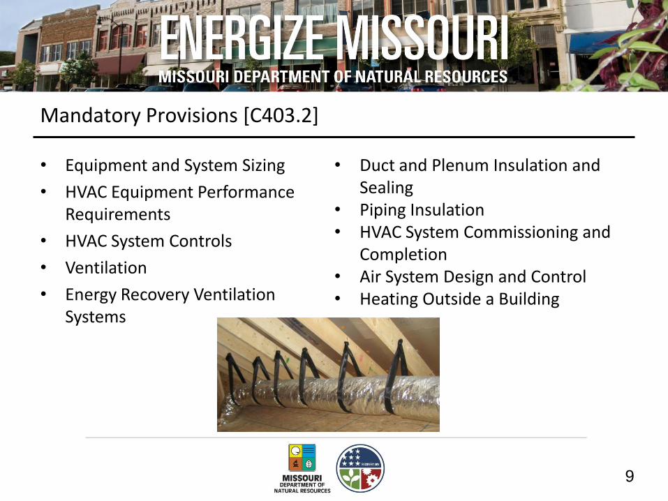
Mandatory Provisions [C403.2]
• Equipment and System Sizing
• HVAC Equipment Performance Requirements
• HVAC System Controls
• Ventilation
• Energy Recovery Ventilation Systems
• Duct and Plenum Insulation and Sealing
• Piping Insulation • HVAC System Commissioning and
Completion • Air System Design and Control • Heating Outside a Building

10
Equipment and System Sizing [C403.2.1 and C403.2.2]
Heating and cooling load calculations required
• ASHRAE/ACCA Standard 183
• Output capacity shall not exceed sizing
Exceptions
– Standby equipment with required controls
– Multiple units with combined capacities exceeding loads and required sequencing controls

11
HVAC Equipment Performance [C403.2.3]
Applies to all equipment used in heating and cooling of buildings
• Must comply with all listed efficiencies
(partial table)
EQUIPMENT TYPE SIZE CATEGORY HEATING SECTION
TYPE
SUBCATEGORY OR RATING
CONDITION
MINIMUM EFFICIENCY
TEST PROCEDURE
Air cooled (cooling mode)
< 65,000 Btu/h All Split system 13.0 SEER
AHRI 210/240
Single packaged 13.0 SEER
≤ 30,000 Btu/h All Split system 13.0 SEER
Single packaged 13.0 SEER Single-duct high-
velocity air cooled < 65,000 Btu/h All Split system 10.0 SEER

12
System Controls [C403.2.4.1-2]
• Programmable thermostats required for each zone or system if not zoned
• Prevent electrical-resistance supplemental heat operation in heat pumps
– Exception: defrost mode or when heat pump can not meet heating load
• Thermostats must have at least a 5°F dead band or manual change between heating and cooling

13
System Controls [C403.2.4.3]
Thermostatic setback capabilities from 55°F or up to 85°F
Automatic start controls for each HVAC system
• Capable of automatically adjusting daily start time
Motorized dampers are to automatically shut when the system is not in use
Automatic snow melt controls dependent on precipitation and temperature
Photo courtesy of Ken Baker, K energy
Exceptions
• Zones operated continually
• Zones with full HVAC load demand <6,800 Btu/h and has a readily accessible shut off switch

14
Demand Controlled Ventilation [C403.2.5.1]
DCV must be provided for each zone with spaces > 500 ft² and the average occupant load > 25 people/1000 ft² of floor area where the HVAC system has:
• An air-side economizer, or
• Automatic modulating control of the outdoor air damper, or
• A design outdoor airflow > 3,000 cfm
Demand control ventilation (DCV): a ventilation system capability that
provides for the automatic reduction of outdoor air intake below design
rates when the actual occupancy of spaces served by the system is
less than design occupancy.
15
Demand Controlled Ventilation [C403.2.5.1]
Exceptions
• Systems with energy recovery ventilation systems
• Multiple zone systems without direct digital control of single zones communicating with central control panel
• Systems with design outdoor airflow < 1,200 cfm
• Spaces where supply airflow rate minus any makeup or outgoing transfer air requirement < 1,200 cfm
• Ventilation provided for process loads only

16
Energy Recovery Ventilation Systems [C403.2.6]
• Applies to fan systems with large supply airflow rates
• Exhaust air recovery efficiency must be ≥ 50%
• When an air economizer is required
– include a bypass or controls that permit operation of economizer
Energy recovery ventilation (ERV) systems:
employ air-to-air heat exchangers to recover
energy from exhaust air for the purpose of
preheating, precooling, humidifying or
dehumidifying outdoor ventilation air prior to
supplying the air to a space, either directly or
as part of an HVAC system.

17
Energy Recovery Ventilation Systems [C403.2.6]
Exceptions:
• Where energy recovery ventilation systems prohibited by the IMC
• Certain types of lab fume hoods

18
Energy Recovery Ventilation Systems [C403.2.6]
Exceptions (cont.):
• Systems serving uncooled spaces and heated to < 60°F
• Where > 60% of outdoor heating energy is from site-recovered or site solar energy
• Cooling energy recovery in Climate Zones 3C, 4C, 5B, 5C, 6B, 7, and 8
• Systems requiring dehumidification that employ energy recovery in series with the cooling coil
• Where largest source of air exhausted at a single location at building exterior is < 75% of design outside air flow rate

19
Duct and Plenum Insulation & Sealing [C403.2.7]
Insulation required for supply and return ducts and plenums
• Unconditioned space: R-6
• Outside the building: R-8
Exceptions
• When located within equipment
• When design temperature difference between interior and exterior of the duct or plenum doesn’t exceed 15°F
20
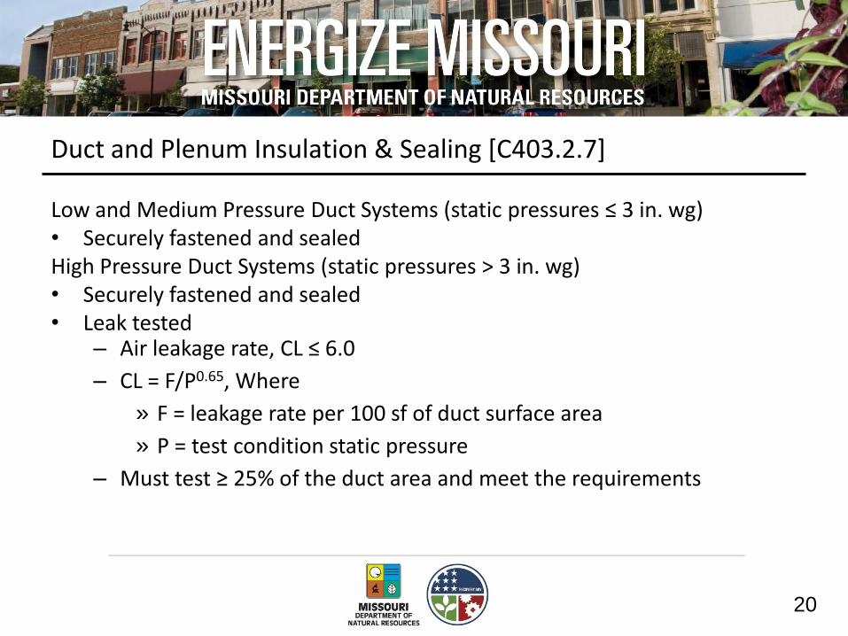
Duct and Plenum Insulation & Sealing [C403.2.7]
Low and Medium Pressure Duct Systems (static pressures ≤ 3 in. wg) • Securely fastened and sealed High Pressure Duct Systems (static pressures > 3 in. wg) • Securely fastened and sealed • Leak tested
– Air leakage rate, CL ≤ 6.0
– CL = F/P0.65, Where
» F = leakage rate per 100 sf of duct surface area
» P = test condition static pressure
– Must test ≥ 25% of the duct area and meet the requirements

21
Piping Insulation [C403.2.8]
Mechanical piping insulation [Table C403.2.8] for fluids ≤ 60°F or ≥ 105°F
• Between R-2 and R-16 dependent of temperature and pipe diameter
• Protect insulation from weather
– Sunlight, moisture, maintenance, wind, etc.
Exceptions
• Strainers, control valves, and balancing valves associated with piping ≤ 1” in diameter
• Direct buried piping for fluids ≤ 60 F
22
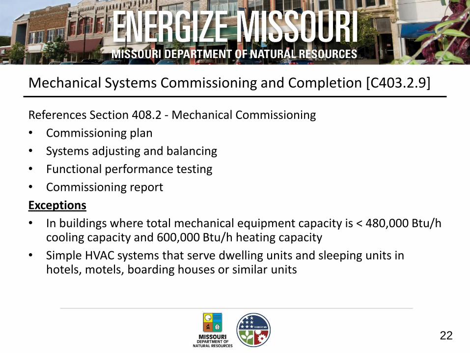
Mechanical Systems Commissioning and Completion [C403.2.9]
References Section 408.2 - Mechanical Commissioning
• Commissioning plan
• Systems adjusting and balancing
• Functional performance testing
• Commissioning report
Exceptions
• In buildings where total mechanical equipment capacity is < 480,000 Btu/h cooling capacity and 600,000 Btu/h heating capacity
• Simple HVAC systems that serve dwelling units and sleeping units in hotels, motels, boarding houses or similar units

23
Commissioning Plan [C408.2.1]
Developed by registered design professional or agency and include:
• Narrative description of activities to be accomplished during each phase of commissioning, including personnel who will do each activity
• Listing of specific equipment, appliances, or systems to be tested
• Functions to be tested
• Conditions under which test will be performed
– At a minimum, testing will affirm winter and summer design conditions and full outside air conditions
• Measurable criteria for performance

24
Systems Adjusting and Balancing [C408.2.2]
HVAC (air and water) systems measured and adjusted to be balanced
Air Exception
• Fans with motors ≤ 1hp
Hydronic Exceptions
• Pumps with pump motors ≤ 5hp
• Where throttling results in ≤ 5% of nameplate hp draw above that required if the impeller were trimmed
25
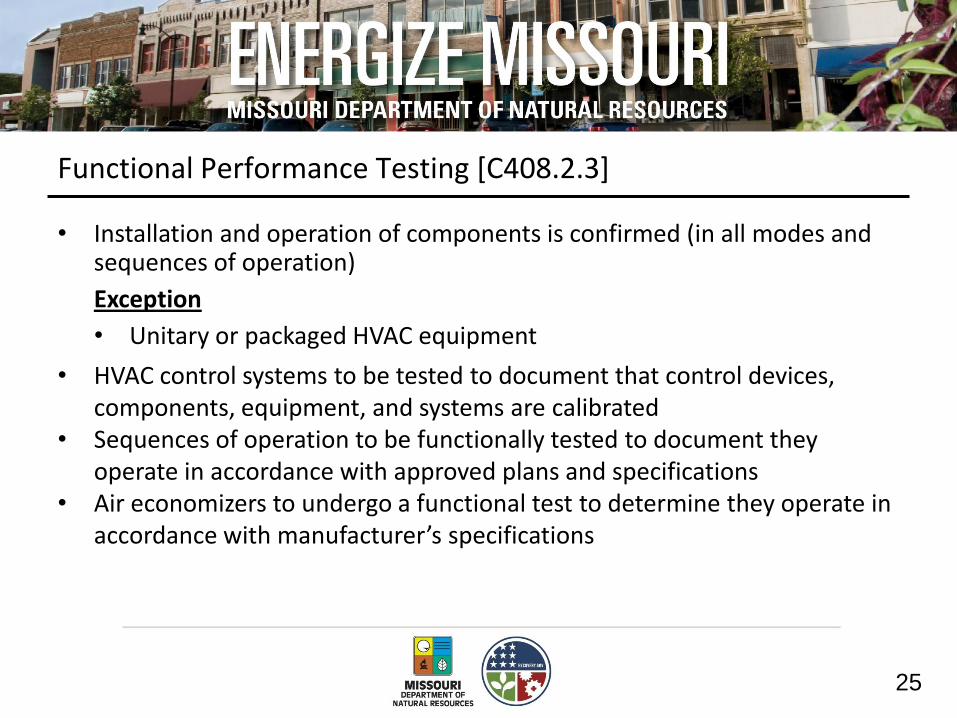
Functional Performance Testing [C408.2.3]
• Installation and operation of components is confirmed (in all modes and sequences of operation)
Exception
• Unitary or packaged HVAC equipment
• HVAC control systems to be tested to document that control devices, components, equipment, and systems are calibrated
• Sequences of operation to be functionally tested to document they operate in accordance with approved plans and specifications
• Air economizers to undergo a functional test to determine they operate in accordance with manufacturer’s specifications
26
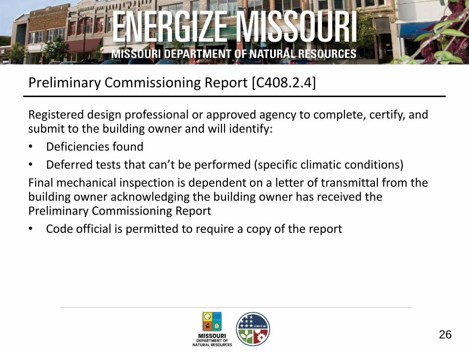
Preliminary Commissioning Report [C408.2.4]
Registered design professional or approved agency to complete, certify, and submit to the building owner and will identify:
• Deficiencies found
• Deferred tests that can’t be performed (specific climatic conditions)
Final mechanical inspection is dependent on a letter of transmittal from the building owner acknowledging the building owner has received the Preliminary Commissioning Report
• Code official is permitted to require a copy of the report

27
Documentation Requirements [C408.2.5]
Provided to building owner within 90 days of certificate of occupancy
• Drawings
– Include location and performance data on each piece of equipment
• Operating and Maintenance Manuals
– Installed equipment and controls with manuals
– Name and address of at least one service agency
• System balancing report
– Description of the activities and measurements completed
• Final commissioning report
– Results (not just deficiencies) with procedures and performance
– List any tests not performed for climatic reasons

28
Air System Design and Control [C403.2.10]
• Maximum fan power requirements
• Applies to HVAC systems with total fan system power > 5 hp
• Each HVAC system at design conditions can not exceed both:
– The allowable fan system motor nameplate hp
– The fan system bhp in Table C403.2.10.1(1)
» bhp can be increased by pressure drop adjustments (A factor)
» bhp = brake horsepower
29
Allowable Fan Motor Horsepower [C403.2.10.1]
Exceptions
• Hospital, vivarium, and laboratory systems using flow control devices on exhaust and/or return for health and safety or environmental control permitted to use variable fan power limitation
• Individual exhaust fans ≤ 1 hp

30
Motor Nameplate Horsepower [C403.2.10.2]
• Selected fan motor to be no larger than first available motor size greater than bhp
• Fan bhp on design documents
Exceptions
• Fans < 6 bhp, where first available motor larger than bhp has nameplate rating within 50% of bhp, next larger nameplate motor size may be selected
• Fans ≥ 6 bhp, where first available motor larger than bhp has nameplate rating within 30% of bhp, next larger nameplate motor size may be selected

31
Heating Outside a Building [C403.2.11]
• Systems are to be radiant systems
• Controlled by an occupancy sensing device or timer switch
• Other control requirements for snow melt systems in C403.2.4.5

32
Simple Versus Complex Systems
Simple systems
• Unitary or packaged HVAC equipment serving one zone and controlled by a single thermostat
• Two-pipe heating systems serving multiple zones (if no cooling system)
Complex systems
• All equipment not covered under Section C403.3 Simple Systems

33
Simple HVAC Systems & Equipment [C403.3]
Unitary or packaged, single zone controlled by a single thermostat in the zone served.
Simple Systems
• Unitary packaged heating and cooling systems
• Split system heating and cooling systems
• Packaged terminal A/C and HPs
• Fuel-fired furnace
• Electrical resistance heating
• Two-pipe heating systems w/o cooling

34
Economizers [C403.3.1]
• Capable of modulating dampers to provide 100% of design supply air quantity as outdoor air for cooling
Each cooling system with a fan shall include either an air or water economizer

35
Economizers [C403.3.1]
Exceptions (economizers not required)
• System cooling capacity is < 33 kBtu/h
• Where > 25% of air designed to be supplied by the system is to spaces that are designed to be humidified > 35°F dew-point temperature to satisfy process needs
• Systems that serve residential spaces and system capacity is < 165 kBtu/h
• Systems expected to operate < 20 hours/week
• Where use of outdoor air for cooling will affect supermarket open refrigerated casework systems

36
Air Economizers Control Signal [C403.3.1.1.2]
Economizer dampers to be capable of being sequenced with mechanical cooling equipment and not be controlled by only mixed air temperature Exception
• Can use mixed air temperature limit control for systems controlled from space temperature
– Example: single-zone systems

37
Air Economizers High-Limit Shutoff [C403.3.1.1.3]
• Air economizers to be capable of automatically reducing outdoor air intake to design minimum outdoor air quantity when outdoor air intake will no longer reduce cooling energy usage

38
Air Economizers Relief of Excess Outdoor Air [C403.3.1.1.4]
• Systems to be capable of relieving excess outdoor air during air economizer operation to prevent over-pressurizing the building
• Relief air outlet to be located to avoid recirculation into the building

39
Hydronic System Controls [C403.3.2]
• Hydronic systems < 300,000 Btu/h - no additional requirements
• Hydronic systems ≥ 300,000 Btu/h - controls complying with the complex hydronic system requirements

40
Complex HVAC Systems & Equipment [C403.4]
This section applies to all HVAC equipment and systems not included in Section C403.3
Complex Systems
• Packaged VAV reheat
• Built-up VAV reheat
• Built-up single-fan, dual-duct VAV
• Built-up or packaged dual-fan, dual-duct VAV
• Four-pipe fan coil system with central plant
• Water Source heat pump with central plant
• Any other multiple-zone system
• Hydronic space heating and cooling system

41
Economizer Design Capacity [C403.4.1.1]
Water economizer systems
• Capable of providing 100% of the cooling system load at 50°F dry bulb/45°F wet bulb and below
Exception
• Water economizer systems where dehumidification requirements can’t be met at 50°F dry bulb/45°F wet bulb
– Satisfy 100% of expected cooling load at 45°F dry bulb/40°F wet bulb

42
Economizer Maximum Pressure Drop [C403.4.1.2]
Precooling coils and water-to-water heat exchangers in water economizer systems to have either a: • Waterside pressure drop of < 15 ft of water OR • Secondary loop created so coil or heat exchanger drop isn’t seen by
circulating pumps when system is in normal cooling mode
43
Economizer Control [C403.4.1.3]
Economizers shall be integrated with mechanical cooling system and be capable of providing partial cooling even when additional mechanical cooling is required to meet remainder of cooling load
Exceptions
• Direct expansion systems with controls that reduce quantity of outdoor air required to prevent coil frosting at lowest step of compressor unloading, provided this lowest step is ≤ 25% of total system capacity
• Individual direct expansion units with rated cooling capacity < 54,000 Btu/h and use nonintegrated economizer controls that preclude simultaneous operation of the economizer and mechanical cooling

44
Economizer Heating System Impact [C403.4.1.4]
• Economizer operation to not increase building heating energy use during normal operation
Exception
• Economizers on VAV systems that cause zone level heating to increase due to a reduction in supply air temperature

45
Variable Air Volume Fan Control [C403.4.2]
Individual VAV fans with motors ≥ 7.5hp must be:
• Driven by a mechanical or electrical variable speed drive
OR
• Driven by a vane-axial fan with variable-pitch blades
OR
• Have controls or devices to result in fan motor demand ≤ 30% of their design wattage at 50% of design airflow
0%
20%
40%
60%
80%
100%
120%
0% 20% 40% 60% 80% 100%
Airflow Part Load Ratio
Fa
n P
ow
er
PL
R

46
Variable Air Volume Fan Control [C403.4.2]
Sensors used to control VAV fans
• Placed so that the controller setpoint is ≤ 1/3 the total design fan static pressure
Sensors installed downstream of major duct splits
• At least one sensor to be located on each major branch so that static pressure can be maintained in each branch
Systems with direct digital control of individual zone boxes reporting to the central control panel • Static pressure reset point to be reset based on the zone requiring the
most pressure (i.e., the set point is reset lower until one zone damper is nearly wide open)

47
Hydronic System Controls [C403.4.3]
• Limit reheat/recool of fluids
– Common return (hot and chilled water) is prohibited
– Two-pipe changeover systems must have a dead band between changeover ≥ 15 F outside temperature
• Multiple boiler heating plants must include automatic controls capable of sequencing operation of the boilers
• Single boilers > 500,000 Btu/h must have either a multi-staged or modulating burner

48
Hydronic Systems [C403.4.3]
3-Pipe System – not allowed • Can’t use a common return 2-Pipe Changeover System • Dead band between changeover ≥ 15ºF outside temperature

49
Hydronic Water Loop Heat Pump Systems [C403.4.3.3]
Temperature dead band of at least 20°F
Exception
• Where system loop temp optimization controller is installed and can determine the most efficient operating temp based on realtime conditions of demand and capacity

50
Hydronic Water Loop Heat Pump Systems [C403.4.3.3]
Heat rejection equipment in Climate Zones 4
• Closed-circuit cooling tower used directly in heat pump loop
– Install either automatic valve to bypass all but a minimal flow of water around tower OR lower leakage positive closure dampers to be provided
• Open-circuit tower used directly in heat pump loop
– Install automatic valve to bypass all heat pump water flow around tower
• Open- or closed-circuit used in conjunction with separate heat exchanger to isolate cooling tower from heat pump loop
– Heat loss controlled by shutting down the circulation pump on cooling tower loop
51
Hydronic Water Loop Heat Pump Systems [C403.4.3.3]
Heat rejection equipment in Climate Zones 5
• Open- or closed-circuit cooling tower used
– Must have a separate heat exchanger to isolate cooling tower from heat pump loop
– Heat loss controlled by shutting down circulation pump on cooling tower loop and providing an automatic valve to stop flow of fluid

52
Hydronic Water Loop Heat Pump Systems [C403.4.3.3]
Two position valve (C403.4.3.3.3)
• Required on each hydronic heat pump with total pump system power > 10 hp
53
Hydronic System Part Load Control [C403.4.3.4]
System ≥ 300,000 Btu/h must include
• Temperature reset or variable flow
Automatic resets for supply water temperature by at least 25% of design supply-to-return temperature differences
or
Reduce system pump flow by 50% of design flow using:
• Multiple Staged Pumps
• Adjustable Speed Drives
• Control Valves that modulate as a function of load

54
Pump Isolation [C403.4.3.5]
Capability to reduce flow through the equipment automatically when equipment is shut down
• Chiller(s)
• Boiler(s)

55
Heat Rejection Equipment Fan Speed Control [C403.4.4]
Each fan powered by a motor ≥ 7.5 hp must have the capability to operate that fan at two-thirds of full speed or less (variable or multi-speed)
• Have controls to automatically change the fan speed Exception
• Factory-installed heat rejection devices within condensers and chillers tested and rated in accordance with the minimum efficiency tables
56
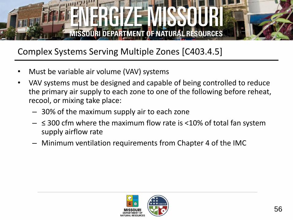
Complex Systems Serving Multiple Zones [C403.4.5]
• Must be variable air volume (VAV) systems
• VAV systems must be designed and capable of being controlled to reduce the primary air supply to each zone to one of the following before reheat, recool, or mixing take place:
– 30% of the maximum supply air to each zone
– ≤ 300 cfm where the maximum flow rate is <10% of total fan system supply airflow rate
– Minimum ventilation requirements from Chapter 4 of the IMC

57
Complex Systems Serving Multiple Zones [C403.4.5]
Exceptions
• Zones with special pressurization or cross-contamination requirements
• Where 75% of reheat energy comes from site-recovered or site-solar energy source
• Zones with special humidity requirements
• Zones with ≤ 300 cfm peak supply and flow rate is < 10% of total fan system supply airflow rate
• Zones where reheated, recooled or mixed air volume < minimum ventilation requirements (Chapter 4 of IMC)
• Systems with controls capable of preventing reheating, recooling, mixing or simultaneous supply of air previously heated or cooled

58
Single Duct VAV Systems, Terminal Devices [C403.4.5.1]
Single duct VAV systems to use terminal devices capable of reducing the supply of primary supply air before reheating or recooling takes place

59
Dual Duct and Mixing VAV Systems, Terminal Devices [C403.4.5.2]
Systems with one warm and one cool air duct must use terminal devices capable of reducing flow from one duct to a minimum before mixing of air from the other duct takes place

60
Single Fan Dual Duct and Mixing VAV Systems [C403.4.5.3]
Individual dual duct or mixing heating and cooling systems with a single fan and with total capacities > 90,000 Btu/h (7.5 tons) should not have air economizers

61
Supply-Air Temperature Reset Controls [C403.4.5.4]
Multiple zone HVAC systems to have controls to automatically reset supply-air temperature in response to building loads or outdoor air temperature
Controls to be capable of resetting supply air temperature at least 25% of difference between design supply-air temperature and design room air temperature
Exceptions
• Systems that prevent reheating, recooling or mixing of heated and cooled supply air
• 75% of energy for reheating is from site-recovered or site solar energy sources
• Zones with peak supply air quantities of ≤ 300 cfm

62
Heat Recovery for Service Hot Water Heating [C403.4.6]
CW In
HW In
Storage Tank
Condenser
Evaporator
Heat Recovery
Heat Pump
Cooling Tower
Water Loop
To Chiller Condenser or
Water-Loop Heat Pump
System
CW In
HW In
Storage Tank
Condenser
Evaporator
Heat Recovery
Heat Pump
Cooling Tower
Water Loop
To Chiller Condenser or
Water-Loop Heat Pump
System
Condenser heat recovery required for heating/reheating of SWH provided:
• Facility operates 24 hours/day
• Heat capacity of the water-cooled systems > 6,000,000 Btu/hr
• Design SWH load >1,000,000 Btu/hr
Capacity to provide the smaller of
• 60% of peak heat rejection load at design conditions OR
• Preheating to raise peak SHW to 85ºF
Exceptions
• Recovered heat is used for space heating or when SHW is provided by renewables or site recovered energy sources

63
Hot Gas Bypass [C403.4.7]
Cooling systems can not use hot gas bypass unless system designed with
• Multiple steps of unloading OR
• Continuous capacity modulation
Capacity limited per Table C403.4.7
Exception
• Unitary packaged systems with cooling capacities < 90,000 Btu/h

64
2012 IECC Compliance
Prescriptive IECC Requirements
Envelope Requirements
Mechanical/SWH Requirements
Power & Lighting Requirements
Section 402 Sections 403 Section 405 Sections 404
Additional Efficiency
Requirements
Section 406

65
Service Water Heating [C404]
Requirements:
• Minimum Efficiency Performance
• Temperature Controls
• Heat Traps
• Pipe Insulation
• Controls
• Pools and Spas
66
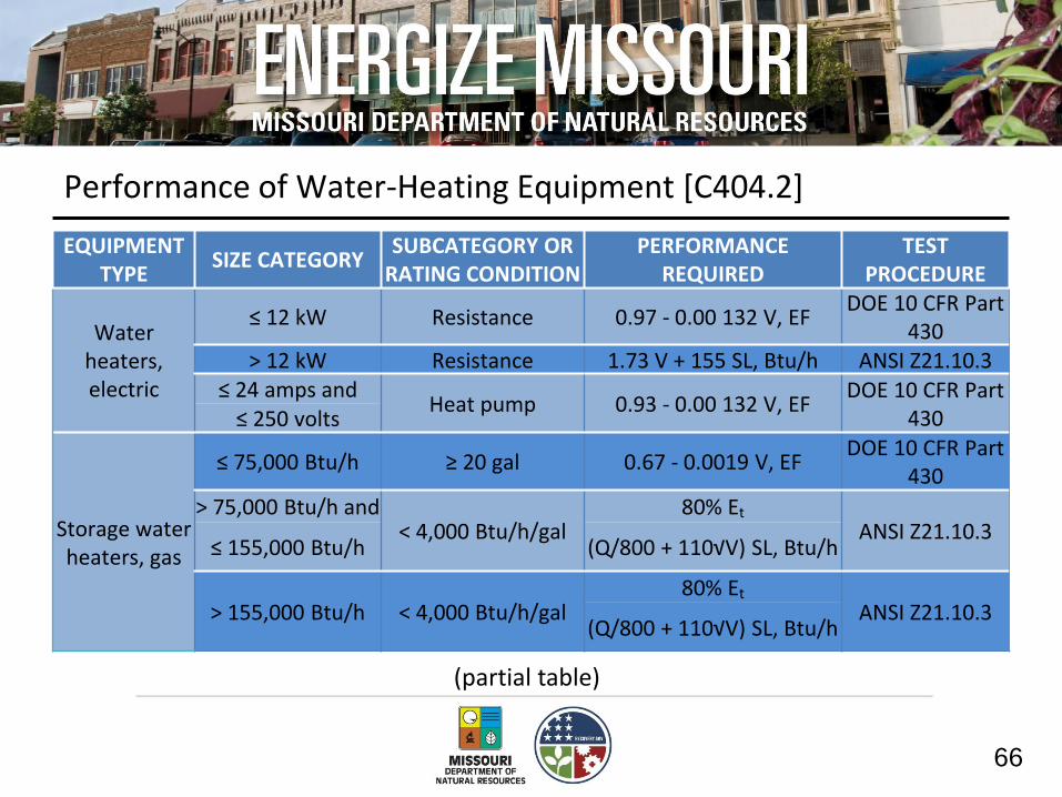
Performance of Water-Heating Equipment [C404.2]
EQUIPMENT TYPE
SIZE CATEGORY SUBCATEGORY OR
RATING CONDITION PERFORMANCE
REQUIRED TEST
PROCEDURE
Water heaters, electric
≤ 12 kW Resistance 0.97 - 0.00 132 V, EF DOE 10 CFR Part
430 > 12 kW Resistance 1.73 V + 155 SL, Btu/h ANSI Z21.10.3
≤ 24 amps and Heat pump 0.93 - 0.00 132 V, EF
DOE 10 CFR Part 430 ≤ 250 volts
Storage water heaters, gas
≤ 75,000 Btu/h ≥ 20 gal 0.67 - 0.0019 V, EF DOE 10 CFR Part
430
> 75,000 Btu/h and < 4,000 Btu/h/gal
80% Et ANSI Z21.10.3
≤ 155,000 Btu/h (Q/800 + 110√V) SL, Btu/h
> 155,000 Btu/h < 4,000 Btu/h/gal 80% Et
ANSI Z21.10.3 (Q/800 + 110√V) SL, Btu/h
(partial table)

67
Temperature Controls [C404.3]
Setpoints:
• Dwelling units - 110°F
• Public facility rest rooms - 110°F
• All other - 90°F

68
Heat Traps [C404.4]
Heat traps required on the supply and discharge piping associated with the equipment
Exceptions
• Integral heat traps with equipment
• Circulating systems

69
Pipe Insulation [C404.5]
Noncirculating system insulation requirements
• First eight feet of outlet piping on systems with no integral heat traps
• ≥ ½ inch of insulation required
Circulating systems and heat-traced systems
• ≥ 1 inch of insulation

70
Hot Water System Controls [C404.6]
Ability to turn off circulating hot water pumps and heat trace when there is limited demand
• Automatically or manually
• Readily accessible

71
Pools and Inground Permanently Installed Spas [C404.7]
• Accessible on-off switch
• No continuously burning pilot lights
• Automatic time controls for heaters and pumps except for public health reasons or if required for solar- and waste-heat systems
• Vapor-retardant covers
– Exception: heating from renewable energy

72
Topic 1 Summary
Mechanical requirements
• Mandatory requirements
• Commissioning requirements
• Simple vs. complex systems
Service water heating requirements
73
Topic 2
Lighting requirements of the 2012 IECC

74
2012 IECC Compliance
Prescriptive IECC Requirements
Envelope Requirements
Mechanical/SWH Requirements
Power & Lighting Requirements
Section 402 Sections 403 Section 405 Sections 404
Additional Efficiency
Requirements
Section 406

75
Electrical Power and Lighting Systems [C405]
Requirements:
• Controls
• Tandem wiring
• Exit signs
• Interior lighting power allowances (watts/ft2)
• Exterior lighting power allowances (watts/ft2)
• Separate electric metering
76
Electrical Power and Lighting Systems [C405.1]
Application:
• New building, addition, or tenant build-out
• Replacement of more than 50% of existing luminaires
• Change in occupancy that increases lighting energy or requires less energy
Exceptions
• Lighting within dwelling units
– ≥ 75% of permanently installed fixtures (except low-voltage) are installed with high-efficacy lamps
– Must still meet exterior lighting [C405.6] and separate metering [C405.7] requirements

77
Manual Lighting Controls [C405.2.1]
• Manual control, located in space served, required for each space surrounded by floor-to-ceiling partitions
OR
• Control in a remote location with an indicator that identifies the area served and their status
Exceptions
• Security or emergency
• Egress lighting

78
Light Reduction Controls [C405.2.1.2]
• Controlled by occupancy sensor
• Sleeping units
• Spaces with <0.6 w/ft2
• Areas with only one luminaire with rated power < 100 W
• Corridors, equipment rooms, storerooms, restrooms, public lobbies, electrical or mechanical rooms
• Daylight spaces complying with Section C405.2.2.3.2
Must allow the occupant to reduce connected lighting
• By at least 50% in uniform a pattern
Exemptions

79
Light Reduction Control Options [C405.2.1.2]
S S
Dimmer Switch
D
Alternating Luminaires
Dimming
S S
Alternating Lamps

80
Additional Lighting Controls [C405.2.2]
Each area required to have a manual control to also have controls meeting:
• Automatic time switch control devices
• Occupancy sensors
• Daylight zone control
Exceptions
• Sleeping units
• Lighting for patient care
• When an automatic shutoff would endanger occupant safety or security
• Lighting intended for continuous operation

81
Automatic Time Switch Control Devices [C405.2.2.1]
Automatic time switch installed with override switching device control:
• Readily accessible from within view of the area controlled
• ≤ 2 hour override
• Controls an area ≤ 5,000 ft2
Exemptions
• Egress lighting
• Controlled by occupancy sensor
• Time limit and maximum area are both increased for malls, arcades, auditoriums, single-tenant retail space, industrial facilities and arenas

82
Occupancy Sensors [C405.2.2.2]
• Classrooms
• Conference/meeting rooms
• Employee lunch and break rooms
• Private offices
• Restrooms
• Storage rooms and janitorial closets
• Other spaces < 300 ft2 enclosed by floor-to-ceiling height partitions
Occupancy sensors are required in:
Features:
• Within 30 minutes of occupants leaving space
• Manual switch or controlled to automatically turn lighting on to not more than 50% power (100% allowed in public corridors, stairways, restrooms, primary building entrance areas and lobbies, areas with safety or security concern)
83
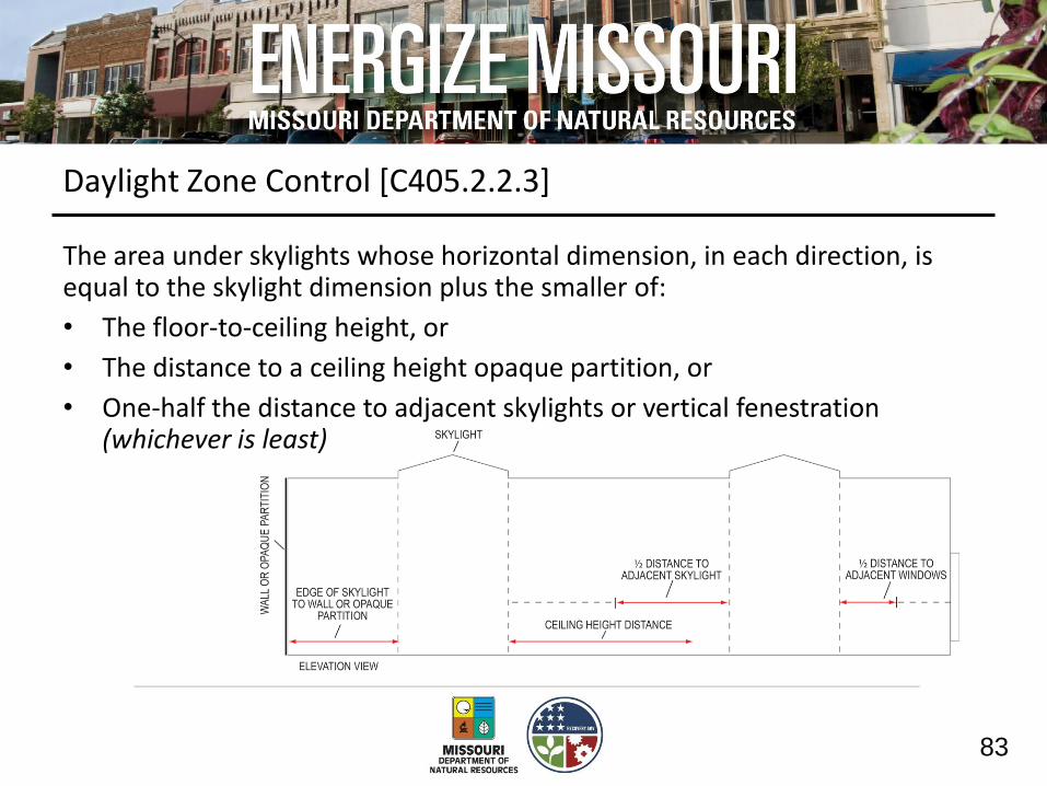
Daylight Zone Control [C405.2.2.3]
The area under skylights whose horizontal dimension, in each direction, is equal to the skylight dimension plus the smaller of:
• The floor-to-ceiling height, or
• The distance to a ceiling height opaque partition, or
• One-half the distance to adjacent skylights or vertical fenestration (whichever is least)

84
Daylight Zone Control [C405.2.2.3]
or the window width plus one-half the distance to adjacent skylight or vertical fenestration, whichever is least.
The daylight zone depth for windows is assumed to be 15 feet into the space or to the nearest opaque partition, whichever is less
The daylight zone width is assumed to be the width of the window plus 2 feet on each side, or the window width plus distance to opaque partitions,

85
Daylight Zone Control [C405.2.2.3]
Daylight Zones
• Individual control of the lights independent of general area lighting
• Controlled per automatic or manual daylighting controls
• Each daylight control zone to be ≤ 2500 ft2
Single controlling device allowed
• If adjacent zones don’t include areas facing > two adjacent orientations
• If the skylight daylight zones are < 15 ft from the perimeter
Exception
• Daylight zones enclosed by walls or ceiling height partitions and containing two or fewer light fixtures are not required to have a separate switch for general area lighting
86
Daylight Zone Control [C405.2.2.3]
Manual Daylighting Controls [C405.2.2.3.1]
Manual controls in daylight zones
Exemption:
Unless automatic controls are installed per C405.2.2.3.2 Automatic Daylighting Controls

87
Daylight Zone Control [C405.2.2.3]
Automatic Daylighting Controls [C405.2.2.3.2]
• Lighting control device to be readily accessible (calibration and set-points)
• Device capable of automatically reducing the lighting power either by:
– Continuous dimming capable of reducing general lighting power in daylit zone continuously to < 35% of rated power at maximum light output
OR
– Stepped dimming using multi-level switching. System required to provide at least two levels per zone (between 50-70% and < 35)

88
Specific Application Controls [C405.2.3]
• Dedicated and independent control must be installed for:
– Display and accent lighting
– Display case lighting
– Nonvisual applications (i.e., plant growth and food warming)
– Lighting equipment for sale or demonstration in lighting education
• Hotel and motel sleeping units and guest suites
– Master control device at main room entry for all permanent luminaires and switched receptacles
• Supplemental task lighting, (i.e., under-shelf or under-cabinet lighting)
– Have control device integral to luminaires or controlled by readily accessibly, wall-mounted control device

89
Exterior Lighting Control Requirements [C405.2.4]
• For dusk-to-dawn lighting: astronomical time switch or photosensor
• For all other: astronomical time switch or photosensor + time switch
• All time switches must have at least 10 hour battery backup
90
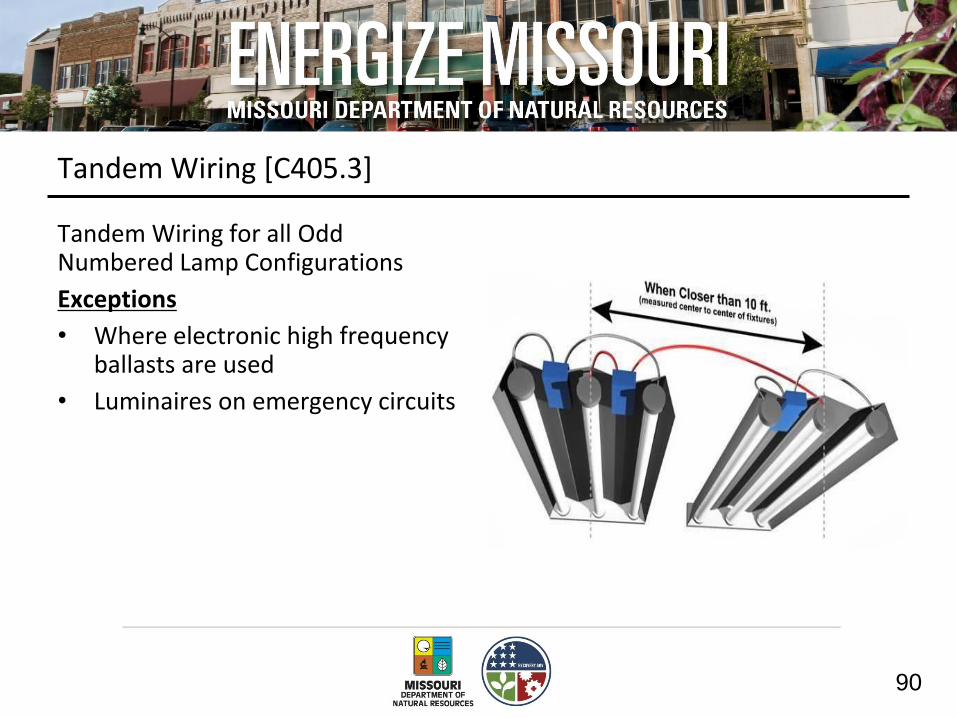
Tandem Wiring [C405.3]
Tandem Wiring for all Odd Numbered Lamp Configurations
Exceptions
• Where electronic high frequency ballasts are used
• Luminaires on emergency circuits

91
Exit Signs [C405.4]
Exit Signs
• Internally illuminated exit signs shall not exceed 5 watts per side

92
Interior Lighting Power Allowance [C405.5.2]
Two methods to determine allowance:
• Building Area Method
– Floor area for the building multiplied by allowance for that building
• Space-by-Space Method
– Floor area of each space multiplied by allowance for the space
– Then sum the allowances for all the spaces
– Tradeoffs among spaces are allowed

93
Building Area Method [Table C405.5.2(1)]
Building Area Type LPD (w/ft2)
Automotive facility 0.9
Convention center 1.2
Courthouse 1.2
Dining: bar lounge/leisure 1.3
Dining: cafeteria/fast food 1.4
Dining: family 1.6
Dormitory 1.0
Exercise center 1.0
(partial table)

94
Space-By-Space Method [Table C405.5.2(2)]
Common Space-by-Space Types LPD (w/ft2)
Atrium – First 40 feet in height 0.03 per ft. ht.
Atrium – Above 40 feet in height 0.02 per ft. ht.
Audience/seating area – permanent
For auditorium 0.9
For performing arts theater 2.6
For motion picture theater 1.2
Classroom/lecture/training 1.30
Conference/meeting/multipurpose 1.2
Corridor/transition 0.7
(partial table)

95
Additional Retail Lighting Power Allowance [Table C405.5.2(2)]
Additional Interior Lighting Power Allowance = 500 watts + (Retail Area 1 x 0.6 W/ft2) + (Retail Area 2 x 0.6 W/ft2) + (Retail Area 3 x 1.4 W/ft2) + (Retail Area 4 x 2.5 W/ft2)
Where: 1. Other 2. Vehicles, sporting goods and
small electronics 3. Furniture, clothing, cosmetics
and artwork. 4. Jewelry, crystal, and china
96
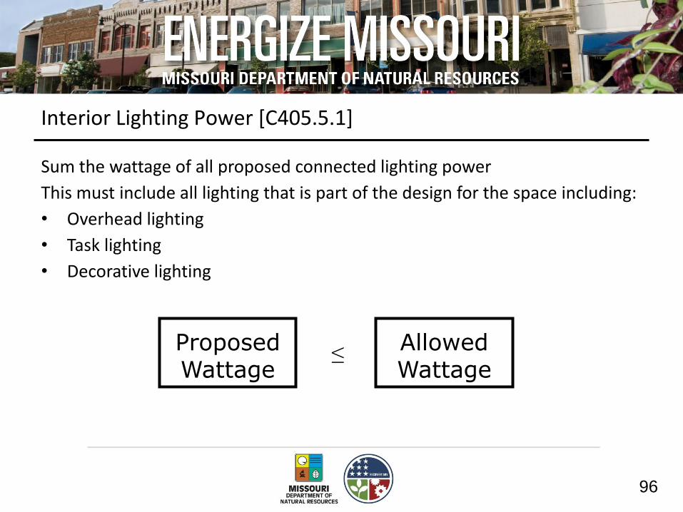
Interior Lighting Power [C405.5.1]
Sum the wattage of all proposed connected lighting power
This must include all lighting that is part of the design for the space including:
• Overhead lighting
• Task lighting
• Decorative lighting
Allowed Wattage
Proposed Wattage
≤

97
Interior Lighting Power [C405.5.1]
Lighting wattage rules:
• Screw lamp holders - maximum labeled wattage of the luminaire
• Low voltage lighting - transformer wattage
• Line voltage track:
1. specified wattage with minimum of 30 W/linear ft OR
2. wattage limit of system’s circuit breaker OR
3. wattage limit of other permanent current limiting devices
• Other: manufacturer’s rated wattage of lamp and associated ballast

98
Interior Lighting Power [C405.5.1]
Connected power for following not included in calculations:
• Professional sports arena playing field
• Sleeping unit lighting
• Emergency lighting automatically off during normal building operation
• Casino gaming areas
• Theatrical lighting
• Lighting for plant growth
• Lighting in restaurants for food warming
(partial list)

99
Exterior Lighting Controls [C405.6.1]
Exterior grounds lighting over 100 W provides >60 lm/W unless on motion sensor or fixture is exempt from code

100
Exterior Lighting Power [C405.6.2]
Connected Exterior Lighting Power must not exceed Exterior Lighting Power Allowance
• Calculate exterior lighting power allowance
– Lighting power densities by exterior function and by applicable lighting zone
• Calculate proposed connected lighting power
– Wattage calculation “rules”
– Exempted lighting
Allowed Wattage
Proposed Wattage
≤

101
Exterior Lighting Power Limits [C405.6.2]
Tradable surfaces
• Common exterior lighted needs that can be traded for other needs
– Parking lot lighting can be “traded” and used for canopy lighting
Nontradable surfaces
• Less common exterior lighted needs that cannot be traded for other needs
• These applications have more specific security or task illuminance needs
– Automated teller machines
102
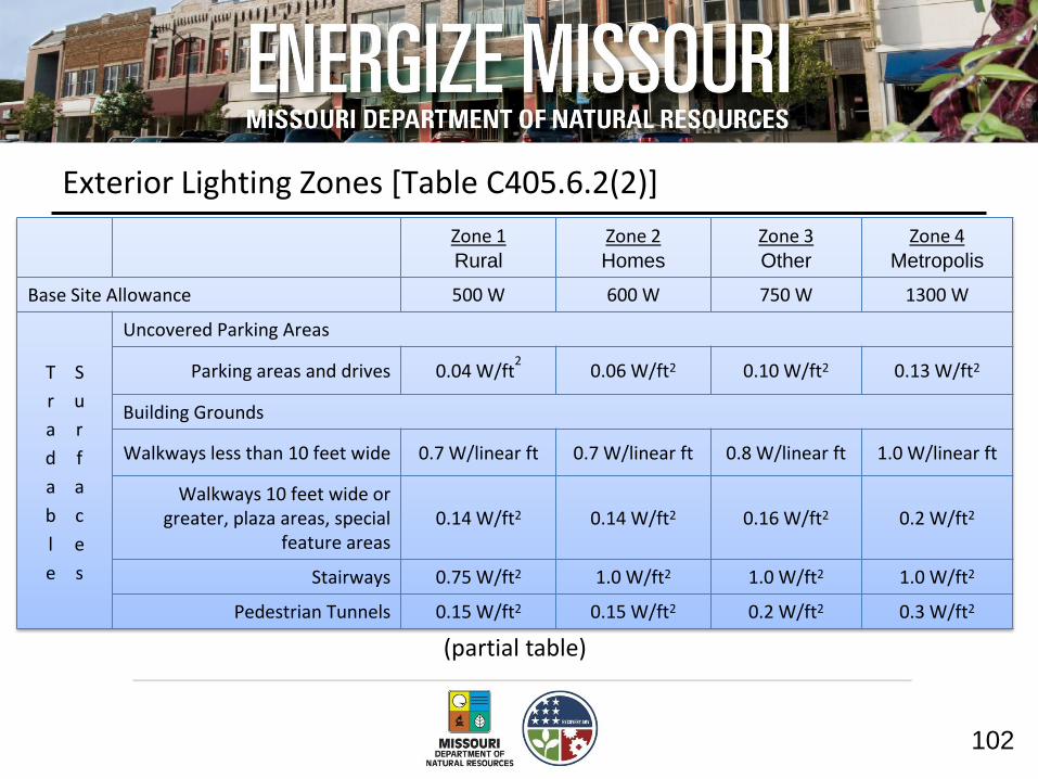
Exterior Lighting Zones [Table C405.6.2(2)]
(partial table)
Zone 1 Rural
Zone 2 Homes
Zone 3 Other
Zone 4 Metropolis
Base Site Allowance 500 W 600 W 750 W 1300 W
T
r
a
d
a
b
l
e
S
u
r
f
a
c
e
s
Uncovered Parking Areas
Parking areas and drives 0.04 W/ft2 0.06 W/ft2 0.10 W/ft2 0.13 W/ft2
Building Grounds
Walkways less than 10 feet wide 0.7 W/linear ft 0.7 W/linear ft 0.8 W/linear ft 1.0 W/linear ft
Walkways 10 feet wide or greater, plaza areas, special
feature areas 0.14 W/ft2 0.14 W/ft2 0.16 W/ft2 0.2 W/ft2
Stairways 0.75 W/ft2 1.0 W/ft2 1.0 W/ft2 1.0 W/ft2
Pedestrian Tunnels 0.15 W/ft2 0.15 W/ft2 0.2 W/ft2 0.3 W/ft2

103
Exemptions from Exterior Calculation [C405.6.2]
Connected power for following not included in calculations:
• Specialized signal, directional, and marker lighting associated with transportation
• Advertising signage or directional signage
• Theatrical lighting
• Lighting for athletic playing areas
• Lighting used to highlight features of public monuments and registered historic landmark structures or buildings
(partial list)
104
Electrical Energy Consumption [C405.7]
Separate metering required for each dwelling unit

105
Lighting System Functional Testing [C408.3]
• Testing to ensure that control hardware and software are calibrated, adjusted, programmed and in proper working order
• Construction documents to state who will conduct the testing
• Where required by the code official
– An approved independent party shall be responsible for the testing and documentation certifying the installed controls meet the provisions
106
Lighting System Functional Testing [C408.3]
Where the following are installed:
Occupant sensors Programmable schedule controls
Time switches Photosensors Daylighting controls
It is required that the following be confirmed:
• Placement, sensitivity and time-out adjustments for occupant sensors yield acceptable performance
• Time switches and programmable schedule controls are programmed to turn the lights off
• Placement and sensitivity adjustments for photosensor controls reduce electric light based on the amount of usable daylight in the space as specified

107
Topic 2 Summary
Lighting requirements
• Interior Lighting
• Exterior Lighting
• Mandatory requirements
– Commissioning requirements

108
Topic 3
Additional efficiency package requirements of the 2012 IECC
109
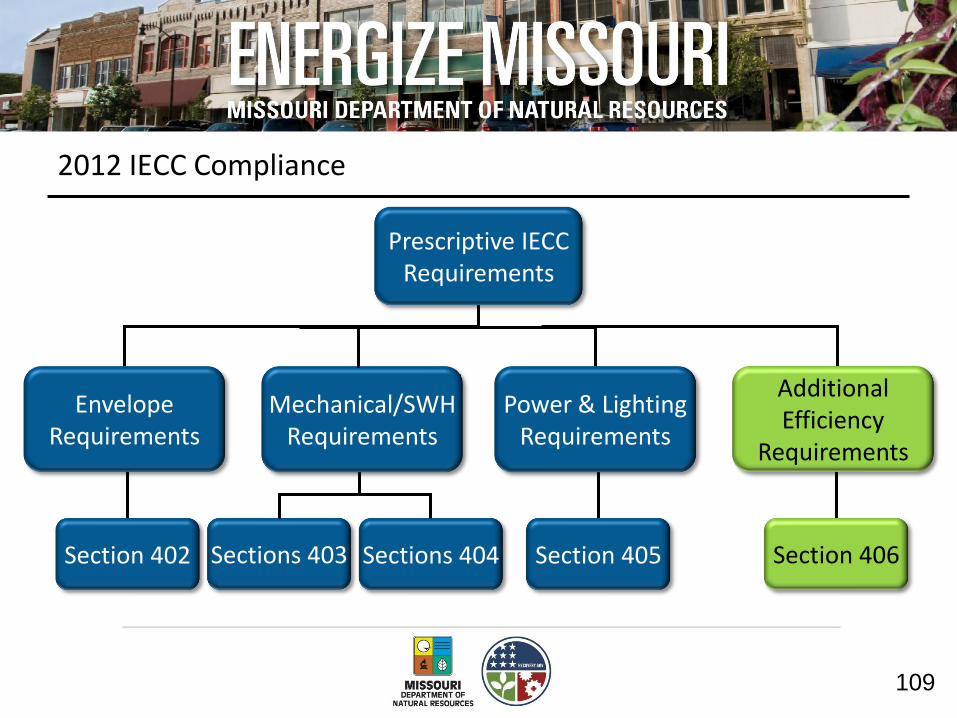
2012 IECC Compliance
Prescriptive IECC Requirements
Envelope Requirements
Mechanical/SWH Requirements
Power & Lighting Requirements
Section 402 Sections 403 Section 405 Sections 404
Additional Efficiency
Requirements
Section 406

110
Additional Efficiency Package Options [C406]
One additional efficiency feature must be selected to comply with the IECC
High Efficiency HVAC
More Efficient Lighting System
On-site Renewables
111
Efficient HVAC Performance [C406.2]
• Per equipment efficiency tables - C406.2(1) thru C406.2(7)

112
Efficient Lighting System [C406.3]
• Whole building lighting power density (LPD)
• Determine total lighting allowance of the building using reduced whole building interior lighting power densities
Building Area Type Standard LPD (w/ft2)
Efficient LPD (w/ft2)
Automotive facility 0.9 0.82
Convention center 1.2 1.08
Courthouse 1.2 1.05
Dining: bar lounge/leisure 1.3 0.99
(partial table)

113
On-Site Renewable Energy [C406.4]
• Minimum amount of renewables:
– Provide ≥ 1.75 Btu or ≥ 0.50 watts per ft2 of conditioned floor area OR
– Provide ≥ 3% of energy used for mechanical and SWH equipment and lighting

114
Topic 3 Summary
Energy Efficiency Package
• HVAC
• Lighting
• Renewables
Relates to the total building performance compliance path requirement of 85% of the energy of the reference house

115
Next Steps
Adoption of the IECC
• How are current practices different?
• Obstacles to implementing the code?
• Solutions?

116
Thank You – comment card Acknowledgment: “This material is based upon work supported by the U.S. Department of Energy through the Missouri Department of Natural Resources under Award Number DE-EE0000131.” Disclaimer: “This report was prepared as an account of work sponsored by an agency of the United States Government. Neither the United States Government nor any agency thereof, nor any of their employees, makes any warranty, express or implied, or assumes any legal liability or responsibility for the accuracy, completeness, or usefulness of any information, apparatus, product, or process disclosed, or represents that its use would not infringe privately owned rights. Reference herein to any specific commercial product, process, or service by trade name, trademark, manufacturer, or otherwise does not necessarily constitute or imply its endorsement, recommendation, or favoring by the United States Government or any agency thereof. The views and opinions of authors expressed herein do not necessarily state or reflect those of the United States Government or any agency thereof.” The views and opinions of authors expressed herein do not necessarily state or reflect those of the Missouri Department of Natural Resources or any other agency of the State of Missouri.