mechanical heat transfer · pdf fileoverall heat transfer coefficient 93 parallel flow heat...
TRANSCRIPT
MECHANICAL HEAT TRANSFER
1 | P a g e THE GATE COACH All Rights Reserved 28, Jia Sarai N.Delhi-16, 26528213,-9998

MECHANICAL HEAT TRANSFER
2 | P a g e THE GATE COACH All Rights Reserved 28, Jia Sarai N.Delhi-16, 26528213,-9998
HEAT TRANSFER
1
BASIC
CONCEPTS IN
HEAT
TRANSFER
Introduction 3
Thermodynamics vs Heat transfer 4
Essential conditions for heat transfer 4
Heat transfer mechanism 4
Thermal conductivity 7
2
CONDUCTION
Steady vs transient heat transfer 15
Heat conduction equation 15
Thermal diffusivity 19
Steady state conduction 20
Critical thickness of insulation 29
Conduction through extended surfaces 33
Transient heat conduction 42
3
CONVECTION
Continuity, momentum & energy equation 46
Boundary layer theory 46
Thermal boundary layer 49
Dimensionless parameters 50
Boundary layer thickness and skin coefficient 53
Reynolds analogy 54
4
RADIATION
Introduction 59
Electromagnetic radiation 59
Thermal radiation 61
Blackbody radiations 64
Various laws 65
Radiation intensity 70
The shape factor 75
Heat exchange between non-black bodies 77
Radiation shields 81

MECHANICAL HEAT TRANSFER
3 | P a g e THE GATE COACH All Rights Reserved 28, Jia Sarai N.Delhi-16, 26528213,-9998
5
HEAT
EXCHANGERS
Types of heat exchangers 90
Overall heat transfer coefficient 93
Parallel flow heat exchangers 96
Counter flow heat exchangers 98
Effectiveness 102
6
BOILING &
CONDUCTION
Introduction 111
Classification of boiling 112
Pool boiling 113
Flow boiling 116
Condensation heat transfer 117
Film condensation 117
Drop-wise condensation 83
5.HEAT EXCHANGERS
MECHANICAL HEAT TRANSFER
4 | P a g e THE GATE COACH All Rights Reserved 28, Jia Sarai N.Delhi-16, 26528213,-9998
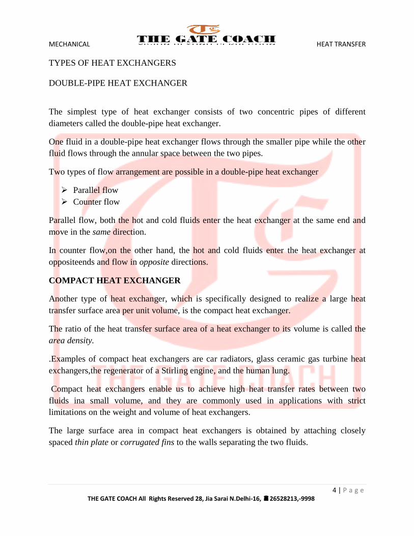
TYPES OF HEAT EXCHANGERS
DOUBLE-PIPE HEAT EXCHANGER
The simplest type of heat exchanger consists of two concentric pipes of different
diameters called the double-pipe heat exchanger.
One fluid in a double-pipe heat exchanger flows through the smaller pipe while the other
fluid flows through the annular space between the two pipes.
Two types of flow arrangement are possible in a double-pipe heat exchanger
Parallel flow
Counter flow
Parallel flow, both the hot and cold fluids enter the heat exchanger at the same end and
move in the same direction.
In counter flow,on the other hand, the hot and cold fluids enter the heat exchanger at
oppositeends and flow in opposite directions.
COMPACT HEAT EXCHANGER
Another type of heat exchanger, which is specifically designed to realize a large heat
transfer surface area per unit volume, is the compact heat exchanger.
The ratio of the heat transfer surface area of a heat exchanger to its volume is called the
area density.
.Examples of compact heat exchangers are car radiators, glass ceramic gas turbine heat
exchangers,the regenerator of a Stirling engine, and the human lung.
Compact heat exchangers enable us to achieve high heat transfer rates between two
fluids ina small volume, and they are commonly used in applications with strict
limitations on the weight and volume of heat exchangers.
The large surface area in compact heat exchangers is obtained by attaching closely
spaced thin plate or corrugated fins to the walls separating the two fluids.

MECHANICAL HEAT TRANSFER
5 | P a g e THE GATE COACH All Rights Reserved 28, Jia Sarai N.Delhi-16, 26528213,-9998
Compact heat exchangers are commonly used in gas-to-gas and gas-to liquid (or liquid-
to-gas) heat exchangers to counteract the low heat transfer coefficient associated with gas
flow with increased surface area.
In compact heat exchangers, the two fluids usually move perpendicular to each other,
and such flow configuration is called cross-flow.
The cross-flow is further classified as
unmixed and
mixed flow, depending on the flow configuration,
The cross-flow is said to be unmixed since the plate fins force the fluid to flow through a
particular interfinspacing and prevent it from moving in the transverse direction (i.e.,
parallel tothe tubes).
The cross-flow is said to be mixed since the fluid now is freeto move in the transverse
direction. Both fluids are unmixed in a car radiator.
The presence of mixing in the fluid can have a significant effect on the heat transfer
characteristics of the heat exchanger.
SHELL-AND-TUBE HEAT EXCHANGER
Shell-and-tubeheat exchangers contain a large number of tubes (sometimes several
hundred)packed in a shell with their axes parallel to that of the shell.
Heat transfer takes place as one fluid flows inside the tubes while the other fluid flows
outside the tubes through the shell.
Baffles are commonly placed in the shell to force the shell-side fluid to flow across the
shell to enhance heat transfer and to maintain uniform spacing between the tubes.
Despite their widespread use, shell and- tube heat exchangers are not suitable for use in
automotive and aircraft applications because of their relatively large size and weight.
The tubes in a shell-and-tube heat exchanger open to some large flow areas called
headers at both ends of the shell, where the tube-side fluid accumulates before entering
the tubes and after leaving them.
Shell-and-tube heat exchangers are further classified according to the number of shell and
tube passes involved.

MECHANICAL HEAT TRANSFER
6 | P a g e THE GATE COACH All Rights Reserved 28, Jia Sarai N.Delhi-16, 26528213,-9998
Heat exchangers in which all the tubes make one U-turn in the shell, for example, are
called one-shell-pass and twotubes-passes heat exchangers.
Likewise, a heat exchanger that involves twopasses in the shell and four passes in the
tubes is called a two-shell-passes andfour-tube-passes heat exchanger
PLATE AND FRAME HEAT EXCHANGER
An innovative type of heat exchanger that has found widespread use is the plate and
frame heat exchanger, which consists of a series of plates with corrugated flat flow
passages
The hot and cold fluids flow in alternate passages and thus each cold fluid stream is
surrounded by two hot fluid streams, resulting in very effective heat transfer. Also, plate
heat exchangers can grow with increasing demand for heat transfer by simply mounting
more plates.
They are well suited for liquid-to-liquid heats exchangeapplications, provided that the
hot and cold fluid streams are at about the same pressure.
REGENERATIVE HEAT EXCHANGER
Another type of heat exchanger that involves the alternate passage of the hot and cold
fluid streams through the same flow area is the regenerative heat exchanger.
The static-type regenerative heat exchanger is basically a porous mass that has a large
heat storage capacity, such as a ceramic wire mesh.
Hot and cold fluids flow through this porous mass alternatively. Heat is transferred from
the hot fluid to the matrix of the regenerator during the flow of the hot fluid, and from the
matrix to the cold fluid during the flow of the cold fluid.
Thus, the matrix serves as a temporary heat storage medium
The dynamic-type regenerator involves a rotating drum and continuous flow of the hot
and cold fluid through different portions of the drum so that any portion of the drum
passes periodically through the hot stream, storing heat,and then through the cold stream,
rejecting this stored heat.
Again the drum serves as the medium to transport the heat from the hot to the cold fluid
stream.

MECHANICAL HEAT TRANSFER
7 | P a g e THE GATE COACH All Rights Reserved 28, Jia Sarai N.Delhi-16, 26528213,-9998
Heat exchangers are often given specific names to reflect the specific application for
which they are used.
For example, a condenser is a heat exchanger in which one of the fluids is cooled and
condenses as it flows through the heat exchanger.
A boiler is another heat exchanger in which one of the fluids absorbs heat and vaporizes.
A space radiator is a heat exchanger that transfers heat from the hot fluid to the
surrounding space by radiation.
THE OVERALL HEAT TRANSFER COEFFICIENT
A heat exchanger typically involves two flowing fluids separated by a solidwall. Heat is
first transferred from the hot fluid to the wall by convection,through the wall by
conduction, and from the wall to the cold fluid again by convection. Any radiation effects
are usually included in the convection heattransfer coefficients.
The thermal resistance network associated with this heat transfer process involves two
convection and one conduction resistances,
Equating both
Here U is called overall heat transfer coefficient.
For heat transfer through a cylindtical wall
Where

MECHANICAL HEAT TRANSFER
8 | P a g e THE GATE COACH All Rights Reserved 28, Jia Sarai N.Delhi-16, 26528213,-9998
When the tube is finned on one side to enhance heat transfer, the total heat transfer area
on the finned side becomes
The effective surface area can be estimated from
FOULING FACTOR
The performance of heat exchangers usually deteriorates with time as a result of
accumulation of deposits on heat transfer surfaces. The layer of deposits represents
additional resistance to heat transfer and causes the rate of heat transfer in a heat
exchanger to decrease.
The net effect of these accumulations on heat transfer is represented by a fouling factor
Rf, which is a measure of the thermal resistance introduced by fouling.
The most common type of fouling is the precipitation of solid deposits in a fluid on the
heat transfer
The solid ash particles in the flue accumulating on the surfaces of air preheaters create
similar problems.
Another form of fouling, which is common in the chemical process industry, is corrosion
and other chemical fouling.
In this case, the surfaces are fouled by the accumulation of the products of chemical
reactions on the surfaces.

MECHANICAL HEAT TRANSFER
9 | P a g e THE GATE COACH All Rights Reserved 28, Jia Sarai N.Delhi-16, 26528213,-9998
This form of fouling can be avoided by coating metal pipes with glassor using plastic
pipes instead of metal ones. Heat exchangers may also befouled by the growth of algae in
warm fluids. This type of fouling is called biological fouling and can be prevented by
chemical treatment.
In applications where it is likely to occur, fouling should be considered in the design and
selection of heat exchangers. In such applications, it may benecessary to select a larger
and thus more expensive heat exchanger to ensure that it meets the design heat transfer
requirements even after fouling occurs.
The periodic cleaning of heat exchangers and the resulting down time are additional
penalties associated with fouling.
The fouling factor is obviously zero for a new heat exchanger and increaseswith time as
the solid deposits build up on the heat exchanger surface. The fouling factor depends on
the operating temperature and the velocity of the fluids, as well as the length of service.
Fouling increases with increasing temperatureand decreasing velocity.
The overall heat transfer coefficient relation given above is valid for clean surfaces and
needs to be modified to account for the effects of fouling on both the inner and the outer
surfaces of the tube.
After a period of operation of heat exchangers, scales are formed on the walls of heat
exchangers which also offer resistance.
Hence to calculate overall heat transfer coefficient, these resistances are needed to be
considered.
are the scale heat transfer coefficients and is overall heat transfer
coefficient with the scaled surfaces.
The reciprocal of the scale heat transfer coefficient is called the fouling factor.
ANALYSIS OF HEAT EXCHANGERS

MECHANICAL HEAT TRANSFER
10 | P a g e THE GATE COACH All Rights Reserved 28, Jia Sarai N.Delhi-16, 26528213,-9998
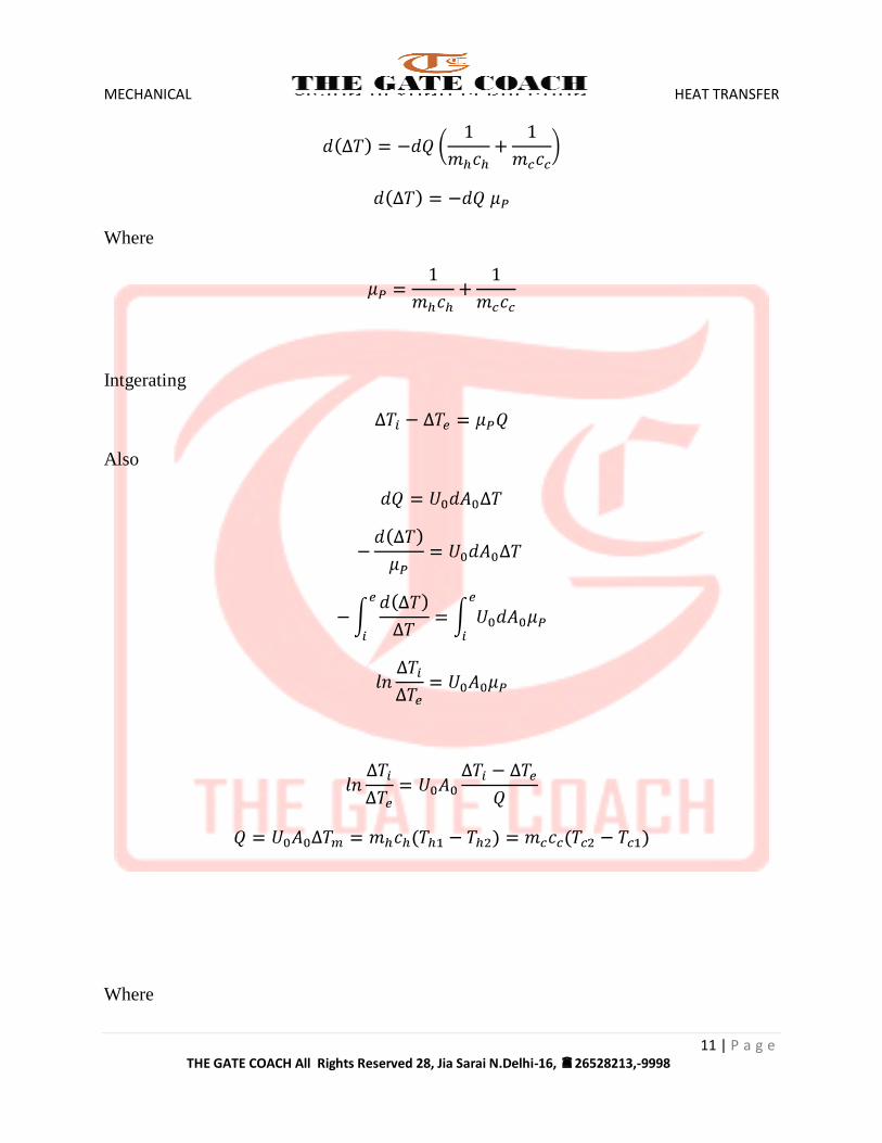
PARALLEL FLOW HEAT EXCHANGER
MECHANICAL HEAT TRANSFER
11 | P a g e THE GATE COACH All Rights Reserved 28, Jia Sarai N.Delhi-16, 26528213,-9998
Where
Intgerating
Also
Where

MECHANICAL HEAT TRANSFER
12 | P a g e THE GATE COACH All Rights Reserved 28, Jia Sarai N.Delhi-16, 26528213,-9998
And is called as logarithmic mean temperature difference (LMTD)
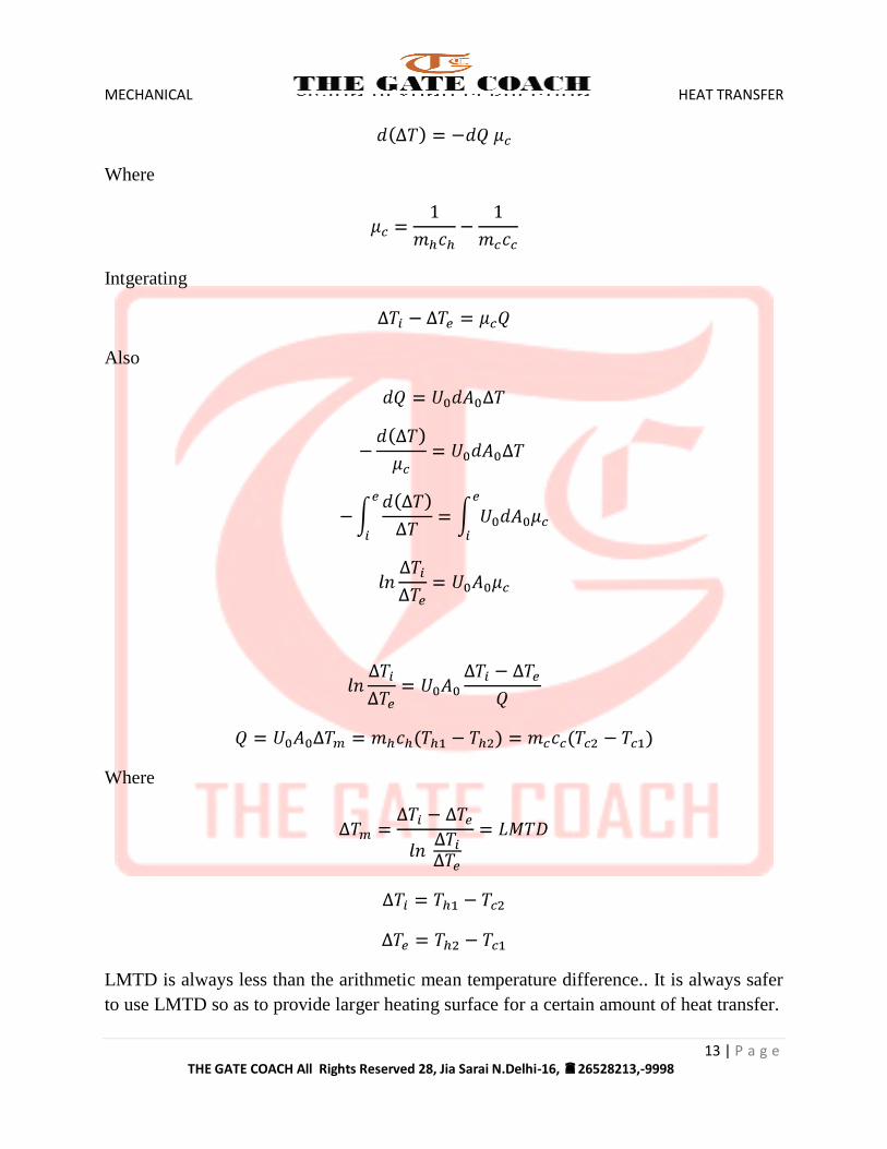
COUNTER FLOW HEAT EXCHANGER
MECHANICAL HEAT TRANSFER
13 | P a g e THE GATE COACH All Rights Reserved 28, Jia Sarai N.Delhi-16, 26528213,-9998
Where
Intgerating
Also
Where
LMTD is always less than the arithmetic mean temperature difference.. It is always safer
to use LMTD so as to provide larger heating surface for a certain amount of heat transfer.

MECHANICAL HEAT TRANSFER
14 | P a g e THE GATE COACH All Rights Reserved 28, Jia Sarai N.Delhi-16, 26528213,-9998
If
Then
CROSS-FLOW HEAT EXCHANGERS
A cross-flow single pass exchanger with plate fins and both fluid unmixed.
COMPARISION OF PARALLEL FLOW AND COUNTER FLOW HEAT
EXCHANGERS
For same inlet and exit temperature of the two fluids, it is found that LMTD for
counterflow is always greater than parallel flow.
For same heat transfer Q and same overall heat transfer coefficient , the surface area
required for counter flow is always less than that for parallel flow.
In parallel flow heat exchangers,
Hot fluid cannot be cooled below a temperature than the cold fluid temperature.
In counter flow heat exchangers, can become less than or can become higher
than i.e. hot fluid can be cooled below cold fluid temperature or the cold fluid can be
heated above hot fluid temperature.
The counter flow heat exchangers are more common in use for industrial purpose.
HEAT TRANSFER WITH PHASE CHANGE
When one of the fluids undergoes phase change, the direction of two fluids is of no use
and LMTD remains the same for all kind of arrangements.
MULTIPASS HEAT EXCHANGERS
MECHANICAL HEAT TRANSFER
15 | P a g e THE GATE COACH All Rights Reserved 28, Jia Sarai N.Delhi-16, 26528213,-9998
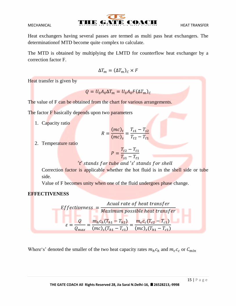
Heat exchangers having several passes are termed as multi pass heat exchangers. The
determinationof MTD become quite complex to calculate.
The MTD is obtained by multiplying the LMTD for counterflow heat exchanger by a
correction factor F.
Heat transfer is given by
The value of F can be obtained from the chart for various arrangements.
The factor F basically depends upon two parameters
1. Capacity ratio
2. Temperature ratio
Correction factor is applicable whether the hot fluid is in the shell side or tube
side.
Value of F becomes unity when one of the fluid undergoes phase change.
EFFECTIVENESS
Where‘s’ denoted the smaller of the two heat capacity rates and or

MECHANICAL HEAT TRANSFER
16 | P a g e THE GATE COACH All Rights Reserved 28, Jia Sarai N.Delhi-16, 26528213,-9998
The maximum possible heat transfer depends on one of the fluids undergoing the
maximum possible change in temperature and that will be the fluid which will have the
minimum value of heat capacity rate.
If fluid with larger heat capacity rate is allowed to go through maximum temperature
difference
Then
becomes greater than , which is impossible since
Case I
If
Case II
If
Heat capacity ratio
If
MECHANICAL HEAT TRANSFER
17 | P a g e THE GATE COACH All Rights Reserved 28, Jia Sarai N.Delhi-16, 26528213,-9998
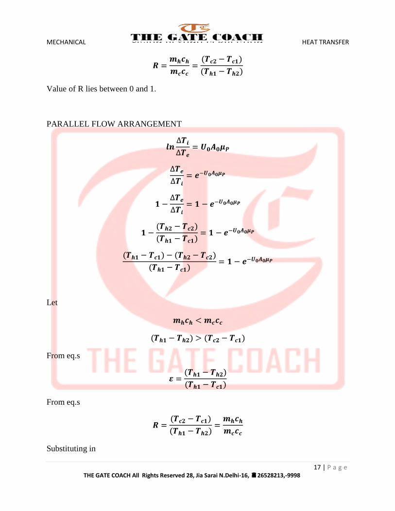
Value of R lies between 0 and 1.
PARALLEL FLOW ARRANGEMENT
Let
From eq.s
From eq.s
Substituting in
MECHANICAL HEAT TRANSFER
18 | P a g e THE GATE COACH All Rights Reserved 28, Jia Sarai N.Delhi-16, 26528213,-9998
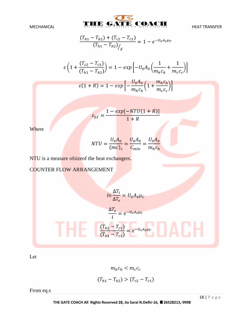
Where
NTU is a measure ofsizeof the heat exchangers.
COUNTER FLOW ARRANGEMENT
Let
From eq.s
MECHANICAL HEAT TRANSFER
19 | P a g e THE GATE COACH All Rights Reserved 28, Jia Sarai N.Delhi-16, 26528213,-9998
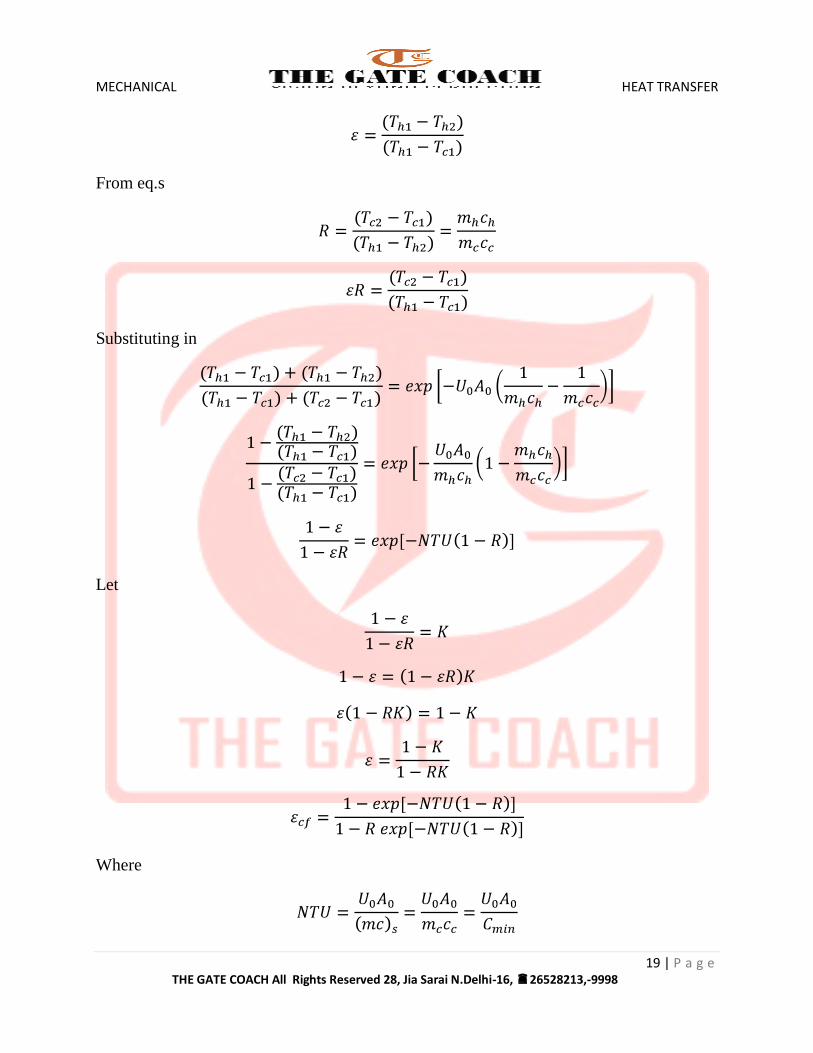
From eq.s
Substituting in
Let
Where

MECHANICAL HEAT TRANSFER
20 | P a g e THE GATE COACH All Rights Reserved 28, Jia Sarai N.Delhi-16, 26528213,-9998
NTU is a measure of size of the heat exchangers.
EXAMPLE 5.1
In an oil cooler, oil enters at 1600C. If water entering at 35
0C flows parallel to oil, the exit
temperatures of oil and water are 900C and 70
0C respectively. Determine the exit
temperatures of oil and water if the two fluids flow in opposite directions. Assume the
flow rates of the two fluids and U0 remains unaltered. What would be minimum
temperatures to which oil could be cooled in parallel flow and counter-flow operations?
SOLUTION
Heat capacity ratio
For parallel flow operation
But also

MECHANICAL HEAT TRANSFER
21 | P a g e THE GATE COACH All Rights Reserved 28, Jia Sarai N.Delhi-16, 26528213,-9998
Since in counterflow operation, remains the same and flow rates also do not
change,NTU will remains the same as in parallel flow operation.
Again R = 0.5
Minimum oil temperature
Minimum oil temperature can be estimated for parallel flow operation by assuming that it
would occur if the heat exchanger were infinitely large or
i.e.

MECHANICAL HEAT TRANSFER
22 | P a g e THE GATE COACH All Rights Reserved 28, Jia Sarai N.Delhi-16, 26528213,-9998
For counter-flow operation, the minimum exit temperature of oil would be 350C when
and
EXAMPLE
In a concentric tube heat exchanger, cold water is heated by steam condensation. The
waterenters the tube at 100C and leaves at 50
0C. The steam pressure is maintained at
1.01325 bar. If the length of the tube isincreased to three times, what would be the outlet
temperature of water? Assume overall heat transfer coefficient is constant for both for
both the cases. Specific heat of water = 4.187 J/Kg-K.
SOLUTION
For phase change process
Effectiveness of heat exchanger is given by
Solving the equation gives
Increasing the length 3 times increases the NTU 3times.
Effectiveness in this case will be given as
Also

MECHANICAL HEAT TRANSFER
23 | P a g e THE GATE COACH All Rights Reserved 28, Jia Sarai N.Delhi-16, 26528213,-9998
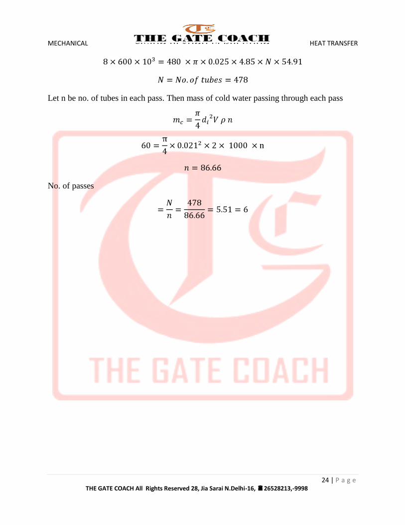
EXAMPLE
Aheat exchanger is to be designed to condense 8 kg/s of an organic fluid (tsat = 800C, hfg
= 600 kJ/kg) with cooling water available at 150C and at a flow rate 0f 60 Kg/s. The
overall heat transfer coefficient is 480 W/m2-deg. Calculate:
a. The no. of tubes required. The tubes are to be of 25 mm outer diameter, 2mm
thickness and 4.85 mm length.
b. The no. of tube passes. The velocity of cooling water is not exceeded 2 m/s.
SOLUTION
From energy balance
Heat lost by vapour = Heat gained by water
LMTD
Heat transfer rate is given by
MECHANICAL HEAT TRANSFER
24 | P a g e THE GATE COACH All Rights Reserved 28, Jia Sarai N.Delhi-16, 26528213,-9998
Let n be no. of tubes in each pass. Then mass of cold water passing through each pass
No. of passes