mechanical engineering capstone 2014-15 project list · pdf filemechanical engineering...
TRANSCRIPT
ME 189 2014-15 Page 1 of 53 Candidate Design Projects
Mechanical Engineering Capstone 2014-15 Project List – 9/29/14
Contents
Introduction .............................................................................................................................................. 2
Project selection ........................................................................................................................................ 2
Questions about projects ........................................................................................................................... 2
Industry Partnered Projects ....................................................................................................................... 3
1. Airfoil modeling and wind tunnel testing – Northrop Grumman ......................................... 3
2. Advanced heat pipe design and testing – Northrop Grumman............................................. 5
3. Kapton Applicator for Slotted Waveguide Antennas - ATK ............................................... 7
4. Stabilized Gimbal for Drone-Mounted Cameras - FLIR .................................................... 12
5. Firefighter Head-mounted Augmented Reality - FLIR ..................................................... 15
6. Cleanroom Tooling for Infrared Device Handling - Raytheon .......................................... 18
7. Hydrocephalus Shunt Improvements - Medtronic ............................................................. 20
8. Eye Model Test System for Intraocular Lenses – Advanced Vision Science .................... 23
9. Counter-top lemon juicer for quick-serve restaurants - Limoneria .................................... 25
10. Cottage Hospital Sponsored Project - Withdrawn ............................................................. 27
Research Lab Partnered Projects ............................................................................................................ 28
11. Advanced filtration test instrumentation - Pennathur ......................................................... 28
12. Adaptive Molds for Precision Far IR Optics – Lubin ........................................................ 31
13. Microfluidic interface bonding tool – Microfluidics Lab .................................................. 33
14. Automated system for degassing and curing microfluidic devices – Microfluidics Lab ... 34
15. Magnetic Tweezers with Oscillating Field Strength – Valentine ....................................... 35
16. Withdrawn - Vacuum deposition tool for microfluidic surface coatings – Microfluidics Lab
............................................................................................................................................ 37
17. Pollutant Removal using Magnetic Nano-particles - Keller ............................................. 38
18. Lens Design and Fabrication for THz Applications – Sherwin ......................................... 39
19. 3-D Calibration for Advanced Strain Mapping System – Zok ........................................... 41
Other Projects ......................................................................................................................................... 42
20. Human Powered Concrete Mixer – African Sky and EWB ............................................... 42
21. Human Powered Vehicle Competition - Bike .................................................................... 45
22. Withdrawn - Human Powered Vehicle Competition - Fairing ........................................... 46
23. Soft Robotics for Materials Science Education .................................................................. 47
24. High Density Modular Storage Unit .................................................................................. 49
25. (NEW!) Satellite Latching Mechanism – Northrop-Grumman .......................................... 50
26. (NEW!) Autonomous Oceanographic Research Vessel – Washburn Lab ......................... 52
ME 189 2014-15 Page 2 of 53 Candidate Design Projects
Introduction This is a list of the candidate projects available for Mechanical Engineering students enrolled in ME189.
As you will see, there is a tremendous range of projects from most of the key areas in which mechanical
engineers work. Some of the projects will require a lot of analysis and minimal fabrication – for others the
balance is reversed.
We expect to have 18 projects this year. In the ideal world the students in ME189 would organize
themselves into teams, and each team’s first choice would be different. The teaching team will do its best
to match students and projects.
The first step is for every student to identify their top three choices. You will be able to see who is
interested in which projects, so that you can work together to setup teams of five students.
Project selection You can access the project preference form on-line at the link below – you will need to login with your
UCSBnet ID.:
https://www.engr.ucsb.edu/me/projects/election/projects.php
During the first class meeting (10/6/14 @ 10am in Buchanan 1930) we’ll go over all of the candidate
projects and at the end of that week each team will identify it’s project preferences
Questions about projects If you have any questions about these projects please e-mail Dave Bothman and Steve Laguette by e-
mailing me-capstone.engineering.ucsb.edu
ME 189 2014-15 Page 3 of 53 Candidate Design Projects
Industry Partnered Projects
Airfoil modeling and wind tunnel testing – Northrop Grumman
Project adviser: TBD
Questions: E-mail me-capstone.engineering.ucsb.edu
Customer contact information: TBD
Sponsor information: This project is in cooperation and partnership under a gift with Northrop
Grumman Corporation (NGC) located in Redondo Beach, California. NGC Project Lead – Phil Barnes.
Northrup Grumman Project Name: Passive “bleed and blow” airfoil wind tunnel test
NGC is a $30 billion global defense and technology company whose 120,000 employees provide
innovative systems, products, and solutions in information and services, electronics, aerospace and
shipbuilding to government and commercial customers worldwide.
NGC is a premier developer, integrator, producer and supporter of manned and unmanned aircraft,
spacecraft, high-energy laser systems, microelectronics and other systems and subsystems critical to
maintaining the nation’s security and leadership in science and technology. These systems are used,
primarily by government customers, in many different mission areas including intelligence, surveillance
and reconnaissance; communications; battle management; strike operations; electronic warfare; missile
defense; earth observation; space science; and space exploration.
NGC develops a broad range of systems at the leading edge of space, defense and electronics technology.
Building on a heritage of innovation, we create sophisticated products that contribute significantly to the
nation's security and leadership in science and technology.
Background: An airfoil has different pressures around its surface, ranging from “ram” at the stagnation
point to strong suction shortly downstream on the upper surface. Also along the upper surface, strong
“curvature” effects are manifest between 40 and 70% chord at high-lift conditions. The “passive bleed
and blow” airfoil, to be tested in a low-speed wind tunnel, would have a row of holes drilled at some
upstream location, with the optimum thereof determined by test, and another row of holes to either bleed
or blow at perhaps 70% chord on the upper surface. Depending on angle of attack and hole location, the
two row of holes will exhibit bi-directional recirculation which may (or may not) enhance
lift and/or reduce drag at high lift conditions, without the need to externally provide high-pressure air.
Objectives: The objectives of the project would include testing a representative low-speed airfoil with
various upstream hole locations over a range of angles of attack to compare the lift and drag polar to a
baseline “clean” airfoil. Although an airfoil is largely a 2D entity, the potential benefits of “bleed and
blow” can be expected to be 3D, should such benefits exist. Accordingly, any related CFD studies, if
applicable, should be 3D. The success criterion for the project is to capture and document the effect, if
any, of the “bleed and blow” concept for the chosen conditions, with or without yielding improved airfoil
performance.
Research the literature
Conduct CFD studies if applicable

ME 189 2014-15 Page 4 of 53 Candidate Design Projects
Brainstorm the test article configurations and test matrix
Fabricate the airfoil test articles and measurands, perhaps including flow visualization
Conduct the test and document the results
Additional information:
Design/Result Expectations: Test data is obtained and documented to show the effects of “bleed and
blow” on airfoil aerodynamic characteristics relative to a baseline “clean” airfoil
The company requires US citizenship for all site visits and a Confidential Disclosure Agreement.
Students with an interest in mechanisms and mechanical systems and an interest in the aerospace industry
will find this project demanding and technically challenging.
This project may require travel to company facility and may require periodic teleconferences.
Website: www.northropgrumman.com/index.html
ME 189 2014-15 Page 5 of 53 Candidate Design Projects
Advanced heat pipe design and testing – Northrop Grumman
Project adviser: TBD
Questions: E-mail me-capstone.engineering.ucsb.edu
Customer contact information: TBD
Sponsor information: This project is in cooperation and partnership under a gift with Northrop
Grumman Corporation (NGC) located in Redondo Beach, California. NGC Project Lead – Clint
Buckman. Northrop Grumman’s project title is: Variable conductance miniaturized vapor chamber
NGC is a $30 billion global defense and technology company whose 120,000 employees provide
innovative systems, products, and solutions in information and services, electronics, aerospace and
shipbuilding to government and commercial customers worldwide.
NGC is a premier developer, integrator, producer and supporter of manned and unmanned aircraft,
spacecraft, high-energy laser systems, microelectronics and other systems and subsystems critical to
maintaining the nation’s security and leadership in science and technology. These systems are used,
primarily by government customers, in many different mission areas including intelligence, surveillance
and reconnaissance; communications; battle management; strike operations; electronic warfare; missile
defense; earth observation; space science; and space exploration.
NGC develops a broad range of systems at the leading edge of space, defense and electronics technology.
Building on a heritage of innovation, we create sophisticated products that contribute significantly to the
nation's security and leadership in science and technology.
Background: It is critical that thermal excursions are minimized for reliable life of spacecraft
electronics. This is particular challenging for Low earth orbit missions, where the electronics are often
power cycled in addition to the orbital variation the electronics will see. As a potential mitigation, we
would like to see concept development of miniaturized variable conductance vapor chambers (aka,
planar heat pipes).
Would like to see various design approaches toward making the conductance of a vapor chamber
vary from 2C/W at 40C, to 4.5C/W at 15C . (less rise is acceptable, so long as the variation scales
from low to high at the same ratio). Ideal solution will scale linearly through given range.
A size envelope will be provided. Would prefer naturally occurring phenomenon to govern the
variation, but electronic control systems are also a strong possibility. If electronic control is required,
the entire control system does not have to be designed, but at least conceptually thought out.
Objectives:
Design of vapor chamber capable of varying conductance from 2C/W at 40C, to 4.5C/W at
15C . Less thermal resistance is acceptable, so long as the variation scales from low to high at
the same ratio.
We will expect final design review, including the following:
o concept drawings and analysis proving design applicable
o tolerance studies
o bill of materials.

ME 189 2014-15 Page 6 of 53 Candidate Design Projects
Additional information:
The company requires US citizenship for all site visits and a Confidential Disclosure Agreement.
Students with an interest in mechanisms and mechanical systems and an interest in the aerospace industry
will find this project demanding and technically challenging.
This project may require travel to company facility and may require periodic teleconferences.
Website: www.northropgrumman.com/index.html

ME 189 2014-15 Page 7 of 53 Candidate Design Projects
Kapton Applicator for Slotted Waveguide Antennas - ATK
Project adviser: TBD
Questions: E-mail me-capstone.engineering.ucsb.edu
Customer contact information: TBD
Sponsor information: This project is in cooperation and partnership under a gift with ATK Space
Systems located in Goleta. ATK Space Systems in Goleta is a leading producer of deployable space
systems. Products include deployable Booms, Solar Arrays, and Stable Structures and Antennas. With
over 70 successful Spaceflight Missions, detailed assembly processes and rigorous testing in simulated
space environments are key elements in maintaining our 100% mission success. Current programs include
the CRS Ultraflex Solar Arrays, NASA Mars Insight, NASA Megaflex Solar Arrays as well as radar
antennas for the Canadian CP-140 maritime patrol aircraft.
Background:
Over the last several years, ATK has been successful in developing and delivering a number of slotted
waveguide array antennas for various airborne radar systems. These antennas are made from machined
and brazed aluminum, and characterized by their flat radiating surface and their many rows of radiating
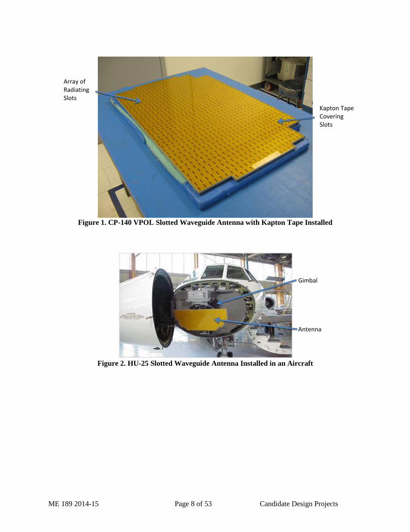
slots. A typical radiating surface is shown in Figure 1. High-power RF electromagnetic radiation passes
through the input port of the antenna during both transmit and receive. The antenna’s waveguide feed
network divides and distributes the energy across the radiating surface so that each individual slot works
together the others in an array to create a highly directive beam, meaning the antenna is very efficient in
sending or receiving energy in one specific direction perpendicular to the radiating surface. On the
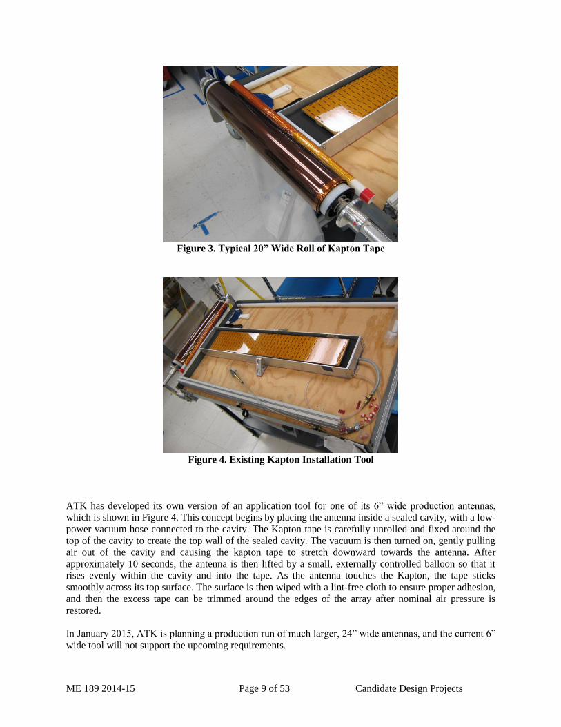
aircraft, the antenna is rotated on a gimbal to cover a wide field of view. The radar system maintains
precise control of the antenna’s pointing angle so that any received signal can be directly correlated with
an angular position relative to the aircraft, and so that the pilot and crew can be aware of the surrounding
environment. A picture of an antenna installed on an aircraft is provided in Figure 2.
A critical characteristic of these antennas is their ability to survive harsh environments for long periods of
operating and storage time. These environments provide all sorts of challenges to maintaining proper
electrical performance, such as high altitudes, hot and cold temperatures (-55° C to +71° C typ.),
humidity, fungus, salt spray, sand and dust, along with all the contaminating fluids common in an aircraft
hangar, such as jet fuel, oil, solvents, and grease. In order to protect the internal waveguide structure of
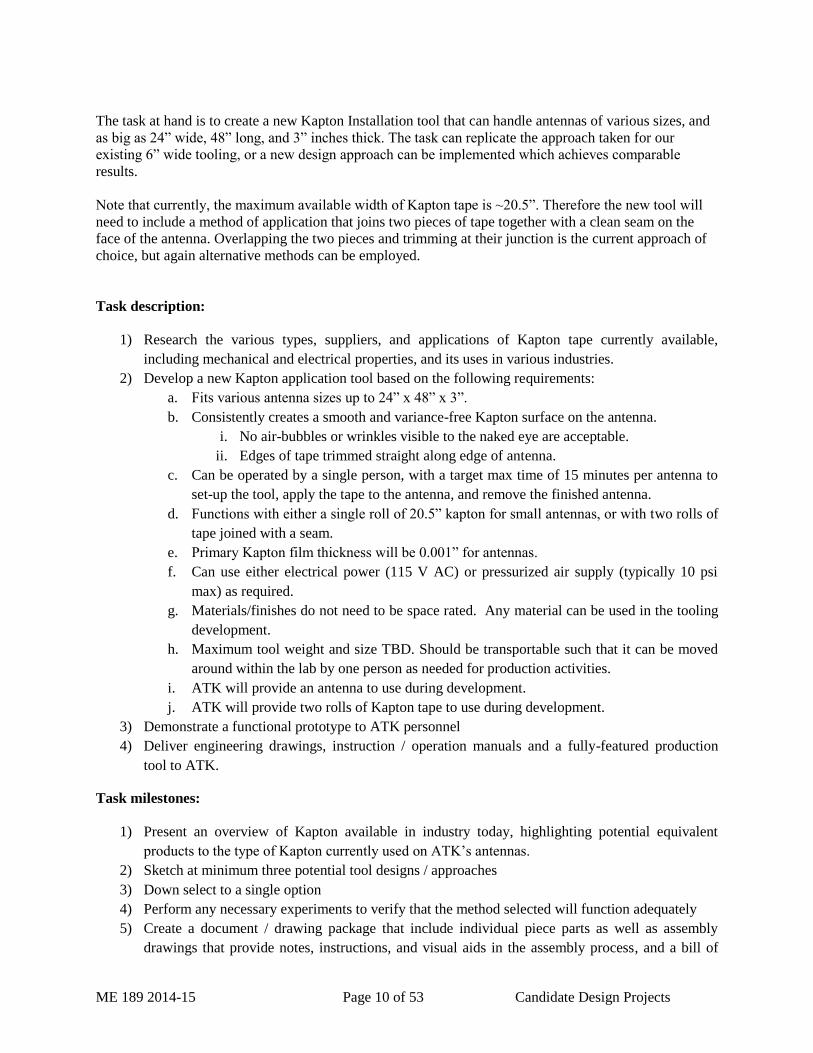
the antenna from these environmental challenges, the radiating surface of the antenna is covered by a
wide sheet of Kapton tape. This tape provides both a pressure seal and the necessary barrier for proper
protection. A photo of a typical roll of Kapton tape is provided in Figure 3.
The radiating slots on the antennas are designed and tuned to work with a very specific type of Kapton
tape, which is only 1 mil thick. This thickness causes the application process to be very challenging, since
the tape has a tendency to fold or tear easily, and to trap tiny air bubbles against the aluminum surface of
the antenna. However proper application is critical, as any deviations could potentially cause a failure in
seal, pressurization or an electrical malfunction in the antenna. Therefore the team at ATK would benefit
greatly from the development of a new tool that could simplify and improve the process of installing
Kapton tape on its large slotted waveguide antennas.
ME 189 2014-15 Page 8 of 53 Candidate Design Projects
Figure 1. CP-140 VPOL Slotted Waveguide Antenna with Kapton Tape Installed
Figure 2. HU-25 Slotted Waveguide Antenna Installed in an Aircraft
Array of Radiating Slots
Kapton Tape Covering Slots
Antenna
Gimbal
ME 189 2014-15 Page 9 of 53 Candidate Design Projects
Figure 3. Typical 20” Wide Roll of Kapton Tape
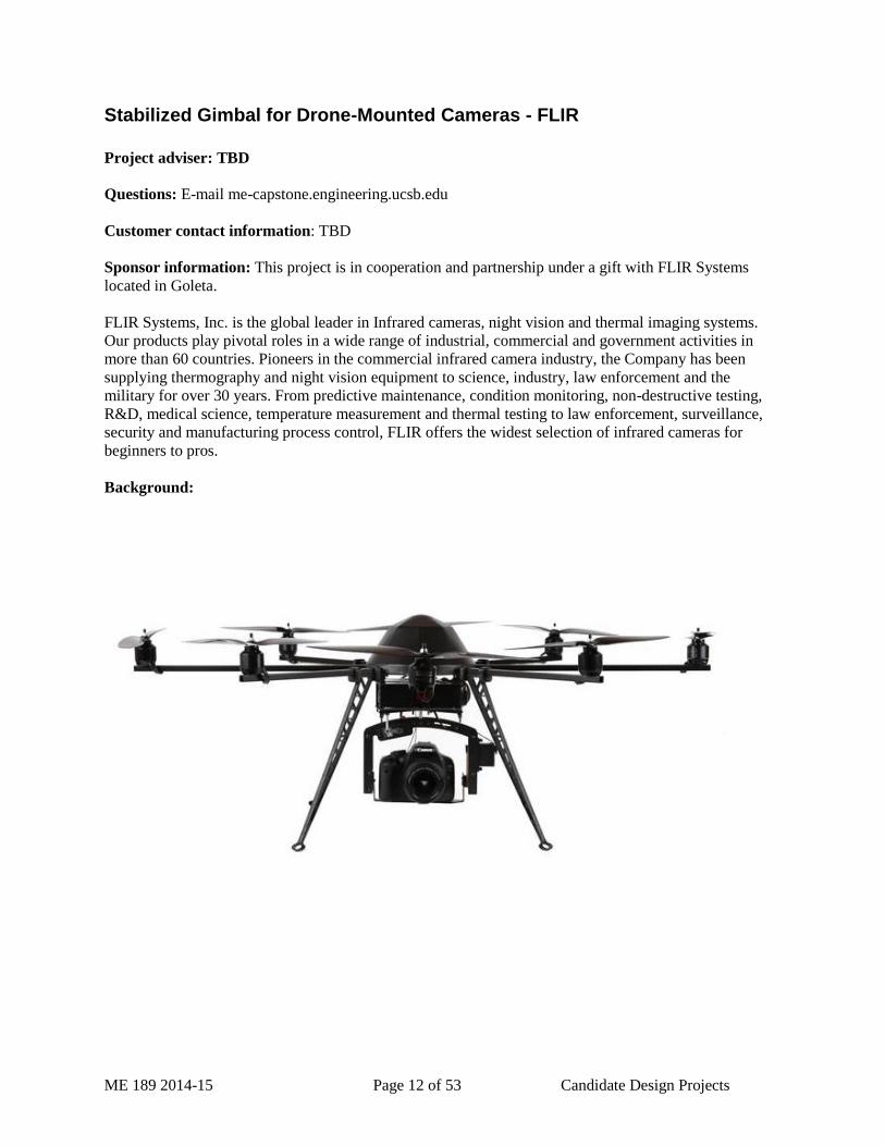
Figure 4. Existing Kapton Installation Tool
ATK has developed its own version of an application tool for one of its 6” wide production antennas,
which is shown in Figure 4. This concept begins by placing the antenna inside a sealed cavity, with a low-
power vacuum hose connected to the cavity. The Kapton tape is carefully unrolled and fixed around the
top of the cavity to create the top wall of the sealed cavity. The vacuum is then turned on, gently pulling
air out of the cavity and causing the kapton tape to stretch downward towards the antenna. After
approximately 10 seconds, the antenna is then lifted by a small, externally controlled balloon so that it
rises evenly within the cavity and into the tape. As the antenna touches the Kapton, the tape sticks
smoothly across its top surface. The surface is then wiped with a lint-free cloth to ensure proper adhesion,
and then the excess tape can be trimmed around the edges of the array after nominal air pressure is
restored.
In January 2015, ATK is planning a production run of much larger, 24” wide antennas, and the current 6”
wide tool will not support the upcoming requirements.
ME 189 2014-15 Page 10 of 53 Candidate Design Projects
The task at hand is to create a new Kapton Installation tool that can handle antennas of various sizes, and
as big as 24” wide, 48” long, and 3” inches thick. The task can replicate the approach taken for our
existing 6” wide tooling, or a new design approach can be implemented which achieves comparable
results.
Note that currently, the maximum available width of Kapton tape is ~20.5”. Therefore the new tool will
need to include a method of application that joins two pieces of tape together with a clean seam on the
face of the antenna. Overlapping the two pieces and trimming at their junction is the current approach of
choice, but again alternative methods can be employed.
Task description:
1) Research the various types, suppliers, and applications of Kapton tape currently available,
including mechanical and electrical properties, and its uses in various industries.
2) Develop a new Kapton application tool based on the following requirements:
a. Fits various antenna sizes up to 24” x 48” x 3”.
b. Consistently creates a smooth and variance-free Kapton surface on the antenna.
i. No air-bubbles or wrinkles visible to the naked eye are acceptable.
ii. Edges of tape trimmed straight along edge of antenna.
c. Can be operated by a single person, with a target max time of 15 minutes per antenna to
set-up the tool, apply the tape to the antenna, and remove the finished antenna.
d. Functions with either a single roll of 20.5” kapton for small antennas, or with two rolls of
tape joined with a seam.
e. Primary Kapton film thickness will be 0.001” for antennas.
f. Can use either electrical power (115 V AC) or pressurized air supply (typically 10 psi
max) as required.
g. Materials/finishes do not need to be space rated. Any material can be used in the tooling
development.
h. Maximum tool weight and size TBD. Should be transportable such that it can be moved
around within the lab by one person as needed for production activities.
i. ATK will provide an antenna to use during development.
j. ATK will provide two rolls of Kapton tape to use during development.
3) Demonstrate a functional prototype to ATK personnel
4) Deliver engineering drawings, instruction / operation manuals and a fully-featured production
tool to ATK.
Task milestones:
1) Present an overview of Kapton available in industry today, highlighting potential equivalent
products to the type of Kapton currently used on ATK’s antennas.
2) Sketch at minimum three potential tool designs / approaches
3) Down select to a single option
4) Perform any necessary experiments to verify that the method selected will function adequately
5) Create a document / drawing package that include individual piece parts as well as assembly
drawings that provide notes, instructions, and visual aids in the assembly process, and a bill of

ME 189 2014-15 Page 11 of 53 Candidate Design Projects
materials that identifies whether parts will be made or purchased, and at what quantity, price and
lead-time.
6) Acquire the necessary components and tools
7) Build a functional prototype unit, and present the working prototype to ATK personnel.
8) Document any red-lines, lessons learned or product improvements during the prototype phase and
update the drawing package accordingly.
9) Present and deliver a fully-featured production tool that incorporates updates as required.
Additional information:
Students will be required to sign a Confidentiality Agreement and Invention Agreement.
Students are required to be a United States citizen for all facility site visits.
Website: www.atk.com
ME 189 2014-15 Page 12 of 53 Candidate Design Projects
Stabilized Gimbal for Drone-Mounted Cameras - FLIR
Project adviser: TBD
Questions: E-mail me-capstone.engineering.ucsb.edu
Customer contact information: TBD
Sponsor information: This project is in cooperation and partnership under a gift with FLIR Systems
located in Goleta.
FLIR Systems, Inc. is the global leader in Infrared cameras, night vision and thermal imaging systems.
Our products play pivotal roles in a wide range of industrial, commercial and government activities in
more than 60 countries. Pioneers in the commercial infrared camera industry, the Company has been
supplying thermography and night vision equipment to science, industry, law enforcement and the
military for over 30 years. From predictive maintenance, condition monitoring, non-destructive testing,
R&D, medical science, temperature measurement and thermal testing to law enforcement, surveillance,
security and manufacturing process control, FLIR offers the widest selection of infrared cameras for
beginners to pros.
Background:
ME 189 2014-15 Page 13 of 53 Candidate Design Projects
Project Description:
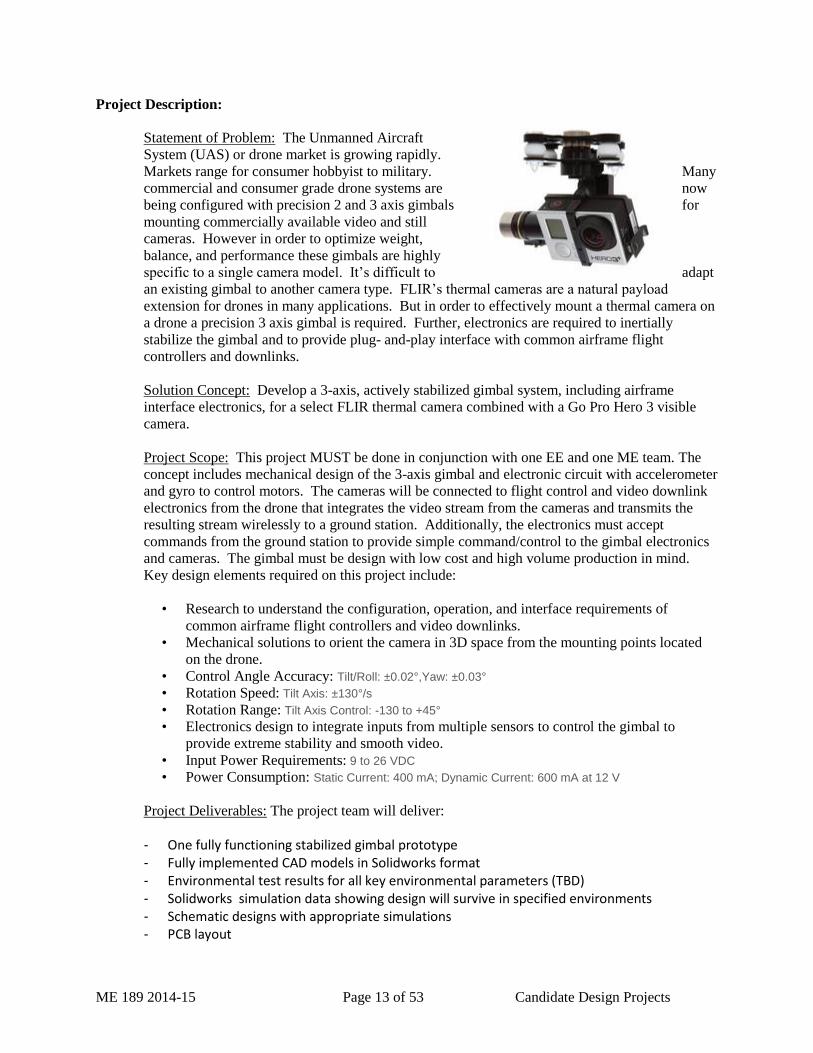
Statement of Problem: The Unmanned Aircraft
System (UAS) or drone market is growing rapidly.
Markets range for consumer hobbyist to military. Many
commercial and consumer grade drone systems are now
being configured with precision 2 and 3 axis gimbals for
mounting commercially available video and still
cameras. However in order to optimize weight,
balance, and performance these gimbals are highly
specific to a single camera model. It’s difficult to adapt
an existing gimbal to another camera type. FLIR’s thermal cameras are a natural payload
extension for drones in many applications. But in order to effectively mount a thermal camera on
a drone a precision 3 axis gimbal is required. Further, electronics are required to inertially
stabilize the gimbal and to provide plug- and-play interface with common airframe flight
controllers and downlinks.
Solution Concept: Develop a 3-axis, actively stabilized gimbal system, including airframe
interface electronics, for a select FLIR thermal camera combined with a Go Pro Hero 3 visible
camera.
Project Scope: This project MUST be done in conjunction with one EE and one ME team. The
concept includes mechanical design of the 3-axis gimbal and electronic circuit with accelerometer
and gyro to control motors. The cameras will be connected to flight control and video downlink
electronics from the drone that integrates the video stream from the cameras and transmits the
resulting stream wirelessly to a ground station. Additionally, the electronics must accept
commands from the ground station to provide simple command/control to the gimbal electronics
and cameras. The gimbal must be design with low cost and high volume production in mind.
Key design elements required on this project include:
• Research to understand the configuration, operation, and interface requirements of
common airframe flight controllers and video downlinks.
• Mechanical solutions to orient the camera in 3D space from the mounting points located
on the drone.
• Control Angle Accuracy: Tilt/Roll: ±0.02°,Yaw: ±0.03°
• Rotation Speed: Tilt Axis: ±130°/s
• Rotation Range: Tilt Axis Control: -130 to +45°
• Electronics design to integrate inputs from multiple sensors to control the gimbal to
provide extreme stability and smooth video.
• Input Power Requirements: 9 to 26 VDC
• Power Consumption: Static Current: 400 mA; Dynamic Current: 600 mA at 12 V
Project Deliverables: The project team will deliver:
- One fully functioning stabilized gimbal prototype - Fully implemented CAD models in Solidworks format - Environmental test results for all key environmental parameters (TBD) - Solidworks simulation data showing design will survive in specified environments - Schematic designs with appropriate simulations - PCB layout
ME 189 2014-15 Page 14 of 53 Candidate Design Projects
- Source code for firmware operating in gimbal
Student Requirements: Team participants will be required to;
- Sign non-disclosure forms with FLIR to limit outside disclosure of certain proprietary information relating to supplied thermal cameras
- Sign agreements that provide FLIR with access to any intellectual property developed during the project
Ideal Student Qualifications:
- Mechanical engineering with emphasis on structural integrity and vibration environments - Electrical engineering with emphasis on embedded processing, sensor interface and circuit
board design. - Algorithm development with emphasis on stabilized systems. - Embedded software with emphasis on Linix-based systems (preferred).
Assets Provided by the Company:
- Drone - Select FLIR thermal camera - Go Pro camera - Access to mechanical, electrical, and systems engineering expertise as required - Access, on as available basis, to environmental test facilities at FLIR
Company Web Site : www.FLIR.com

ME 189 2014-15 Page 15 of 53 Candidate Design Projects
Firefighter Head-mounted Augmented Reality - FLIR
Industry Partner: FLIR Systems, Inc. is the global leader in Infrared cameras, night vision and thermal
imaging systems. Our products play pivotal roles in a wide range of industrial, commercial and
government activities in more than 60 countries. Pioneers in the commercial infrared camera industry, the
Company has been supplying thermography and night vision equipment to science, industry, law
enforcement and the military for over 30 years. From predictive maintenance, condition monitoring, non-
destructive testing, R&D, medical science, temperature measurement and thermal testing to law
enforcement, surveillance, security and manufacturing process control, FLIR offers the widest selection
of infrared cameras for beginners to pros.
ME 189 2014-15 Page 16 of 53 Candidate Design Projects
Project Description:
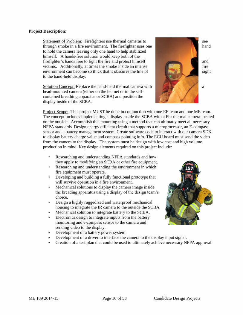
Statement of Problem: Firefighters use thermal cameras to see
through smoke in a fire environment. The firefighter uses one hand
to hold the camera leaving only one hand to help stabilized
himself. A hands-free solution would keep both of the
firefighter’s hands free to fight the fire and protect himself and
victims. Additionally, at times the smoke inside an intense fire
environment can become so thick that it obscures the line of sight
to the hand-held display.
Solution Concept: Replace the hand-held thermal camera with a
head-mounted camera (either on the helmet or in the self-
contained breathing apparatus or SCBA) and position the
display inside of the SCBA.
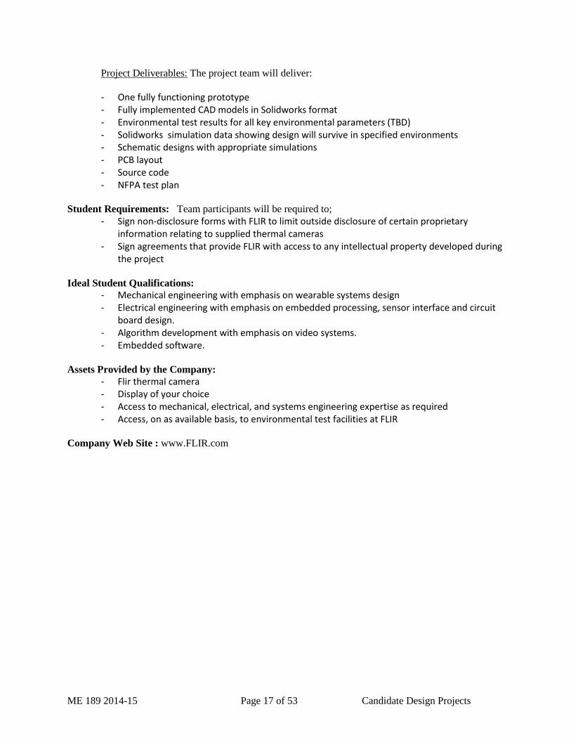
Project Scope: This project MUST be done in conjunction with one EE team and one ME team.
The concept includes implementing a display inside the SCBA with a Flir thermal camera located
on the outside. Accomplish this mounting using a method that can ultimatly meet all necessary
NFPA standards Design energy efficient circuit that supports a microprocessor, an E-compass
sensor and a battery management system. Create software code to interact with our camera SDK
to display battery charge value and compass pointing info. The ECU board must send the video
from the camera to the display. The system must be design with low cost and high volume
production in mind. Key design elements required on this project include:
• Researching and understanding NFPA standards and how
they apply to modifying an SCBA or other fire equipment.
• Researching and understanding the environment in which
fire equipment must operate.
• Developing and building a fully functional prototype that
will survive operation in a fire environment.
• Mechanical solutions to display the camera image inside
the breading apparatus using a display of the design team’s
choice.
• Design a highly ruggedized and waterproof mechanical
housing to integrate the IR camera to the outside the SCBA.
• Mechanical solution to integrate battery to the SCBA.
• Electronics design to integrate inputs from the battery
monitoring and e-compass sensor to the camera and
sending video to the display.
• Development of a battery power system
• Development of a driver to interface the camera to the display input signal.
• Creation of a test plan that could be used to ultimately achieve necessary NFPA approval.
ME 189 2014-15 Page 17 of 53 Candidate Design Projects
Project Deliverables: The project team will deliver:
- One fully functioning prototype - Fully implemented CAD models in Solidworks format - Environmental test results for all key environmental parameters (TBD) - Solidworks simulation data showing design will survive in specified environments - Schematic designs with appropriate simulations - PCB layout - Source code - NFPA test plan
Student Requirements: Team participants will be required to;
- Sign non-disclosure forms with FLIR to limit outside disclosure of certain proprietary information relating to supplied thermal cameras
- Sign agreements that provide FLIR with access to any intellectual property developed during the project
Ideal Student Qualifications:
- Mechanical engineering with emphasis on wearable systems design - Electrical engineering with emphasis on embedded processing, sensor interface and circuit
board design. - Algorithm development with emphasis on video systems. - Embedded software.
Assets Provided by the Company:
- Flir thermal camera - Display of your choice - Access to mechanical, electrical, and systems engineering expertise as required - Access, on as available basis, to environmental test facilities at FLIR
Company Web Site : www.FLIR.com
ME 189 2014-15 Page 18 of 53 Candidate Design Projects
Cleanroom Tooling for Infrared Device Handling - Raytheon
Project adviser: TBD
Questions: E-mail me-capstone.engineering.ucsb.edu
Customer contact information: TBD
Sponsor information: This project is in cooperation with Raytheon Vision Systems, based in Goleta.
Raytheon Vision Systems develops and produces state-of-the-art detection and imaging devices for
applications in the x-ray, visible, infrared, terahertz and millimeter wave regions of the electromagnetic
spectrum. RVS is well regarded as an intellectual and technological development leader. A complex of
buildings that house development laboratories, and class 10,000 to 100 cleanrooms, offices, and
manufacturing facilities provide RVS with world class capability for development and fabrication of top
of the line sensing products. The RVS site, located in Goleta, California, employs approximately 1,000
people with functional organizations engaged in research and development, design engineering, and
manufacturing.
Students will have an opportunity to visit and work closely with industry engineers responsible for the
development of cutting edge next generation technology on site.
Background: RVS’s reputation as a premier world class provider of infrared sensors is in part due to the
unique crystallographic material that is developed, grown and processed on site. This highly specialized
material varies in shape from squares to rectangles and also comes in multiple sizes. Assembly processing
of infrared detectors at RVS includes the handling of infrared detectors, readout chips and sensor chip
hybrids. The purpose of this project is to explore and develop new low cost methods for handling
detectors and sensor chips of various sizes and materials during processing and assembly. Improved die
handling techniques are required to improve cost and manufacturing cycle time efficiencies.
Objectives / Scope:
While working with industry leading engineers, students can expect to gain a solid concept of
basic semiconductor properties, tooling and manufacturing techniques. That understanding will
be critical to the design and fabrication of tooling capable of die handling next generation infrared
detectors.
Tooling will need to be class 100 cleanroom compatible and allow for easy removal and precision
remounting of various size and Lowshape IR sensor chips.
Some key critical considerations for the tooling will be:
o must be must not particulate
o must be electrically conductive or dissipative
o must be ergonomic and must not damage fragile detector material
o Devices may be fabricated using conventional machining, direct digital manufacturing,
laser machining, chemical machining, etc.
Students interested in Manufacturing Engineering, Process Engineering, Industrial Engineering
and the semi-conductor industry should find this project challenging and rewarding.
Additional information:

ME 189 2014-15 Page 19 of 53 Candidate Design Projects
Ideal Student Qualifications:
Ideal candidates will be familiar with mechanical design CAD programs (preferably ProE/Creo), willing
to explore semi conductor processing equipment in a cleanroom environment, be hands on, ready to learn
and capable developing innovative solutions. Students will be expected to interact with Raytheon
engineering on an ongoing basis and visit the site regularly. Familiarity with a cleanroom environment is
helpful but not necessary.
Student Requirements:
US citizenship or permanent resident
Proprietary Information Agreement and Invention Agreement
The students will also need to provide proof of U.S. citizenship such as a copy of a passport or birth
certificate. An electronic pdf copy is fine.
Website: http://www.raytheon.com/businesses/ncs/rvs/index.html
ME 189 2014-15 Page 20 of 53 Candidate Design Projects
Hydrocephalus Shunt Improvements - Medtronic
Project adviser: TBD
Questions: E-mail me-capstone.engineering.ucsb.edu
Customer contact information: TBD
Sponsor information: This project is in cooperation and partnership under a gift with Medtronic
Neurosurgery located in Goleta.
Background: Medtronic Neurosurgery (MNS) is a local medical device company that is a leader in the
field of neurosurgical implants and devices. Medtronic is the global leader in medical technology,
alleviating pain, restoring health and extending life for millions of people around the world. MNS is a
world leader in the design and manufacture of implants and devices intended to treat hydrocephalus.
Hydrocephalus is a buildup of fluid inside the skull that leads to brain swelling. Hydrocephalus means
"water on the brain." Hydrocephalus is due to a problem with the flow of the fluid that surrounds the
brain. This fluid is called the cerebrospinal fluid, or CSF. It surrounds the brain and spinal cord, and helps
cushion the brain. CSF normally moves through the brain and the spinal cord, and is soaked into the
bloodstream. CSF levels in the brain can rise if:
The flow of CSF is blocked
It does not get absorbed into the blood properly
Your brain makes too much of it
Too much CSF puts pressure on the brain. This pushes the brain up against the skull and damage brain
tissue.
Hydrocephalus may begin while the baby is growing in the womb. It is common in babies who have a
myelomeningocele, a birth defect in which the spinal column does not close properly.
Long-term implants known as Shunts have been used to treat hydrocephalus for more than 50 years. The
devices allow excess cerebrospinal fluid to drain to another area of the body. A Shunt usually consists of
two catheters and a one-way valve. The valve regulates the amount, flow direction, and pressure of
cerebrospinal fluid out of the brain’s ventricles. As the pressure of cerebrospinal fluid inside the brain
increases, the one-way valve opens and the excessive fluid drains to the downstream cavity.
ME 189 2014-15 Page 21 of 53 Candidate Design Projects
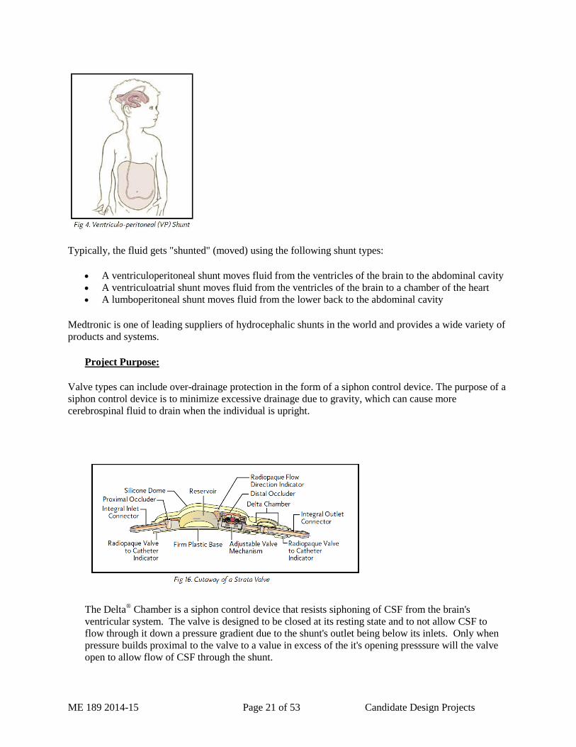
Typically, the fluid gets "shunted" (moved) using the following shunt types:
A ventriculoperitoneal shunt moves fluid from the ventricles of the brain to the abdominal cavity
A ventriculoatrial shunt moves fluid from the ventricles of the brain to a chamber of the heart
A lumboperitoneal shunt moves fluid from the lower back to the abdominal cavity
Medtronic is one of leading suppliers of hydrocephalic shunts in the world and provides a wide variety of
products and systems.
Project Purpose:
Valve types can include over-drainage protection in the form of a siphon control device. The purpose of a
siphon control device is to minimize excessive drainage due to gravity, which can cause more
cerebrospinal fluid to drain when the individual is upright.
The Delta® Chamber is a siphon control device that resists siphoning of CSF from the brain's
ventricular system. The valve is designed to be closed at its resting state and to not allow CSF to
flow through it down a pressure gradient due to the shunt's outlet being below its inlets. Only when
pressure builds proximal to the valve to a value in excess of the it's opening presssure will the valve
open to allow flow of CSF through the shunt.
ME 189 2014-15 Page 22 of 53 Candidate Design Projects
A brief overview of the device and function in the following video:
https://www.youtube.com/watch?v=CT_-qe0j7lY
It is desired to design a protective guard for the Delta Chamber to prevent cuts and damage by
surgical instruments during the handling and implantation of the shunt.
Objectives:
Project Scope:
The project team activities will include the following:
an understanding of shunt performance and performance standards
an understanding of surgical implantation techniques and instruments
an understanding of regulatory and quality requirements
design of shunt implants and selection of materials
testing and evaluation of current products and prototypes
creation of new designs and drawings
fabrication and testing of prototypes
communication and interaction with the sponsor as needed
Expected project deliverables upon completion of the project:
It is desired that the project team complete the following deliverables upon completion of the
project:
At least one design is selected and prototypes fabricated for testing
The prototypes should be to scale but not necessarily implant grade materials
Test Procedures and Test Reports that document device performance
Alternative designs are also desired for review and consideration
A complete drawing package for the selected design
Additional information:
Students interested in the medical industry will find this project interesting and challenging. This is an
opportunity to work with industry engineers, scientists and marketing executives.
Students will be required to sign a Confidentiality Agreement and Invention Agreement.
Website: http://www.medtronic.com and http://www.medtronic.com/our-therapies/hydrocephalus-
products/index.htm
ME 189 2014-15 Page 23 of 53 Candidate Design Projects
Eye Model Test System for Intraocular Lenses – Advanced Vision Science
Project adviser: TBD
Questions: E-mail me-capstone.engineering.ucsb.edu
Customer contact information: TBD
Sponsor information: This project is in cooperation with Advanced Vision Science Inc. (AVS), based in
Goleta, California.
Advanced Vision Science, Inc (AVS) is a medical device company with a global presence. Its core
businesses are research and development and the manufacturing of implantable medical devices including
intraocular lenses (IOLs) for cataract surgery.
Cataract (clouding of the crystalline lens) is currently the leading cause of blindness worldwide.
Treatment consists of a routine surgical intervention that is successfully performed millions of times each
year. During refractive lens exchange surgery, the crystalline lens is replaced with a manufactured lens to
provide an acceptable level of visual acuity.
New intraocular lens designs in the market currently provide high-quality of vision, long-term stability,
and independence from spectacles. Innovative designs in development offer the promise toward
restoration of accommodation. Development of accommodative IOLs requires in-vitro models and testing
systems to characterize changes in mechanical and optical performance.
Project Description
The project goal is to develop an IOL test system compatible with cameras and various measurement
tools to gain a functional understanding of the mechanical and optical properties of various intraocular
lenses. The system must be able to perform various tests for IOLs in-line with relevant ISO standards.
Currently, all these test are performed manually by one technician taking up a lot of their time.
Additionally, all measurements recorded are collected by the technician which may cause variance and
inconsistency within measurements.
Your team will design and establish a more efficient, accurate system that will be incorporated into AVS
procedures. This system will potentially be automated to reduce operator time and the measurements
would be measured by the software removing user subjectivity.
Teams should expect to use SolidWorks for part and assembly drawings. Characterization of intraocular
lenses will be performed using high efficiency cameras/slit-lamp, microscopes, and wavefront sensor
measurement devices available at AVS.
A functional understanding of the physiology of the human eye relevant to the mechanism of vision is
crucial to the successful implementation of this test system.
Additional information:
Students interested in state-of-the-art test equipment, systems, and test methods will find this project
demanding and challenging.

ME 189 2014-15 Page 24 of 53 Candidate Design Projects
Participants will be asked to sign a confidentiality and invention assignment agreement.
Website: www.advancedvisionscience.com
ME 189 2014-15 Page 25 of 53 Candidate Design Projects
Counter-top lemon juicer for quick-serve restaurants - Limoneria
Project adviser: TBD
Questions: E-mail me-capstone.engineering.ucsb.edu
Customer contact information: TBD
Sponsor information: This project is in cooperation with Limoneira based in Santa Paula, Ca.
The Limoneira Company was founded in Ventura County, California in 1893. Its founders were pioneers
of spirit and vision that helped build the foundation of a thriving California citrus industry. Over time
Limoneira has evolved into a prosperous global agribusiness and community developer with production
on nearly 11,000 acres in California and Arizona. The Company’s mission is to preserve and promote its
tradition, heritage and legacy in agriculture, community development and stewardship to maximize value
for its shareholders. While revering our past, we look towards our future with optimistic excitement. We
have made strategic investments in our agribusiness, real estate, and water and energy businesses. Our
sustainably produced lemons, avocados and specialty citrus reach consumers and market partners around
the world. Today Limoneira is the largest avocado producer in the United States and the largest vertically
integrated lemon supplier in the country.
Limoneira is also a sustainable community builder with over 2,000 dwelling units located in ideal coastal
climates. Our planned live-walk-work communities include elementary, high school and post-secondary
educational facilities, parks, green space, civic facilities and retail and light industrial opportunities.
Limoneira is also the largest provider of work-force housing in Ventura, County California.
Background: Fresh fruit juices are one of fastest growing beverages in the foodservice industry;
particularly in the fast food and fast casual segments. Lemonade, made from fresh squeezed lemons is
very popular with consumers. Among the restaurant chains using fresh squeezed lemons for lemonade
are Hot Dog On A Stick and Chick-Fil-A. There are other restaurant chains that use a pasteurized juice or
juice from concentrate to make lemonade. They do not use fresh squeezed because of lack of space for a
juice machine or cost of the equipment
Currently, juice either has to be squeezed by hand using a home kitchen juicer or an industrial juicer that
sits on the floor. Hand juicing is extremely time consuming and labor intensive with the potential for
Worker’s Compensation claims. Industrial juicers take up too much valuable floor space in the kitchen
and do not work for small batches or smaller volume restaurants. Another drawback to these methods of
squeezing fresh juice is the consumer does not get to see their drink is actually being made from fresh
squeezed juice.
Objectives: Develop a table top citrus juicer for restaurant/foodservice use. Ideally the unit footprint
should be no larger than 2 feet x 2-3 feet and fit easily on a fast food restaurant counter or kitchen
countertop. Unit should accept lemons from 2.01 inches in diameter (95 count) to 2.57” in diameter (200
count). The unit should meet NSF standards and meet generally accepted standards for easy clean up.
Machine should be easy to operate due to the inherent turnover of employees in restaurants, particularly
the fast food segment.
Additional information:

ME 189 2014-15 Page 26 of 53 Candidate Design Projects
Site visit to Limoneira Ranch and Packinghouse tour; meet with Limoneira representatives to answer
questions and brainstorm project with Limoneira project members. Additional site visit(s) to Hot Dog On
A Stick and Chick-Fil-A to look at their current full size, floor based equipment.
Students will be required to sign Non-Disclosure Agreements and any successful design/product resulting
from this project will be licensed to Limoneira Company without fee.
Website: www.limoneira.com

ME 189 2014-15 Page 27 of 53 Candidate Design Projects
Cottage Hospital Sponsored Project - Withdrawn
Project adviser: TBD
Questions: E-mail me-capstone.engineering.ucsb.edu
Customer contact information: TBD
Sponsor information: In progress
Background: In progress
Objectives: In progress
Additional information:
ME 189 2014-15 Page 28 of 53 Candidate Design Projects
Research Lab Partnered Projects
Advanced filtration test instrumentation - Pennathur
Project adviser: TBD
Questions: E-mail me-capstone.engineering.ucsb.edu
Customer contact information: TBD
Sponsor information: This project is sponsored by Prof. Pennathur’s Lab at UCSB. Their research is
focused on novel studies of chemical and biological species within fabricated nanoscale devices. We
focus on the fundamental science of nanoscale systems and explore their exciting technological
possibilities.
Background:
Statement of Problem:
The UCSB Nanolab seeks to develop a tangential flow filtration (TFF) evaluation system that is capable
of measuring processing small volumes (1-1000 mL) to determine the efficacy of microfiltration
membranes in an efficient and reproducible manner. We envision that the system will consist of fluid
pumps, tubing, control valves, pressure transducers, flow meters and a custom built data
collection/control software.
This project combines the aspects of engineering including fluid mechanics, mechanical design, hardware
integration, electronic control interfacing, and computer programming.
Background/Motivation:
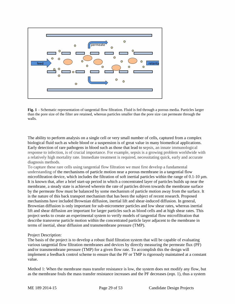
Tangential flow filtration (TFF) is a continuous size exclusion method for filtering and concentrating
particles in a solution. Filtration can often be significantly improved by using a TFF system as opposed to
a dead-end flow system. When using tangential flow techniques fouling can be mitigated by processing
fluid flows along the membrane surface rather than passing through the membrane structure. In TFF, the
feed is transported across the filter membrane (tangentially). A proportion of the material, which is
smaller than the membrane pore size, passes through the membrane as permeate. The fluid that is retained
on the feed side of the membrane is the retentate.
ME 189 2014-15 Page 29 of 53 Candidate Design Projects
Fig. 1 – Schematic representation of tangential flow filtration. Fluid is fed through a porous media. Particles larger
than the pore size of the filter are retained, whereas particles smaller than the pore size can permeate through the
walls.
The ability to perform analysis on a single cell or very small number of cells, captured from a complex
biological fluid such as whole blood or a suspension is of great value in many biomedical applications.
Early detection of rare pathogens in blood such as those that lead to sepsis, an innate immunological
response to infection, is of crucial importance. For example, sepsis is a growing problem worldwide with
a relatively high mortality rate. Immediate treatment is required, necessitating quick, early and accurate
diagnosis methods.
To capture these rare cells using tangential flow filtration we must first develop a fundamental
understanding of the mechanisms of particle motion near a porous membrane in a tangential flow
microfiltration device, which includes the filtration of soft inertial particles within the range of 0.1-10 µm.
It is known that, after a brief start-up period in which a concentrated layer of particles builds up near the
membrane, a steady state is achieved wherein the rate of particles driven towards the membrane surface
by the permeate flow must be balanced by some mechanism of particle motion away from the surface. It
is the nature of this back transport mechanism that has been the subject of recent research. Proposed
mechanisms have included Brownian diffusion, inertial lift and shear-induced diffusion. In general,
Brownian diffusion is only important for sub-micrometer particles and low shear rates, whereas inertial
lift and shear diffusion are important for larger particles such as blood cells and at high shear rates. This
project seeks to create an experimental system to verify models of tangential flow microfiltration that
describe transverse particle motion within the concentrated particle layer adjacent to the membrane in
terms of inertial, shear diffusion and transmembrane pressure (TMP).
Project Description:
The basis of the project is to develop a robust fluid filtration system that will be capable of evaluating
various tangential flow filtration membranes and devices by directly measuring the permeate flux (PF)
and/or transmembrane pressure (TMP) for a given flow rate. To accomplish this the design will
implement a feedback control scheme to ensure that the PF or TMP is rigorously maintained at a constant
value.
Method 1: When the membrane mass transfer resistance is low, the system does not modify any flow, but
as the membrane fouls the mass transfer resistance increases and the PF decreases (eqn. 1), thus a system
feed retentate
permeate
ME 189 2014-15 Page 30 of 53 Candidate Design Projects
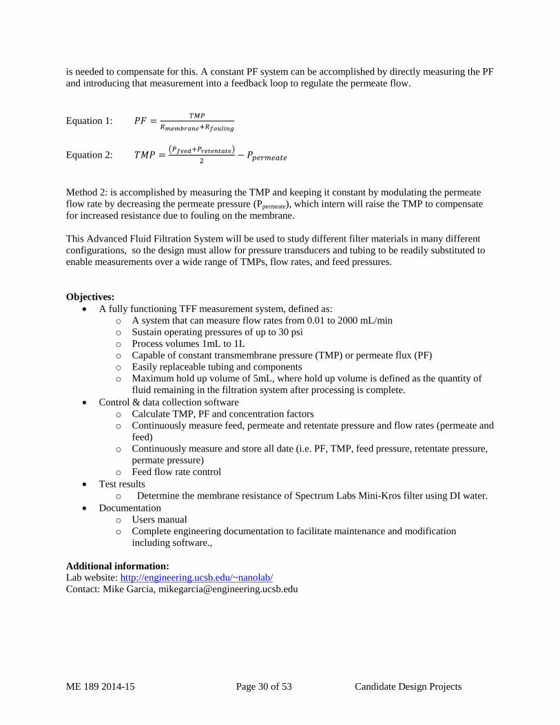
is needed to compensate for this. A constant PF system can be accomplished by directly measuring the PF
and introducing that measurement into a feedback loop to regulate the permeate flow.
Equation 1:
Equation 2: ( )
Method 2: is accomplished by measuring the TMP and keeping it constant by modulating the permeate
flow rate by decreasing the permeate pressure (Ppermeate), which intern will raise the TMP to compensate
for increased resistance due to fouling on the membrane.
This Advanced Fluid Filtration System will be used to study different filter materials in many different
configurations, so the design must allow for pressure transducers and tubing to be readily substituted to
enable measurements over a wide range of TMPs, flow rates, and feed pressures.
Objectives:
A fully functioning TFF measurement system, defined as:
o A system that can measure flow rates from 0.01 to 2000 mL/min
o Sustain operating pressures of up to 30 psi
o Process volumes 1mL to 1L
o Capable of constant transmembrane pressure (TMP) or permeate flux (PF)
o Easily replaceable tubing and components
o Maximum hold up volume of 5mL, where hold up volume is defined as the quantity of
fluid remaining in the filtration system after processing is complete.
Control & data collection software
o Calculate TMP, PF and concentration factors
o Continuously measure feed, permeate and retentate pressure and flow rates (permeate and
feed)
o Continuously measure and store all date (i.e. PF, TMP, feed pressure, retentate pressure,
permate pressure)
o Feed flow rate control
Test results
o Determine the membrane resistance of Spectrum Labs Mini-Kros filter using DI water.
Documentation
o Users manual
o Complete engineering documentation to facilitate maintenance and modification
including software.,
Additional information:
Lab website: http://engineering.ucsb.edu/~nanolab/
Contact: Mike Garcia, [email protected]
ME 189 2014-15 Page 31 of 53 Candidate Design Projects
Adaptive Molds for Precision Far IR Optics – Lubin
Project adviser: TBD
Questions: E-mail me-capstone.engineering.ucsb.edu
Customer contact information: TBD
Sponsor information: This project will be under the direction of Prof. Philip Lubin of the Physics
department. His research interests are in studies of the early universe and in developing new and unique
instruments, detectors and telescopes for this purpose. His work includes ground based from the South
Pole and White Mountain, balloon borne (40 Km altitude), space based systems and recently planetary
defense. Many of his research interests can be found on his web page www.deepspace.ucsb.edu.
Background: Large telescopes for sub orbital and orbital use are made from lightweight segmented
elements rather than one large monolithic mirror. Typically each element is made into a mosaic structure
to form the full telescope. The JWST (James Webb Space Telescope) is an example of this. In order to
form very large mirrors (10+ meters in diameter) the individual elements need to be extremely
lightweight. For far infrared work this can be accomplished with carbon fiber reinforced plastic (CFRP)
panels with each panel made on a rigid mold of the negative of what is desired. The cost and difficulty of
making these molds is a large portion of the development cost of these systems. We propose a new type
of mold, namely one mold that is morphed into the proper shape via a software controlled series of
actuators with real time metrology feedback. In this way one mold can replace literally hundreds of
molds. A variant of the system can also be used to morph the individual panels into shape if they are
distorted from thermal or aging effects. Large telescopes in the Far IR (30-1000 microns wavelength) are
critical to understanding the origin of our universe.
Project Scope - In this project we are using a completely new approach by servoing a flexible mold made
of glass (or other materials) to form the proper surface shape. The shape is determined by a combination
of laser interferometry and optical photogrammetry. Once the mold is to a desired shape we will make
some samples of CFRP and fiberglass mirrors from them and measure their shapes and compare to the
desired shape. This program will use complex modeling and modern metrology methods.
Objectives:
The lab has currently designed and fabricated a 1/3 scale model that is capable of limited testing. This
model is capable of inducing a shape change for a circular glass test sample with servo controlled edge
displacements. Meterology efforts have been developed that are capable of measuring induced
deformation of the glass test sample. The desired end-item shape is an off-axis parabola.
Project objectives include
- develop a predictive analytical model of deformation with induced edge effects
- correlate the analytical model with obtained test results
- develop appropriate servo controls and edge fixturing capable of producing a off-axis parabolic
shape for a 1m scale design with focal length approximately 7 m
Additional information:

ME 189 2014-15 Page 32 of 53 Candidate Design Projects
Student Requirements – Passionate desire to excel. This is a challenging project of significant
importance to industry and future space programs as well as molds for commercial systems such as
surfboards and car parts.
Student Qualifications – Ideally a mix of students who understand and can apply complex FEA
modeling and who desire to delve into servoed mechanical system. Students will learn elements of laser
metrology and photogrammetry.
For more info: http://www.deepspace.ucsb.edu/people/prof/
ME 189 2014-15 Page 33 of 53 Candidate Design Projects
Microfluidic interface bonding tool – Microfluidics Lab
Project adviser: TBD
Questions: E-mail me-capstone.engineering.ucsb.edu
Customer contact information: TBD
Sponsor Information: The CNSI Microfluidics Lab is an open-access laboratory in Elings Hall for the
fabrication of microfluidic chips. The lab has a broad user base that includes engineers, chemists,
biologists and materials scientists.
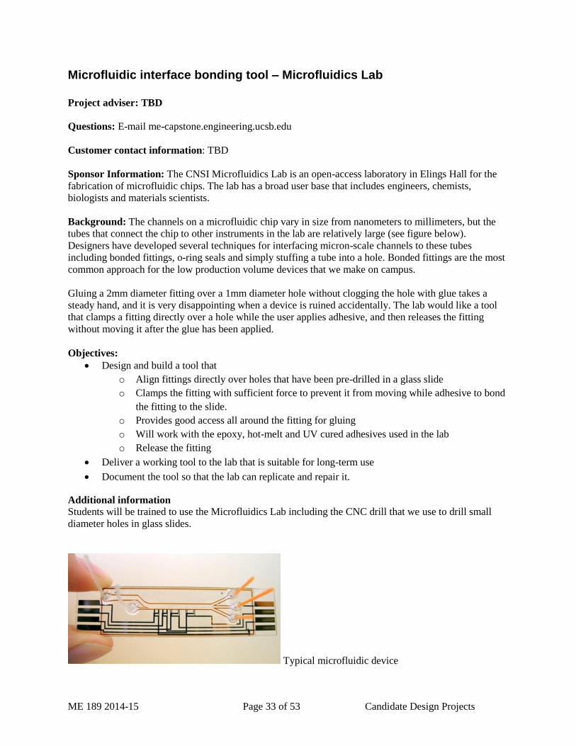
Background: The channels on a microfluidic chip vary in size from nanometers to millimeters, but the
tubes that connect the chip to other instruments in the lab are relatively large (see figure below).
Designers have developed several techniques for interfacing micron-scale channels to these tubes
including bonded fittings, o-ring seals and simply stuffing a tube into a hole. Bonded fittings are the most
common approach for the low production volume devices that we make on campus.
Gluing a 2mm diameter fitting over a 1mm diameter hole without clogging the hole with glue takes a
steady hand, and it is very disappointing when a device is ruined accidentally. The lab would like a tool
that clamps a fitting directly over a hole while the user applies adhesive, and then releases the fitting
without moving it after the glue has been applied.
Objectives:
Design and build a tool that
o Align fittings directly over holes that have been pre-drilled in a glass slide
o Clamps the fitting with sufficient force to prevent it from moving while adhesive to bond
the fitting to the slide.
o Provides good access all around the fitting for gluing
o Will work with the epoxy, hot-melt and UV cured adhesives used in the lab
o Release the fitting
Deliver a working tool to the lab that is suitable for long-term use
Document the tool so that the lab can replicate and repair it.
Additional information
Students will be trained to use the Microfluidics Lab including the CNC drill that we use to drill small
diameter holes in glass slides.
Typical microfluidic device
ME 189 2014-15 Page 34 of 53 Candidate Design Projects
Automated system for degassing and curing microfluidic devices – Microfluidics Lab
Project adviser: TBD
Questions: E-mail me-capstone.engineering.ucsb.edu
Customer contact information: TBD
Sponsor Information: The CNSI Microfluidics Lab is an open-access laboratory in Elings Hall for the
fabrication of microfluidic chips. The lab has a broad user base that includes engineers, chemists,
biologists and materials scientists.
Background: Many microfluidic devices are made by casting silicone rubber on an etched master wafer
that has an inverted version of the desired microchannels. The process is described clearly at:
http://www.nanofab.ualberta.ca/wp-content/uploads/2009/03/boxedpdms.pdf
An important part of the process is removing any trapped gas bubbles and vapor dissolved in the liquid
silicone rubber so that bubbles don’t develop in the channels, and then curing the resin for several hours
in a 60 – 100C oven for several hours. Currently users need to come to the lab multiple times over the
course of 5-8 hours:
To apply and release the vacuum (2 or 3 cycles) in a bell jar
To put the ,mold in the oven
To remove the mold from the oven
We would like Mechanical Engineering students to build a system that would automatically control the
vacuum pressure and temperature in a chamber so that researchers can get repeatable devices with fewer
trips to the lab.
Objectives:
Deliver a lab-ready bench top curing system that can cure up to eight 100mm diameter wafers
Programmable application and release of the vacuum for periods of 1-60 minutes
Programmable temperature (40 – 100C) for periods of 10 – 600 minutes.
Provide the lab with complete documentation for operation and maintenance of the tool
Additional information:
This project may be of particular interest to “tinkerers” and engineers interested in automation. You will
work with vacuum systems, laboratory plumbing, temperature controllers, and convection heaters.
Labview, or a commercial automation system may be useful as a master controller.
The team working on this project will complete the lab orientation training in the CNSI Microfluidics Lab
and will be trained on all of the tools needed to cast microfluidic devices.
ME 189 2014-15 Page 35 of 53 Candidate Design Projects
Magnetic Tweezers with Oscillating Field Strength – Valentine
Project adviser: TBD
Questions: E-mail me-capstone.engineering.ucsb.edu
Customer contact information: TBD
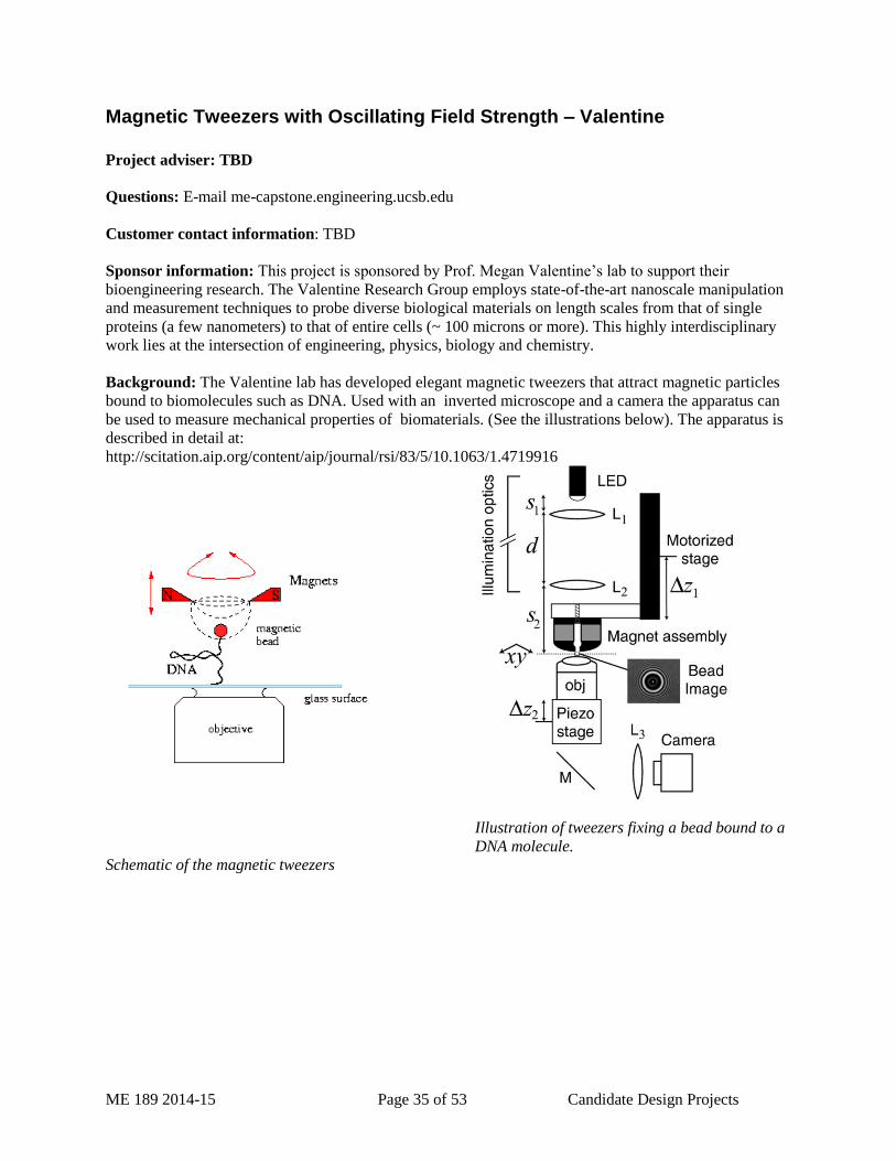
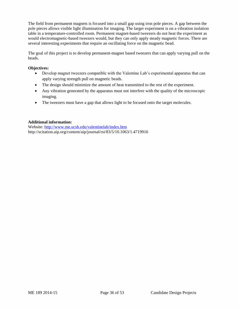
Sponsor information: This project is sponsored by Prof. Megan Valentine’s lab to support their
bioengineering research. The Valentine Research Group employs state-of-the-art nanoscale manipulation
and measurement techniques to probe diverse biological materials on length scales from that of single
proteins (a few nanometers) to that of entire cells (~ 100 microns or more). This highly interdisciplinary
work lies at the intersection of engineering, physics, biology and chemistry.
Background: The Valentine lab has developed elegant magnetic tweezers that attract magnetic particles
bound to biomolecules such as DNA. Used with an inverted microscope and a camera the apparatus can
be used to measure mechanical properties of biomaterials. (See the illustrations below). The apparatus is
described in detail at:
http://scitation.aip.org/content/aip/journal/rsi/83/5/10.1063/1.4719916
Illustration of tweezers fixing a bead bound to a
DNA molecule.
Schematic of the magnetic tweezers
ME 189 2014-15 Page 36 of 53 Candidate Design Projects
The field from permanent magnets is focused into a small gap using iron pole pieces. A gap between the
pole pieces allows visible light illumination for imaging. The larger experiment is on a vibration isolation
table in a temperature-controlled room. Permanent magnet-based tweezers do not heat the experiment as
would electromagnetic-based tweezers would, but they can only apply steady magnetic forces. There are
several interesting experiments that require an oscillating force on the magnetic bead.
The goal of this project is to develop permanent-magnet based tweezers that can apply varying pull on the
beads.
Objectives:
Develop magnet tweezers compatible with the Valentine Lab’s experimental apparatus that can
apply varying strength pull on magnetic beads.
The design should minimize the amount of heat transmitted to the rest of the experiment.
Any vibration generated by the apparatus must not interfere with the quality of the microscopic
imaging.
The tweezers must have a gap that allows light to be focused onto the target molecules.
Additional information:
Website: http://www.me.ucsb.edu/valentinelab/index.htm
http://scitation.aip.org/content/aip/journal/rsi/83/5/10.1063/1.4719916
ME 189 2014-15 Page 37 of 53 Candidate Design Projects
Withdrawn - Vacuum deposition tool for microfluidic surface coatings – Microfluidics Lab
Project adviser: TBD
Questions: E-mail me-capstone.engineering.ucsb.edu
Customer contact information: TBD
Sponsor information: The CNSI Microfluidics Lab is an open-access laboratory in Elings Hall for the
fabrication of microfluidic chips. The lab has a broad user base that includes engineers, chemists,
biologists and materials scientists.
Background: Uniform deposition of silane on the surface of microfluidic devices is a critical step in their
fabrication. The silane coatings can be used to control surface tension, and prevent the adhesion of
silicone resin to etched molds. The entire process of casting microfluidic devices is described at:
http://www.nanofab.ualberta.ca/wp-content/uploads/2009/03/boxedpdms.pdf
Many of the silane compounds of interest create unhealthy by-products when exposed to water –
including the water vapor in air. In order to work with these chemicals the lab has developed a simple
system using a vacuum chamber plumbed with vacuum and inert gas. The standard operating procedure
for this process is described in this standard operating procedure (SOP):
http://microfluidics.cnsi.ucsb.edu/SOP%20silation%20r4.docx
While the existing system works, it is cumbersome to use, and requires great care to avoid serious
mistakes. The lab would like to engage a team of mechanical engineers to make a safer, easy-to-use
system. We are open to either a manual or automated systems.
Objectives:
Deliver a lab-ready silane coating system plumbed for Nitrogen and vacuum.
The chamber should hold up to four 100mm diameter wafers.
The system should be easy to operate by a typical lab user
The system must be completely safe to use.
The purging and curing cycle should follow that described in the current SOP
Additional information:
This project may be of particular interest to “tinkerers” and engineers interested in microfluidics You will
work with vacuum systems, laboratory plumbing, Labview, or a commercial automation system may be
useful as a master controller.
The team working on this project will complete the lab orientation training in the CNSI Microfluidics Lab
and will be trained on all of the tools needed to coat microfluidic devices. Training on the lab’s laser
cutter will be provided if necessary for part fabrication.
ME 189 2014-15 Page 38 of 53 Candidate Design Projects
Pollutant Removal using Magnetic Nano-particles - Keller
Project adviser: TBD
Questions: E-mail me-capstone.engineering.ucsb.edu
Customer contact information: TBD
Sponsor information: I
This project has been independently student created with assistance by Prof. Arturo Keller of the Bren
School of Environmental Science and Management.
Background: The Keller Lab is developing innovative techniques for removing contaminants from water
using magnetic nano-particles (see http://pubs.acs.org/doi/ipdf/10.1021/sc400047q) Particles are designed
with surfaces that adsorb pollutants. When the particles are captured in magnetic fields the pollutants are
captured along with them.
The goal of the project is to design and manufacture a bench-scale instrument that would mix particles
into contaminated water, and then capture the particles. The apparatus would work with already
developed nano-particles and would deploy, move, and collect the particles in contaminated water. The
particles are iron based and are therefore ferrimagnetic. This allows them to be manipulated easily by
magnetic fields. As these particles are deployed in water, they come in contact with pollutants and
effectively absorb them. In order to speed this process up, stirring the mixture is usually required;
however an efficient energy solution is desired by moving only the particles rather than the bulk mass of
the water. The end design should incorporate a way to deploy the particles, mix them using
electromagnets, and then to collect them..
The nano-particles themselves have already been designed and created and would be available to students
for testing purposes. The project itself is fundamentally environmentally friendly and hopes to advance
the research of small to potentially large scale water pollutant clean-up.
Objectives:
Develop a bench-top pollution cleaning machine that can process 1 liter batches of polluted
water.
Compare the effectiveness of magnetic mixing techniques with mixers that stir the water.
Design a “flow-through” device that takes polluted water and particles as inputs, and cleaner
water and magnetic particles as outputs.
Demonstrate the effectiveness of the design.
Document the design and results.
Additional information:
http://pubs.acs.org/doi/abs/10.1021/sc400047q
ME 189 2014-15 Page 39 of 53 Candidate Design Projects
Lens Design and Fabrication for THz Applications – Sherwin
Project adviser: TBD
Questions: E-mail me-capstone.engineering.ucsb.edu
Customer contact information: TBD
Sponsor information: UCSB is the home to the Institue for Terahertz Science and Technology (ITST) –
a world-class facility for generating coherent beams in the terahertz wavelengths which are extremely
useful for research in material science, biology and physics. The primary radiation source at the UCSB
Institue for Terahertz Science and Technology consists of two fully operational Free-Electron Lasers, the
MM-FEL and the FIR-FEL, covering the range of 2.5 mm to 63 µm (4 to 160 cm-1 or 120 GHz to 4.75
THz). A third FEL, which is under development and has recently lased for the first time, will extend this
to 30 µm. These FELs are connected to a users' laboratory by a vacuum optical transport system. Twelve
switchable output ports allow multiple experimental setups. This facility is unique in providing tunable,
coherent, kilowatt-level radiation for scientific research in the far-infrared portion of the spectrum. A 6
MV, recirculating-beam, electrostatic accelerator generates a high quality 2 Amp beam for these FELs
which are located in a three position beam switchyard. A separate 2 MV, CW, MM-wave FEL is also
under development.
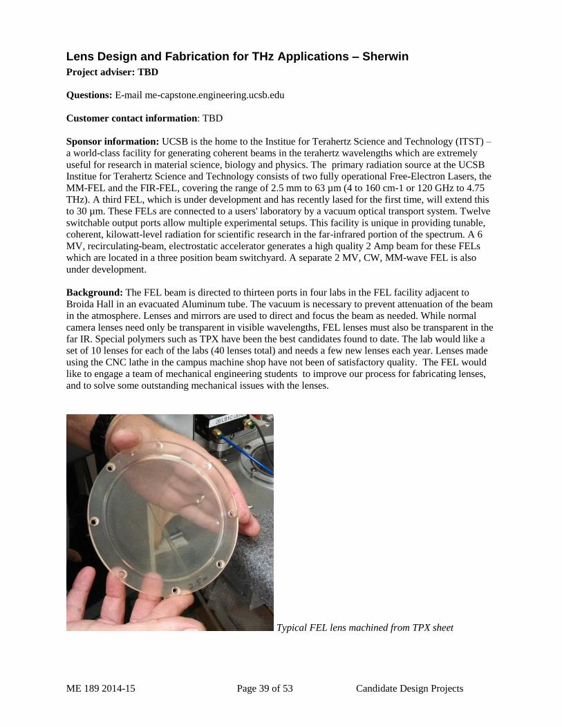
Background: The FEL beam is directed to thirteen ports in four labs in the FEL facility adjacent to
Broida Hall in an evacuated Aluminum tube. The vacuum is necessary to prevent attenuation of the beam
in the atmosphere. Lenses and mirrors are used to direct and focus the beam as needed. While normal
camera lenses need only be transparent in visible wavelengths, FEL lenses must also be transparent in the
far IR. Special polymers such as TPX have been the best candidates found to date. The lab would like a
set of 10 lenses for each of the labs (40 lenses total) and needs a few new lenses each year. Lenses made
using the CNC lathe in the campus machine shop have not been of satisfactory quality. The FEL would
like to engage a team of mechanical engineering students to improve our process for fabricating lenses,
and to solve some outstanding mechanical issues with the lenses.
Typical FEL lens machined from TPX sheet

ME 189 2014-15 Page 40 of 53 Candidate Design Projects
Objectives:
Analyze existing lenses
o Measure deviation of curvature from desired
o Evaluate mechanical deformation that leads to cracking with 1 Atm. pressure gradient
across the lens.
Evaluate alternatives for fabricating new lenses; including, but not limited to:
o Turning on CNC lathe
o Traditional grinding & polishing
o Turning on specialized lens lathes
Evaluate the optical properties of polymers suitable for the THz spectrum, recommend the best
polymer and grade for the lab’s research.
Recommend a process and material to the lab
Identify sources of material from which lenses can be fabricated.
Characterize lenses made using the recommended process.
Additional information:
http://www.itst.ucsb.edu/index.php
http://www.tydexoptics.com/products/thz_optics/thz_materials/

ME 189 2014-15 Page 41 of 53 Candidate Design Projects
3-D Calibration for Advanced Strain Mapping System – Zok
Project adviser: TBD
Sponsor information: Prof. Frank Zok – UCSB Materials Dept.
Questions: E-mail me-capstone.engineering.ucsb.edu
Customer contact information: TBD
Background: Advisor: Kirk Fields Support: Zok / Fields
Digital image correlation (DIC) is a mechanical strain-mapping technique utilizing high-resolution stereo
cameras to image a component and provide full, 3D displacements. The system requires the component
to be “speckled” with a black and white irregular pattern which is then tracked by hardware and software.
The digital image correlation technique is massively useful for visualizing deformations and strains on
full-size structures down to millimeter-scale components.
The 3D digital image correlation system requires accurate calibration to achieve quality data. The system
utilizes a precision target grid of known geometry which is imaged and compared to a look-up table. This
allows the software to compute all the imaging parameters (lens angles, focal lengths, working distance,
etc.). Positioning of the calibration target is paramount to good results.
This project will require designing and constructing a device which will allow for mounting of the
calibration target and provide manual, controlled motion of the target in six degrees-of-freedom (three
translations and three rotations). An additional engineering challenge is the requirement that the center of
the target not translate during rotation. The mount should be capable of supporting five sizes of targets as
well as provide line-of-sight 360-degrees around the target. The benchmark is a simple ball-and-socket
pivot with a slide.
Objectives: In progress
Additional information:
ME 189 2014-15 Page 42 of 53 Candidate Design Projects
Other Projects
Human Powered Concrete Mixer – African Sky and EWB
Project adviser: TBD
Questions: E-mail me-capstone.engineering.ucsb.edu
Customer contact information: TBD
Sponsor information: This project is sponsored by UCSB - Engineers Without Borders (EWB) and
African Sky – a non-governmental organization working in Mali, West Africa. Mali is a country filled
with industrious, innovative, and generous individuals who work against extreme poverty and hunger as
farmers, scientists, social activists, and policy makers. In service and deference to these individuals,
African Sky manages four project programs: education, community health, food security, and community
arts. Our project philosophy is based on the belief that humanity's physical, ecological, and spiritual well-
being is rooted in universal compassion and sustainable living.
Background:
One of African Sky’s key projects is a school building program in Mali. They have brought innovative
compressed earth block construction technology to Mali in order to reduce the cost of the school
buildings, and to make them more environmentally sustainable. Please see
http://www.africansky.org/projects/10schools.html for a detailed description of their program. Their most
recently completed school is shown below.
The floor and bond beam (a continuous reinforced concrete beam that ties the top of the walls together)
are made from concrete which they make by mixing cement, water, gravel and sand on the ground. A
cement mixer would both speed construction and enable greater consistency from batch to batch.
Traditional mixers aren’t practical because access to electricity and fuel is very limited, so they would
like us to help them by designing a human-powered mixer that could be fabricated for African Sky in
Malian machine shops. Our job would be to design and build a prototype, and deliver drawings and
instructions to the Malian machinists. The design must take into account the materials that are readily
available in Mali.

ME 189 2014-15 Page 43 of 53 Candidate Design Projects
Here is a list of key features that the African Sky team would like. We have suggested that the scope of
what they envision might require several machines, only one of which would be the focus year’s ME189
project.
We'd use the machine to mix batches of cement (used to make foundation blocks, plastering
walls, interior floors, and installing the roof and doors.
We'll also use the machine to mix batches of earth and cement to make our blocks with our block
press.
Cement batch = 1 50kg bag at a time. The cement they mix is standard cement with some water,
sand, and small stones. The team measures each batch as follows: [1-50kg sack of cement] + [2
"wheelbarrows" of stones/pebbles] + [1 "wheelbarrow" of sand] + [15 liters of water]. I believe
that will be a rather standard combination, but if you need me to measure the volume of our
wheelbarrow, I can do that... just let me know.
Brick mix batch = The big picture is that this recipe changes with each location, but not very
much. Ultimately, depending on the composition of the soil/earth we are using at any given site,
we will make a batch that is anywhere from 5-9% cement (the rest is earth). When that
combination is set for a given site, we use that site's custom earth/cement ratio to make a batch
for brick production. Once the earth/cement is mixed thoroughly, the team gradually adds water
to make it appropriate for brick making. We gauge the water content by grabbing a handful of
the mixture (with water mixed in)... then we make a ball... then we drop the ball from waist-
height onto the ground. If the ball breaks into a few pieces, we have our optimal mix. If the ball
breaks apart (completely or in more than a few pieces), we need to add water. If the ball remains
intact after falling, we added too much water and must add more of the earth/cement mix. The
team makes a batch of brick-making material using a sack of cement, and adds earth then water to
make the final mix. Block making mixture: [1-50kg sack of cement] + [5 wheelbarrows of
earth] + [2 wheelbarrows of sand] + [water, as indicated above]. Please note, that the team
assesses local soil to find the best available materials for our purposes. Then we adjust this basic
recipe depending on the soil composition; If there is too much sand already present in the soil
composition, the team follows this recipe = [1-50kg sack of cement] + [7 wheelbarrows of earth]
+ [water, as indicated above]. In the two sites we've produced mass quantities of blocks, the soil
composition varied and required slight modifications from the above. All this said, the basics
are: earth + 5-9% cement + enough water to pass the "drop test" described above. Last, once we
press a block, we use a penetrometer to test if we have the ideal soil structure. We press the
penetrometer into the fresh pressed block. If it makes an impression that is less than 5mm deep,
success! Anything deeper indicates a block mix that is substandard. The team tests every block...
even though that is a bit redundant (once a batch is a good batch, all resulting blocks should be
fine). When we have the recipe at its best (which is most of the time), the pentrometer
impression is about 2mm deep... well under the limit! The penetrometer, by the way, is
permanently set for 5kg/cm2.
In addition to mixing cement and the block-making mix, the team has a second "wish" for the
proposed machine. The want it to deliver the cement (upward too) so they can pour the grade
beam and bond beam. A hydraulic mixer does that as a standard operation, but the team is
completely open to the idea of creating two machines: one for mixing and another one for
delivering the cement... especially upward for that bond beam! Now we're using buckets and
pulleys. To find a way to get that cement (not the brick mix) up to the grade beam, that would
GREATLY increase our efficiency, reduce labor, and reduce costs (labor and waste).
The only other item the group mentioned as something that could help would be an improved
scaffolding system that could go from site to site. I need to do more research on this front. For
now I believe our strongest need is the mixer (along with the ability to pour the beams).
Power. Big issue here is that we are in non-electric sites. I would suggest thinking about a
machine (or machines) with alternative power sources: both manual (pedal power?) and diesel.
The diesel component could be something generic that could get energy from something separate
from the mixer/pourer itself... perhaps hooking up a moped or some other powered engine?
ME 189 2014-15 Page 44 of 53 Candidate Design Projects
Personally, I'm all for the manual/foot power, but I'm not the one that sweats in the sun while
making these blocks.
Last: block making is the TOUGHEST (labor-wise) component of our building technique. Our
partners and team frequently joke with me about how much effort is needed to produce the 6-
10,000 blocks required to build our structures. I imagine that if I was required to work on each
block making team, I'd be screaming for some powered assistance. To give you an idea, our
basic block dimensions, in mm: 290x140x90. See diagram below of the mould. Our press makes
ONE of these blocks at a time... and we make 1000s of them at each site!
Objectives:
Talk with African Sky and research concrete mixing so that the team understands the
requirements of the school construction team.
Research the limits of human-power as a driving force (speed, torque, typical power output,
preferred methods for capturing this power)
Talk with EWB members and African Sky to learn about the materials that are available in Mali,
and the capabilities of the machine shops there.
Develop practical design alternatives – (this will include building prototypes, sketching, testing
and analysis) – that are:
o Practical
o Durable
o Very inexpensive
o Easily reparable
o Buildable in Mali
Establish a rational method for selecting the most promising design alternative.
Complete the design and analysis of that option.
Build, test, revise.
Communicate the design in a form that is usable by the Malian shops
Additional information:
African Sky website: http://www.africansky.org/
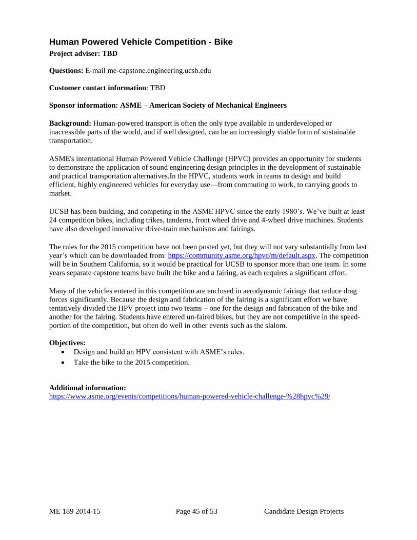
ME 189 2014-15 Page 45 of 53 Candidate Design Projects
Human Powered Vehicle Competition - Bike
Project adviser: TBD
Questions: E-mail me-capstone.engineering.ucsb.edu
Customer contact information: TBD
Sponsor information: ASME – American Society of Mechanical Engineers
Background: Human-powered transport is often the only type available in underdeveloped or
inaccessible parts of the world, and if well designed, can be an increasingly viable form of sustainable
transportation.
ASME's international Human Powered Vehicle Challenge (HPVC) provides an opportunity for students
to demonstrate the application of sound engineering design principles in the development of sustainable
and practical transportation alternatives.In the HPVC, students work in teams to design and build
efficient, highly engineered vehicles for everyday use—from commuting to work, to carrying goods to
market.
UCSB has been building, and competing in the ASME HPVC since the early 1980’s. We’ve built at least
24 competition bikes, including trikes, tandems, front wheel drive and 4-wheel drive machines. Students
have also developed innovative drive-train mechanisms and fairings.
The rules for the 2015 competition have not been posted yet, but they will not vary substantially from last
year’s which can be downloaded from: https://community.asme.org/hpvc/m/default.aspx. The competition
will be in Southern California, so it would be practical for UCSB to sponsor more than one team. In some
years separate capstone teams have built the bike and a fairing, as each requires a significant effort.
Many of the vehicles entered in this competition are enclosed in aerodynamic fairings that reduce drag
forces significantly. Because the design and fabrication of the fairing is a significant effort we have
tentatively divided the HPV project into two teams – one for the design and fabrication of the bike and
another for the fairing. Students have entered un-faired bikes, but they are not competitive in the speed-
portion of the competition, but often do well in other events such as the slalom.
Objectives:
Design and build an HPV consistent with ASME’s rules.
Take the bike to the 2015 competition.
Additional information:
https://www.asme.org/events/competitions/human-powered-vehicle-challenge-%28hpvc%29/
ME 189 2014-15 Page 46 of 53 Candidate Design Projects
Withdrawn - Human Powered Vehicle Competition - Fairing
Project adviser: TBD
Questions: E-mail me-capstone.engineering.ucsb.edu
Customer contact information: TBD
Sponsor information: ASME – American Society of Mechanical Engineers
Background: Human-powered transport is often the only type available in underdeveloped or
inaccessible parts of the world, and if well designed, can be an increasingly viable form of sustainable
transportation.
ASME's international Human Powered Vehicle Challenge (HPVC) provides an opportunity for students
to demonstrate the application of sound engineering design principles in the development of sustainable
and practical transportation alternatives.In the HPVC, students work in teams to design and build
efficient, highly engineered vehicles for everyday use—from commuting to work, to carrying goods to
market.
UCSB has been building, and competing in the ASME HPVC since the early 1980’s. We’ve built at least
24 competition bikes, including trikes, tandems, front wheel drive and 4-wheel drive machines. Students
have also developed innovative drive-train mechanisms and fairings.
The rules for the 2015 competition have not been posted yet, but they will not vary substantially from last
year’s which can be downloaded from: https://community.asme.org/hpvc/m/default.aspx. The competition
will be in Southern California, so it would be practical for UCSB to sponsor more than one team.
Many of the vehicles entered in this competition are enclosed in aerodynamic fairings that reduce drag
forces significantly. Because the design and fabrication of the fairing is a significant effort we have
tentatively divided the HPV project into two teams – one for the design and fabrication of the bike and
another for the fairing. Students have entered un-faired bikes, but they are not competitive in the speed-
portion of the competition, but often do well in other events such as the slalom.
Objectives:
Design and build an aerodynamic fairing for UCSB’s bike that is consistent with ASME’s rules.
Participate in the 2015 competition.
Additional information:
https://www.asme.org/events/competitions/human-powered-vehicle-challenge-%28hpvc%29/
ME 189 2014-15 Page 47 of 53 Candidate Design Projects
Soft Robotics for Materials Science Education
Project adviser: TBD
Questions: E-mail me-capstone.engineering.ucsb.edu
Customer contact information: TBD
Sponsor information: This project will be under the direction of Frank Kinnaman of MRL Education
Outreach.
Background:
Purpose
The primary desired outcome for this project is a range of soft robots to demonstrate to k-12 students
during the MRL’s “Bio-Inspired Materials” outreach activity. In this activity students construct their own
primitive claw using materials such as rubber tubing, drinking straws, paperclips and string. The
demonstration pieces generated by this project would be part of a presentation to engage the students and
generate discussion into a fascinating and young area of research. Response to our efforts thus far has
been encouraging, with its inherently tactile nature soft robotics is an opportunity to engage the public in
materials science that they can touch and feel. We foresee imaginative outcomes to this project but
further progress and refinement of methods is needed.
Project Description
“Soft robotics” is an emerging field with possible future medical and industrial applications. This project
is an exploration of techniques to create various soft robotics prototypes including “gripper”, “crawler”
and possibly “tentacle” and “glove” models. The molds for these robots are made using desktop
fabrication tools (3d printing) and use materials that are relatively inexpensive when compared with
traditional robotics A capstone team would continue and accelerate our initial efforts, initially exploring
the benefits of a novel “seamless” method using a lost wax technique and then applying any method
development advances into whatever device fabrication that project time allows. The basic workflow of
soft robotic fabrication includes CAD design, 3d printing of the molds, wax and silicone rubber casting
and also control systems. Small changes to each design can result in dramatic performance differences;
we see this project as an iterative process. Good documentation of successful device fabrication is
important to this project. The team will be required to apply for a URCA grant to defray the cost of
consumable materials for the project.
Background
Biological systems integrate materials in unprecedented ways - for example researchers at UCSB have
found that the Humboldt squid has a beak that is exceptionally hard yet still manipulated easily by its soft
body (the mechanical analogy is a razor blade in jello). The field of robotics is currently moving beyond
conventional rigid pieces to the use of soft materials, such as polymers and gels, to mimic such designs in
living systems. Importantly, the materials and tools that are used to make soft robotics are readily
available, making soft robotics significant more accessible and inexpensive than conventional robotics.
Inspired by the work of the Whitesides group at Harvard University we have implemented a pilot project
to test the suitability of Soft Robotics for K-12 education. Teachers and student reception of our
preliminary efforts in soft robotics has been good. In January 2013 some initial prototypes were
presented to a group of teachers in the MRL’s “Models and Materials” project. Their written feedback
demonstrates the synergy between science and engineering:
“Soft robotics can be used to integrate engineering and biology”
“Soft materials provide solutions to engineering challenges”
“Soft robotics—demos were very applicable to life science”
“Interesting to hear the difficulties and limitations with these two specific materials”
“Engineering is so much more than force diagrams”
“Importance of research and trial and error experiment”

ME 189 2014-15 Page 48 of 53 Candidate Design Projects
“Soft robotics—great application to body systems”
Important for this outreach project are accessible methods, so that once a working model is achieved
others with limited budgets and resources can replicate the project. Our reliance on 3d printing we feel is
reasonable due to the recent explosion in budget 3d printers and printing services.
Four classes of robot are targeted as possible projects. In the order of proposed exploration and in order
of complexity they are crawler, gripper, tentacle, and glove. Most of our work up until now has been
focused on the first two robots and the methods for all of these efforts can be separated into two distinct
segments: “slab” and “seamless”. The initial slab explorations closely followed the methods of the
pioneers in the field (Whitesides: http://gmwgroup.harvard.edu/research/index.php?page=23) but were
mostly abandoned due to serious problems in replicating the good results in the “slab” type of method
they employed. Although the mold fabrication is straightforward for this method most of the models
failed along the glued seam of the layers of the robot. The current seamless method of exploration (partly
inspired by other independent work such as http://superreleaser.com/research/)
removes this interface by casting the devices as a single piece and melting out a suspended wax insert (the
wax melts at approx. 50C, a temperature the silicone rubber can withstand). New challenges are certainly
encountered in this method but initial results are that it is overall a superior approach. With some
research into both methods we propose this as the area the capstone team will at least initially explore.
Other parameters include the shape of the internal channels, wall thickness and the amount of branching
of each channel (branching creates internal walls which generate more force for movement). Whatever
the technique, a product of this project will be a set of guidelines for design – these guidelines could be
applied to designing any of the particular “species” of robot.
We are confident that with proper attention, the team will be able to deliver functional pneumatically
powered soft robots with simple repeatable and reliable manufacturing methods. Our primitive steps
towards these goals have demonstrated proof of concept but have been hindered by engineering hurdles
that a capstone team should overcome. Please contact Frank Kinnaman ([email protected]) with
any questions.
Objectives:
Models must remain intact for long-term use ( > 5000 cycles)
Explore actuators made from multiple polymers
crawler
Develop an understanding of soft robotics so that you can predicts the performance of soft robot
actuators (force, displacement and frequency response) for a given design (considering the
geometry, material properties and actuation pressure).
Explore options for fabricating small scale (5-20cm) robots that may include 3D printing, casting,
and molding different polymers.
Develop a set of soft robots for outreach-related demonstrations and experiments by K-12
students capable of surviving > 5,000 cycles.
With MRL’s guidance make simple videos that demonstrate the basic principles of soft robotic
actuators.
Additional information:
http://softroboticstoolkit.com/home
A thread reinforced crawler:
https://www.youtube.com/watch?v=0t2The3I9wI
A gripper robot:
https://www.youtube.com/watch?v=EzrkwkCLuiA
an early crawler
https://www.youtube.com/watch?v=CixoM70dxlw
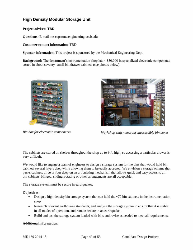
ME 189 2014-15 Page 49 of 53 Candidate Design Projects
High Density Modular Storage Unit
Project adviser: TBD
Questions: E-mail me-capstone.engineering.ucsb.edu
Customer contact information: TBD
Sponsor information: This project is sponsored by the Mechanical Engineering Dept.
Background: The department’s instrumentation shop has ~ $50,000 in specialized electronic components
sorted in about seventy small bin drawer cabinets (see photos below).
Bin box for electronic components
Workshop with numerous inaccessible bin boxes
The cabinets are stored on shelves throughout the shop up to 9 ft. high, so accessing a particular drawer is
very difficult.
We would like to engage a team of engineers to design a storage system for the bins that would hold bin
cabinets several layers deep while allowing them to be easily accessed. We envision a storage scheme that
packs cabinets three or four deep on an articulating mechanism that allows quick and easy access to all
bin cabinets. Hinged, sliding, rotating or other arrangements are all acceptable.
The storage system must be secure in earthquakes.
Objectives:
Design a high-density bin storage system that can hold the ~70 bin cabinets in the instrumentation
shop.
Research relevant earthquake standards, and analyze the storage system to ensure that it is stable
in all modes of operation, and remain secure in an earthquake.
Build and test the storage system loaded with bins and revise as needed to meet all requirements.
Additional information:
ME 189 2014-15 Page 50 of 53 Candidate Design Projects
(NEW!) Satellite Latching Mechanism – Northrop-Grumman
Project adviser: TBD
Questions: E-mail me-capstone.engineering.ucsb.edu
Customer contact information: TBD
Sponsor information: This project is in cooperation and partnership under a gift with Northrop
Grumman Corporation (NGC) located in Redondo Beach, California. NGC Project Lead – Phil Barnes.
Northrup Grumman Project Name: Passive “bleed and blow” airfoil wind tunnel test
NGC is a $30 billion global defense and technology company whose 120,000 employees provide
innovative systems, products, and solutions in information and services, electronics, aerospace and
shipbuilding to government and commercial customers worldwide.
NGC is a premier developer, integrator, producer and supporter of manned and unmanned aircraft,
spacecraft, high-energy laser systems, microelectronics and other systems and subsystems critical to
maintaining the nation’s security and leadership in science and technology. These systems are used,
primarily by government customers, in many different mission areas including intelligence, surveillance
and reconnaissance; communications; battle management; strike operations; electronic warfare; missile
defense; earth observation; space science; and space exploration.
NGC develops a broad range of systems at the leading edge of space, defense and electronics technology.
Building on a heritage of innovation, we create sophisticated products that contribute significantly to the
nation's security and leadership in science and technology.
Background:
Aerospace Applicability: Mechanisms and deployables are an important aspect of any spacecraft design
due to the likely loss of the mission if a failure of the mechanism occurs. Students will design, build, and
test a latching mechanism that will to join two CubeSats together to form one larger satellite. The
resulting design must concurrently meet stringent load requirements, controlled mating parameters, and
strict latched characteristics to ensure mission success. Typical driving parameters include thermal
environments, on-orbit loads, relative velocities of the mating satellites, size, mass, latch stiffness, and
reliability. Verification of the design will also require students to develop test fixtures and/or feature
simulator(s) that represent the baseline design or enable testing in earth’s gravitational environment.
Specific Project Details: CubeSats are small “nano-satellites” that are used to perform space science and
exploration missions. The standard 10x10x10 cm basic CubeSat is referred to as “1U” CubeSat and can
be combined to create larger CubeSats (2U, 3U…). CubeSats are typically launched and deployed from a
mechanism called a Poly-PicoSatellite Orbital Deployer (P-POD) which has the capacity for a 3U
CubeSat. The 2014-2015 team will design and test aspects of a latching mechanism that will join two
deployed 3U CubeSats together to form one 6U satellite. The team will be given typical launch and on-
orbit environments, and well as physical constraints and latch stiffness requirements.
Support: Northrop Grumman will provide the detailed initial requirements to the team within the first
week of instruction and support early clarification meetings. A Northrop representative will be available
via email and telecons throughout the year to answer technical questions or provide guidance where
necessary (but not do your work!). Northrop will also attend all course design reviews to support the
ME 189 2014-15 Page 51 of 53 Candidate Design Projects
team. Typically, Northrop Grumman is able to support some manufacturing of student hardware. This
support is not guaranteed however and students should plan for completing all tasks and manufacturing
all prototypes on their own. Schedule permitting, student team members are typically invited to the
Northrop Grumman Facility in the 2nd semester for an informal tour. All students are eligible to
participate on the Northrop Grumman sponsored team; however, non-citizens cannot visit our facility due
to government regulations.
Objectives:
Perform design trade studies
Complete a detailed design package to meet the specified requirements/constraints.
Prototype development and testing will be conducted to validate select features of the proposed
design (examples: verify latch stiffness predictions, deployment function, reliability, etc).
Additional information:
The company requires US citizenship for all site visits and a Confidential Disclosure Agreement.
Students with an interest in mechanisms and mechanical systems and an interest in the aerospace industry
will find this project demanding and technically challenging.
This project may require travel to company facility and may require periodic teleconferences.
Website: www.northropgrumman.com/index.html
ME 189 2014-15 Page 52 of 53 Candidate Design Projects
(NEW!) Autonomous Oceanographic Research Vessel – Washburn Lab
Project adviser: TBD
Questions: E-mail me-capstone.engineering.ucsb.edu
Customer contact information: TBD
Background: The Washburn Lab in the Marine Science Insitute has been conducting reaserch into the use
of autonomous vehicles in the field of oceanographic research. The first vehicle designed and built by the
lab consisted of a fixed wing aircraft with a 9ft wingspan, which carried a compact radar transmitter on
board. The aircraft was hand launched and proceeded to fly a perfect arc over the ocean (accurate up to
5m) over a total distance of 20km around a coastal CODAR surface current monitoring antenna station
for antenna pattern calibration purposes. The use of this aircraft dramatically reduced the cost, time
required, and manpower necessary for conducting antenna patterns at the Univeristy's numerous CODAR
stations along the Central Coast. This concept is now being adapted by other reaserch institutions as an
alternative to surface vessel based calibration. Follwing the success of this project, development began on
an autonomous quadcopter which would carry a custom developed lightweight sample bottle for
collecting seawater samples. The quadcopter would fly out approximately 500m-2000m into the Santa
Barbara Channel, dip its collection bottle, which triggers to collect a sample of the water colunm at a
specified depth, and return to its launch point with the sample. Flight testing is currently underway for
this project and is proving very promising.
Statement of Problem: Autonomous vehicles provide incredible opportunities for advancement in many
fields of scientific research. The purpose of this project would be to develop a fully autonomous sub-
surface based vessel which would be capable of carrying and ADCP (Acoustic Doppler Current Profiler)
and other oceanographic equipment across the Santa Barbara Channel in order to obtain ocean current,
temperature, pH, etc, data across the width of the Channel in a short period of time. An efficient, stable,
and robust hull must be designed and contructed, as well as a power system capable of provided the
required speed and duration against potential strong currents and swells. The hull should be designed to
ride just beneath the surface (top deck awash) in order to minimize negative effects of strong winds. The
vessel must be entirely watertight and self sufficent. A cargo bay will be necessary for various
interchangeable oceanographic instruments. A cooling system for the electronics and drive will be
necessary to reduce the possiblility of drive failure due to overheating. A waterproof antenna and housing
wil be required to ensure the vessel can maintain a GPS fix and signal connection with it's base station.
Other obstacles and design requirements will be determined and dealt with as they arise (See images
below for a rough conceptual sketch).
Objectives:
Assess requirements for the vessel
o Size
o Propulsion
o Energy requirements / storage
o Payload
o Stability
o Ship / shore handling
o Legal / regulatory
Develop alternative design solutions
Decide on scale for prototype
Design, build and test prototype vessel
Revise as needed
Document design
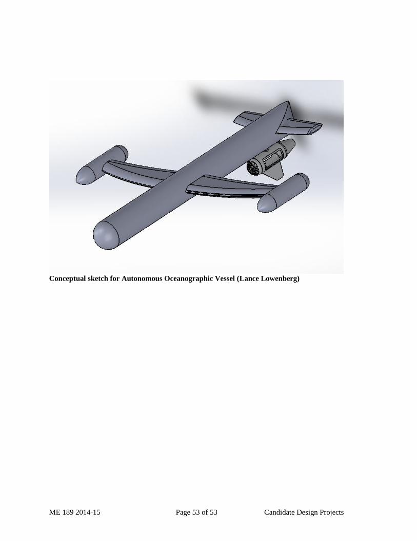
ME 189 2014-15 Page 53 of 53 Candidate Design Projects
Conceptual sketch for Autonomous Oceanographic Vessel (Lance Lowenberg)