mechanical drawing for beginners, giving the fundamental
TRANSCRIPT

THE UNIVERSITY
OF ILLINOIS
LIBRARY
14-4 ~B I 5"-m
JD*U« Due

MECHANICAL DRAWING for BEGINNERS
Giving the Fundamental Technic of
Modern Practice
By
CHARLES H. BAILEY Director of Manual Arts
Iowa State Teachers' College
THE MANUAL ARTS PRESS PEORIA, ILLINOIS
Copyright
Charles H. Bailey
1920

1\Q
ol?
H
IVt ^>\5irr>
U I PREFACE
THE fundamental principles involved in the making of working drawings are few and not difficult to comprehend. If properly
presented, they may be readily and quickly mastered by the learner, and, once mastered, furnish the basis upon which must be developed the ability to deal with special problems in drafting as they occur in the vari¬ ous applications of mechanical drawing in industrial and mechanical work. But these fundamental principles must be mastered; otherwise, the student will have difficulty later with the specialized work.
It is not only important to master principles but also to have an in¬ telligent understanding of and to form correct habits in the best pro¬ cedure and practice. A thoro understanding of principles is necessary to insure the correctness of a drawing, while correct procedure is essen¬ tial to the working out of a drawing effectively and economically.
It is the aim or this little book to present the fundamental principles of working drawings thru a series of progressive problems, and to pre¬ sent the fundamentals of procedure and practice by means of explana¬ tions, illustrative problems, and drawings given in connection with the problems. It is not intended to be a complete textbook of mechanical drawing but it gives the important things which the learner must master and upon which a more extensive study and training must be based.
The book is not intended to be used without a teacher. A person might get much from the book by working alone, but it is intended to be used in classes where the teacher gives full and careful instruction, both class and individual. It is to be used as an aid to the pupil and teacher rather than as a substitute for the teacher. To secure the best results, each pupil should have a book for constant reference.
The book is intended for use by beginners and should be equally val¬ uable to those who can take only a brief course and to those who expect to pursue more advanced study. It is not planned to cover any definite period of time. A class may be taken thru the course rather quickly, working only a limited number of problems in each section, thus getting all the principles, tho less thoroly; or a larger number of drawings may be made. The teacher may add others not given in the book, thus mak¬ ing a more complete course and giving the student greater power and dexterity.
The book does not lay claim to originality. Material has been gleaned from many sources. It is merely a re-statement of commonly
O
4*71190
4 MECHANICAL DRAWING FOR BEGINNERS
recognized principles and practice but in a somewhat different form. Instead of being divided into chapters presenting certain phases of the subject, the book (is arranged in sections dealing with certain types of problems and the information necessary to the solution of the problems given in connection with them. This seems to be the most direct and natural arrangement as it corresponds with the process of learning.
The author believes that the best way to learn to make working draw¬ ings is to make working drawings. Therefore, complete problems are used right from the start. Each drawing is entirely completed before passing to the next. Thus the pupil has a complete experience with each problem and the work has more meaning when presented in this way. No practice work is required and no purely copy work is per¬ mitted even when it involves a change of scale. The author’s experi¬ ence thru many years of teaching mechanical drawing to classes from the fifth grade to those in college convinces him that this is the best plan to follow.
The author wishes to make due acknowledgment to the various books and writings of others that have been a source >of information and in¬ spiration in making up this book, and to express his appreciation of the helpful suggestions that have been given by those persons to whom pre¬ liminary plans have been submitted.

CONTENTS Page
Preface. 3
Suggestions to the Teacher. 7
Instruments and Materials. 9
Section 1:
Laying Out Sheet for Practice Lettering; Also for Regular Draw¬ ing. Preliminary Explanations.11
Section 2:
Working Drawings of Objects Bounded by Plane Surfaces at Right Angles to Each Other. No Invisible Outlines. . . .21
Section 3:
Working Drawings of Objects Generally Rectangular in Form Having Some Invisible Outlines. Drawings, Full Size.37
Section 4:
Working Drawings of Objects Generally Rectangular in Shape Similar to Those in Preceding Sections, but Requiring to Be Drawn to Reduced Scale.43
Section 5:
Working Drawings of Objects Having Inclined Surfaces. That Is, Surfaces Other Than at Right Angles to Each Other. Draw¬ ings, Full Size or Reduced.47
Section 6:
Working Drawings of Straight Line Objects of Greater Complex¬ ity. Laying Out by Means of Center Lines.56
Section 7:
Working Drawings of Objects, Some Outlines of Which Are Circles or Arcs of Circles.62
Section 8:
Tracing and Blueprinting. Lettering, Titles, Etc.68

CONTENTS—Continued
Section 9: Page
Working Drawings of More Complex Objects Having Curved Out¬ lines. Projecting Points from Top View to End View, or from End View to Top View.72
* *
Section 10:
Working Drawings of One-Piece Objects Showing Full-Section or Half-Section Views.77
Section 11:
Working Drawings of Objects Consisting of More Than One Piece, Showing Full-Section or Half-Section Views.81
Section 12:
Working Drawings of Miscellaneous Objects Representing Partial Sections, Revolved Sections and Breaks.84
Section 13...
Index ..
88
91

SUGGESTIONS TO THE TEACHER
HEN using this book, it is suggested that teachers assign the ex¬ planatory matter for study outside of class periods just as
would be done with any textbook. The teacher should then go over the same carefully with the class, making clear the points brought out in the book and giving such other instruction as may seem desirable. While doing the work, the pupil should have the book before him and make constant reference to it.
Be sure that the students understand and actually practice the cor¬ rect methods of procedure. See that they understand the different stages and steps in making a drawing as given here and that they ob¬ serve them strictly when doing the work. This may perhaps seem rather formal at first, but, if insisted upon, correct habits will quickly be formed and difficulties of manipulation quickly overcome.
It will be well to make free use of class discussions, recitations and ex¬ aminations covering principles and practice as the work proceeds.
Notice that the plan of instruction involves the making of complete drawings from the beginning. This plan makes it necessary to proceed rather slovly at first as there are quite a number of things to be learned in order to make the first drawing. This can be done, however, without making the work tiresome, and, by so doing, the pupil obtains a clearer idea of the purpose of the work.
Emphas: e first of all a thoro understanding of principles and the ability to use drawing as a means of expression, or as a language. This is the most important thing for the student to acquire. In the second place, emphasize the use of correct methods of manipulation and pro¬ cedure, and in the third place, emphasize accuracy and neatness in the finished drawing. Accuracy and neatness iare largely the result of practice and should develop as the pupil has experience. Try to see that each drawing represents the pupil’s best effort and that each suc¬ ceeding one is better than the one before.
No extended treatment of lettering is undertaken here, not because lettering is unimportant, but the scope of the book does not permit. It will be sufficient in this course for the pupil to learn the vertical capitals as given in the book. Assign practice work in lettering constantly thruout the course. If the teacher wishes to go further with the subject of lettering write to the publishers of this book for helpful material on the subject.

8 MECHANICAL DRAWING FOR BEGINNERS
Freehand sketching, preliminary to the mechanical working out of the drawings, is not required in the course as outlined. This is left to the discretion of the teacher. It may often be desirable to ask the student to make a freehand sketch of a problem on cheap sketching paper before attempting to draw it on the regular drawing paper, especially if he seems not to understand it thoroly or if it is complicated.
It will be noticed that data for the problems is given in two different ways, as perspective sketches dimensioned or accompanied by notes, and as incomplete working drawings which the student is to complete. Each problem requires a solution and is a test of the pupil’s knowledge and his ability to use drawing. If he understands, his solution will be correct; if his solution is not correct he does not understand and needs more instruction over the points that are not clear.
The teacher will find it helpful to assign problems in drawing from ob¬ jects used as models. This is especially desirable for the first problems and it would be well if models of some of the objects used for problems in the book were made and used to make the work more clear. An ex¬ tensive collection of good models is very important. The teacher should also assign problems in addition to those given in the book. This may be done by using models, by placing problems upon the blackboard or using blueprints. Problems correlated with shop work may be used. Any set of problems may be used so long as they fit into the scheme of the book. Thus it has a wide range of adaption.
Tracing, inking upon the paper and blueprinting may be entirely omitted without breaking the continuity of the course. Thus pencil work only may be done if desired.
Give special attention to the proper placing of dimensions. Much de¬ pends upon this, and too often it is carelessly done. The manner in which dimensions are placed upon the perspective sketches should not be taken as suggestions for placing them upon the working drawing, as this is an entirely different problem. See that pupils follow the sugges¬ tions about dimensioning given in the text, and give all the additional help possible in this rather difficult matter.
Several problems are given under each section. These need not all be made by each pupil. Assign such as seem best under the circumstances so as to give the pupil as much experience and knowledge as is possible
in the time available. This little book, properly used, should be a real help to both pupil and
teacher, and better results should be secured than is often the case where
no such book is used.
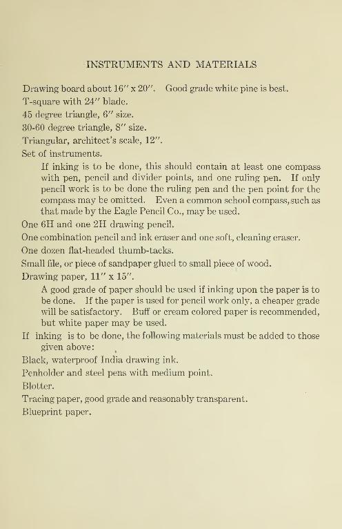
INSTRUMENTS AND MATERIALS
Drawing board about 16" x 20". Good grade white pine is best.
T-square with 24" blade.
45 degree triangle, 6" size.
30-60 degree triangle, 8" size.
Triangular, architect’s scale, 12".
Set of instruments.
If inking is to be done, this should contain at least one compass with pen, pencil and divider points, and one ruling pen. If only pencil work is to be done the ruling pen and the pen point for the compass may be omitted. Even a common school compass, such as that made by the Eagle Pencil Co., may be used.
One 6H and one 2H drawing pencil.
One combination pencil and ink eraser and one soft, cleaning eraser.
One dozen flat-headed thumb-tacks.
Small file, or piece of sandpaper glued to small piece of wood.
Drawing paper, 11" x 15".
A good grade of paper should be used if inking upon the paper is to be done. If the paper is used for pencil work only, a cheaper grade will be satisfactory. Buff or cream colored paper is recommended, but white paper may be used.
If inking is to be done, the following materials must be added to those given above:
Black, waterproof India drawing ink.
Penholder and steel pens with medium point.
Blotter.
Tracing paper, good grade and reasonably transparent.
Blueprint paper.


SECTION 1.
Laying Out Sheet for Practice Lettering; Also for Regular
Drawing. Preliminary Explanations.
1. Fastening paper to drawing board. Place the T-square so that the inside edge of the head rests snugly against the left-hand edge of the drawing board, as shown in Fig. 1.
©-
d>-~N
Drawinq paper.
MD
/—®
0 &
^ > 0 ®
© © c
1 1 1
T-square. / Drawma board /
Fig. 1
Place paper in position with its lower edge resting against the upper edge of the T-square, and so located that the paper will be a little above and to the left of the center of the board.
Hold paper and T-square in place by resting the left hand lightly up¬ on them.1
Insert thumb-tack (marked 1 in the illustration, Fig. 1) into the upper left-hand corner of the paper, having the point of the tack about 1/8" from the edges of the paper.
See that the lower edge of the paper exactly corresponds with the upper edge of the T-square blade; then insert tacks numbered 2, 3, 4, Fig. 1, in the order of the numbers, placing the points of tacks less than 1/4" from the edges of the paper. Press tack heads down close to the paper so they will hold more securely and interfere as little as possible with the instruments.
0) NotQ. The T-square is used against the left-hand end of the drawing board if the pencil is used in the right hand. If the pencil is used in the left-hand, the re¬ verse of this position is taken.

12 MECHANICAL DRAWING FOR BEGINNERS
2. Sharpening pencils. For shape of pencil points see Fig. 2.
A 2H and a 6H pencil are recommended for use in this course but some may prefer a 4H or 5H grade in place of the 6H.
The 2H pencil, which has medium hard lead, is sharpened with a round point such as is used in ordinary writing.
Fig. 2
The 6H pencil, which has very hard lead, may be sharpened with either a round or a flat point. The flat point is better for drawing lines along a straight edge, or ruler, as it will make a fine line and at the same time wear longer than a round point. The round point is better for freehand work, and for marking off distances from the scale. A good plan is to sharpen the hard pencil with a flat point on one end and a round point on the other, reversing the pencil as necessary for different
kinds of work.
Cut away the wood from the pencil point with a knife, leaving the lead full size. Shape the lead on a file, a piece of sandpaper or emery cloth. Move the pencil back and forth'on the sandpaper with a rocking motion to produce the oval-shaped point.
3. Use of scale in measuring. The triangular scale commonly used for mechanical drawing has six graduated surfaces, Fig. 3. One of these is marked off in inches divided into halves, quarters, eighths and sixteenths as is customary on the common rule. This is the one used for making ordinary, full-size measurements and is the only one that the pupil need be concerned with at first. The other scales will be explained
later as they are needed.

LAYING OUT SHEET 13
When measuring, place the scale on the paper so that its edge is paral¬ lel with the direction in which the measurement is to be made, usually along some line already drawn. Have the zero of the scale, or some other main graduation on the scale, exactly coincide with the point from which the measurement is to be made.
Place the pencil point at the proper division of the scale for the re¬ quired measurement, holding the pencil perpendicular to the edge of the scale and slanting slightly away from it, as shown in Fig. 3. Use the round point of the pencil.
Make a fine, light dot by rotating the pencil between the fingers, hav¬ ing it lightly in contact with the paper. Do not press on the pencil or it will indent the paper.
4. Use of T-square in drawing horizontal lines. Remember that a right-handed person uses the T-square head against the left-hand edge of the board and vice versa.
Place the T-square on the paper with the inside of the head against the left-hand end of the board. Fig. 4. With the left hand on the T- square head, slide it into position for drawing the required line. Slide the left hand lightly along the blade and rest it at about the center so as to hold the instrument in position.
Place the pencil point in position against the upper edge of the T- square, holding the pencil so that its top slants toward the right and also slants slightly away from the edge, or toward the top of the board, thus bringing the pencil point into close contact with the T-square edge.
Draw the line with a motion from left to right. Do not push the pen¬ cil, point first, along the ruling edge.

14 MECHANICAL DRAWING FOR BEGINNERS
The full and dotted lines in the figure show two positions of the T- square, giving horizontal lines parallel to each other. Any other posi¬ tion of the T-square with its head against the same edge of the board will give lines parallel to these lines and to each other. Thus the T- square gives the direction of the line, and only one point is needed to lo¬ cate such a line.
0 O
■ i j
© 0] e i
0 © ; |
i _ ii i T-square i i i -^- i i
0 0
Drawino oaoer / -^-p-p-/
Drawing board
Fig. 4
A *
r
0
— \ v \ c
\ 0
0
>
® 0
© 1 0 ®i
1 i
i i i
i T-square ! I
I
0_O
Drqwing paper /
Drawing board /
Fig. 5
5. Use of triangle, with T-square, in drawing vertical lines. Place the T-square on the drawing board with the head bearing firmly against the left-hand end of the board, as for drawing horizontal lines.

LAYING OUT SHEET 15
Place the triangle with one of its edges against the upper edge of the T- square, as shown in Fig. 5.
Hold the T-square in place by resting the left hand lightly upon the blade. By using the fingers of the left hand, slide the triangle into the exact position for drawing the required line, and hold it steady with the fingers while drawing the line with the pen or pencil held in the right hand.
EDGE OF PAPER
17
Fig. 6
Always use the triangle in the position shown, having the ruling edge toward the left, that is, the triangle is to the right of the line to be drawn, except when drawing lines near the extreme end of the T-square.
Hold the pencil with its top slanted away from the triangle so as to bring the point close to the ruling edge. Always draw lines by moving the pencil upwards, away from the edge of the T-square; that is, toward the top of the paper, as indicated by the arrows in the drawing, Fig. 5. Do not push the pencil, point foremost, along the paper.
The full and dotted line views of the triangle, Fig. 5, show two posi¬ tions of the triangle, giving vertical lines parallel to each other. Any other position of the triangle with either edge, except the hypotenuse, resting against the T-square held in this position will give lines parallel to these lines and to each other. Thus the direction of the line is deter¬ mined by the triangle, and one measurement locates a line.

16 MECHANICAL DRAWING FOR BEGINNERS
Problem 1. To lay out paper for practice work in making let¬ ters and numerals. Fig. 6 shows the arrangement of the lines to be drawn and the dimensions to be used. In the illustration given the paper is 7-1/2" x 11". Any other size paper will do equally well. The border lines are 1/2" from the edges of the paper. The guide lines for the letters are spaced 3/16" apart.
j) EDGE or PAPER
(g) Fig. 7
Fig. 7 indicates the order of laying out the lines on this sheet. To lay out these lines proceed as follows:—
Place the scale in position with its edge parallel to the left-hand edge of the paper. Mark points 1/2" from the upper and the same distance from the lower edge of the paper, using scale and pencil as shown in Fig. 3.
With the T-square used as explained in connection with Fig. 4, thru the points just located, draw upper and lower border lines in the order indicated by the numbers on the illustration, Fig. 7. Make lines fine and light, using hard pencil.
Place the edge of the scale in contact with the lower margin line just drawn, and on this line lay off points 1/2" from the left-hand edge, and the same from the right-hand edge of the paper.
Draw lines thru these points in the order shown by the numbers, using triangle and T-square as shown in Fig. 5. These will be the end margin

LAYING OUT SHEET 17
lines. Do not try to draw margin lines just the right length. Make them longer than needed so that they intersect.
Lay the scale along the left-hand margin line and, starting at the top margin line, lay off distances of 3/16" from top to bottom as shown in the illustration. Keep the scale stationary while making these measure¬ ments. Do not move it along or the result is likely to be inaccurate. Draw guide lines, using T-square.
With the triangle used on T-square, draw very light, vertical lines from the lower to the upper margin lines, spacing them about 1/4" apart. These need not be measured as they serve merely as direction lines.
1234 567890
1 3 5 7 9 2 4 8 8 16
Fig. 8
Use this sheet for practice in making letters and figures as the in¬ structor may direct.
It is important to begin practice in making numerals at once as it is necessary to use them from the beginning in placing dimensions upon the drawings and this should be neatly and accurately done. It is sug¬ gested that vertical numerals be learned and used by the beginner. The form and proportion shown in Fig. 8 may be adopted.
Study the system used in making the numerals as shown in the first line in Fig. 8, where each numeral is analyzed into strokes. The little arrow shows the direction of each stroke, and the number shows the order of the strokes. When practicing, do not break the figures up into strokes but connect them so that they appear as in the second line, Fig. 8. Use a 2H pencil with round point and make a firm, bold stroke.
Make about a dozen repetitions of each figure before proceeding to the next, so as to learn the system of strokes and the form and propor¬ tion of each figure. Practice all of the numerals this way and then fill in the remainder of the sheet with the more difficult ones, together with fractions and arrow-heads. Notice that each fraction is about twice as

18 MECHANICAL DRAWING FOR BEGINNERS
high as the whole number, but each number of the fraction is smaller than the whole number, because of the space between them.
It is recommended that a little of the practice be done in the class period, and the remainder outside of class. Use short practice periods. Practice diligently, as it is essential to be able to make good numerals in order to produce a good drawing.
Problem 2. Laying out sheet for regular drawing. Fig. 9 shows the arrangement of lines and the measurements to be used in lay¬ ing out trim lines and border lines on the paper before the drawing is made.
The paper used in this course is 11" wide and 15" long when pur¬ chased. Note that these are the dimensions between lines representing the edges of the paper on the drawing in Fig. 9.
At the left of the paper a line (marked "trim line") is drawn 1/4" from the edge. Near the right of the paper is another trim line, the distance between these two lines being 14-1/2". This is the length of the paper for the finished drawing, the strips outside of these lines being cut off when the drawing is completed, thus removing the thumb-tack holes.
The border lines at the ends of the paper are located 1/2" inside of the trim lines, and those at the top and bottom of the paper are 1/2" from the top and bottom edges respectively. This gives a rectangle 10" x 13-1/2" inside of which the drawing is to be located.
A space 1" x 4" is reserved in the lower right-hand corner for the title and other data.

LAYING OUT SHEET 19 \ Each sheet is marked off in this way before the drawing is commenced.
Study these dimensions carefully and be sure they are fully understood.
Before beginning to lay out these lines, carefully study Fig. 10, with the accompanying explanations. Follow these directions exactly and try to 'get the idea of the system followed for it is very necessary, in doing this kind of work, that good methods of procedure should be followed in orde: to secure the best results in the most direct way.
Fig. 10 shows the order of laying out trim lines and border lines.
Fasten the paper to drawing board as explained in connection with Fig. 1.
Place the scale on the paper so that its edge is parallel to the left-hand edge of the paper and mark points 1/2" from the top and 1/2" from the bottom of the paper using the scale and pencil as explained under Fig. 3.
Thru the points thus located, draw lines 1 and 2, Fig. 10, with the T- square as explained in connection with Fig. 4.
Lay the scale along line 2, Fig. 10, and on this line mark points locat¬ ing the positions of lines 3,4, 5, and 6, in accordance with measurements given in Fig. 9.
Lines number 3 and 6, Fig. 10, are the trim lines, and lines numbers 1, 2,4, and 5 are the border lines, as shown in Fig. 9.
Now locate and draw lines 7 and 8, Fig. 10, in the order given, re¬ ferring to Fig. 9 for measurements.

20 MECHANICAL DRAWING FOR BEGINNERS
Notice that no effort is made to make these lines just the right length when drawing them. It is easier to allow the ends to extend well be¬ yond the points of intersection, and later erase the parts not wanted. Leave all erasing until the finishing stage.
Use the hard pencil and make all lines fine and very light for all pre¬ liminary lay-out work. They may then be easily erased or may be left on the finished drawing without erasing.

SECTION 2.
Working Drawings of Objects Bounded by Plane Surfaces at
Right Angles to Each Other. No Invisible Outlines.
Preliminary explanations. As this is a course in working draw¬ ings, the student must, right from the beginning, understand as clearly as possible the difference between a picture drawing, made according to the principles of perspective, and a working drawing, made in accordance with the principles of what is called orthographic projection.
Most people know that in the picture, or perspective drawing, the ob¬ ject is represented on paper as it would appear to the observer if viewed from a stationary point. The observer is, therefore, looking along di¬ verging lines and the picture does not represent the object in its true shape, size or proportions. A picture is a distorted view of an object but it looks right, as we see things that way.
The working drawing is one that is designed to be put into the hands of.the workman as a guide in making the article that the drawing repre¬ sents. It must give the information that is needed and give it correctly, clearly and unmistakably.
A picture drawing, which is itself a distorted view of the object, is clearly not the best kind of a drawing to give exact information. We therefore resort to what are known as orthographic views. These are in reality flat drawings or views that represent the object as if it were projected upon, or smashed down upon a plane surface.
In making such views for a working drawing the observer is assumed to be looking along parallel lines as indicated by the arrows in Fig. 11, not along diverging lines as in the case of a picture drawing. Views of an object thus drawn can show only two general dimensions, or dis¬ tances in two directions only. Distances away from the observer, that is, those measured from front to back, can not be shown in the same view as the distances in other directions. Thus in the front view, Fig. 11, only length and height can be shown; another view, such as the top or end view, must be drawn to show the other dimension.
The views which are usually shown in a working drawing are those which would result from looking along lines perpendicular to the prin¬ cipal faces of the object. At least two views are usually necessary to show the form of a solid object. Often three or more views are drawn and the three-view drawing may be considered the typical working draw¬ ing.

22 MECHANICAL DRAWING FOR BEGINNERS
Fig. 11 shows the arrangement of views in a three-view working draw¬ ing. The three views here given represent the little block shown in the sketch in the upper right-hand corner of the illustration. The front view represents the object as it would appear when viewed along the parallel lines marked A. This view is placed in the lower left-hand corner of the paper. Directly above the front view is the top view, or plan, as seen when looking along the lines marked B. To the right of the front view, and on the same level, is the end view, or side view, as seen when looking along the lines marked C. This is the typical ar¬ rangement for the views in a three-view drawing and should be adhered to except in unusual cases.
These views, which result from looking along parallel lines, are the same size as the object, unless drawn to a reduced scale, or enlarged, and represent the true relationship between its various parts.
A working drawing must give two kinds of information. First, it must show the form of the object, of all its parts, and the relationship between all its parts. This is shown by the views themselves, and may be designated “form description.” Second, it must show sizes of the object, of all its parts and location of parts. This is shown by lines and figures placed upon the drawing for this purpose, and may be designated “size description.” Fig. 12 shows the drawing of Fig. 11 with the di-

WORKING DRAWINGS 23
mensions of the object placed upon it. The proper way of dimensioning a drawing will be described later.
In this course the process of making a working drawing is recognized as comprising three distinct stages. These are:—
1st. The constructive stage, or laying-out stage.
2nd. The dimensioning stage.
3rd. The finishing stage.
Problems. In working the problems in this section, the following method of procedure is suggested: Read over the preliminary explana¬ tions for the first stage of the illustrative problem; then work thru the
first stage of the problem assigned by the instructor, following the sug¬ gestions given in the text. Proceed to the second and third stages in the same manner, working the problem thru each stage in order, after carefully studying the explanatory notes and the illustrative figures. Do not try to work too rapidly at first but be sure that the problem and methods are fully understood, and strive for good results in the finished drawing.
Constructive stage. Fig. 13 shows the order of drawing lines for a three-view drawing by first blocking out the inclosing rectangles for the different views. The illustration shows the layout for the drawing of the tenon piece shown in the sketch in the upper right-hand corner of the figure.
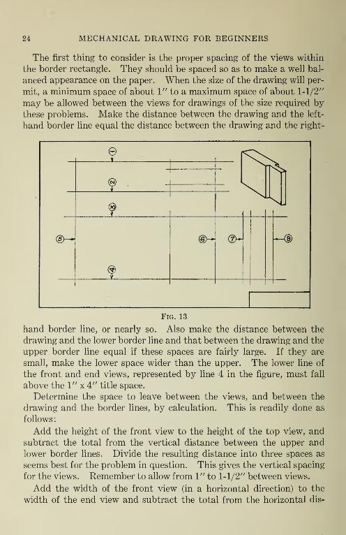
24 MECHANICAL DRAWING FOR BEGINNERS
The first thing to consider is the proper spacing of the views within the border rectangle. They should be spaced so as to make a well bal¬ anced appearance on the paper. When the size of the drawing will per¬ mit, a minimum space of about 1" to a maximum space of about 1-1/2" may be allowed between the views for drawings of the size required by these problems. Make the distance between the drawing and the left- hand border line equal the distance between the drawing and the right-
9 ®
*
f
(D~“^
%
©-*■ Qb~ “*■—®
Fig. 13
hand border line, or nearly so. Also make the distance between the drawing and the lower border line and that between the drawing and the upper border line equal if these spaces are fairly large. If they are small, make the lower space wider than the upper. The lower line of the front and end views, represented by line 4 in the figure, must fall above the 1" x 4" title space.
Determine the space to leave between the views, and between the drawing and the border lines, by calculation. This is readily done as follows:
Add the height of the front view to the height of the top view, and subtract the total from the vertical distance between the upper and lower border lines. Divide the resulting distance into three spaces as seems best for the problem in question. This gives the vertical spacing for the views. Remember to allow from 1" to 1-1/2" between views.
Add the width of the front view (in a horizontal direction) to the width of the end view and subtract the total from the horizontal dis-

WORKING DRAWINGS 25
tance between the right and left border lines. Divide the resulting dis¬ tance into three spaces as seems best for the particular problem in ques¬ tion. This gives the horizontal spacing.
In laying out the lines, proceed as follows: First place the scale on the paper with the edge parallel to the left-hand edge of the paper, and locate points thru which lines 1, 2, 3, and 4 will pass, making the dis¬ tances correspond with the calculation made to bring these lines at the desired distance from the border lines and from each other. Mark all points; then draw the lines in the order shown, using the T-square.
With the scale laid along line 4, lay off points locating lines 5, 6, 7, and 8, and draw these lines in order, using triangle on the T-square. The lines thus drawn locate the boundary lines of the views.
Now draw other lines needed to show the form of the object. Make all lines light and fine with hard pencil, allowing them to overlap at the intersections as shown.
The student should now begin the drawing assigned by the instructor, carrying it thru the constructive stage. Follow the method given in the above explanations.
Dimensioning stage. As already explained in connection with Figs. 11 and 12, in addition to showing the form of an object and the re¬ lationship between all its parts by means of orthographic views, it is also necessary to give dimensions if the drawing is to be used as a guide in construction work. The dimensions are given upon lines, called dimen¬ sion lines, terminated by arrow-heads which point to the lines between which the dimension reads.
The following ideas should be kept constantly in mind while placing the dimensions upon a drawing.
1. Do not consider that you are trying to dimension the drawing, but remember you are trying to place upon the drawing the dimensions of the object.
2. Try to decide just what dimensions will be used by the workman in making the article and give these.
3. Locate dimensions so that they will give the information as clearly as possible.
4. Make numerals clear and definite so they may be easily read.
5. Do not repeat dimensions; that is, show each dimension once only.
Fig. 14 shows in detail the generally accepted conventions for dimen¬ sioning a drawing.

26 MECHANICAL DRAWING FOR BEGINNERS
Dimension lines are light lines upon which the dimension figures are placed. An opening for the numeral is left near the center of the line. Arrow-heads at the ends of the dimension lines indicate the points be¬ tween which the dimension reads.
Extension lines are light lines extending out from the drawing, or into the views themselves, to which the dimensions refer.
All dimension and extension lines 'should be light, continuous lines. In pencil drawings they should be made with the hard pencil. First locate them with very light strokes in the “dimensioning stage,” and
when certain they are correct, finish with a stronger line, making them distinct but still fine, as explained later under "finishing stage.” Have pencil point sharp.
Arrow-heads should be made in size and shape about as shown in Fig. 14. The dimensions for arrow-heads shown in the lower left-hand corner of the illustration may well be used for arrow-heads in drawings of the size made in this course. The size of arrow-heads may vary in different drawings but should be uniform in the same drawing.
Extension lines should extend about 1/8” beyond the dimension line, and a space of from 1/32” to 1/16” should be left between the end of the extension line and the line of the drawing to which it refers.
Dimension lines should be about 1/4” from the nearest line of the drawing or from the nearest dimension line. This will leave room to place the figures on the lines without crowding, and at the same time give a compact, unified appearance to the views.

WORKING DRAWINGS 27
Dimension lines are usually placed outside of the views in order not to obscure the drawing, but they may be placed on the views if this results in greater clearness. It is better to place the dimensions on the views than to use long extension lines that may be difficult to follow.
Dimension figures, or numerals,should be clear and distinct on the fin¬ ished drawing. They should be made large enough to be easily read, but not so large as to be out of proportion to the drawing. Beginners are likely to make figures too small and cramped or too large and sprawl¬
ing. For the size of drawings made in this course, it will be well to make whole numbers about 1/8" high and the total height of fractions about 1/4". This would vary for different sized drawing.
Dimension figures should always be placed at right angles to the di¬ mension lines. Dimension figures on horizontal lines should read from the bottom of the drawing. Those which are on vertical lines should read from the right-hand side of the drawings. On inclined dimension lines the figures should still be placed at right angles to the line, but in such a position as to read most readily from the bottom or the right- hand edge of the drawing. Study the examples given on the various drawings in the text.
Fig. 15 shows four arrangements for dimensions upon the same draw¬ ing. In No. 1 the dimensions are outside of the views, are systemati-

28 MECHANICAL DRAWING FOR BEGINNERS
cally arranged, and are located centrally on the drawing. In No. 2 they are scattered around the outside of the views. In No. 3 they are placed upon the views, and not close to the lines of the drawing. In No. 4 they are irregularly placed and scattered. Other arrangements may also be made. No. 1 is considered the best arrangement, as it brings the dimen¬ sions near the center of the drawing where they are most easily seen. Do not scatter dimensions around the outside of the drawing unless there
is no better way. Also avoid placing them near the center of the views as in No. 3.
Fig. 16 illustrates the grouping of dimensions as opposed to scattering them.
The two-view drawing at the left of the center line shows the dimen¬ sions properly grouped, while the same drawing at the right of the center line shows exactly the same dimensions but they are scattered, making it much more difficult to find them.
Observe that when the dimensions of several parts of an object are measured continuously they should be placed in the same straight line, the extension lines and arrow-heads defining the limits of each. The dimension of the whole, that is, the'sum of the fractional dimensions, should be placed just outside the line bearing the part dimensions, if
possible. Place the longer lines outside the shorter ones so the extension lines
need not cross the dimension lines.

WORKING DRAWINGS 29
Notice that it is best to give the dimensions on the view that best shows the shape of the object. Thus in the illustration here given, Fig. 16, most of the dimensions are placed on the front view as this view shows the distinctive shape of the object most clearly.
Fig. 17 illustrates several methods of arranging arrow-heads and fig¬ ures in placing dimensions upon a drawing.
The arrangements shown in Fig. 17, marked 1, 2, 3, and 4, are used for showing small dimensions that can not well be shown in the ordinary way. In No. 1 the arrow-heads are placed upon short lines outside of the extension lines, and the figure is written between them. In No. 2 the arrow-heads are outside the figure, and placed at the end of a line, called a “leader,” which has an arrow-head at its end, pointing to the place that the figure should occupy. Always rule leaders with a straight edge and draw them so that the figure or note will be in hori¬ zontal or vertical position. In No. 3 the arrow-heads are outside of the extension lines, and the figure is placed at the end of one of the short lines provided with an arrow-head, this line itself serving as a leader. In No. 4 the arrow-heads are inside of the extension lines and the figure placed at the end of a leader as in No. 2. No. 5 shows the arrangement commonly used for all larger dimensions as previously explained.
At No. 6 is illustrated a rule of practice in locating dimensions that the learner may easily break. The incorrect location for this dimension and several correct locations are shown. The rule illustrated here may

30 MECHANICAL DRAWING FOR BEGINNERS
be stated as follows: Never draw a dimension line in such a location that it becomes an extension of an object linef whether the object line be a full or dotted line.
Fig. 18 illustrates the second or dimensioning stage in making a draw¬ ing, as applied to the drawing of the tenon piece, the constructive stage of which has been explained in connection with Fig. 12.
Fig. 18
It is best for the learner to locate all dimensions upon the drawing before carrying any part of it to the finished stage. Do not locate dimensions, however, until all of the views have been completely blocked out, as it will then be easier to determine the best location for the dimen¬ sions. Do not erase any of the construction lines before locating dimen¬ sions, as many of these are used as extension lines and, if erased, must be replaced, making more work on the drawing.
In placing dimensions, use hard pencil for all lines, arrow-heads and numerals, making them very light so they may be easily erased if not properly placed.
The student should now work his problem thru this stage, observing the suggestions given, and placing the dimensions in what seems to be the best location.
Fig. 19 shows a drawing carried thru the finishing stage. This is the same drawing the first and second stages of which have already been ex¬ plained in connection with Figs. 13 and 18.

WORKING DRAWINGS 31
If the drawing is to be finished in pencil, proceed as follows. Observe the following five distinct steps in finishing, and carry them out in the order given and in the manner explained:—
1. Carefully erase all unnecessary lines. 2. Trace all object lines with the medium pencil (2H pencil is good for
this), using round point, medium sharp. Make rather strong, dark lines that stand out well on the paper. First draw all horizontal lines with the T-square, beginning at top of paper and working toward the bottom.
Then draw all vertical lines with the triangle used on the T-square, begin¬ ning at the left side of the paper and working toward the right. Always observe this order in drawing lines. Now, draw inclined lines, if any.
3. Trace all extension and dimension lines with the hard pencil, using a sharp point and making all lines firm and distinct, but fine. Follow the same order as given for tracing object lines.
4. Make all numerals and arrow-heads with the medium pencil, ob¬ serving form and proportions shown in Fig. 14.
5. Trace border lines with medium pencil. The finished drawing should have a neat, clean-cut appearance with
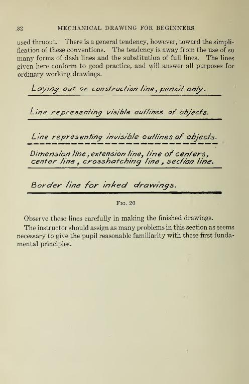
all unnecessary lines and all soiled places cleaned away. Fig. 20 shows the schedule of lines that are commonly used in working
drawings. There is no absolute standard in regard to the conventions used in
mechanical drawing, and no uniformity of practice as to the kind of lines
.32 MECHANICAL DRAWING FOR BEGINNERS
used thruout. There is a general tendency, however, toward the simpli¬ fication of these conventions. The tendency is away from the use of so many forms of dash lines and the substitution of full lines. The lines given here conform to good practice, and will answer all purposes for ordinary working drawings.
Laying out or construction tine} pencil only*
Line representing visible out tines o/ objects.
Line representing invisible outlines of objects.
Dimension line , extension fine, tine of centers, center line f crosshutching fine , section line.
Border fine for in fed drawings.
Fig. 20
Observe these lines carefully in making the finished drawings.
The instructor should assign as many problems in this section as seems necessary to give the pupil reasonable familiarity with these first funda¬ mental principles.

PROBLEMS—SECTION 2 33
Problem 2. Make a three-view working drawing

34 MECHANICAL DRAWING FOR BEGINNERS
Problem 4

PROBLEMS—SECTION 2 35
Problem 5

SECTION 3.
Working Drawings of Objects Generally Rectangular in Form
Having Some Invisible Outlines. Drawings Full Size.
Lettering. In order to place notes and titles upon a drawing prop¬ erly, it is necessary to learn to make freehand letters neatly and rapidly. This ability can be acquired only by careful and constant practice.
Fig. 21 shows the system of making vertical capitals such as may be used for the lettering in this course.
2, 2_ 'll L
2. T 'hi1' € f <IA AA ;|X Vi *11
1 L T H E F N M K Y
x V- W* $s 2 T*’
■ii ii2 s J o 2 fe
X V W A Z U J D P R
e o e» Tv
£ £r DRAW
B 0 0 c G
Fig
s 1. 21
POST
Lay out a half sheet of paper the same as previously used for prac¬ ticing numerals. Use this practice sheet in the same manner as sug¬ gested for practicing numerals, making single letters only, not words and sentences. Repeat each letter a number of times before going on to the next so as to learn the system of strokes and the form and proportion of each letter. Practice all letters in this way in the order given; then fill in the remainder of the sheet with those that are most difficult to make.
Fig. 22 illustrates the use of dash lines, commonly called i(dotted lines ” to represent invisible outlines of objects. The drawing shown here is that of the block shown in the sketch in the upper right-hand corner of the figure.

LETTERING—INVISIBLE OUTLINES 37
When representing objects in orthographic projection, or as views used in a working drawing, the object is looked upon as if it were trans¬ parent. All boundary lines of surfaces must be shown in their proper relation, whether they are visible or invisible to one looking at the out¬ side of the object. The draftsman must imagine that he can look clear thru the object and draw all lines in their proper places, representing those that are visible by full lines and those that are invisible by dash lines. This representation of invisible lines is often absolutely necessary in order to make clear the interior parts of the object.
The dash, or dotted lines used for this purpose should be drawn about as shown in Fig. 20 for the proper appearance in the finished drawing. In drawing these lines first in the constructive stage, they should be made fine and light the same as other lines. The beginner may dot them in the constructive stage in order to avoid confusion, but, after a little experience, all lines may be made full lines in the constructive stage, and the distinction between lines of different character made in the finished drawing. Invisible lines should be composed of dashes about 1/8" long with spaces about 1/32". In drawing broken lines, always make spaces short, no matter how long the dashes may be.
Fig. 23 shows the proper way of joining dotted lines to full lines and
to each other. At No. 1 is shown the correct and incorrect way of connecting dotted
lines to full lines when they meet as shown.

38 MECHANICAL DRAWING FOR BEGINNERS
At No. 2 is given the right and wrong way of connecting a dotted line to a full line when one is an extension of the other.
At No. 3 is shown the right and wrong way of connecting dotted lines when they meet to form an angle.
At No. 4 is shown the correct and incorrect way of connecting one dotted line to another when they meet as shown.
Study these illustrations carefully and observe them strictly when drawing dotted lines.
Problems. In working the problems in this section follow the same procedure as for those in the previous group. Review the explanations given for the previous problems and try to get these fixed so clearly in mind that it will become habitual to work in accordance with them.
The student should make such drawings as the instructor may assign and after each stage of a drawing is completed it should be checked by the instructor before the pupil takes up the next stage in the work.

PROBLEMS—SECTION 3 39
CLAMP STRAP
Problem 7. Make a three-view working drawing

40 MECHANICAL DRAWING FOR BEGINNERS
d ]-1 b
DRAW END VIEW AND GIVE DIMENSIONS.
MAIN BLOCK f X 5
KEY STRIPS i’xjfx 2
GROOVES WIDE, | DEEP.
SANDPAPER BLOCK
Problem 9

PROBLEMS—SECTION 3 41
Problem 10

SECTION 4.
Working Drawings of Objects Generally Rectangular in Shape
Similar to Those in Preceding Sections But Requiring to Be
Drawn to Reduced Scale.
Preliminary explanations. Articles that are too large to be drawn full size must be reduced, or “drawn to scale,” making the drawing smaller than the object. Five of the six graduated faces on the drafts¬ man’s triangular scale contain reducing scales for this purpose. By
( L a. & _J
b-5§ —j TE "TTC 1 G 1 C- L r-1 l i }
\ \
. ' t ; 1 1 -1-1
\ 1 i )
< GIVEN LINE.. MEASUREMENT ^ GIVEN LINE . M EA5UREMENT
WHOLE NUMBER
iCTION
MADE FROM FRACTION
TOWARD WHOLE NUMBER.
" MADE FROM V
TOWARO FRA
Fig. 24
means of these a drawing may be reduced automatically and no com¬ putations are necessary to obtain the desired size and proportions in the drawing.
The method of reading the scale for this purpose is shown in Figs. 24 and 25.
Fig. 24 illustrates the use of the scale when such ratios as 1/2” equals 1”, 3/4” equals 1”, 3/8” equals 1”, etc., are desired between the drawing and the object, that is, 1/2” on the drawing is to represent 1” on the ob¬ ject, etc.
In the example given in the figure, it is assumed that the worker plans to make his drawing to the scale of 1/2” equals 1”, which is a very com¬ mon scale. In this case use the graduated surface of the scale which has the fraction 1/2 marked at one end. Here the largest, or main divisions on the scale are actually 1/2” in length and each of these will represent 1” on the object. In using the scale, learn to think of these divisions as being actual inches, not as half inches. Think of them as smaller inches.

DRAWING TO SCALE 43
The whole numbers are read from the point marked zero toward the opposite end of the scale, while the fractions of an inch are read from the point marked zero in the opposite direction on the division that is still further subdivided for this purpose. When making measurements, place the whole number at the point from which the measurement is to be made, and measure past the zero to the correct fraction, or place the fraction at the point from which the measurement is to be made, and measure past the zero to the whole number. Study the illustration in the figure so as to understand this.
V m 1 _
>— \-z£-«
w - z
>
j_La *
■ -J —
—i---1
.K GIVEN CINE . MEASUREMENT < GIVEN LINE. MEASUREMENT :-':7
MAOE FROM FRACTION
TOWARO WHOLE NUMBER.
MADE FROM WHOLE NUMBER
TOWARD FRACTION.
Fig. 25
This is not the way in which the scale is really designed to be used. The main divisions on the scale are intended to represent feet instead of inches and its use in this way is explained above in connection with Fig. 25. When used as explained above it will be noticed that fractions less than 1/4" are not so easy to read. In the case of the half-inch scale, three of the smallest divisions represent 1/8" and one and one-half of these divisions represent 1/16". This fact makes this use of the scale a little difficult at first, but with a little practice, it is possible for the student, especially if he is not proficient in dividing fractions, to make half scale drawings much more quickly and accurately in this way than by using the regular foot rule or scale.
Half-scale drawings may also be made by using the ordinary foot rule or scale, dividing each dimension by two in order to obtain the distance to lay off with the scale. However, because of the computations in¬ volved, mistakes are more likely to occur when using this method.
Fig. 25 illustrates the use of the scale when the main divisions are con¬ sidered as representing feet instead of inches, as is the case in Fig. 24.

44 MECHANICAL DRAWING FOR BEGINNERS
For this purpose proceed as already explained but consider each of the divisions on the scale as being a foot instead of an inch. The graduated division at the end of the scale thus becomes a small foot rule graduated into inches and fractions of an inch. This is the best way to use the scale for most drawings particularly where such ratios as 1/4" equals 1" and 1/8" equals 1" are to be used.
Observe that 1/4" equals 1", or l/4th scale, is the same as 3" to the foot (written 3" equals I'-O"), and that 1/8" equals 1", or l/8th scale, is the same as 1-1/2" to the foot (written 1-1/2" equals l'-O"). It is easier to think of the scale in terms of "inches to the foot" rather than in terms of "inches to the inch" in most cases where this is possible.
Remember that the size of the object, not the size of the drawing, should be placed upon the drawing. Therefore give the full-size dimen¬ sions on the drawing.
Problems. Make such drawings as may be assigned using the scale as explained. If the explanation is not fully understood, ask the in¬ structor to illustrate.
Problem 11. Make a three-view working drawing

PROBLEMS—SECTION 4 45
TOOL BRACKET.
Problem 12. Make a three-view working drawing
Problem 13. Make a three-view working drawing

46 MECHANICAL DRAWING FOR BEGINNERS
Problem 14. Make a three-view working drawing
FLOWER BOX
Problem 15

SECTION 5.
Working Drawings of Objects Having Inclined Surfaces, That
Is, Surfaces Other Than at Right Angles With Each Other.
Drawings Full Size or Reduced.
Lettering. Lay out another sheet for practice lettering. On this sheet practice making actual words and sentences. In doing this the problem of proper spacing of letters will be encountered. Try to space the letters so that each word will look compact but not crowded; space
the letters so as to give the appearance of equal spacing between the letters. Notice that letters can not actually be spaced equal distances apart in the words, but must be placed so as to appear equally spaced. Study this question of spacing carefully. Leave a generous space be¬ tween words.
A number of such practice sheets should be made during the course, as it is not possible to learn to letter well by doing only what is required on the drawings.
Preliminary explanations. Fig. 26 shows a drawing of an object which has some surfaces at other than right angles to each other. No¬ tice that in the front view the edges of the inclined surfaces appear as lines inclined to the horizontal and show the true angle between these

48 MECHANICAL DRAWING FOR BEGINNERS
surfaces. In the top view these same edges appear as parallel hori¬ zontal lines and in the end view they appear as parallel vertical lines. The line AB in each view of the drawing represents the same line on the object.
The lines AB and CD in the top and end views are called foreshortened lines. They are not shown in their true length in these views as they slant away from the plane of the paper. The surface ABCD in these same views is foreshortened for the same reason.
In order that a line may appear in its true length on any view of a drawing it must be parallel to the paper in the view in question, and in order that a surface may appear in its true size it must be so placed in space as to be parallel to the plane on which it is represented.
There are two ways of dimensioning inclined lines and surfaces. One is by giving the coordinates, the other by angles.
The method used in the illustration in Fig. 26 is that of giving coordi¬ nates. Notice that, when this is done, the vertical and horizontal dis¬ tances from some line of reference to lines that pass thru the point to be located are given. The length of the inclined edge itself is rarely given.
Fig. 27 shows the method of locating inclined lines when dimensioned by angles expressed in terms of degrees. In such a case, the dimension line is drawn as the arc of a circle having its center at the vertex of the

INCLINED SURFACES 49
angle to be measured, as shown in the drawing of the little paper weight
in the figure.
At No. 1 the arrow-heads are outside of the lines and the figure is be¬
tween them.
At No. 2 the arrow-heads are outside of the lines and one of the lines upon which the arrow-heads are placed serves as a “leader” for the fig¬
ure. At No. 3 both arrow-heads and figures are between the lines to be
located.
In each of the above, the arrow-heads refer to the object lines them¬ selves.
In No. 4 both the arrow-heads and the figure are between the lines, one arrow-head referring to an object line and one to an extension line.
At No. 5 two extension lines are used.
When dimensioning angles, any of these arrangements may be used as seems best under the circumstances.
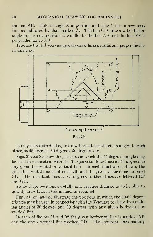
When making drawings of objects having inclined surfaces, it is often necessary to draw lines parallel and perpendicular to each other when these lines can not be drawn with the T-square and triangle in the ordi¬ nary position. Fig. 28 illustrates one method of drawing lines parallel and perpendicular to a given line by means of the triangles.
Let AB represent a given line in any position on the paper. Place triangles X and Y so that the hypotenuse of one is in contact with the hypotenuse of the other. Keep them thus in contact and moving them both together adjust them so that one leg of Y is coincident with
50 MECHANICAL DRAWING FOR BEGINNERS
the line AB. Hold triangle X in position and slide Y into a new posi¬ tion as indicated by that marked Z. The line CD drawn with the tri¬ angle in this new position is parallel to the line AB and the line EF is perpendicular to AB.
Practice this till you can quickly draw lines parallel and perpendicular in this way.
It may be required, also, to draw lines at certain given angles to each other, as 45 degrees, 60 degrees, 30 degrees, etc.
Figs. 29 and 30 show the positions in which the 45 degree triangle may be used in connection with the T-square to draw lines at 45 degrees to any given horizontal or vertical line. In each illustration shown, the given horizontal line is lettered AB, and the given vertical line lettered CD. The resultant lines at 45 degrees to these lines are lettered EF and GH.
Study these positions carefully and practice them so as to be able to quickly draw lines in this manner as required.
Figs. 31, 32, and 33 illustrate the positions in which the 30-60 degree triangle may be used in connection with the T-square to draw lines mak¬ ing angles of 30 degrees and 60 degrees with any given horizontal or vertical line.
In each of figures 31 and 32 the given horizontal line is marked AB and the given vertical line marked CD. The resultant lines making

INCLINED SURFACES 51
angles of 30 degrees and 60 degrees with these lines are marked EF and GH.
In Fig. 33 the given lines are marked AB, CD and EF while the re¬ sultant lines are marked GH and KL.
Study these positions of the triangle and the resultant angles so as to be able to rapidly draw them in this manner as needed.

52 MECHANICAL DRAWING FOR BEGINNERS
Problems. Make such drawings as may be assigned by the instruc¬ tor under this division, applying the principles and methods as explained. Be sure that each step is properly understood and that the correct methods of procedure are used.

PROBLEMS—SECTION 5 53
Problem 16. Make a three-view working drawing
Problem 17. Make a three-view working drawing

54 MECHANICAL DRAWING FOR BEGINNERS
LE-G_5_)‘X3'k Braces 3"
•4 ■ x5"
5AW HORSE
Problem 19. Make a three-view working drawing

PROBLEMS—SECTION 5 55
\_/ —
5 8 -
\ /
COMPLETE FRONT AND TOP
VIEWS AND GIVE DIMENSIONS.
SUPPLY ALL DIMENSIONS
NOT GIVEN IN PROBLEM.
WALL SHELF
Problem 20

SECTION 6.
Working Drawings of Straight Line Objects of Greater Com¬
plexity. Laying Out by Means of Center Lines.
Preliminary explanations. In the drawings that have been made up to this time in this course it has been intended that they should be laid out by first drawing the inclosing forms, or rectangles, to obtain the location of the views on the paper. This method is usually satisfactory
Fig. 34
many objects, however, which being symmetrical in form, the drawing can best be laid out from center lines.
Fig. 34 shows the method of laying out a drawing by means of center lines. The illustration given here is the three-view drawing of the little block shown in the sketch in the upper right-hand corner of the figure.
First draw the center lines marked 1, 2, 3, and 4, which are the center lines for the views, locating them so as to give the desired spacing of the views within the border rectangle. In the example given, center lines are drawn both ways thru each of the views, as each of the views is sym¬ metrical with respect to a center line in both directions. In cases where the views are not symmetrical with the center line, there is no advan¬ tage in drawing such a line, as a rule. Fig. 41 illustrates a drawing in

DIMENSIONING 57
which there is no horizontal center line in the front and end views as these views would not be symmetrical with respect to such a line.
Next locate points on the center lines thru which lines 5, 6, 7, 8, 9,10, 11, and 12 are to be drawn. These points usually can be located best by using the dividers and marking off one-half the required distance each side of the center lines. Locate all points before drawing any of these lines; then draw the lines in the order given.
In a similar manner locate and draw other lines necessary to show the form of the object.
Figs. 35 and 36 show the dimensioning and finishing stages of the drawing blocked out in Fig. 34.
In the second stage, all dimension lines, extension lines, arrow-heads and figures are located in light lines with the hard pencil. Place dimen¬ sion to one side of the center lines, as shown in Fig. 36. Do not use center lines as dimension lines.
When center lines are used, the dimensioning of the drawing is often simplified, as the center lines denote symmetry, and like dimensions on opposite sides of the center lines need not both be given.
Fig. 37 shows the same drawing as that of Fig. 36 but in this case the dimensions are given in opposite directions from the center line, whereas in Fig. 36 the total dimensions of the corresponding parts are given. This is a common method of giving dimensions when it is known that

58 MECHANICAL DRAWING FOR BEGINNERS
Fig. 36
Fig. 37
the workman will lay out dimensions from center lines in making the object.
Fig. 38 shows the same drawing as Fig. 36 dimensioned without center lines.
In finishing, erase all unnecessary lines and trace remaining lines as hitherto explained.

DIMENSIONING 59
Notice that the center lines remain on the drawing as fine, light lines and help to indicate the symmetry of the object.
Problems. Work such problems as may be assigned, using center lines and carefully studying the question of dimensioning.

60 MECHANICAL DRAWING FOR BEGINNERS
Problem 21. Make top and front views. Place paper on the board with long dimension perpendicular to T-square edge, and make the 1" x 4" title space at
bottom of paper; that is, at the narrow end
Problem 22. Make a three-view working drawing

PROBLEMS—SECTION 6 61
Problem 23. Make a three-view working drawing
PEED TROUGH
Problem 24

SECTION 7. Working Drawings of Objects Some Outlines of Which Are Cir¬
cles or Arcs of Circles.
Preliminary explanations. No attempt will be made here to ex¬ plain the proper method of adjusting and manipulating the compasses in drawing circular curves. This should be explained by the instructor when the class is ready to do circular work.
Fig. 39 illustrates .the method of laying out views of an object that is formed partly of cylindrical surfaces.
-t—: V |
4
' r
\
, k
pH® 4
-HD
i
-K§) |-H©
4 -1—
4 d>— ®—
Fig. 39
The method shown indicates the general procedure for an object of this kind, but may need some variation to suit other problems.
First, lay out the center lines 1,2, and 3, locating them so as to bring the views in the desired position on the paper.
Next locate points on the center lines thru which the lines 4, 5, 6, 7, 8, 9, 10, and 11 will pass. Use dividers, when possible, as explained in connection with Fig. 31. Draw these lines in the order of the numbers.
With the compass draw circle marked 12. Also draw arcs of circles representing the rounded corners as shown in the top view.
Draw other lines necessary to complete the views.
In making drawings of objects that have cylindrical forms, it is best to draw first the circular view of the cylinder in the view in which it ap-

CIRCLES AND ARCS 63
pears and then project to the other views to show the rectangular view of the cylinder, rather than to draw first the rectangular view and then project and draw the circle. In other words, it is usually best to draw circles and semicircles before drawing the corresponding straight lines in the other views. Arcs of less than a semicircle are usually connected to tangent lines, these tangent lines being drawn first. This applies to the laying out or constructive stage of the drawing.
When a quarter circle is to be drawn tangent to two lines which meet at a right angle, the method shown in the lower right-hand corner of the top view may be used. This is probably the best way when the circle has a rather large radius, and best for the beginner. For circles with small radii the centers are usually located by trial. The method shown here should be clear without further explanation.
Fig. 40 shows various methods of dimensioning radii and diameters of circles and of locating circles.
Nos. 1 to 5 show the different ways of dimensioning radii of circles. No. 1 is usually used and considered best when the radius is long enough and the center is accessible. Nos. 2, 3, and 4 are used for small radii. No. 5 is used for long radii when the center is not accessible. In Nos. 3, 4, and 5 the center is not shown but the leader must be in line with a radius of the arc which is being dimensioned.
Nos. 6 and 7 show methods of giving diameters when the dimension is given to the circular view.

64 MECHANICAL DRAWING FOR BEGINNERS
No. 8 shows two views of a cylinder and the way to give the diameter when this dimension is given to the rectangular view of the cylindrical surface. In this case it is best to add the abbreviation D. or Dia. after the dimension figure.
Nos. 9 and 10 show the proper method of locating centers of circles. Circles are always located by means of their centers not by means of the circumference. Draw lines thru the centers and locate these lines by
Fig. 41
dimensions referring to some line of the object, or to some other refer¬ ence line such as a center line. Do not give dimensions on center lines.
In giving the dimension of complete circles, the diameter, not the radius, is usually given.
Fig. 41 shows the drawing of Fig. 39 carried to the finished stage. Observe the method of dimensioning the circular curves. When lining in a drawing of this kind, either in pencil or ink, first
draw the circles and arcs of circles, then the straight lines in the proper order.
Notice that the center lines remain as part of the finished drawing. Notice, also, that the curved surfaces appear as curves in the top
view only in this drawing, and that the form of the object appears rec¬ tangular in the other views.
Problems. Make such drawings as the instructor may assign. Study carefully the way the cylindrical surfaces appear in the different views of the drawings so as to become perfectly familiar with the repre¬ sentation of objects of this kind.

PROBLEMS—SECTION 7 65
Problem 26. Make a three-view working drawing

66 MECHANICAL DRAWING FOR BEGINNERS
Problem 27. Make a three-view working drawing
complete end view and
GIVE DIMENSIONS.
MALLET H E.AD
Problem 28

PROBLEMS—SECTION 7 67
Problem 29

SECTION 8. Tracing and Blueprinting. Lettering, Titles, Etc.
Preliminary Explanations. Before beginning to make tracings, the titles and other data should be lettered upon the drawings that have been made so as to trace this data upon the inked drawing at the same time the drawing itself is traced.
Lay out light guide lines in the 1" x 4" space as indicated in Fig. 42. In the second space from the top, place the name or title of the object drawn. In the fourth space, place the scale and the date. In the sixth space, place the student’s name. Try to arrange the title, etc., so as to secure an appearance of balance with respect to the center line of the space, as illustrated in the Fig. 42.
Leave guide lines on the pencil drawing, but do not ink guide lines on tracings or on inked drawings.
Inked tracings are made mainly for the purpose of duplication. Dupli¬ cations are usually made by the blueprint process, the tracing acting as a negative thru which the print is made. Tracings are commonly made upon tracing paper or tracing cloth. Tracing paper will serve the pur¬ pose for the work of this course. It is cheaper than cloth, and is used largely where durability is not essential. A reasonably transparent and good grade of tracing paper should be used.
Tracing is recommended as the first work in inking for two reasons: First, it represents the commonest kind of ink work done in actual com¬ mercial practice, and, therefore, gives experience in the most important

TRACING AND BLUEPRINTING 69
type of inking drawings. Second, if a mistake is made when inking upon drawing paper, it is difficult to correct such mistakes, especially if they are serious ones, and leave the drawing in good condition. Fre¬ quently the drawing is spoiled, and it is necessary to re-draw it in pencil before inking again. This is often discouraging to the beginner and wasteful of time. If the tracing is spoiled, another tracing can be made without making over the pencil drawing. More actual work can be done in the same time this way.
Cut the tracing paper a little larger than the drawing paper and fasten it over the drawing paper with thumb-tacks, having the tacks outside of the drawing paper. Have the tracing paper well stretched and free from wrinkles.
Draw pencil lines to correspond with the trim lines and with the upper and lower edges of the drawing paper. The tracing will be trimmed to these lines when finished.
The instructor will explain and demonstrate the use of the ruling pen and the pen point of the compass.
Proceed with the tracing the same as for finishing a pencil drawing, drawing lines in the same order. Remember to draw all circles and other curves before drawing straight lines. This is especially important in inking if good connections between curves and tangents are to be obtained.
Keep pen points in good condition. Always keep them clean. Have cloth pen-wiper always at hand, and wipe the pen each time just before filling and when it is put away in the case. Keep pen points reasonably sharp.
Always have, tacked to the board at the right-hand side of the paper, a piece of paper of the same kind as that upon which the drawing is being made and test the pen upon this before drawing lines upon the drawing or tracing. Never attempt to draw a line in ink until you are sure the pen is properly adjusted and that it will make just the kind of line you desire. Carelessness as to this may be very costly.
Be careful about blotting. In order to avoid blots, observe the fol¬ lowing cautions:
Always work away from the wet lines. Do not try to draw a line too close to the ruling edge.
Do not try to pick up a triangle while it is close to a wet line, or do not leave it in proximity to such a line. Slide it away from the wet lines as soon as they are drawn, or it may be accidentally pushed against them and cause a blot.
Have the outside of the pen perfectly dry and free from ink.

70 MECHANICAL DRAWING FOR BEGINNERS
Be careful not to place the instruments or the hands upon the lines before they are perfectly dry.
Do not try to erase an ink line until it is thoroly dry. See Fig. 20 for types of lines to be used in ink drawings.
Ink numerals, arrow-heads, letters, etc., with a common writing pen. Use a pen with medium fine point and one that is not too flexible. Place a very little ink on the inside, or concave side, of the pen, using the quill in the cork of the bottle. Do not dip the pen into the ink or have any ink on the back, or convex side. Wipe the pen point often to keep the ink fresh and clean.
Never use blotter on inked lines; they must remain full strength on the finished drawing. Use blotter only to remove surplus ink in case of blots.
Blueprinting. Blueprinting is a method of duplication, using a specially-prepared, sensitized paper somewhat as in photography. The result is a copy of the drawing, having white lines upon a blue background. A frame with glass front is used to hold the tracing and blue-print paper while being printed.
Place the tracing in the frame with the inked, or face side next to the glass. Put the blueprint paper over the tracing with the sensitized side next to it. Close the frame and expose to the light for the proper amount of time. Printing is done in direct sunlight or strong electric light. Special blueprinting machines are used for electric printing. The length of time the print is exposed to the light depends upon the “speed” of the paper, the intensity of the light and the transparency of the tracing. Blueprint paper is made of different printing speeds. The speed of the paper must be known, or tests must be made with small pieces before attempting to make prints; otherwise much paper may be wasted. Bright sunlight is best for making prints. Do not try to print unless the light is good. The paper should be handled only in a dark room or in subdued light.
After exposing prints for the right amount of time, remove from the frame, and wash in clear, running water for a short time. This both develops and fixes the print. A print that has been over-exposed may be washed a longer time, and the lines will become whiter. One that has been under-exposed must not be washed too long or it will wash out light. However, all surplus of the sensitizing solution must be washed
away. Remove prints from the water and hang up to dry. Press with a hot
flat-iron after drying if smooth prints are desired. Trim to the de¬
sired size.

TRACING AND BLUEPRINTING 71
Problems. Make tracings and blueprints of such drawings as the instructor may require. It is expected that tracings will be made of some of the drawings made earlier in the course. Trace easiest ones first, and proceed to more difficult as facility is acquired. Make several tracings before going on to the next section of the course. Other trac¬ ings may be made later as may seem desirable. Some inking directly upon the drawing paper may also be done. In making inked drawings upon the paper, do not line them in with heavy lines before inking, but let the inking take the place of the finishing in pencil.
Work slowly and very carefully at first. Be sure that each line is correct inpencil before inking it and thus avoid costly errors.

SECTION 9.
Working Drawings of More Complex Objects Having Curved
Outlines. Projecting Points from Top View to End View or
from End View to Top View.
The new principle to be learned at this time is the method of project¬ ing from the top view to the end view to lay off the horizontal measure¬ ments in the end view, or of projecting from the end view to the top view to lay off vertical measurements on the top view.
When approaching this problem, bear in mind that measurements on the paper in a vertical direction on the top view are really horizontal
Fig. 43
measurements from front to back on the object and that these are the same as measurements in a horizontal direction on the end view.
The student has already learned to project from top view to front view, from front view to top view and from front view to end view. These projections are made directly by drawing horizontal and vertical lines between the views.
Figs. 43 and 44 show how to project from top view to the end view by using the compass to revolve measurements from the vertical to the

PROJECTION 73
horizontal direction. The drawing shown is that of the block in the sketch in the upper right-hand corner of Fig. 43.
If working from center lines, first lay out center lines of top and front views; in this case line 1 is the only center line used.
Next lay out boundary lines of front and top views, in this case lines 2, 3, 4, 5, 6, and 7.
Now put in the remainder of the lines for these two views so as to com¬ plete the views. Notice that the horizontal lines extend thru the end view.
Next draw the horizontal line No. 8 locating it between the front and top views at any convenient distance below line 3; in this case, call it 1-1/4".
Locate point 0 on line No. 8 so that OA plus OB equals the desired dis¬ tance between the front and side views. In the example given, suppose the distance between the front and side views is to be 2". As stated above, the distance OA in this case is 1-1/4"; therefore OB must be 2"— 1-1/4" or 3/4".
Thru point 0 draw the vertical line 9.
Fig. 43 shows the drawing carried to this stage ready for the projec¬ tion lines to the end view.

74 MECHANICAL DRAWING FOR BEGINNERS
Fig. 44 shows the remainder of the process. From all points in the top view project horizontal lines so that they cut line 9.
With point 0 as a center, draw arcs from the points just located on line 9 by projection, continuing the arcs till they cut line 8.
From points thus located on line 8 draw vertical lines thru the end view. These lines intersecting the projection lines from the front view give the desired points on the end view.
In the figure, the lines of the end view are drawn heavy so as to en¬ able the student to distinguish them more easily. This need not be done, however, until the drawing is carried to the finishing stage.
Now dimension and finish the drawing as for previous problems.
Notice that the three views of any point, as point A, Fig. 44, are lo¬ cated at the intersections of the projection lines drawn from these points. They form, as it were, a “closed circuit.” A pencil point started from point A in the top view following along the projection line to point A in the end view, thence to point A in the front view will re¬ turn to point A in the top view along a vertical line. This fact may as¬ sist in checking correctness of work. Practice tracing points from view to view in this way.
Remember that, in making drawings of objects having circular forms, it is best to draw the circles first and then project these to the other view or views.
Problems. Make such drawings as may be assigned. Apply the principles of projection explained above. Learn to trace points accu¬ rately and quickly from one view to another. Facility in projection is very essential for efficiency in making drawings of this kind.

PROBLEMS—SECTION 9 75
ADJUSTABLE BEARING
Problem 30. Make a three-view working drawing
Problem 31. Make a three-view working drawing

76 MECHANICAL DRAWING FOR BEGINNERS
DRAW TOP VIEW BY
PROJECTING FROM FRONT
AND END VIEWS.
COPY HOLDER FOR STENOGRAPHERS
Problem 33

SECTION 10.
Working Drawings of One-piece Objects Showing Full-section
or Half-section Views.
Preliminary explanations. Fig. 45 illustrates the method of repre¬ senting sectional views when a full section is shown. The illustration given is the top and sectional views of the clearance block for circular saw as shown in the sketch.
When drawing sectional views, the object is represented as if it were cut thru on some given plane, the part of the object between the ob¬
server and the cutting plane removed, and the view of the object drawn as if looking perpendicular to this cut surface.
The purpose of sectional views is to show the interior parts of the ob¬ ject more clearly than can be done by outside views only, in which dotted lines are depended upon to show the interior parts. Sectional views are resorted to only when this greater clearness will result.
In drawing sectional views, all visible lines of the object back of the cutting plane should be drawn, but the invisible lines need not be shown unless necessary to make the form of the object clear.
In sectional views, the parts of the drawing representing the cut sur¬ face, or the parts of the object actually cut thru in the section, are cross-

78 MECHANICAL DRAWING FOR BEGINNERS
hatched, that is, fine, closely-spaced, parallel lines are drawn across these cut surfaces in order to distinguish them from parts of the object back of the cutting plane. These lines are usually drawn with the 45 degree triangle, about 1/16" apart, spaced entirely by eye, and drawn after all the rest of the drawing has been completed. The spacing of the cross- hatch lines may vary with the size of the surface to be cross-hatched.
Fig. 46 shows the way in which half-section views of objects are drawn. In a case of this kind, one quarter of the object is supposed to be cut
away as shown in the sketch in the upper right-hand corner of the figure.
The sectional view is drawn as if looking in a direction perpendicular to one- of these cut surfaces. In the illustration given here, the part of the drawing to the left of the center line in the view which contains the sec¬ tion is half of a front view, and the part to the right of the center line is a half-sectional view of the object. Thus we really have two views in one. This is a common method of representing symmetrical objects when a sectional view is desired. The sectional view may be to the right and the outside view to the left of the center line if desired.
In drawing the cross-hatching lines, it is well to keep in mind the following facts: A cross-hatching line must always stop at a full line, while it can never stop at, but must cross over, a dotted line. If this is remembered, many mistakes in cross-hatching will be avoided.
Problems. Work such problems as may be assigned, representing the sectional views in the way to bring out the form of the object most clearly.

PROBLEMS—SECTION 10 79
LATHE REST CLAMP
Problem 34. Make top and end views and a full-section view in place of front view
Problem 35. Make top view and a half-section view in place of front view. Place paper on board with long dimension perpendicular to T-square and
title space at the lower, short margin

80 MECHANICAL DRAWING FOR BEGINNERS
Problem 36. Draw top view and a half-section view in place of front view. Place paper on board with long dimension perpendicular
Problem 37
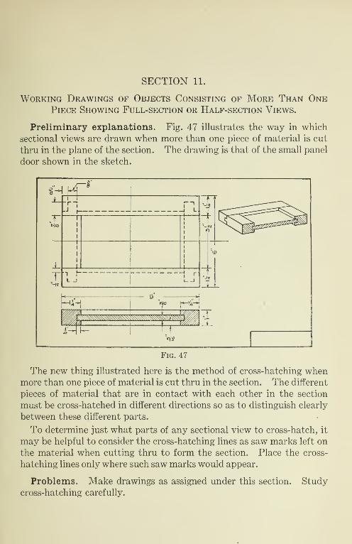
SECTION 11.
Working Drawings of Objects Consisting of More Than One
Piece Showing Full-section or Half-section Views.
Preliminary explanations. Fig. 47 illustrates the way in which sectional views are drawn when more than one piece of material is cut thru in the plane of the section. The drawing is that of the small panel door shown in the sketch.
The new thing illustrated here is the method of cross-hatching when more than one piece of material is cut thru in the section. The different pieces of material that are in contact with each other in the section must be cross-hatched in different directions so as to distinguish clearly between these different parts.
To determine just what parts of any sectional view to cross-hatch, it may be helpful to consider the cross-hatching lines as saw marks left on the material when cutting thru to form the section. Place the cross- hatching lines only where such saw marks would appear.
Problems. Make drawings as assigned under this section. Study cross-hatching carefully.

82 MECHANICAL DRAWING FOR BEGINNERS
Problem 38. Make top and end views and in place of front view make section on center line of holes
Problem 39. Draw top view and make half-section views in place of both front and end views

PROBLEMS—SECTION 11 83
Problem 40
X o c£)
o Id z cc D h
Problem 41

SECTION 12.
Working Drawings of Miscellaneous Objects Representing
Partial Sections, Revolved Sections and Breaks.
Preliminary explanations. Fig. 48 illustrates what is called a “partial section.” Here the drawing is that of the panel shown in the sketch in the figure.
A part of the material is shown cut away, or broken away at one cor¬ ner of the object so as to show the arrangement of the pieces at the joint better than could be done by dotted lines only.
A line, called a “section line," marked by letters at its extremities, is often placed upon the drawing to indicate the plane on which the section is taken when this is not otherwise evident. A note is added to call attention to this line, as illustrated in Fig. 48.
Notice how the cross-hatching lines cross over the dotted lines but always stop at the full lines.
These partial sections may often be thrown in to clear up the form of certain parts of the object without making complete sections.
Fig. 49 illustrates the use of revolved sections and conventional breaks.

REVOLVED SECTIONS AND BREAKS 85
The revolved section is placed directly upon one of the views of the drawing and shows the sectional form of the part to which it relates, as if the object had been cut at this point and the cut surface revolved into the plane of the paper.
When any object, such as a long rod, bar, moulding, etc., is to be drawn, the full length of the object can not be represented, for the scale would need to be so small that the drawing would be impracticable. In
Fig. 49
such a case it is common to represent the object as if part of it had been broken out near the center and the two ends moved together. This shortens the view on the drawing and enables a larger scale to be used. The dimension must give the full length of the object.
No. 1 in the drawing, Fig. 49, is commonly used with any shaped piece simply to indicate that a part has been cut away.
No. 2 is used for rectangular rods or bars, and serves to indicate the form of the section as well as the fact of the break.
No. 3 is used for breaks in round rods.
No. 4 represents a pipe, tube or hollow shaft.
Problems. Make such drawings as may be assigned using careful judgment as to the use of sections in various ways to make clear the form of all parts of the object.

86 MECHANICAL DRAWING FOR BEGINNERS
Problem 42. Make top view, make full section in place of front view, and show partial section on end view as suggested on the plate
by the broken part in the sketch
Problem 43. Make three views and show partial section in front view

PROBLEMS—SECTION 12 87
Problem 44
r > tu:
} mlSS
1 V/f.
i
A Ti
i
L|<\l (M
i f dr
Using one of the designs for pic tore
frame moulding shown be/on/, or an original design made by the student,
make a -front view of a picture frame
to take a g/ass 18" x 24'.
Make the drawing full scafe but use
* breaks' in sides and ends as suggested here.
Show shape of moulding by revolved section and qive all dimensions.
Ma
I o i" __
y l.
“2 i__ wise
_._ .[
.t^i frf -Z N<0
1 ■•-I IiV _J3"
n i6
P1CTURE FRAME
Problem 45

SECTION 13.
Preliminary explanations. The problems contained in this section are partly design problems and relate to courses in woodworking. Stu¬ dents who have not had instruction in woodwork could not be expected to solve these problems well without considerable help from the instruc¬ tor as to joints, fastenings, dimensions of parts, etc. Those who have had woodwork or who are taking such courses should be able to deal with these problems with only reasonable consultation with the instruc¬ tor.
It will be found best to sketch these drawings on squared paper and decide all details before attempting to draw them on the regular draw¬ ing paper. Several sketches may need to be made before the best solu¬ tion is determined upon. Plain paper may be used for sketching but squared paper is better.
Problems. Solve problems as assigned by the instructor. Study the design carefully so as to secure good results as to proportion, form, strength, and other requirements of the structure.
Problem 46. Draw such views as may be required to make complete working drawings

PROBLEMS—SECTION 13 89
Assume c/zmen'Sions one1
ma/re o three-y/ew working e/raw/nq.
Problem 47. Draw such views as may be required to make complete working drawings
Problem 48. Draw such views as may be required to make complete working drawings

90 MECHANICAL DRAWING FOR BEGINNERS
Problem 49. Draw such views as may be required to make complete working drawings
Problem 50. Draw such views as may be reauired to make complete working drawings

INDEX
A Angles:
How to Dimension. How to Draw with Triangles
Arrangement of Views.
Arrowheads: Size and Form of. In Dimensioning Stage. In Finishing Stage. In Inked Drawings.
B Blueprinting.
Blueprint Paper.
Border Lines: Location of. How to Lay Out. Kind of Line. Order in Finishing Stage
Breaks, Conventional.
Page
48 50
22
26 30 31 70
. .70
9, 70
. .18
. .19
. .32
. .31
. .85
C Center Lines:
Laying Out Drawing by.56 Character of.. 32, 59 Dimensioning When Used.57
Circles: Representation of.62 Drawing.62 Dimensioning.63 Tangent to a Line.63 Order of Drawing.62, 64, 69
Compasses, Use of.62
Constructive Stage, Explanation of.23
Conventional Breaks.85
Co-ordinates, Use of in Dimension¬ ing.48
Crosshatching: Explanation of.77 Lines.32, 77 Single-Piece Objects.77 Objects of More Than One Piece... 81
Crosshatch Line, Character of . 32, 77
Curved Surfaces, Representation of.62
D Dash Lines:
Character of.32, 37 Use of.37 How to Connect with Other Lines. . 38
Page
Design Problems.88
Diameters, Dimensioning by Means of.63
Dimension Lines: Explanation of.26 Arrangement of.26,27, 28, 29 Character of.32 In Finishing Stage..31
Dimensioning: Conventions for.26 Rules for.25, 28, 30 Angles.48 Circular Forms.63 Inclined Surfaces.48 From Center Lines.57
Dimensioning Stage, Explanation of.25
Dimensions: Size of.27 Arrangement of.27 Grouping.28
Dividers, Use of in Measuring .... 57
Dotted Lines (see “Dash Lines”)
Drawing Pencils (see “Pencils”)
Drawings: Working.21 Perspective.21 Stages in Making.23
E
End View (see “Side View”)
Erasing.30, 31
Extension Lines, Explanation of. .26
F Figures:
Composition of.17 How to Practice.17 Size of in Dimensions.27 Position of in Dimensions.27 In Finishing Stage.31 In Inked Drawings.70
Filling Pens.70
Finishing Stage: Explanation of.31 Steps in.31
ForeshortenedLinesandSurfaces . 48
Form Description.22
Fractions, Size and Form of. ... 17,27
Freehand Sketching.8,88

92 INDEX
Page Front View:
Explanation of.22 Location of.22
Full Sections.77
H
Half Sections 78
I
Inclined Surfaces: Representation of.47 Dimensioning.48
Inclosing Rectangles, Laying Out by Means of.23
Inking.67
Instruments, List of. 9
Invisible Outlines, How to Repre¬ sent.36
L
Laying Out Drawing by Inclosing Rectangles.23
Laying Out Drawing by Center Lines.56
Laying Out Sheet: For Practice Lettering.16 For Regular Drawing.18
Letters: Composition of.36 Spacing of.47
Lettering : Laying Out Sheet for.16 How to Practice.36, 47 Titles.68
Lines Schedule of.32 Dash Lines.32, 37 Dotted Lines.32, 37 Center Lines.32, 56 Dimension.26, 31, 32 Border.18, 31, 32 Trim.18,19 Crosshatching.32, 77 Foreshortened.48
M
Materials, List of. 9
Measuring: Use of Pencil in.13 Use of Scale in.12
N
Numerals (see “Figures’*)
O Object Lines: Full. Dash...
Orthographic Projection
Page
. . .31,32 31,32, 37
.21
P Paper:
Fastening to Board.11 Kind to Use.9,18 Size of. 9 Blueprint.9, 70 Tracing.9, 68
Parallel Lines, How to Draw .... 49
Partial Sections.84
Pencils: How to Sharpen.12 Kind to Use.9,12
How to Use in Drawing Lines.. 13,15 Pens:
Use of Ruling.69 Common Steel.70
PerpendicularLines, Howto Draw . 49
Plan View: Explanation of.22 Location of.22
Projection: Finding Points by.72 Orthographic.21
R
Radii, Dimensioning by Means of. . 63
Revolved Sections.85
Ruling Pens, Use of.69
S Scale:
Use of in Measuring.12 Use of in Reducing.42,43
Sectional Views: Explanation of.77, 81, 84 Drawing.77, 81, 84
Sections: Half.78 Full.77 Partial.84 Revolved.85
Sharpening Pencils.12
Side View: Explanation of.22 Location of.22
Size Description.22
Spacing of Letters.47
Spacing of Views.24
INDEX 93
Page Stage:
Constructive.23 Dimensioning.23, 25 Finishing.23, 30
Stages in Making Drawing.23
Constructive Stage.23 Dimensioning Stage.25 Finishing Stage.30
Surfaces:
Inclined.47 Curved.62
T Tacks:
Thumb. 9 Order of Inserting.11
Thumb Tacks.9,11
Titles, Lettering of.68
Tracings:
Purpose of.68 How to Make.69
Tracing Paper.9,68
Page Triangles:
Use of in Drawing Vertical Lines... 5 Use of in Drawing Parallel and Per¬
pendicular Lines.49 Use of in Drawing Lines at 45, 30
and 60 Degrees.50
Trim Lines: Location of.18 How to Lay Out.19
T-Square: Use of in Locating Paper.11 Use of in Drawing Horizontal Lines.13
V Views:
Arrangement of.22 Sectional.77 Half-Section.78 Full-Section.77 Partial-Section.84 Spacing of.24
W
Working Drawings: Explanation of.21 Position of Views in.22


MECHANICAL DRAWING TEXTBOOKS Grammar Grade Problems in Mechanical Drawing—Bennett.
A remarkably simple and carefully graded treatment of the fundamentals of mechanical drawing for the use of students in the 7th and 8th 'grades. It combines an abundance of text and simple problems, accompanied by notes and directions.
Problems in Mechanical Drawing—Bennett. A students’ textbook consisting of 80 plates, of problems classified into groups ac¬
cording to principle and arranged according to difficulty of solution. For eighth and ninth grade classes.
Mechanical Drawing Problems—Berg and Kronquist. A direct and concise text adapted for high school students beginning mechanical
drawing. It covers two years work and contains 128 full-page plates—excellent examples of draftsmanship. Text accompanies each plate, giving necessary facts and helpful hints wherever needed. The underlying principles of drafting are thoroly covered and prac¬ tical applications are abundant. The plates tell what to do, almost at a glance, yet prevent mere copy work.
Mechanical Drafting—Miller. A textbook for advanced high school students which presents drafting room prac¬
tice in practical textbook form. It is so written that it may be used with any course of problems and supplements the instruction of the teacher in such a way as to reduce lecture work to a minimum. It is a direct and simple treatment of mechanical drafting, giving due consideration to the needs of the student, the beginning draftsman and the requirements of the best teaching methods. Well illustrated and bound in flexible bind¬ ing, pocket size. A thoroly practical, modern textbook.
Architectural Drawing Plates—Elwood. A collection of 15 plates showing the various details included in the plans for frame
houses. Names and typical sizes are given and much information helpful to the student or draftsman. One plate shows eleven “Plan Studies,’’ another “How Elevations are Worked Up from Plans and Sections.’’ A wonderfully convenient help in architectural drawing classes.
Progressive Steps in Architectural Drawing—Seaman. A textbook describing and illustrating every successive step in drawing of floor
plans, elevations and various details for successful dwellings. Numerous plates illustrate details of doors, windows, mouldings, cornices, porches, etc. Architectural orders shown in practical working form. “Single line sketches’’ illustrate method of practical de¬ signer in planning a house.
Blue Printing—Friese.
Treats of the planning of rooms and equipment for mechanical drawing and blue¬ printing. Presents desirable floor plans for both electric and sunlight printing and describes apparatus. Covers the various papers, including process of sensitizing, tells how to make blue prints and a variety of special prints, including Vandyke negatives, black-line and blue-line prints.
Lettering Card—Maclin.
A card of alphabets. Shows Gothic capital and small letters both vertical and inclined. A helpful guide to the student while learning to letter. Printed on bristol, size 4" x 8". In packets of 10.
Blank Lettering Pads. Pads of ruled paper assist wonderfully in the teaching of lettering. These are
printed in light blue lines on a good grade of paper. They are convenient and prac¬ tical helps, making possible a thoro drill in the fundamentals of lettering, and afford¬ ing a means of noting accurately by student and teacher the development of the ability to letter. Ruled in two styles, one for vertical and one for inclined letters. Size 5%"x7".
Send for “Descriptive Catalog” of books on Manual, Vocational and Industrial Education.
The Manual Arts Press PEORIA, - ILLINOIS


