mechanical design for a humanoid robot · 2015-01-22 · mechanical design for a humanoid mark...
TRANSCRIPT
Mechanical Design for a Humanoid
Robot
by
Mark Gerald Wagstaff
Submitted to the School of Information Technology and Electrical Engineering in partial fulfilment of the requirements for the degree of
Bachelor of Engineering
at the
UNIVERSITY OF QUEENSLAND
October 2001
Supervisor: Dr. Gordon Wyeth

Mark Wagstaff
8/260 Sir Fred Schonell Drive
St Lucia QLD 4067
18 October 1999
Professor Simon Kaplan
Head of School
School of Information Technology and Electrical Engineering
The University of Queensland
St Lucia QLD 4072
Dear Professor Kaplan,
In accordance with the requirements of the degree of Bachelor of Engineering
in the division of Electrical Engineering, I present the following thesis entitled
“Mechanical Design for a Humanoid Robot”. This thesis project was completed under
the supervision of Dr Gordon Wyeth.
I declare that all work submitted in this thesis is my own, except where
acknowledged. This work, to the best of my knowledge, has not been previously
submitted for a degree at The University of Queensland or any other institution.
Sincerely,
Mark Wagstaff

Mechanical Design for a Humanoid
Mark Wagstaff
The following paper, Design of an Autonomous Humanoid Robot, by Wyeth, Kee and
Wagstaff et al. was accepted at the Australian Conference on Robotics and
Automation, Sydney 2001.
Mechanical Design for a Humanoid
Mark Wagstaff
Design of an Autonomous Humanoid Robot Gordon Wyeth, Damien Kee, Mark Wagstaff, Nathaniel Brewer,
Jared Stirzaker, Timothy Cartwright, Bartek Bebel School of Computer Science and Electrical Engineering
University of Queensland St. Lucia, Queensland, 4072
Australia
Abstract This paper describes the design of an autonomous humanoid robot. The robot itself is currently under construction, however the process of designing the robot has revealed much about the considerations for creating a robot with humanoid shape. The mechanical design is a complete CAD solids model, with specific motors and transmission systems selected. The electronic design of a distributed control system is also complete, along with the electronics for power and sensor processing. A high fidelity graphical simulator has been developed, providing important early feedback on critical design decisions.
1 Introduction There are several reasons to build a robot with humanoid form. It has been argued that to build a machine with human like intelligence, it must be embodied in a human like body. Others argue that for humans to interact naturally with a robot, it will be easier for the humans if that robot has humanoid form. A third, and perhaps more concrete, reason for building a humanoid robot is to develop a machine that interacts naturally with human spaces. The architectural constraints on our working and living environments are based on the form and dimensions of the human body. Consider the design of stairs, cupboards and chairs; the dimensions of doorways, corridors and benches. A robot that lives and works with humans in an unmodified environment must have a form that can function with everyday objects. The only form that is guaranteed to work in all cases is the form of humanoid.
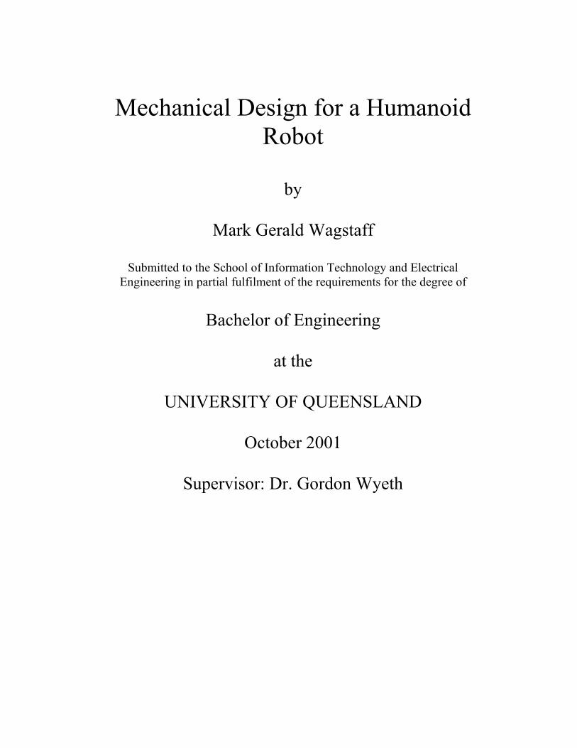
1.1 The GuRoo Project The GuRoo project in the University of Queensland Robotics Laboratory aims to design and build a 1.2m tall robot with human proportions that is capable of balancing, walking, turning, crouching, and standing from a prostrate position. The target mass for the robot is 30 kg, including on-board power and computation. The robot will have active,
monocular, colour vision and vision processing.
The intended challenge task for the robot is to play a game of soccer with or against human players or other humanoid robots. To complete this challenge, the robot must be able to move freely on its two legs. It requires a vision sense that can detect the objects in a soccer game, such as the ball, the players from both teams, the goals and the boundaries. It must also be able to manipulate and kick a ball with its feet, and be robust enough to deal with legal challenges from human players. Clearly, the robot must operate in a completely autonomous fashion without support harnesses or wiring tethers.
These goals are yet to be realised for the GuRoo project. Currently the robot exists as a complete mechanical CAD model (see Figure 1), a complete electronic model and a high fidelity dynamic simulation. The dynamic simulation has been programmed to crouch, jump and balance. The progress to this stage has revealed much about the design considerations for a humanoid robot.
Figure 1: Full CAD model of the GuRoo
humanoid robot.
Mechanical Design for a Humanoid
Mark Wagstaff
1.2 Paper Overview This section has described the motivation for building a humanoid robot, and the specific challenge that has been set for the GuRoo project. The subsequent section will look at other humanoid robot projects, including bipedal walking robots.
The rest of the paper describes the mechanical, electronic and software design of the GuRoo robot. In particular, the paper will detail the mechanical model of the robot and a comparison to the human form, the motors and sensors, the complete electronic design, a full dynamic software simulation of the robot, the software architecture of the robot, and results for balancing and crouching in simulation.
2 Prior Art
2.1 Bipedal Walking Robots Research into bipedal walking robots can be split into two categories: active and passive. The passive or un-powered category (for example, McGeer’s passive dynamic walker [McGeer, 1990]) is of interest as it illustrates that walking is fundamentally a dynamic problem. Passive walkers do not require actuators, sensors, or computers in order to make them move, but walk down gentle slopes generating motion by the hardware geometry. The passive walkers also illustrate the walking can be performed with very little power input.
Active walkers can further be split into two categories; those that employ the natural dynamics of specialised actuators, and those that are fully power operated. Raibert [Raibert, 1986] and later Pratt [Pratt, 1998] have shown some impressive feats of walking and gymnastic ability in robots that have the capacity for energy storage in the actuator. These robots have been shown to have robust and stable performance from relatively simple control mechanisms.
The alternate approach is to control the joints through pre-specified trajectories to a known “good” gait pattern (for example, [Golden, 1990]). This is a simple approach, but lacks robustness to disturbances. This approach becomes more complex when additional layers are added to provide adjustments to the gait for disturbance. Controlling a fully powered biped in a manner that depends on the dynamic model is complicated by the complex dynamic equations for the robot’s motion. Yamaguchi et al. [Yamaguchi, 1998] moved a dynamic torso with significant mass through 2 DOF to keep the Zero Moment Point (ZMP) within the polygon of the support foot. This approach contributed to successful control of the robot, but produces an awkward gait.
2.2 Bipedal Walking Humanoid Robots
There are few examples of autonomous biped walkers that resemble the structure of a human. The Honda company biped robots, P2 and P3 are two of the few examples of such robots [Hirai, 1998]. P3 can walk on level ground, walk up and down stairs, turn, balance, and push objects. The robot is completely electrically and mechanically autonomous. The Sony SDR-3X robot is another example with similar capabilities, although details of the design are yet to be published.
3 Mechanics The mechanical design of the humanoid requires careful and complex tradeoffs between form, function, power, weight, cost and manufacturability. For example, in terms of form, the robot should conform to the proportions of a 1.2m tall human. However, retaining the exact proportions compromises the design in terms of the selection of actuation and mechanical power transmission systems. Affordable motors that conform to the dimensional restrictions have insufficient power for the robot to walk or crouch. This section describes the final mechanical design and how the balance between conflicting design requirements has been achieved.
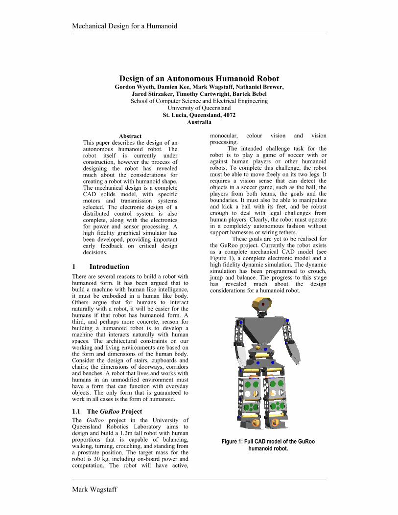
3.1 Proportions The target proportions for the robot are based on biomechanical data of the human form. Figure 2 shows the proportions of the frontal plane dimensions of a 50th percentile male based on data from a United States survey [Dempster, 1965]. The dimensions shown in millimetres indicate the appropriate sizes of anatomical features when scaled to a total height of 1200 mm against the comparable dimensions on GuRoo.
106
247125
66
15561
352
291
289
56
384226
185
123
122 130
220
245
400534
158424
360
218
55 150
22
Figure 2: The proportions of typical human anatomy compared to the matching proportions of GuRoo’s anatomy. The dimensions indicate the sizes for a human scaled to 1.2m in height.

Mechanical Design for a Humanoid
Mark Wagstaff
By comparison, GuRoo is somewhat thickset in the legs, as was dictated by the form of the chosen actuators (see Section 3.3). The spacing between the hips and ankles has been retained, rather than placing the hips and ankles along the frontal centreline of each leg. Our simulation studies showed that the required torques around the roll axes of the hips and ankles becomes excessive if the hips and ankles are spaced too far apart (see Section 5.3).
The body and upper leg of GuRoo are somewhat longer than the counterparts in the human model. This is due to the chain of actuators required for three degrees of freedom in the waist and hips respectively (see Section 3.2). Consequently, the lower leg and the neck and head are shorter to compensate. The overall effect is still convincingly human-like in shape.
The changes in volume required to house the actuators, as well as the mass of the actuators themselves have an effect on the mass distribution. Table 1 shows the mass distribution of GuRoo compared to that of a human. The most notable exception is that the shin and foot are much heavier in GuRoo than the human counterpart, due to the mass of the powerful actuators required in the ankle. The arms are significantly lighter than the human counterpart, as they are significantly inferior in power and do not have hands. GuRoo’s mass distribution is closer to the human distribution than either MIT’s active bipedal walker [Paluska, 2000], or McGeer’s passive dynamic bipedal walker.
Table 1: Comparison of GuRoo mass distribution with human mass distribution, and with the mass distribution of MIT’s M2 bipedal walker and McGeer’s passive dynamic walker.
Body Component
GuRoo mass (kg)
GuRoo Human M2 PDW
Head and Upper torso 7.3 24% 31% 0% 0%
Abdomen and Hips 9.1 30% 27% 51% 50%
Thigh 5.8 19% 20% 22% 30% Shin and Foot 6.4 21% 12% 27% 20%
Arm 1.9 6% 10% 0% 0%
Total 30.5
The other notable point from Table 1 is the total mass of the robot. A 1.2 m tall human would typically be a child approaching his or her 7th birthday, with a 50th percentile mass of 23 kg. A child with mass of 30.5 kg at the same age would be in 97th percentile, indicating that GuRoo is somewhat overweight.
3.2 Architecture The extent to which human joint function can be replicated is another key factor in robot design. Figure 3 shows the degrees of freedom contained in each joint area of the robot. In the cases where there are multiple degrees of freedom (for example, the hip) the joints are implemented sequentially through short links rather than as spherical joints. Other key differences to the human form are the lack of a continuous flexible spine, and the lack of a yaw axis in the ankle. Another point to note is that the roll and pitch axes of the ankle are orthogonal, whereas the human ankle has an angle of about 64° between the roll and pitch axes.
1
2 2
13
3
11
2 2
3
2
Figure 3: The location of the joints in GuRoo,
indicating the degrees of freedom in each joint.
3.3 Motor Choice The key element in driving the mechanical design has been the choice of actuator. The robot has 23 joints in total. The legs and abdomen contain 15 joints that are required to produce significant mechanical power, most generally with large torques and relatively low speeds. The other 8 joints drive the head and neck assembly, and the arms. The torque and speed requirements are significantly less. Factors of cost, weight and availability limited the choice of actuators to rotary DC motors
The 15 high power joints all use the same motor-gearbox combination. The motor is a Maxon RE 36 wound for a nominal voltage of 32V. This motor can provide 88.5 mNm of torque continuously, with a matching current consumption of 1.99 A. The motor has a maximum permissible speed of 8200 RPM. The gearbox has a reduction of 156, with an efficiency of 72%. The maximum continuous generated output torque is 10 Nm, with a maximum output speed of 51 RPM, or 5.3 rad/s. The thermal limits of the motor permit intermittent output torque of up to 19Nm. Each motor is fitted with an optical encoder for position and velocity feedback. The total mass of the motor/gearbox/encoder unit is 0.85 kg.
The 8 low power joints are Hi-Tec RC servo motors model HS705-MG. These motors

Mechanical Design for a Humanoid
Mark Wagstaff
have an integrated gearbox and have rated output torque to 1.4 Nm, at speeds of 5.2 rad/s. These also have potentiometer feedback and built-in control and power electronics. They require 6V power, and a pulse width modulated signal to indicate desired position. The mass of each unit is 0.125 kg.
4 Electronics A distributed control network controls the robot, with a central computing hub that sets the goals for the robot, processes the sensor information, and provides coordination targets for the joints. The joints have their own control processors that act in groups to maintain global stability, while also operating individually to provide local motor control. The distributed system is connected by a CAN network. In addition, the robot requires various sensor amplifiers and power conversion circuits.
VisionProcessor
iPAQ
Peripheral Port
CentralController
Arm and NeckController
USB
Right Thighand Hip
Controller
WaistController
Right Kneeand AnkleController
Left Thigh andHip Controller
Left Knee andAnkle
Controller
CAN Bus
CentralHub
Figure 4: Block diagram of the distributed control system.
4.1 Computing 4.1.1 Central Hub The central control of the robot derives from a hub of three heterogeneous microprocessors that provide coordination between joints, integrate sensor information, and process the vision input. This hub also provides communication to the outside world through user interfaces and communication peripherals.
The primary component of the central controller is an iPAQ pocket pc from Compaq. The iPAQ features a 208 MHz StrongARM microcontroller, 32 Mb of RAM and a 320 x 240 colour screen. The screen is touch sensitive allowing stylus input of text and graphics. The iPAQ has 16 Mb of Flash ROM to store the operating system. The iPAQ in the GuRoo operates with Windows CE. As well as the touch screen interface, the iPAQ is equipped with a speaker and microphone, a joypad, and four push-buttons. It has an infra-red interface for external communication.
The second component of the central hub is a TMS320F243 microcontroller that
acts as an adapter and filter for the robot’s internal CAN network (see Section 4.1.3). The microcontroller communicates with the robot’s distributed control system through the CAN network, and to the iPAQ through the iPAQ’s USB serial communication port. The microcontroller also manages the power supply (see Section 4.2.3) providing centralised control of the robot power supply in the event of system failure. This microcontroller is the same device used in the joint controllers (see Section 4.1.2).
The final component of the central is the vision processing board. This board has been developed for the ViperRoos robot soccer team [Chang, 2001] and features a 200 MHz Hitachi Super-H SH4 microcontroller, an FPGA-based programmable camera and bus adapter, 16 Mb of RAM, 8 Mb of flash ROM, and 512 kb of fast SRAM for video caching. The board interfaces to the 100 pin parallel peripheral bus on the iPAQ to provide real time visual display on the iPAQ’s colour screen. The vision input comes from a custom digital CMOS camera, based around the OV7620 camera chip from OmniVision, which can provide 640 x 480 images at up to 25 fps. The camera can provide data in YUV or RGB formats, and can be programmed to only send data from selected areas of the sense region.
4.1.2 Joint Controllers The TMS320F24x series is a 32 bit DSP designed for motor control. The availability of the Control Area Network (CAN) module in this series, along with bootloader programmable internal Flash memory makes the device particularly attractive for this application. Furthermore the device features 8k words of internal flash memory, 8 PWM channels with deadband generation, quadrature input circuitry, an 8 channel 10 bit analog to digital converter with a conversion time of 800ns, a power drive protection external interrupt, and a 50ns instruction time. The TMS320F241 from Texas Instruments operates at 20MHz, and can read the A/D converter, calculating a PID control law, current limit, and generate the required PWM output, in under 10 µs [Wyeth, 2001]. In this application, we use the TMS320F243, which has an external bus that is used for attaching additional sensor interfaces. Five controller boards control the 15 high power motors, each board controlling three motors. A sixth controller board controls the eight RC servo motors.
4.1.3 Internal Network The CAN bus is a highly reliable standard developed by Robert Bosch GmbH for use in the automotive environment. It is a multi-master system, with sophisticated error checking and arbitration, so that any high priority message will always get through first without corruption by other messages. All data

Mechanical Design for a Humanoid
Mark Wagstaff
contained in each packet (up to eight bytes) is also checked with a Cyclic Redundancy Check (CRC) error-checking scheme that can correct up to five random errors, and will be automatically retransmitted if not correct. The network operates at up to 1 Mbit/sec.
4.2 Power 4.2.1 Drive Power Electronics The drive power electronics is based on a switch mode power stage, requiring only a single supply rail and having an efficiency over 90%. This efficiency results in several advantages such as small size, lower cost power devices and less heatsinking. The H-Bridge channels are driven from separate PWM outputs of the DSP, allowing the deadband features of the PWM peripheral to be used, along with the immediate (<12ns) shutdown of these pins in the event of a fault which triggers the Power Drive Protect Interrupt (PDPInt) pin on the DSP.
A integrated solution was chosen for this design – the SGS-Thomson L6203. This device uses low on-resistance and fast switching MOSFETs, to give maximum efficiency and best control. The voltage limit of the devices is 48V, and the total continuous RMS current limit is 4A. This is a good match to the chosen motors and batteries. The total on-resistance of the power devices is 0.3Ω. The cost of the device is low, compared to a discrete solution, and the volume and mass of the electronics is minimised by the choice of an integrated solution.
4.2.2 Battery Packs The power for the 15 high power motors is provided by 4 x 1.5Ah 42V NiCd packs. These packs are effectively paralleled to a common bus (see Section 4.2.3). The packs are chosen to give 20 minutes of continuous operation. The power for the 8 low power motors is derived from a single 3Ah 7.2 V NiCd battery pack. The power for the control electronics is derived from a second single 3Ah 7.2V NiCd pack. The voltage from this pack is distributed to the various boards that require power where it is regulated locally.
4.2.3 Power Regulation Connecting NiCd batteries in parallel can be extremely hazardous to the life of the batteries. Uneven charging and discharging characteristics between packs can lead to uneven load sharing and high current circulation between packs. The power from each pack is controlled through switch mode buck converters to provide even current sharing between packs, providing a voltage bus at marginally below the lowest battery voltage.
4.3 Sensing 4.3.1 Joint Sensing Current sensing is performed in the high power joints by a 0.01Ω resistance in the ground leg of the H-Bridge. The voltage from these sense resistors is amplified by differential amplifiers and measured by the ADC. Current is also checked against a screwdriver adjustable hard limit that is used to trigger the Power Drive Protect interrupt. The position feedback from the encoders on the high power joints provides a count on every edge of both quadrature channels. This provides 2000 counts per motor revolution from the 500 count encoder wheels. In addition, each DSP can measure the bus voltage, and the temperatures of the MOSFETs and motors.
4.3.2 Motion Sensing In addition to the sensing in each joint, and of course the visual feedback, the robot features 2 x 2-axis accelerometers to provide information about the torso’s dynamic behaviour and the relationship to the vertical gravity force. While it is impossible to resolve the motion components of the body’s acceleration from the effects of gravity, these sensors may be able to provide information with regard to disturbances while walking – playing a similar role to the human middle ear.
Provision has also been made for the contact switches in the feet and in the joints. These switches may prove useful for determining when contact is made with the ground, or initialising joints at robot start up.
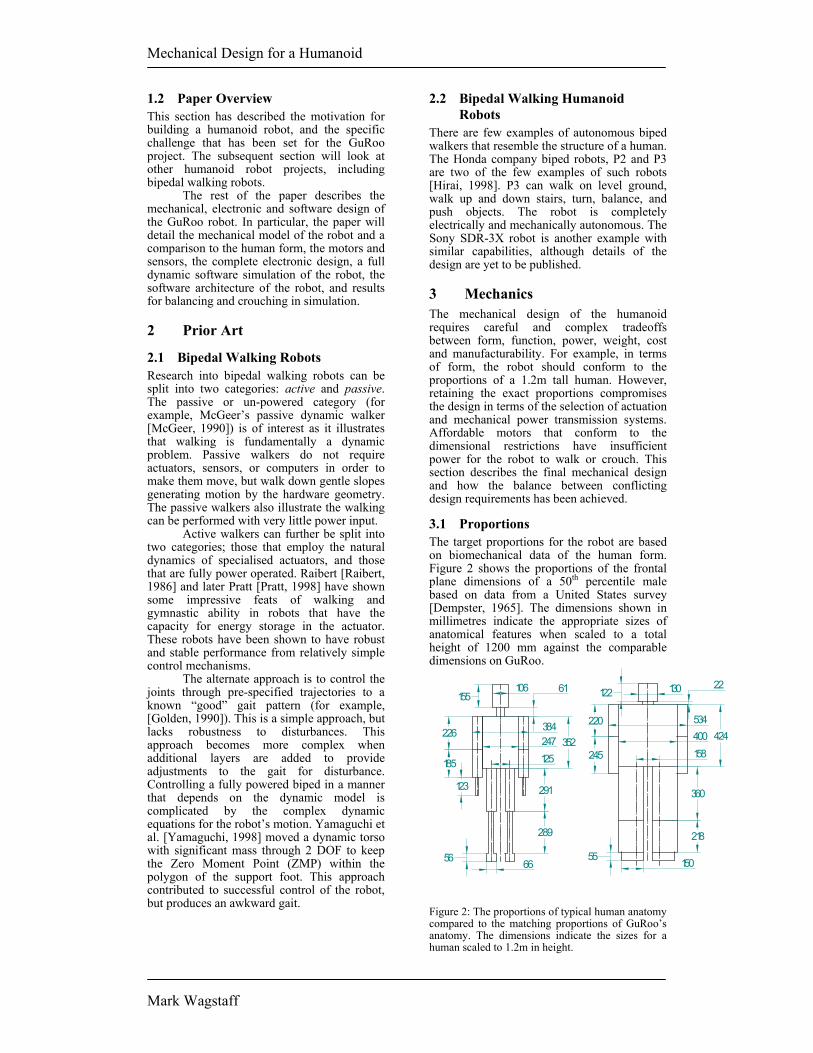
5 Software The software consists of four main entities: the global movement generation code, the local motor control, the low-level code of the robot, and the simulator. The software is organised to provide a standard interface to both the low-level code on the robot and the simulator. This means that the software developed in simulation can be simply re-compiled to operate on the real robot. Consequently, the robot needs a number of standard interface calls that are used for both the robot and the simulator. Figure 5 shows modularisation of the software, and the common interfaces.
Mechanical Design for a Humanoid
Mark Wagstaff
GaitGeneration
MotorControl
ReadTrajectoryCAN interruptTimer interrupt
CAN
_rea
d
TX_p
acke
t
Get
_enc
oder
s
Get
_cur
rent
s
Set_
PWM
s
SetpointsiPAQ
DC joint controller x 5
SetPosition
CAN
_rea
d
Set_
PWM
s
RC jointcontroller
CAN interrupt
Robot Low Level Code / Simulator
Figure 5: Block diagram of common software modules and the interface used to both the real
robot and the simulator.
5.1 Simulator At present, all evaluations of the robot have taken place in a high fidelity dynamic simulator. The simulator is based on the DynaMechs project [McMillan, 1995]. DynaMechs is an object-oriented, open source code library that provides full dynamic simulation for tree-structured robots having a star topology. The algorithms are capable of simulating fixed and mobile bases. The library is based on efficient recursive algorithms for the dynamic calculations, and provides graphical display of the robot in an OpenGL environment.
The simulator uses the DynaMechs package as the core, with additions to simulate specific features of the robot such as the DC motors and motor drives, the RC servos, the sensors, the heterogeneous processing environment and the CAN network. These additions provide an identical interface between the dynamic graphical simulation and the controller and gait generation code. The parameters for the simulator are derived from the CAD models and the data sheets from known components. These parameters include the modified Denavit-Hartenberg parameters that describe the robot topology, the tensor matrices of the links and the various motor and gearbox characteristics associated with each joint. The surface data from the CAD model is also imported to the simulator for the graphical display.
The simulator uses an integration step size of 500µs and updates the graphical display every 5ms of simulated time. When running on 1.5 GHz Pentium 4 under Windows 2000, the simulation updates all 23 joints at a very useable 40% of real time speed.
5.2 Joint Controller Software For the high power DC motor joints, the simulator provides the programmer with readings from the encoders and the current
sensors, based on the velocities and torques from the dynamic equations. In the case of the RC servos, the simulator updates the position of the joints based on a PD model with a limited slew rate. The programmer must supply the simulator with PWM values for the motors to provide the control. The simulator provides fake interrupts to simulate the real events that are the basis of the control software.
There are two types of joint controller boards used in the robot – five controller boards control the fifteen high power motors and one controller controls the eight low power motors. The controller software for the low power motors is a single interrupt routine that is triggered by the arrival of a CAN packet addressed to the controller’s mailbox. The routine reads the CAN mailbox for the change in position sent by the gait generation routine. The PWM duty cycle that controls the position of the RC servos is varied accordingly.
The control loop for the high power controllers has two interrupt routines. As for the low power controller, an interrupt is executed upon receipt of trajectory data in the CAN mailbox. The data is used to set the velocity setpoints for the motor control routine. There is also a periodic interrupt every 500 µs to run the motor control software. The motor control routine compares the error between velocity setpoint and the encoder reading and generates a PWM value for the motor based on a Proportional-Integral control law. The routine also checks the motor current against the current limits, and adjusts the PWM value to prevent over-current situations.
5.3 Motion Generation Software To this point, the software for motion generation has been used to test the designed geometries and chosen motors in the simulator. The software uses only local joint feedback; it does not use feedback from the joint sensors in a global sense or use the motion sensors to modify the motion to maintain balance. The tests are run without current limiting in the local control loop to evaluate worst-case performance.
The first test motion is a crouch with a return to the standing position. This test has been designed to evaluate the required torques in the pitch joints of hip, knee and ankle. The worst-case results for the knee joint are shown in Figure 6. The second test motion is a lean to balance over one leg, designed to evaluate the required torques in the roll joints of hip and ankle. The joints are driven according to the following equations. The worst-case results for the ankle are shown in Figure 7. In both of these worst cases, the current consumption only briefly exceeds the continuous current rating, and the motor stays within thermal limits.

Mechanical Design for a Humanoid
Mark Wagstaff
Motor Values from Knee Joint
-10-8-6-4-20246
0 1 2 3 4 5 6 7 8 9 10Time (s)
Speed (RPM)
Voltage (V)
Current (A)
Figure 6: Simulation results for knee motor during a squatting movement. The movement
cycle time is 10 seconds.
Motor Values from Ankle Joint
-6-4-202468
1012
0 1 2 3 4 5 6 7 8 9 10Time (s)
Speed (RPM)
Voltage (V)
Current (A)
Figure 7: Simulation results for ankle motor during a balancing movement. The movement
cycle time is 10 seconds.
6 Conclusions This paper has illustrated the design of a practical, affordable, autonomous, humanoid robot. The robot is well proportioned in relation to the human form, with most of the major degrees of freedom of the human body implemented. The robot design has a distributed control design with processors dedicated to each of the key roles around the robot. Investigations of the CAD design using a high fidelity simulation have shown that robot is capable of crouching and balancing. [Note for reviewers: This project involves a large team who intend to have the real robot constructed and walking by September. The final paper will have further results, and the conference presentation is likely to feature a video, and possibly the robot itself.]
References [Chang, 2001] M. Chang, B. Browning and G.
Wyeth. ViperRoos 2000. RoboCup-2000: Robot Soccer World Cup IV. Lecture Notes in Artificial Intelligence 2019. Springer Verlag, Berlin, 2001.
[Dempster, 1965] W.T.Dempster and
G.Gaughran. Properties of body segments based on size and weight. American Journal of Anatomy,1965.
[Golden, 1990] J. A. Golden and Y. F. Zheng. Gait Synthesis For The SD-2 Biped Robot To Climb Stairs. International Journal of Robotics and Automation 5(4). Pages 149-159, 1990.
[Hirai, 1998] K. Hirai, M. Hirose, Y. Haikawa, and Takenaka. The Development of Honda Humanoid Robot. IEEE Conference on Robotics and Automation, 1998.
[Hodgins, 1995] J. K. Hodgins, W. L. Wooten, D. C. Brogan, and J. F. O’Brien. Animating Human Athletics. In Computer Graphics, (Siggraph 1995).
[McMillan, 1995] S. McMillan, Computational Dynamics for Robotic Systems on Land and Underwater, PhD Thesis, Ohio State University, 1995.
[McGeer, 1990] T. McGeer. Passive Dynamic Walking. International Journal of Robotics Research, 9(2):62-82, 1990.
[Paluska, 2000] D.J. Paluska, Design of a Humanoid Biped for Walking Research, Masters Thesis, MIT, 2000.
[Pratt, 1998] J. Pratt and G. Pratt. Intuitive Control of a Planar Bipedal Walking Robot. IEEE Conference on Robotics and Automation, 1998.
[Raibert, 1986] M. H. Raibert. Legged Robots that Balance. MIT Press, Cambridge, MA, 1986.
[Wyeth, 2001] Wyeth G.F., Kennedy J. and Lillywhite J. (2000) Distributed Digital Control of a Robot Arm, Proceedings of the Australian Conference on Robotics and Automation (ACRA 2000), August 30 - September 1, Melbourne.
[Yamaguchi, 1998] J. Yamaguchi, S. Inoue, D. Nishino, and A. Takanishi. Development of a Bipedal Humanoid Robot Having Antagonistic Driven Joints and Three DOF Trunk. Proceedings of the 1998 IEEE/RSJ Conference.

Mechanical Design for a Humanoid
Mark Wagstaff i
Acknowledgements
The following people deserve thanks for their contribution to this thesis:
Members of the GuRoo project team and the occupants of Axon room 311. In
particular, Damien Kee and Andrew Blower for helping to maintain some level of
sanity with their endless palaver during the many late nights endured during the
course of the project. David Prasser and Andrew “FIGJAM” Smith also deserve
mention for their unforgettable quotes mentioned herein.
My supervisor, Dr. Gordon Wyeth. Gordon’s vision and drive provided much
motivation for the members of the team throughout the year. His efforts in gaining
extra funding for the project were also much appreciated.
The staff of the electrical workshop, especially Bill Slack and Keith Lane. Their
advice, dedication and positive attitude to an extremely optimistic project has been
admired and appreciated by all involved.
Last, but by no means least, my family for putting me in a position to be able to
complete this thesis. In particular, I would like to thank my Dad for his technical
advice through out the year, and my Mum for putting up with me not visiting home as
often as I should due to spending many of my weekends in the lab.

Mechanical Design for a Humanoid
Mark Wagstaff ii
Abstract
This thesis discusses the mechanical design of the UQ Humanoid Robot, known as the
GuRoo. There are few current working examples of humanoid robots in the world
today. Those that exist are extremely expensive and have been over a decade in
development.
The design presented in this thesis provides a relatively low-cost solution for the
mechanical framework of a humanoid robot. It is has been created with ease of
manufacture and the possibility of building a team of humanoid robots quickly in
mind.
This thesis will evaluate mechanical arrangements of links and joints, discuss the
integration of the mechanical design with actuators, discuss mechanical component
selection, and outline details of manufacture of the robot. Technical drawings used in
the construction of the robot will also be included. Sensor selection will also be
discussed, although much of this is yet to be implemented on the robot.

Mechanical Design for a Humanoid
Mark Wagstaff iii
Table of Contents
ACKNOWLEDGEMENTS I
ABSTRACT II
TABLE OF CONTENTS III
TABLE OF FIGURES VI
CHAPTER 1 – INTRODUCTION 1
1.1 The Problem 1
1.2 The Approach 2 1.2.1 Humanoid Aesthetics 2 1.2.2 Actuation 3 1.2.3 Simulation 3
1.3 Statement of Achievements 4
1.4 Chapter Outline 4
CHAPTER 2 – LITERATURE REVIEW 6
2.1 Initial Concept 6
2.2 Human Body Mechanics 6 2.2.1 Link Lengths and Proportionality 6 2.2.2 Joint Location and Axes of Rotation 7 2.2.3 Mass parameters 9
2.3 Initial Simulation 9
2.4 Actuation 9 2.4.1 Shadow Biped Robot 9 2.4.2 Honda ASIMO 10 2.4.4 MIT Leg Lab’s M2 12
2.6 Sensors 12 2.6.1 Joint Position Feedback 12 2.6.2 Balance 13
CHAPTER 3 – DESIGN PROCESS AND SPECIFICATION 14
3.1 Design Process 14
3.1 Achieving Humanoid Aesthetics 14

Mechanical Design for a Humanoid
Mark Wagstaff iv
3.1.1 Specification of Height and Weight 14 3.1.2 Specification of Link Parameters 16
3.2 Initial Simulator Model 18
3.3 Development of CAD model 18
CHAPTER 4 – LEG DESIGN 20
4.1 Overview 20 4.2.1 Actuator 22 4.2.2 Boss 23 4.2.3 Lazy-end shaft 24 4.2.4 Lazy-end bearing 26
4.3 Foot 26
4.4 Ankle 28
4.5 Lower Leg 30
4.6 Upper Leg - Yaw 33
4.8 Upper Leg – Abduction 36
4.9 Hip Assembly 37
CHAPTER 5 – ARM DESIGN 41
5.1 Overview 41
5.2 Shoulder and Upper Arm 42
5.3 Lower Arm 44
CHAPTER 6 – UPPER BODY 45
6.1 Overview 45
6.2 Torso 46
6.3 Spine 48 6.3.1 Pitch 48 6.3.2 Roll 49 6.3.3 Yaw 51
6.4 Neck and Head 53
CHAPTER 7 – RESULTS AND DISCUSSION 54
7.1 Results 54

Mechanical Design for a Humanoid
Mark Wagstaff v
7.1.1 State of manufacture 54 7.1.2 Proportions and mass properties 55 7.1.3 Walking Ability 57
7.2 Manufacturing Challenges 57
CHAPTER 8 – FUTURE WORK AND CONCLUSION 58
8.1 Future Work 58 8.1.1 Foot Redesign 58 8.1.2 Balance Sensors 59 8.1.3 Joint Motion Sensors 59
8.2 Conclusion 60
REFERENCES 61

Mechanical Design for a Humanoid
Mark Wagstaff vi
Table of Figures
Figure 1.1: Screen Grab from Initial Simulator 3
Figure 2.1: Limb Dimensions of US male age 6 7
Figure 2.2: Leg joint rotations as seen in the sagittal, coronal and transverse
planes. 8
Figure 2.3: Shadow Biped 10
Figure 2.4: Honda ASIMO 10
Figure 2.5: Sony SDR-3X 11
Figure 2.6: MIT Leg Lab’s M2 12
Figure 3.1: Design Process Flowchart 14
Figure 3.2: Limb Dimensions of the GuRoo 16
Figure 3.3 Degrees of Freedom of the GuRoo 17
Figure 3.4: Lego Models 18
Figure 3.5 (a) First complete CAD model, August 01 (b) CAD model as at 05
October 01 19
Figure 4.1: Leg Assembly 20
Figure 4.2: (a) Skeleton Lower Leg Model (b) Detailed Lower Leg Model 21
Figure 4.3: Motor Assembly 23
Figure 4.4: Boss 24
Figure 4.5: “Lazy end” Shaft 25
Figure 4.6: Assembly view of shaft, links and bearing. 25
Figure 4.7: Foot Assembly 26
Figure 4.8: Ankle Shaft – Foot interface 27
Figure 4.9: Ankle Assembly 28
Figure 4.10: Old Ankle Location 29
Figure 4.11: Revised Ankle Location 30
Figure 4.12: Lower Leg Assembly 31
Figure 4.13: Original Panel Design (Welded) 32
Figure 4.14: Revised Panel Design (Angle) 32
Figure 4.15: Upper Leg Rotation Assembly 34
Figure 4.16: Spigot for Thrust Bearing 35
Figure 4.17: Flexion Assembly 36

Mechanical Design for a Humanoid
Mark Wagstaff vii
Figure 4.18: Abduction Assembly 37
Figure 4.19: View of hip joint from underneath. 38
Figure 4.20: (a) Hip design August 2001 (b) Hip design October 2001 39
Figure 4.21: Torsion Spring Mounting Arrangement 40
Figure 5.1: Arm Assembly 41
Figure 5.2: Location of servo motor for shoulder 42
Figure 5.3: Shoulder Assembly 43
Figure 5.4: Upper Arm Assembly 43
Figure 5.5: Lower Arm Assembly 44
Figure 6.1: Rear view of torso assembly 45
Figure 6.2: Side on view of GuRoo 46
Figure 6.3: Torso as at May 2001 47
Figure 6.4: Torso as at 15 Oct 2001 48
Figure 6.5: Spine Assembly 49
Figure 6.6: First Degree of Freedom in Spine (Pitch) 50
Figure 6.7: Second Degree of Freedom in Spine (Roll) 50
Figure 6.8: Original Spine Yaw Link May 2001 51
Figure 6.9: Spine Yaw Assembly 52
Figure 6.10: Spine and Torso Assembly 52
Figure 6.11: Head Assembly 53
Figure 7.1: Motor Assembly with Boss fitted 54
Figure 7.2: Lower Leg Assembly 55
Figure 7.3 Human vs. The GuRoo (Dimensions in mm) 56

Mechanical Design for a Humanoid Chapter 1 – Introduction
Mark Wagstaff 1
Chapter 1 – Introduction “No one can stop us. We’re on a mission from Gordo.” Dave Prasser, May ‘01 The world’s premier robot soccer competition, RoboCup, is an annual event that was
held for the fifth time in 2001. In previous years, the competition has focused on
small, wheeled robots playing on ping-pong table sized fields. Recently, all that
changed. A league for humanoid robots up to 1.2m tall has been created. Teams from
such technological giants as Sony and Honda take part, spending millions of dollars to
achieve the ultimate in robotics – the humanoid. The supreme goal of RoboCup is to
create an autonomous robot soccer team that can defeat the human world cup soccer
champions by 2050.
In order to maintain its reputation as a leader in robotics research, the University of
Queensland has created a humanoid robot research team. Each team member is
responsible for a particular portion of the robot. This thesis will evaluate mechanical
arrangements of links and joints, discuss the integration of the mechanical design with
actuators, discuss mechanical component selection, and outline details of manufacture
of the robot. Technical drawings used in the construction of the robot will also be
included. Sensor selection will also be discussed, although much of this is yet to be
implemented on the robot.
1.1 The Problem The ultimate goal of the humanoid (known hereafter as the “GuRoo”) project is to
build an autonomous humanoid robot capable of competing in the RoboCup
humanoid soccer competition. Although a robot that can play soccer may initially
appear to be of only entertainment value, it can be shown that bipedal robots have a
significant future in robotics applications. Bipedal robots have advantages over
conventional wheeled or tracked robots. They are more easily capable of interacting
with the built environment, as they behave similarly to those for which it is intended –
humans. In order to allow maximum interaction with the built environment, it is
important to ensure that the motion of the robot is as similar as possible to that of
humans. To this end, the robot must have a large number of degrees of freedom,

Mechanical Design for a Humanoid Chapter 1 – Introduction
Mark Wagstaff 2
acting in axes corresponding to human joints. Also, link lengths must be similar to the
corresponding human limbs, as must be the centres of gravity of the links.
1.2 The Approach The design of the robot is primarily centred on creating motion similar to that of
humans. As such, link lengths, joint positions and centres of gravity are designed to
correspond to that of humans. Positioning and orientation of joint actuators was
determined by the axes through which the joint was required to rotate and the shape
and volume of the space available to mount the actuator in. In addition to these
criteria, weight saving is a major issue. In order for the robot to be actuated by
conventional DC motors, the materials used in the construction of the robot must be
as light as possible. Perhaps the greatest limiting factor of all is cost. While it has not
directly affected component selection for the mechanical frame of the robot, it has
limited the power/weight ratio of the joint actuators. This has provided many
challenges to the mechanical design of the robot. Before construction of the robot,
thorough simulation was carried out using DynaMechs1. This simulation phase of the
design process has allowed the mechanical team to identify many problems which
otherwise would not have been discovered until after the robot was built.
1.2.1 Humanoid Aesthetics
One of the largest hurdles faced by builders of humanoid robots is ensuring that the
final product does actually appear humanlike. This requirement was the central
constraint of the mechanical design. The human body was used as a model for
determining link lengths and the rotational axes of joints. In order to allow the robot
to move like a human, the number of degrees of freedom in the robot must correspond
to those of a human. This resulted in 23 degrees of freedom – a complex robot by any
standard.
Mechanical Design for a Humanoid Chapter 1 – Introduction
Mark Wagstaff 3
1.2.2 Actuation
In addition to the required aesthetics of the robot, the method of actuation of joints
also plays a large part in determining mechanical design. The factors to be considered
when incorporating actuators into the design include: type of actuation (revolute or
linear), size of the actuator, direct or belt drive etc. All these factors significantly
affect the mechanical design of the humanoid, and indeed often dictate how large a
particular link must be. Selection of actuators is discussed in depth in Kee2.
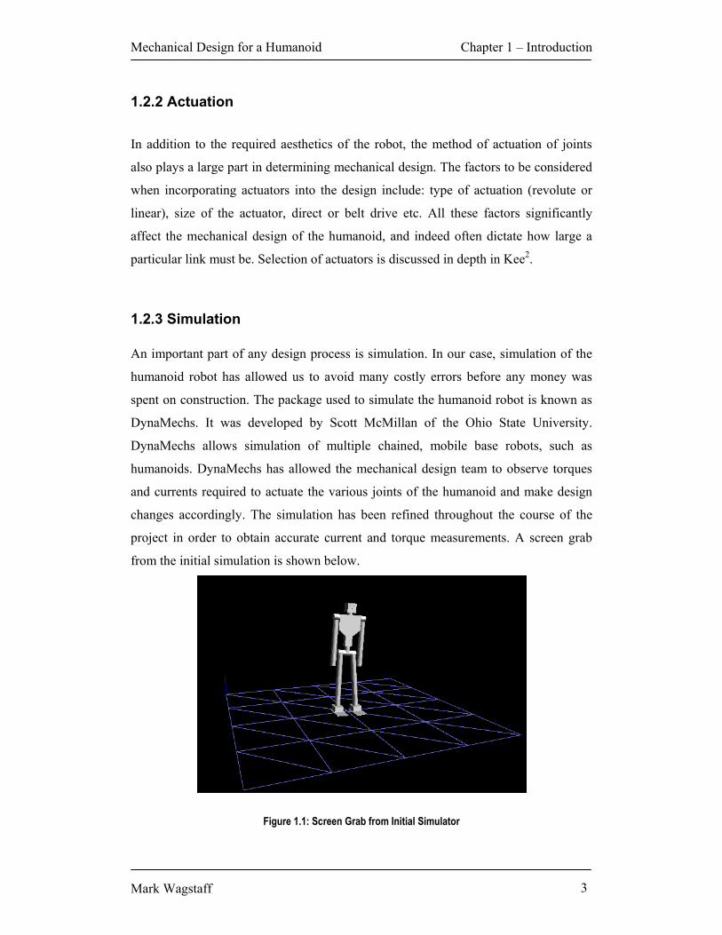
1.2.3 Simulation An important part of any design process is simulation. In our case, simulation of the
humanoid robot has allowed us to avoid many costly errors before any money was
spent on construction. The package used to simulate the humanoid robot is known as
DynaMechs. It was developed by Scott McMillan of the Ohio State University.
DynaMechs allows simulation of multiple chained, mobile base robots, such as
humanoids. DynaMechs has allowed the mechanical design team to observe torques
and currents required to actuate the various joints of the humanoid and make design
changes accordingly. The simulation has been refined throughout the course of the
project in order to obtain accurate current and torque measurements. A screen grab
from the initial simulation is shown below.
Figure 1.1: Screen Grab from Initial Simulator

Mechanical Design for a Humanoid Chapter 1 – Introduction
Mark Wagstaff 4
1.3 Statement of Achievements The initial goal of the project was to have a walking humanoid robot by August 2001.
This was a somewhat optimistic goal, and one that the team as a whole did not
achieve. The robot was to stand at 1.2m, weigh about 30kg and be able to walk at
0.1m/s.
The mechanical design of the robot is complete. A CAD solid model and technical
drawings for all parts required to build the robot are complete. At this time, these
parts are still being manufactured. Data gained from this model has been entered into
the simulator. A walking algorithm has been developed. The simulator has proven, in
theory at least, that the robot is able to walk. The current objective is to have a
working set of legs by demonstration day on 30 October 2001.
According to the CAD model, the robot will weigh approximately 38kg. It will stand
at 1.2m. The current simulator algorithm allows the robot to walk at about 0.03m/s.
1.4 Chapter Outline
The above results were achieved through careful design, including simulation. The
following chapters will detail exactly how the results were achieved.
Chapter two will discuss previous work in the field of humanoid robotics. This
includes discussion of human characteristics, as well as successful attempts made by
Sony and Honda.
Chapter three will outline broad specifications for the robot. This includes link
parameters and joint architecture. It will also briefly discuss the simulation of the
robot.

Mechanical Design for a Humanoid Chapter 1 – Introduction
Mark Wagstaff 5
Chapter four describes the design of the various links of the legs. Each section of the
chapter will include notable design features of components in that link.
Chapter five describes the design of the various links of the arms. Each section of the
chapter will include notable design features of components in that link.
Chapter six illustrates the design of the torso and neck. Special mention will be given
to the integration of components such as batteries, power board and iPAQ.
Information will also be presented on neck and head design.
Chapter seven will review results of the project to date and compare them to the
original objectives of the project.
Chapter eight will provide a summary of future work to be done on the robot. This
will include a discussion of sensor systems that may be added to the robot in order to
facilitate closed-loop walking.

Mechanical Design for a Humanoid Chapter 2 – Literature Review
Mark Wagstaff 6
Chapter 2 – Literature Review “AC motors? How about AC motors?” Damien Kee, June ’01 (While Asleep)
2.1 Initial Concept As previously mentioned, one of the main design criteria was ensuring that the robot
looked and moved like a human. In order to ensure this, a number of books describing
human locomotion were consulted. These were useful for determining link lengths,
desired centres of gravity of links, overall centre of gravity and required degrees of
freedom. Several robots, both active and passive, were studied before design
commenced. Many current bi-pedal robots have no torso, with studies concentrating
on the dynamics of the legs alone. Such robots include MIT’s M2, the Shadow Biped
(both active walkers) and McGeer’s passive dynamic walker. The best two current
examples of humanoid robots are ASIMO built by Honda and SDR-3X built by Sony.
2.2 Human Body Mechanics
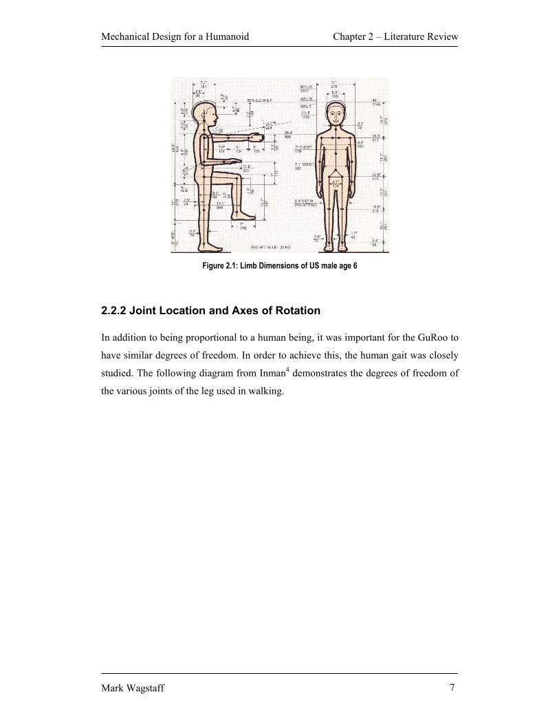
2.2.1 Link Lengths and Proportionality As has been previously alluded to, the mechanical design was based largely on the
human body. At the outset of the project, initial target specifications were decided
upon. Given initial estimates of the size of actuators available, as well as possible
future restrictions put in place by RoboCup rules, a target height of 1200mm was
decided upon. Using these parameters, the dimensions of the equivalent human were
able to be determined. These dimensions are based on those of a six year old, as
documented by Tilley 3 in the diagram below.
Mechanical Design for a Humanoid Chapter 2 – Literature Review
Mark Wagstaff 7
Figure 2.1: Limb Dimensions of US male age 6
2.2.2 Joint Location and Axes of Rotation In addition to being proportional to a human being, it was important for the GuRoo to
have similar degrees of freedom. In order to achieve this, the human gait was closely
studied. The following diagram from Inman4 demonstrates the degrees of freedom of
the various joints of the leg used in walking.

Mechanical Design for a Humanoid Chapter 2 – Literature Review
Mark Wagstaff 8
Figure 2.2: Leg joint rotations as seen in the sagittal, coronal and transverse planes.
Inman goes on to detail the involvement of the upper body in human walking.
Research by Sony5 and Honda6 has also revealed that it is important to utilise the
upper body to maintain balance while walking. In order to achieve human-like
movement, 3 degrees of freedom have been designed into the waist of the robot. This
greatly oversimplifies the spinal system of the human body, but provides enough
freedom for the robot to effectively use the upper body to help maintain balance. The
arms of the robot were also designed in such a way as to allow a contribution to the
overall balance of the robot. In addition to this, hands may later be added to increase
the currently very limited dexterity of the robot.
Mechanical Design for a Humanoid Chapter 2 – Literature Review
Mark Wagstaff 9
2.2.3 Mass parameters In order for the gait analyses performed on humans to be relevant to the GuRoo, it
was important for the mass distribution of the robot to resemble as closely as possible
that of humans. This allows research carried out by specialists in the medical field to
be applied to the walking algorithm of the robot.
2.3 Initial Simulation In order to roughly determine the torques required to actuate the various joints of the
robot, the parameters determined from research into the human body were entered
into the DynaMechs simulation software. “Computational Dynamics for Robotics
Systems on Land and Under Water” by McMillan7 was invaluable in developing a
simulation model. The DynaMechs simulation library8 provides descriptions of
various objects used within the DynaMechs simulator. It provided information on
creating a simulator model using Modified Denavit-Hartenberg (MDH) parameters9.
The simulation library also demonstrates how to define such values as joint limits and
motor parameters.
2.4 Actuation Given the figures generated by the initial simulation, the next step in the design
process was to find suitable actuators to motivate the joints of the robot. This is
discussed in more detail in Kee10, but will be briefly dealt with here. Several examples
of bipedal robots were analysed while determining the best way to actuate the robot.
2.4.1 Shadow Biped Robot The shadow biped robot11 utilises ‘air muscles’. Shadow claims that the air muscles
act like muscles on the human body12. The air muscles are very difficult to control,
but provide a good force/weight ratio. The overall construction of the shadow biped is
very crude, as can be seen below.

Mechanical Design for a Humanoid Chapter 2 – Literature Review
Mark Wagstaff 10
Figure 2.3: Shadow Biped
2.4.2 Honda ASIMO
Honda commenced work on its humanoid robot research and development program in
1986. The latest version of Honda’s humanoid, called ASIMO13, uses harmonic drives
to motivate the joints of the robot. These actuators, although providing a very good
torque/weight ratio, are extremely expensive. For this reason, harmonic drives were
not used on GuRoo.
Figure 2.4: Honda ASIMO

Mechanical Design for a Humanoid Chapter 2 – Literature Review
Mark Wagstaff 11
2.4.3 Sony SDR3X
Sony uses a newly developed actuator called “Actuato”, to motivate the joints of the
SDR-3X14. According to a Sony press release, Actuato is constructed from a motor
unit, a gear-unit and a circuit unit. Sony claims that Actuato provides high power from
a very lightweight package. Sony uses different size actuators depending on which
joint is being actuated. Specifications of the different actuators are shown below in
table 2.115.
Table 2.1: Properties of various “Actuato” actuators
Figure 2.5: Sony SDR-3X
Name ISA-S ISA-M ISA-MH Torque Rate (When 1A applied,kg.cm) 6.2 15.9 24.0 Size(mm) Ø 24 x 49.5 Ø 31 x 47.5 Ø 31 x 52.5 Mass(g) 73.5 119.7 143.2
Mechanical Design for a Humanoid Chapter 2 – Literature Review
Mark Wagstaff 12
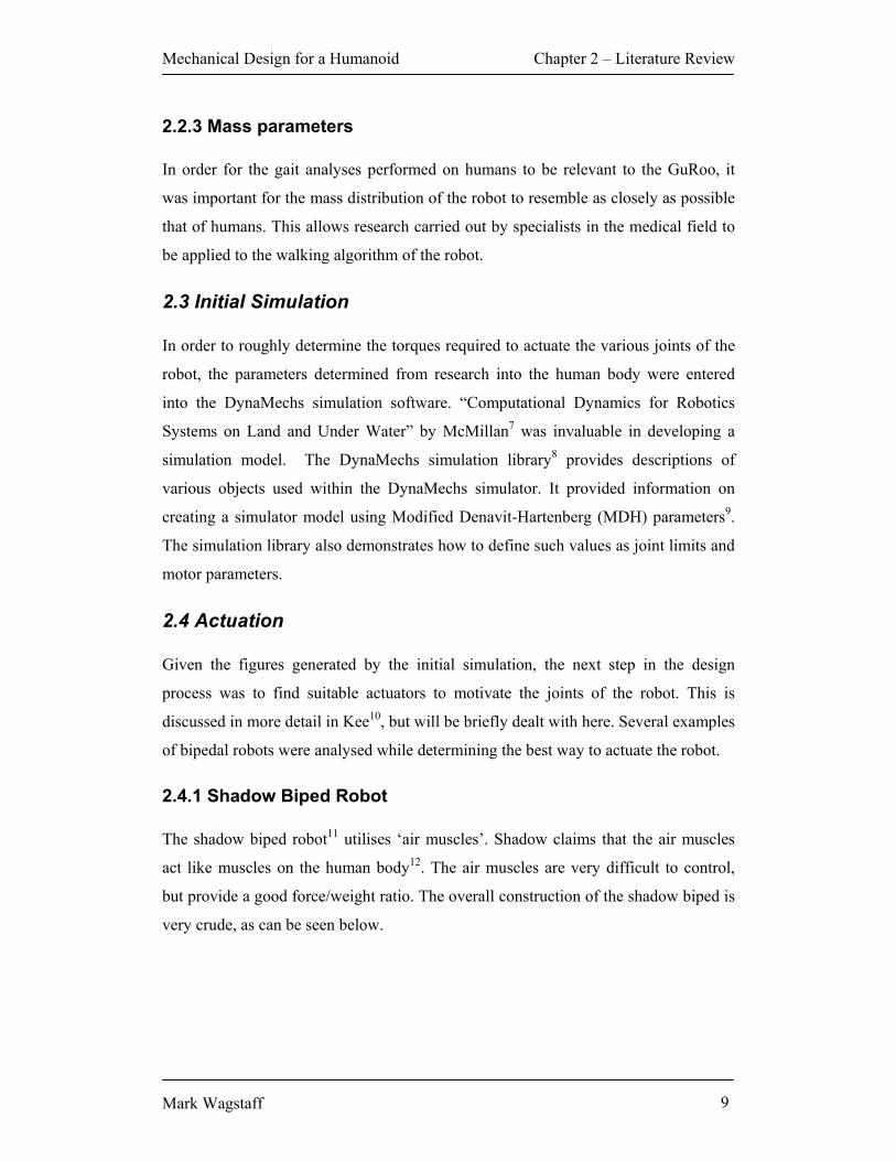
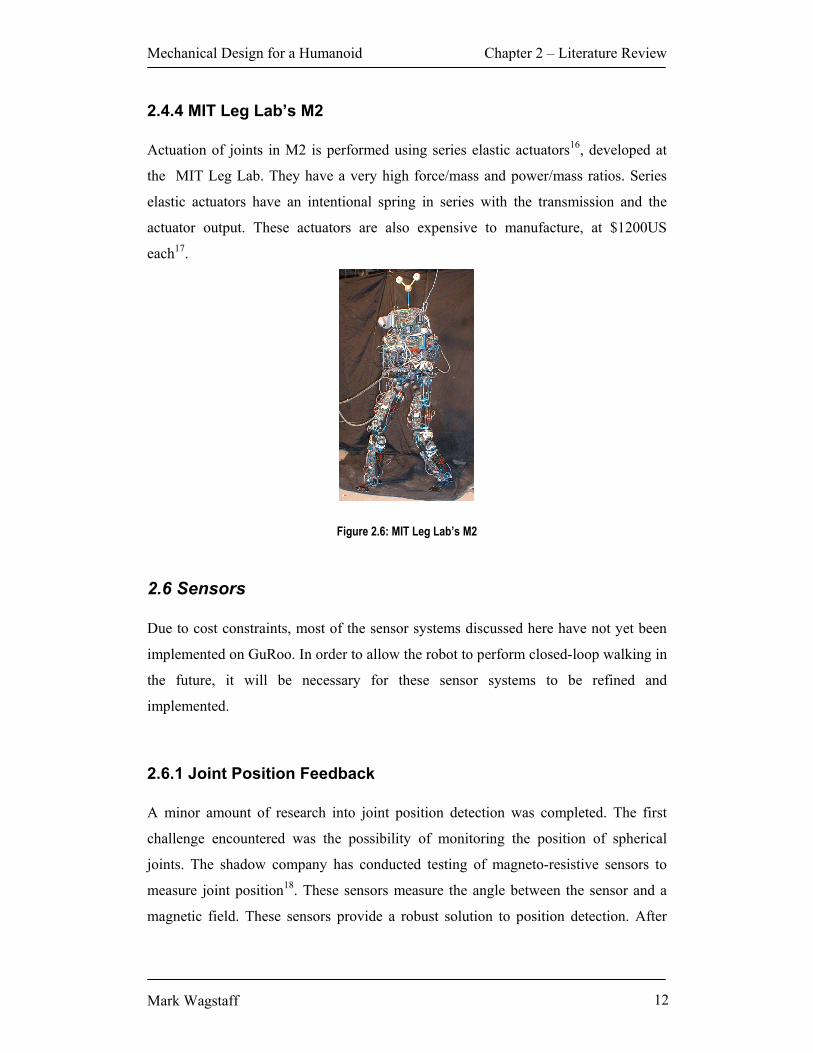
2.4.4 MIT Leg Lab’s M2 Actuation of joints in M2 is performed using series elastic actuators16, developed at
the MIT Leg Lab. They have a very high force/mass and power/mass ratios. Series
elastic actuators have an intentional spring in series with the transmission and the
actuator output. These actuators are also expensive to manufacture, at $1200US
each17.
Figure 2.6: MIT Leg Lab’s M2
2.6 Sensors Due to cost constraints, most of the sensor systems discussed here have not yet been
implemented on GuRoo. In order to allow the robot to perform closed-loop walking in
the future, it will be necessary for these sensor systems to be refined and
implemented.
2.6.1 Joint Position Feedback A minor amount of research into joint position detection was completed. The first
challenge encountered was the possibility of monitoring the position of spherical
joints. The shadow company has conducted testing of magneto-resistive sensors to
measure joint position18. These sensors measure the angle between the sensor and a
magnetic field. These sensors provide a robust solution to position detection. After

Mechanical Design for a Humanoid Chapter 2 – Literature Review
Mark Wagstaff 13
actuator selection, it became apparent that no spherical joints would be utilised in the
robot. As a result of this, no further research was conducted in this area.
Revolute DC motors are used in all joints of the GuRoo, apart from the arms. As a
result of this, joint position is determined using optical encoders. The optical encoders
utilised in the robot are supplied by the motor manufacturer, Maxon, as part of a
motor/encoder/gearbox package.
2.6.2 Balance As previously mentioned, in order for the GuRoo to perform open loop walking, some
form of balance feedback is necessary. Successful humanoid robots commonly have
three main groups of sensors: foot pressure/force, acceleration and angular rate
(gyroscope).
Honda’s ASIMO utilises six-axis force sensors in each foot of the robot.19 These
provide an indication of how much the robot is leaning to the side (roll), or leaning
forward or backward (pitch). In addition to this, ASIMO uses G-force and incline
detectors20 to measure the overall orientation of the robot.
Sony appears to use a similar arrangement in the SDR-3X. According to their press
release, the robot utilises a dual-axis accelerometer and dual-axis angular rate sensor
(gyroscope) to measure the orientation of the robot21.
M2 uses eight single axis load sensors (four per foot) on the bottom of the feet22,
performing a similar function to ASIMO’s foot sensors. These sensors are expensive,
at $450US each23. Rather than using a combination of gyroscopes and accelerometers,
an Intersense Inertia Cube TM is used to measure the roll, pitch and yaw of the robot
body24.

Mechanical Design for a Humanoid Chapter 3 – Design Process and Specification
Mark Wagstaff 14
Chapter 3 – Design Process and Specification “We’ll be cutting metal by the end of the month…” Mark Wagstaff 18 May ‘01
3.1 Design Process The design process of the GuRoo was, and indeed still is, an iterative one. Original
specifications were very broad, and hence allowed a lot of scope during the design
process. After research into human mechanics, it was possible to develop a very basic
software model of the robot. This simulation then allowed refinement of the
mechanical design, including selection of actuators. This in turn permitted further
refinement of the simulator, which resulted in a better mechanical model and so on.
The flowchart shown in figure 3.1 summarizes the design process.
Figure 3.1: Design Process Flowchart
3.1 Achieving Humanoid Aesthetics
3.1.1 Specification of Height and Weight
As has been mentioned in the previous chapters, one of the main design criteria for
the GuRoo was achieving a human-like appearance. In order to achieve this,
Research into human mechanics
Simulator Model
Actuator Selection / Proof of Concept
CAD Model
Technical Draw ings

Mechanical Design for a Humanoid Chapter 3 – Design Process and Specification
Mark Wagstaff 15
extremely broad specifications were initially defined. The robot needed legs, with
knees bending in the same direction as humans. The robot needed arms, with the
elbow bending in the same direction as humans. The robot needed a torso. Finally,
and perhaps most importantly (aesthetically speaking), the robot needed a head.
Given the broad specifications defined above, a target height and weight were
investigated. Several factors influenced the height and weight of the robot. These
were: previous attempts at humanoid robots, RoboCup rules, and budget.
As was mentioned in chapter two, there have been two previous impressive attempts
at building humanoid robots. These are Sony’s SDR-3X and Honda’s ASIMO. The
most striking difference between these robots is their respective heights and weights.
The SDR-3X stands at a short 500mm and weighs only 5kg. In stark contrast, ASIMO
stands at 1200m and weighs 43kg.
RoboCup rules placed limits on the dimensions of the robot. These rules may limit the
height of the robot to 1200mm. Specific rules for the humanoid competition were
released after design of the GuRoo25. These place restrictions on link lengths and
proportionality. Further clarification of these rules is being sought in order to ensure
that the GuRoo will conform.
The final limiting factor was project budget. The funding available limited the range
of actuators available. Kee26 discusses this in depth. Initial estimates of actuator size
were a 170mm long by 50mm radius cylinder for each actuator. Conservative
estimates put the mass of each actuator at 1kg each.
After consideration of these factors, a height of 1200mm and mass of 30kg were
specified.

Mechanical Design for a Humanoid Chapter 3 – Design Process and Specification
Mark Wagstaff 16
3.1.2 Specification of Link Parameters In order to maintain a human-like appearance, the various links of the robot had to be
in proportion to the human body. Knowledge gained from research into the human
form (see section 2.2) influenced specifications of link lengths. The dimensions
derived are shown below in figure 3.2.
Figure 3.2: Limb Dimensions of the GuRoo27
3.1.3 Joint Architecture For the GuRoo to move in a human fashion, the robot required a similar number of
degrees of freedom as a human. The robot has 23 degrees of freedom. The location of
each degree of freedom is shown in figure 3.3.

Mechanical Design for a Humanoid Chapter 3 – Design Process and Specification
Mark Wagstaff 17
Figure 3.3 Degrees of Freedom of the GuRoo
It is important to note that joints, especially the hip and spine, are not implemented in
the same way as they are in the human body. Later sections of this thesis will detail
the reasons behind this. Suffice to say at this point that the spine of the GuRoo is
nowhere near as complex as a human spine, and spherical joints, such as the hip, are
implemented as a series of revolute actuators, rather than a single spherical joint.
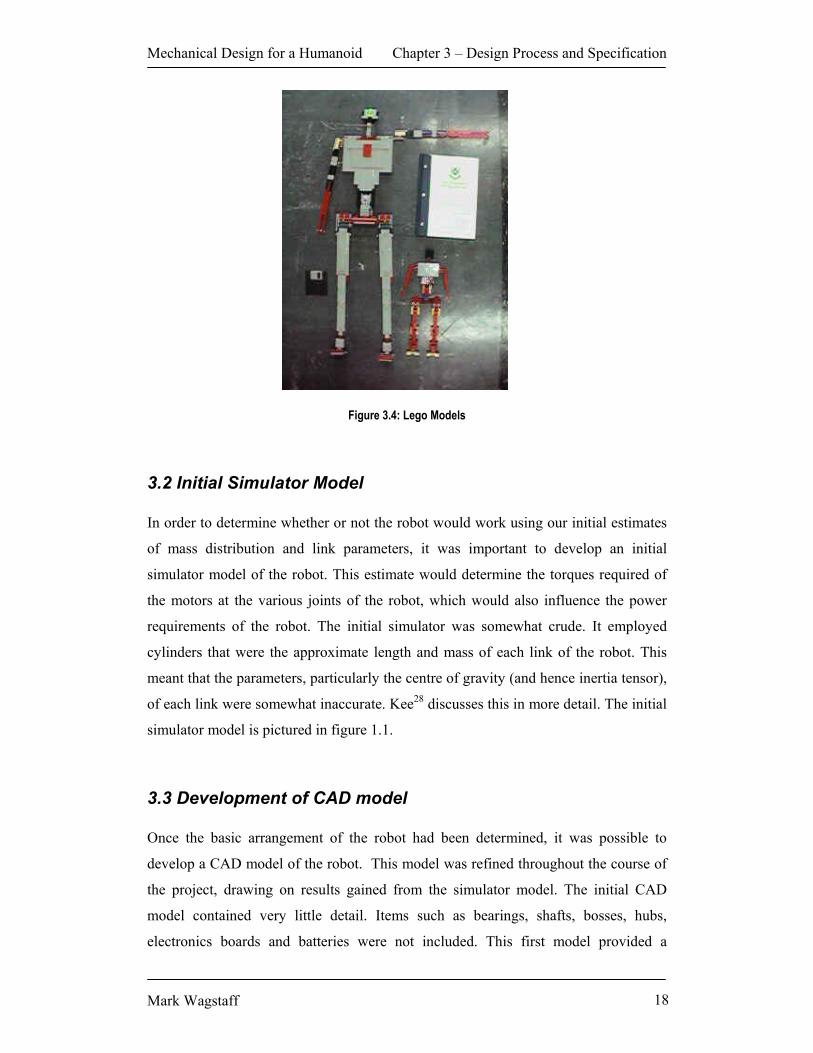
In order to provide a reference to the required degrees of freedom during the
mechanical design, a pair of Lego models was constructed. The first, known as “mini-
dude”, was a miniaturised version of the GuRoo. The second, known as just “the
dude”, was a full-scale model of the GuRoo. Both models had the same number of
degrees of freedom as the real GuRoo. The series of revolute actuators used to imitate
spherical joints were modelled in the same order as they would be placed on the robot.
Due to the use of revolute actuators, the upper leg of the robot (one limb on a human)
is constructed of three separate links. The Lego model allowed the mechanical team to
estimate the dimensions of each particular link (eg. Flexion, abduction, rotation),
rather than nominating just “upper leg length”.
Mechanical Design for a Humanoid Chapter 3 – Design Process and Specification
Mark Wagstaff 18
Figure 3.4: Lego Models
3.2 Initial Simulator Model In order to determine whether or not the robot would work using our initial estimates
of mass distribution and link parameters, it was important to develop an initial
simulator model of the robot. This estimate would determine the torques required of
the motors at the various joints of the robot, which would also influence the power
requirements of the robot. The initial simulator was somewhat crude. It employed
cylinders that were the approximate length and mass of each link of the robot. This
meant that the parameters, particularly the centre of gravity (and hence inertia tensor),
of each link were somewhat inaccurate. Kee28 discusses this in more detail. The initial
simulator model is pictured in figure 1.1.
3.3 Development of CAD model Once the basic arrangement of the robot had been determined, it was possible to
develop a CAD model of the robot. This model was refined throughout the course of
the project, drawing on results gained from the simulator model. The initial CAD
model contained very little detail. Items such as bearings, shafts, bosses, hubs,
electronics boards and batteries were not included. This first model provided a

Mechanical Design for a Humanoid Chapter 3 – Design Process and Specification
Mark Wagstaff 19
concept model of the robot. This concept model was gradually developed into the
final robot. The vast difference in each can been seen in the figure below.
(a) (b)
Figure 3.5 (a) First complete CAD model, August 01 (b) CAD model as at 05 October 01

Mechanical Design for a Humanoid Chapter 4 – Leg Design
Mark Wagstaff 20
Chapter 4 – Leg Design “The dude will walk.” Andrew Smith May ‘01
4.1 Overview
Perhaps the most important part of the robot is the legs. Without sufficient leg
strength, the robot will surely not walk. The legs require six degrees of freedom each
in order to achieve a satisfactory gait. All framework for the legs is constructed from
6061-T6 aluminium. This material was chosen for its rigidity, low weight and ease of
machining. The main disadvantage of this particular alloy is that it is difficult to bend
and weld. This resulted in some manufacturing difficulties (see section 7.2). Figure
7.1 shows a view of the leg assembly.
Figure 4.1: Leg Assembly
Mechanical Design for a Humanoid Chapter 4 – Leg Design
Mark Wagstaff 21
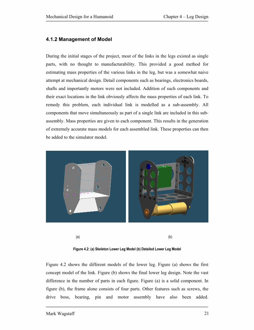
4.1.2 Management of Model
During the initial stages of the project, most of the links in the legs existed as single
parts, with no thought to manufacturability. This provided a good method for
estimating mass properties of the various links in the leg, but was a somewhat naive
attempt at mechanical design. Detail components such as bearings, electronics boards,
shafts and importantly motors were not included. Addition of such components and
their exact locations in the link obviously affects the mass properties of each link. To
remedy this problem, each individual link is modelled as a sub-assembly. All
components that move simultaneously as part of a single link are included in this sub-
assembly. Mass properties are given to each component. This results in the generation
of extremely accurate mass models for each assembled link. These properties can then
be added to the simulator model.
(a) (b)
Figure 4.2: (a) Skeleton Lower Leg Model (b) Detailed Lower Leg Model
Figure 4.2 shows the different models of the lower leg. Figure (a) shows the first
concept model of the link. Figure (b) shows the final lower leg design. Note the vast
difference in the number of parts in each figure. Figure (a) is a solid component. In
figure (b), the frame alone consists of four parts. Other features such as screws, the
drive boss, bearing, pin and motor assembly have also been added.

Mechanical Design for a Humanoid Chapter 4 – Leg Design
Mark Wagstaff 22
4.2 Common Parts
As has been previously mentioned, the leg is made up of several links, each
constructed as a separate sub-assembly. Some parts are common to each sub-assembly
and will be discussed here.
4.2.1 Actuator All actuators in the legs of the robot are revolute actuators in the form of DC motors
driving through a gearbox. Maxon RE36 series DC motors driving through a 156:1
GP 42 series 4-stage gearbox are used to motivate all joints in the legs. This
combination is capable of providing 19Nm of torque. Position feedback for these
motors is provided by the standard Maxon HEDS 55 digital encoder. Actuator
selection is dealt with in detail in Kee29. The motor assembly contains three main
components:
1. Encoder
2. Motor
3. Gearbox
The motor, encoder and gearbox are supplied assembled. Dimensions for the
assembly are supplied in the data sheet attached as appendix 2. The motor is flange
mounted. It is fastened using 4 x M4 countersunk flat head socket screws. The shaft
has a diameter of 12mm. Torque is transmitted through a parallel key, manufactured
to DIN 6885A.

Mechanical Design for a Humanoid Chapter 4 – Leg Design
Mark Wagstaff 23
Figure 4.3: Motor Assembly
4.2.2 Boss The boss is used to transmit torque from the GP 42 gearhead to the next link in the
robot. The boss consists of two parts: the boss itself and the end cap. The boss is
attached to the appropriate link by 4 x M4 Socket Head screws. The bore in the shaft
is 12mm in diameter to suit the GP 42 series gearhead. Torque is transmitted through
the key on the motor shaft. The keyway cut into the boss suits an A4 x 4 key
manufactured to DIN 6885A, as found in the GP 42 gearhead. As can be seen in the
solid model below, the boss has a flange. This flange is used to locate the boss in the
link. (As opposed to using screws to locate the boss.)
The end-cap butts against the end of the motor shaft. This, in conjunction with the
lazy-end shaft, is used to locate the link in the coronal plane. The end cap is attached
to the boss by two M3 button-head screws.

Mechanical Design for a Humanoid Chapter 4 – Leg Design
Mark Wagstaff 24
Figure 4.4: Boss
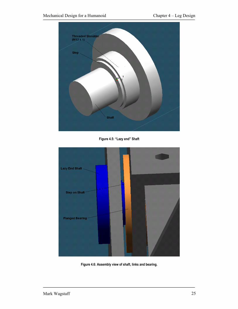
4.2.3 Lazy-end shaft As its name suggests, this shaft supports the lazy end of the joint (the side not
transmitting torque). The shaft screws into the link. The step abuts the inner ring of
the lazy end bearing of the link above. This is demonstrated in figure 4.6. This, in
conjunction with the end cap of the boss assembly, locates the link in the coronal
plane. The shaft has been designed in order to withstand shear stress placed on it by
the weight and walking motion of the robot.
Mechanical Design for a Humanoid Chapter 4 – Leg Design
Mark Wagstaff 25
Figure 4.5: “Lazy end” Shaft
Figure 4.6: Assembly view of shaft, links and bearing.

Mechanical Design for a Humanoid Chapter 4 – Leg Design
Mark Wagstaff 26
4.2.4 Lazy-end bearing The lazy end bearing is an NMB radial flanged ball bearing. Its radial load bearing
capacity is 337kg (dynamic) and 140kg (static). It allows low friction movement of
the lazy end of each joint. The flange prevents movement of the bearing in the coronal
plane.
4.3 Foot
Although perhaps one of the most important parts of the robot, the foot is somewhat
underdeveloped. Possible improvements to the foot are discussed in chapter 8. It
currently contains four parts (See figure 4.7):
1. The boss assembly,
2. the foot itself,
3. the ankle shaft support bracket, and
4. a radial bearing.
Figure 4.7: Foot Assembly

Mechanical Design for a Humanoid Chapter 4 – Leg Design
Mark Wagstaff 27
In order to save weight, a plastic bush will replace the bearing in the near future. The
boss transmits torque from the motor mounted in the ankle to the foot, providing one
degree of freedom of ankle rotation. The shaft from the ankle fits into the bearing,
providing the lazy end of the arrangement. The inner diameter of the shaft is larger
than the outer diameter of the motor assembly, ensuring that no load is beared by the
motor. This can be seen in figure 4.8.
Figure 4.8: Ankle Shaft – Foot interface
Currently the only sensors intended for the foot in the short term are four force
sensors, located near each corner of the foot, to identify that a particular part of the
foot has made contact with the ground. It is anticipated that a “smarter” foot will be
added in the future. It will be possible to bolt the “smart foot” to the bottom of the
current design. This “smart foot” will probably include some sort of analogue force
sensing to measure weight distribution over the foot. This will greatly enhance the
robot’s capacity to perform closed-loop walking. It may also be possible to add some
compliancy to the foot. This may include a flexible arch and sprung toe. Future work
on the foot is discussed in more detail in chapter 8.

Mechanical Design for a Humanoid Chapter 4 – Leg Design
Mark Wagstaff 28
4.4 Ankle
The ankle provides one degree of freedom in the ankle joint. The frame of the ankle
contains three main parts. These are:
1. The Ankle itself,
2. ankle bracket, and
3. ankle shaft.
These parts can be seen in figure 4.9 below. In addition to these, the ankle assembly
contains the lazy-end pin, boss and motor assembly.
Figure 4.9: Ankle Assembly
The ankle shaft, along with the motor shaft, bears the weight of the robot. The ankle
shaft is designed to fit around the motor. This allows the motor to be mounted along
the length of the foot. The location of this shaft is important in the design of the robot.
In the initial design stage, the shaft was central to the ankle. This is shown in figure
4.10.

Mechanical Design for a Humanoid Chapter 4 – Leg Design
Mark Wagstaff 29
Figure 4.10: Old Ankle Location
Simulation showed that the torque required of this joint was excessive. Two options
were considered. The first was to increase the torque available from the actuator. This
would mean a larger, more powerful motor and gearbox. The result would entail
increased cost and would put excessive current requirements on the electrical system.
The second option was to decrease the moment arm acting on the joint. This can be
achieved through two means: decrease the force acting on the joint or decrease the
distance at which this force is acting. The force acting on the joint could be reduced in
two ways: firstly decrease the overall mass of the robot and secondly, use the weight
of the robot to counterbalance itself. The distance at which the force is acting can be
decreased by moving the point of rotation closer to the centre of mass of the robot.
Both the above facts suggested that it would be wise to relocate the ankle joint closer
to the centreline of the robot. The revised ankle position can be seen in figure 4.11.
Simulation showed that this greatly reduced the torque requirements placed on the
actuators in the ankle.

Mechanical Design for a Humanoid Chapter 4 – Leg Design
Mark Wagstaff 30
Figure 4.11: Revised Ankle Location
4.5 Lower Leg
The lower leg is analogous to the shin of the robot. It provides the second degree of
freedom for the ankle of the robot. The frame consists of four main parts:
1. Inner Side Bracket
2. Outer Side Bracket
3. Cross-Piece Assembly
4. PCB Mounting Panel Assembly
All of the above components are milled in order to save weight. The mass of each
component has been reduced by 50 to 75 per cent. The cross-piece and PCB mounting
panel provide torsional rigidity to the joint. Both these components are manufactured
to a high level of precision, as they dictate the width of the link.

Mechanical Design for a Humanoid Chapter 4 – Leg Design
Mark Wagstaff 31
Figure 4.12: Lower Leg Assembly
The manufacture of the cross-piece and PCB mounting panel was a source of great
inconvenience. In an ideal situation, standard channel would be used to manufacture
these parts. Due to the size of the actuators, it was not possible to source channel of
sufficient width to manufacture the components. It was suggested by the workshop
that the components be welded, essentially achieving the same solution as extruded
channel (though a somewhat more labour-intensive method). (See figure 4.13). This
proved to be ineffective, as it was found that the 6061-T6 aluminium used in the
construction of the components deformed by as much as 0.7mm upon being welded.
This left two possible options: folding, or incorporating extruded angle. Workshop
staff advised that the required precision could not be achieved by folding. It was
decided that extruded aluminium angle would be used to construct the parts (See
figure 4.14). This resulted in extremely precise components, at a small cost in weight.
The angle is riveted and bonded to each panel. Note the positioning of the angle in
relation to the mounting panel. This design ensures that any shear force is transferred
through the angle and is not borne by the rivets. The design also ensures accurate
placement of the angle.

Mechanical Design for a Humanoid Chapter 4 – Leg Design
Mark Wagstaff 32
Figure 4.13: Original Panel Design (Welded)
Figure 4.14: Revised Panel Design (Angle)

Mechanical Design for a Humanoid Chapter 4 – Leg Design
Mark Wagstaff 33
Each panel is fastened to the side brackets by 4 x M4 socket screws. These are
strengthened using Loctite Threadlocker 222.
The controller board shown in figure 4.12 is used to control the lower three links of
the robot, i.e. the foot, the ankle and the lower leg. The board is located to achieve the
shortest distance possible between the controller and the actuators it controls. This
reduces the chance of noise interference damaging the communications signal
between the motor and controller. The board is positioned to allow connection of
components that require heat sinking to the mounting panel.
4.6 Upper Leg - Yaw
This link provides yaw for the hip joint. This is one of three degrees of freedom
available in the hips. The link also includes the actuator responsible for motivating the
knee joint of the robot. The major components of this link are:
1. Outer bracket,
2. Inner Bracket,
3. PCB Mounting Panel,
4. Thrust Bearing, and
5. Mounting Spigot for Thrust Bearing.
Once again, the inner and outer brackets were to be welded. It is anticipated that these
parts will suffer the same problems as the lower leg and will be modified for
construction using extruded angle (see section 4.5). Both these brackets are milled
significantly in order to save weight. The PCB used to control the three degrees of
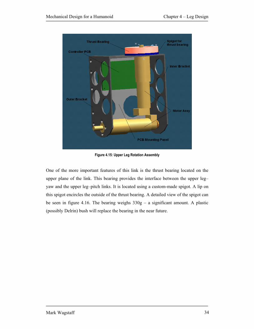
freedom of the hip is mounted in this link and can be seen in figure 4.15.
Mechanical Design for a Humanoid Chapter 4 – Leg Design
Mark Wagstaff 34
Figure 4.15: Upper Leg Rotation Assembly
One of the more important features of this link is the thrust bearing located on the
upper plane of the link. This bearing provides the interface between the upper leg–
yaw and the upper leg–pitch links. It is located using a custom-made spigot. A lip on
this spigot encircles the outside of the thrust bearing. A detailed view of the spigot can
be seen in figure 4.16. The bearing weighs 330g – a significant amount. A plastic
(possibly Delrin) bush will replace the bearing in the near future.

Mechanical Design for a Humanoid Chapter 4 – Leg Design
Mark Wagstaff 35
Figure 4.16: Spigot for Thrust Bearing
4.7 Upper Leg – Flexion
This link contains no actuators. The main features of note in this link are the Fenner
taper lock bush and weld-on hub. These are used to fasten the motor shaft from the
rotation link described in section 4.6. The taper lock bush and weld-on hub can be
seen in figure 4.17. A taper lock bush was chosen for its excellent ability to grip the
motor shaft. This bush is required to resist shear due to the weight of the leg below the
flexion link. It is connected to the flexion link by a weld-on hub. The hub is a
convenient means of interfacing the bush to the link itself. The disadvantage of the
hub is its weight. The hub is made of steel and weighs approximately 600g. Currently,
the replacement of this hub with a custom-made aluminium equivalent is being
investigated. The replacement of the hub should result in a weight saving of about 75
per cent. This equates to a saving of 450g on each leg – a significant amount.

Mechanical Design for a Humanoid Chapter 4 – Leg Design
Mark Wagstaff 36
Figure 4.17: Flexion Assembly
4.8 Upper Leg – Abduction The abduction link of the GuRoo provides actuation for the second degree of freedom
of the hip joint. All components in the abduction link are manufactured from standard
plate and extruded angle. The most easily overlooked component of the abduction
link is the mounting spigot for the torsion spring found in the hip of the robot. This
spring will be discussed further in section 4.9. The spigot has been positioned 5° off
vertical. This will ensure that the legs of the robot hang vertical under their own
weight. As can be seen in figure 4.18, the hip attachment point on the link is not
central to the joint. This is an important design feature and will be discussed further in
section 4.9.

Mechanical Design for a Humanoid Chapter 4 – Leg Design
Mark Wagstaff 37
Figure 4.18: Abduction Assembly
4.9 Hip Assembly The hip assembly contains the actuators for the first degree of freedom of the hip of
the robot. These actuators are assisted by a torsion spring. The hip also houses the
controller board responsible for controlling the 3 degrees of freedom in the spine of
the robot. The actuator responsible for motivating the first degree of freedom of the
spine is also housed in this link. A view of the underside of the hip can be seen below
in figure 4.19.

Mechanical Design for a Humanoid Chapter 4 – Leg Design
Mark Wagstaff 38
Figure 4.19: View of hip joint from underneath.
There are several design features in the hip joint worth mention. The first is the
distance between axes of revolution of the abduction joints. A comparison can be seen
in figure 4.20. In figure 4.20(a), the axes of rotation of the abduction joints are
105mm from the central axis of the robot. In figure 4.20(b), the axes of rotation of are
only 75mm from the central axis of the robot. This achieves two objectives. Firstly,
this ensures that the axis of rotation is in line with the yaw axis of the hip and the roll
axis of the ankle. This simplifies the Denavit-Hartenberg parameters used in the
simulator, hence simplifying the walking algorithm. Secondly, and more importantly,
the moment arms acting on the actuators in this joint are greatly reduced. Further
simulation conducted by Smith confirmed this.30

Mechanical Design for a Humanoid Chapter 4 – Leg Design
Mark Wagstaff 39
(a) (b)
Figure 4.20: (a) Hip design August 2001 (b) Hip design October 2001
Simulation showed that despite the improvement in torque requirements gained by
relocating the axes of rotation, the loads on the motors on this joint were still
unacceptably high. It was evident that a method of storing energy in the hip joint was
required.
The most obvious solution to this problem was some sort of spring arrangement. The
favoured solution was a torsion spring placed in parallel with the actuator. The spring
is shown in figure 4.19. The spring constant of the torsion spring is 1Nm per degree.
Detailed calculations regarding the selection of the spring are found in Kee31. The
spring is mounted on a shaft which encapsulates the motor assembly. It is held in
place by the torsion spring spigot shown in figure 4.18 and the locator hole in the
mounting bracket shown in figure 4.21.

Mechanical Design for a Humanoid Chapter 4 – Leg Design
Mark Wagstaff 40
Figure 4.21: Torsion Spring Mounting Arrangement

Mechanical Design for a Humanoid Chapter 5 – Arm Design
Mark Wagstaff 41
Chapter 5 – Arm Design “He needs a hook… like Captain Hook.” Andrew Blower May ‘01
5.1 Overview The arms of the GuRoo are utilised mainly for aesthetic purposes. This is due to the
current walking algorithm being static, rather than dynamic (see Smith32 for further
information). All joints in the arms are actuated by Hi-Tech DC Servo-motors. These
motors are capable of providing 1.3Nm of torque. All links are constructed from
standard aluminium box, which greatly reduces manufacturing time. The arm has
three degrees of freedom: two in the shoulder, one in the elbow. This is evident in
figure 3.2. It consists of two links: the upper and lower arm. These can be seen below
in figure 5.1.
Figure 5.1: Arm Assembly

Mechanical Design for a Humanoid Chapter 5 – Arm Design
Mark Wagstaff 42
5.2 Shoulder and Upper Arm The shoulder provides two degrees of freedom to the arm. The first servo motor is
mounted in the torso as shown in figure 5.2. The limit-plate shown in figure 5.2
restricts the range of motion of the upper arm. This prevents damage to the servo
motor due to over-rotation caused by accident (falling, dropping etc.)
Figure 5.2: Location of servo motor for shoulder
The shoulder joint contains the servo motor used to actuate the second degree of
freedom of the arm. The servo is connected to the upper arm with the standard horn
provided with the servo motor. The lazy end of the joint is connected to the upper arm
in a similar fashion to the lazy end of the leg joints. The shoulder assembly is shown
in figure 5.3.
The upper arm is fashioned from standard aluminium box section. This is milled out
to save weight. The servo motor which motivates the elbow joint is fastened in a
bracket identical to that used in the shoulder joint. This bracket is welded to the upper
arm. The upper arm assembly is shown in figure 5.4

Mechanical Design for a Humanoid Chapter 5 – Arm Design
Mark Wagstaff 43
Figure 5.3: Shoulder Assembly
Figure 5.4: Upper Arm Assembly

Mechanical Design for a Humanoid Chapter 5 – Arm Design
Mark Wagstaff 44
5.3 Lower Arm
The lower arm is also fashioned from standard aluminium box section. This is milled
out to save weight. The only other notable feature is the lazy-end pin used to locate
the link on the elbow joint.
Figure 5.5: Lower Arm Assembly

Mechanical Design for a Humanoid Chapter 6 – Upper Body
Mark Wagstaff 45
Chapter 6 – Upper Body “I’ve got a better upper body than you.” Damien Kee June ‘01
6.1 Overview The upper body performs several functions. Firstly, the spine of the robot has three
degrees of freedom. This is obviously far less complex than a human spine, but
provides enough range of motion to utilise the torso as a counterbalance using
walking. Secondly, the torso houses several important components of the robot. These
are the power system, including batteries, and the iPAQ and associated circuitry. The
neck is also mounted on the torso. The torso assembly can be seen below:
Figure 6.1: Rear view of torso assembly

Mechanical Design for a Humanoid Chapter 6 – Upper Body
Mark Wagstaff 46
6.2 Torso As previously mentioned, the torso houses several important components of the
system:
• 4 x Battery
• Power Board
• Servo Controller Board
• Vision Board
• iPAQ to Vision Conversion Board
• iPAQ
In addition to this, the torso provides mounting locations for the head and shoulder
actuators, as well as the yaw degree of freedom of the spine. The major challenge in
designing the torso was housing such a large number of components while
maintaining the correct proportions. Unavoidably, the torso is somewhat thickset,
giving the GuRoo a somewhat stocky appearance when viewed side-on.
Figure 6.2: Side on view of GuRoo
The torso underwent a significant design change partway through the project in order
to facilitate better integration of the yaw joint of the spine. Figures 6.3 and 6.4 depict
the original and current torso designs respectively.
There are several important differences between each design. The first and perhaps
most noticeable, is the method of mounting the yaw link of the spine. In the original
design, seen in figure 6.3, a box extended from the base of the torso. The manufacture
of this component would have been time consuming. The box would also be heavy

Mechanical Design for a Humanoid Chapter 6 – Upper Body
Mark Wagstaff 47
and it occupied a large amount of space in the torso. A better solution was required.
The box was removed from the torso and was replaced by a shelf. This is evident in
figure 6.4. The shelf occupies much less space than the box. In addition to this it adds
rigidity to the torso. It also provides a location for mounting the batteries seen in
figure 6.1. The shelf allows easy placement of a weld on hub, which is used to
connect the yaw joint of the spine. This will be discussed in more detail in section 6.3.
In the newer torso design, physical stops have been included. These limit the range of
motion of the arms of the robot, as discussed in chapter 5. A mounting location for the
iPAQ and associated boards has been provided. This will allow access to the iPAQ, as
well the ability to view the screen. The iPAQ will be mounted so that its face lies
behind the plane of the torso assembly, protecting it from accidental damage. Much of
the lower portion of the torso is milled away to allow weight saving.
Figure 6.3: Torso as at May 2001

Mechanical Design for a Humanoid Chapter 6 – Upper Body
Mark Wagstaff 48
Figure 6.4: Torso as at 15 Oct 2001
6.3 Spine
The spine has three degrees of freedom: pitch, roll and yaw. The same Maxon DC
motor that is used in the legs of the robot actuates all joints in the spine. Figure 6.5
shows an assembled view of the spine.
6.3.1 Pitch Pitch is the first degree of freedom in the spine. It consists of two brackets, mounted
on the hip. The lazy end of the joint is fastened in the same manner as those in the
legs (see section 4.2.3). The assembly can be seen in figure 6.6.
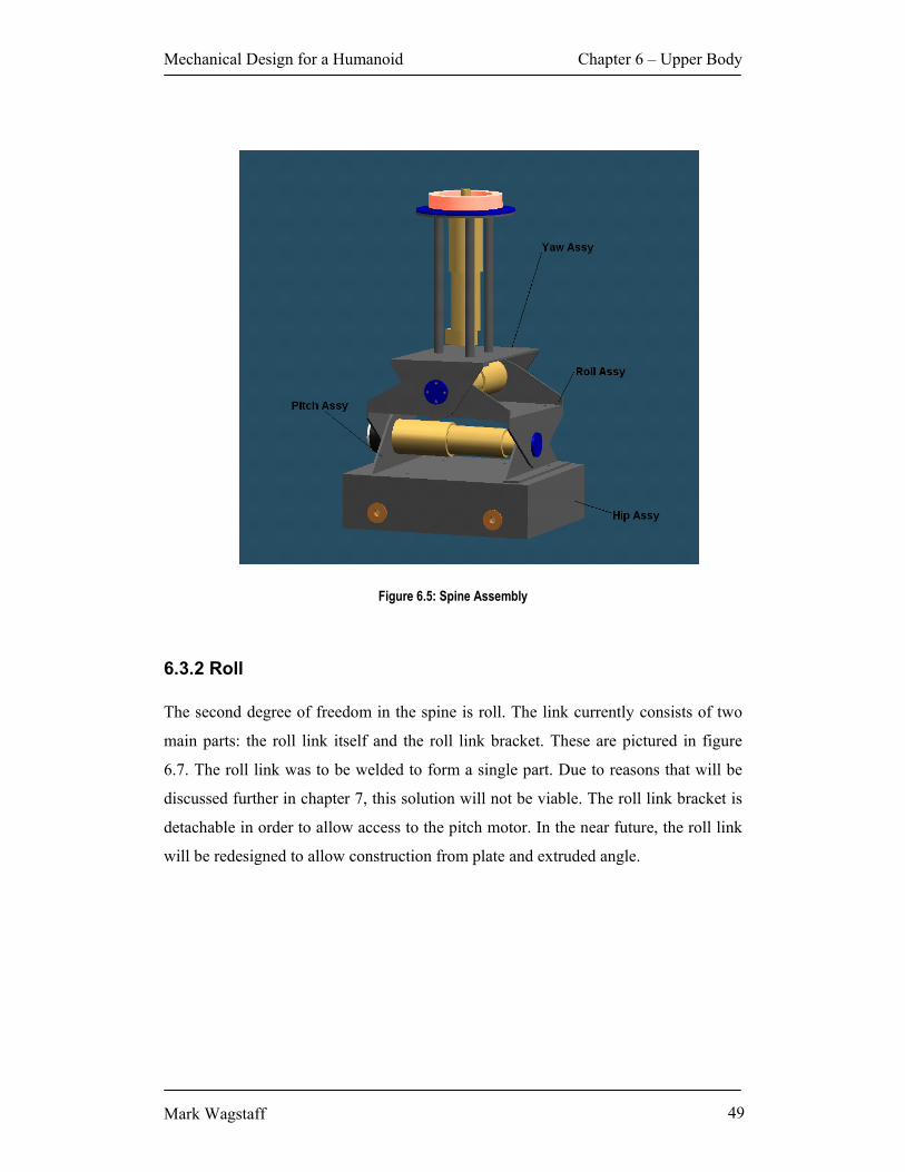
Mechanical Design for a Humanoid Chapter 6 – Upper Body
Mark Wagstaff 49
Figure 6.5: Spine Assembly
6.3.2 Roll The second degree of freedom in the spine is roll. The link currently consists of two
main parts: the roll link itself and the roll link bracket. These are pictured in figure
6.7. The roll link was to be welded to form a single part. Due to reasons that will be
discussed further in chapter 7, this solution will not be viable. The roll link bracket is
detachable in order to allow access to the pitch motor. In the near future, the roll link
will be redesigned to allow construction from plate and extruded angle.
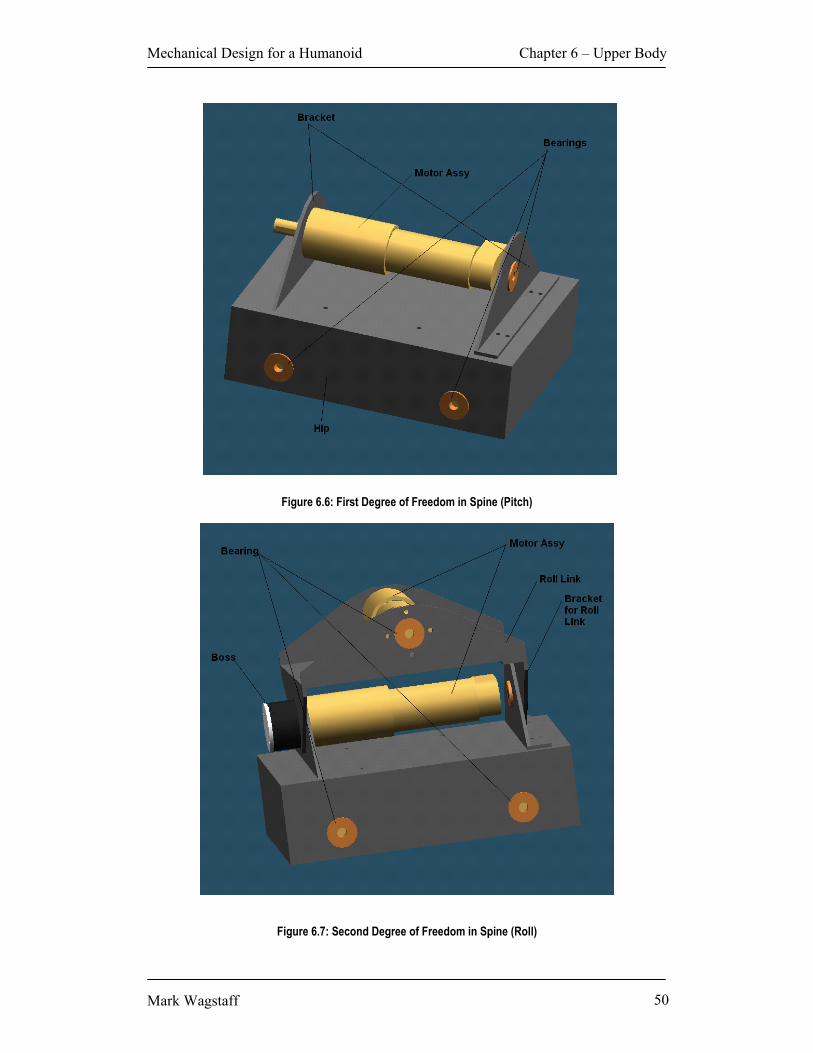
Mechanical Design for a Humanoid Chapter 6 – Upper Body
Mark Wagstaff 50
Figure 6.6: First Degree of Freedom in Spine (Pitch)
Figure 6.7: Second Degree of Freedom in Spine (Roll)

Mechanical Design for a Humanoid Chapter 6 – Upper Body
Mark Wagstaff 51
6.3.3 Yaw Yaw is the final link of the spine. It posed more design challenges than most links of
the robot. The final solution is the most aesthetically pleasing and mechanically
efficient design considered. The link underwent significant refinement during the
project. The first design can be seen in figure 6.8.
Figure 6.8: Original Spine Yaw Link May 2001
Figure 6.9 depicts the link assembly as it exists at October 2001. In figure 6.9 it can
be seen that the mounting location for the motor has been changed significantly. The
two-sided rectangular mechanism shown in figure 6.8 has been replaced by a more
structurally sound cage. The cage consists of three standard 7075 aluminium rods
separated by 120°. This cage also occupies less space than the original design. Several
detail features have also been added. The most important of these is the thrust bearing
and spigot. These provide an interface between the link and the torso. The motor shaft
is attached to the torso assembly by a taper lock bush and weld on hub, identical to
those used in the legs. This will be replaced by a custom bush and hub in the near
future (see section 4.7 for more detail). This interface is depicted in figure 6.9. The
yaw joint can be seen assembled with the torso in figure 6.10.

Mechanical Design for a Humanoid Chapter 6 – Upper Body
Mark Wagstaff 52
Figure 6.9: Spine Yaw Assembly
Figure 6.10: Spine and Torso Assembly

Mechanical Design for a Humanoid Chapter 6 – Upper Body
Mark Wagstaff 53
6.4 Neck and Head
The neck is required to provide two degrees of freedom: pan and tilt. Two Hi-tech
servo motors actuate the joints in the neck. These motors are the same as those used to
actuate the arms.33 The motor used to actuate the pan motion is mounted in the torso.
Its location can be seen in figure 6.4 The bracket used to house the tilt motor is the
same as that used to house the motors in the arms of the robot (see section 5.2). This
again saves design and manufacture time.
The head houses the vision system of the robot. The design of the head was
influenced by the size and shape of the camera, as well as aesthetic factors. A detailed
description of the head design can be found in Blower34. The neck and head assembly
can be seen below in figure 6.11.
Figure 6.11: Head Assembly
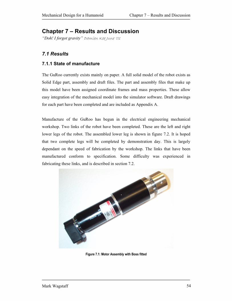
Mechanical Design for a Humanoid Chapter 7 – Results and Discussion
Mark Wagstaff 54
Chapter 7 – Results and Discussion “Doh! I forgot gravity” Damien Kee June ‘01
7.1 Results
7.1.1 State of manufacture The GuRoo currently exists mainly on paper. A full solid model of the robot exists as
Solid Edge part, assembly and draft files. The part and assembly files that make up
this model have been assigned coordinate frames and mass properties. These allow
easy integration of the mechanical model into the simulator software. Draft drawings
for each part have been completed and are included as Appendix A.
Manufacture of the GuRoo has begun in the electrical engineering mechanical
workshop. Two links of the robot have been completed. These are the left and right
lower legs of the robot. The assembled lower leg is shown in figure 7.2. It is hoped
that two complete legs will be completed by demonstration day. This is largely
dependant on the speed of fabrication by the workshop. The links that have been
manufactured conform to specification. Some difficulty was experienced in
fabricating these links, and is described in section 7.2.
Figure 7.1: Motor Assembly with Boss fitted

Mechanical Design for a Humanoid Chapter 7 – Results and Discussion
Mark Wagstaff 55
Figure 7.2: Lower Leg Assembly
7.1.2 Proportions and mass properties
As previously mentioned, the solid model developed for the robot has allowed
generation of mass properties for each link of the robot. Using these mass properties,
it is possible to conduct a comparison between the GuRoo, the human form and other
humanoid robots. As can be seen from the comparison made by Wyeth35 in table 7.1
below, GuRoo has come closer than the attempts made by either MIT or McGeer.

Mechanical Design for a Humanoid Chapter 7 – Results and Discussion
Mark Wagstaff 56
Body Component
GuRoo mass (kg)
GuRoo Human M2 McGeer PDW
Head and Upper Torso
7.3 24% 31% 0% 0%
Abdomen and Hips
9.1 30% 27% 51% 50%
Thigh 5.8 19% 20% 22% 30% Shin and Foot 6.4 21% 12% 27% 20% Arm 1.9 6% 10% 0% 0%
Table 7.1: GuRoo total and percentage mass versus Human, M2 and McGeer’s PDW
The following diagram compares the dimensions of the GuRoo with those of a
human. Figure 7.336 below shows link parameters of the GuRoo (right) vs. those of a
human (left).
Figure 7.3 Human vs. The GuRoo (Dimensions in mm)
The human dimensions are based on those of a 50th percentile United States male, as
documented in a survey by Dempster37. As can be seen from the diagram, the GuRoo
is somewhat stockier than its human counterpart. In addition to this, the legs of the
GuRoo are slightly longer than what may be expected, as is the torso. Despite this, the
GuRoo definitely has a humanlike appearance.

Mechanical Design for a Humanoid Chapter 7 – Results and Discussion
Mark Wagstaff 57
7.1.3 Walking Ability The simulator has provided the main means of error checking during the project.
Several modifications have been made to the design due to results from simulation.
The simulator currently contains a walking algorithm that allows the robot to walk at
approximately 0.03m/s. This is somewhat less than the desired speed of 0.1m/s,
however it is believed that the walking software can be refined within current
hardware limitations to achieve greater walking speed. Further detail on simulation
and gait improvement can be found in Smith38.
7.2 Manufacturing Challenges
As has been previously mentioned, many parts were redesigned due to fabrication
difficulties. Due to the nature of the robot and the level of control needed to allow it to
walk, all parts need to be manufactured to a high level of precision. It was hoped that
many components could be manufactured by welding. All welds would be 90° and, on
workshop advice, it was anticipated that welding would pose no fabrication problems.
Upon welding a component, workshop staff discovered that the 6061-T6 aluminium
deformed by up to 0.7mm. This is a significant amount considering that some
tolerances on the robot are ±0,01mm. This necessitated an alternative method of
manufacture. Folding was considered, however workshop staff deemed that achieving
the level of precision required would be difficult. It was decided that the fastest,
easiest method was to attach extruded aluminium angle to form the 90° angles. This
method, although fast and precise to manufacture, meant a significant redesign of
many components in the robot. Although it was, for the most part, a relatively simple
task, it was time consuming. The result however, is well worth the effort. The
extruded angle solution is extremely neat and has a better quality finish than the
welded product. Pop rivets and Loctite adhesive are used to attach the angle to the
appropriate part. The design used (as seen in figure 4.14) ensures that all shear forces
are transmitted directly through the angle to the plate to which it is attached, not
through the fasteners. This results in a join that is stronger, even if slightly heavier,
than its equivalent weld.

Mechanical Design for a Humanoid Chapter 8 – Future Work and Conclusion
Mark Wagstaff 58
Chapter 8 – Future Work and Conclusion “Help, I’m trapped in Axon 311.” Dave Prasser September ‘01
8.1 Future Work
8.1.1 Foot Redesign As was stated in section 4.3, the foot is rather underdeveloped. The only sensors
currently employed in the feet of the robot are micro-switches. These operate only in
the on and off positions. This allows the robot to sense when a certain part of its foot
has made contact with the ground. It does not provide information on the amount of
pressure at points on the foot. Such information would allow the robot to analyse its
gait more effectively, greatly improving any closed-loop walking capability it may
have in the future. A system known as “Flexiforce” manufactured by a company
called Tekscan may provide a useful solution. It is currently used to perform three
dimensional gait analysis on the feet of athletes. Flexiforce collects ground reaction
force data. This data, combined with other information, could provide very accurate
information on the disposition of the robot.
It may be possible to improve the performance of the robot, particularly over uneven
surfaces, by adding compliance to the foot of the robot. This may be in the form of a
flexible arch. This arch would help absorb impact from the ground during walking,
and would perhaps provide a more stable platform than a flat aluminium foot. In
addition to this, it may be possible to incorporate a flexible toe into the foot of the
robot. It is anticipated that any toe that is added to the robot will not be actuated, but
sprung. Affects of adding a toe have not been simulated, and further research would
need to be carried out to evaluate the benefit, if any, of adding a toe.

Mechanical Design for a Humanoid Chapter 8 – Future Work and Conclusion
Mark Wagstaff 59
8.1.2 Balance Sensors The GuRoo currently contains no internal balance sensors. As mentioned in chapter
two, most humanoid robots currently in operation utilise a combination of
accelerometers and a dual axis gyroscope. These are usually placed near the centre of
mass of the robot (in its initial, i.e. standing still, position). Some solutions for these
components have been identified.
The best accelerometer to use is probably the ADXL105 series manufactured by
Analog Devices. This accelerometer is readily available in sample quantities and is
used in other projects at the University of Queensland, with some degree of success39.
Gyroscopes, which have previously been prohibitively expensive items, have become
cheaper in recent times. Micro-gyros, as they have come to be known, are available in
small surface mount packages. Several companies including Samsung and Gyration
offer dual axis gyroscopes for under $150US. In the case of Gyration, this includes a
micro-controller that is ideal for interfacing the micro-gyro.
8.1.3 Joint Motion Sensors In addition to the above-mentioned sensing, it may be possible to monitor the robot’s
gait using joint motion sensors. These also utilise accelerometers to observe the
motion of joints. They have been used in athletics to identify and correct flaws in
running technique.
David Olive40, also of The University of Queensland, has developed an unobtrusive
device that performs the above function. It is likely that his solution, although
developed specifically for humans, could be integrated into the design of the GuRoo.
Such a system could be used to provide information to a neural network that will
eventually allow the robot to learn to walk.

Mechanical Design for a Humanoid Chapter 8 – Future Work and Conclusion
Mark Wagstaff 60
8.2 Conclusion
The project team developed a design for a humanoid robot from nothing in
approximately 9 months, for under $20000. This in itself is amazing, given the
amount of time and money expended by competitors.
Although the initial, somewhat optimistic, goal of presenting a walking humanoid
robot at RoboCup 2001 was not achieved, many important steps were made. The
initial mechanical design is complete. Software simulation has verified that the
mechanical design works in theory. This provides a base from which better walking
algorithms and control methods can be developed. Improvements to the design,
particularly the addition of sensors, will no doubt occur in future years. With these
enhancements, the GuRoo will walk.

Mechanical Design for a Humanoid References
Mark Wagstaff 61
References 1 S. McMillan, Computational Dynamics for Robotic Systems on Land and Underwater, PhD Thesis, Ohio State University, 1995. 2 D. Kee, Drive System Selection and Simulation for a Humanoid, Undergraduate Thesis, University of Queensland, 2001. 3 A.R. Tilley, The Measure of Man and Woman: Human Factors in Design, Watson-Guptill Publications, New York, 1993. 4 V.T. Inman, H.J. Ralston, F. Todd, Human Walking, Williams and Wilkins, Baltimore, 1981. 5 Sony Corporation, Sony Develops Small Biped Entertainment Robot, http://www.sony.co.jp/en/SonyInfo/News/Press/200011/00-057E2 (current Nov. 1, 2000). 6 Honda Motor Co. Ltd., Humanoid Robot Site, http://www.honda.co.jp (current Oct. 18, 2001). 7 McMillan, 1995. 8 McMillan, 1995. 9 McMillan, 1995. 10 Kee, 2001. 11 Shadow Corporation, The Shadow Biped, http://www.shadow.co.uk/projects/biped.shtml (current Jun. 12 1999). 12 Shadow Corporation, 1999. 13 Honda Motor Co. Ltd., 2001. 14 Sony Corporation, 2000. 15 Sony Corporation, 2000. 16 D. Paluska, Design of a Humanoid Biped for Walking Research, Masters Thesis, Massachusetts Institute of Technology, 2000. 17 Paluska, 2000. 18 Shadow Corporation, 1999. 19 Honda Motor Co. Ltd., 2001. 20 Honda Motor Co. Ltd., 2001. 21 Sony Corporation, 2000. 22 Paluska, 2000. 23 Paluska, 2000. 24 Paluska, 2000.
Mechanical Design for a Humanoid References
Mark Wagstaff 62
25 RoboCup, RoboCup Humanoid League 2002 Rule, http://www. robocup.org/regulations/humanoid/rule_humanoid.htm (current Dec. 10 2001). 26 Kee, 2001. 27 G. Wyeth, D. Kee, M. Wagstaff et al., Design of an Autonomous Humanoid Robot, University of Queensland, 2001. 28 Kee, 2001. 29 Kee, 2001. 30 A. Smith, Simulator Adaptation and Gait Pattern Creation for a Humanoid Robot, Undergraduate Thesis, University of Queensland, 2001. 31 Kee, 2001. 32 Smith, 2001. 33 Kee, 2001. 34 A.R. Blower, Development of a Vision System for a Humanoid Robot, Undergraduate Thesis, University of Queensland, 2001. 35 Wyeth et al., 2001. 36 Wyeth et al., 2001. 37 W.T. Dempster and G. Gaughran, “Properties of body segments based on size and weight.”, American Journal of Anatomy, 1965. 38 Smith, 2001. 39 S. Alexander, Design of a Naturalistic Gesture Based Input Appliance for Ubiquitous Computing, Undergraduate Thesis, University of Queensland, 2001. 40 D. Olive, Logging Foot Acceleration Profiles, Undergraduate Thesis, University of Queensland, 2001.

Mechanical Design for a Humanoid References
Mark Wagstaff 63
Bibliography S. Alexander, Design of a Naturalistic Gesture Based Input Appliance for Ubiquitous Computing, Undergraduate Thesis, University of Queensland, 2001. A.R. Blower, Development of a Vision System for a Humanoid Robot, Undergraduate Thesis, University of Queensland, 2001. W.T. Dempster and G. Gaughran, “Properties of body segments based on size and weight.”, American Journal of Anatomy, 1965. Honda Motor Co. Ltd., Humanoid Robot Site, http://www.honda.co.jp (current Oct. 18, 2001). V.T. Inman, H.J. Ralston, F. Todd, Human Walking, Williams and Wilkins, Baltimore, 1981. D. Kee, Drive System Selection and Simulation for a Humanoid, Undergraduate Thesis, University of Queensland, 2001. S. McMillan, Computational Dynamics for Robotic Systems on Land and Underwater, PhD Thesis, Ohio State University, 1995. D. Olive, Logging Foot Acceleration Profiles, Undergraduate Thesis, University of Queensland, 2001. D. Paluska, Design of a Humanoid Biped for Walking Research, Masters Thesis, Massachusetts Institute of Technology, 2000. RoboCup, RoboCup Humanoid League 2002 Rule, http://www. robocup.org/regulations/humanoid/rule_humanoid.htm (current Dec. 10 2001). Shadow Corporation, The Shadow Biped, http://www.shadow.co.uk/projects/biped.shtml (current Jun. 12 1999). A. Smith, Simulator Adaptation and Gait Pattern Creation for a Humanoid Robot, Undergraduate Thesis, University of Queensland, 2001. Sony Corporation, Sony Develops Small Biped Entertainment Robot, http://www.sony.co.jp/en/SonyInfo/News/Press/200011/00-057E2 (current Nov. 1, 2000). A.R. Tilley, The Measure of Man and Woman: Human Factors in Design, Watson-Guptill Publications, New York, 1993. G. Wyeth, D. Kee, M. Wagstaff et al., Design of an Autonomous Humanoid Robot, University of Queensland, 2001.