mechanical data sheet law catalytic oxidizer / reducer ... · project: rpp-wtpr--system ......
TRANSCRIPT
River Protection Project
Waste Treatment Plant
MECHANICAL DATA SHEET
LAW Catalytic Oxidizer / Reducer PLANT ITEM No. 24590-LAW-MX-LVP-SKID-00002 24590-LAW-MX-LVP-SKID-00003 (General Note 2) Data Sheet No. Rev. 24590-LAW-MKD-LVP-00012 15
Project: RPP-WTP System
Description Selective Catalytic Oxidizer/Selective Catalytic Reducer Project No.: 24590 System No.: LVP
Reference Docs. Specification: 24590-LAW-3PS-MBTV-T0001 References attached below Building: LAW
Quality Level Q
Associated Dwgs. 24590-LAW-M5-V17T-00011 24590-LAW-M6-LVP-00005001, 24590-LAW-M6-LVP-00005002 24590-LAW-P1-P23T-00051, -00052
Safety Classification SS
Seismic Category SC-III
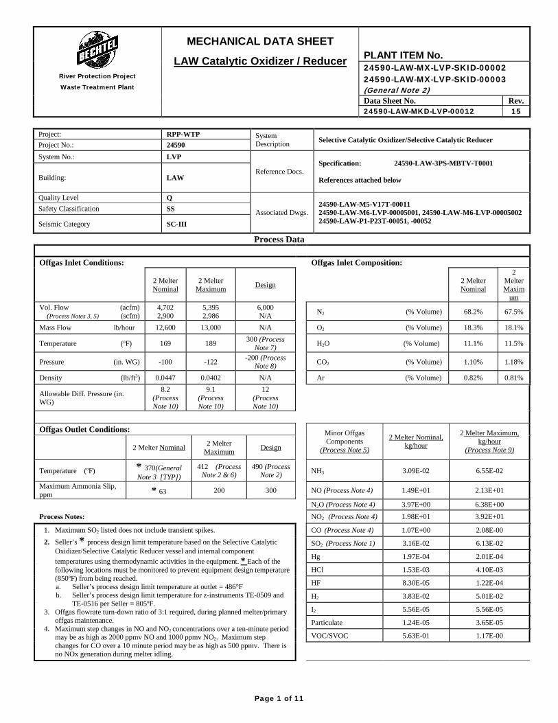
Process Data Offgas Inlet Conditions: Offgas Inlet Composition:
2 Melter Nominal
2 Melter Maximum Design 2 Melter
Nominal
2 Melter Maxim
um
Vol. Flow (acfm) (Process Notes 3, 5) (scfm)
4,702 2,900
5,395 2,986
6,000 N/A N2 (% Volume) 68.2% 67.5%
Mass Flow lb/hour 12,600 13,000 N/A O2 (% Volume) 18.3% 18.1%
Temperature (oF) 169 189 300 (Process Note 7) H2O (% Volume) 11.1% 11.5%
Pressure (in. WG) -100 -122 -200 (Process Note 8) CO2 (% Volume) 1.10% 1.18%
Density (lb/ft3) 0.0447 0.0402 N/A Ar (% Volume) 0.82% 0.81%
Allowable Diff. Pressure (in. WG)
8.2 (Process Note 10)
9.1 (Process Note 10)
12 (Process Note 10)
Offgas Outlet Conditions:
Minor Offgas Components
(Process Note 5)
2 Melter Nominal, kg/hour
2 Melter Maximum, kg/hour
(Process Note 9) 2 Melter Nominal 2 Melter Maximum Design
Temperature (oF) * 370(General Note 3 [TYP])
412 (Process Note 2 & 6)
490 (Process Note 2) NH3 3.09E-02 6.55E-02
Maximum Ammonia Slip, ppm * 63 200 300 NO (Process Note 4) 1.49E+01 2.13E+01
N2O (Process Note 4) 3.97E+00 6.38E+00
Process Notes: NO2 (Process Note 4) 1.98E+01 3.92E+01
1. Maximum SO2 listed does not include transient spikes. 2. Seller’s * process design limit temperature based on the Selective Catalytic
Oxidizer/Selective Catalytic Reducer vessel and internal component temperatures using thermodynamic activities in the equipment. * Each of the following locations must be monitored to prevent equipment design temperature (850ºF) from being reached. a. Seller’s process design limit temperature at outlet = 486°F b. Seller’s process design limit temperature for z-instruments TE-0509 and
TE-0516 per Seller = 805ºF. 3. Offgas flowrate turn-down ratio of 3:1 required, during planned melter/primary
offgas maintenance. 4. Maximum step changes in NO and NO2 concentrations over a ten-minute period
may be as high as 2000 ppmv NO and 1000 ppmv NO2. Maximum step changes for CO over a 10 minute period may be as high as 500 ppmv. There is no NOx generation during melter idling.
CO (Process Note 4) 1.07E+00 2.08E-00
SO2 (Process Note 1) 3.16E-02 6.13E-02
Hg 1.97E-04 2.01E-04
HCl 1.53E-03 4.10E-03
HF 8.30E-05 1.22E-04
H2 3.83E-02 5.01E-02
I2 5.56E-05 5.56E-05
Particulate 1.24E-05 3.65E-05
VOC/SVOC 5.63E-01 1.17E-00
Page 1 of 11
• I I I -r--
- -~ -
I -
I
~
I -I -
I I I I _J ---
I I
!.. _J
River Protection Project
Waste Treatment Plant
MECHANICAL DATA SHEET
LAW Catalytic Oxidizer / Reducer PLANT ITEM No. 24590-LAW-MX-LVP-SKID-00002 24590-LAW-MX-LVP-SKID-00003 (General Note 2) Data Sheet No. Rev. 24590-LAW-MKD-LVP-00012 15
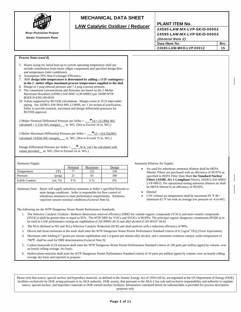
Process Notes (cont’d) 5. Heater sizing for initial heat-up to system operating temperature shall not
include contribution from minor offgas components and specified design flow and temperature (inlet conditions).
6. Assumption-70% Heat Exchanger Efficiency. 7. 300F design inlet temperature is determined by adding a 111F contingency
to the 2- melter offgas maximum process temperature supplied to the skid. 8. Design to 2 psig internal pressure and 7.2 psig external pressure. 9. The constituent concentrations and flowrates are based on the 2-Melter
Maximum flowsheet (24590-LAW-M4C-LOP-00001) per 24590-WTP-BODCN-ENG-09-0018.
10. Values supported by BUYER calculations. Margin exists in TCO inlet/outlet piping. See 24590-LAW-MAJ-MS-12-0009, rev 1 for technical justification. Seller to provide nominal, maximum and design differential pressures for BUYER approval.
2 Melter Nominal Differential Pressure per Seller = ___*14 = (11.89in WG calculated + 2.11in WG margin)___ in. WG. (Not to Exceed 14 in. WG.) 2 Melter Maximum Differential Pressure per Seller = ___*15 = (14.35inWG calculated +0.65in WG margin)___ in. WG. (Not to Exceed 15 in. WG.) Design Differential Pressure per Seller = ___*_N/A, can’t be calculated with values provided__ in. WG. (Not to Exceed 16 in. WG.)
Ammonia Supply:
Ammonia Dilution Air Supply:
Nominal Maximum Design • Air used for anhydrous ammonia dilution shall be HEPA filtered. Filters are purchased with an efficiency of 99.97% as specified in HEPA Filter Data Sheet for Standard Nuclear Filters (ASME AG-1 Compliant Filters), 24590-LAW-MKD-LVP-00015. For operational testing ammonia dilution air shall be HEPA filtered to an efficiency of 99.95%.
• Deleted • C3V exhaust air temperature shall be maximum 95 oF db /
minimum 62 oF wb with an average low pressure of -4 in-WG.
Temperature (oF) 77 125 150 Pressure (psig) 21 45 300 Solids Content (wt. %) 0 % 0 % 0%
Ammonia Note: Buyer will supply anhydrous ammonia at Seller’s specified flowrate to meet design conditions. Seller is responsible for flow control of anhydrous ammonia to meet performance requirements. Ammonia vaporizer assures nominal conditions (General Note 6).
The following are the WTP Dangerous Waste Permit Performance Standards:
1. The Selective Catalytic Oxidizer / Reducer destruction removal efficiency (DRE) for volatile organic compounds (VOCs) and semi-volatile compounds (SVOCs) shall be greater than or equal to 95%. The WTP DRE for VOCs and SVOCs is 99.99%. The principal organic dangerous constituents (PODCs) to be used in LAW performance testing are naphthalene (CAS 00091-20-3) and allyl alcohol (CAS 00107-18-6).
2. The NOx (defined as NO and NO2) Selective Catalytic Reduction (SCR) unit shall perform with a reduction efficiency of 98%. 3. Dioxin and furan emissions at the stack shall meet the WTP Dangerous Waste Permit Performance Standard criteria of 0.2 ng/m3 TEQ (Toxic Equivalent). 4. Maximum inlet loading 0.7 grams per minute naphthalene and 1.4 grams per minute allyl alcohol, and a minimum oxidation catalyst outlet temperature of
700oF shall be used for DRE determination (General Note 9). 5. Carbon monoxide (CO) emission shall meet the WTP Dangerous Waste Permit Performance Standard criteria of 100 parts per million (ppm) by volume, over
an hourly rolling average, dry basis. 6. Hydrocarbon emission shall meet the WTP Dangerous Permit Performance Standard criteria of 10 parts per million (ppm) by volume, over an hourly rolling
average dry basis and reported as propane.
Please note that source, special nuclear and byproduct materials, as defined in the Atomic Energy Act of 1954 (AEA), are regulated at the US Department of Energy (DOE) facilities exclusively by DOE acting pursuant to its AEA authority. DOE asserts, that pursuant to the AEA it has sole and exclusive responsibility and authority to regulate
source, special nuclear, and byproduct materials at DOE-owned nuclear facilities. Information contained herein on radionuclides is provided for process description purposes only
Page 2 of 11
• I I -
~
I
I
- -
- -
-
I I I ~ -I
~
~ -
~ - I ~ -
I
l I

- MECHANICAL DAT A SHEET
VI} LAW Catal~tic Oxidizer/ Reducer PLANT ITEM No. 24590-LAW-MX-LVP-SKI D-00002
River Protection Project 24590-LAW-MX-LVP-SKI D-00003 Waste Treatment Plant (General Note 2)
Data Sheet No. I Rev. 24590-LAW-MKD-LVP-00012 I 15
A ,oorova s Deleted EQ infom,ation from this data sheet. Transferred EQ infom,ation to data sheets, 24590-LAW-MKQ-M40T-00001 and 00002. Up dated process note 7. Revised requirements for ammonia dilution air supply. Updated ammonia skid width. Deleted nozzle loads tables Accepted 0 and added reference to the No Comments
15 calculation number defining the By: Mike O'Neill - mroneal Checked ✓ Org Name: LAW Sys Erq
nozzle loads. Updated catalyst Placed: Oct 22, 2015 , 10:44 Ml By: lance l8'Ms - k:lewis2
Org Name: LAW MH/RE
lf!?D weights and references. Margin is P\aced; Oct 22. 2015, 10:35 am not affected. This datasheet
Originator summarizes technical data 1G developed in calculations and By: Dennis J Rickettson - djrickel
od reports or documented in design Org Name: Mecharic81 Systems
Placed: Oct 22, 2015, 10:27 am
/) basis documents. These documents contain the marain. MO'Neill DRickettson L Lewis NIA NIA G Goolsby Updated the revision numbers for the corrosion evaluations . Margin is not
14 reduced . Updating revision numbers for the corrosion evaluations does not p 07/01 reduce marqin. MO'Neill D Rickettson L Lewis NIA NIA Rajagopalan 115 Deleted "Piping" from the Piping /Ducting header. Under Electric Heater section, added "Materials in contact with offgas", deleted enclosure material type & 347SS. Deleted "high temp surface & Instr housing matl", added matl in contact with offgas, added lnconel 800.
13 Revised submittal number 24590-CD-POC-MBT0-00007-01-00386 to 24590-CD-POC-MBT0-00007-01-00353. Revised General Note 11 . Margin is not affected. This datasheet summarizes technical data developed in calculations and reports or documented in design basis documents. These documents p 06/ 18 contain the marqin. MO'Neill D Rickettson L Lewis NIA NIA Rajag;opalan /15 Deleted reference to MACT and replaced with Perfom,ance Standards consistant with the DWP. Deleted E&NS Safety Screening Required statement. Updated maximum Heat
12 loss to 17.6 kW. Deleted reference to "General Note 1 O". Deleted General note 5. Deleted redundant requirement for shipping weights. Added note 1 to EQ section 1.1 1. p s 03/20 Updated references as required. MO'Neill D Rickettson J Marsh NIA Leatherbarrow Kretzschmar 115
Page 3 of 11
River Protection Project
Waste Treatment Plant
MECHANICAL DATA SHEET
LAW Catalytic Oxidizer / Reducer PLANT ITEM No. 24590-LAW-MX-LVP-SKID-00002 24590-LAW-MX-LVP-SKID-00003 (General Note 2) Data Sheet No. Rev. 24590-LAW-MKD-LVP-00012 15
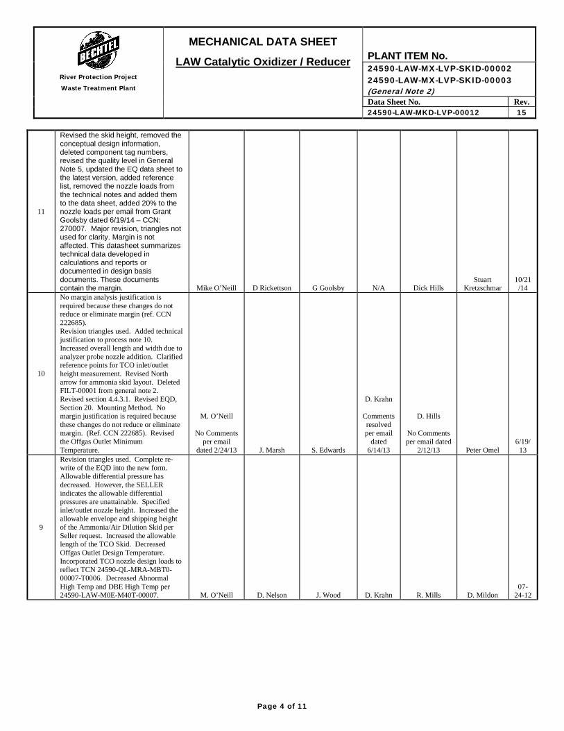
11
Revised the skid height, removed the conceptual design information, deleted component tag numbers, revised the quality level in General Note 5, updated the EQ data sheet to the latest version, added reference list, removed the nozzle loads from the technical notes and added them to the data sheet, added 20% to the nozzle loads per email from Grant Goolsby dated 6/19/14 – CCN: 270007. Major revision, triangles not used for clarity. Margin is not affected. This datasheet summarizes technical data developed in calculations and reports or documented in design basis documents. These documents contain the margin. Mike O’Neill D Rickettson G Goolsby N/A Dick Hills
Stuart Kretzschmar
10/21/14
10
No margin analysis justification is required because these changes do not reduce or eliminate margin (ref. CCN 222685). Revision triangles used. Added technical justification to process note 10. Increased overall length and width due to analyzer probe nozzle addition. Clarified reference points for TCO inlet/outlet height measurement. Revised North arrow for ammonia skid layout. Deleted FILT-00001 from general note 2. Revised section 4.4.3.1. Revised EQD, Section 20. Mounting Method. No margin justification is required because these changes do not reduce or eliminate margin. (Ref. CCN 222685). Revised the Offgas Outlet Minimum Temperature.
M. O’Neill
No Comments per email
dated 2/24/13 J. Marsh S. Edwards
D. Krahn
Comments resolved per email
dated 6/14/13
D. Hills
No Comments per email dated
2/12/13 Peter Omel 6/19/
13
9
Revision triangles used. Complete re-write of the EQD into the new form. Allowable differential pressure has decreased. However, the SELLER indicates the allowable differential pressures are unattainable. Specified inlet/outlet nozzle height. Increased the allowable envelope and shipping height of the Ammonia/Air Dilution Skid per Seller request. Increased the allowable length of the TCO Skid. Decreased Offgas Outlet Design Temperature. Incorporated TCO nozzle design loads to reflect TCN 24590-QL-MRA-MBT0-00007-T0006. Decreased Abnormal High Temp and DBE High Temp per 24590-LAW-M0E-M40T-00007.
M. O’Neill
D. Nelson
J. Wood
D. Krahn
R. Mills
D. Mildon 07-
24-12
Page 4 of 11
• I I I -~ -
-
~
L I I I I I I I I I

River Protection Project
Waste Treatment Plant
MECHANICAL DATA SHEET
LAW Catalytic Oxidizer / Reducer PLANT ITEM No. 24590-LAW-MX-LVP-SKID-00002 24590-LAW-MX-LVP-SKID-00003 (General Note 2) Data Sheet No. Rev. 24590-LAW-MKD-LVP-00012 15
8
Revision triangles used. Removed cancelled process calculation 24590-LAW-MEC-LVP-00001. Revised component flowrates to align with 2-Melter Maximum flow sheet guidance per 24590-WTP-BODCN-ENG-09-0018 and ECCN # 24590-LAW-M4E-LOP-00009. Increased the allowable ammonia/air dilution skid height to 11’-0”. Specified dilution air flowrate, heat transfer coefficient and heat exchanger area.
M. O’Neill
D. Nelson
M. Parker
D. Krahn
K. Simon
D. Mildon 12-
15-11
7
Revision triangles used. Revised Allowable Differential Pressure. Revised Construction Data (Section height, Overall height). Revised catalyst data per manufacturer’s and Seller’s recommendations. For the EQD portion of the MDS, revised the requisition number, LAW Room datasheet revision number, the area classification “R” value and the chemical exposure details.
M. O’Neill
D. Nelson
D. Rickettson
D. Krahn
K. Simon
J. Schneider 04-
18-11
6 Major Revision. Revision triangles not used.
M. O’Neill
T. Valenti
D. Rickettson
D. Krahn K. Simon
J. Roth 01-
12-10 5 Revised General Notes 7 & 8. Revised
Process Data. Revised Material Selection for subcomponents based on MET Corrosion Analyses Added reference to LAW C3 Cost Benefit Analysis. Clarified dimensions of skid. Misc. editorial changes.
Mike O’Neill
Josh Wood
Ray Peters
Dwight Krahn
Jeff White
John Julyk
04-Sep-08
4 Added plant item number for ammonia supply skid. Updated quality level designator. Added safety classification. Updated process data. Revised general note 4, added general note 7, 8, & 9. Revised note 5 & 6, and added note 7 for ammonia skid requirements. Revised reference process calculation. Added approval signature block for E&NS. Increased size of ammonia skid sketch for clarity. Added Attachment 1. Added EQ datasheets and Sketch. Added new process data from 24590-LAW-M4C-LOP-00001, Rev. 0. Updated reference P&IDs.
Mike O’Neill
Grant Goolsby
Utpal Sen
Dwight Krahn
Dick Hills
John Julyk
14-Feb-08
3 Revised housing material, system performance and added NOx concentration step change requirement. R. Hanson D. Pease C. Morley N/A N/A M Hoffmann
31-Jul-05
2
Revised pressures and catalyst model number per SDDR 24590-WTP-SDDR-PROC-04-00879. Added dilution air, outlet piping, and ammonia skid requirements. R. Hanson D. Pease C. Morley N/A N/A M. Hoffmann
31-Oct-04
1 Revised Seller Information J. Rewari / S. Colby D. Pease C. Morley N/A N/A M. Hoffmann
6-May-
04
0 Issued for Purchase J. Rewari / S. Colby D. Pease E. Isern N/A N/A M. Hoffmann
18-Apr-04
Rev Reason for revision Mech Sys/ Proc. Eng.
Project Equipment Checked E&NS EQ Approved Date
Page 5 of 11
• I I I -~ -
~ -
- -
-
~
~
~
~ -
~ -I I I I I I I I I _J

River Protection Project
Waste Treatment Plant
MECHANICAL DATA SHEET
LAW Catalytic Oxidizer / Reducer PLANT ITEM No. 24590-LAW-MX-LVP-SKID-00002 24590-LAW-MX-LVP-SKID-00003 (General Note 2) Data Sheet No. Rev. 24590-LAW-MKD-LVP-00012 15
Mechanical Data (Buyer)
Construction Data: Process Equipment Dimensions (L x W x H): Ammonia/ Air Dilution Equipment (L x W x H):
Sections (Applicable Only to SCO/SCR skid components/sections that will require replacement prior to 40 years)
15’-6” x 9’-0” x 13’-0” ft Skid dimensions with dilution air fans 13’-0” x 9’-6” x 12’-0” ft
Overall-Less Maximum TCO Inlet/Outlet Expansion Joint Height (See Below) 44’-6” x 10’-0” x 13’-0” ft Skid dimensions without
dilution air fans N/A ft TCO Inlet/Outlet Expansion Joint Height (Maximum-From Frame Base to Top of Inlet/Outlet Bellows Flanges)
12’-6” ft Operating Weight *18,000 (est.) lb
Operating Weight *103,000 (est.) lb Shipping Dimensions 13’-0” x 9’-6” x 12’-0” ft
Shipping Dimensions
*Length: 13.5 (Heater) Width: 6.5 (Heat Ex.) Height: 8.5 (Heat Ex.)
(est.)
ft Shipping Weight *18,000 (est.) lb
Shipping Weight *20,000 (est) lb Thermal Analysis Data:
Room Temperature 59-95 oF Concrete Slab Base Thickness 10 in
Room Temperature Under Floor 59-95 oF Thermal Conductivity of Concrete Slab 1.8 W / m-K
Maximum Heat Loss 17.6 kW Room Pressure Atm. Less 0.2 in-WG
Thermal Cycling Frequency: Per 24590-WTP-MVC-50-00009, Rev 00B, use a thermal cycle total of 100 for the life of the plant (40 years).
System Performance (Seller, General Note 1)
Volatile Organic DRE *95 % Semi-Volatile Organic DRE *95 % NOx Reduction *98 % Ammonia consumption, max *89 lb/hr NOx emissions, max
*160 ppmvw Ammonia entering injection chamber: Pressure *15.8 in-WG
Ammonia slip, max *200 ppmvw Flow *92 lb/hr Ammonia/NOx molar injection ratio *4:3 Temp. *96 oF Overall Pressure drop through Oxidizer
*10.9 (dP=SCO+SCR) in-WG Dilution Air entering injection chamber: Pressure *15.8 in-WG
Minimum service life catalyst: Flow 800 scfm Oxidation Catalyst *3 yrs (EST.)
NOx Catalyst *3 yrs (EST.)
Page 6 of 11
• I -
1~ 7
I 7
I I I l
~
I -
I I I -
I _J
-
-
I I _J
I J I - 1--
I _J -I
J

River Protection Project
Waste Treatment Plant
MECHANICAL DATA SHEET
LAW Catalytic Oxidizer / Reducer PLANT ITEM No. 24590-LAW-MX-LVP-SKID-00002 24590-LAW-MX-LVP-SKID-00003 (General Note 2) Data Sheet No. Rev. 24590-LAW-MKD-LVP-00012 15
Nozzle Loading (Buyer)
LAW TCO Nozzle Design Loads (LVP-SKID-00002) are defined in calculation, 24590-LAW-MVC-LVP-00004. Ammonia / Air Dilution Design Nozzle Loads (LVP-SKID-00003) are defined in calculation, 24590-LAW-S0C-S15T-
00030.
Page 7 of 11
• I ----r rt=========r:: ~. r

River Protection Project
Waste Treatment Plant
MECHANICAL DATA SHEET
LAW Catalytic Oxidizer / Reducer PLANT ITEM No. 24590-LAW-MX-LVP-SKID-00002 24590-LAW-MX-LVP-SKID-00003 (General Note 2) Data Sheet No. Rev. 24590-LAW-MKD-LVP-00012 15
Components (Seller, General Note 1)
Catalyst: Organic (LVP-SCO-00001) NOx (LVP-SCR-00001)
Manufacturer BASF (VOCat 300S) “Source Controlled” *BASF NOxCat VNX-300 Number of reactors 1 1 Number of catalyst modules per layer *12 *12 Residence time (at standard conditions), seconds, minimum. 0.77 (General Note 8) *0.91
Arrangement *4 wide x 3 high *4 wide x 3 high Total reactor catalyst volume, cubic feet, minimum. 39/ * 39.6 (actual) *59 Type Precious metal - platinum *Vanadium/Titanium Material: base/substrate Ceramic - cordierite *Ceramic - cordierite Total Number of layers per reactor 3 4/ *5 (actual) Thickness of layer, in *10 *9 Space provided between layers for remixing Yes *Yes Space for additional layer, in No *No Is dummy layer provided No *No Number of flow passages 230 cpsi *64 cpsi Flow passage, in. x in. 0.060” x 0.060” *0.11” x 0.11” Face velocity thru reactor, fpm *639 *750 Catalyst Section Pressure Drop, in WG *6.72 *4.18 Inlet Offgas Temperature for MACT Performance Testing, oF 720 (Min) - 750 (Maximum) *607-631
Design temp, oF * 850 * 850 Catalyst Module Dimensions, (L x W x D) *18” x 12” x 10” *18” x 12” x 9” Catalyst Module weight, lb * 65.8 * 57.7 Total weight of catalyst reactor, lb * 2,369 * 3,462
Components (Seller, General Note 1)
Housing: LVP-SCO-00001 LVP-SCR-00001 Material Type 347 SS 347 SS Material/Thickness, in *3/8 *3/8 Number of Sections *1 *1 Weight of Heaviest Section, lb *10,100 (est.) *16,300 (est.) Insulation * * Material/Thickness, in * * Corrosion Allowance, in (General Note 11) 0.010 0.010 Thermal Cond, Btu-in/hr ft2 oF * * Method of Attachment *Studs with clips *Studs with clips Design pressure, psig (internal/external) * See Offgas Inlet Conditions on Page 1 Operating pressure, psig *See Offgas Inlet Conditions on Page 1 Design temperature, oF * 850
Page 8 of 11
• I ----r rb=========:=:3:==3. r
--
--
--
-

River Protection Project
Waste Treatment Plant
MECHANICAL DATA SHEET
LAW Catalytic Oxidizer / Reducer PLANT ITEM No. 24590-LAW-MX-LVP-SKID-00002 24590-LAW-MX-LVP-SKID-00003 (General Note 2) Data Sheet No. Rev. 24590-LAW-MKD-LVP-00012 15
Components (Seller, General Note 1)
Ducting: Inlet Outlet Material/Thickness, in *3/8 *3/8 Cross Section, ft x ft *47 – 1/8” x 26” *47-1/8” x 26” Duct Velocity, fpm *1143 *1203 Design Temperature, oF *850 *850
Electric Heater (LVP-HTR-00002) Manufacturer * Type *Tubular elements Number of Heat Zones *5 Watt Density, W/in2 *8.5 Power, kW *310 Voltage/Current rating *480V / TBD Housing Material Type *347 SS Materials in contact with offgas, Corrosion Allowance, in (General Note 11) 0.010
Heating Elements Incoloy 800 Materials in contact with offgas 347 SS, Incoloy 800 Design Temperature oF *850
Recuperative Heat Exchanger (LVP-HX-00001) Manufacturer *Munters Corporation – DES Champs Products Type *Plate/Frame Structural Support Material Type *347 SS Cold Side Components & Enclosure Material Type 347 SS Hot Side Plate/Membrane Material Type 347 SS Heat transfer coefficient, Btu/hr ft2 oF-Minimum 3.4 Heat exchange area, ft2-Minimum 3105 ∆T (LMTD) oF *152 (est.) Heat Exchanger duty, Btu/hr *1,844,030 (est.) Corrosion Allowance, in (General Note 11) 0.010 Design Temperature oF * 850
Ammonia Injection Manifold: Type/Arrangement *3” injection pipes, horizontal Feed Inlet Dia. in *8 Supply Pressure/Temp (psi/oF) *0.57 psig / 96ºF (at manifold)
Material Type (SCR Piping) 347 SS (Vessel Internals) 316L SS (External to Vessel)
No. of nozzle bars per manifold *6 No. of nozzles per bar *1,138 Spacing between nozzles, in *Vertical: 15° / Horizontal: ½” staggered Nozzle opening diameter, in *0.1
Page 9 of 11
• I -
[ I I J ~
~
-I I
I --
~ -
- -
-
-
--
~ -
- --
I -
-
-
-
-
r-- -
~ -
~ -
~ --
~
I ~
~
I r--
.--,-----
,__ t-- -t---
C I J

River Protection Project
Waste Treatment Plant
MECHANICAL DATA SHEET
LAW Catalytic Oxidizer / Reducer PLANT ITEM No. 24590-LAW-MX-LVP-SKID-00002 24590-LAW-MX-LVP-SKID-00003 (General Note 2) Data Sheet No. Rev. 24590-LAW-MKD-LVP-00012 15
LVP-SKID-00002, Catalytic Oxidizer/Reducer Skid Layout
This sketch has been replaced by 24590-CD-POC-MBT0-00007-01-00353
LVP-SKID-00003, Ammonia/Air Dilution Skid Layout
This sketch has been replaced by 24590-CD-POC-MBT0-00007-01-00175.
Page 10 of 11
I • I
- r -
r I !,_ r I I
I
-•
River Protection Project
Waste Treatment Plant
MECHANICAL DATA SHEET
LAW Catalytic Oxidizer / Reducer PLANT ITEM No. 24590-LAW-MX-LVP-SKID-00002 24590-LAW-MX-LVP-SKID-00003 (General Note 2) Data Sheet No. Rev. 24590-LAW-MKD-LVP-00012 15
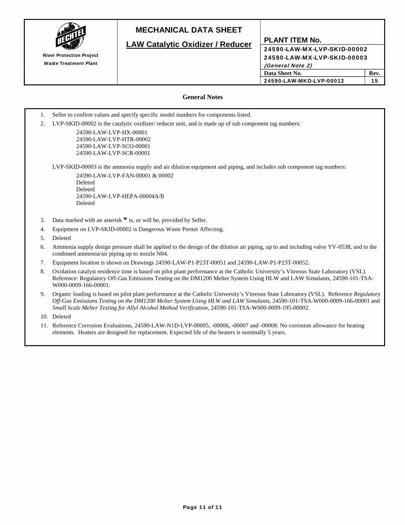
General Notes
1. Seller to confirm values and specify specific model numbers for components listed. 2. LVP-SKID-00002 is the catalytic oxidizer/ reducer unit, and is made up of sub component tag numbers:
24590-LAW-LVP-HX-00001 24590-LAW-LVP-HTR-00002 24590-LAW-LVP-SCO-00001 24590-LAW-LVP-SCR-00001
LVP-SKID-00003 is the ammonia supply and air dilution equipment and piping, and includes sub component tag numbers:
24590-LAW-LVP-FAN-00001 & 00002 Deleted Deleted 24590-LAW-LVP-HEPA-00004A/B Deleted
3. Data marked with an asterisk * is, or will be, provided by Seller. 4. Equipment on LVP-SKID-00002 is Dangerous Waste Permit Affecting. 5. Deleted 6. Ammonia supply design pressure shall be applied to the design of the dilution air piping, up to and including valve YV-0538, and to the
combined ammonia/air piping up to nozzle N04. 7. Equipment location is shown on Drawings 24590-LAW-P1-P23T-00051 and 24590-LAW-P1-P23T-00052. 8. Oxidation catalyst residence time is based on pilot plant performance at the Catholic University’s Vitreous State Laboratory (VSL).
Reference: Regulatory Off-Gas Emissions Testing on the DM1200 Melter System Using HLW and LAW Simulants, 24590-101-TSA-W000-0009-166-00001.
9. Organic loading is based on pilot plant performance at the Catholic University’s Vitreous State Laboratory (VSL). Reference Regulatory Off-Gas Emissions Testing on the DM1200 Melter System Using HLW and LAW Simulants, 24590-101-TSA-W000-0009-166-00001 and Small Scale Melter Testing for Allyl Alcohol Method Verification, 24590-101-TSA-W000-0009-195-00002.
10. Deleted 11. Reference Corrosion Evaluations, 24590-LAW-N1D-LVP-00005, -00006, -00007 and -00008. No corrosion allowance for heating
elements. Heaters are designed for replacement. Expected life of the heaters is nominally 5 years.
Page 11 of 11
• I -
1~ -

REFERENCES for Data Sheet: 24590-LAW-MKD-LVP-00012, Rev 15 (For BNI Use only)
Data Document # Rev Document Title
Quality Level 24590-LAW-M6-LVP-00005001 24590-LAW-M6-LVP-00005002
3 3
P&ID – LAW Secondary Offgas/Vessel Vent Process System Ammonia Dilution Skid P&ID-LAW-Secondary Offgas/Vessel Vent Process System SCO/SCR Skid
Seismic Category 24590-LAW-M6-LVP-00005001 24590-LAW-M6-LVP-00005002
3 3
P&ID – LAW Secondary Offgas/Vessel Vent Process System Ammonia Dilution Skid P&ID-LAW-Secondary Offgas/Vessel Vent Process System SCO/SCR Skid
2 Melter Maximum Flow Rate 24590-LAW-MKC-LVP-00003 1 LAW Catalytic Oxidizer/Reducer Skid Inlet Operating Conditions and Design Requirements, page 7
Design Volumetric Flow Rate 24590-LAW-MKC-LVP-00003 1 LAW Catalytic Oxidizer/Reducer Skid Inlet Operating Conditions and Design Requirements, page 9
2 Melter Nominal Inlet Temperature
24590-LAW-MKC-LVP-00003 1 LAW Catalytic Oxidizer/Reducer Skid Inlet Operating Conditions and Design Requirements, page 7
2 Melter Maximum Inlet Temperature
24590-LAW-MKC-LVP-00003 1 LAW Catalytic Oxidizer/Reducer Skid Inlet Operating Conditions and Design Requirements, page 7
Design Inlet Temperature 24590-LAW-M4E-LOP-00009 N/A LAW Melter Offgas System Design Basis Flow Sheets, Page 15
Maximum Outlet Temperature 24590-LAW-MKC-LVP-00003 1 LAW Catalytic Oxidizer/Reducer Skid Inlet Operating Conditions and Design Requirements, page 3
Design Outlet Temperature 24590-LAW-MKC-LVP-00003 1 LAW Catalytic Oxidizer/Reducer Skid Inlet Operating Conditions and Design Requirements, page 7
2 Melter Nominal Pressure 24590-LAW-MKC-LVP-00003 1 LAW Catalytic Oxidizer/Reducer Skid Inlet Operating Conditions and Design Requirements, page 7
2 Melter Maximum Pressure 24590-LAW-MKC-LVP-00003 1 LAW Catalytic Oxidizer/Reducer Skid Inlet Operating Conditions and Design Requirements, page 7
Design Inlet Pressure (Vacuum) 24590-LAW-MKC-LVP-00003 1 LAW Catalytic Oxidizer/Reducer Skid Inlet Operating Conditions and Design Requirements, page 8 Allowable Differential Pressure (Nominal)
24590-LAW-M4E-LOP-00009 N/A LAW Melter Offgas System Design Basis Flow Sheets, Page 11
Allowable Differential Pressure (Maximum)
24590-LAW-M4E-LOP-00009 N/A LAW Melter Offgas System Design Basis Flow Sheets, Page15
Allowable Differential Pressure (Design)
24590-LAW-MKC-LVP-00003 1 LAW Catalytic Oxidizer/Reducer Skid Inlet Operating Conditions and Design Requirements, page 9
2 Melter Maximum Mass Flow 24590-LAW-M4E-LOP-00009 N/A LAW Melter Offgas System Design Basis Flow Sheets, Page15
2 Melter Maximum Density 24590-LAW-M4E-LOP-00009 N/A LAW Melter Offgas System Design Basis Flow Sheets, Page 15
2 Melter Nominal Mass Flow 24590-LAW-M4E-LOP-00009 N/A LAW Melter Offgas System Design Basis Flow Sheets, Page 11
2 Melter Nominal Density 24590-LAW-M4E-LOP-00009 N/A LAW Melter Offgas System Design Basis Flow Sheets, Page 11
2 Melter Nominal Volumetric Flow 24590-LAW-M4E-LOP-00009 N/A LAW Melter Offgas System Design Basis Flow Sheets, Page 11
2 Melter Nominal Offgas Composition
24590-LAW-M4E-LOP-00009
N/A LAW Melter Offgas System Design Basis Flow Sheets, Pages 12-14
Page 1 of 3

REFERENCES for Data Sheet: 24590-LAW-MKD-LVP-00012, Rev 15 (For BNI Use only)
2 Melter Maximum Offgas Composition 24590-LAW-M4E-LOP-00009 N/A LAW Melter Offgas System Design Basis Flow Sheets, Pages 16-18
Ammonia Supply Conditions 24590-LAW-M6WX-LVP-00005001
2 MS Line List for P&ID 24590-LAW-M6-LVP-00005001, Page 1
Maximum Ammonia Slip 24590-LAW-M4E-LOP-00009 N/A LAW Melter Offgas System Design Basis Flow Sheets, Page 17
Design Ammonia Slip 24590-LAW-MKC-LVP-00003 1 LAW Catalytic Oxidizer/Reducer Skid Inlet Operating Conditions and Design Requirements, page 6
VOC Removal Efficiency 24590-WTP-DB-ENG-01-001 2 Basis of Design, Section 14.4.3.3
Maximum Offgas Inlet Composition
24590-LAW-M4E-LOP-00009 N/A LAW Melter Offgas System Design Basis Flow Sheets, page 16
Minor Offgas Components 24590-LAW-M4E-LOP-00009 N/A LAW Melter Offgas System Design Basis Flow Sheets, pages 17 and 18
Mechanical Data – Ammonia / Air Dilution Skid
24590-CD-POC-MBT0-00007-01-00042
00D LAW Ammonia / Air Dilution Skid General Arrangement
Nozzle Loads LVP-SKID-00002 24590-LAW-MVC-LVP-00004 00A LVP-SKID-00002, LAW Thermal Catalytic Oxidizer / Reducer, Stress Analysis with ANSYS
Nozzle Loads LVP-SKID-00003 24590-LAW-S0C-S15T-00030 00A LAWTCO Ammonia/Air Dilution Skid Analysis
Deleted
Catalyst Data (Organic) 24590-CD-POC-MBT0-00007-03-00003
00D Data Sheet – Selective Catalytic Oxidation(SCO) Catalyst
Catalyst Data (NOx) 24590-CD-POC-MBT0-00007-03-00004
00D Data Sheet – Selective Catalytic Reduction (SCR) Catalyst
Nominal and Maximum Pressure Differential
24590-CD-POC-MBT0-00007-02-00001
00E Calculation – Mass & Energy Balance for LAW Catalytic Oxidizer / Reducer
LVP-SCR-00001 Material Type and Corrosion Allowance
24590-LAW-N1D-LVP-00008 3 LVP-SCR-00001 (LAW) – NOx Selective Catalytic Reducer
LVP-SCO-00001 Material Type and Corrosion Allowance
24590-LAW-N1D-LVP-00007 4 LVP-SCO-00001 (LAW) – Thermal Catalytic Oxidizer
LVP-HTR-00002 Material Type and Corrosion Allowance
24590-LAW-N1D-LVP-00006 3 LVP-HTR-00002 (LAW) – Catalytic Oxidizer Electric Heater
LVP-HX-00001 Material Type and Corrosion Allowance
24590-LAW-N1D-LVP-00005 3 LVP-HX-00001 (LAW) – Catalytic Oxidizer Heat Recovery Exchanger
Construction Data 24590-CD-POC-MBT0-00007-03-00001
00C Data Sheet – Mechanical Data Sheet, LAW Catalytic Oxidizer/Reducer
Electric Heater 24590-CD-POC-MBT0-00007-03-00009
00F Data Sheet – Electric Heater, LAW TCO
Recuperative Heat Exchanger 24590-CD-POC-MBT0-00007-03-00008
00D Data Sheet – Heat Exchanger Core, LAW TCO
Page 2 of 3
I
I
I I
I
I

REFERENCES for Data Sheet: 24590-LAW-MKD-LVP-00012, Rev 15 (For BNI Use only)
Vendor Provided Data 24590-CD-POC-MBT0-00007-03-00001
00C Data Sheet - Mechanical Data Sheet, LAW Catalytic Oxidizer / Reducer
Maximum Heat Loss 24590-LAW-MVC-LVP-00004 00A LVP-SKID-00002, LAW Thermal Catalytic Oxidizer / Reducer, Stress Analysis with ANSYS
Point of Support 24590-LAW-P1-P23T-01009001 0 LAW Vitrification Building Equipment Location Point of Support Schedule Elevation 48’-0” Sheet 1 of 2
Page 3 of 3
I
I I