mechanical clamping elements - lenze selection · mecheaneielmpgca...
TRANSCRIPT

Mechanicalclamping elements
Clamping sets, rigid shaft couplings, shrink discs

2 Lenze Selection · Mechanical clamping elements en 04/2016

3Lenze Selection · Mechanical clamping elements en 04/2016
IntroductionSelection guide
Overview
Clamping sets/Application examples
Clamping sets/Calculation of the minimum hub diameter DM
Clamping sets
TLK 110
TLK 130/131
TLK 132/133
TLK 134
TLK 139
TLK 200
TLK 250/250L
TLK 300
TLK 350
TLK 400/401
TLK 450
TLK 451/451.0
TLK 452
Rigid shaft couplings
TLK500
Shrink discs
TLK 603/602/601
TLK 622/623/683
Contents
Page78
1012
14
16
18
20
22
24
26
28
30
32
34
36
38
40
41
47

4 Lenze Selection · Mechanical clamping elements en 04/2016
Drive components are our world.

5Lenze Selection · Mechanical clamping elements en 04/2016
13
Electromagnetically actuated clutches and brakes
Shaft couplings
Torque limiters
Locking assemblies
Universal jointsBelt drives
Linear Motion

6 Lenze Selection · Mechanical clamping elements en 04/2016
Meeting individual customer requirements – and keeping everything securely clamped in place.
Mechanical clamping sets and shrink discs are used for friction-locked and backlash-free connection of shafts and hubs or other machine parts so that torques and axial forces are transmitted successfully between these components.
With our standard portfolio, we supply mechanical clamping sets for shaft diameters of 6 mm to 800 mm and torques of 6 Nm to 2,131,000 Nm. We also supply mechanical shrink discs for shaft diameters of 9 mm to 540 mm and torques of 20 Nm to 4,028,000 Nm.
We will work with you to design your individual solution for friction-locked connection of your mechanical shafts and hubs.
The advantages of friction-locked transmission of torque compared to keyway connections are, for example, long-lasting and indestructible connections, speedy, reliable and easy mounting/removal and the total absence of any backlash. Clamping sets are therefore especially suitable for servo technology and reversing duty. The torque can be transmitted while axial forces are absorbed.

7Lenze Selection · Mechanical clamping elements en 04/2016
Selection guide
Selection of mechanical clamping elements
Selection of the series on the basis of its geometry and performance data
TLK 130 TLK 132 TLK 139 TLK 250L TLK 350 TLK 450
TLK 451/TLK451.0TLK 452
TLK 110 TLK 131 TLK 133 TLK 134 TLK 400
TLK 401/TLK 401.0
TLK 200TLK 250TLK 300
TLK 601TLK 602TLK 603TLK 622TLK 681TLK 623TLK 686
TLK500
With axial hub movement ...
… during mounting of the clamping set. Catalogue values are applicable if hub can be displaced freely.
Without axial hub movement ...
… during mounting of the clamping set.
Self-centering
Shaft and hub are centred in relation to each other by means of clamping set. Additional centering of the hub is not necessary.
Not self-centering
Centering between shaft and hub necessary
Clamping sets
They are placed between shaft and hub and result in a friction-locked connection between clamping set and shaft and between clamping set and hub.
Rigid shaft couplings
They are positioned on two opposite shaft ends. Friction locking between coupling and shaft ends
Shrink discs
Are placed on hub/hollow shaft. Friction locking between shaft and hub/hollow shaft
Shaft
Hub
Shaft Shaft 1 Shaft 2
Centering
before mounting before mounting
after mounting axial movement of the hub
after mounting no axial movement of the hub

8 Lenze Selection · Mechanical clamping elements en 04/2016
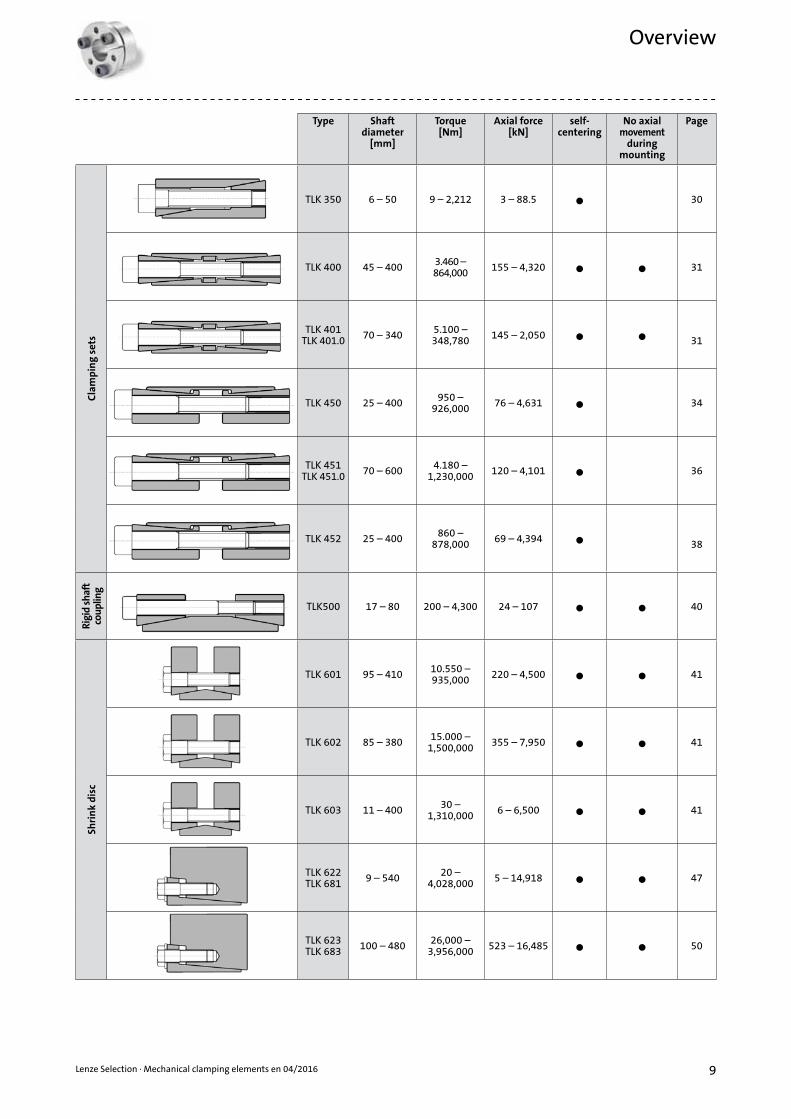
Overview
Type Shaft diameter
[mm]
Torque[Nm]
Axial force[kN]
self-centering
No axial movement
during mounting
Page
Cla
mp
ing
sets
TLK 110 6 – 130 16 – 25,000 6 – 389 • • 14
TLK 130 18 – 240 490 – 133,700 55 – 1.114 • 16
TLK 131 18 – 240 300 – 83,350 34 – 695 • • 16
TLK 132 18 – 200 330 – 66,250 38 – 662 • 18
TLK 133 18 – 240 250 – 50,000 28 – 500 • • 18
TLK 134 14 – 50 290 – 1,840 42 – 74 • • 20
TLK 139 18 – 90 210 – 7,500 23.7 – 168.5 • 22
TLK 200 17 – 800 300 – 2,131,000 35 – 5,327 • 24
TLK 250 14 – 70 38 – 1,240 5 – 35 26
TLK 250L 14 – 60 64 – 1,360 9 – 45 • 26
TLK 300 6 – 540 2 – 400,000 0,84 – 1,480 28
9Lenze Selection · Mechanical clamping elements en 04/2016
Overview
Type Shaft diameter
[mm]
Torque[Nm]
Axial force[kN]
self-centering
No axial movement
during mounting
Page
Cla
mp
ing
sets
TLK 350 6 – 50 9 – 2,212 3 – 88.5 • 30
TLK 400 45 – 400 3.460 – 864,000 155 – 4,320 • • 31
TLK 401TLK 401.0 70 – 340 5.100 –
348,780 145 – 2,050 • • 31
TLK 450 25 – 400 950 – 926,000 76 – 4,631 • 34
TLK 451TLK 451.0 70 – 600 4.180 –
1,230,000 120 – 4,101 • 36
TLK 452 25 – 400 860 – 878,000 69 – 4,394 • 38
Rigi
d sh
aft
coup
ling
TLK500 17 – 80 200 – 4,300 24 – 107 • • 40
Shri
nk
dis
c
TLK 601 95 – 410 10.550 – 935,000 220 – 4,500 • • 41
TLK 602 85 – 380 15.000 – 1,500,000 355 – 7,950 • • 41
TLK 603 11 – 400 30 – 1,310,000 6 – 6,500 • • 41
TLK 622TLK 681 9 – 540 20 –
4,028,000 5 – 14,918 • • 47
TLK 623TLK 683 100 – 480 26,000 –
3,956,000 523 – 16,485 • • 50

10 Lenze Selection · Mechanical clamping elements en 04/2016
Clamping setsApplication examples
Axial bearing clamping and gear attachment by means of TLK350 Sprocket clamping by means of TLK 130 with non-cut outer ring
TLK821 for cardan-shaft mounting Clamping of a brake disk by means of TLK 700
Hub connection by means of TLK 200 with centering ring Connection of a large hub by means of TLK 400

11Lenze Selection · Mechanical clamping elements en 04/2016
Clamping setsApplication examples
Special version TLK 133 for hub attachment Use of TLK 300 without spacer
Use of several clamping sets for high torques Use of TLK 110 for high speeds
Special version TLK 132 with protective ring for the screws Special version TLK 132 with sealing rings
12 Lenze Selection · Mechanical clamping elements en 04/2016
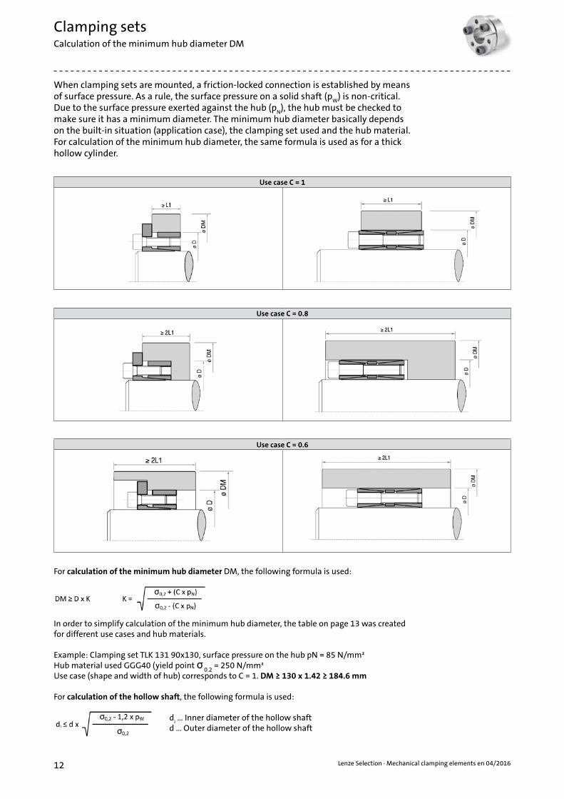
When clamping sets are mounted, a friction-locked connection is established by means of surface pressure. As a rule, the surface pressure on a solid shaft (p
W) is non-critical.
Due to the surface pressure exerted against the hub (pN), the hub must be checked to
make sure it has a minimum diameter. The minimum hub diameter basically depends on the built-in situation (application case), the clamping set used and the hub material. For calculation of the minimum hub diameter, the same formula is used as for a thick hollow cylinder.
For calculation of the minimum hub diameter DM, the following formula is used:
In order to simplify calculation of the minimum hub diameter, the table on page 13 was created for different use cases and hub materials.
Example: Clamping set TLK 131 90x130, surface pressure on the hub pN = 85 N/mm² Hub material used GGG40 (yield point
0.2 = 250 N/mm²
Use case (shape and width of hub) corresponds to C = 1. DM ≥ 130 x 1.42 ≥ 184.6 mm
For calculation of the hollow shaft, the following formula is used:
di … Inner diameter of the hollow shaft
d … Outer diameter of the hollow shaft
Clamping setsCalculation of the minimum hub diameter DM
Use case C = 1
Use case C = 0.8
Use case C = 0.6

13Lenze Selection · Mechanical clamping elements en 04/2016
Surface pressure on hub σ0.2
Yield point [N/mm2]
150 180 200 220 250 270 300 350 400 450 600
pN
[N/mm2]Type of
useC
Material
GG20 GG25 GS38
GG30 GTS35
GS45St37-2
GGG40 GS52
St50-2C35St50-2
C35
GGG50 GS60
St60-2
GGG60 GS62C45
GGG70 GS70C60
Tempering steel
60
C = 0.6 1.28 1.25 1.2 1.18 1.15 1.14 1.12 1.1 1.09 1.08 1.06
C = 0.8 1.39 1.3 1.24 1.23 1.22 1.2 1.18 1.15 1.12 1.11 1.08
C = 1 1.52 1.42 1.36 1.32 1.28 1.25 1.22 1.18 1.16 1.14 1.1
65
C = 0.6 1.3 1.25 1.22 1.2 1.18 1.15 1.13 1.11 1.1 1.09 1.07
C = 0.8 1.44 1.35 1.3 1.28 1.24 1.22 1.2 1.16 1.14 1.12 1.09
C = 1 1.6 1.45 1.4 1.35 1.3 1.28 1.24 1.2 1.18 1.16 1.12
70
C = 0.6 1.34 1.26 1.24 1.22 1.18 1.16 1.15 1.12 1.11 1.1 1.07
C = 0.8 1.48 1.38 1.34 1.3 1.25 1.23 1.2 1.18 1.15 1.13 1.1
C = 1 1.65 1.5 1.45 1.4 1.34 1.3 1.26 1.22 1.2 1.17 1.13
75
C = 0.6 1.3 1.28 1.25 1.23 1.2 1.18 1.16 1.14 1.12 1.11 1.08
C = 0.8 1.52 1.42 1.36 1.32 1.28 1.25 1.22 1.18 1.16 1.14 1.11
C = 1 1.74 1.55 1.48 1.42 1.36 1.33 1.3 1.25 1.2 1.18 1.13
80
C = 0.6 1.39 1.31 1.28 1.25 1.21 1.2 1.18 1.15 1.13 1.11 1.08
C = 0.8 1.58 1.45 1.39 1.35 1.3 1.27 1.24 1.2 1.18 1.15 1.11
C = 1 1.81 1.61 1.53 1.46 1.39 1.36 1.31 1.26 1.22 1.2 1.14
85
C = 0.6 1.42 1.34 1.3 1.27 1.23 1.21 1.19 1.16 1.14 1.12 1.09
C = 0.8 1.63 1.49 1.42 1.38 1.32 1.29 1.26 1.22 1.19 1.16 1.12
C = 1 1.9 1.67 1.57 1.5 1.42 1.39 1.34 1.28 1.24 1.21 1.15
90
C = 0.6 1.46 1.36 1.32 1.28 1.25 1.22 1.2 1.17 1.15 1.13 1.09
C = 0.8 1.69 1.53 1.46 1.4 1.34 1.31 1.28 1.23 1.2 1.18 1.13
C = 1 2 1.73 1.62 1.54 1.46 1.41 1.36 1.3 1.26 1.22 1.16
95
C = 0.6 1.49 1.39 1.34 1.3 1.26 1.24 1.21 1.18 1.15 1.14 1.1
C = 0.8 1.75 1.57 1.49 1.43 1.37 1.34 1.3 1.25 1.21 1.19 1.14
C = 1 2.11 1.8 1.68 1.59 1.49 1.44 1.39 1.32 1.27 1.24 1.17
100
C = 0.6 1.53 1.41 1.36 1.32 1.28 1.25 1.22 1.19 1.16 1.14 1.11
C = 0.8 1.81 1.61 1.53 1.46 1.39 1.36 1.31 1.26 1.22 1.2 1.14
C = 1 2.24 1.87 1.73 1.63 1.53 1.48 1.41 1.34 1.29 1.25 1.18
105
C = 0.6 1.56 1.44 1.39 1.34 1.29 1.27 1.24 1.2 1.17 1.15 1.11
C = 0.8 1.88 1.66 1.56 1.5 1.42 1.38 1.33 1.28 1.24 1.21 1.15
C = 1 2.38 1.95 1.79 1.68 1.56 1.51 1.44 1.36 1.31 1.27 1.19
110
C = 0.6 1.6 1.47 1.41 1.36 1.31 1.28 1.25 1.21 1.18 1.16 1.12
C = 0.8 1.96 1.71 1.6 1.53 1.44 1.41 1.35 1.29 1.25 1.22 1.16
C = 1 2.55 2.04 1.86 1.73 1.6 1.54 1.47 1.38 1.33 1.28 1.2
115
C = 0.6 1.64 1.5 1.43 1.36 1.33 1.3 1.26 1.22 1.19 1.17 1.12
C = 0.8 2.04 1.76 1.64 1.56 1.47 1.43 1.37 1.31 1.26 1.23 1.17
C = 1 2.75 2.13 1.93 1.79 1.64 1.58 1.5 1.41 1.34 1.3 1.21
120
C = 0.6 1.69 1.53 1.46 1.4 1.34 1.31 1.28 1.23 1.2 1.18 1.13
C = 0.8 2.13 1.81 1.69 1.6 1.5 1.45 1.39 1.33 1.28 1.24 1.18
C = 1 3 2.24 2 1.84 1.69 1.61 1.53 1.43 1.36 1.31 1.22
125
C = 0.6 1.73 1.56 1.48 1.43 1.36 1.33 1.29 1.24 1.21 1.18 1.13
C = 0.8 2.24 1.87 1.73 1.63 1.53 1.48 1.41 1.34 1.29 1.25 1.18
C = 1 3.32 2.35 2.08 1.91 1.73 1.65 1.56 1.45 1.38 1.33 1.24
130
C = 0.6 1.78 1.59 1.51 1.45 1.38 1.35 1.3 1.25 1.22 1.19 1.14
C = 0.8 2.35 1.93 1.78 1.67 1.56 1.5 1.44 1.36 1.3 1.27 1.19
C = 1 3.74 2.49 2.17 1.97 1.78 1.69 1.59 1.48 1.4 1.35 1.25
135
C = 0.6 1.83 1.62 1.54 1.47 1.4 1.36 1.32 1.27 1.23 1.2 1.15
C = 0.8 2.48 2 1.83 1.71 1.59 1.53 1.46 1.38 1.32 1.28 1.2
C = 1 4.36 2.65 2.27 2.04 1.83 1.73 1.62 1.5 1.42 1.36 1.26
140
C = 0.6 1.88 1.66 1.56 1.5 1.42 1.38 1.33 1.28 1.24 1.21 1.15
C = 0.8 2.63 2.07 1.88 1.75 1.62 1.55 1.48 1.39 1.33 1.29 1.21
C = 1 5.39 2.83 2.38 2.12 1.88 1.78 1.66 1.53 1.44 1.38 1.27
145
C = 0.6 1.94 1.69 1.59 1.52 1.44 1.4 1.35 1.29 1.25 1.22 1.16
C = 0.8 2.8 2.15 1.94 1.8 1.65 1.58 1.5 1.41 1.35 1.3 1.22
C = 1 7.68 3.05 2.5 2.21 1.94 1.82 1.69 1.55 1.46 1.4 1.28
150
C = 0.6 2 1.73 1.62 1.54 1.46 1.41 1.36 1.3 1.26 1.23 1.16
C = 0.8 3 2.24 2 1.84 1.69 1.61 1.53 1.43 1.36 1.31 1.23
C = 1 - 3.32 2.65 2.3 2 1.87 1.73 1.58 1.48 1.41 1.29
155
C = 0.6 2.06 1.77 1.65 1.57 1.48 1.43 1.38 1.31 1.27 1.24 1.17
C = 0.8 3.25 2.33 2.06 1.89 1.72 1.65 1.55 1.45 1.38 1.33 1.23
C = 1 - 3.66 2.8 2.4 2.06 1.92 1.77 1.61 1.51 1.43 1.3
160
C = 0.6 2.13 1.81 1.69 1.6 1.5 1.45 1.39 1.33 1.28 1.24 1.18
C = 0.8 3.55 2.43 2.13 1.94 1.76 1.67 1.58 1.47 1.39 1.34 1.24
C = 1 - 4.12 3 2.52 2.13 1.98 1.81 1.64 1.53 1.45 1.31
165
C = 0.6 2.21 1.86 1.72 1.62 1.52 1.47 1.41 1.34 1.29 1.25 1.18
C = 0.8 3.96 2.55 2.21 2 1.8 1.71 1.6 1.49 1.41 1.35 1.25
C = 1 - 4.8 3.23 2.65 2.21 2.04 1.86 1.67 1.55 1.47 1.33
Clamping setsCalculation of the minimum hub diameter DM
Table for coefficients K
14 Lenze Selection · Mechanical clamping elements en 04/2016
Features• For medium to high torques• Small radial mounting dimensions• Quick mounting• Very low surface pressure• Self-centering• No axial movement of the hub during mounting
Mounting: Clean and lightly oil the contact surfaces of shaft and hub. Insert clamping set into the seat of the hub and push onto the shaft. Tighten clamping screws in steps crosswise with a torque wrench until the indicated tightening torque M
S is reached. The values of
MT and F
A indicated in the table have been calculated for mounting with oil.
N.B.: Do not use oil containing molybdenum disulphide or extreme-pressure additives and do not use grease. The coefficient of friction would otherwise be considerably reduced.
Dismantling:Undo clamping screws. Screw the screws into the dismantling threads and tighten them in steps crosswise and uniformly until the rear conical ring comes loose. When the clamping set is mounted again oil the screws and the thread.
Tolerances, roughness depth: A machine turned finish is sufficient. Maximum permissible tolerances: h8 for the shaft H8 for the hub Maximum roughness depth: R
t max. 16 µm (R
a 3 µm – R
z 13 µm)
How the minimum hub diameter is calculated is shown on page 12. We will be happy to advise you with regard to individual dimensioning and any other questions you may have.
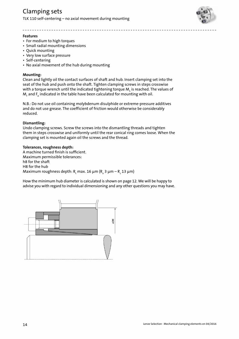
Clamping setsTLK 110 self-centering – no axial movement during mounting

15Lenze Selection · Mechanical clamping elements en 04/2016
Clamping setsTLK 110 self-centering – no axial movement during mounting
Dimensions Torque Axial force Surface pressure on Clamping screws Weight
Shaft Hub Number DIN 912
12.9
Tightening torque
dxD [mm]
L1 [mm]
L2 [mm]
B [mm]
D1 [mm]
MT
[Nm]F
A
[kN]p
W
[N/mm²]p
N
[N/mm²]Number x
typeM
S
[Nm][kg]
6 x 14 9 21 24 25 16 6 277 119 4 x M3 2 0.047 x 15 12 25 29 27 25 7 234 109 3 x M4 5 0.068 x 15 12 25 29 27 29 7 204 109 3 x M4 5 0.059 x 16 14 26 30 28 44 10 208 117 4 x M4 5 0.06
10 x 16 14 26 30 28 49 10 187 117 4 x M4 5 0.0611 x 18 14 26 30 32 53 10 170 104 4 x M4 5 0.0712 x 18 14 26 30 32 58 10 156 104 4 x M4 5 0.0713 x 23 14 26 30 38 63 10 144 81 4 x M4 5 0.1114 x 23 14 26 30 38 68 10 134 81 4 x M4 5 0.115 x 23* 14 30 35 39 120 16 204 133 4 x M5 10 0.1415 x 24 16 36 42 44 170 23 251 157 4 x M6 17 0.2216 x 24 16 36 42 44 180 23 236 157 4 x M6 17 0.2217 x 26 18 38 44 47 190 23 197 129 4 x M6 17 0.2518 x 26 18 38 44 47 200 23 186 129 4 x M6 17 0.2419 x 27 18 38 44 49 210 23 176 124 4 x M6 17 0.2619 x 28* 18 38 43 49 150 16 125 85 4 x M5 10 0.2720 x 28 18 38 44 50 220 23 168 120 4 x M6 17 0.2722 x 32 25 45 51 54 250 23 110 75 4 x M6 17 0.3424 x 34 25 45 51 56 270 23 101 71 4 x M6 17 0.3625 x 34 25 45 51 56 280 23 97 71 4 x M6 17 0.3528 x 39 25 45 51 61 475 34 129 93 6 x M6 17 0.4830 x 41 25 45 51 62 510 34 121 88 6 x M6 17 0.4832 x 43 25 45 51 65 720 45 151 112 8 x M6 17 0.4735 x 47 30 50 56 69 790 45 115 86 8 x M6 17 0.5838 x 50 30 50 56 72 860 45 106 80 8 x M6 17 0.6140 x 53 30 50 56 75 900 45 101 76 8 x M6 17 0.6842 x 55 32 52 60 78 1,750 84 166 127 8 x M8 41 0.7645 x 59 40 65 73 85 1,890 84 124 94 8 x M8 41 1.248 x 62 45 70 78 87 2,010 84 103 80 8 x M8 41 1.250 x 65 45 70 78 92 2,600 105 124 95 10 x M8 41 1.455 x 71 50 75 83 98 2,850 105 101 79 10 x M8 41 1.660 x 77 50 75 83 104 3,150 105 93 72 10 x M8 41 1.865 x 84 50 75 83 111 3,400 105 86 66 10 x M8 41 2.170 x 90 60 91 101 119 5,800 167 105 82 10 x M10 83 375 x 95 60 91 101 126 6,200 167 98 78 10 x M10 83 3
80 x 100 65 96 106 131 8,000 200 102 82 12 x M10 83 3.585 x 10⁶ 65 96 106 137 8,500 200 96 77 12 x M10 83 3.690 x 112 65 96 106 144 11,250 250 113 91 15 x M10 83 3.995 x 120 65 96 106 149 11,850 250 107 85 15 x M10 83 4.4
100 x 125 65 96 106 154 15,000 300 123 98 18 x M10 83 4.6110 x 140 90 128 140 180 16,000 291 78 61 12 x M12 145 8.7120 x 155 90 128 140 198 17,500 291 72 55 12 x M12 145 10.6130 x 165 90 128 140 208 25,000 389 88 69 16 x M12 145 11.3
* Special designs.Other sizes and individual versions on request.

16 Lenze Selection · Mechanical clamping elements en 04/2016
Features• For high torques• Quick mounting• Outstanding perpendicularity of shaft/hub• TLK 130/131 are self-centering• In the case of the TLK 131, there is no axial movement of the hub during mounting
Mounting: Clean and lightly oil the contact surfaces of shaft and hub. Insert clamping set into the seat of the hub and push onto the shaft. Tighten clamping screws in steps crosswise with a torque wrench until the indicated tightening torque M
S is reached. The values of
MT and F
A indicated in the table have been calculated for mounting with oil.
N.B.: Do not use oil containing molybdenum disulphide or extreme-pressure additives and do not use grease. The coefficient of friction would otherwise be considerably reduced.
Dismantling:Undo clamping screws. Screw the screws into the dismantling threads and tighten them in steps crosswise and uniformly until the rear conical ring comes loose. When the clamping set is mounted again, oil the screws and the thread.
Tolerances, roughness depth: A machine turned finish is sufficient.Maximum permissible tolerances: h8 for the shaft H8 for the hub Maximum roughness depth: R
t max. 16 µm (R
a 3 µm – R
z 13 µm)
How the minimum hub diameter is calculated is shown on page 12. We will be happy to advise you with regard to individual dimensioning and any other questions you may have.
Clamping setsTLK 130 self-centering – axial movement during mounting TLK 131 self-centering – no axial movement during mounting

17Lenze Selection · Mechanical clamping elements en 04/2016
Clamping setsTLK 130 self-centering – axial movement during mounting
TLK 131 self-centering – no axial movement during mounting
DimensionsOnly TLK 131
Clamping screwsTLK 130 TLK 131
Torque Axial force
Surface pressure on
Weight Torque Axial force
Surface pressure on
WeightNumber DIN 912
12.9
Tightening torque Shaft Hub Shaft Hub
dxD [mm]
L1 [mm]
L2 [mm]
L3 [mm]
B [mm]
D1 [mm]
Number x type
MS
[Nm]M
T[Nm]
FA
[kN]p
W[N/mm2]
pN
[N/mm2] [kg] MT
[Nm]F
A[kN]
pW
[N/mm2]p
N[N/mm2] [kg]
18 x 47 26 30 41 47 53 6 x M6 17 490 55 310 119 0.4 300 34 193 74 0.519 x 47 26 30 41 47 53 6 x M6 17 510 55 294 119 0.4 320 34 183 74 0.520 x 47 26 30 41 47 53 6 x M6 17 540 55 279 119 0.4 340 34 174 74 0.522 x 47 26 30 41 47 53 6 x M6 17 600 55 254 119 0.4 370 34 158 74 0.524 x 50 26 30 41 47 56 6 x M6 17 650 55 233 112 0.4 400 34 145 70 0.525 x 50 26 30 41 47 56 6 x M6 17 680 55 223 112 0.4 420 34 139 70 0.528 x 55 26 30 41 47 61 6 x M6 17 760 55 199 102 0.5 470 34 124 63 0.630 x 55 26 30 41 47 61 6 x M6 17 820 55 186 102 0.5 510 34 116 63 0.632 x 60 26 30 41 47 66 8 x M6 17 1.160 73 233 124 0.6 720 45 145 77 0.735 x 60 26 30 41 47 66 8 x M6 17 1.270 73 213 124 0.5 790 45 133 77 0.638 x 65 26 30 41 47 71 8 x M6 17 1.380 73 196 115 0.6 860 45 122 71 0.840 x 65 26 30 41 47 71 8 x M6 17 1,450 73 186 115 0.6 900 45 116 71 0.642 x 75 30 35 49 57 81 6 x M8 41 2,120 101 213 119 1 1,320 63 133 74 1.245 x 75 30 35 49 57 81 6 x M8 41 2,270 101 199 119 1 1,410 63 124 74 1.148 x 80 30 35 49 57 86 8 x M8 41 3,230 135 248 149 1.1 2,010 84 155 93 1.350 x 80 30 35 49 57 86 8 x M8 41 3,370 135 238 149 1 2,100 84 149 93 1.155 x 85 30 35 49 57 91 8 x M8 41 3,700 135 217 140 1.1 2,310 84 135 87 1.260 x 90 30 35 49 57 96 8 x M8 41 4,040 135 199 132 1.2 2,520 84 124 83 1.365 x 95 30 35 49 57 101 8 x M8 41 4,380 135 183 125 1.3 2,730 84 114 78 1.4
70 x 110 40 45 59 69 117 8 x M10 83 7,490 214 203 129 2.2 4,670 133 126 80 2.575 x 115 40 45 59 69 122 8 x M10 83 8,020 214 189 123 2.5 5,000 133 118 77 2.680 x 120 40 45 59 69 127 8 x M10 83 8,560 214 177 118 2.6 5,330 133 111 74 2.885 x 125 40 45 59 69 132 10 x M10 83 11.370 268 209 142 2.8 7,080 167 130 88 2.890 x 130 40 45 59 69 137 10 x M10 83 12,040 268 197 136 2.7 7,500 167 123 85 395 x 135 40 45 59 69 142 10 x M10 83 12,700 268 187 131 2.9 7,920 167 116 82 3
100 x 145 46 52 68 80 153 8 x M12 145 15,580 312 180 124 3.9 9,710 194 112 77 4.5110 x 155 46 52 68 80 163 8 x M12 145 17.140 312 163 116 4.2 10,680 194 102 72 4.8120 x 165 46 52 68 80 173 10 x M12 145 23,370 390 187 136 4.8 14,570 243 117 85 5.5130 x 180 46 52 68 80 188 12 x M12 145 30,380 467 207 150 5 18,940 291 129 93 6140 x 190 50 57 76 90 199 10 x M14 230 37.410 535 203 149 6.5 23,300 333 126 93 7.5150 x 200 50 57 76 90 209 12 x M14 230 48,100 641 227 170 7 30,000 400 141 106 7.7160 x 210 50 57 76 90 219 12 x M14 230 51,300 641 213 162 7 32,000 400 133 101 8170 x 225 50 57 76 90 234 14 x M14 230 63,600 748 234 176 8,5 39,650 467 146 110 9.8180 x 235 50 57 76 90 244 14 x M14 230 67,350 748 221 169 9 42,000 467 138 105 9.8190 x 250 50 57 76 90 259 15 x M14 230 76,150 802 224 170 10.5 47,500 500 140 106 11.4200 x 260 50 57 76 90 269 16 x M14 230 85,500 855 227 175 10.5 53,300 533 141 109 11.4210 x 270 50 57 76 90 279 16 x M14 230 89,800 855 216 168 11 56,000 533 135 105 11.8220 x 285 64 72 94 110 294 12 x M16 355 98,050 891 168 130 16.5 61,150 556 105 81 17.5240 x 305 64 72 94 110 314 15 x M16 355 133,700 1114 192 151 18 83,350 695 120 94 18.9
Other sizes, inch dimensions and individual versions on request. N.B.: It is possible to reduce the screw tightening torque MS to
60 % of the value indicated on the dimension sheet. The values of MT, F
A, p
W and p
N then decrease proportionally.

18 Lenze Selection · Mechanical clamping elements en 04/2016
Features• For medium to high torques• Quick mounting• Interchangeable with TLK 200• TLK 132/133 are self-centering• In the case of the TLK 133, there is no axial movement of the hub during mounting
Mounting: Clean and lightly oil the contact surfaces of shaft and hub. Insert clamping set into the seat of the hub and push onto the shaft. Tighten clamping screws in steps crosswise with a torque wrench until the indicated tightening torque M
S is reached. The values of
MT and F
A indicated in the table have been calculated for mounting with oil.
N.B.: Do not use oil containing molybdenum disulphide or extreme-pressure additives and do not use grease. The coefficient of friction would otherwise be considerably reduced.
Dismantling:Undo clamping screws. Screw the screws into the dismantling threads and tighten them in steps crosswise and uniformly until the rear conical ring comes loose. When the clamping set is mounted again, oil the screws and the thread.
Tolerances, roughness depth: A machine turned finish is sufficient.Maximum permissible tolerances: h8 for the shaft H8 for the hub Maximum roughness depth: R
t max. 16 µm (R
a 3 µm – R
z 13 µm)
How the minimum hub diameter is calculated is shown on page 12. We will be happy to advise you with regard to individual dimensioning and any other questions you may have.
Clamping setsTLK 132 self-centering – axial movement during mounting TLK 133 self-centering – no axial movement during mounting

19Lenze Selection · Mechanical clamping elements en 04/2016
Clamping setsTLK 132 self-centering – axial movement during mounting
TLK 133 self-centering – no axial movement during mounting
Other sizes, inch dimensions and individual versions on request. N.B.: It is possible to reduce the screw tightening torque MS to
60 % of the value indicated on the dimension sheet. The values of MT, F
A, p
W and p
N then decrease proportionally.
DimensionsOnly TLK 133
Clamping screwsTLK 132 TLK 133
Torque Axial force
Surfacepressure on
Weight Torque Axial force
Axial force
WeightNumber DIN 912
12.9
Tightening torque Shaft Hub Shaft Hub
dxD [mm]
L1 [mm]
L2 [mm]
L3 [mm]
B [mm]
D1 [mm]
Number x type
MS
TLK132 [Nm]
MS
TLK133 [Nm]
MT
[Nm]F
A[kN]
pW
[N/mm2]p
N[N/mm2] [kg] M
T[Nm]
FA
[kN]p
W[N/mm2]
pN
[N/mm2] [kg]
18 x 47 17 22 28 34 53 5 x M6 14 17 330 38 326 125 0.35 250 28 246 94 0.319 x 47 17 22 28 34 53 5 x M6 14 17 350 38 308 125 0.3 270 28 233 94 0.320 x 47 17 22 28 34 53 6 x M6 14 17 450 45 352 150 0.3 340 34 266 113 0.322 x 47 17 22 28 34 53 6 x M6 14 17 490 45 320 150 0.3 370 34 242 113 0.324 x 50 17 22 28 34 56 6 x M6 14 17 540 45 293 141 0.3 400 34 222 106 0.325 x 50 17 22 28 34 56 6 x M6 14 17 560 45 281 141 0.3 420 34 213 106 0.328 x 55 17 22 28 34 61 6 x M6 14 17 630 45 251 128 0.4 470 34 190 97 0.430 x 55 17 22 28 34 61 6 x M6 14 17 670 45 234 128 0.3 510 34 177 97 0.432 x 60 17 22 28 34 67 8 x M6 14 17 960 60 293 156 0.4 720 45 222 118 0.435 x 60 17 22 28 34 67 8 x M6 14 17 1,050 60 268 156 0.4 790 45 203 118 0.438 x 65 17 22 28 34 72 8 x M6 14 17 1,140 60 247 144 0.4 860 45 187 109 0.540 x 65 17 22 28 34 72 8 x M6 14 17 1,200 60 234 144 0.4 900 45 177 109 0.542 x 75 20 25 33 41 82 8 x M8 35 41 2,410 115 363 204 0.8 1,760 84 265 149 0.845 x 75 20 25 33 41 82 8 x M8 35 41 2,580 115 339 204 0.6 1,890 84 248 149 0.748 x 80 20 25 33 41 87 8 x M8 35 41 2,760 115 318 191 0.8 2,010 84 232 139 0.850 x 80 20 25 33 41 87 8 x M8 35 41 2,870 115 305 191 0.8 2,100 84 223 139 0.855 x 85 20 25 33 41 92 8 x M8 35 41 3,160 115 278 180 0.8 2,310 84 203 131 0.960 x 90 20 25 33 41 97 8 x M8 35 41 3,450 115 254 170 0.8 2,520 84 186 124 0.965 x 95 20 25 33 41 102 9 x M8 35 41 4,200 129 264 181 0.9 3,070 95 193 132 1
70 x 110 24 30 40 50 117 8 x M10 70 83 6,300 181 285 181 1.8 4,670 133 211 134 1.975 x 115 24 30 40 50 122 8 x M10 70 83 6,750 181 266 173 1.8 5,000 133 197 128 280 x 120 24 30 40 50 127 8 x M10 70 83 7,200 181 249 166 1.8 5,330 133 184 123 285 x 125 24 30 40 50 132 10 x M10 70 83 9,600 226 293 200 2 7,080 167 217 147 290 x 130 24 30 40 50 137 10 x M10 70 83 10,150 226 277 192 2.1 7,500 167 205 142 2.295 x 135 24 30 40 50 142 10 x M10 70 83 10,700 226 263 185 2.1 7,920 167 194 137 2.3
100 x 145 26 32 44 56 152 8 x M12 125 145 13,450 269 274 189 2.8 9,710 194 198 137 3110 x 155 26 32 44 56 162 8 x M12 125 145 14,750 269 249 177 3 10,700 194 180 128 3.2120 x 165 26 32 44 56 172 9 x M12 125 145 18,150 302 257 187 3.2 13,100 219 186 135 3.4130 x 180 34 40 54 66 187 12 x M12 125 145 26,200 403 242 175 4.8 18,950 291 175 126 5.2140 x 190 34 40 54 68 197 9 x M14 190 230 27,800 397 221 163 5.2 21,000 300 167 123 5.4150 x 200 34 40 54 68 207 10 x M14 190 230 33,100 442 230 172 5.4 25,000 333 173 130 5.7160 x 210 34 40 54 68 217 12 x M14 190 230 42,400 530 258 197 5.7 32,000 400 195 149 6170 x 225 44 50 64 78 232 12 x M14 190 230 45,050 530 188 142 8 34,000 400 142 107 8.3180 x 235 44 50 64 78 242 12 x M14 190 230 47,700 530 177 136 8.3 36,000 400 134 103 8.8190 x 250 44 50 64 78 257 15 x M14 190 230 62,900 662 210 160 9.6 47,500 500 159 121 10200 x 260 44 50 64 78 267 15 x M14 190 230 66,250 662 200 154 10 50,000 500 151 116 10.5

20 Lenze Selection · Mechanical clamping elements en 04/2016
Features• For medium to high torques• The same hub diameters can be clamped onto different shaft diameters• Quick mounting• Self-centering• No axial displacement of the hub during mounting
Mounting: Clean and lightly oil the contact surfaces of shaft and hub. Insert clamping set into the seat of the hub and push onto the shaft. Tighten clamping screws in steps crosswise with a torque wrench until the indicated tightening torque M
S is reached. The values of
MT and F
A indicated in the table have been calculated for mounting with oil.
N.B.: Do not use oil containing molybdenum disulphide or extreme-pressure additives and do not use grease. The coefficient of friction would otherwise be considerably reduced.
Dismantling:Undo clamping screws. Screw the screws into the dismantling threads and tighten them in steps crosswise and uniformly until the rear conical ring comes loose. When the clamping set is mounted again, oil the screws and the thread.
Tolerances, roughness depth: A machine turned finish is sufficient.Maximum permissible tolerances: h8 for the shaft H8 for the hub Maximum roughness depth: R
t max. 16 µm (R
a 3 µm – R
z 13 µm)
How the minimum hub diameter is calculated is shown on page 12. We will be happy to advise you with regard to individual dimensioning and any other questions you may have.
Clamping setsTLK 134 self-centering – no axial movement during mounting

21Lenze Selection · Mechanical clamping elements en 04/2016
Clamping setsTLK 134 self-centering – no axial movement during mounting
Other sizes, inch dimensions and individual versions on request. N.B.: It is possible to reduce the screw tightening torque MS to
60 % of the value indicated on the dimension sheet. The values of MT, F
A, p
W and p
N then decrease proportionally.
Dimensions Torque Axial force
Surface pressure on Clamping screws Weight
Shaft Hub Number DIN 912
12.9
Tightening torque
dxD [mm]
L1 [mm]
L2 [mm]
L3 [mm]
B [mm]
D1 [mm]
MT
[Nm]F
A
[kN]p
W
[N/mm²]p
N
[N/mm²]Number x
typeM
S
[Nm][kg]
14 x 55 17 22 30 38 62 290 42 468 119 4 x M8 41 0.516 x 55 17 22 30 38 62 340 42 410 119 4 x M8 41 0.518 x 55 17 22 30 38 62 380 42 364 119 4 x M8 41 0.519 x 55 17 22 30 38 62 400 42 345 119 4 x M8 41 0.520 x 55 17 22 30 38 62 420 42 328 119 4 x M8 41 0.522 x 55 17 22 30 38 62 460 42 298 119 4 x M8 41 0.524 x 55 17 22 30 38 62 500 42 273 119 4 x M8 41 0.525 x 55 17 22 30 38 62 530 42 262 119 4 x M8 41 0.528 x 55 17 22 30 38 62 590 42 234 119 4 x M8 41 0.430 x 55 17 22 30 38 62 630 42 219 119 4 x M8 41 0.424 x 65 17 22 30 38 72 630 53 342 126 5 x M8 41 0.725 x 65 17 22 30 38 72 660 53 328 126 5 x M8 41 0.728 x 65 17 22 30 38 72 740 53 293 126 5 x M8 41 0.630 x 65 17 22 30 38 72 790 53 273 126 5 x M8 41 0.632 x 65 17 22 30 38 72 840 53 256 126 5 x M8 41 0.635 x 65 17 22 30 38 72 920 53 234 126 5 x M8 41 0.538 x 65 17 22 30 38 72 1,000 53 216 126 5 x M8 41 0.540 x 65 17 22 30 38 72 1,050 53 205 126 5 x M8 41 0.530 x 80 20 25 33 41 87 1,100 74 325 122 7 x M8 41 132 x 80 20 25 33 41 87 1,180 74 305 122 7 x M8 41 135 x 80 20 25 33 41 87 1,290 74 279 122 7 x M8 41 138 x 80 20 25 33 41 87 1,400 74 257 122 7 x M8 41 140 x 80 20 25 33 41 87 1,470 74 244 122 7 x M8 41 0.942 x 80 20 25 33 41 87 1,540 74 232 122 7 x M8 41 0.945 x 80 20 25 33 41 87 1,650 74 217 122 7 x M8 41 0.948 x 80 20 25 33 41 87 1,760 74 203 122 7 x M8 41 0.950 x 80 20 25 33 41 87 1,840 74 195 122 7 x M8 41 0.9

22 Lenze Selection · Mechanical clamping elements en 04/2016
Features• For low to medium torques• Quick mounting• Self-centering• With axial displacement of the hub during mounting
Mounting: Clean and lightly oil the contact surfaces of shaft and hub. Insert clamping set into the seat of the hub and push onto the shaft. Tighten clamping screws in steps crosswise with a torque wrench until the indicated tightening torque M
S is reached. The values of
MT and F
A indicated in the table have been calculated for mounting with oil.
N.B.: Do not use oil containing molybdenum disulphide or extreme-pressure additives and do not use grease. The coefficient of friction would otherwise be considerably reduced.
Dismantling: Undo clamping screws. Screw the screws into the dismantling threads and tighten them in steps crosswise and uniformly until the rear conical ring comes loose. When the clamping set is mounted again, oil the screws and the thread.
Tolerances, roughness depth: A machine turned finish is sufficient.Maximum permissible tolerances: h8 for the shaft H8 for the hub Maximum roughness depth: R
t max. 16 µm (R
a 3 µm – R
z 13 µm)
How the minimum hub diameter is calculated is shown on page 12. We will be happy to advise you with regard to individual dimensioning and any other questions you may have.
Clamping setsTLK 139 self-centering – axial movement during mounting

23Lenze Selection · Mechanical clamping elements en 04/2016
Clamping setsTLK 139 self-centering – axial movement during mounting
Other sizes, inch dimensions and individual versions on request. N.B.: It is possible to reduce the screw tightening torque MS to
60 % of the value indicated on the dimension sheet. The values of MT, F
A, p
W and p
N then decrease proportionally.
Dimensions Torque Axial force Surface pressure on Clamping screws Weight
Shaft Hub Number DIN 912
12.9
Tightening torque
dxD [mm]
L1 [mm]
L2 [mm]
L3 [mm]
B [mm]
MT
[Nm]F
A
[kN]p
W
[N/mm²]p
N
[N/mm²]Number x
typeM
S
[Nm][kg]
18 x 40 12 15 20 24 210 23.7 233 131 6 x M4 5 0.219 x 41 12 15 20 24 220 23.7 221 128 6 x M4 5 0.220 x 42 12 15 20 24 270 27.7 245 146 7 x M4 5 0.222 x 44 12 15 20 24 300 27.7 223 139 7 x M4 5 0.224 x 46 12 15 20 24 330 27.7 204 133 7 x M4 5 0.225 x 47 12 15 20 24 340 27.7 196 130 7 x M4 5 0.228 x 50 12 15 20 24 500 35.6 225 157 9 x M4 5 0.230 x 52 12 15 20 24 530 35.6 210 151 9 x M4 5 0.232 x 54 12 15 20 24 570 35.6 197 146 9 x M4 5 0.235 x 57 16 19 24 28 690 39.5 158 115 10 x M4 5 0.336 x 58 16 19 24 28 710 39.5 153 113 10 x M4 5 0.338 x 60 16 19 24 28 830 43.5 160 120 11 x M4 5 0.340 x 62 16 19 24 28 870 43.5 152 116 11 x M4 5 0.442 x 70 19 23 30 36 1,530 73 200 146 8 x M6 17 0.645 x 73 19 23 30 36 1,640 73 187 140 8 x M6 17 0.648 x 76 19 23 30 36 1,750 73 175 134 8 x M6 17 0.650 x 78 19 23 30 36 1,820 73 168 131 8 x M6 17 0.655 x 83 19 23 30 36 2,000 73 153 123 8 x M6 17 0.756 x 84 19 23 30 36 2,040 73 150 121 8 x M6 17 0.760 x 88 19 23 30 36 2,460 82.1 158 130 9 x M6 17 0.763 x 91 19 23 30 36 2,580 82.1 150 126 9 x M6 17 0.965 x 93 19 23 30 36 2,660 82.1 146 123 9 x M6 17 1
70 x 105 23 28 37 45 4,720 134.8 183 148 8 x M8 41 1.575 x 110 23 28 37 45 5,050 134.8 170 141 8 x M8 41 1.580 x 115 23 28 37 45 5,390 134.8 160 135 8 x M8 41 1.785 x 120 23 28 37 45 5,730 134.8 150 130 8 x M8 41 290 x 125 23 28 37 45 7,580 168.5 177 156 10 x M8 41 2.3

24 Lenze Selection · Mechanical clamping elements en 04/2016
Features• For medium to high torques• Allows higher tolerances in the case of the shaft and hub• Not self-centering• No axial movement of the hub during mounting
Mounting: Clean and lightly oil the contact surfaces of shaft and hub. Insert clamping set into the seat of the hub and push onto the shaft. Tighten clamping screws in steps crosswise with a torque wrench until the indicated tightening torque M
S is reached. The values of
MT and F
A indicated in the table have been calculated for mounting with oil.
N.B.: Do not use oil containing molybdenum disulphide or extreme-pressure additives and do not use grease. The coefficient of friction would otherwise be considerably reduced.
Dismantling: Undo clamping screws. The clamping set usually comes off automatically. Otherwise, tap lightly with a hammer on the screw heads in order to release the rear conical ring.
Tolerances, roughness depth: A machine turned finish is sufficient.Maximum permissible tolerances: h11 for the shaft H11 for the hub Maximum roughness depth: R
t max. 16 µm (R
a 3 µm – R
z 13 µm)
How the minimum hub diameter is calculated is shown on page 12. We will be happy to advise you with regard to individual dimensioning and any other questions you may have.
Clamping setsTLK 200 not self-centering – no axial movement during mounting

25Lenze Selection · Mechanical clamping elements en 04/2016
Clamping setsTLK 200 not self-centering – no axial movement during mounting
Other sizes and individual versions on request.
Dimensions Torque Axial force Surface pressure on Clamping screws Weight
Shaft Hub Number DIN 912
12.9
Tightening torque
dxD [mm]
L1 [mm]
L2 [mm]
B [mm]
MT
[Nm]F
A
[kN]p
W
[N/mm²]p
N
[N/mm²]Number x
typeM
S
[Nm][kg]
17 x 47 17 20 26 300 35 325 115 8 x M6 17 0.218 x 47 17 20 26 310 35 305 115 8 x M6 17 0.219 x 47 17 20 26 330 35 290 115 8 x M6 17 0.220 x 47 17 20 26 350 35 275 115 8 x M6 17 0.222 x 47 17 20 26 380 35 250 115 8 x M6 17 0.224 x 50 17 20 26 420 35 230 110 8 x M6 17 0.325 x 50 17 20 26 440 35 220 110 8 x M6 17 0.328 x 55 17 20 26 610 44 245 125 10 x M6 17 0.330 x 55 17 20 26 660 44 230 125 10 x M6 17 0.332 x 60 17 20 26 840 53 260 140 12 x M6 17 0.335 x 60 17 20 26 920 53 235 140 12 x M6 17 0.338 x 65 17 20 26 1.170 62 255 150 14 x M6 17 0.440 x 65 17 20 26 1,230 62 240 150 14 x M6 17 0.342 x 75 20 24 32 2,050 98 310 175 12 x M8 41 0.645 x 75 20 24 32 2,200 98 290 175 12 x M8 41 0.648 x 80 20 24 32 2,340 98 270 160 12 x M8 41 0.650 x 80 20 24 32 2,440 98 260 160 12 x M8 41 0.655 x 85 20 24 32 3,140 114 275 180 14 x M8 41 0.660 x 90 20 24 32 3,420 114 255 170 14 x M8 41 0.765 x 95 20 24 32 4,240 131 265 180 16 x M8 41 0.7
70 x 110 24 28 38 6.340 181 285 180 14 x M10 83 1.375 x 115 24 28 38 6,800 181 265 175 14 x M10 83 1.380 x 120 24 28 38 7,250 181 250 165 14 x M10 83 1.485 x 125 24 28 38 8,810 207 270 185 16 x M10 83 1.490 x 130 24 28 38 9,320 207 255 175 16 x M10 83 1.595 x 135 24 28 38 11,070 233 270 190 18 x M10 83 1.6
100 x 145 26 33 45 13,200 264 270 185 14 x M12 145 2.2110 x 155 26 33 45 14,500 264 245 175 14 x M12 145 2.5120 x 165 26 33 45 18,100 302 255 185 16 x M12 145 2.6130 x 180 34 38 50 24,500 377 225 165 20 x M12 145 3.8140 x 190 34 38 50 29,000 415 230 170 22 x M12 145 3.9150 x 200 34 38 50 33,900 453 235 175 24 x M12 145 4160 x 210 34 38 50 39,200 490 240 180 26 x M12 145 4.3170 x 225 38 44 58 48,400 569 235 175 22 x M14 230 5.8180 x 235 38 44 58 55,900 621 240 185 24 x M14 230 6190 x 250 46 52 66 68,800 725 220 165 28 x M14 230 8.5200 x 260 46 52 66 77,600 776 225 170 30 x M14 230 8.6220 x 285 50 56 72 102,800 935 225 175 26 x M16 300 11240 x 305 50 56 72 129,500 1,079 240 190 30 x M16 300 12260 x 325 50 56 72 159,000 1,223 250 200 34 x M16 300 13280 x 355 60 66 84 193,900 1,385 220 170 32 x M18 410 19300 x 375 60 66 84 233,700 1,558 230 185 36 x M18 410 20320 x 405 72 78 98 323,400 2.021 235 185 36 x M20 590 30340 x 425 72 78 98 343,600 2,021 220 175 36 xM20 590 30360 x 455 84 90 112 452,900 2,516 220 175 36 xM22 790 42380 x 475 84 90 112 478,100 2,516 210 165 36 xM22 790 44400 x 495 84 90 112 503,200 2,516 200 160 36 xM22 790 46420 x 515 84 90 112 587,100 2,796 210 170 40 x M22 790 50440 x 545 96 102 126 710,300 3,229 205 165 40 x M24 1,000 65460 x 565 96 102 126 742,600 3,229 195 160 40 x M24 1,000 67480 x 585 96 102 126 813,600 3,390 195 160 42 x M24 1,000 71500 x 605 96 102 126 887,900 3,552 192 160 44 x M24 1,000 73520 x 630 96 102 126 944,400 3,632 195 160 45 x M24 1.000 80540 x 650 96 102 126 980,700 3.632 185 155 45 x M24 1,000 82560 x 670 96 102 126 1,084,800 3,875 190 160 48 x M24 1.000 85580 x 690 96 102 126 1,170,400 4.036 190 160 50 x M24 1.000 88600 x 710 96 102 126 1,210,800 4.036 185 155 50 x M24 1,000 91620 x 730 96 102 126 1,301,200 4,197 185 160 52 x M24 1.000 93640 x 750 96 102 126 1,394,800 4,359 190 160 54 x M24 1,000 96660 x 770 96 102 126 1,491,700 4,520 190 160 56 x M24 1,000 99680 x 790 96 102 126 1,536,900 4,520 185 160 56 x M24 1,000 102700 x 810 96 102 126 1,695,100 4.843 190 165 60 x M24 1.000 104720 x 830 96 102 126 1,743,500 4.843 185 160 60 x M24 1,000 107740 x 850 96 102 126 1,851,700 5,005 185 165 62 x M24 1.000 110760 x 870 96 102 126 1,963,100 5,166 190 165 64 x M24 1,000 113780 x 890 96 102 126 2,046,200 5,247 185 165 65 x M24 1,000 116800 x 910 96 102 126 2,131,000 5,327 185 160 66 x M24 1,000 118

26 Lenze Selection · Mechanical clamping elements en 04/2016
Features• For low to medium torques• Quick mounting• Small radial mounting dimensions• TLK 250 not self-centering / TLK 250L self-centering• In the case of the TLK 250/TLK 250L, the hub shows axial movement during mounting
Mounting: Clean and lightly oil the contact surfaces of shaft and hub. Insert clamping set into the seat of the hub and push onto the shaft. Tighten the groove nut until the indicated tightening torque M
S is reached and fold down the security washer tooth if fitted. The
values of MT and F
A indicated in the table have been calculated for mounting with oil.
N.B.: Do not use oil containing molybdenum disulphide or extreme-pressure additives and do not use grease. The coefficient of friction would otherwise be considerably reduced.
Dismantling:Undo groove nut. The cone angle of the TLK 250 is around 17°. The clamping set therefore usually comes off automatically. The TLK 250L has a self-locking cone angle and is therefore more difficult to remove. We recommend use of the TLK 250.
Tolerances, roughness depth: A machine turned finish is sufficient.Maximum permissible tolerances: h8 for the shaft H8 for the hub Maximum roughness depth: R
t max. 16 µm (R
a 3 µm – R
z 13 µm)
How the minimum hub diameter is calculated is shown on page 12. We will be happy to advise you with regard to individual dimensioning and any other questions you may have.
Clamping setsTLK 250 not self-centering – axial movement during mounting TLK 250L self-centering – axial movement during mounting

27Lenze Selection · Mechanical clamping elements en 04/2016
Clamping setsTLK 250 not self-centering – axial movement during mounting
TLK 250L self-centering – axial movement during mounting
Dimensions Torque Axial force Surface pressure on Groove nut Weight
Shaft Hub TypeDIN 981
Tightening torque
dxD [mm]
B[mm]
L1 [mm]
D1 [mm]
MT
[Nm]F
A
[kN]p
W
[N/mm²]p
N
[N/mm²]M
S
[Nm][kg]
14 x 25 16.5 6.5 32 38 5 200 110 KM4 95 0.0515 x 25 16.5 6.5 32 41 5 185 110 KM4 95 0.0516 x 25 16.5 6.5 32 43 5 174 110 KM4 95 0.0417 x 30 18 6.5 38 55 6 197 112 KM5 160 0.0818 x 30 18 6.5 38 58 6 186 112 KM5 160 0.0819 x 30 18 6.5 38 62 7 176 112 KM5 160 0.0820 x 30 18 6.5 38 66 7 167 111 KM5 160 0,0722 x 35 18 6.5 45 96 8 202 127 KM6 220 0.124 x 35 18 6.5 45 105 9 185 127 KM6 220 0.0925 x 35 18 6.5 45 110 9 178 127 KM6 220 0.0928 x 40 19.5 7 52 150 10 176 123 KM7 340 0.0730 x 40 19.5 7 52 160 11 164 123 KM7 340 0.0732 x 45 21.5 8 58 210 12 167 120 KM8 480 0.1835 x 45 21.5 8 58 230 13 153 120 KM8 480 0.1736 x 45 21.5 8 58 240 13 149 120 KM8 480 0.1538 x 52 24.5 10 65 290 14 126 93 KM9 680 0.2540 x 52 24.5 10 65 310 15 120 93 KM9 680 0.2442 x 57 25.5 10 70 370 17 131 96 KM10 870 0.345 x 57 25.5 10 70 400 18 122 96 KM10 870 0.2848 x 62 25.5 10 75 500 21 135 105 KM11 970 0.3250 x 62 25.5 10 75 520 21 130 105 KM11 970 0.355 x 68 27.5 12 80 610 22 103 84 KM12 1,100 0.3656 x 68 27.5 12 80 620 22 101 82 KM12 1,100 0.3460 x 73 28.5 12 85 800 27 113 93 KM13 1,300 0.463 x 79 30.5 14 92 980 31 107 86 KM14 1,600 0.5665 x 79 30.5 14 92 1,010 31 104 86 KM14 1,600 0,5270 x 84 31.5 14 98 1,240 35 110 92 KM15 2,000 0.6
Dimensions Torque Axial force Surface pressure on Groove nut Weight
Shaft Hub TypeDIN 981
Tightening torque
dxD [mm]
B[mm]
L1 [mm]
D1 [mm]
MT
[Nm]F
A
[kN]p
W
[N/mm²]p
N
[N/mm²]M
S
[Nm][kg]
14 x 25 30 20 32 64 9 85 45 KM4 95 0.0815 x 25 30 20 32 70 9 80 45 KM4 95 0.0816 x 25 30 20 32 73 9 75 45 KM4 95 0.0717 x 25 32 20 32 80 9 70 45 KM4* 95 0.0718 x 30 32 20 38 100 10 80 45 KM5 160 0.1219 x 30 32 20 38 105 11 75 45 KM5 160 0.1220 x 30 32 20 38 112 11 70 45 KM5 160 0.1122 x 35 36 25 45 163 14 70 45 KM6 220 0.1824 x 35 36 25 45 178 14 65 45 KM6 220 0.1625 x 35 36 25 45 185 14 60 45 KM6 220 0.1528 x 40 42 30 52 250 17 55 40 KM7 340 0.2430 x 40 42 30 52 270 17 50 40 KM7 340 0.2132 x 45 44 30 58 350 21 60 45 KM8 480 0.3235 x 45 44 30 58 390 21 55 45 KM8 480 0.2638 x 50 45 30 65 500 26 60 45 KM9 680 0.3540 x 50 45 30 65 520 26 55 45 KM9 680 0.3342 x 55 46 30 70 630 30 65 50 KM10 870 0.4345 x 55 46 30 70 680 30 60 50 KM10 870 0,3948 x 60 46 30 75 840 35 60 50 KM11 970 0.4550 x 60 46 30 75 880 35 60 50 KM11 970 0.455 x 65 46 30 80 1,030 37 60 50 KM12 1,100 0.4460 x 70 52 30 85 1,360 45 65 55 KM13 1,300 0.55
* Without safety sheet
TLK 250 TLK 250L

28 Lenze Selection · Mechanical clamping elements en 04/2016
Features• For low to medium torques• Quick mounting, small radial mounting dimensions• Not self-centering, with axial movement of the hub during mounting• Slotted version also available as an option.
Mounting: Clean and lightly oil contact surfaces of shaft and hub. Insert clamping elements, spacer ring and clamping flange. Tighten clamping screws in steps crosswise until the indicated tightening torque M
S has been reached. The values of M
T and F
A indicated in the table
have been calculated for mounting with oil. N.B.: Do not use oil containing molybdenum sulphide or extreme-pressure additives, do not use grease. The coefficient of friction would otherwise be considerably reduced.
Removal: Undo and remove all clamping screws. As a rule, the TLK 300 is released automatically. If not, hit the hub lightly with a hammer.
Tolerances, roughness depth: A machine turned finish is sufficient.Maximum permissible tolerances: h6 for the shaft/H7 for hub up to Ø 40 mm; h8 for the shaft/H8 for the hub Ø 42 mm Maximum permissible roughness depth: R
t max. 6 µm (R
a 1 µm – R
z 5 µm)
How the minimum hub diameter is calculated is shown on page 12. We will be happy to advise you with regard to individual dimensioning and any other questions you may have.
Clamping setsTLK 300 not self-centering – axial movement during mounting
DIN912 C=0.140
Total screw force FS
[N] M
S
[Nm]
dg 8.8 10.9 12.9 8.8 10.9 12.9
M4 3,900 5,450 6,550 2.9 4.1 4.9M5 6,350 8,950 10,700 6 9 10M6 9,000 12,600 15,100 10 14 17
[M7] 13,200 18,500 22,200 16 23 28M8 16,500 23,200 27,900 25 35 41
[M9] 22,000 30,900 37,100 36 51 61M10 26,200 36,900 44,300 49 69 83M12 38,300 54,000 64,500 86 120 145M14 52,500 74,000 88,500 135 190 230M16 73,000 102,000 123,000 210 295 355M18 88,000 124,000 148,000 290 405 485M20 114,000 160,000 192,000 410 580 690M22 141,000 199,000 239,000 550 780 930M24 164,000 230,000 276,000 710 1,000 1,200M27 215,000 302,000 363,000 1,050 1,500 1,800M30 262,000 368,000 442,000 1,450 2,000 2,400
Distance between centres of the screws Øl = D + 12 + dg (screws mounted on hub) Distance between centres of the screws Øl = d - 12 - dg (screws mounted on shaft) Flange thickness Sf = dg x 1.3 (screw quality class 8.8) Flange thickness Sf = dg x 1.8 (screw quality class 12.9)
Torque if several clamping sets are used: With one TLK 300: M
T = according to catalogue
With two TLK 300: MT = according to catalogue x 1.55
With three TLK 300: MT = according to catalogue x 1.85
With four TLK 300: MT = according to catalogue x 2.02
FGes
= FS x number of screws
FV = See page 29
Transmittable torque:
MT =
FGES
- FV x 0.12 x
d
0.54 2000

29Lenze Selection · Mechanical clamping elements en 04/2016
Clamping setsTLK 300 not self-centering – axial movement during mounting
Dimensions Preload force
Total force Torque Axial force
Clamping clearancebefore screws are
tightened[mm]
Spacer ring Surface pressure Weight
Inside Outside Shaft Hub
dxD [mm]
B[mm]
L1 [mm]
FV
[N]F
Ges
[N]M
T
[Nm]F
A
[kN]1* 2* 3* 4* d1
[mm]D1
[mm]p
w
[N/mm2]p
N
[N/mm2][kg]
6 x 9 4.5 3.7 - 3,800 2 0.84 2.5 2.5 3 4 6.1 8.9 115 75 0.0027 x 10 4.5 3.7 - 3,900 3 0.86 2.5 2.5 3 4 7.1 9.9 105 70 0.0028 x 11 4.5 3.7 - 5,300 5 1.17 2.5 2.5 3 4 8.1 10.9 120 90 0.0029 x 12 4.5 3.7 7,650 15,600 8 1.76 2.5 2.5 3 4 9.1 11.9 140 105 0.002
10 x 13 4.5 3.7 7,000 15,600 10 1.91 2.5 2.5 3 4 10.1 12.9 135 105 0.00212 x 15 4.5 3.7 7,000 15,600 11 1.91 2.5 2.5 3 4 12.1 14.9 115 90 0.00213 x 16 4.5 3.7 6,500 15,600 13 2.02 2.5 2.5 3 4 13.1 15.9 110 90 0.00214 x 18 6.3 5.3 11,000 25,400 22 3.18 3.5 3.5 4.5 5.5 14.1 17.9 115 90 0.00515 x 19 6.3 5.3 10,800 25,400 24 3.24 3.5 3.5 4.5 5.5 15.1 18.9 110 85 0.00516 x 20 6.3 5.3 10,000 25,400 27 3.42 3.5 3.5 4.5 5.5 16.1 19.9 105 85 0.00617 x 21 6.3 5.3 9,600 25,400 30 3.51 3.5 3.5 4.5 5.5 17.1 20.9 105 85 0.00618 x 22 6.3 5.3 9,150 25,400 32 3.61 3.5 3.5 4.5 5.5 18.1 21.9 100 80 0.00719 x 24 6.3 5.3 12,500 36,000 49 5.22 3.5 3.5 4.5 5.5 19.2 23.8 140 110 0.00720 x 25 6.3 5.3 12,000 36,000 53 5.33 3.5 3.5 4.5 5.5 20.2 24.8 135 105 0.00922 x 26 6.3 5.3 9,000 36,000 66 6 3.5 3.5 4.5 5.5 22,2 25.8 135 115 0.00724 x 28 6.3 5.3 8,400 36,000 73 6.13 3.5 3.5 4.5 5.5 24.2 27.8 130 110 0.00825 x 30 6.3 5.3 10,000 36,000 72 5.77 3.5 3.5 4.5 5.5 25.2 29.8 115 95 0.00928 x 32 6.3 5.3 7,500 36,000 88 6.33 3.5 3.5 4.5 5.5 28.2 31.8 115 100 0.0130 x 35 6.3 5.3 8,600 36,000 91 6.08 3.5 3.5 4.5 5.5 30.2 34.8 100 85 0.01132 x 36 6.3 5.3 7,900 45,000 131 8.24 3.5 3.5 4.5 5.5 32.2 35.8 130 115 0.01135 x 40 7 6 10,000 54,000 171 9.77 3.5 3.5 4.5 5.5 35.2 39.8 125 110 0.01636 x 42 7 6 11,700 54,000 169 9.39 3.5 3.5 4.5 5.5 36.2 41.8 115 100 0.01938 x 44 7 6 11,000 54,000 181 9.55 3.5 3.5 4.5 5.5 38.2 43.8 110 95 0.02140 x 45 8 6.6 13,900 66,000 231 11.57 3.5 4.5 5.5 6.5 40.2 44.8 115 105 0.02142 x 48 8 6.6 15,550 66,000 235 11.22 3.5 4.5 5.5 6.5 42.2 47.8 110 95 0.02645 x 52 10 8.6 28,300 99,000 353 15.71 3.5 4.5 5.5 6.5 45.2 51.8 105 95 0.04548 x 55 10 8.6 24,700 132,000 572 23.84 3.5 4.5 5.5 6.5 48.2 54.8 155 135 0.04350 x 57 10 8.6 23,600 132,000 602 24.08 3.5 4.5 5.5 6.5 50.2 56.8 150 130 0.04555 x 62 10 8.6 21,700 132,000 670 24.35 3.5 4.5 5.5 6.5 55.2 61.8 140 125 0.04956 x 64 12 10.4 29,500 157,200 790 28.2 3.5 4.5 5.5 7 56.2 63.8 130 115 0.0760 x 68 12 10.4 27,500 157,200 860 28.6 3.5 4.5 5.5 7 60.2 67.8 125 110 0.0763 x 71 12 10.4 26,500 157,200 910 28.8 3.5 4.5 5.5 7 63.2 70.8 120 105 0.0865 x 73 12 10.4 25,500 157,200 950 29.2 3.5 4.5 5.5 7 65.2 72.8 115 100 0.0970 x 79 14 12.2 31,000 209,600 1,380 39.4 3.5 5 6.5 7.5 70.3 78.7 125 110 0.11571 x 80 14 12.2 31,000 209,600 1,400 39.4 3.5 5 6.5 7.5 71.3 79.7 120 110 0.1175 x 84 14 12.2 34,700 209,600 1,450 38.6 3.5 5 6.5 7.5 75.3 83.7 115 100 0.1280 x 91 17 15 48,000 290,000 2,200 55 4 6 6.5 8 80.3 90.7 125 105 0.2185 x 96 17 15 45,500 305,000 2,400 56.4 4 6 6.5 8 85.3 95.7 120 105 0.21
90 x 101 17 15 43,600 320,000 2,730 60.5 4 6 6.5 8 90.3 100.7 120 105 0.2295 x 10⁶ 17 15 41,300 330,000 3,050 64.2 4 6 6.5 8 95.3 105.7 120 110 0.23
100 x 114 21 18,7 61,000 445,000 4,200 84 5 6 7 9 100.3 113.7 120 105 0.39110 x 124 21 18.7 66,000 485,000 5,150 93.6 5 6 7 9 110.3 123.7 120 105 0.42120 x 134 21 18,7 60,300 510,000 6,050 100.8 5 6 7 9 120.2 133.7 120 105 0.46130 x 148 28 25.3 96,300 765,000 9,600 147.6 5 7 9 11 130.4 147.6 120 105 0.86140 x 158 28 25.3 89,000 800,500 11,000 158.5 6 7 9 11 140.4 157.6 120 105 0.96150 x 168 28 25.3 85,000 860,000 12,900 172 6 7 8 11 150.4 167.6 120 105 1160 x 178 28 25.3 78,600 900,000 14,600 182.5 6 7 9 11 160.4 177.6 120 110 1170 x 191 33 30 117,400 1,160,000 19,500 229 7 9 10 12 170.5 190.5 120 105 1.54180 x 201 33 30 111,300 1,200,000 21,300 236 7 9 10 12 180.5 200.5 120 105 1.5190 x 211 33 30 105,000 1,260,000 24,200 255 7 9 10 12 190.5 210.5 120 110 1.8200 x 224 38 34.8 134,200 1,550,000 31,000 310 7 8 11 13 200.6 223.4 120 105 2.4210 x 234 38 34.8 127,200 1,610,000 35,000 333 7 9 11 13 210.6 233.4 120 110 2.5220 x 244 38 34.8 122,100 1,690,000 38,000 345 7 9 11 13 220.6 243.4 120 110 2.6230 x 257 43 39.5 164,500 2,000,000 47,000 408 7 10 12 14 230.6 256.4 120 105 3.4240 x 267 43 39.5 157,400 2,250,000 51,000 425 7 10 12 14 240.6 266.4 120 110 3.8250 x 280 48 44 190,000 2,060,000 52,000 415 7 10 13 16 250.8 279.2 100 89 4.8260 x 290 48 44 182,000 2,132,000 56,500 435 7 10 13 16 260.8 289.2 100 89 4.9270 x 300 48 44 177,000 2,207,000 61,000 450 7 10 13 16 270.8 299.2 100 89 5280 x 313 53 49 206,000 2,536,000 72,500 520 7 11 14 17 280.8 312,2 100 89 6.4290 x 323 53 49 222,000 2,632,000 77,500 535 7 11 14 17 290.8 322.2 100 89 6.5300 x 333 53 49 214,000 2,704,000 83,000 555 7 11 14 17 300.8 332.2 100 89 6.8320 x 360 65 59 292,000 3,492,000 114,000 710 10 15 20 25 321 359 100 89 11340 x 380 65 59 272,000 3,672,000 128,500 755 10 15 20 25 341 379 100 89 11.5360 x 400 65 59 258,000 3,858,000 144,000 800 10 15 20 25 361 399 100 90 12.3380 x 420 65 59 269,000 4,069,000 160,500 845 10 15 20 25 381 419 100 90 13400 x 440 65 59 256,000 4,256,000 178,000 890 10 15 20 25 401 439 100 90 13.7420 x 460 65 59 244,000 4,444,000 196,000 935 10 15 20 25 421 459 100 90 14,1440 x 480 65 59 234,000 4,633,000 215,000 980 10 15 20 25 441 479 100 90 14.8460 x 500 65 59 224,000 4,824,000 235.000 1,020 10 15 20 25 461 499 100 91 15.5480 x 520 65 59 239,000 5,039,000 256,000 1,070 10 15 20 25 481 519 100 91 16500 x 540 65 59 229,000 5,229,000 278,000 1,110 10 15 20 25 501 539 100 91 16.7520 x 570 80 73 338,000 6,788,000 372,000 1,430 12 18 24 30 521 569 100 91 27540 x 590 80 73 326,000 7,026,000 400,000 1,480 12 18 24 30 541 589 100 91 28
* Number of clamping elements used.Other sizes and individual versions on request.

30 Lenze Selection · Mechanical clamping elements en 04/2016
Features• For low to medium torques• Quick mounting• Self-centering• With axial movement of the hub during mounting
Mounting: See page 24.
Dismantling: Unscrew and remove clamping screws. Screw screws into the forcing threads and tighten in steps crosswise until the rear conical ring becomes detached. If the clamping set is mounted again, oil the screws and the thread.
Tolerances, roughness depth: A machine turned finish is sufficient.Maximum permissible tolerances: h8 for the shaft H8 for the hub Maximum roughness depth: R
t max. 16 µm (R
a 3 µm – R
z 13 µm)
How the minimum hub diameter is calculated is shown on page 12. We will be happy to advise you with regard to individual dimensioning and any other questions you may have.
Clamping setsTLK 350 self-centering – axial movement during mounting
Dimensions Torque Axial force Surface pressure on Clamping screws Weight
Shaft Hub Number DIN 912
12.9
Tightening torque
dxD [mm]
L1[mm]
L2[mm]
B [mm]
MT
[Nm]F
A
[kN]p
W
[N/mm²]p
N
[N/mm²]Number x
typeM
S
[Nm][kg]
6 x 16 10.5 11 13.5 9 3 184 69 3 x M2.5 1.2 0,0126.35 x 16 10,5 11 13.5 10 3 173 69 3 x M2.5 1.2 0.012
7 x 17 10.5 11 13.5 11 3 157 65 3 x M2.5 1.2 0,0138 x 18 10.5 11 13.5 12 3 138 61 3 x M2.5 1.2 0.0159 x 20 12.5 13 15.5 18 4 138 62 4 x M2.5 1.2 0.02
9.53 x 20 12.5 13 15.5 19 4 130 62 4 x M2.5 1.2 0,0210 x 20 12.5 13 15.5 20 4 124 62 4 x M2.5 1.2 0.01911 x 22 12.5 13 15.5 22 4 113 56 4 x M2.5 1.2 0.02412 x 22 12.5 13 15.5 24 4 104 56 4 x M2.5 1.2 0.02214 x 26 16.5 17 20 42 6 99 53 4 x M3 2.1 0.03915 x 28 16.5 17 20 44 6 93 50 4 x M3 2.1 0.04416 x 32 16.5 17 21 83 10.4 152 76 4 x M4 4.9 0.06717 x 35 20.5 21 25 88 10.4 116 56 4 x M4 4.9 0.0918 x 35 20.5 21 25 93 10.4 109 56 4 x M4 4.9 0.08719 x 35 20.5 21 25 99 10.4 104 56 4 x M4 4.9 0.08320 x 38 20.5 21 26 170 17 161 85 4 x M5 10 0.122 x 40 20.5 21 26 187 17 146 80 4 x M5 10 0.1124 x 47 25 26 32 287 24 153 78 4 x M6 17 0.225 x 47 25 26 32 299 24 147 78 4 x M6 17 0.19
25.4 x 47 25 26 32 304 24 144 78 4 x M6 17 0.1828 x 50 25 26 32 503 36 196 110 6 x M6 17 0.2230 x 55 25 26 32 539 36 183 100 6 x M6 17 0.2732 x 55 25 26 32 575 36 172 100 6 x M6 17 0.2535 x 60 30 31 37 838 48 176 102 8 x M6 17 0.3638 x 65 30 31 37 910 48 162 95 8 x M6 17 0.4340 x 65 30 31 37 958 48 154 95 8 x M6 17 0.442 x 75 35 36 44 1,394 66.3 175 98 6 x M8 41 0.6745 x 75 35 36 44 1,493 66.3 163 98 6 x M8 41 0.6348 x 80 35 36 44 2,124 88.5 204 122 8 x M8 41 0.7450 x 80 35 36 44 2,212 88.5 196 122 8 x M8 41 0.7

31Lenze Selection · Mechanical clamping elements en 04/2016
Clamping setsTLK 400 self-centering – no axial movement during mounting TLK 401 self-centering – no axial movement during mounting
Features• For very high torques• Absorption of bending torques (Please consult our technicians)• Uniform distribution of surface pressure• Self-centering• No axial displacement of the hub during mounting
Mounting: Clean and lightly oil the contact surfaces of shaft and hub. Insert clamping set into seat of hub and push onto the shaft. Tighten clamping screws in steps crosswise and uniformly with a torque wrench until 50% of the indicated tightening torque M
S is
reached. Then repeat the process with the full tightening torque. Starting with the last tightened screw and proceeding in a clockwise direction, check that all the clamping screws have been tightened with the correct tightening torque M
S. This concludes the
mounting process. If the clamping screws are to be capable of being undone manually, they can be pretensioned with 60% of the indicated tightening torque. The values of M
T
and FA indicated in the table have been calculated for mounting with oil.
N.B.: Do not use oil containing molybdenum disulphide or extreme-pressure additives and do not use grease. The coefficient of friction would otherwise be considerably reduced.
Dismantling: Undo and remove clamping screws and insert into the dismantling threads of the front conical ring. Tighten screws in steps crosswise and uniformly with 50% of the tightening torque. Repeat the process with the full tightening torque. When the front conical ring has been released, the screws must be screwed into the intermediate ring and the process for releasing the rear conical ring must be repeated as described above.
Tolerances, roughness depth: A machine turned finish is sufficient.Maximum permissible tolerances: h8 for the shaft H8 for the hub Maximum roughness depth: R
t max. 16 µm (R
a 3 µm – R
z 13 µm)
How the minimum hub diameter is calculated is shown on page 12. We will be happy to advise you with regard to individual dimensioning and any other questions you may have.

32 Lenze Selection · Mechanical clamping elements en 04/2016
Clamping setsTLK 400 self-centering – no axial movement during mounting
Dimensions Clamping screws Torque Axial force Surface pressure Weight
Number DIN 912 12.9
Tightening torque
Shaft Hub
dxD [mm]
L1[mm]
L2[mm]
B [mm]
Number x type
MS
[Nm]M
T
[Nm]F
A
[kN]p
W
[N/mm²]p
N
[N/mm²][kg]
45 x 75 56 64 72 8 x M8 41 3,460 155 165 100 1.348 x 80 56 64 72 8 x M8 41 3,680 155 150 95 1.550 x 80 56 64 72 8 x M8 41 3,820 155 147 95 1.455 x 85 56 64 72 8 x M8 41 4,260 155 135 85 1.560 x 90 56 64 72 10 x M8 41 5,820 190 155 100 1.565 x 95 56 64 72 10 x M8 41 6,270 190 140 95 1.6
70 x 110 70 78 88 10 x M10 83 10.730 305 170 105 375 x 115 70 78 88 10 x M10 83 11.540 305 155 100 3.180 x 120 70 78 88 12 x M10 83 14,700 369 175 115 3.585 x 125 70 78 88 12 x M10 83 15,700 369 165 110 3.590 x 130 70 78 88 12 x M10 83 16,610 370 157 106 3.895 x 135 70 78 88 12 x M10 83 17,530 370 150 102 4
100 x 145 90 100 112 12 x M12 145 26,900 538 160 110 6110 x 155 90 100 112 12 x M12 145 29,530 538 143 102 6.2120 x 165 90 100 112 14 x M12 145 37,610 628 154 112 6.8130 x 180 104 116 130 12 x M14 230 48,000 738 143 106 9.8140 x 190 104 116 130 14 x M14 230 60,290 861 160 117 10.2150 x 200 104 116 130 16 x M14 230 73,800 985 165 125 10.9160 x 210 104 116 130 16 x M14 230 78,770 983 155 118 11.5170 x 225 134 146 162 14 x M16 355 101,730 1,197 140 108 17.2180 x 235 134 146 162 16 x M16 355 123,200 1,369 150 115 18190 x 250 134 146 162 16 x M16 355 129,880 1,368 141 110 21.5200 x 260 134 146 162 16 x M16 355 136,840 1,368 137 104 22220 x 285 134 146 162 20 x M16 355 188,000 1,710 155 120 25240 x 305 134 146 162 22 x M16 355 225,000 1,880 155 120 27260 x 325 134 146 162 22 x M16 355 244,000 1,880 155 115 30280 x 355 165 177 197 20 x M20 690 373,000 2,670 145 120 46300 x 375 165 177 197 22 x M20 690 440,000 2,930 155 125 50320 x 405 165 177 197 22 x M20 690 470,000 2,930 145 115 60340 x 425 165 177 197 24 x M20 690 544,000 3,200 150 120 65360 x 455 190 202 224 22 x M22 930 658,000 3,650 140 110 89380 x 475 190 202 224 26 x M22 930 821,000 4,320 160 130 93400 x 495 190 202 224 26 x M22 930 864,000 4.320 150 120 98
Other sizes, inch dimensions and individual versions on request. N.B. It is possible to reduce the screw tightening torque MS to 60% of the value
indicated on the dimension sheet. The values of MT, F
A, p
W and p
N then decrease proportionally.

33Lenze Selection · Mechanical clamping elements en 04/2016
Clamping setsTLK 401 self-centering – no axial movement during mounting
TLK 401.0 self-centering – no axial movement during mounting
Dimensions
Clamping screws
DIN 912 12.9
TLK 401 TLK 401.0
Tightening torque Torque Axial
force
Surface pressure on Tightening
torque Torque Axial force
Surface pressure on Weight
TLK 401TLK 401.0Shaft Hub Shaft Hub
dxD [mm]
L1 [mm]
L2 [mm]
B [mm]
Number x type
MS
[Nm]M
T
[Nm]F
A[kN]
pW
[N/mm2]p
N[N/mm2]
MS
[Nm]M
T
[Nm]F
A[kN]
pW
[N/mm2]p
N[N/mm2] [kg]
70 x 110 50 58 68 8 x M10 49 5,100 145 112 71 83 8,620 245 190 120 2.375 x 115 50 58 68 8 x M10 49 5.420 145 103 68 83 9,160 245 174 115 2.480 x 120 50 58 68 8 x M10 49 5,820 145 97 65 83 9,840 245 164 110 2.585 x 125 50 58 68 10 x M10 49 7,700 182 114 77 83 13,000 307 193 130 2.690 x 130 50 58 68 10 x M10 49 8,100 182 107 74 83 13,700 307 181 125 2.795 x 135 50 58 68 10 x M10 49 8,600 182 102 72 83 14,540 307 173 122 2.8
100 x 145 60 70 80 10 x M10 49 9,100 182 80 55 83 15,380 307 135 93 4110 x 155 60 70 80 10 x M10 49 10,000 182 75 52 83 16.900 307 127 88 4.5120 x 165 60 70 80 12 x M10 49 13,100 218 80 59 83 22,150 365 135 100 4.8130 x 180 68 80 92 12 x M12 86 20,700 319 95 69 145 34,860 537 160 116 6.3140 x 190 68 80 92 12 x M12 86 22,300 319 89 66 145 37,550 537 150 111 6.6150 x 200 68 80 92 12 x M12 86 23,900 319 83 62 145 40,250 537 140 105 7160 x 210 68 80 92 14 x M12 86 29,800 372 90 69 145 50,180 626 152 116 7.4170 x 225 75 87 99 16 x M12 86 36,200 426 89 67 145 60,960 717 150 113 10180 x 235 75 87 99 16 x M12 86 38,300 426 84 64 145 64,500 717 142 108 11.3190 x 250 88 100 112 18 x M12 86 45,500 479 76 58 145 76,620 806 128 98 14200 x 260 88 100 112 18 x M12 86 47,900 479 72 56 145 80,660 806 122 95 15.2220 x 285 98 110 124 14 x M14 135 56,200 511 63 49 230 94,730 861 107 83 19.5240 x 305 98 110 124 18 x M14 135 78,800 657 74 58 230 132,830 1,100 125 98 21.5260 x 325 98 110 124 20 x M14 135 94,900 730 76 61 230 159,970 1,230 128 103 23280 x 355 120 132 148 20 x M16 210 142,000 1015 80 63 355 239,260 1,710 135 106 29300 x 375 120 132 148 24 x M16 210 182,000 1218 89 72 355 306,650 2,050 150 121 30.5320 x 405 135 147 163 24 x M16 210 194,000 1218 75 60 355 326,870 2,050 127 101 47340 x 425 135 147 163 24 x M16 210 207,000 1218 71 57 355 348,780 2,050 120 96 50
Other sizes, inch dimensions and individual versions on request.

34 Lenze Selection · Mechanical clamping elements en 04/2016
Features• For very high torques• Absorption of bending torques (Please consult our technicians)• Standard dimensions• Self-centering• With axial movement during mounting
Mounting: Clean and lightly oil the contact surfaces of shaft and hub. Insert clamping set into seat of hub and push onto the shaft. Tighten the clamping screws in steps crosswise with a torque wrench until 50% of the indicated tightening torque M
S is reached. Then repeat
the process with the full tightening torque. Starting with the last tightened screw and proceeding in a clockwise direction, check that all the clamping screws have been tightened with the correct tightening torque M
S. This concludes the mounting process. If
the clamping screws are to be capable of being undone manually, they can be pretensioned with 60% of the indicated tightening torque. The values of M
T and F
A
indicated in the table have been calculated for mounting with oil.
N.B.: Do not use oil containing molybdenum disulphide or extreme-pressure additives and do not use grease. The coefficient of friction would otherwise be considerably reduced.
Dismantling: Unscrew clamping screws and insert into the dismantling threads of the front conical ring. Tighten screws in steps crosswise and uniformly with 50% of the tightening torque. Repeat the process with the full tightening torque. If the front conical ring becomes detached, tighten the screws further and repeat the process as described above in order to release the rear conical ring.
Tolerances, roughness depth: A machine turned finish is sufficient.Maximum permissible tolerances: h8 for the shaft H8 for the hub Maximum roughness depth: R
t max. 16 µm (R
a 3 µm – R
z 13 µm)
How the minimum hub diameter is calculated is shown on page 12. We will be happy to advise you with regard to individual dimensioning and any other questions you may have.
Clamping setsTLK 450 self-centering – axial movement during mounting
35Lenze Selection · Mechanical clamping elements en 04/2016
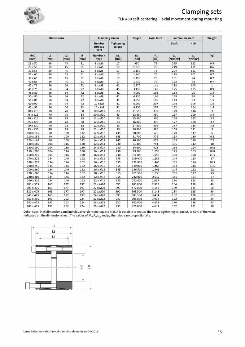
Clamping setsTLK 450 self-centering – axial movement during mounting
Dimensions Clamping screws Torque Axial force Surface pressure Weight
Number DIN 912
12.9
Tightening torque
Shaft Hub
dxD [mm]
L1[mm]
L2[mm]
B [mm]
Number x type
MS
[Nm]M
T
[Nm]F
A
[kN]p
W
[N/mm²]p
N
[N/mm²][kg]
25 x 50 39 45 51 8 x M6 17 950 76 245 122 0.528 x 55 39 45 51 8 x M6 17 1,070 76 219 111 0.630 x 55 39 45 51 8 x M6 17 1.150 76 204 111 0.635 x 60 39 45 51 8 x M6 17 1,340 76 175 102 0.738 x 65 39 45 51 8 x M6 17 1,450 76 161 94 0.740 x 65 39 45 51 8 x M6 17 1,530 76 153 94 0.742 x 75 56 64 72 8 x M8 41 2,970 141 188 105 145 x 75 56 64 72 8 x M8 41 3,150 141 175 105 0.948 x 80 56 64 72 8 x M8 41 4,000 166 164 98 1.450 x 80 56 64 72 8 x M8 41 4,150 166 158 98 1.355 x 85 56 64 72 8 x M8 41 4,550 166 143 93 1.560 x 90 56 64 72 10 x M8 41 6,200 207 164 109 1.665 x 95 56 64 72 10 x M8 41 6,750 207 152 104 1.8
70 x 110 70 78 88 10 x M10 83 11.550 330 179 114 375 x 115 70 78 88 10 x M10 83 12.350 330 167 109 3.380 x 120 70 78 88 12 x M10 83 15.800 396 188 125 3.585 x 125 70 78 88 12 x M10 83 16,800 396 177 120 3.790 x 130 70 78 88 12 x M10 83 17,800 396 167 115 3.895 x 135 70 78 88 12 x M10 83 18,800 396 158 111 5
100 x 145 90 100 112 12 x M12 145 28,800 576 170 117 6110 x 155 90 100 112 12 x M12 145 31,700 576 155 110 6.2120 x 165 90 100 112 14 x M12 145 40,300 673 165 120 7.2130 x 180 104 116 130 12 x M14 230 51,400 791 155 112 10140 x 190 104 116 130 14 x M14 230 64,600 923 168 124 10,2150 x 200 104 116 130 16 x M14 230 79,100 1,055 179 135 10.8160 x 210 104 116 130 16 x M14 230 84,400 1,055 168 128 11.5170 x 225 134 146 162 14 x M16 355 109,000 1,283 149 113 17180 x 235 134 146 162 16 x M16 355 132.000 1,466 161 124 18.5190 x 250 134 146 162 16 x M16 355 139,000 1,466 153 116 21.5200 x 260 134 146 162 16 x M16 355 146,500 1.466 145 112 22220 x 285 134 146 162 20 x M16 355 201,500 1,833 165 127 25240 x 305 134 146 162 22 x M16 355 242,000 2.017 166 131 27260 x 325 134 146 162 22 x M16 355 262,000 2,017 154 123 30280 x 355 165 177 197 20 x M20 690 400,000 2,862 164 130 46300 x 375 165 177 197 22 x M20 690 472,000 3,148 169 135 50320 x 405 165 177 197 22 x M20 690 503,500 3,148 158 125 60340 x 425 165 177 197 24 x M20 690 583,500 3,434 162 130 65360 x 455 190 202 224 22 x M22 930 705,000 3,918 152 120 89380 x 475 190 202 224 26 x M22 930 880,000 4,631 170 136 93400 x 495 190 202 224 26 x M22 930 926,000 4.631 162 131 98
Other sizes, inch dimensions and individual versions on request. N.B. It is possible to reduce the screw tightening torque MS to 60% of the value
indicated on the dimension sheet. The values of MT, F
A, p
W and p
N then decrease proportionally.

36 Lenze Selection · Mechanical clamping elements en 04/2016
Features• For very high torques• Absorption of bending torques (Please consult our technicians)• Standard dimensions• Self-centering• With axial movement during mounting
Mounting: Clean and lightly oil the contact surfaces of shaft and hub. Insert clamping set into seat of hub and push onto the shaft. Tighten the clamping screws in steps crosswise with a torque wrench until 50% of the indicated tightening torque M
S is reached. Then repeat the process
with the full tightening torque. Starting with the last tightened screw and proceeding in a clockwise direction, check that all the clamping screws have been tightened with the correct tightening torque M
S. This concludes the mounting process. If the clamping screws
are to be capable of being undone manually, they can be pretensioned with 60% of the indicated tightening torque. The values of M
T and F
A
indicated in the table have been calculated for mounting with oil.
N.B.: Do not use oil containing molybdenum disulphide or extreme-pressure additives and do not use grease. The coefficient of friction would otherwise be considerably reduced.
Dismantling: Unscrew clamping screws and insert into the dismantling threads of the front conical ring. Tighten screws in steps crosswise and uniformly with 50% of the tightening torque. Repeat the process with the full tightening torque. If the front conical ring becomes detached, tighten the screws further and repeat the process as described above in order to release the rear conical ring.
N.B.: If, after dismantling, the clamping set TLK 451/TLK 451.0 is to be mounted again, it must be ensured that the dismantling threads of the front conical ring and the connection flange are in their original position.
Tolerances, roughness depth: A machine turned finish is sufficient.Maximum permissible tolerances: h8 for the shaft H8 for the hub Maximum roughness depth: R
t max. 16 µm (R
a 3 µm – R
z 13 µm)
How the minimum hub diameter is calculated is shown on page 12. We will be happy to advise you with regard to individual dimensioning and any other questions you may have.
Clamping setsTLK 451/TLK 451.0 self-centering – axial movement during mounting

37Lenze Selection · Mechanical clamping elements en 04/2016
Clamping setsTLK 451/TLK 451.0 self-centering – axial movement during mounting
Other sizes, inch dimensions and individual versions on request.
Dimensions
Clamping screws
DIN 912 12.9
TLK 451 TLK 451.0
Tightening torque Torque Axial
force
Surface pressure on Tightening
torque Torque Axial force
Surface pressure on
Weight TLK 451
TLK 451.0Shaft Hub Shaft HubdxD
[mm]L1
[mm]L2
[mm]B
[mm] Number x
typeM
S[Nm]
MT
[Nm]F
A[kN]
pW
[N/mm2]p
N[N/mm2]
MS
[Nm]M
T
[Nm]F
A[kN]
pW
[N/mm2]p
N[N/mm2] [kg]
70 x 110 50 60 70 8 x M10 49 4.180 120 113 64 83 7,090 203 192 109 2.380 x 120 50 60 70 10 x M10 49 5,980 150 124 73 83 10,130 253 210 124 2.590 x 130 50 60 70 11xM10 49 7,400 165 121 75 83 12,540 279 205 126 2.7
100 x 145 60 70 82 10 x M12 86 10,930 219 121 74 145 18,440 369 204 125 4.1110 x 155 60 70 82 10 x M12 86 12,000 219 110 69 145 20,200 369 185 117 4.4120 x 165 60 70 82 11 x M12 86 14,400 241 111 72 145 24,300 406 187 121 4.8130 x 180 65 79 91 14 x M12 86 19,900 306 118 77 145 33,500 516 199 129 6.3140 x 190 65 79 91 15 x M12 86 22,900 328 117 78 145 38,700 553 198 131 6.6150 x 200 65 79 91 15 x M12 86 24,600 328 110 74 145 41,400 553 185 124 7.8160 x 210 65 79 91 16 x M12 86 28,000 350 110 75 145 47,200 590 185 126 7.4170 x 225 78 92 106 15 x M14 135 37,800 446 109 74 230 64,500 759 185 126 10,7180 x 235 78 92 106 15 x M14 135 40,100 446 103 71 230 68,300 759 175 121 11.3190 x 250 88 102 116 16 x M14 135 45,100 475 90 62 230 76,900 810 153 106 14.6200 x 260 88 102 116 18 x M14 135 53,400 535 96 67 230 91,100 911 163 115 15.3220 x 285 96 108 124 15 x M16 210 68,600 624 94 66 355 116,000 1,055 159 112 20.2240 x 305 96 108 124 20 x M16 210 99,800 832 115 82 355 168,800 1,407 194 139 21.8260 x 325 96 108 124 20 x M16 210 108,000 832 106 77 355 182,000 1,407 179 130 23.4280 x 355 96 110 130 15 x M20 410 137,000 979 122 85 690 230,000 1,647 205 143 30300 x 375 96 110 130 16 x M20 410 156,000 1,044 121 86 690 263,000 1,757 204 145 31.2320 x 405 124 136 156 20 x M20 410 208,000 1,305 104 75 690 351,000 2,196 175 126 48340 x 425 124 136 156 20 x M20 410 221,000 1,305 98 71 690 373,000 2,196 165 120 51360 x 455 140 155 177 20 x M22 550 291,000 1,617 101 73 930 492,000 2,734 171 124 69380 x 475 140 155 177 20 x M22 550 307,000 1.617 96 70 930 519,000 2,734 162 118 73400 x 495 140 155 177 22 x M22 550 355,000 1,778 100 74 930 601,000 3,007 169 125 76420 x 515 140 155 177 24 x M22 550 407,000 1,940 104 77 930 688,000 3,280 176 131 80440 x 535 140 155 177 24 x M22 550 426,000 1,940 99 75 930 721,000 3,280 168 126 81460 x 555 140 155 177 24 x M22 550 446,000 1,940 95 72 930 754,000 3,280 160 122 85480 x 575 140 155 177 25 x M22 550 485,000 2,021 95 72 930 820,000 3,417 160 122 88500 x 595 140 155 177 25 x M22 550 505,000 2,021 91 70 930 854,000 3.417 154 118 91520 x 615 140 155 177 28 x M22 550 588,000 2,263 98 76 930 995,000 3,827 165 128 95540 x 635 140 155 177 28 x M22 550 611,000 2,263 94 73 930 1,033,000 3,827 159 124 98560 x 655 140 155 177 30 x M22 550 679,000 2,425 97 76 930 1,148,000 4,101 165 129 101580 x 675 140 155 177 30 x M22 550 703,000 2.425 94 74 930 1,189,000 4,101 159 125 104600 x 695 140 155 177 30 x M22 550 727,000 2,425 91 72 930 1,230,000 4,101 154 121 108

38 Lenze Selection · Mechanical clamping elements en 04/2016
Features• For very high torques• Absorption of bending torques (Please consult our technicians)• Standard dimensions• Self-centering• With axial movement during mounting
Mounting: Clean and lightly oil the contact surfaces of shaft and hub. Insert clamping set into seat of hub and push onto the shaft. Tighten the clamping screws in steps crosswise with a torque wrench until 50% of the indicated tightening torque M
S is reached. Then repeat
the process with the full tightening torque. Starting with the last tightened screw and proceeding in a clockwise direction, check that all the clamping screws have been tightened with the correct tightening torque M
S. This concludes the mounting process. If
the clamping screws are to be capable of being undone manually, they can be pretensioned with 60% of the indicated tightening torque. The values of M
T and F
A
indicated in the table have been calculated for mounting with oil.
N.B.: Do not use oil containing molybdenum disulphide or extreme-pressure additives and do not use grease. The coefficient of friction would otherwise be considerably reduced.
Dismantling: Unscrew clamping screws and insert into the dismantling threads of the front conical ring. Tighten screws in steps crosswise and uniformly with 50% of the tightening torque. Repeat the process with the full tightening torque. If the front conical ring becomes detached, tighten the screws further and repeat the process as described above in order to release the rear conical ring.
N.B.: If, after dismantling, the clamping set TLK 452 is to be mounted again, it must be ensured that the dismantling windings of the front conical rings and the connection flange are in their original position.
Tolerances, roughness depth: A machine turned finish is sufficient.Maximum permissible tolerances: h8 for the shaft H8 for the hub Maximum roughness depth: R
t max. 16 µm (R
a 3 µm – R
z 13 µm)
How the minimum hub diameter is calculated is shown on page 12. We will be happy to advise you with regard to individual dimensioning and any other questions you may have.
Clamping setsTLK 452 self-centering – axial movement during mounting

39Lenze Selection · Mechanical clamping elements en 04/2016
Clamping setsTLK 452 self-centering – axial movement during mounting
Other sizes, inch dimensions and individual versions on request. N.B. It is possible to reduce the screw tightening torque MS to 60% of the value
indicated on the dimension sheet. The values of MT, F
A, p
W and p
N then decrease proportionally.
Dimensions Clamping screws Torque Axial force Surface pressure Weight
Number DIN 912
12.9
Tightening torque
Shaft Hub
dxD [mm]
L1[mm]
L2[mm]
B [mm]
Number x type
MS
[Nm]M
T
[Nm]F
A
[kN]p
W
[N/mm²]p
N
[N/mm²][kg]
25 x 55 32 40 46 6 x M6 17 860 69 307 105 0.528 x 55 32 40 46 6 x M6 17 970 69 274 105 0.430 x 55 32 40 46 6 x M6 17 1.040 69 256 105 0.435 x 60 44 54 60 7 x M6 17 1,410 81 180 81 0.638 x 75 44 54 62 7 x M8 41 2,840 150 307 120 1.140 x 75 44 54 62 7 x M8 41 2,990 150 292 120 1.142 x 75 44 54 62 7 x M8 41 3.140 150 278 120 145 x 75 44 54 62 7 x M8 41 3,360 150 259 120 148 x 80 56 64 72 8 x M8 41 4,100 171 205 101 1.450 x 80 56 64 72 8 x M8 41 4.270 171 197 101 1.355 x 85 56 64 72 9 x M8 41 5,280 192 202 107 1.460 x 90 56 64 72 10 x M8 41 6,410 214 205 112 1.565 x 95 56 64 72 10 x M8 41 6,940 214 190 107 1.6
70 x 110 70 78 88 10 x M10 83 11,800 339 222 117 3.175 x 115 70 78 88 10 x M10 83 12,700 339 207 112 3.380 x 120 70 78 88 11 x M10 83 14.900 373 213 118 3.485 x 125 70 78 88 12 x M10 83 17,300 407 219 123 3.690 x 130 70 78 88 12 x M10 83 18,300 407 207 119 3.895 x 135 70 78 88 12 x M10 83 19,300 407 196 114 3.9
100 x 145 90 100 112 11 x M12 145 27,100 544 206 110 6.1110 x 155 90 100 112 12 x M12 145 32,600 593 204 113 6.6120 x 165 90 100 112 14 x M12 145 41,500 692 218 124 7,1130 x 180 104 116 130 12 x M14 230 52,800 814 198 115 10140 x 190 104 116 130 14 x M14 230 66,400 949 214 127 11150 x 200 104 116 130 15 x M14 230 76,200 1.017 214 130 11160 x 210 104 116 130 16 x M14 230 86,700 1,085 214 132 12170 x 225 134 148 164 14 x M16 360 112,000 1,319 196 116 18180 x 235 134 148 164 15 x M16 360 127,000 1,413 198 119 19190 x 250 134 148 164 16 x M16 360 143,000 1,508 200 119 22200 x 260 134 148 164 16 x M16 360 150,000 1,508 190 115 23220 x 285 134 148 164 18 x M16 360 186,000 1,696 195 118 27240 x 305 134 150 166 20 x M16 360 226,000 1,885 198 122 29260 x 325 134 150 166 21 x M16 360 257,000 1.979 192 121 31280 x 355 165 177 197 18 x M20 690 370,000 2,648 197 120 48300 x 375 165 177 197 20 x M20 690 441,000 2,942 205 126 51320 x 405 165 177 197 21 x M20 690 494,000 3,089 202 123 62340 x 425 165 177 197 22 x M20 690 550,000 3,236 199 122 66360 x 455 190 202 224 21 x M22 930 692,000 3,845 193 118 90380 x 475 190 202 224 22 x M22 930 765,000 4,028 191 118 95400 x 495 190 202 224 24 x M22 930 878,000 4,394 198 124 99

40 Lenze Selection · Mechanical clamping elements en 04/2016
Features• For medium to high torques• Small number of screws• Quick mounting• Self-centering• No axial movement during mounting
Mounting: Clean and lightly oil the contact surfaces of the shafts. Place rigid coupling onto the connecting shafts. Gradually tighten clamping screws in steps crosswise to the indicated tightening torque M
S. The values of M
T and F
A in the table have been calculated for
mounting with oil. N.B.: Do not use oil containing molybdenum disulphide or extreme-pressure additives and do not use grease. The coefficient of friction would otherwise be considerably reduced.
Dismantling:Undo and remove all clamping screws. As a rule, the coupling becomes detached automatically. Otherwise, hit lightly with a hammer on the loosened screw heads in order to push the rear conical ring back.
Tolerances, roughness depth: A machine turned finish is sufficient.Maximum permissible tolerances: h8 for the shaft Maximum roughness depth: R
t max. 16 µm (R
a 3 µm – R
z 13 µm)
We will be happy to advise you with regard to individual dimensioning and any other questions you may have.
Rigid shaft couplingsTLK 500 self-centering – no axial movement during mounting
Dimensions Torque Axial force Clamping screws Weight
Number DIN 912 12.9
Tightening torque
dxD [mm]
L[mm]
B [mm]
MT
[Nm]F
A
[kN]Number x type M
S
[Nm][kg]
17 x 50 50 56 200 24 4 x M6 17 0.518 x 50 50 56 220 24 4 x M6 17 0.519 x 50 50 56 230 24 4 x M6 17 0.520 x 50 50 56 240 24 4 x M6 17 0.522 x 55 60 66 260 24 4 x M6 17 0.624 x 55 60 66 290 24 4 x M6 17 0.625 x 55 60 66 450 36 6 x M6 17 0.628 x 60 60 66 510 36 6 x M6 17 0.730 x 60 60 66 550 36 6 x M6 17 0.732 x 75 60 68 720 45 4 x M8 41 1.335 x 75 75 83 790 45 4 x M8 41 1.338 x 75 75 83 850 45 4 x M8 41 1.340 x 75 75 83 900 45 4 x M8 41 1.342 x 90 75 83 1,400 67 6 x M8 41 2.845 x 90 85 93 1.520 67 6 x M8 41 2.548 x 90 85 93 1.620 67 6 x M8 41 2.450 x 90 85 93 1,690 67 6 x M8 41 2.3
55 x 105 85 93 2,470 90 8 x M8 41 3.360 x 10⁵ 85 93 2,710 90 8 x M8 41 3.265 x 10⁵ 85 93 2.930 90 8 x M8 41 370 x 125 100 110 3,770 107 6 x M10 83 5.475 x 125 100 110 4,030 107 6 x M10 83 580 x 125 100 110 4,300 107 6 x M10 83 4.7
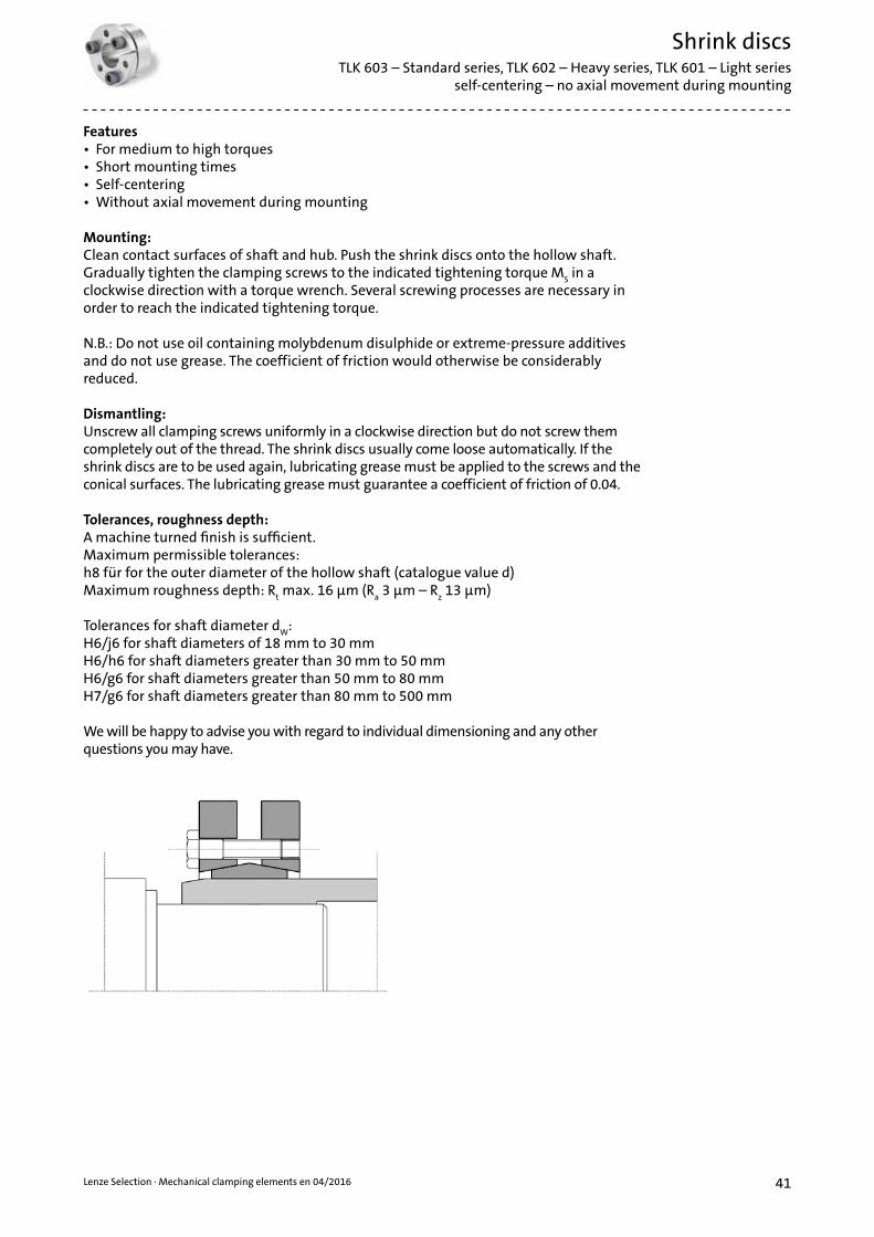
41Lenze Selection · Mechanical clamping elements en 04/2016
Shrink discs TLK 603 – Standard series, TLK 602 – Heavy series, TLK 601 – Light series
self-centering – no axial movement during mounting
Features• For medium to high torques• Short mounting times• Self-centering• Without axial movement during mounting
Mounting: Clean contact surfaces of shaft and hub. Push the shrink discs onto the hollow shaft. Gradually tighten the clamping screws to the indicated tightening torque M
S in a
clockwise direction with a torque wrench. Several screwing processes are necessary in order to reach the indicated tightening torque.
N.B.: Do not use oil containing molybdenum disulphide or extreme-pressure additives and do not use grease. The coefficient of friction would otherwise be considerably reduced.
Dismantling: Unscrew all clamping screws uniformly in a clockwise direction but do not screw them completely out of the thread. The shrink discs usually come loose automatically. If the shrink discs are to be used again, lubricating grease must be applied to the screws and the conical surfaces. The lubricating grease must guarantee a coefficient of friction of 0.04.
Tolerances, roughness depth: A machine turned finish is sufficient.Maximum permissible tolerances: h8 für for the outer diameter of the hollow shaft (catalogue value d) Maximum roughness depth: R
t max. 16 µm (R
a 3 µm – R
z 13 µm)
Tolerances for shaft diameter dW
: H6/j6 for shaft diameters of 18 mm to 30 mm H6/h6 for shaft diameters greater than 30 mm to 50 mm H6/g6 for shaft diameters greater than 50 mm to 80 mm H7/g6 for shaft diameters greater than 80 mm to 500 mm
We will be happy to advise you with regard to individual dimensioning and any other questions you may have.

42 Lenze Selection · Mechanical clamping elements en 04/2016
Shrink discs TLK 603 self-centering – no axial movement during mounting – Standard series
Type Shaft diameter
Torque Axial force Dimensions Clamping screws Weight
Type DIN 931 10.9
Tightening torque
d1[mm]
dw
[mm]M
T
[Nm]F
A
[kN]D
[mm]I
[mm]L
[mm]d1
[mm]e
[mm]Number x
typeM
S
[Nm][kg]
14 11 30 6 38 7 11 23 2 4 x M5* 4 0.112 50 9
16 13 70 10 41 11 15 26 2 5 x M5* 4 0.114 90 13
2419 170 25
50 14 19.5 36 2.75 6 x M5* 4 0.220 210 2721 250 29
3024 300 29
60 16 21.5 44 2.75 7 x M5* 4 0.325 340 3126 380 33
3628 440 50
72 18 23.5 52 2.75 5 x M6 12 0.430 570 5831 630 58
4432 620 64
80 20 25.5 61 2.75 7 x M6 12 0.635 780 7436 860 77
5038 940 79
90 22 27.5 70 2.75 8 x M6 12 0.840 1.160 8642 1,380 92
5542 1,160 79
100 23 30.5 75 3.75 8 x M6 12 1.145 1,520 8848 1,880 97
6248 1,850 100
110 23 30.5 86 3.75 10 x M6 12 1.350 2,200 11152 2,400 117
6850 2,000 97
115 23 30.5 86 3.75 10 x M6 12 1.455 2,500 10660 3,150 120
7555 2,500 119
138 25 32.5 100 3.75 7 x M8 30 1.760 3,200 13765 3,950 155
8060 3,200 124
145 25 32.5 100 3.75 7 x M8 30 1.965 3,900 14070 4,600 158
8565 4,800 175
155 30 39 114 4.5 10 x M8 30 3.570 6,100 19575 7,400 216
9065 4,750 170
155 30 39 114 4.5 10 x M8 30 3.370 6,000 19075 7,250 210
10070 6,900 195
170 34 44 124 5 12 x M8 30 4,775 7,500 22080 9,000 240
11075 7,200 229
185 39 50 136 5.5 9 x M10 59 5.980 9,000 25285 10,800 262
11580 7,400 235
188 39 50 141 5.5 9 x M10 59 5.585 9,200 25990 11,100 269
12080 10,600 285
215 42 54 160 6 12 x M10 59 985 13,300 31490 14,500 340
12585 11,000 296
215 42 54 160 6 12 x M10 59 8.390 13,000 32495 15,000 352
13090 11,300 304
215 42 54 160 6 12 x M10 59 895 13,300 333100 15,400 362
14095 15,100 367
230 46 60.5 175 7.25 10 x M12 100 10100 17,600 396105 20,100 425
155105 22,000 447
265 50 64.5 192 7.25 12 x M12 100 15110 25,000 478115 28,000 509
160110 22,600 460
265 50 64.5 192 7.25 12 x M12 100 14.5115 25,700 490120 28,800 520
165115 31,000 595
290 56 71 210 7.5 8 x M16 250 22120 35,000 630125 39,000 655
* Screw quality 8.8

43Lenze Selection · Mechanical clamping elements en 04/2016
Shrink discs TLK 603 self-centering – no axial movement during mounting – Standard series
Type Shaft diameter
Torque Axial force Dimensions Clamping screws Weight
Type DIN 931 10.9
Tightening torque
d1[mm]
dw
[mm]M
T
[Nm]F
A
[kN]D
[mm]I
[mm]L
[mm]d1
[mm]e
[mm]Number x
typeM
S
[Nm][kg]
170120 31,900 610
290 56 71 210 7.5 8 x M16 250 21125 36,000 640130 40,100 670
175125 36,000 605
300 56 71 220 7.5 8 x M16 250 22130 41,000 639135 45,000 675
180130 37,000 800
300 56 71 220 7.5 8 x M16 250 21135 42,200 840140 46,300 885
185135 52,000 778
330 71 86 236 7.5 10 x M16 250 37140 57,000 819145 62,000 861
190140 53,500 800
330 71 86 236 7.5 10 x M16 250 36145 58,700 840150 63,800 885
195140 65,000 933
350 71 86 246 7.5 12 x M16 250 41150 76,000 1.025155 81,500 1.071
200150 74,000 990
350 71 86 246 7.5 12 x M16 250 41155 80,000 1.035160 86,000 1,080
220160 95,000 1,190
370 88 104 270 8 15 x M16 250 54165 102,000 1,239170 110,000 1,290
240170 120,000 1.464
405 92 109 295 8.5 12 x M20 490 67180 138,000 1.576190 156,000 1.675
260190 164,000 1,760
430 103 120 321 8.5 14 x M20 490 82200 184,000 1,880210 205,000 2,010
280210 217,000 2,090
460 114 134 346 10 16 x M20 490 102220 244,000 2,220230 270,000 2,350
300230 275,000 2,431
485 122 142 364 10 18 x M20 490 118240 295,000 2,567245 315,000 2,636
320240 312,000 2,647
520 122 142 386 10 20 x M20 490 131250 340,000 2,786260 374,000 2,900
340250 390,000 3,119
570 134 156 408 11 24 x M20 490 186260 422,500 3,249270 460,000 3,400
350270 442,000 3,276
580 140 162 432 11 24 x M20 490 195280 480,000 3,430285 500,000 3,500
360280 463,000 3,310
590 140 162 432 11 24 x M20 490 204290 502,000 3,461295 522,000 3,536
380290 567,000 3,910
645 144 168 458 12 20 x M24 840 239300 610,000 4,080310 658,000 4,248
390300 624,000 4,160
660 144 168 468 12 21 x M24 840 260310 671,000 4,330320 718,000 4,484
400315 670,000 4,260
680 144 168 480 12 21 x M24 840 280320 695,000 4,345330 744,000 4,500
420330 780,000 4,850
690 164 188 504 12 24 x M24 840 316340 840,000 5,040350 900,000 5,220
440340 806,000 4,740
750 177 202 527 12.5 24 x M24 840 408350 860,000 4,910360 917,000 5,090
460360 1,000,000 5,670
770 177 202 547 12.5 28 x M24 840 420370 1,070,000 5,860380 1,140,000 6,050
480380 1,170,000 6,150
800 188 213 570 12.5 30 x M24 840 505390 1,240,000 6,350400 1,310,000 6,550
Other sizes, inch dimensions and individual versions on request.

44 Lenze Selection · Mechanical clamping elements en 04/2016
Shrink discs TLK 602 self-centering – no axial movement during mounting – Heavy series
Type Shaft diameter
Torque Axial force Dimensions Clamping screws Weight
Type DIN 931 10.9
Tightening torque
d1[mm]
dw
[mm]M
T
[Nm]F
A
[kN]D
[mm]I
[mm]L
[mm]d1
[mm]e
[mm]Number x
typeM
S
[Nm][kg]
12585 15,000 355
215 55 65 160 5 10 x M12 100 1190 17,500 38895 20,000 422
14095 20,600 433
230 60 74 175 7 12 x M12 100 13100 23,500 469105 26,500 500
155105 28,600 550
265 66 80 198 7 15 x M12 100 20110 32,500 590115 36,400 630
165115 41,000 740
290 72 88 210 8 10 x M16 250 26120 46,000 785125 50,700 815
175125 47,000 750
300 72 88 220 8 10 x M16 250 29130 52,000 795135 57,000 840
185135 72,000 1,100
330 92 112 236 10 14 x M16 250 47140 78,000 1,150145 86,000 1,200
195140 75,000 1,075
350 92 112 246 10 14 x M16 250 53150 88,000 1,180155 96,000 1,235
200145 85,000 1,170
350 92 112 246 10 15 x M16 250 50150 92,500 1,230155 100,000 1,290
220160 127,000 1,590
370 114 134 270 10 20 x M16 250 65165 136,000 1,650170 146,500 1,720
240170 155,000 1,820
405 120 144 295 12 15 x M20 490 87180 176,000 1,960190 198,000 2,080
260190 213,000 2,260
430 136 160 321 12 18 x M20 490 100200 240,000 2,420210 268,000 2,580
280210 285,000 2,740
460 148 172 346 12 21 x M20 490 132220 320,000 2,910230 355,000 3,090
300230 341,000 2,960
485 152 176 364 12 22 x M20 490 140240 376,000 3,130245 394,000 3,215
320240 378,000 3,150
520 160 184 386 12 24 x M20 490 165250 415,000 3,325260 451,000 3,470
340250 489,500 3,910
570 176 200 420 12 21 x M24 840 240260 530,000 4,075270 578,000 4,275
350270 556,000 4,122
580 176 200 425 12 21 x M24 840 247280 604,000 4,320285 629,000 4,415
360280 612,000 4,370
590 180 204 432 12 22 x M24 840 250290 663,000 4,570295 689,000 4,670
380290 618,000 4,270
645 180 204 458 12 22 x M24 840 320300 668,000 4,455310 719,000 4,645
390300 708,000 4,715
660 188 212 468 12 24 x M24 840 350310 762,000 4,910320 814,500 5,090
400315 765,000 4,855
680 188 212 480 12 24 x M24 840 370320 788,000 4,927330 845,000 5,125
420330 999,000 6,055
690 214 238 504 12 30 x M24 840 410340 1,068,000 6,285350 1,140,000 6,515
440340 1,058,000 6,230
750 224 252 527 14 24 x M27 1250 525350 1,130,000 6,460360 1,204,000 6,690
460360 1,320,000 7,440
770 224 252 547 14 28 x M27 1250 540370 1,420,000 7,700380 1,500,000 7,950
Other sizes, inch dimensions and individual versions on request.

45Lenze Selection · Mechanical clamping elements en 04/2016
Shrink discs TLK 601 self-centering – no axial movement during mounting – Light series
Type Shaft diameter
Torque Axial force Dimensions Clamping screws Weight
Type DIN 931 10.9
Tightening torque
d1[mm]
dw
[mm]M
T
[Nm]F
A
[kN]D
[mm]I
[mm]L
[mm]d1
[mm]e
[mm]Number x
typeM
S
[Nm][kg]
12595 10,550 220
185 39 51 158 6 8 x M10 59 6100 12,100 240105 13,800 260
140110 14,800 265
220 39 51 175 6 9 x M10 59 8120 18,640 310125 20,500 325
155130 24,000 365
245 39 51 192 6 11 x M10 59 10135 26,400 390140 29,000 410
165135 32,000 475
260 46 62 210 8 10 x M12 100 14140 35,200 500145 38,500 530
175145 39,000 535
275 46 62 220 8 11 x M12 100 16150 42,400 560155 46,000 590
185155 46,600 600
295 46 62 225 8 12 x M12 100 20160 50,300 625165 54,000 650
195165 63,000 760
315 56 72 237 8 15 x M12 100 27170 67,700 795175 72,500 825
200175 74,000 850
330 56 72 242 8 16 x M12 100 30180 79,500 890185 84,500 915
220180 82,800 920
345 66 84 265 9 10 x M16 250 35190 93,500 980200 105,000 1,055
240200 113,000 1,135
370 66 84 290 9 12 x M16 250 44210 127,500 1,210215 134,500 1,250
260220 149,000 1,350
395 72 92 310 10 14 x M16 250 48230 165,000 1,435235 173,000 1,475
280230 171,000 1,485
425 84 104 333 10 16 x M16 250 60240 189,000 1,570250 208,000 1,660
300250 215,000 1,720
460 84 104 358 10 18 x M16 250 75260 234,000 1,800270 255,000 1,890
320270 260,000 1,940
495 84 106 378 11 20 x M16 250 84280 284,000 2,030290 306,000 2.125
340290 300,000 2,070
535 84 106 402 11 21 x M16 250 100300 324,400 2,160305 337,000 2,210
350300 372,000 2,485
545 100 122 413 11 16 x M20 490 120305 385,000 2,540310 400,000 2,590
360300 360,000 2,400
555 100 122 423 11 16 x M20 490 125310 388,000 2,500320 415,000 2,590
380320 435,000 2,720
585 112 136 442 12 18 x M20 490 150325 451,000 2,780330 467,000 2,835
390330 505,000 3,060
595 112 136 452 12 20 x M20 490 156340 540,000 3,175350 577,000 3,295
400340 550,000 3,235
615 112 136 462 12 21 x M20 490 170350 587,000 3,360360 626,000 3,480
420350 578,000 3,300
630 120 144 485 12 22 x M20 490 185360 617,000 3,425370 655,000 3,545
440370 677,000 3,660
660 120 144 505 12 24 x M20 490 205380 719,000 3,785390 762,000 3,910
460390 840,000 4,320
685 132 158 527 13 28 x M20 490 235400 890,000 4,460410 935,000 4,580
Other sizes, inch dimensions and individual versions on request.

46 Lenze Selection · Mechanical clamping elements en 04/2016
Shrink discsCustomised shrink disc solutions
Split version* Half I version*
Half S version* Use of TLK 603 as coupling between shafts with different diameters
Special version with brake holder Simultaneous attachment of a sprocket and a hollow shaft
*When ordering, indicate dimension X

47Lenze Selection · Mechanical clamping elements en 04/2016
Shrink discs TLK 622, TLK 623, TLK 681, TLK 683 self-centering –
no axial movement during mounting
Features• For very high torques• Short mounting times• Self-centering• Without axial movement during mounting
Mounting: Clean contact surfaces of shaft and hub. Push the shrink discs onto the hollow shaft. Gradually tighten the clamping screws to the indicated tightening torque M
S in a
clockwise direction with a torque wrench. Several screwing processes are necessary in order to reach the indicated tightening torque.
N.B.: Do not use oil containing molybdenum disulphide or extreme-pressure additives and do not use grease. The coefficient of friction would otherwise be considerably reduced.
Dismantling:Unscrew all clamping screws uniformly in a clockwise direction but do not screw them completely out of the thread. The shrink discs usually come loose automatically. If the shrink discs are to be used again, lubricating grease must be applied to the screws and the conical surfaces. The lubricating grease must guarantee a coefficient of friction of 0.04.
Tolerances, roughness depth: A machine turned finish is sufficient.Maximum permissible tolerances: f7 for the outer diameter of the hollow shaft (catalogue value d) Maximum roughness depth: R
t max. 16 µm (R
a 3 µm – R
z 13 µm)
Tolerances for shaft diameter dW
: H7/h6 for shaft diameters up to 150 mm H7/g6 for shaft diameters from 155 mm
Series TLK 622 and TLK 623 clamping screws DIN 931 10.9 Series TLK 681 and TLK 683 clamping screws DIN 931 12.9
We will be happy to advise you with regard to individual dimensioning and any other questions you may have.

48 Lenze Selection · Mechanical clamping elements en 04/2016
Shrink discs TLK 622 self-centering – no axial movement during mounting TLK 681 self-centering – no axial movement during mounting
Other sizes, inch dimensions and individual versions on request.
TypeShaft
diameter
TLK 622 TLK 681
DimensionsClamping
screws DIN 931
WeightTorque Axial force
Tightening torque
Torque Axial force
Tightening torque
d[mm]
dw
[mm]M
T
[Nm]F
A
[kN]M
S
[Nm]M
T
[Nm]F
A
[kN]M
S
[Nm]D
[mm]I
[mm]L
[mm]d1
[mm]e
[mm]Type [kg]
12 9 20 5 12 38 10 11 24 1 M6 0.110 40 8
14 11 30 6 12 38 10 11 26 1 M6 0.112 50 9
16 13 70 10 12 41 13.5 15 28 1.5 M6 0.114 90 13
18 15 80 11 12 44 13.5 15 30 1.5 M6 0.116 110 14
20 17 150 18 12 47 13.5 15 32 1.5 M6 0.118 180 20
2419 160 17
12 50 16 18 36 2 M6 0.220 210 2022 280 25
3024 270 23
12 60 18 20 44 2 M6 0.325 320 2526 360 28
3627 440 32
30 72 20 22 52 2 M8 0.530 610 4133 820 50
4434 690 41
30 80 22 24 61 2 M8 0.635 770 4437 920 50
5038 1.110 58
301,500 78
35 90 23.5 26 68 2.5 M8 0.840 1.290 65 1,700 8542 1,510 71 1,900 93
5542 1,230 59
301,600 78
35 100 26 29 72 3 M8 1.145 1,530 68 2,000 8848 1,860 78 2,400 99
6248 1,670 70
302,200 91
35 110 26 29 80 3 M8 1.350 1,890 76 2,400 9852 2,120 81 2,700 104
6850 1,870 75
302,400 94
35 115 26 29 86 3 M8 1.355 2,450 89 3,000 11160 3,120 104 3,800 127
7555 2,330 85
593,700 136
70 138 27 31 100 4 M10 2.360 3,020 101 4,700 15765 3,810 117 5,800 178
8060 3,190 106
594,200 142
70 141 27 31 104 4 M10 2.365 4,060 123 5,200 16170 4,910 140 6,300 181
9065 5,400 166
595,900 181
70 155 34 38 114 4 M10 3.270 6,500 187 7,100 20375 7,800 208 8,500 226
10070 6,000 171
597,400 213
70 170 39 43 124 4 M10 4.375 7,200 192 8,900 23780 8,500 213 10,400 261
11080 10,000 249
10012,600 314
121 185 43.5 49 138 5.5 M12 5.885 11,700 275 14,600 34490 13,600 302 16,900 375
12085 11,900 280
10013,600 320
121 197 46.5 53 147 6.5 M12 6.990 13,800 307 15,700 34995 15,900 334 18,000 378
12590 14,400 319
10016,400 365
121 215 46.5 53 152 6.5 M12 8.795 16,500 347 18,800 395100 18,700 375 21,300 426
13595 18,100 382
16020,300 427
195 230 49.5 58 165 8.5 M14 11100 20,600 412 23,000 459110 26,000 473 28,900 525
140100 19,600 392
16023,000 459
195 230 49.5 58 170 8.5 M14 10105 22,100 421 25,800 492115 27,600 481 32,100 558
155110 26,500 482
16031,100 565
195 263 53.5 62 184 8.5 M14 15115 29,500 514 34,500 601125 36,100 578 42,000 672
165120 37,300 622
25044,000 734
300 290 58 68 198 10 M16 22125 41,200 659 48,500 776135 49,600 734 58,100 860
175130 45,000 692
25054,000 834
300 300 58 68 208 10 M16 23135 49,000 730 59,000 876145 58,000 805 70,000 962

49Lenze Selection · Mechanical clamping elements en 04/2016
Shrink discs TLK 622 self-centering – no axial movement during mounting TLK 681 self-centering – no axial movement during mounting
Type
Shaft diameter
TLK 622 TLK 681
DimensionsClamping
screws DIN 931
WeightTorque Axial force
Tightening torque
Torque Axial force
Tightening torque
d[mm]
dw
[mm]M
T
[Nm]F
A
[kN]M
S
[Nm]M
T
[Nm]F
A
[kN]M
S
[Nm]D
[mm]I
[mm]L
[mm]d1
[mm]e
[mm]Type [kg]
185140 64,000 916
25081,000 1,157
300 320 75 85 222 10 M16 33145 70,000 961 88,000 1,210155 82,000 1,053 102,000 1,319
200150 81,000 1,073
25096,000 1,279
300 340 75 85 238 10 M16 36155 87,000 1,120 103,000 1,333165 100,000 1,216 119,000 1,442
220160 103,000 1,283
490129,000 1,615
570 370 91 103 268 12 M20 53170 119,000 1,395 149,000 1,749180 136,000 1,509 169,000 1,883
240170 122,000 1,439
490151,000 1,773
570 405 94 107 288 13 M20 66180 140,000 1,555 172,000 1,909200 179,000 1,790 218,000 2,183
260190 163,000 1,715
490212,000 2,231
570 430 105 119 312 14 M20 82200 184,000 1,842 238,000 2,385220 231,000 2,099 297,000 2,696
280210 215,000 2,051
490279,000 2,661
570 460 116 132 334 16 M20 103220 240,000 2,186 311,000 2,825240 295,000 2,458 379,000 3,156
300220 270,000 2,456
840332,000 3,018
980 485 124 140 360 16 M24 120230 300,000 2,605 367,000 3,193250 363,000 2,906 443,000 3,545
320240 301,000 2,511
840404,000 3,370
980 520 124 140 380 16 M24 138250 332,000 2,655 444,000 3,549270 398,000 2,945 528,000 3,911
340250 390,000 3,118
840488,000 3,905
980 570 137 155 402 18 M24 189260 427,000 3,283 533,000 4,101280 506,000 3,617 630,000 4,498
350270 493,000 3,649
840616,000 4,563
980 580 142 162 414 20 M24 202280 535,000 3,825 669,000 4,778290 580,000 4.001 725,000 5,000
360270 496,000 3,676
840625,000 4,628
980 590 142 162 424 20 M24 207280 539,000 3,852 677,000 4,839300 631,000 4,206 790,000 5,264
380290 585,000 4,034
1,250725,000 5,000
1,450 640 146 166 454 20 M27 244300 632,000 4,215 783,000 5,220310 681,000 4,397 844,000 5,445
390290 640,000 4,411
1,250781,000 5.384
1,450 650 146 166 454 20 M27 249300 691,000 4,605 842,000 5,611320 799,000 4,996 971,000 6,069
420320 742,000 4,640
1,250969,000 6,057
1,450 670 166 186 486 20 M27 285330 797,000 4,829 1,038,000 6,290350 912,000 5,209 1,183,000 6,758
440340 945,000 5,557
1,2501,212,000 7,128
1,450 720 174 194 506 20 M27 357350 1,009,000 5,764 1,292,000 7,382370 1,143,000 6,181 1,460,000 7,891
460360 1,104,000 6,133
1,2501,393,000 7,739
1,450 770 174 194 534 20 M27 419370 1,174,000 6,345 1,479,000 7,995390 1,320,000 6,771 1,660,000 8,511
480380 1,300,000 6,843
1,6401,657,000 8,721
1,970 800 191 213 552 22 M30 492390 1,378,000 7,066 1,754,000 8,993410 1,541,000 7,516 1,956,000 9,542
500400 1,496,000 7,478
1,6401,887,000 9,435
1,970 850 191 213 572 22 M30 567410 1,581,000 7,711 1,992,000 9,717430 1,759,000 8,180 2,211,000 10,283
530430 1,930,000 8,976
1,6402,397,000 11,150
1,970 910 216 238 606 22 M30 744440 2,031,000 9,234 2,521,000 11,459460 2,243,000 9,752 2,778,000 12,078
560450 2,097,000 9,318
1,6402,545,000 11,313
1,970 940 216 238 632 22 M30 776460 2,201,000 9,572 2,671,000 11,611480 2,420,000 10,081 2,930,000 12,210
590470 2,593,000 11,032
1,6402,969,000 12,636
1,970 960 235 260 664 25 M30 835480 2,715,000 11,314 3,108,000 12,952500 2,970,000 11,881 3,397,000 13,587
620500 2,904,000 11,616
1,6403,402,000 13.608
1,970 1,020 261 286 706 25 M30 1,064520 3,169,000 12,190 3,708,000 14,261540 3,447,000 12,767 4,028,000 14,918
Other sizes, inch dimensions and individual versions on request.

50 Lenze Selection · Mechanical clamping elements en 04/2016
Shrink discs TLK 623 self-centering – no axial movement during mounting TLK 683 self-centering – no axial movement during mounting
TypeShaft
diameter
TLK 623 TLK 683
DimensionsClamping
screws DIN 931
WeightTorque Axial force
Tightening torque
Torque Axial force
Tightening torque
d[mm]
dw
[mm]M
T
[Nm]F
A
[kN]M
S
[Nm]M
T
[Nm]F
A
[kN]M
S
[Nm]D
[mm]I
[mm]L
[mm]d1
[mm]e
[mm]Type [kg]
140100 26,000 523
25030,000 607
300 230 64 74 174 10 M16 13105 30,000 562 34,000 650115 37,000 641 42,000 737
155110 36,000 646
25045,000 810
300 263 70 80 194 10 M16 19115 40,000 687 49,000 860125 48,000 772 60,000 959
165120 50,000 828
25063,000 1,047
300 290 77 88 204 11 M16 26125 55,000 877 69,000 1,105135 66,000 977 83,000 1.223
175130 61,000 943
25073,000 1,121
300 300 77 88 214 11 M16 27135 67,000 993 80.000 1,178145 79,000 1,094 94,000 1,292
185140 89,000 1,269
490106,000 1,512
570 320 100 112 232 12 M20 40145 96,000 1,330 115,000 1,582155 113,000 1,455 134,000 1,723
200150 104,000 1,391
490126,000 1,685
570 340 100 112 246 12 M20 44155 113,000 1,453 136,000 1,757165 130,000 1,577 157,000 1,900
220160 127,000 1,591
490162,000 2,027
570 370 121 134 266 13 M20 64165 137,000 1,661 174,000 2,112180 169,000 1,876 213,000 2,366
240170 157,000 1,847
490206,000 2,424
570 405 130 144 286 14 M20 81180 180,000 1,996 235,000 2,607200 230,000 2,300 298,000 2,978
260190 230,000 2,424
490285,000 3,000
570 430 144 160 306 16 M20 102200 260,000 2,600 321,000 3,207220 325,000 2,957 399,000 3,623
280210 306,000 2,918
840361,000 3,435
980 460 156 172 334 16 M24 126220 342,000 3,105 401,000 3,646240 418,000 3,485 489,000 4,074
300230 360,000 3,132
840461,000 4,010
980 485 158 176 354 18 M24 141240 398,000 3,314 508,000 4,230250 437,000 3,498 556,000 4,452
320240 430,000 3,580
840512,000 4,269
980 520 166 184 374 18 M24 171250 473,000 3,781 562,000 4,498270 565,000 4,186 670,000 4,960
340250 551,000 4,407
1,250661,000 5,288
1,450 570 186 206 404 20 M27 235260 603,000 4,637 722,000 5,552280 714,000 5,100 852,000 6,086
360270 671,000 4,969
1.250763,000 5,654
1,450 590 188 210 424 22 M27 251280 729,000 5,204 828,000 5,914300 852,000 5,679 966,000 6,438
390290 850,000 5,860
1,250978,000 6,743
1,450 650 196 220 456 24 M27 324300 917,000 6,116 1,054,000 7,029320 1,061,000 6,633 1,217,000 7,606
420320 1,007,000 6,294
1,2501,297,000 8,106
1,450 690 221 246 486 25 M27 409330 1,080,000 6,547 1,389,000 8,416350 1,235,000 7,058 1,582,000 9,040
440340 1,218,000 7,166
1,6401,583,000 9,312
1,970 750 233 258 514 25 M30 526350 1,301,000 7,433 1,687,000 9,642370 1,475,000 7,972 1,907,000 10,306
460360 1,402,000 7,791
1,6401,734,000 9,632
1,970 770 233 258 534 25 M30 544370 1,491,000 8,062 1,841,000 9,953390 1,678,000 8,606 2,067,000 10,599
480380 1,707,000 8,984
1,6402,076,000 10,926
1,970 800 270 298 552 28 M30 642390 1,809,000 9,277 2,198,000 11,270410 2,023,000 9,867 2,452,000 11,961
500400 1,993,000 9,963
1,6402,529,000 12,645
1,970 850 270 300 572 30 M30 741410 2,106,000 10,273 2,669,000 13,021430 2,342,000 10,895 2,962,000 13,777
530430 2,549,000 11,857
2,2103,093,000 14,385
2,650 890 306 338 616 32 M33 899440 2,683,000 12,196 3,252,000 14,782460 2,962,000 12,878 3,584,000 15,581
560450 2,837,000 12,609
2,2103,439,000 15,284
2,650 940 306 338 646 32 M33 1.000460 2,978,000 12,950 3,607,000 15,683480 3,272,000 13,634 3,956,000 16,485
Other sizes, inch dimensions and individual versions on request.

51Lenze Selection · Mechanical clamping elements en 04/2016
We will be happy to advise you with regard to your individual use case.
We work with you to find the best solution for your particular machine.

© 04/2016 | Mechanical Clamping Elements | 13510278 | 1.0 | ENSubject to technical alterations
www.lenze-selection.com