mechanical and mechatronics engineering department ... · recent advances and future challenges in...
TRANSCRIPT

Recent Advances and Future Challenges in the Modeling and Simulations of the injection of
Urea-Water-Solution for Automotive SCR Systems
Ehab Abu-Ramadan and Xianguo Li
Mechanical and Mechatronics Engineering Department
University of Waterloo
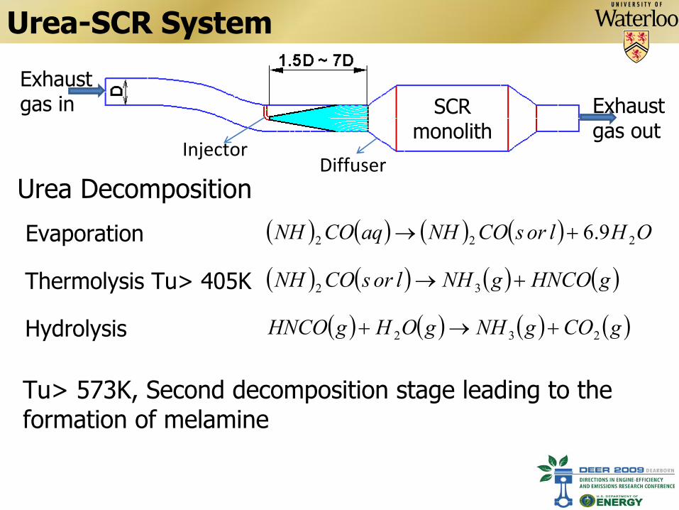
Urea-SCR System
Exhaust gas in Exhaust
gas outSCR
monolithInjector
DiffuserUrea Decomposition
OHlorsCONHaqCONH 222 9.6
gHNCOgNHlorsCONH 32
gCOgNHgOHgHNCO 232 Hydrolysis
Evaporation
Thermolysis Tu> 405K
Tu> 573K, Second decomposition stage leading to the formation of melamine
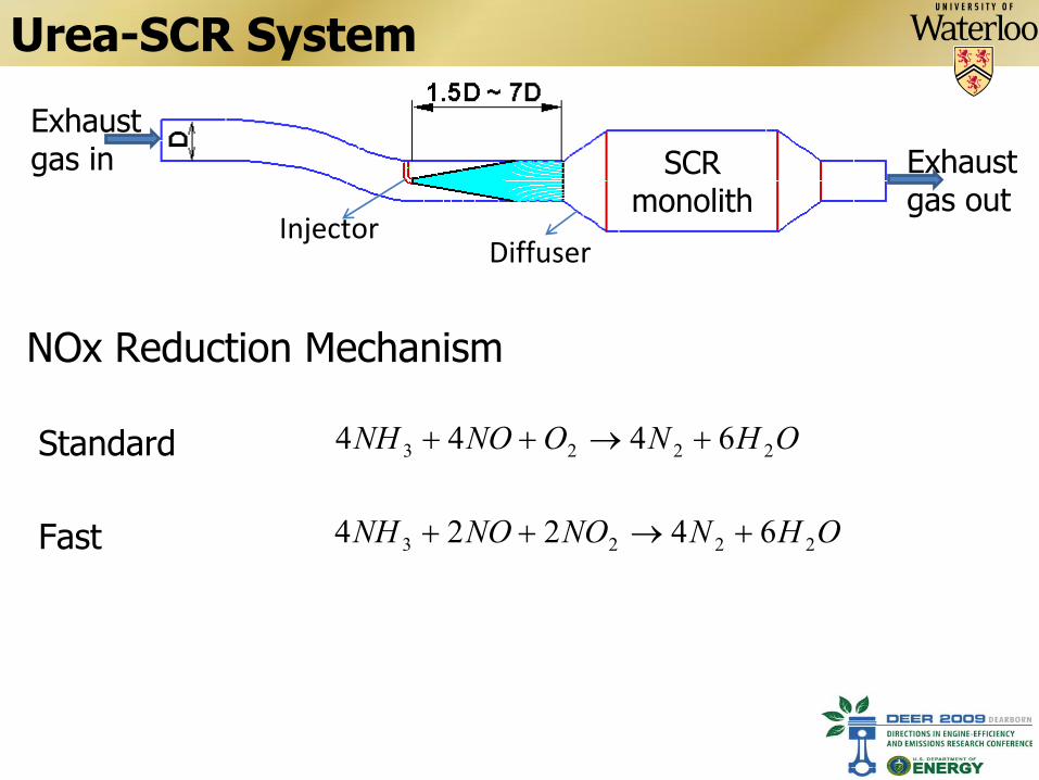
Urea-SCR System
Exhaust gas in Exhaust
gas outSCR
monolithInjector
Diffuser
NOx Reduction Mechanism
OHNONONH 2223 6444
OHNNONONH 2223 64224
Standard
Fast
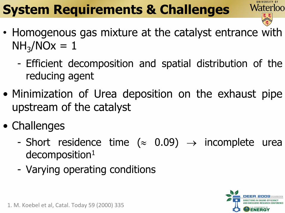
System Requirements & Challenges
•
Homogenous gas mixture at the catalyst entrance with NH3
/NOx = 1
-
Efficient decomposition and spatial distribution of the reducing agent
•
Minimization of Urea deposition on the exhaust pipe upstream of the catalyst
•
Challenges-
Short residence time (
0.09)
incomplete urea
decomposition1
-
Varying operating conditions
1. M. Koebel et al, Catal. Today 59 (2000) 335
Design Criteria
Optimization of the UWS injection/dosing system to maximize the decomposition
efficiency while minimizing wall depositions at varying operating conditions
CFD Role
•
Validated CFD model is required for fast, efficient optimization of the UWS injection and decomposition processes
•
Model requirements-
Predict the interaction between the exhaust gas and UWS spray
-
Account for the interaction between the spray and
exhaust walls
-
Accurately simulate the UWS decomposition process
Developing such a CFD model is the main objective of this work
General Modeling Guidelines•
Eulerian-Lagrangian approach
•
Continuous phase (Exhasut Gas) –
RNG k- model
•
Dispersed phase (UWS droplets)–
Necessary forces: Drag and buoyancy forces
–
Dynamic drag model–
Taylor Analogy Breakup (TAB) model
–
Turbulent dispersion: Stochastic particle tracking
•
Two-way coupling between droplets and gas phase
–
Sensitive to the quality of the turbulence model
•
Regime map for spray/wall interaction
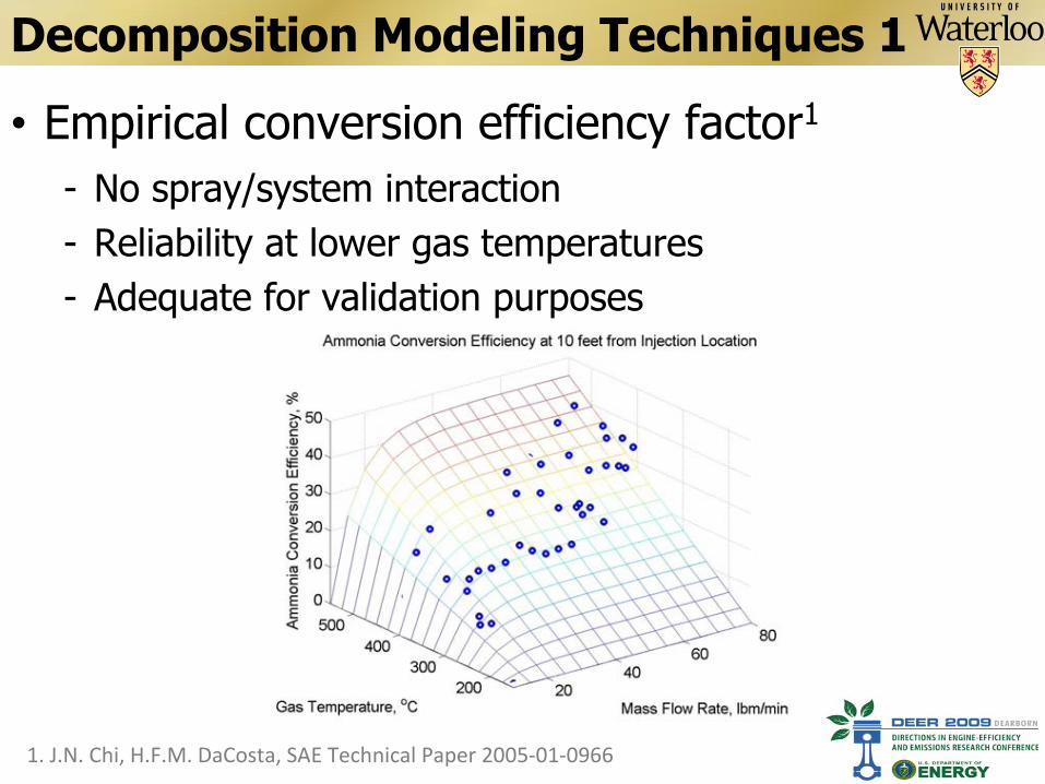
Decomposition Modeling Techniques 1
•
Empirical conversion efficiency factor1
-
No spray/system interaction-
Reliability at lower gas temperatures
-
Adequate for validation purposes
1. J.N. Chi, H.F.M. DaCosta, SAE Technical Paper 2005‐01‐0966
Decomposition Modeling Techniques 2
•
Controlled by turbulent mixing (Eddy- Dissipation Model)1,2
-
Overestimates the conversion efficiency-
Lacks validity assessment
-
Limited to steady state conditions-
Sensitive to the quality of turbulence model’s prediction
-
Relatively fast and inexpensive
1.
S.J. Jeong et al., Environ. Eng. Sci. 25 (2008) 1017 2.
M. Chen, S. Williams, SAE Technical Paper 2005‐01‐0969
Decomposition Modeling Techniques 3
1. H. Ström et al.,
Chem. Eng. J. 150 (2009) 69.
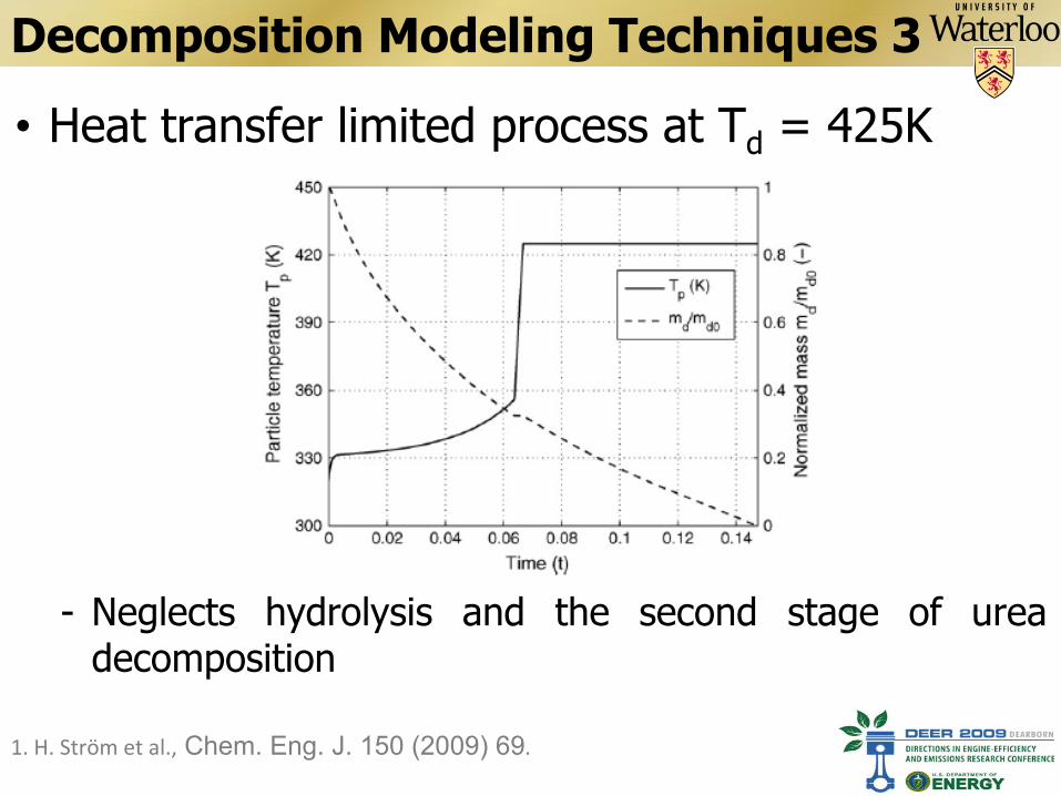
•
Heat transfer limited process at Td
= 425K
-
Neglects hydrolysis and the second stage of urea decomposition

Decomposition Modeling Techniques 4
1. Birkhold et al., SAE Technical Paper 2006‐01‐0643
•
Empirical saturation pressure curve1
-
Hydrolyses is incorporated by Arrhenius expression-
Incorporates spray/wall interaction
dTu ep
399206.12
Decomposition Modeling Techniques 5
1. F. Birkhold et al., Catal. B: Environ. 70 (2007) 119.
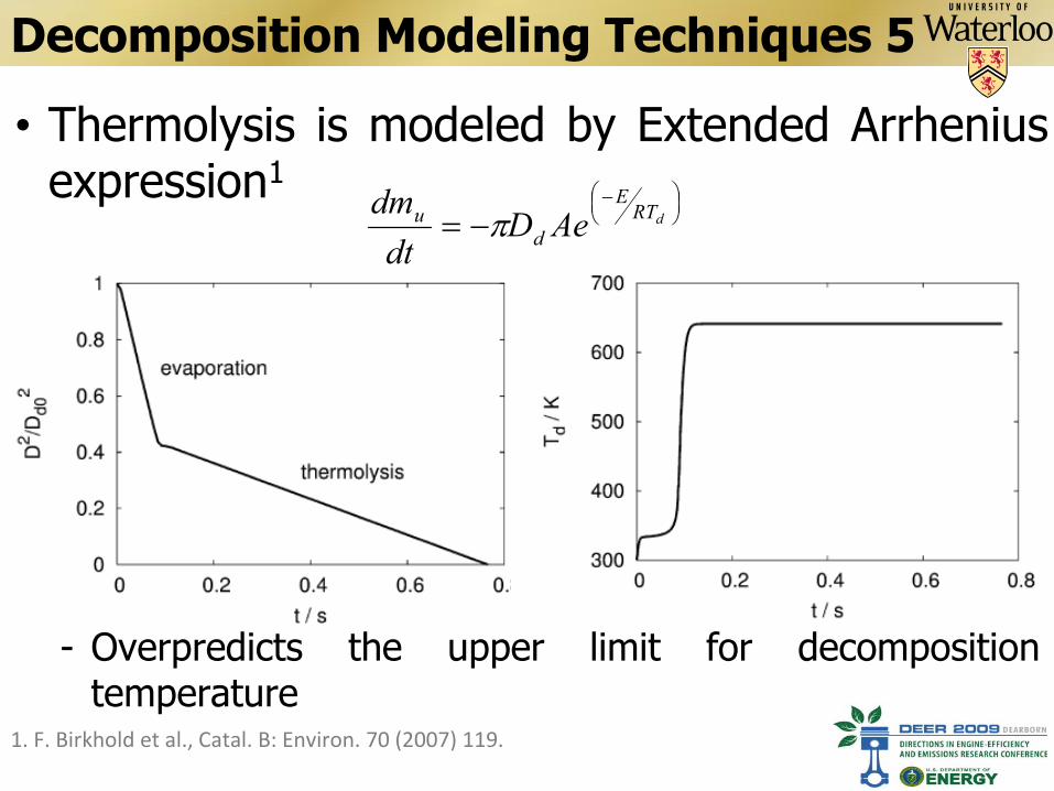
•
Thermolysis is modeled by Extended Arrhenius expression1
dRTE
du AeD
dtdm
-
Overpredicts the upper limit for decomposition temperature
Decomposition Modeling Techniques 5
1. F. Birkhold et al., Catal. B: Environ. 70 (2007) 119
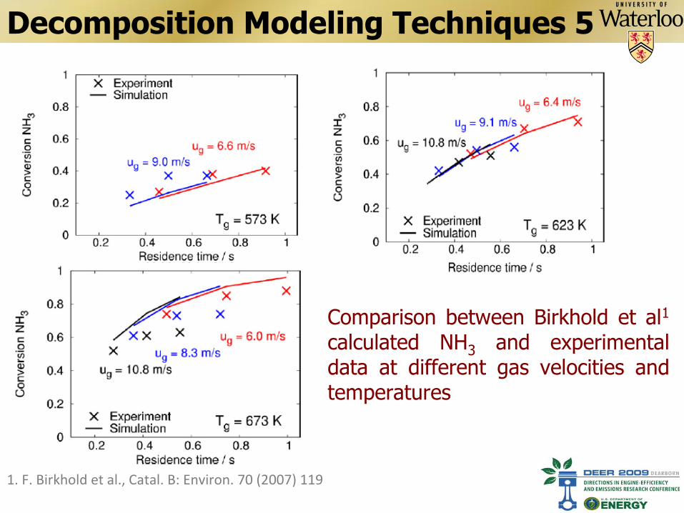
Comparison between Birkhold et al1
calculated NH3
and experimental
data at different gas velocities and temperatures
Decomposition Modeling Techniques 5
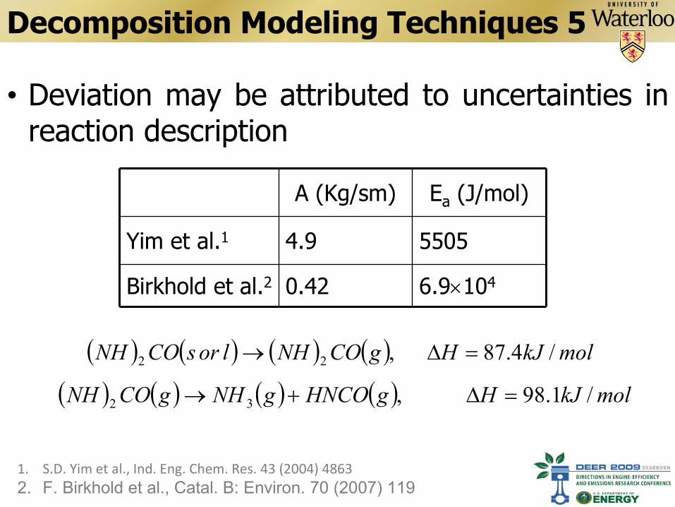
•
Deviation may be attributed to uncertainties in reaction description
1.
S.D. Yim et al., Ind. Eng. Chem. Res. 43 (2004) 48632.
F. Birkhold et al., Catal. B: Environ. 70 (2007) 119
A (Kg/sm) Ea
(J/mol)
Yim et al.1 4.9 5505
Birkhold et al.2 0.42 6.9104
molkJHgCONHlorsCONH /4.87,22
molkJHgHNCOgNHgCONH /1.98,32

Summary & Recommendations
•
The role of CFD modeling to optimize UWS injection and decomposition was presented
•
Results sensitivity to the accuracy of turbulence modeling was reported
•
Various modeling techniques for UWS decomposition process was discussed
•
Modifications proposed (currently under investigations)
–
The use of two layer wall treatment
–
Implementation of the two-step thermolysis process combined with the Arrhenius expression
Acknowledgment
Thank You for Your Attention
•
The work is supported by Auto21