meca0494 : braking · pdf fileintroduction one distinguishes the different categories of...
TRANSCRIPT

MECA0494 : Braking systems
Pierre DuysinxResearch Center in Sustainable Automotive
Technologies of University of Liege
Academic Year 2017-2018
1

MECA0494 Driveline and Braking Systems
Monday 23/10 (@ULG)
AM: Braking performance P. Duysinx (ULg)
Thursday (XXX)
High performance braking systems J. Bouchain (Optesi)
2

Bibliography
T. Gillespie. « Fundamentals of vehicle Dynamics », 1992, Society of Automotive Engineers (SAE)
J.Y. Wong. « Theory of Ground Vehicles ». John Wiley & sons. 1993 (2nd edition) 2001 (3rd edition).
R. Bosch. « Automotive Handbook ». 5th edition. 2002. Society of Automotive Engineers (SAE)
R. Bosch. « Automotive Brake Systems ». R. Bosch Publishers. 1995.
R. Bosch. « Safety, Comfort, and Convenience Systems. Function regulation and components. » Bentley Publishers 2006.
« An introduction to modern vehicle design ». J. Happian-Smith ed. Butterworth-Heinemann. 2002
“Automotive Engineering: powertain, Chassis system, and vehicle body”. D. Crolla ed. Butterworth-Heinemann. 2009 3

Braking system architecture
Introduction
Braking performance
Weight transfer
Optimal braking distribution
Non ideal braking
Brakes devices
Drum brakes
Disk brakes
Braking systems
4

INTRODUCTION
5

Introduction
Brakes are primarily used to decelerate a vehicle beyond its road resistance and the braking drag of the engine
Brakes generally transform the kinetic energy of the vehicle into heat
Brakes can also be used to:
Keep a constant speed
Keep the vehicle at standstill
6

Introduction
One distinguishes the different categories of braking systems
Service brake system: generally decreases the speed while driving
Emergency brake system: has to take over the function of the service brake system when failing
Parking brake system: prevents unwanted motion of the vehicle when parked
Continuous service braking systems: for longer uninterrupted braking and frequent stops for instance in urban heavy vehicles
The service, emergency and parking brake systems directly work on the wheels
The brake elements of the continuous service generally act on the driveline
7

Introduction
A common brake system includes
Control device: pedals / hand-brake lever
An energy source which generates, stores and releases the energy required by the braking system
Transmission device: components between the control device and the brake
The wheel brake or foundation brakes generating the forces opposed to the vehicle motion
8

BRAKE DEVICES
9

Types of brakes
Drum brakes
They used to be the usual brakes some time ago because of their high mechanical advantage and because of their ability to include parking brakes
Disk brakes
Their mechanical advantage is lower and they require higher actuation forces
They require also additional developments to introduce parking brakes
They yield more constant braking forces
10

Drum brakes
The drum spins with the wheel
The flange is fixed with respect to the chassis
http://auto.howstuffworks.com/auto-parts/brakes/brake-types/drum-brake1.htm11

Drum brakes
Brake shoe Drum (inside view)
12

Drum brake
Braking factor is the mechanical advantage between the actuating force (input) and the braking force (output)
It comes
13

Drum brake
The leading shoe A.
The friction force creates a moment that applies the shoe against the drum and the lining pad and thus increases the friction force
The system is self actuated so it yields a high mechanical advantage
This may lead to a brake locking
The trailing shoe B
The friction force tends to create of repulsive moment thus reducing the contact force
The mechanical advantage is lower
It requires a higher actuation force
It is not subject to self locking
Smart combination of trailing and leading shoes and their lining materials may lead to on demand braking factors
14

Drum brakes
The conventional design consists in an internal brake shoe that is applied on the inner surface of the drum.
The usual drum brake includes two shoes in one drum.
According to the type of the clamping force and of the shoe support, the drum brakes are classified in different categories:
Simplex-brake
Duplex-brake
Servo brake
Duo-duplex-brake
Duo-servo-brake
15

Drum brakes
16

Drum brakes
Drum brake simplex-Double brake cylinder-Axle fixed rotation point-One leading shoe and one trailing shoe-Independent of rotation direction
Drum brake duplex- braking with two leading brake shoes or, when backing-up, with two trailing brake shoes
17

Drum brakes
Drum brake servo- Actuation by a single double brake cylinder- Supporting force of the primary shoe is the application force of the secondary shoe- Transmission of the frictional forces of one brake shoe to the other
18
Drum brake with parking brake- Operation of the brake shoes via the wheel brake cylinder-Function of the leading and trailing shoes (the leading shoe is pulled onto the drum, the trailing shoe is pushed away)-Operation of the service brake via the pistons in the wheel cylinder-Operation of the parking brake via a linkage

Drum brakes
19

Drum brakes
20

Disk brakes
Car Motorbike21

Disk brakes: definitions
22

Disk brakes
The disk brakes include
A disk that is connected to the wheel and so it is spinning
A calliper that supports one or several pistons on which are mounted the friction pad. The calliper is fixed with respect to the chassis
There can be one or several pistons
Friction pads made of high friction materials
One can distinguish between
The fixed calliper
The floating calliper or self-adjusting brakes
23

Disk brakes
Disk brakes
Ventilated disk brakes
24

Self adjusting/floating and fixed callipers
Floating calliper disk brake Fixed calliper disk brake
25

Self adjusting and fixed callipers
Floating calliper disk brake Fixed calliper disk brake
26

Self adjusting callipers
Operating principle of floating calliper
27

Floating calliper with adjustment
Adjustment mechanism for a floating calliper
28

Brake pads
The pads must resist to high temperature (about 600°C to 700°C) and to important efforts
The pads are made of high friction materials with friction coefficient in between 0,25 and 0,5
The pads must:
Preserve their high friction coefficient independently of the speed, of the contact pressure, and of the temperature.
Resist to the wear without attacking the disk
Do not produce stick-slip behaviour and noise
Recover their friction properties after being wet
The reduction of the efficiency of pad materials with the temperature is known as the fading. It can conduct to the loss of braking.
29

Disk braking factor
The braking factor of a disk brake
30
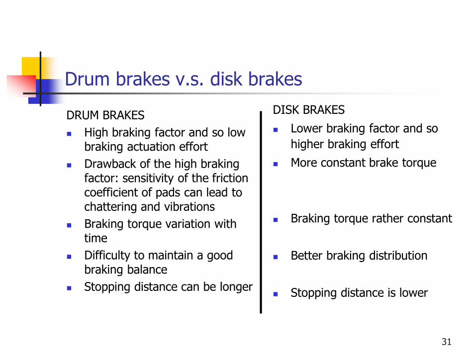
Drum brakes v.s. disk brakes
DRUM BRAKES
High braking factor and so low braking actuation effort
Drawback of the high braking factor: sensitivity of the friction coefficient of pads can lead to chattering and vibrations
Braking torque variation with time
Difficulty to maintain a good braking balance
Stopping distance can be longer
DISK BRAKES
Lower braking factor and so
higher braking effort
More constant brake torque
Braking torque rather constant
Better braking distribution
Stopping distance is lower
31

Drum brakes v.s. disk brakes
Gillespie: Fig. 3.3 : Measurement of brake torque for drum brakes and disk brakes on a braking dynamometer
( , , )b aT f P speed temperature
32

BRAKING SYSTEM
33

Command and actuation of the braking system
In a braking system, one must distinguish:
The braking device itself that is the drum and disk brakes
The command and actuation system that encompasses all the actuation components of the brakes and their command devices
Specifications of the braking system:
Short response time
Smooth and precise control force by the driver
Requires a moderate actuation effort from the driver
Braking distribution between the two wheels of a same axle, whatever could be the orientation and the motion of the wheels
Distribution of the braking forces between front and rear axles as a function of the vertical loads
To be able to stop the vehicle even in case of mal function of the braking circuit
34

Command and actuation of the braking system
Types of a actuation for a braking system:
Mechanical actuation using rigid rods or soft cables (Bowden cables)
Hydraulic actuation
Pneumatic actuation (mostly used on industrial vehicles)
For all vehicles, the ECE regulation prescribes to have two different braking actuation systems on board. The must work independently.
For passenger cars, we have generally:
A mechanical actuation system for the emergency brake and the parking brake called hand brake
A hydraulic braking system for the main braking system
35

Command and actuation of the braking system
Emergency and parking brakes of the Ford Focus 200036

Command and actuation of the braking system
Object of the emergency and parking brake
In case of malfunction, it must be able to stop the vehicle within good conditions (to be defined)
When stopped, the system must be able to maintain the permanent rest conditions
The parking system acts only on a single axle
The emergency and parking braking system can (not mandatory):
Be integrated to the drum brakes
Be integrated in the calipers
Include some independent calipers with their proper set of pads
Be present as a small drum brake system integrated in the disk bowl
37

Command and actuation of the braking system
Mémeteau Fig. 9.3Parking brake integrated in a
disk brake
Mémeteau Fig. 9.4Drum parking brake in
a disk brake
38

Parking brake systems
Generally the mechanical actuation is sufficient for emergency and parking brakes:
The system is independent of the main brake system (hydraulic or pneumatic)
Keep a constant effectiveness even for long parking periods
The drawbacks of the mechanical actuation systems are:
Bad distribution of the braking force on the axles or even between different axles
Bad braking stability during suspension jounce/bounce, wheel steering because the system is based on straight lines mechanical components (cables, rods)
Low efficiency because of the various internal frictions
Risks of seizure
Wear and elongation of the cables
Progressive failure of the cables by progressive failure of the filaments 39

Hydraulic actuation system
An hydraulic command system includes:
A reservoir of hydraulic liquid
A power source or the master cylinder that transforms the brake pedal pressure in hydraulic energy
Receivers: that convert the hydraulic energy into actuating force of the shoes or of friction pads.
Un network of hydraulic pipes connecting the source to the receivers.
40

Basic hydraulic system
Mémeteau Fig. 9.3 Basic hydraulic command system
41

Hydraulic actuation system
Advantages of hydraulic systems:
Perfect repartition of the braking force to the wheels of an axle (the pressure is equal everywhere because of Pascal’s principle)
Possible amplification of the force when using with different piston sections in the master cylinder and in the brake pistons
The pipes can bend and adapt easily the tortuous links
The frictions are very weak
The force amplification mechanism in the braking system results from:
Mechanical amplification, by a system of levers
Hydraulic amplification by using different section ratio
42

Force amplification mechanisms
Lever systems Hydraulic system withdifferent pistons surfaces
43

Master cylinder
44

Master cylinder
Mèmeteau Fig. 9.945

Master cylinder
Components of the master cylinder:
A cylindrical body communicating with the reservoir by an opening in which there is fit slotted elastic pin
At the front end, one or several holes communicating with the pipes to the receiving brake cylinders
A valve for the residual pressure for the drum disks hydraulic circuits
A piston sliding in the cylinder bore
A second ring that insure the sealing with respect to outer
A spring for the recall of the piston that keeps the pressure valve and the primary cups
46

Double braking circuits
Requirement for a double braking circuit:
If the four receiving pistons are connected to a single network of pipes and to the master cylinder,
In case of leakage, the pressure drops everywhere in the pipe network coming to a total failure of the braking system
With a double braking circuit, one increases the safety and the reliability of the system because some braking capability is preserved.
Double braking circuit:
A tandem master cylinder
Two reservoirs
Two pistons (primary and secondary ones)
Two independent networks of pipes47

Double braking circuits
One circuit for two wheels:Parallel or cross lay-out
Front circuit is doubled:Parallel or triangular lay out
Completely doubled circuit
48

Tandem master cylinder
49

Tandem master cylinder
Normal operation of a tandem master cylinder
When the brake pedal is depressed, the rod is pushed and then is pushes the primary piston
The pressure growths in the primary cylinder and the fluid is pushed in the primary circuit.
The pressure in the first cylinder acts on the wall of the second piston, and the pressure growths as well in the secondary cylinder and the fluid is also sent into the secondary circuit.
In case of normal operation, the pressure is the same in the two circuits.
In case of leakage, the system continues working but with a longer displacement of the brake pedal
50

Tandem master cylinder
Working principle of a tandem master cylinder
51

Tandem master cylinder
In case of a leakage, the tandem master cylinder works as following:
Let a leakage in circuit 1. The pressure drops between 1 and 2.
The piston 1 is pushed without any resistance until coming into contact with the face of the piston 2.
When the two pistons are in contact, the system works as a single piston
The circuit 2 continues working but the driver feels a longer displacement of the brake pedal to be actuated. This gives a warning feedback signal to the driver.
52

Hydraulic circuit in case of a leakage
53

Combination valve
The combination valve has three separate functions:
Pressure metering valve
Pressure differential switch
Proportioning valve
54

Pressure metering valve
The pressure metering valve is required for vehicles with both disk brakes in front and drum brakes on the rear axles.
The brake pads of brake disks are remaining nearly in contact with the disks whereas the shoes in drum brakes are extracted from the drum by a spring elements. Thus the time responses of drum brakes is longer than disk brakes.
For braking stability, one has to delay the actuation of the disk brakes on front wheels.
The metering valve is a calibrated valve that allows only a actuation of the front brake disks over a given threshold of pressure
55

Pressure differential switch
The pressure differential switch is a device devoted to warn the driver when there is a pressure drop in one of the circuits
It is made of a small piston whose faces are in contact with the pressure in the two circuits.
A pressure difference conducts to a displacement of the piston which insures a electrical contact to switch on a light for the driver
56

Proportioning valve and pressure limitation
The proportioning valve is a valve that reduces the pressure in the rear brake pistons to prevent the rear wheel locking.
Front
Rear
57

Braking assistance
58

Braking assistance
Braking assistance = device that enables to develop a high pressure in the hydraulic braking circuit with a low or moderate pedal force.
Devices enabling the braking efforts:
Mechanical systems: lever arms
Hydraulic systems: different cross sections of the pistons
Brake assist systems:
Magnification of the effort developed without using mechanisms that requires a increase in the pedal displacement.
59

Braking assistance
Mèmeteau Fig 10.160

Braking assistance
Source of braking assistance:
Create a low pressure using the pressure loss in the admission manifold (for SI engines) and a vacuum pump (for CI engines)
Create a high pressure in the hydraulic fluid developed by a hydraulic pump
Create a high pressure of air developed by a compressor (as in industrial and heavy utility vehicles)
Assistance is obtained by the action of the difference of pressure across the two faces of a membrane
The modulus of the actuating force is the sum of
The braking force on the pedal multiplied by the mechanical advantage of the pedal
The additional force of the assistance device
61

Braking assistance
Mèmeteau Fig 10.462

Braking assistance
Mèmeteau Fig 10.663

Braking assistance
System of braking assistance
Hydrovac
Master vac
64

Vacuum assist unit
The vacuum assist unit is inserted between the brake pedal and the master cylinder.
65

Vacuum assist unit
It includes:
A cylinder a large diameter (in green)
The two chambers are separated by a sliding piston
The piston pushes the actuation rod of the master cylinder
66

Master Vac – working principle
The device uses the low pressure available from engine admission pipes
When the strut is pressed, the air at atmospheric pressure can come into contact with the diaphragm in the right hand side part
The pressure difference between the two sides of the diagram pushes the strut of the master cylinder
As the pressure difference is rather limited, the diameter of the piston must be large to create a significant force
67

Master Vac – working principle
When the pressure on the braking pedal is relaxed, the atmospheric pressure valve is released
The right hand side of the diaphragm is set under depression
The assistance force is cancelled by returning to initial position
68

The check-valve
The check-valve is a one-way valve that allows the low pressure air to leave the master vac low pressure chamber but not to enter into the master vac
So in case of pressure leakage or engine stop, or in case of a pressure leakage not to admit atmospheric air into the chamber
This allows to guarantee that the master is able to work several times and operate safely an assistance force whereas the engine has stopped working
69

Summary
70

Summary: the braking system
71