measuring system implementation - mitutoyo writing by hand to input data to a pc to perform wireless...
TRANSCRIPT

A-2
■ Recording and storing measurement results
Digimatic Mini-Processor DP-1VR
Input tool series
Multiplexer MUX-10F
Prints out measurement data easily, providing the statistical calculation function.
A keyboard signal conversion type Input tool can input measurement data directly into spreadsheet software such as Excel.
RS-232C
Keyboard
USB
4ch
1ch
1ch
USB
A-13
A-12
A-4
U-WAVE
A-8
USB-ITN allows multichannel measurement by combination with USB-PAK.
USB Input Tool Direct: USB-ITN
A-6
Creating Inspection Certificate
Performing statistical process control
Eliminating writing by hand
To input data to a PC
To perform wireless communication
MeasureReport
MeasurLink Real-Time PLUS
Displays in real time GO/NG judgment, process capability, control chart, etc.
A-19
USB-ITPAK
A-6
A-16
■ Using dedicated inspection and quality control software
A form is created easily with Excel.
Commercially avaiable USB hub
Four USB-FSWs +for foot switches
U-WAVE-R
USB-ITN-C
USB-ITN-B
U-WAVE-T
U-WAVE-RU-WAVE-R
U-WAVE-T
A
Measuring System ImplementationThe following introduces system implementation principles showing how measurement results from various Mitutoyo measuring instruments are recorded and used for quality control purposes.
Implementation Step 1 Implementation Step 2
A B C D E F
1 Setting 1 2 3 4 5
2 Dimension X 10.025 10.033 9.964 10.031 10.046
3 Dimension Y 9.982 10.017 10.008 9.996 10.027
4 Dimension H 29.97 30.02 30.07 29.96 30.04
5 External appearance OK OK NG

A-3
Centralizing and analyzing measurement results
MeasurLink
Office
Measurement room
Database Server
Machiningshop floor
Qualitycontrol
CoordinateMeasuring Machine
Vision Measuring System
QM-Data200Digimatic measuringinstruments
Centralizes the inspection results.
The control department can monitor the results from measurement rooms and the shop floor, perform statistical analysis of cumulative data, and issue data forms.
A-16
■ Networking quality control data gathered from various locations
U-WAVE-R
U-WAVE-T
In-plant LAN
AImplementation Step 3

A-4
A
FEATURES•Theinputtoolisaninterfacethatconverts
measurement data to keyboard signals for sending to a PC, enabling you to easily input data from a Mitutoyo measuring instrument, equipped with Digimatic output, directly to cells in off-the-shelf spreadsheet software such as Excel.
•USB,RS-232CandPS/2versionsareavailable to cater for the various PC input requirements.
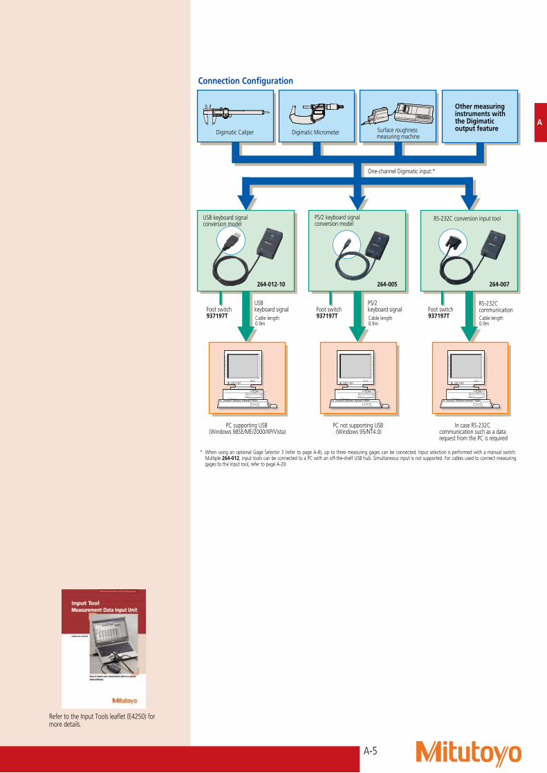
USB keyboard signal conversion modelOrder No.: 264-012-10*Input: Digimatic signal x 1 channelOutput: USB keyboard signal x 1 channel (USB 2.0)Power supply: 5V from the PC bus powerCable length: 0.9mWeight: 61g (including cable)* Applicable to US keyboard, please contact Mitutoyo when using
with other type of keyboard.
PS/2 keyboard signal conversion modelOrder No.: 264-005Input: Digimatic signal x 1 channelOutput: PS/2keyboardsignalx1channelPower supply: 5V from the PC bus powerCable length: 0.9mWeight: 70g (including cable)
RS-232C conversion modelOrder No.: 264-007Input: Digimatic signal x 1 channelOutput: RS-232C x 1 channelPower supply: 12V from the PC bus power Cable length: 0.9mWeight: 91g (including cable)
Common to all modelsDATA switch: Switch life of one million operationsDimensions (W x D x H): 72 x 44 x 23.5mm (main body)
Optional Accessories937179T: Foot switch939039: Gage selector
Input Tool seriesSERIES 264 — Digimatic Gage / PC Data Input Device
264-012-10264-007
264-005
•Measurementscanbemadeevenmoreconveniently by using the optional foot switch instead of the data switch on the instrument.
A-5
A
USB keyboard signal
PC supporting USB (Windows 98SE/ME/2000/XP/Vista)
PC not supporting USB (Windows 95/NT4.0)
In case RS-232C communication such as a data request from the PC is required
PS/2 keyboard signal
RS-232C communication
PS/2 keyboard signal conversion model
Other measuring instruments with the Digimatic output feature
RS-232C conversion input tool
* When using an optional Gage Selector 3 (refer to page A-8), up to three measuring gages can be connected. Input selection is performed with a manual switch. Multiple 264-012, input tools can be connected to a PC with an off-the-shelf USB hub. Simultaneous input is not supported. For cables used to connect measuring gages to the input tool, refer to page A-20.
One-channel Digimatic input:*
USB keyboard signal conversion model
Digimatic Caliper
Foot switch 937197T
Foot switch 937197T Cable length
0.9m Cable length 0.9m
Cable length 0.9m
Foot switch 937197T
264-012-10 264-005 264-007
Digimatic Micrometer Surface roughness measuring machine
Connection Configuration
Refer to the Input Tools leaflet (E4250) for more details.

A-6
USB-ITPAK usage environmentSupported operating systems*
Windows 2000 SP4, Windows XP SP2 or later, Windows Vista, and Windows 7
Supported Excel versions
Excel 2000, 2002, 2003, 2007 and 2010
Hard disk At least 20 MB of free space (required for installation)
CD-ROM drive Required for installationUSB ports At least two ports (for the USB dongle
and USB-ITN)Resolution At least 800 x 600 pixels, and at least
256 displayable colors*•64-bitoperatingsystemsarenotsupported.•ThenaturallanguageselectedinUSB-ITPAKmustbethesameasthatused in the operating system.
A
USB Input Tool Direct: USB-ITNSERIES 264 — Digimatic Gage / PC Data Input Device
This is the same result as that of typing numbers using the keyboard and then pressing Enter.
The input tool directly connects the measuring instrument to a USB port on a computer
Note on using a foot switch with USB-ITNThe USB-ITPAK and USB-FSW options are required (see page opposite).If not using optional software the IT-012U input tool can be used with a foot switch.
Measuring instrumentwith digimatic output
•Supportedoperatingsystems:Windows2000 SP4 Windows XP SP2 or later Windows Vista Windows 7
Computer
USB connector(A type)
Connection port
Existing model: USB input tool
+Cable length: 1 mNo.05CZA662
Cable length: 0.9 mIT-012U No.264-012-10
The input tool has been streamlined by incorporating the USB function into the cable
USB Input Tool Direct for micrometers: USB-ITN-B
Data collection can start immediately after connecting the measuring instrument to a computer
USB-ITN typesEach type of USB-ITN has a unique plug to fit the instrument it is designed for (figures A to G on the left).Just select the type that fits your measuring instrument (USB-ITN-A, USB-ITN-B,...). Detailed specifications, such as part numbers, are shown on page A-20.
Plugs
A
B
C
D
E
F
G
The digimatic plug is connected to the measuring instrument.
The USB plug is connected to a computer.
Cable length: 2 m
The values displayed on the measuring instrument can be sent to the computer just by pressing the data switch.
C
B
F
Because the input tool is automatically recognized as an *HID keyboard device (a standard Windows driver) just by connecting it to a USB port, no special software is required. Patent pending (Japan)*HID (Human Interface Device)
USB foot switch adapter: USB-FSWNo.06ADV384
Major specificationsThe foot switch function can be specified with USB-ITPAK
and used accordingly.1 Data control: Data Request, Data Cancellation, and Data
Skip2 Inputting any character string: Examples - pass , fail , OK,
NG
Total length: 160 mm
FEATURES•Our USB Input Tool Direct has been streamlined into a range of dedicated models for each
type of measuring instrument.•In the same way as the existing model, IT-012U, measurement data can be input to Excel,
Notepad, and other programs just by connecting the input tool to a computer.
Technical Data
2m
USB connector (A plug)
Note: It is recommended to use a commercially available USB hub that has USB certification.
Output specifications: USB 2.0 or 1.1Communication speed: 12 Mbps (full speed)Power supply: USB bus powerWeight: 59gUSB 2.0 certification obtainedComplies with the EU EMC DirectiveIllustration (Example: USB-ITN-A)*Refer to page A-20 for Order No. of the Digimatic gages.
External appearance of USB-FSW
Foot switch (Optional) No.937179T(Cable length: 2m)

A-7
A
USB-ITPAK
This setup and data collection software is used to input data from one or more measuring instruments (connected by way of USB-ITN) to any Excel sheet. (This software package cannot be used with IT-012U.)
Measurement data collection software: USB-ITPAK Order No. 06ADV386
USB dongleUse is only possible with a computer to which the USB dongle is connected.
Major features• Excel input settings: The input destination (a workbook, sheet, or cell), cell-fill direction (right or down), cell-fill interval, and other settings
can be specified.• Measurement method selection: Any of the following three methods can be selected: Sequential measurement, batch measurement, or
individual measurement. (For details, see the measurement examples.)• Data input control: Data can be requested, canceled, or skipped by using mouse buttons, function keys, or foot switch.• Character string input by the USB foot switch adapter, USB-FSW: Any previously specified character string can be input using the foot
switch. Examples: pass or fail• Number of units that can be connected (total number for both USB-ITN and USB-FSW): Up to 20 units can be connected for Windows Vista
or Windows 7, and up to 100 units can be connected for Windows 2000 or Windows XP. However, the above numbers might be less depending on the system configuration.•Data importation time: About 0.2 to 0.3 seconds per unit. However, this value differs depending on the connected measuring instruments
and measurement environment.•Driver software: The VCP (virtual COM port) drivers for USB-ITN and USB-FSW are individually recognized using a built-in COM number.
Details about the usage environment are provided on page 5.
Although measurement data can be simply loaded directly into an Excel spreadsheet just by connecting the instrument and input tool to a computer, using the optional USB-ITPAK software enables time-saving operations and procedures that significantly improve reliability and efficiency.
n USB-ITPAK measurement examples
For this measurement method, one or more measuring instruments (connected by way of USB-ITN) are used to sequentially input one data item at a time according to a procedure stored in advance.
H
Y
X1 A micrometer is used to measure the external diameters X and Y of five workpieces.
2 A caliper is used to measure the length H of five workpieces.
USB-ITN-B
USB-ITN-C
Input character string: OK
Input character string: NG
Data request
Data cancellation
Four USB-FSWs +four foot switches
Commercially available USB hub
Sequential measurement
3 The workpieces are visually examined for problems such as damage and discoloration, and then OK or NG (not okay) is input.
For this measurement method, data is imported in batches from multiple measuring instruments (connected by way of USB-ITN).
For this measurement method, multiple operators make random measurements, and then data is input from the corresponding measuring instruments (by way of USB-ITN) according to individually specified input procedures.
B
AC
Four USB-FSWs + four foot switches
Commercially available USB hub
Data request
Data cancellation
Data request
Data cancellationWorkpieces 1 to 3 Workpieces 4 to 6
Operator 1
USB-ITN-C USB-ITN-C
Operator 2
Batch measurement
Individual measurement
Commercially available USB hubFour USB-ITN-Fs
Data request
Data cancellationHeight A B C D
These types of measurement are made possible by using the USB-ITPAK optional software
Using USB-ITN in Combination with the Optional Spreadsheet Software
Measurement example Measuring the height of a workpiece at the four positions A to D in batches (at the same time) as shown in the figure below
Measurement example Dividing six workpieces into two groups of three, one of which is measured by each of two operators (parallel work)
Measurement example MeasureoutsidediameteratpositionsX/YandlengthH of 5 workpieces sequentially. Finally,performGO/NGjudgmentfortheexternalview(scratches, color shading, etc.) by visual check (see figure at left).

A-8
A
The U-WAVE system enables easy wireless data communication from a measuring tool to a PC using the Digimatic protocol. Measurement workability is improved by eliminating the long and cumbersome data cables usually required and the user-friendly interface allows data to be loaded into any software product that accepts keyboard input, such as Excel* or Notepad.
If the foot switch is connected:Data is sent by one press on the optional foot switch (No.937179T).
(3) Foot Switch Type Connecting Cable
· Registered Design (Japan)(1) U-WAVE-RMajor Specifications of U-WAVE-R
*Detailed information on order No. and conformity standards of wireless communication specification.
Standard U-WAVEPAK setup software
[Specifications of U-WAVEPAK (setup software)]Before using U-WAVEPAK for the first time after purchase, IDs, frequencies, and other settings must be made. The data interface function allows measurement data to be loaded into a PC in Excel, Notepad or other software file that accepts keyboard input.Data can also be input to a program that supports RS-232C serial communication using the virtual COM driver.
1) Operating environmentSupported OS: Windows 2000 Professional (SP4 or higher) Windows XP Home Edition (SP2 or higher) Windows XP Professional (SP2 or higher) Windows Vista Windows 7 64-bit operating systems are not supported.Other information: USB port needed
2) Initial setup procedure(1) Install the U-WAVEPAK (setup software).
Receives data from U-WAVE-T and loads it onto a PC via a USB connection
U-WAVE-R main unit
Refer to the Input Tools leaflet (E4250) for more details.
Specifications of wireless communicationWireless standards: Conform to IEEE802.15.4Wireless communication distance: Approx. 20 m (within visible range)Wireless communication speed: 250 kbpsTransmission output: 1 mW (0 dBm) or lessModulation method: DS-SS (direct sequence spread spectrum) Resistant to interfering signal or noise.Communication frequency: 2.4 GHz band (ISM band: universal frequency)Used band: 15 channels (2.405 to 2.475GHz at intervals of 5MHz) The noise search function can avoid interference with other communication devices.Note: This product is not compatible with the conventional Mu-WAVE, for which communication specifications are different.
Conformity standardsJapanese conformity standards
ARIB STD-T66
European conformity standards
EN 50371:2002EN 300 440-1 V1.3.1EN 300 440-2 V1.1.2EN 301 489-01 V1.6.1EN 301 489-03 V1.4.1
U.S.A. conformity standards
47 CFR Part 15.247:(Subpart :C)47 CFR Part 15,(Subpart :B)
Canada conformity standards
RSS-210 (Issue 7)RSS-Gen (Issue 2)ICES 003 (Issue 4)
Mexican conformity standards
COFETEL DEL 13 DE MARZO DE 2006
Brazilian conformity standards
Resolution 442 and Resolution 506
Note: According to the Radio Regulations the use of this product is permitted in the following countries or areas. This product must not be used in other countries or areas.
Order No. Countries or areas02AZD810D, 02AZD730D, 02AZD880D
Japan, Europe (a total of 32 countries including 27 EU members, 4 EFTA menbers and Turkey), U.S.A. and CanadaMexico (Available for only products labeled with a wireless accreditation label for Mexico)
02AZD810E, 02AZD730E, 02AZD880E
Brazil
Model U-WAVE-ROrder No. 02AZD810*
Power supply USB bus power systemNumber of U-WAVE-R units that can be connected to one PC
Up to 16
Number of U-WAVE-Tunits that can be connected
Up to 100
External dimensions 140×80×31.6mmMass 130g
Measurement data can be input to a standard software package
U-WAVE-R loads data received from U-WAVE-T on to a PC software package via a USB port
U-WAVE-T units transmit data from measuring tools to U-WAVE-R
(3) Standard Type Connecting Cable
Communication distance of approximately 20m (in a good transmission/receptionlocation)
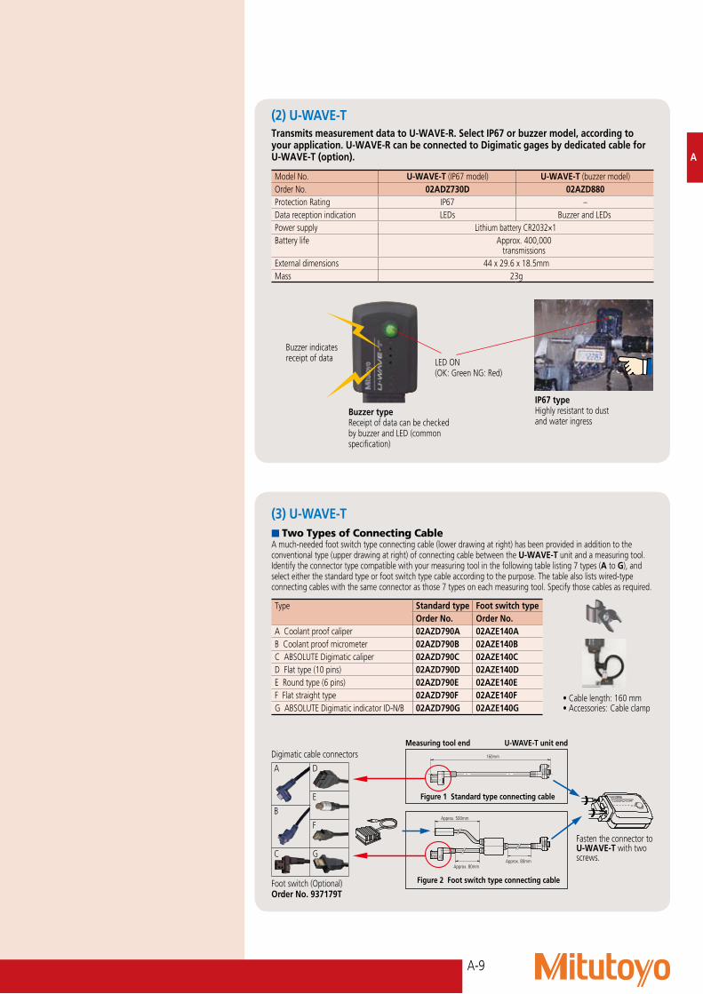
(2) U-WAVE-T
U-WAVEMeasurement Data Wireless Communication System
(2) Connect the U-WAVE-R main unit to the PC with a USB 2.0 cable.
(3) Install the dedicated USB driver and virtual COM driver.
(4) Set IDs and frequencies for U-WAVE-R and U-WAVE-T with U-WAVEPAK.
(5) Press the DATA button of U-WAVE-T once to write settings into U-WAVE-T. Once this procedure has been performed when using U-WAVE-T for the first time, settings are then stored in the main unit memory.
Note: According to the Radio Regulations the use of this product is permitted in the specified countries and regions. This product must not be used in other countries or areas.
(1) U-WAVE-R
(2) U-WAVE-T
A-9
A
Model No. U-WAVE-T (IP67 model) U-WAVE-T (buzzer model)Order No. 02ADZ730D 02AZD880Protection Rating IP67 –Data reception indication LEDs Buzzer and LEDsPower supply Lithium battery CR2032×1Battery life Approx. 400,000
transmissionsExternal dimensions 44 x 29.6 x 18.5mmMass 23g
n Two Types of Connecting CableA much-needed foot switch type connecting cable (lower drawing at right) has been provided in addition to the conventional type (upper drawing at right) of connecting cable between the U-WAVE-T unit and a measuring tool. Identify the connector type compatible with your measuring tool in the following table listing 7 types (A to G), and select either the standard type or foot switch type cable according to the purpose. The table also lists wired-type connecting cables with the same connector as those 7 types on each measuring tool. Specify those cables as required.
Fasten the connector toU-WAVE-T with two screws.
U-WAVE-T unit endMeasuring tool end
Figure 2 Foot switch type connecting cable
Figure 1 Standard type connecting cable
Type Standard type Foot switch typeOrder No. Order No.
A Coolant proof caliper 02AZD790A 02AZE140AB Coolant proof micrometer 02AZD790B 02AZE140BC ABSOLUTE Digimatic caliper 02AZD790C 02AZE140CD Flat type (10 pins) 02AZD790D 02AZE140DE Round type (6 pins) 02AZD790E 02AZE140EF Flat straight type 02AZD790F 02AZE140FGABSOLUTEDigimaticindicatorID-N/B 02AZD790G 02AZE140G
Transmits measurement data to U-WAVE-R. Select IP67 or buzzer model, according to your application. U-WAVE-R can be connected to Digimatic gages by dedicated cable for U-WAVE-T (option).
Buzzer indicates receipt of data
(2) U-WAVE-T
(3) U-WAVE-T
•Cablelength:160mm•Accessories:Cableclamp
Digimatic cable connectors
LED ON(OK: Green NG: Red)
Buzzer typeReceipt of data can be checked by buzzer and LED (common specification)
IP67 typeHighly resistant to dust and water ingress
DATA
Approx. 80mm
Approx. 500mm
Approx. 80mm
DATA
160mm
A D
E
B
F
C G
Foot switch (Optional)Order No. 937179T

A-10
A
U-WAVE-T Instration KitA plastic mounting plate is provided to enable the U-WAVE-T unit and measuring tool to be held together by means of adhesive-backed hook and eye fasteners. This methodmakesattaching/detachingthetoolandU-WAVE-T unit quick and convenient. Batteries can be replaced without needing to detach the tool.
U-WAVE-T Instration KitPart No.02AZE200Accessories•Detachablefasteners:2pieces (mirror-imaged)•Mountingscrews:4pieces (including 2 spares)
n Mounting Drawing
* To avoid damaging the threaded holes in the plastic body of the U-WAVE-T unit, the mounting screws should be tightened only just sufficiently to grip. Repeated removal of these screws should also be avoided for the same reason.
** In order to avoid loss of adhesion, do not allow oil or coolant to come into contact with the bonding surfaces of the detachable fasteners.
Mounting screws, round-head Phillips type, nominal size 2.0x4 (2 pieces)*
Detachable fasteners (adhesive backed)
Connecting cable
U-WAVE-T Mounting holes (2 positions)*
Detachable fastener dimensions
30.5
13
2010
U-WAVE-T
Sumitomo 3M Dual Lock Reclosable Fastener is employed for the removable sheet. This is equivalent to commercially available Scotch 3M Fastener Tape DK-94.
Unit : mm
n The Mounting Plate in UseSuperCaliper CD67-S15PM QuantuMike MDE-25MJ Digimatic Indicator ID-C112XB
Front view Rear view
Example of a custom-order – Support of data request from a PC (Event Drive mode)
This custom-ordered Event Drive enables data requests from the PC end. This system is effective if no operator is in attendance at a measuring tool or if the tool is installed at an inaccessible site. (Data acquisition from a measuring tool such as a Digimatic indicator mounted on a machine or a jig.)
Precautions(1) About battery life: The battery lifespan in the Event Drive mode is shorter than that in the Normal mode (button-drive). Change to the Normal (button-drive) mode after every measurement to extend the battery life span.(2) If using multiple measuring tools: If multiple U-WAVE-T units are connected to one U-WAVE-R unit in the Event Drive mode, a
communication error could result due to conflict between the signals when data is transmitted simultaneously from the U-WAVE-T units since they use the same frequency.
To avoid any transmission conflict, shift the timing of each measurement or provide enough U-WAVE-R units (a maximum of 16 units are connectable) for each measuring tool and set different frequencies (15 channels).
For detailed information, contact the nearest Mitutoyo Sales Department.
Data is automatically transmitted in the Event Drive mode upon change in display value of a measuring tool and thus the latest data is stored in the U-WAVE-R unit.
You do not need to press the Data switch on the measuring tool.
Updated data can be acquired by sending the Data Request command from a PC to the U-WAVE-R unit.
Create a program that supports the data request command as system software by the customer or use Mitutoyo MeasureReport V4.1.
This system needs the custom-ordered U-WAVEPAK that supports the event drive. Purchase the standard models for U-WAVE-T and U-WAVE-R units.
U-WAVE-R
Automatic transmission of updated data
Transmitting the data
request commandReturning updated data
U-WAVE-T
Front view Rear view Front view Rear view
A-11
A
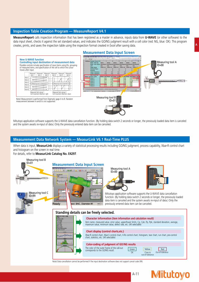
Inspection Table Creation Program — MeasureReport V4.1MeasureReport calls inspection information that has been registered as a master in advance, inputs data from U-WAVE (or other software) to the datainputsheet,checksitagainstthesetstandardvalues,andindicatestheGO/NGjudgmentresultwithacellcolor(red:NG,blue:OK).Thisprogramcreates, prints, and saves the inspection table using the inspection format created in Excel after saving data.
Measurement Data Input Screen
New U-WAVE functionControlling input destination of measurement data
Measured item group 1Cell movement direction: right
Measured item group 2Cell movement direction: down
Possible controls include specification of input items using IDs, grouping of measured items, and specification of the cell to which the cursor moves after input.
Measureditem 1
Measureditem 2
Measureditem 3
Measureditem 4
Measureditem 5
Measureditem 6
Work-1Work-2Work-3Work-4Work-5Work-6
Measuring tool B (channel 01)Measuring tool A (channel 00)
Measuring tool BID=01
Measuring tool AID=00
Measurement Data Network System — MeasurLink V6.1 Real-Time PLUSWhen data is input, MeasurLinkdisplaysavarietyofstatisticalprocessingresultsincludingGO/NGjudgment,processcapability,Xbar-Rcontrolchartand histogram on the screen in real time.For details, refer to MeasurLink Catalog No. E4297.
Measurement Data Input ScreenMeasuring tool AID=00
Measuring tool BID=01
Measuring tool CID=99
Character information (item information and calculation result)
Chart display (control charts,etc.)
Color-coding of judgment of GO/NG results
Itemname,measuredvalue,errorvalue,upper/lowerlimits,Cp,Cpk,Pp,Ppk,standarddeviation,average,maximum value, minimum value, defect rate, etc. (All selectable)
Xbar-R control chart, Xbar-S control chart, X-Rs control chart, histogram, tear chart, run chart, pre-control chart, statistics, etc. (All selectable)
The color of the outer frame of the call-out correspondstotheGO/NGresult. Green Yellow Red
OK
Standing details can be freely selected.
Close to out-of-tolerance
Out-of-tolerance
Note) Measurement is performed from Digimatic gage A to B. Random measurement between A and B is not supported.
Mitutoyo application software supports the U-WAVE data cancellation function. (By holding data switch 2 seconds or longer, the previously loaded data item is canceled and the system awaits re-input of data.) Only the previously entered data item can be canceled.
Note) Data cancellation cannot be performed if the input destination software does not support cancel code (99).
Mitutoyo application software supports the U-WAVE data cancellation function. (By holding data switch 2 seconds or longer, the previously loaded data item is canceled and the system awaits re-input of data.) Only the previously entered data item can be canceled.

A-12
Lower limit
Upper limit
Input data
Number of data
Process capability index
Number of Division of the histogram
Range
Average
Upper control limit (x control)
Lower control limit (x control)
Upper control limit (R control)
Lower control limit (R control)
Mode 0:Records the measurement data and tolerance judgment.
Mode 3:Automatically records the various calculation results to make an X bar R control chart.
Mode 1:Records the measurement data,statistical analysis and histogram.
Mode 2:A "D-chart" can be used to describe measurement data visually. It's also possibleto record the measurement data, statistical analysis and histogram at the same time.
* The user can select large character format (excluding mode 2).
Refer to the DP-1VR leaflet (E4209) for more details.
DP-1VRSERIES 264 — Digimatic Mini-Processor
FEATURES•Thisisapalm-sizedprinterusedtoprint
measurement data from Digimatic gages or to perform statistical analysis.
Order No.264-504**To denote your AC power cable add the following suffixes to the order No.: AforUL/CSA,DforCEE,KforEK,EforBS,FforSAA,NosuffixisrequiredforJIS/100V
Technical DataPrinting method: Thermal line printerPrintingdot: 384dot(8dots/mm)Printingspeed:6.5mm/s(usingACadapter)Printing paper: 48mPrinting line: Approx. 6500 lines for large characters Approx. 12000 lines for normal charactersProcessingcapacity:9999dataitems(mode1/2/3) 100000 data items (mode 0)Printingdata:Measurementdata,GO/±NGjudgment, No.ofdata,Max/minvalue,Range,Average, Standard deviation, No. of defective, Fraction defective, Process capability index, Histogram, D-chart, Control chart generation for Xd-bar and control limit data, date and timeOutput function: Output the measurement data (RS232C) or GO/±NGjudgmentInput timer: 0.25s, 1s, 5s, 30s, 1min, 30min, 60minPower: AC adapter 6VElectric battery: LR6 (alkaline), Ni-Mh (AA size) Battery life: 10 years (clock battery), 10000 lines (1600mA 1time/5sec.usinganickelhydrofluoric battery)Dimensions (W x D x H): 94 x 201 x 75.2mmMass: 390g
264-504
Optional Accessories09EAA084*: RS-232C changing cable (1m, 9 pin)965516*: GO/±NGjudgmentcable937179T: Foot switch *TheRS-232CcableandGO/±NGjudgmentcablecannotbeusedatthesametime.
•TheversatileDP1-VRprinternotonlyprintsmeasurement data, but performs a variety of statistical analyses, draws histograms and D charts and also to performs complicated operations for X bar R control charts.
•EquippedwithRS-232CoutputandGO/NGjudgmentoutputasstandardfunctions, this processor ensures high reliability as an advanced quality inspection machine.
•Thelinethermalprinterenablesfastandquiet printing.
A

A-13
RS-232C (ASCII code)
Press the data switch on the measuring gage.
MUX-10F
Digimatic outputPC
MUX-10F
qw
er
Foot switch
Press the load switch on the front of MUX-10F.
Tool selection switch
DigimaticoutputPC
MUX-10F
Command Measurementdata
qw
er
Digimatic output
PC
Usage ExampleData input using the data switch on the Digimatic gage•Ifthedigimaticgagehasadataswitch,
data is sent to the MUX-10 from the gage, converted to RS-232C and sent out.
Data input using the load switch•Ifthedigimaticgagedoesnothave
a data switch or when simultaneous measurements are performed, the MUX-10 load switch is used to poll data from the measuring gage(s) selected by the tool selection switch(s), converted to RS-232C, and sent out.
•Ifmultiplemeasuringgagesareselectedby the tool selection switch, data is input in the order of channels 1 through 4.
•Optionalfootswitch(937179T) is available for quick data entry.
Data input using the external commands•Datafromaspecifiedmeasuringgage
connected to MUX-10F can be polled (ch 1 - 4) by inputting a command at the PC.
Commands (ASCII) Transfer channels1 (ASCII corde31) CR 12 (ASCII corde32) CR 2 3 (ASCII corde33) CR 34 (ASCII corde34) CR 4A (ASCII corde41) CR 1, 2, 3, 4B (ASCII corde42) CR 1, 2, 4C (ASCII corde43) CR 1, 3, 4D (ASCII corde44) CR 2, 3, 4E (ASCII corde45) CR 1, 2, 3F (ASCII corde46) CR 1, 2G (ASCII corde47) CR 1, 3H (ASCII corde48) CR 1, 4I (ASCII corde49) CR 2, 3J (ASCII corde50) CR 2, 4K (ASCII corde51) CR 3, 4
Multiplexer MUX-10FSERIES 264 — Digimatic/RS-232C Interface Unit
FEATURES•Ameasurementdatatransferdevice,
multiplexer MUX-10F converts incoming Digimatic output measurement data to RS-232C and outputs it to an external device such as a PC.
264-002
•Uptofourmeasuringinstrumentswiththe Digimatic output feature can be connected.
Order No.264-002** To denote your AC power cable add the following suffixes to the order No.: A forUL/CSA,DforCEE,DCforCCC,EforBS,NosuffixisrequiredforJIS/100V
Technical DataData input port: 4 channels for Digimatic gagesData output: Via RS-232C interfaceData output format: RS-232C (D-SUB 9P in connector)Data transmission method: Half-duplex transmissionDatatransmissioncode:ASCII/JISData length: 8 bitsStart bit: 1 bitStop bit: 1 bitParity check: NonSynchronizing method: Start-stop systemData transmission speed: 300bps, 600bps, 1200bps, 2400bps, 9600bps, 19200bpsPower supply: AC adapterDimensions (W x D x H): 91.4 x 92.5 x 50.4mm
Optional Accessory937179T: Foot switch
A

A-14
Digimatic Mini-Processor DP-1VR
Digimatic Indicator
Digimatic Micrometer
Digimatic Caliper
Gage Selector 3
Input Tool
A
Gage Selector 33-channel Switching Box for Data Transmission
Examples of Connections
939039
FEATURES•3Digimaticgagescanbeconnected.•Thechannelswitchisusedtospecifygage
selection for data output.
Order No.939039:
Technical DataConnection: Up to three gagesSignal: Digimatic code formatConnection: BidirectionalExternal dimensions (W x D x H): 100 x 70 x 33mm

A-15
A
48
44.4 91.4
486.
667
96
92 0+0.8
450+0.8
EC CounterSERIES 542 — Low-cost, Assembly Type Display Unit
FEATURES•CompactpanelmountingtypeandDIN
size. It can be easily incorporated into each system.
Order No.542-007**To denote your AC power cable add the following suffixes to the order No.: A forUL/CSA,DforCEE,DCforCCC,EforBS,KforEK,NosuffixisrequiredforJIS/100V
Technical DataCompatible gage: LGD, LGSResolution: 0.001mm, 0.01mmNo. of gage inputs: 1Display: 6-digit LED and a negative [-] signFunction: Preset GO/±NGjudgmentOutput (open-collector): 3-step limit signal, Normal signalExternal control: Preset, Data holdPower supply: Via AC adaptorDimensions (W x D x H): 96 x 48 x 84.6mm DIMENSION
Unit: mm
542-007
A-16
A
Data acquisition & Centralized management of measurement data real-time process control
MeasurLink Real-Time PLUS for Digimatic
Instruments
Inspection report creation
MeasureReport Microsoft Excel®(sold separately)
STATMeasure PLUS for measuring system
products
MeasurLinkProcess Manager
Process monitoring
Gage R&R
MeasurLinkGage R&R
Process analysis
Calibration history management
MeasurLinkProcess Analyzer
MeasurLinkGage Management
MeasurLinkData Base
Program configuration of MeasurLink
Converts to a text file
Basic
Sof
twar
eOp
tiona
l Sof
twar
e
Related Software
MeasurLink programsBasic software MeasurLink Real-Time
MeasurLink Real-Time PLUS (for Digimatic instruments)STATMeasureSTATMeasure PLUS (for measuring system products)
Optional software MeasurLink Process Manager (for process monitoring)MeasurLink Process Analyzer (for process analysis)MeasurLink Gage R&R (for gage R&R calculation)MeasurLink Gage Management (for calibration history management)
Related software MeasureReport (for inspection report creation)
Note: Database software is separately required for network construction.
Recommended operating environmentsStandalone or Client computer system requirements
OS Windows2000SP3orhigher/WindowsXPSP2orhigher/WindowsVista/Windows7
Database Sybase SQL Anywhere*CPU X86:1GHz or moreMemory 1GB or more RAMHard disk 2GB or moreDisplay SVGA or moreOthers CD-ROM drive, keyboard, mouse**
* If used in a network, it is necessary to purchase the database license according to the number of servers and clients.** If used in a network, the parts comprising the network environments such as LAN card, LAN cables and hub are required.
LSL
LCL
CL
UCL
USL
Occurrence of defect
Acce
pted
pro
duct
Past Now Future
Defe
ctive
pr
oduc
t De
fect
ive
prod
uct
Sign found Measures taken
Abnormalities are found based on signs on the control chart
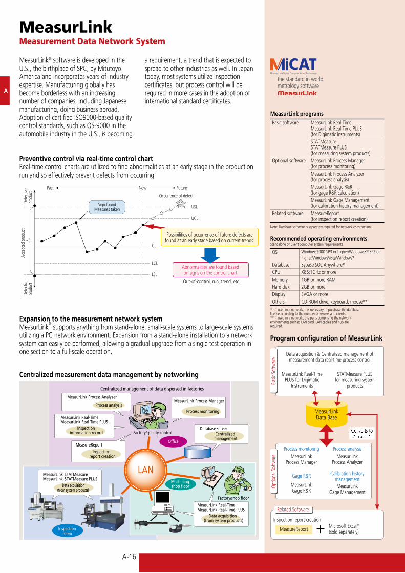
Expansion to the measurement network systemMeasurLink
® supports anything from stand-alone, small-scale systems to large-scale systems
utilizing a PC network environment. Expansion from a stand-alone installation to a network system can easily be performed, allowing a gradual upgrade from a single test operation in one section to a full-scale operation.
Centralized measurement data management by networking
Preventive control via real-time control chartReal-time control charts are utilized to find abnormalities at an early stage in the production run and so effectively prevent defects from occurring.
Possibilities of occurrence of future defects are found at an early stage based on current trends.
Out-of-control, run, trend, etc.
MeasurLinkMeasurement Data Network System
MeasurLink® software is developed in the U.S., the birthplace of SPC, by Mitutoyo America and incorporates years of industry expertise. Manufacturing globally has become borderless with an increasing number of companies, including Japanese manufacturing, doing business abroad. Adoption of certified ISO9000-based quality control standards, such as QS-9000 in the automobile industry in the U.S., is becoming
a requirement, a trend that is expected to spread to other industries as well. In Japan today, most systems utilize inspection certificates, but process control will be required in more cases in the adoption of international standard certificates.

A-17
A
MeasurLinkReal-Time
PLUS
The content of the measurement item balloon display can be configured as desired
Yellow
Close to out- of-tolerance
Red
Out-of-tolerance
Real-time process controlResult of statistical analysis
Character information (item information calculation result)Item name, measured value, error value, upper/lowerlimits,Cp,Cpk,Pp,Ppk,standard deviation, average, maximum value, minimum value, defect rate, etc. (All selectable.)
Chart display (control charts, etc.)Xbar-R control chart, Xbar-S control chart, X-Rs control chart, histogram, tear chart, run chart, pre-control chart, statistical, etc. (All selectable.)
Color-coding of judgment of GO/NG resultsThe color of the outer frame of the call-outcorrespondstotheGO/NGresult
Work No. switch Total judgmentMeasured values and Judgment by workpiece
Narrow-down function to show results for a single workpiece at a glance.
Statistical analysis result displayWiderangeofstatisticalanalysis/displayfunctionsprovidesresults according to characteristics and purposes.
Individual item chart•Xbar-Rcontrolchart (a)•Xbar-Scontrolchart•X-Rscontrolchart•EWMAcontrolchart•Histogram(b)•Runchart(c)•Pre-controlchart(d)•Tearchart(e)
All item chart•Multivariatecontrolchart(f)•Columnindicator(g)•AllitemCpksheet(h)•Multivariatedefectratio
(bar graph)•Managerdisplay
(4 columns x 3 rows)(Histogram, meter, box and
whiskers plot, Cpk)
Measured value•Measuredvaluedatasheet
(Individual item n count x sub Gr)
•Partdatasheet
Statistics•Maximumvalue•Minimumvalue•Average•StandarddeviationS,
Rbar/d2•Processcapability Cp, Cpk, Pp, Ppk•Defectratio•Average±3s /4s/6s etc.
(a) (b)
(c) (d)
(e) (f)
(g) (h)
Digimatic output
Digimatic instrument
MUX-10 Input tool U-WAVE
RS232C output
RS-232 interface
MeasurLink Real-Time PLUS (for Digimatic instruments)MeasurLink Real-Time PLUS transmits measurement data in real time from measuring tools with Digimatic output with RS-232C communication via the interface.
STATMeasure PLUS (for measuring instrument products)STATMeasure PLUS, which resides on the data processing PC, transmits measurement data in real time when the measurement program is executed with inter-program communication (DDE communication).
File outputResults for the specified inspection lot (data, graph, calculation result, etc.) can be output to files in Excel format. (1 sheet is created for each item.)
Select from 10 types of charts (image capture), control charts, and histograms
For statistical processing results, you can select from 30 items such as average, maximum, minimum, Cp, and Cpk.
Measurement data and measurementdate/time
Report outputResults of statistical processing can be output in various types of report.
*By using the optional MeasureReport package, you can create inspection tables in a format previously defined using Excel.
Measurement item report
Graphic window printout
You can easily extract the necessary results and provide them to any department not using MeasurLink. Other file output formats, such as text file and MeasurLink's dedicated format, are also available.
Basic SoftwareMeasurLink Real-Time PLUS (for Digimatic instruments)STATMeasure PLUS (for measuring instrument products)
Green
OK

A-18
A
In-plant LAN
Qualitycontrol office
Listcreation
Calibrationexecution
MeasurLink Process Manager — Process Monitoring Program
MeasurLink Gage R&R — Gage R&R Assessment Program
(1) Selection of evaluation methods(2) Selection of evaluation conditions(3) Input of measurement data
Analysis chart display(1) Gage R&R(2) EV (Equipment Variable)(3) AV (Assessor Variable)(4) PV (Part Variable)
Analysis charts (5 types)
•ThisprogramcanperformgageR&RassessmentasrequiredbyQS-9000inastraightforward manner.
MeasurLink Process Analyzer — Process Analysis Program•Thisprogramsupportsverificationofproblems
through various analyses according to historical information (such as environment, time, machine tool, and operator) about parts and processes using the database in which data has been acquired and accumulated by MeasurLink SPC.
•Thisprogramenablesdifferentialanalysisunderaspecific condition with the filter function and grasp of long-term trend with the combination function.
Powerful search function using an optional item (e.g. next calibration date) as a keyword
•Thisprogramallowsrecordsto be kept of each measuring instrument’s calibration history in order to support proper calibration management. A powerful search function aids effective monitoring of all relevant data.
•Thisprogramcanmonitoreachinspection process state on the network even in the QC office.
•Thisprogramquicklynotifiesthe administrator of a problem that occurs in a process with the alarm function.
MeasurLink Gage Management — Calibration History Management Program
Shop floor/ inspection room
Gage R&R evaluation result display
Report output of evaluation results
Optional Software
Refer to the MeasurLink leaflet (E4297) for more details.

A-19
Order No. Available tool / machine02ARA760B Coordinate Measuring Machines 02ARA781B Vision Measuring Systems 02ARA782B Spin Arms02ARA783B Surftest/Formtracer/Contracer/Roundtest02ARA784B DigimaticSmallTools(Caliper/Micrometer/ Indicator etc)
A
MR-MeasurLink export programConverts selected data from the database collected by MeasurLink and outputs it to a file, starts up Excel and executes macro processing.
Inspection table creation macro programBased on the data file created, the inspection table creation macroaddsOK/NGjudgmentandstatisticalcalculationresults by macro processing, and displays them in Excel inspection table format.
MeasureReportData Conversion Program into inspection Certificates in Excel Format
After the part ID and lot number (date/time)arespecified,fileconversion is performed to create an Excel file.
Data file in the Excel format(Part ID, item ID, design value,
tolerance value, measurement data, measurementdate/time,etc.)
•Maximumvalue•Minimumvalue•Range•Average•Standarddeviation•Cp((UTL-LTL)3/6s)•CpU((USL-Xbar)/3s)•CpL((Xbar-LSL)/3s)•CpUorCpl,whicheverissmaller
•Defectcount(datacount outside tolerances)•Defect%(Defectcount/Data count x 100)•Datacount•Skew•Kurtosis•Coefficientofvariation%
Note: Items in parentheses indicate the Excel functions or calculation methods used.
ODBC database file whose data was
collected by MeasurLink
• Creationofanewformatfile You can create your original format easily by editing the
attached sample format file.• Workpieceshapedisplay The workpiece shape file used in the data acquisition of
MeasurLink is automatically displayed.• Design/tolerancevalues The design and tolerance values registered in MeasurLink
are used as they are.• Errorvaluedisplay Errors in the design values can be displayed.• NGmarking You can add any mark in front of NG data.• Workpiecejudgment OK/NGjudgmentisperformedbywork.
(OK/NGisdisplayed.)• Statisticalcalculation Desired calculation results can be displayed from 15 types
of statistical items.
OnlineRS232C
OnlineRS232C
OfflineFile
conversion•CoordinateMeasuringMachine•VisionMeasuringSystem
•QM-Data•LinearHeight
•MultiplexerMUX-10F•InputTool
OnlineDigimatic
•Digimaticgages
*For file conversion, up to 200 items are convertible.
FEATURES•Datafromameasurementresultfile
generated with a CMM, vision measuring machine or other machine can be output to an inspection table generated with Excel. Data from multiple measuring machines can be combined into a single inspection table (up to 200 measurement items).
•Aninspectiontablecanbegeneratedbyinputting data from the measuring gage with the digimatic output feature via the interface. Calculation results of optical measuring machine, QM-Data200 and the counter values for the X-axis and Y-axis output through RS-232C can be processed in the same way.
•AnoriginalExcelformcanbegeneratedby using an attached sample form as a template and making simple editing (such as copy and paste).
•Thecomputationfunctionisavailablefortolerance judgment, workpiece judgment, statistical calculation and other types of processing at inspection table generation time.
Excel starts up.Macro is executed.
File conversion
A-20
B
B
B
C
C
C
D
D
D
E
E
E
F
F
F
G
G
G
A
A
A
F
A
SPC Connecting Cables
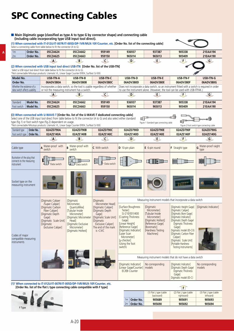
Cable type A Water-proof with switch B Water-proof with
switch C With switch D 10-pin plain E 6-pin round F Straight type G Water-proof raight type
Illustration of the plug that connects to the measuring instrument
Socket type on the measuring instrument
Codes of major compatible measuring instruments
[Digimatic Caliper /SuperCaliper][Digimatic Carbon Fiber Caliper][Digimatic Depth Gage][Digimatic Scale Unit][Digimatic Exclusive Caliper]
[Digimatic Micrometer, QuantuMike][Tubular Inside Micrometer][Digimatic Micrometer Head][Digimatic Exclusive Micrometer][Digimatic Holtest]
[Digimatic Micrometer Head][Digimatic Caliper][Digimatic Depth Gage][Digimatic Scale Unit][Digimatic Exclusive Caliper]The end of the mark is-CX/C
Measuring instrument models that incorporate a data switch
[Surface Roughness Tester] SJ-210/301/400[Coating Thickness Gage][Linear Height][Reference Gage][Digimatic Indicator][Laser Scan Micrometer][μ-checker](Using the foot switch)
[Digimatic Micrometer][Tubular Inside Micrometer][Digimatic Holtest] [Reference Gage][Borematic][Hardness Testing Machines]
[Digimatic Height Gage] [Digimatic Caliper] [Digimatic Bore Gage] [Digimatic Indicator] [DigimaticDepthGage/ Digimatic Thickness Gage] Digimatic model (ID-CX) [Digimatic Carbon Fiber Caliper] [Digimatic Scale Unit] [Portable Hardness Testing Instruments]
[Digimatic Indicator]
Measuring instrument models that do not have a data switch
[Digimatic Indicator] [LinearGage/Counter]EC/EBCounter
No correspondingmodels
[Digimatic Indicator][DigimaticDepthGage/ Digimatic Thickness Gage]Digimatic model (ID-C)
No corresponding models
n Main Digimatic gage (classified as type A to type G by connector shape) and connecting cable (including cable incorporating type USB input tool direct).(1) When connected with IT-012U/IT-007R/IT-005D/DP-1VR/MUX-10F/Counter, etc. [Order No. list of the connecting cable]Select a connecting cable from table below to fit the connector (A to G).
(3) When connected with U-WAVE-T [Order No. list of the U-WAVE-T dedicated connecting cable]Select one of the USB input tool direct from table below to fit the connector (A to G) and also select either standard type (fig.1) or foot switch type (fig.2) dependent on usage. *NotconnectableMitutoyoproducts:LitematicVL,LinearGageCounterEF/EH,SurftestSJ-500.
(2) When connected with USB input tool direct USB-ITN [Order No. list of the USB-ITN] Select a USB input tool direct from table below to fit the connector (A to G).*NotconnectableMitutoyoproducts:LitematicVL,LinearGageCounterEF/EH,Surftest SJ-500.
1m Order No. 05CZA624 05CZA662 959149 936937 937387 905338 21EAA1942m Order No. 05CZA625 05CZA663 959150 965014 965013 905409 21EAA190
Model No. USB-ITN-A USB-ITN-B USB-ITN-C USB-ITN-D USB-ITN-E USB-ITN-F USB-ITN-GOrder No. 06ADV380A 06ADV380B 06ADV380C 06ADV380D 06ADV380E 06ADV380F 06ADV380GWhether the existence of a data switch affects usability
Incorporates a data switch, so the tool is usable regardless of whether or not the measuring instrument has a switch.
Does not incorporate a data switch, so an instrument fitted with a switch is required in order to use the instrument alone. (However, the tool can be used with USB-ITPAK.)
Standard Model No. 05CZA624 05CZA662 959149 936937 937387 905338 21EAA194Foot switch Model No. 05CZA625 05CZA663 959150 965014 965013 905409 21EAA190
Figure 1 Standard type connecting cableFigure 2 Foot switch type connecting cable
Standard type Order No. 02AZD790A 02AZD790B 02AZD790C 02AZD790D 02AZD790E 02AZD790F 02AZD790GFoot switch type Order No. 02AZE140A 02AZE140B 02AZE140C 02AZE140D 02AZE140E 02AZE140F 02AZE140G
(1)’ When connected to IT-012U/IT-007R/IT-005D/DP-1VR/MUX-10F/Counter, etc. [Order No. list of the flat L type connecting cable compatible with F type]
(1) Flat L type (cable backward)
(2) Flat L type (cable rightward)
(3) Flat L type (cable leftward)
1m Order No. 905689 905691 9056932m Order No. 905690 905692 905694
(1)(2)
(3)
F Type
Data switch Data switch Data switch