measuring air 2018
TRANSCRIPT

Measuring Air Velocity - presented by Lonnie Glen, Kice Industries
2/28/2018
1
(and why it is important)Wednesday, February 28, 2018
Presented by Lonnie Glen, Kice Technical Sales
and Quickship Manager
• Air Activated Processing– Grinders
– Granulators
– Hammermills
– Aspirators
• Pneumatic Conveying– Positive Pressure
– Vacuum• (limited to non‐fluctuating loads)
• Dust Control
• Drying/Cooling
Applications for “Air”
Reasons to know how to measure air volumes
• To know if your equipment is operating efficiently– Best operation for the least amount of power
• Sizing new equipment– Dust Collection
– Aspiration
– Conveying
• Important to know when to replace equipment– Blowers, Cyclone, Filters, Fans
• Record‐keeping– Plant operations
– Government agencies

Measuring Air Velocity - presented by Lonnie Glen, Kice Industries
2/28/2018
2
4” OD325 CFM
3” OD180 CFM
4” OD325 CFM
4” OD325 CFM
5” OD520 CFM 6” OD
750 CFM
12” OD2425 CFM
1” w.c.3.5” w.c. 0.7” w.c. 0.5” w.c. 1.3” w.c. 2.5” w.c.
4” w.c.
0.5 “w.c.
10” OD2425 CFM
3” OD 5” OD 6” OD 7” OD 8” OD
Measuring air to determine CFM and STATIC PRESSURE of a dust collection system
Sum total of CFM: 2,425 CFM Total of HIGHEST static pressure run of the system: 14” w.c. SP
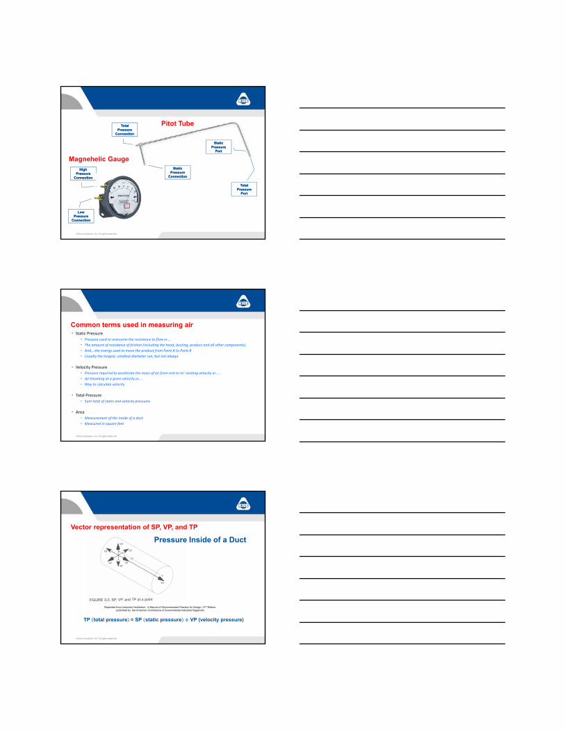
• Pitot Tube• Device used to measure static and velocity pressure
• Air Measuring Kit• Tool set containing components to measure air, including Pitot tube, Magnehelic gauge(s), tubing, drill
bits, charts, calculator, etc.…
• Pressure Differential Gauge• Magnehelic Gauge, Manometer, Spring Gauge, Analog, or Digital device/gauge use to measure pressure
differential
• Velocity • Speed of air, measured as “Feet per Minute” (FPM)
• Volumetric Air Flow Rate• Amount of air typically being moved through the system, measured as “Cubic Feet per Minute” (CFM)
• Duct Velocity• How fast the air, dust or product “flies’” through the duct, measured in FPM• Grain dust typically has minimum of 3400 FPM. Wheat typically conveys at 4200 FPM
Common terms used in measuring air
Typical Air Measuring Kit
Measuring Air Velocity - presented by Lonnie Glen, Kice Industries
2/28/2018
3
Pitot Tube
Static Pressure
Port
Static Pressure
Port
TotalPressure
Port
TotalPressure
Port
Static Pressure
Connection
Static Pressure
Connection
HighPressure
Connection
HighPressure
Connection
Magnehelic Gauge
TotalPressure
Connection
TotalPressure
Connection
Low Pressure
Connection
Low Pressure
Connection
• Static Pressure
• Pressure used to overcome the resistance to flow or….
• The amount of resistance of friction (including the hood, ducting, product and all other components)
• And….the energy used to move the product from Point A to Point B
• Usually the longest, smallest diameter run, but not always
• Velocity Pressure
• Pressure required to accelerate the mass of air from rest to its’ existing velocity or…..
• Air traveling at a given velocity or….
• Way to calculate velocity
• Total Pressure
• Sum total of static and velocity pressures
• Area
• Measurement of the inside of a duct
• Measured in square feet
Common terms used in measuring air
Vector representation of SP, VP, and TP
Pressure Inside of a Duct
Reprinted from Industrial Ventilation: A Manual of Recommended Practice for Design, 27th Edition, published by the American Conference of Governmental Industrial Hygienists
TP total pressure = SP static pressure VP (velocity pressure)
Measuring Air Velocity - presented by Lonnie Glen, Kice Industries
2/28/2018
4
• Air‐to‐Cloth Ratio
• Establishes design capacity of a baghouse filter
• Ratio between the total amount of CFM and total area of the filter bags
• 15,000 CFM / 1,555 sq ft of filter area = 9.65:1 Air‐to‐Cloth Ratio
• Rule of Thumb
• 7‐10:1 for Elevator, Cleaning House, and General Suction
• 7:1 for Secondary Collectors and High Humidity Air Systems
• 5:1 for Filter/Receiver, Centro‐Vacs, and Bin Vents
• Can Velocity
• Velocity measured inside the filter (in the openspace below the bags)
• Interstitial Velocity
• Velocity measured inside the filter (between thefilter bags)
Common Terms
Follow a few basic principles
• Obtain the Velocity of the Air
• Obtain the Area of the duct/tube/pipe at the point of measurement
• Multiply Velocity x Area to determine volumetric flow rate
Basic Formula to determine CFMQ = VA
Q = ACFM (Volume of Air)
V = Velocity (in feet per minute)
A = Tube internal cross-section area (in square feet)
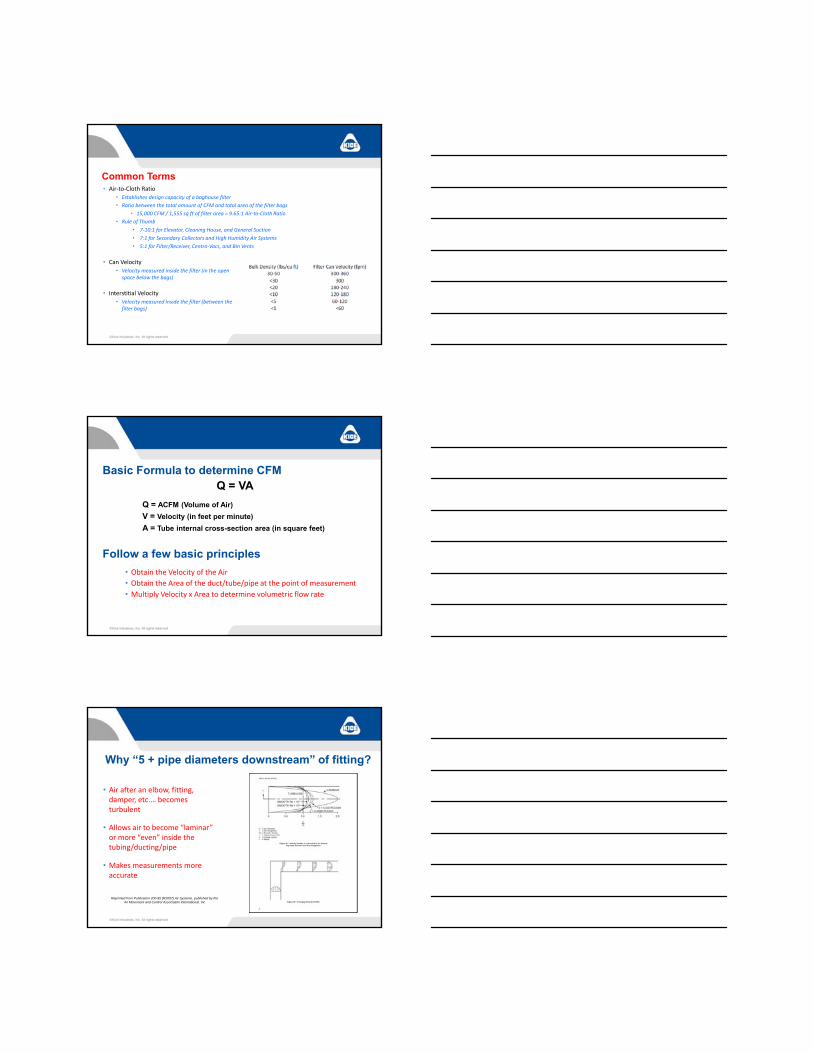
Why “5 + pipe diameters downstream” of fitting?
Reprinted from Publication 200-95 (R2007) Air Systems, published by the Air Movement and Control Association International, Inc
• Air after an elbow, fitting, damper, etc.… becomes turbulent
• Allows air to become “laminar” or more “even” inside the tubing/ducting/pipe
• Makes measurements more accurate

Measuring Air Velocity - presented by Lonnie Glen, Kice Industries
2/28/2018
5
Typical Air Measurement Reading Points
OPTIONALVP READING
INLET SP AND
VP READING
INLET SP AND
VP READING
OUTLET SP AND
OPTIONALVP READING
OUTLET SP AND
OPTIONALVP READING
NOT GOOD LOCATIONSfor Air Measurement Reading Points
Right after
elbow
Right after
elbow
Right after
elbow
To short of
straight run after
elbow
Right after
elbow
Right after
elbow
Turbulent flow
LOCATIONSfor Air Measurement Reading Points
Good location
Good location
Not good location; right after
elbow
Not good location; right after
elbow
Not good location;
difficult to measure
area
Not good location; air
too turbulent
Not good location; air
too turbulent

Measuring Air Velocity - presented by Lonnie Glen, Kice Industries
2/28/2018
6
“By the Book” Method of Measuring Air for accurate air flow measurements
• Safety First
• Select location 10 pipe diameters, if possible, away from dampers, branches, elbows, etc.…
• Drill 2 holes 90‐degrees apart to allow insertion of Pitot tube
• Connect Pitot tube static and/or total pressure connections to gauge
• Need to record temperature and absolute pressure
• Traverse the tube, recording SP (“ w.c.) and VP (“ w.c.) readings at published insertion depths
• Take readings in both planes
• Calculate velocities using each VP reading
• Average the velocities to determine Average Velocity (Vavg) in FPM
• Calculate the Tube Area in square feet at the plane the measurements were taken
• Multiply Velocity by the Tube Area to get CFM
• Safety First
• Select location 5+ pipe diameters, if possible, away from dampers, branches, elbows, etc.…
• Drill hole to allow insertion of Pitot tube
• Connect Pitot tube SP port to gauge or… Put hose perpendicular to the flow over the hole
• If using Pitot tube, center the tube inside the duct
• Record the reading on the gauge
“Reality” Method of Measuring Air forESTIMATED STATIC PRESSURE
• Safety First
• Select location 5+ pipe diameters, if possible, away from dampers, branches, elbows, etc.…
• Drill hole to allow insertion of Pitot tube
• Connect Pitot tube static and total pressure ports to gauge
• Record the VP at the center of the duct using the Pitot tube
• Convert Velocity Pressure (Vp) reading to Velocity (V) FPM
• Refer to chart for Velocity or calculate 4005 x √VP (at STP)
• Multiply the velocity by .9 for 6” OD and smaller duct or by .95 for ducts 8”OD and larger to ESTIMATE Average Velocity (Vavg)
• Determine Tube Area in Square Feet
• In Feet: Area of circle = 3.14 x R2 or .7854 x Diameter2
• In Inches: Area of circle = 3.14 x R2/144 or .7854 x Diameter2/144
– (144 square inches = 1 square foot)
• Multiply Velocity by the Tube Area to get CFM
“Reality” Method of Measuring Air for ESTIMATED air flow measurements

Measuring Air Velocity - presented by Lonnie Glen, Kice Industries
2/28/2018
7
Measuring Static Pressure
“By the Book”– Low pressure connection is
hooked up– Usually the higher reading
gauge– “Zero” out gauge– Hold gauge level– Traverse readings across
tube– Measure in 2 planes– Pitot Tube is into flow
“Reality”– Low pressure connection is
hooked up– Usually the higher reading
gauge– “Zero” out gauge– Hold gauge level– Take center reading– Measure in 1 plane– Pitot Tube is into flow
Velocity Pressure
TP (Total Pressure) – SP (Static Pressure) = VP (Velocity Pressure)
Velocity = 4005 x √VP (at STP)
Reprinted from “Industrial Ventilation, A Manual of Recommended Practice, 22nd Edition”, published by the American Conference of Governmental Industrial Hygienists
“By the Book”– Both connections hooked up– Usually the lower reading gauge– “Zero” out gauge– Hold gauge level– Measure in 2 planes– Pitot Tube is into flow– Traverse readings across tube
Measuring Velocity Pressure“Reality”
– Both connections hooked up– Usually the lower reading gauge– “Zero” out gauge– Hold gauge level– Measure in 1 plane– Pitot Tube is into flow– Read VP at center of duct

Measuring Air Velocity - presented by Lonnie Glen, Kice Industries
2/28/2018
8
Example 1:• VP reading = 1.1• Velocity = 4200 FPM
Example 2:• VP reading = 1.75• Velocity = 5298 FPM
Example 3:• VP reading = 3.60• Velocity = 7599 FPM
Finding Velocity
Reprinted from “Industrial Ventilation, A Manual of Recommended Practice, 22nd Edition”, published by the American Conference of Governmental Industrial Hygienists
Calculation: Velocity = 4005 x √VP (at STP)
Example 1:• Tube = 12” OD and has 0.7854 sq ft area• Velocity = 4200 FPM x .95• Average Velocity = 3990 FPM• 3990 x 0.7854 = Volume of 3,134 CFM
Example 2:• Tube = 12” OD and has 0.7854 sq ft area• Velocity = 5298 FPM x .95• Average Velocity = 5033• 5033 x 0.7854 = Volume of 3,953 CFM
Example 3:• Tube = 12” OD and has 0.7854 sq ft area• Velocity = 7599 FPM x .95• Average Velocity = 7219• 7219 x 0.7854 = Volume of 5,670 CFM
Finding Volume(Q = V x A)
Reprinted from “Industrial Ventilation, A Manual of Recommended Practice, 22nd
Edition”, published by the American Conference of Governmental Industrial Hygienists
Typically, we calculate the Air Velocity from the Velocity Pressure. The calculations are correct for standard air conditions (air with a density of 0.075 lbs. per cubic foot) and based on 70F ambient air temperature, at sea level and a barometric pressure of 29.92” HG.
Velocity readings based on “Standard Air”
For conditions different that “standard air” we need to correct the velocity reading before we calculate to find the velocity and CFM. For this we need to know the Air Density. Typically we need to know the air temperature and elevation to make a correction to the Air Density.
Correction for actual conditions
Calculation: Velocity (V) = 1096.7 x √Air densityVP

Measuring Air Velocity - presented by Lonnie Glen, Kice Industries
2/28/2018
9
Air Density Calculation
Calculation: Velocity (V) = 1096.7 x √Air densityVP
V = 1096.7 x √ of Velocity Pressure divided by the Air DensityV = 1096.7 x √ of 1.0 / .06532V = 1096.7 x √ 15.309V = 1096.7 x 3.9126V = 4291 FPMV(avg) = 4291 x .95 = 4076.5
CFM = V x ACFM = 4076.5 x .7854CFM = 3201
Calculation: Velocity (V) = 4005 x √ VP
V = 4005 x √ of Velocity PressureV = 4005 x √ of 1.0V = 4005 x 1.0V = 4005 FPMV(avg) = 4005 x .95 = 3804.8
CFM = V x ACFM = 3804.8 x .7854CFM = 2988
Assumption:70F and 0’ ASL
Assumption:120F and 1350’ ASL
Known Data compared to Calculated Data
Issue/Problem 1:
Sum total of air going to a dust collector is measured at 200% of original design.
Issue/Problem 2:
Air leg no longer has the capacity it “used to have”.
Issue/Problem 3:
Grinder or Mill is getting too hot.
Result: Short bag lift, High air-to-cloth ratio; dusting out at points, additional maintenance issues; line plugging?
Result: Fan or Air Power Unit is unable to provide adequate static pressure and conveying line cannot handle the load.
Allows you a starting point for checking.
Result: Fan may not be providing enough CFM or static pressure to reduce heat at the mill.
Allows you a starting point for checking.
What changed?What was added?What was taken off line?Something open that is not supposed to be open
Fan belts loose or slipping?Motor over “amping”?Is it the fan rotation?Is the fan speed?Is it fan wear?Is there a choke point?Is there a leak point?Check the Airlock for leakage?Are filters dirty?
Has equipment been relocated?Fan belts loose or slipping?Motor over “amping”?Is it the feed rate?Is it the fan rotation?Is the fan speed?Is there a choke point?Is there a leak point?Check the Airlock for leakage.

Measuring Air Velocity - presented by Lonnie Glen, Kice Industries
2/28/2018
10
Why is this information importantin an “Air System”?
• Make system changes for adequate conveying velocity:– For example, downstream duct area must roughly equal the sum of the area of the upstream ducts. A
system tour can reveal duct branches that may have issues.
• Take proof‐of‐performance airflow and static pressure measurements:– These will show whether you have adequate conveying velocity in all system branches at startup and
provide a reference point to which you can go back if rebalancing is needed.
• Keep records of recent routine system measurements AND follow up when out of “acceptable”:
– Data history may show which parts of the system typically fail first (for example, plugged elbows, blinded filter media, or other component) for corrective action before major events.
Assign trained personnel responsibility for the system:– Allow your personnel the time, tools, and skills to take the data and complete follow‐up actions.
• Increase line size as needed to keep good velocity in the line back to the filter• Reduces resistance & keeps dust in suspension.
• Use lockable dampers or slide gates on each connection point AND MARK FOR REFERENCE• Use for balancing & lockout to keep from changes being made.
• Allow Free Air into the system• Cannot “pull” against a dead head or sealed system & makes use of natural air currents.
• Seal any “leaks” in the system• Will rob the dust collection system of suction to remove dust & many small leaks will add up.
• Purchase and learn to use an Air Measuring Kit• Will let you measure resistance and static pressure, can use to rebalance a system, and gives you some known
data to work with.
• Use care putting Pitot tube in conveying line or heavy dust line.• May clog the small ports in the Pitot tube.
General Good Practices
Dust is in suspension because of correct velocitiesand velocities are correct to minimize wasting HP.
Good design, Good volume, Good velocity

Measuring Air Velocity - presented by Lonnie Glen, Kice Industries
2/28/2018
11
Dust is dropping out (in locations)but system is balanced (at end of system).
BAD design, Good volume, BAD velocity
Dust is NOT in suspension throughout the line• System is not balanced.• Dust build up inside line until area small
enough to carry dust at correct velocity.• Air taking path of least resistance.
Additions without rebalancing
Dust is in suspension (but at higher velocity)• System is balanced (but not correct)• May be picking up good product.• System works but wasting energy (HP).
Deductions without rebalancing
Leaving the drilled hole open• Usually not so large as to effect the system• Can be a point where foreign material can enter
Once you are done measuring the air
Covering the drilled hole• Closes a leak point• Does not allow foreign material to enter
– Self‐tapping screw– Rubber plug– Dab of silicone/caulking– Duct tape/HVAC tape– Air Measurement label/magnet
Marking the drilled hole• Air Measurement label/magnet
– Leaves info for next person

Measuring Air Velocity - presented by Lonnie Glen, Kice Industries
2/28/2018
12
Closing Comments• It is not difficult to take air measurement reading with the correct tools.
• It can help you in dealing with the manufacturer and minimize any downtime.
• The information the air readings provide can:
Benefit product quality
Benefit in product recovery
Extend equipment life
Save energy
Reduce emissions
Reduce housekeeping
Keep the plant running and out of trouble
Thank you for the opportunity to speak today
Contact information: Lonnie Glen; [email protected] / Ph: 316-744-7151