measurement results for radar and wireless system...
TRANSCRIPT

Measurement Results for Radar and Wireless System Coexistence at 3.5 GHz
Jeffrey H. Reed, Charles Clancy, Carl Dietrich, Randal Nealy,
Michael Fowler, Mike Mearns, Mike Shea, Jon Vick
Sponsored by NSWC Dahlgren Division
Overview
• Preliminary 3.5 GHz Radar-Communications Compatibility Tests
• Cognitive Navy Radars and 3.5 GHz Spectrum Sharing
2
PRELIMINARY 3.5 GHZ RADAR-COMMUNICATIONS COMPATIBILITY TESTS
Jeffrey H. Reed
3
Overview of Tests
• LTE communication at 3550-3650 MHz in presence of Naval radar
• Location: Eastern Shore of VA
• Emphasis on proof-of-concept (existence proof)
4
Equipment Used • Rhode & Schwarz CMW500 as eNodeB
• Commercial LTE User Equipment – UE in shielded enclosure
– Dipole affixed to UE as coupler
• Custom frequency translators – 700 MHz to/from 3550 MHz
• Broad-beam directional antennas – C-band TVRO feed horns
– adjustable linear polarization 5
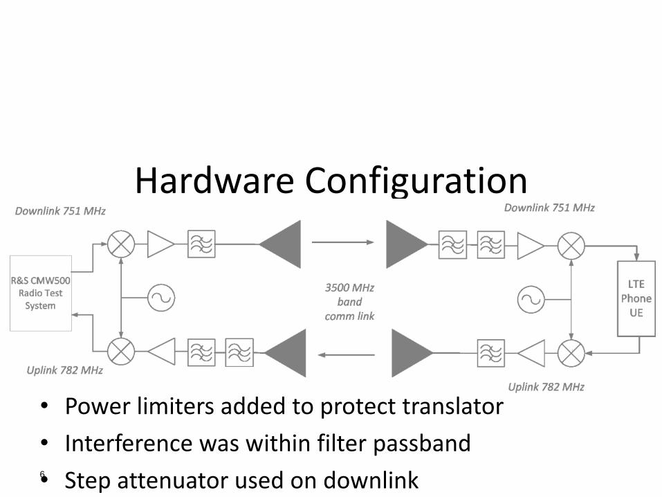
Hardware Configuration
• Power limiters added to protect translator
• Interference was within filter passband
• Step attenuator used on downlink 6

Downlink*
*representative path loss shown
7

Uplink*
*representative path loss shown 8
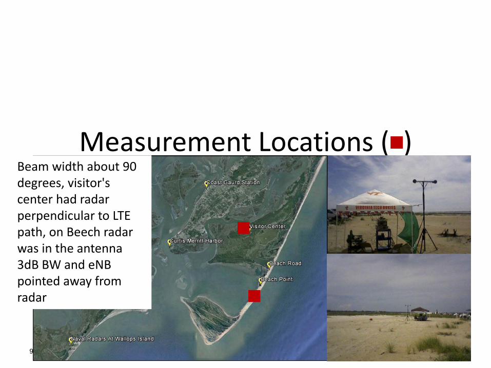
Measurement Locations ( )
9
Beam width about 90 degrees, visitor's center had radar perpendicular to LTE path, on Beech radar was in the antenna 3dB BW and eNB pointed away from radar
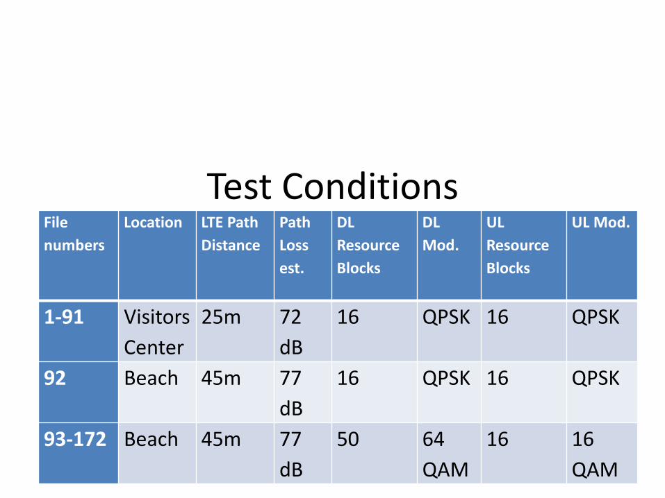
Test Conditions
10
File
numbers
Location LTE Path
Distance
Path
Loss
est.
DL
Resource
Blocks
DL
Mod.
UL
Resource
Blocks
UL Mod.
1-91 Visitors
Center
25m 72
dB
16 QPSK 16 QPSK
92 Beach 45m 77
dB
16 QPSK 16 QPSK
93-172 Beach 45m 77
dB
50 64
QAM
16 16
QAM

LTE and Radar Spectra
11
Peak and instantanus power displaced.
LTE Statistics Collected
• ACKs: packet acknowledgments • NACKs: negative acknowledgments • DTX: discontinuous transmit, UE did not recognize that a packet
was sent • BLER: Block Error Rate • CQI: Channel quality indication • UE Status: e.g., Attached, Connected • Throughput
12

CMW500 Downlink Screen
13

Downlink Throughput at Visitor Center (BPSK, Radar Active)
14
0.0
0.5
1.0
1.5
0 20 40 60
Th
rou
gh
pu
t (M
bp
s)
Attenuation (dB)
Horizontal Vertical

Downlink BLER at Visitor Center (BPSK, Radar Active)
15
0%
20%
40%
60%
80%
100%
0 20 40 60
BL
ER
Transmitter Attenuation (dB)
Horizontal Vertical
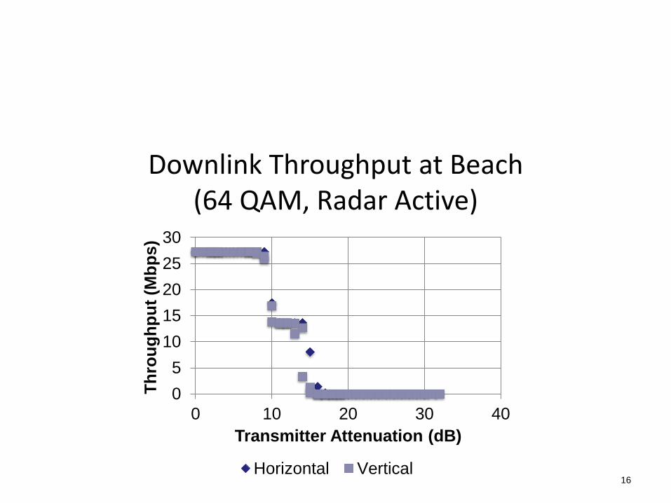
Downlink Throughput at Beach (64 QAM, Radar Active)
16
0
5
10
15
20
25
30
0 10 20 30 40
Th
rou
gh
pu
t (M
bp
s)
Transmitter Attenuation (dB)
Horizontal Vertical

Downlink BLER at Beach (64 QAM, Radar Active)
17
0%
20%
40%
60%
80%
100%
0 10 20 30 40
BL
ER
Transmitter Attenuation (dB)
Horizontal Vertical
Conclusion
• Communication is possible in the presence of operating Naval radars under certain operating conditions
• Power for the LTE system can overcome the radar • Additional work is needed to provide a detailed
feasibility assessment for LTE communication in the 3550-3650 MHz band
18

Future Work
• Bench-top testing using pulse interference with various PRF and pulse width combinations
• Receiver improvements, e.g., band-reject filters
• Field measurements with longer transmit-receive paths
19

Future Work
• Use of omnidirectional antennas • Experimentation with DSA to increase robustness of low-SNR
links • Tests with additional radars that operate in or near the 3500
MHz band • Use stop band filters • Study of implications for use of the band further from coast /
radar locations
20

Acknowledgments
Thanks for assistance during the project and measurements from:
• Bernie Ulfers (NSWCDD)
• Daniel Togni, Richard Canning and Braden Eggerl (Rhode & Schwarz)
• Advice in measurements from Peter Stanforth (Spectrum Bridge) and David Gurney (Motorola Solutions)
21
COGNITIVE NAVY RADARS AND 3.5 GHZ SPECTRUM SHARING
T. Charles Clancy, PhD
22
Cognitive Radar Project Add intelligence to a legacy radar to reduce its impact on WiMAX and LTE infrastructure operating in the 3550 to 3650 MHz frequency band Goal: Fall 2014 field trial demonstrating closed-loop control of Naval radar system to demonstrate reduced impact on WiMAX base stations
23

Cognitive Radar Project
High-Level
Integration
Strategy
24
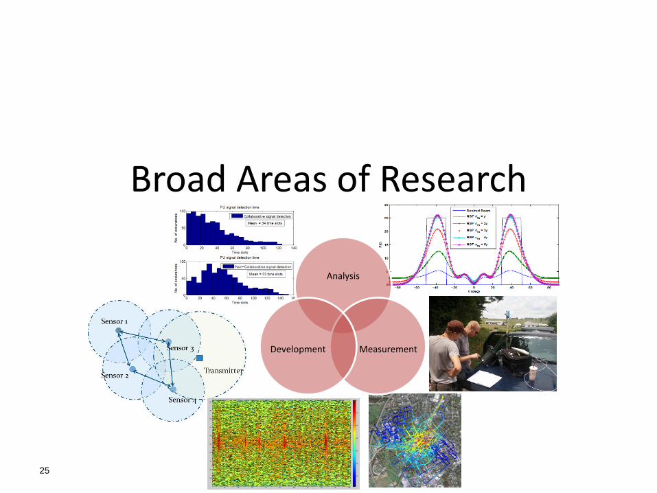
Broad Areas of Research
25
Analysis
Measurement Development

Radar Spectral Mask
26
MATLAB-based waveform model based on measurements
from Navy radars collected in partnership with NSWC
Dahlgren
0 dB
-20 dB
-40 dB
-50 dB
-30 dB
-10 dB
+1
00
MH
z
+2
00
MH
z

Radar Integration User Interface
Real Time Scheduler
Doctrine Messages
Ethernet
Array Control
Clutter Map
Phased Array
Transmit/Re-ceive Signal Processing
RF Analog Systems
Digitized IF Tap
System Strategy Reasoner
Radio Environment
Map
Sensor Signal Processing
Omni Spectrum
Sensor
Radar Control Subsystem
High-Gain Directional Sensing
Low-Gain Omni Sensing
27
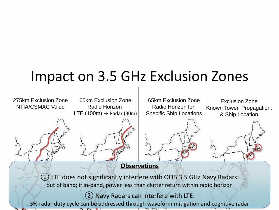
Impact on 3.5 GHz Exclusion Zones
28
65km Exclusion Zone
Radio Horizon LTE (100m) → Radar (30m)
275km Exclusion Zone
NTIA/CSMAC Value
65km Exclusion Zone
Radio Horizon for
Specific Ship Locations
Exclusion Zone
Known Tower, Propagation,
& Ship Location
Observations
① LTE does not significantly interfere with OOB 3.5 GHz Navy Radars: out of band; if in-band, power less than clutter return within radio horizon
② Navy Radars can interfere with LTE: 5% radar duty cycle can be addressed through waveform mitigation and cognitive radar