measurement of seebeck coefficient and conductive … · (x = 0.150.6) thermoelectric...
TRANSCRIPT

Measurement of Seebeck Coefficient and Conductive Behaviors of Bi2Te3¹xSex(x = 0.150.6) Thermoelectric Semiconductors without Harmful Dopants
Mei Fusa1,+1, Naoaki Yamamoto2,+2 and Kazuhiro Hasezaki3
1Interdisciplinary Graduate School of Science and Engineering, Shimane University, Matsue 690-8504, Japan2Faculty of Materials Science, Shimane University, Matsue 690-8504, Japan3Department of Energy System, Institute of Technology and Science, The University of Tokushima, Tokushima 770-8506, Japan
A system for measuring Seebeck coefficient was constructed and applied to Bi2Te3¹xSex (x = 0.150.6) samples without harmful dopants,prepared by mechanical alloying (MA) followed by hot pressing (HP). The constructed thermal contact method system, using single and multiple¦T values, gave Seebeck coefficients of a standard reference material (SRM 3451) at room temperature confirmable as ¹230 « 4 and ¹232 « 1µV/K, respectively. X-ray diffraction patterns and differential scanning calorimetry curves showed that the MAHP-sintered samples ofBi2Te3¹xSex were single-phase Bi2(Te,Se)3-related materials. All the Bi2Te3¹xSex samples were n-type semiconductors. The maximum powerfactor was 1.4 © 10¹3Wm¹1 K¹2 for Bi2Te2.8Se0.2 sintered at 623K. These results indicated that doping with harmful materials of Bi2Te3¹xSexcompounds prepared by the MAHP process is not necessary for carrier control. [doi:10.2320/matertrans.MB201301]
(Received July 1, 2013; Accepted March 12, 2014; Published May 25, 2014)
Keywords: eco-materials, thermoelectrics, Seebeck coefficient, bismuth telluride selenide, n-type
1. Introduction
Bismuth telluride (Bi2Te3)-based alloys have been widelyused as thermoelectric cooling and generating materials.These materials are also eco-materials because they can beused to recover exhaust heat by thermoelectric conversion.The efficiency of a thermoelectric device is expressed by adimensionless figure of merit, which is defined as ZT =¡2·¬¹1T, where ¡, ·, ¬, and T are the Seebeck coefficient,electrical conductivity, thermal conductivity, and absolutetemperature, respectively. ZT is strongly influenced by ¡
because it is proportional to the square of ¡. The measure-ment of ¡ needs to be particularly accurate. The Seebeckcoefficient of a Bi2Te3 standard reference material (SRM3451) has been determined by the National Institute ofStandards and Technology.1,2)
Solid solutions of Bi2Te3 and bismuth selenide (Bi2Se3) areknown to be the best n-type materials for thermoelectricrefrigeration at room temperature.3) Undoped Bi2Te3¹xSexprepared using a melt-growth process shows p-type con-duction for x ¯ 0.2 and n-type conduction for x ² 0.3.4) Theproduction of n-type Bi2Te2.85Se0.15 with excellent thermo-electric properties using a melt-growth process requires theaddition of harmful halide dopants such as CdBr, CdCl2,HgCl2, HgBr2, and SbBr3.3,58) Eco-materials should containas few hazardous substances as possible. In a previous study,undoped Bi2Te2.85Se0.15 compounds without harmful dopants,prepared by mechanical alloying (MA) followed by hotpressing (HP), showed n-type conduction.9,10)
In the present study, a system for measuring Seebeckcoefficients was constructed and applied to Bi2Te3¹xSex(x = 0.150.6) samples without harmful dopants, preparedusing an MAHP process. The thermoelectric properties ofthe resulting samples were investigated.
2. Experimental Procedure
2.1 Construction of system for Seebeck coefficientmeasurements at room temperature
The Seebeck coefficients (¡) were measured using athermal contact system. Figure 1 shows a schematic diagramof the system constructed for measuring Seebeck coefficientsat room temperature. The Seebeck coefficient was estimatedby temperature difference and the thermoelectric motiveforce. The temperature difference was measured betweenconstantan and heat chip. The thermoelectric motive forcewas measured between sample and heater chip. The systemconsisted of a cylindrical direct current (DC) heater with abuilt-in copper heater rod, a copper plate, a constantan block,and the sample or standard Seebeck coefficient material(SRM 3451).1,2) The boundary of this measurement systemassumed the constant heat flux. The heater materials, size,shape and output were determined by the preliminarily FEMsimulation. The simulated criterion of these parameters wasto recover with the original temperature due to high thermaldiffusivity of copper if other materials were contacted toheater chip. If the temperature difference between heater andsamples containing constantan is assumed less than 10K, the
Heater
SRM3451 or sample
Cu plate
constantan
E(ΔT)ΔV
Cu heating rod
Fig. 1 Schematic diagram of system constructed for measuring Seebeckcoefficients at room temperature.
+1Corresponding author, E-mail: [email protected]. Gradu-ate Student, Shimane University
+2Undergraduate Student, Shimane University
Materials Transactions, Vol. 55, No. 6 (2014) pp. 942 to 946©2014 The Japan Institute of Metals and Materials

materials of low thermal diffusivity less than constantan wereconfirmed negligible for the difference of temperature due todifference of these materials. The simulated temperaturedifferences between heater and samples and between heaterand constantan were less than 1%. The size of heater rod hada length of 100 and 12mm in diameter. The size andmaximum output of the cylindrical direct current heater were50mm long and 6mm in diameter and 50W. The constantandimensions were 35mm © 10mm © 2mm. The copper platewas in the square shape of 40mm and the thickness of12mm. The SRM 3451 dimensions were 3.5mm © 2.5mm © 8.0mm. The chip size of copper heater rod wascolumnar 3mm in diameter. The chip had plane contact tosamples. The input power of the copper heater rod was 0.010.5W. The BiTe thermoelectric material SRM 3451 wasused as the reference sample to determine the accuracy ofmeasurements at around room temperature. The SRM 3451sample and the constantan block were placed on the copperplate at temperature controlled room in air. It was assumedthat these materials have the same T1, i.e., room temperature.The copper heater chip was kept at temperature T2 by the DCheater. It assumed that T2 is not influenced with contact tomaterials. Just before the copper heater chip contacts samplesor constantan, the copper heater chip contacted every time thecopper plate and set the null adjustment of DC voltmeter forthe cancellation of copper Seebeck coefficient. The temper-ature difference ¦T = T2T1 between the heater chip and theplate was determined from the contact thermoelectric motiveforce, E, between the constantan block and the copper heaterchip. E was used to calculate ¦T between the constantan andcopper heater chip using the type T (copperconstantan)thermocouple voltage relationship. The differential Seebeckcoefficient ¡ab (V/K) of the sample is given by
¡ab ¼ ¡a � ¡b ¼�V
�Tð1Þ
where ¡a, ¡b and ¦V are Seebeck coefficient of sample orSRM 3451, that of copper and the contact thermoelectricmotive force between the sample or SRM 3451 and the heaterchip, respectively. The null adjustment and E measurementbetween the constantan block and the copper heater chipwere carried out every time before the ¦V measurement. Thedeviations in the measurements of the Seebeck coefficientswere estimated for single ¦T value fixed at one input powerof the copper heater rod and multiple ¦T value changedmany input powers of that.
2.2 Process and evaluationsThe MA samples were Bi2Te3¹xSex; x = 0.150.6. Se
(1 at%) was added to control the carrier concentration forn-type conduction without harmful dopants.
The constituent elements Bi (5N), Te (6N), and Se (5N)were put in a stainless-vessel and milled with silicon nitrideceramic balls, using a planetary ball-mill, for 30 h, at amaximum speed of 180 rpm. The resulting powder waspassed through a 150 µm diameter sieve, and HP sintered at623, 673, and 723K under a mechanical pressure of 147MPain an argon atmosphere. All the powder-processing stepswere performed in an argon atmosphere, with the exceptionthat the HP mold was exposed to air during transportation
between the argon-filled glove box and the HP chamber. Thedimension of sintered compacts were thickness 9mm anddiameter 10mm. The sintered compacts were cut into disksof thickness 0.8mm and diameter 10mm for samples ofSeebeck coefficient and electrical conductivity.
The structures of these MAHP-sintered sample disks wereinvestigated by X-ray diffraction (XRD) using Cu K¡radiation in the Bragg angle range 2ª = 2090°. Differentialscanning calorimetry (DSC) was conducted by heating to950K at a rate of 0.17K/s in a quartz container under anargon atmosphere. The thermoelectric motive force ¦V wasmeasured at a temperature difference ¦T of about 4K, andthermal contact method system was constructed so that thetime of contact between the copper heater chip and thesample disk was more than 120 s. The selected reason ofmeasurement time is obtained constant "V and "T. TheSeebeck coefficients were estimated from eq. (1). Theelectrical conductivity · was measured using a Resitest8340 (Toyo Corporation, Tokyo, Japan) at room temperature,using the van der Pauw method. The performance of thethermoelectric material was estimated using the power factor,P = ¡2·.
3. Results and Discussion
3.1 Evaluation of constructed thermal contact methodsystem
Figure 2 shows the dependence of the thermoelectricmotive force ¦V of SRM 3451 on the contact time betweenthe copper heater chip and SRM 3451 at room temperature;the input powers of the copper heater rod were (a) 0.1W,(b) 0.24W, and (c) 0.48W.
The saturated ¦V was approximately constant after 120 s,and fluctuations were the result of atmospheric changes. The"V of constantan and other samples also were saturatedapproximately constant. These results reveals the back sidetemperature difference between samples and copper platewere not increased. The measurement conditions wereselected so that the contact time between the copper heaterchip and the sample was more than 120 s.
Plots of the input power of the copper heater rod versus thetemperature difference, ¦T, between the heater chip and theplate at room temperature are shown in Fig. 3. The temper-ature difference, ¦T = T2T1, between the heater chip and
(a) p =0.1W
(b) p =0.24W
(c) p =0.48W
2.0
1.5
1.0
0.5
0 200 400 600 800
Time, t /s
The
rmoe
lect
ric m
otiv
e fo
rce,
⏐⏐
Δ V/ 1
0-3
V
Fig. 2 Dependence of thermoelectric motive force (¦V) of SRM 3451on contact time between copper heater chip and SRM 3451 at roomtemperature.
Measurement of Seebeck Coefficient and Conductive Behaviors of Bi2Te3¹xSex (x = 0.150.6) Thermoelectric Semiconductors 943
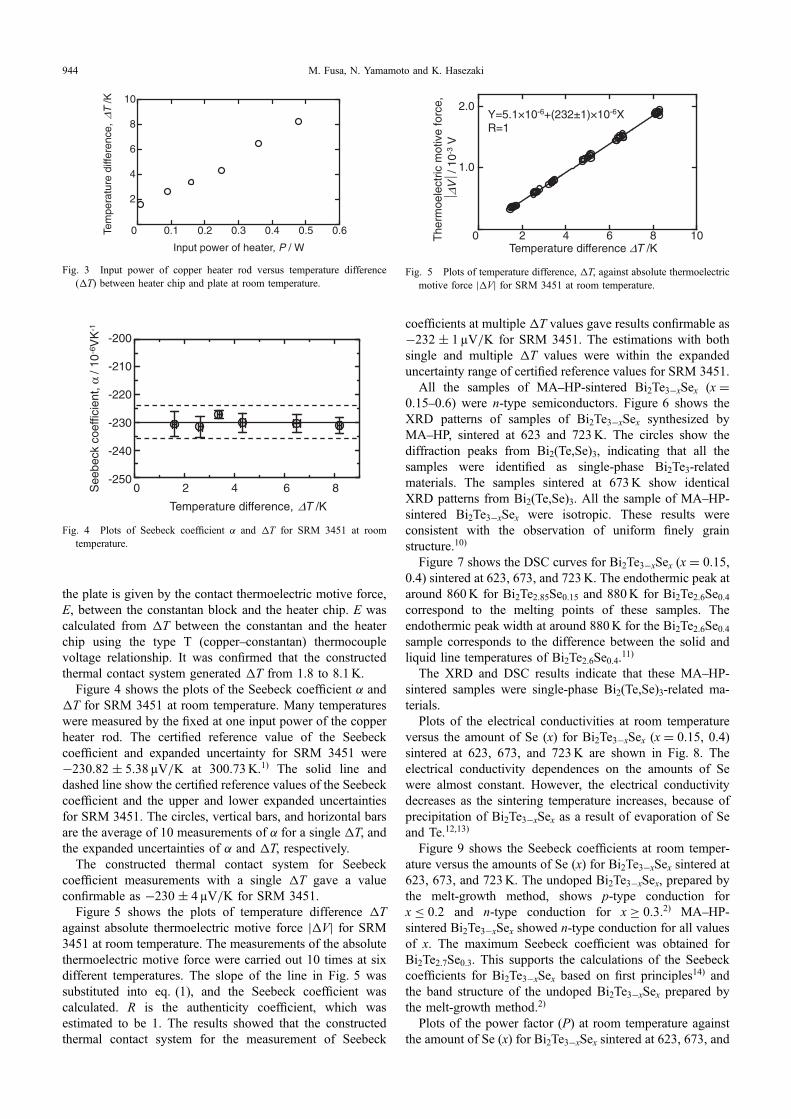
the plate is given by the contact thermoelectric motive force,E, between the constantan block and the heater chip. E wascalculated from ¦T between the constantan and the heaterchip using the type T (copperconstantan) thermocouplevoltage relationship. It was confirmed that the constructedthermal contact system generated ¦T from 1.8 to 8.1K.
Figure 4 shows the plots of the Seebeck coefficient ¡ and¦T for SRM 3451 at room temperature. Many temperatureswere measured by the fixed at one input power of the copperheater rod. The certified reference value of the Seebeckcoefficient and expanded uncertainty for SRM 3451 were¹230.82 « 5.38 µV/K at 300.73K.1) The solid line anddashed line show the certified reference values of the Seebeckcoefficient and the upper and lower expanded uncertaintiesfor SRM 3451. The circles, vertical bars, and horizontal barsare the average of 10 measurements of ¡ for a single ¦T, andthe expanded uncertainties of ¡ and ¦T, respectively.
The constructed thermal contact system for Seebeckcoefficient measurements with a single ¦T gave a valueconfirmable as ¹230 « 4µV/K for SRM 3451.
Figure 5 shows the plots of temperature difference ¦Tagainst absolute thermoelectric motive force «¦V« for SRM3451 at room temperature. The measurements of the absolutethermoelectric motive force were carried out 10 times at sixdifferent temperatures. The slope of the line in Fig. 5 wassubstituted into eq. (1), and the Seebeck coefficient wascalculated. R is the authenticity coefficient, which wasestimated to be 1. The results showed that the constructedthermal contact system for the measurement of Seebeck
coefficients at multiple ¦T values gave results confirmable as¹232 « 1µV/K for SRM 3451. The estimations with bothsingle and multiple ¦T values were within the expandeduncertainty range of certified reference values for SRM 3451.
All the samples of MAHP-sintered Bi2Te3¹xSex (x =0.150.6) were n-type semiconductors. Figure 6 shows theXRD patterns of samples of Bi2Te3¹xSex synthesized byMAHP, sintered at 623 and 723K. The circles show thediffraction peaks from Bi2(Te,Se)3, indicating that all thesamples were identified as single-phase Bi2Te3-relatedmaterials. The samples sintered at 673K show identicalXRD patterns from Bi2(Te,Se)3. All the sample of MAHP-sintered Bi2Te3¹xSex were isotropic. These results wereconsistent with the observation of uniform finely grainstructure.10)
Figure 7 shows the DSC curves for Bi2Te3¹xSex (x = 0.15,0.4) sintered at 623, 673, and 723K. The endothermic peak ataround 860K for Bi2Te2.85Se0.15 and 880K for Bi2Te2.6Se0.4correspond to the melting points of these samples. Theendothermic peak width at around 880K for the Bi2Te2.6Se0.4sample corresponds to the difference between the solid andliquid line temperatures of Bi2Te2.6Se0.4.11)
The XRD and DSC results indicate that these MAHP-sintered samples were single-phase Bi2(Te,Se)3-related ma-terials.
Plots of the electrical conductivities at room temperatureversus the amount of Se (x) for Bi2Te3¹xSex (x = 0.15, 0.4)sintered at 623, 673, and 723K are shown in Fig. 8. Theelectrical conductivity dependences on the amounts of Sewere almost constant. However, the electrical conductivitydecreases as the sintering temperature increases, because ofprecipitation of Bi2Te3¹xSex as a result of evaporation of Seand Te.12,13)
Figure 9 shows the Seebeck coefficients at room temper-ature versus the amounts of Se (x) for Bi2Te3¹xSex sintered at623, 673, and 723K. The undoped Bi2Te3¹xSex, prepared bythe melt-growth method, shows p-type conduction forx ¯ 0.2 and n-type conduction for x ² 0.3.2) MAHP-sintered Bi2Te3¹xSex showed n-type conduction for all valuesof x. The maximum Seebeck coefficient was obtained forBi2Te2.7Se0.3. This supports the calculations of the Seebeckcoefficients for Bi2Te3¹xSex based on first principles14) andthe band structure of the undoped Bi2Te3¹xSex prepared bythe melt-growth method.2)
Plots of the power factor (P) at room temperature againstthe amount of Se (x) for Bi2Te3¹xSex sintered at 623, 673, and
0.1 0.2 0.3 0.4 0.5 0.6
2
4
6
8
10
0Tem
pera
ture
diff
eren
ce,
Δ T /K
Input power of heater, P / W
Fig. 3 Input power of copper heater rod versus temperature difference(¦T) between heater chip and plate at room temperature.
See
beck
coe
ffici
ent,
α / 1
0-6
VK
-1
Temperature difference, ΔT /K
-200
-210
-220
-230
-240
-2500 2 4 6 8
Fig. 4 Plots of Seebeck coefficient ¡ and ¦T for SRM 3451 at roomtemperature.
Temperature difference ΔT /K2 4 6 8 100
2.0
1.0
The
rmoe
lect
ric m
otiv
e fo
rce,
ΔV/ 1
0-3
V
Y=5.1×10⁻⁶+(232±1)×10-6XR=1
⏐⏐
Fig. 5 Plots of temperature difference, ¦T, against absolute thermoelectricmotive force «¦V« for SRM 3451 at room temperature.
M. Fusa, N. Yamamoto and K. Hasezaki944

723K are shown in Fig. 10. The maximum power factor was1.4 © 10¹3Wm¹1 K¹2 for Bi2Te2.8Se0.2 sintered at 623K.These results indicated that doping with harmful materials ofBi2Te3¹xSex compounds prepared by the MAHP process isnot necessary for carrier control.
4. Conclusion
In the present study, a system for measuring Seebeckcoefficients was constructed and applied to Bi2Te3¹xSexsamples without harmful dopants, prepared by MA followedby HP. The results are as follows.(1) The results obtained with the constructed thermal
contact system for measuring Seebeck coefficients from
single and multiple ¦Ts, respectively, were confirmableas ¹230 « 4 and ¹232 « 1µV/K for SRM 3451(¹230.82 « 5.38 µV/K) at room temperature.
(2) XRD patterns and DSC curves showed that the MAHP-sintered samples of Bi2Te3¹xSex (x = 0.150.6)were single-phase Bi2(Te,Se)3-related materials.
(3) All the MAHP-sintered Bi2Te3¹xSex (x = 0.150.6)samples were n-type semiconductors.
Inte
nsity
/ ar
b.un
it
Diffraction angle, 2θ / degree
20 40 60 80
Bi2Te3-xSex
x=0.6
x=0.5
x=0.4
x=0.3
x=0.2
x=0.15
(015
)
(018
) (101
0)(0
111)
(001
5)
(205
)(110
)
(021
0)(1
016)
(111
5)(2
11)
(012
0)(2
110)
(300
)
20 40 60 80
Bi2 (Te,Se)3
x=0.6
x=0.5
x=0.4
x=0.3
x=0.2
x=0.15
Inte
nsity
/ ar
b.un
it
Diffraction angle, 2θ / degree
(a) sintered at 623K
(b) sintered at 723K
Fig. 6 XRD patterns of Bi2Te3¹xSex samples synthesized by MA and HPsintered at (a) 623K and (b) 723K.
0.2 0.4 0.6
1.0
2.0
3.0
4.0
0
Ele
ctric
al c
ondu
ctiv
ity,
σ/1
04 Sm
-1
Bi2Te3-xSex /x
Ts=623KTs=673KTs=723K
Fig. 8 Electrical conductivity at room temperature versus amount of Se (x)for Bi2Te3¹xSex (x = 0.15, 0.4) sintered at 623, 673, and 723K.
400 500 600 700 800 900
Hea
t flo
w Q
, / a
rb.u
nit
Temperature, T /K
(a) Bi2Te2.85Se0.15 Ts:623K
(b) Bi2Te2.85Se0.15 Ts:673K
(c) Bi2Te2.85Se0.15 Ts:723K
(d) Bi2Te2.6Se0.4 Ts:623K
(e) Bi2Te2.6Se0.4 Ts:673K
(f) Bi2Te2.6Se0.4 Ts:723K
Fig. 7 DSC curves of Bi2Te3¹xSex (x = 0.15, 0.4) sintered at 623, 673, and723K.
0 0.2 0.4 0.6-400
-300
-200
-100
0
See
beck
coe
ffici
ent,
α / 1
0-6
VK
-1
Bi2Te3-xSex /x
Ts=623KTs=673KTs=723K
Fig. 9 Seebeck coefficient at room temperature versus amount of Se (x) forBi2Te3¹xSex sintered at 623, 673, and 723K.
Measurement of Seebeck Coefficient and Conductive Behaviors of Bi2Te3¹xSex (x = 0.150.6) Thermoelectric Semiconductors 945

(4) The maximum power factor was 1.4 © 10¹3
Wm¹1 K¹2, for Bi2Te2.8Se0.2 sintered at 623K.These results indicated that doping with harmful materials
of Bi2Te3¹xSex compounds prepared using the MAHPprocess is not necessary for carrier control.
REFERENCES
1) N. D. Lowhorn, W. Wong-Ng, Z. Q. Lu, E. Thomas, M. Otani, M.
Green, N. Dilley, J. Sharp and T. N. Tran: Appl. Phys. A 96 (2009)511514.
2) N. D. Lowhorn, W. Wong-Ng, Z. Q. Lu, J. Martin, M. Green, J. E.Bonevich, E. L. Thomas, N. R. Dilley and J. Sharp: J. Mater. Res. 26(2011) 19831992.
3) H. Scherrer and S. Scherrer: Thermoelectric Handbook: Macro toNano, ed. by D. M. Rowe, (CRC Press, Taylor & Francis Group, 2006)ch.27.
4) D. L. Greenaway and G. Harbeke: J. Phys. Chem. Solids 26 (1965)15851604.
5) H. Kaibe, Y. Tanaka, M. Sakata and I. Nishida: J. Phys. Chem. Solids50 (1989) 945950.
6) K. Uemura and I. Nishida: Thermoelectric Semiconductor and ItsApplications, (Nikkankogyo Shinbunsha, Tokyo, 1988) p. 179 (inJapanese).
7) H. T. Kaibe, M. Sakata and I. A. Nishida: J. Phys. Chem. Solids 51(1990) 10831087.
8) D. Perrin, M. Chitrob, S. Scherrer and H. Scherrer: J. Phys. Chem.Solids 61 (2000) 16871691.
9) M. Fusa, N. Sumida and K. Hasezaki: Mater. Trans. 53 (2012) 597600.
10) M. Fusa, N. Sumida and K. Hasezaki: J. Jpn. Soc. Powder PowderMetallurgy 59 (2012) 121125.
11) L. V. Poretskaya: Inorg. Mater. 23 (1987) 16061608.12) M. Sakata: Thermoelectric Conversion, (Syokabo Publishing Co., Ltd.,
Tokyo, 2005) p. 183 (in Japanese).13) Y. Suga: Thermoelectric Semiconductor, (Makisyoten, Tokyo, 1966)
p. 317 (in Japanese).14) L. Zhao, P. F. Lu, Z. Y. Yu, T. Gao, C. J. Wu, L. Ding and S. M. Wang:
Solid State Commun. 155 (2013) 3439.
0.2 0.4 0.6
1.0
2.0
3.0
0Pow
er f
acto
r,α
2 σ/1
0-3
Wm
-1K
-2
Bi2Te3-xSex /x
Ts=623KTs=673KTs=723K
Fig. 10 Plots of power factor (P) at room temperature versus amount of Se(x) for Bi2Te3¹xSex sintered at 623, 673, and 723K.
M. Fusa, N. Yamamoto and K. Hasezaki946