measurement of interior ballistic ln performance using fm ... · ad us "materielarmy comwad...
TRANSCRIPT

AD
US ARMY"MATERIEL
COMWAD TECHNICAL REPORT BRL-TR-2699 .
:I
MEASUREMENT OF INTERIOR BALLISTIC <-4Ln PERFORMANCE USING FM/FM RADIO
TELEMETRY TECHNIQUES
-James W. Evans 0 ""C
December 1985
. .KOO,
APPROVED FOR PU3UC REI EAS[: DISTRIIUTION UNUMITfO.
US ARMY BALLISTIC RESEARCH LABORATORYABERDEEN PROVING GROUND, MARYLAND
. . .. . . . .. V1 - -

DISCLAIMER NOTICEcr~
THIS DOCUMENT IS BEST
QUALITY AVAILABLE. THE COPY
FURNISHED TO DTIC CONTAINED
A SIGNIFICANT NUMBER OF
PAGES WHICH DO NOTREPRODUCE LEGIBLY.
! 'A Destroy this report when it is no longer needed.
Do not return it to the originator.
V
Additional copies of this report may be obtainedj from the National Technical Information Service,
U. S. Department of Commerce, Springfield, Virginia
....
.. ..: ... --PA
- - , . .
. ,.2-.........
r .. ,
The findings in this report are not to be construed as an officialDepartment of the Army position, unless so designated by other
I. authorized documents.
, I The use of trade names or manufacturers' names in this reportdoes not constitute indorsement of any commercial product.
-U " .P' .. " '. ' .' . : ".' " - , ", •. .'•- . ••'"'• -. _.z: - - . .'' --I . .• .,.
SCCUftITY CLASSIFICATION OF 7TNI PAOE tehaM ON@ ErNW94E ___________________________
REPORT DOCUMENTATION PAGE BE9FORE COMPLEYDIC FORM0.f9PR NUN191 18. GOVT ACCESSION NO- 3- AECIPICNT'S CATALOG NUNUER
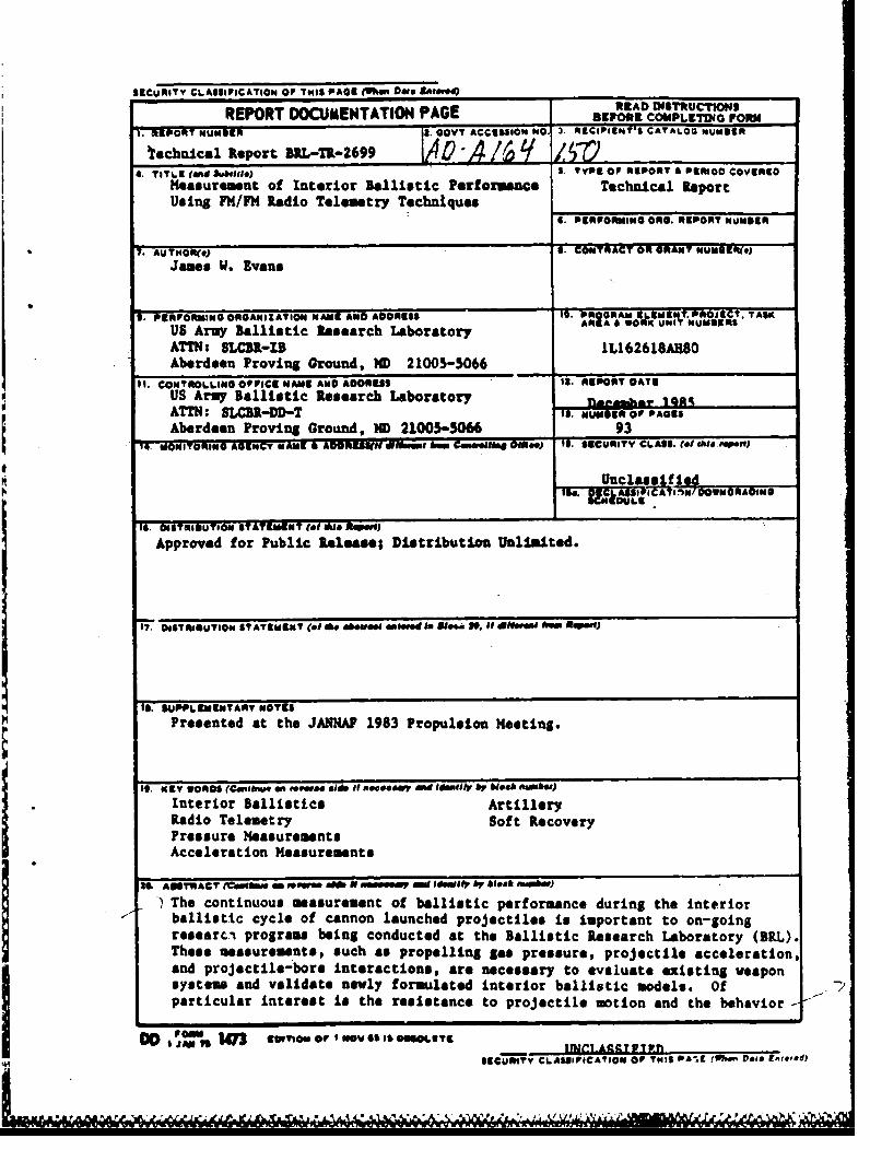
technical Report BRL-TR-2699 -A /' _______________
4. TITLE (Wnd Iubi1t1o) t Type OF RIVORT A POmROD COVIRSOMeasurement of interior Ballistic Perforviance Technical ReportUsing FM/FMf Radio Telemetry Techniques______________
S. PSSPORMING Ono. REP05? NOunSI
7.ATHR* S. CONTRACT Olt GRANT HN9USS(.
9. 11911ORNING ORGANIZATION NANE AND ADDRESS 19 LA PR WOL.09; UNT--R~C TASK
US Army Ballistic Research Laboratory RA"R
ATTN: SLCBR-13 1L,162618AhM8Aberdeen Proving Ground, MD 21005-5066 _____________
11. CONTROLLING OPPICE NAME AND ADORESS 12. AREPORT OAT6US Army Ballistic Research Laboratory 101k%~ATTN: SLCBR-DD-T is. IVUW@ER oP PAGES
Aberdeen Proving Ground, MD 21005-5M6 93
14. WOWITOR1NG AGENCY AmE m egsg 4 ADR buu- 11 . Cma~w F 01*. g) IS. SeCURITY CLASS. (of hi dIeof~I)
tu.. 1 C~SSIICAIINO~WNGmADING
Approved for Public Release; Distribution Unlimited.
17. DIST 4ISUIION ST ATEMENUT (100 8600`01 000Nmd Am 880"a 0-. 40O "Mb ReP.wQ
10. SUPPLEMEMYANY NOTES
Presented at the JAXNA 1983 Propulsion Meeting.
It, Kay WORDS (C.,einu. an, w. mf Old It sot#**" dd $Wldffl'S by 610h ftmhw)
Interior Ballistics ArtilleryRadio Telemetry Soft RecoveryPressure Measurements
j Acceleration Measurements
ES& AssrRACT M~A - m 00w 0 t0000MW eOnIatP by 610" nmmee)
ballistic cycle of cannon launched projectiles is important to on-going
researc.i programs being conducted at the Ballistic Research Laboratory (SaL).The#* measurements, such as propelling gas pressure, projectile acceleration,and projectile-bore Interactions, are necessary to evaluate existing weaponsystems and validate newly formulated interior ballistic models. Ofparticular interest is the resistance to projectile motion and the behavior
DO , 147 ~mt@ @Pt MO 555O~e~,E~g SECURITY CL AS91I PC AY90 OF T"IS PA*. rt" Vol&~ Dtmof.Ied)
NAQ 6U -_4'G 4-4- Q 6W*- & 6- A g -W N r -0 ,. ki'

UNCLASSIFIED1sCUMITY CLAWSIICATIOi OP ThIS PA@UtWS DOS intmo
Abstract (cont):
of the projectile during the engraving process. The measurement of forctson projectiles and projectile-bore interactions requires that transducers belocated on-board the projectile. In-bore measurements of ballisticperformance are made at the BRL using an FP/Ft4, S-band telemeter.
Standard artillery projectiles are modified and instrumented withtelemetry transmitting systems. These projectiles are test fired and dataextracted via the real time telemetry link. The projectile systems areexpendable free-flight rounds and chose modified for recovery in the BRLLarge Caliber Soft Recovery System (LCSRS). The instrumentation package forthe recoverable rounds is configured so it can be removed from theprojectile, recalibrated after exposure to the launch environment, and usedon subsequent rounds.
The instrumentation on-board the projectile measures the base pressure,axial acceleration, strain, and on some projectiles, tangentialacceleration. The axial acceleration is used to derive the interiorballistic trajectory. The base pressure and axial acceleration are used toderive the resistive pressure profile. The resistive pressure is defined asthe sum of all frictional forces acting on the projectile divided by thecross-sectional area of the bore. It is calculated using the force balanceequation applying Newton's Second Law. The resistive pressure, when plottedversus displacement, shows the forces during engraving and the down tubetravel.
This report discusses the technique used to acquire the on-boarddata. It includes a description of the telemetry transmitting system, thetelemetry receiving system, calibration procedures, and projectilemodifications. Representative data acquired from test firings are presentedfrom .s number of instrumented projectiles both free-flight and into theLCSRS.
UNCLASSIFIED
9SCURITY CLASSIPICATION 0 T
HIS PAGI'W?,en t)r& tM.e(Ed)

TABLE OF CONTENTS
Page
LIST OF ILLUSTRATIONS ........................................ 5
1. INTRODUCTION .................. ...... * ................ 9
ItI TELEMETRY TRANSMITTING SYSTEM ............ . ...................... 11
A. Piezoelectric Transducers ............................... 13
!B. Constant Current Source ................................. 14
C. Analog Amplifier ....... ................... 15
ýD. Voltage Controlled Oscillator ............ ................ 15
E. Limitter Circuit ....... ....................... 15
•F. Mixer Amplifier ..................... *0............ 0........ 15
S~G. Transmiter ...... ............................. 16
H. Antennas .......... .............. 1.. .... . * . *...... ... 16
S1. Strain Measurements .................... . .............. 17
J. Power Supply ......... ........ 19
III. TELeMETRY RECEIVING SYSTEM ................................... 20
A. Radio Frequency Receiving System .......................... 22
B. Data Discriminating System .............................. 22
IV. TELEtETRY SYSTEM PARAMETERS .................................. 23
V. TELEMETRY SYSTE CALIBRATION ................. ................ 26
A. Piezoelectric Channel Calibration,Transmitting System ..................................... &.*a** 26
B. Strain Channel Calibration,Tranomitting System ................................ *........ .... 28 r
C. Receiving System Calibratioti ............... 29
VI. R~ECORDIN4G AND DATA KEDUCT10N ................................. 30 i
VII. TEST PROJECTILES ............. *........ .... ... ............. 32
A. 155-mm, N•II01 Free-Flight Projectiles .................... 33
iAv.dbaiity Codeg
3 1Avail andjor
TABLE OF CONTENTS (CONT'D)
Page
B. Instrumented/Recoverable 155-mm,M1O1 Projectiles ....... ............ * ....... ........... 34
VIII. FIRING PROGRAMS .............................................. 38
A. Free-Flight Projectiles ............ . . ... .. . ........ ...... 39
b. Soft Recovery of Instrumented Projectiles ................. 39
c. Recoverable Projectiles ................................... 41
IX. RESULTS AND DATA REDUCTION ................................... 42
A. Measured Projectile Acceleration .......................... 42
B. Measured Base Pressure .*... .. ...... ......... .......... 46
C. Resistive Pressure Profile ................................ 46
D. Angular Acceleration Measurements ......................... 57
X. CONaLUSIONS .. ........ ........... 74
XII. ACM'NOWLEDGMENTS ................................................ 81
REFERENCES.............................................. 83

LIST OF ILLUSTRATIONS
Figure Page
I Standard FM/FM TelemetrySystem............................... 10
2 Telemetry Transmitting System, Block Diagram ................. 12
3 Telemetry Components ................................. 12
4 Telemetry Transumitting Subsystems ............................ 13
5 Piezoelectric Transducer, Circuit Diagram .................... 14
6 Slot Antenna ......................... ... ... . ... e... 18
7 Dipole Antenna .......................................... 18
8 Strain Measuring Syctem, Constant Voltage .................... 19
9 Strain Measuring System, Constant Current .................... 20
10 Shorting Bar .......................................... 20
ii Telemetry Receiving System, Block Diagram .................... 21
12 Frequency Modulation System, Block Diagram ................... 25
13 Typical Video Spectrum, a - 0.711 .......................... 25
14 Pressure Channel Calibration ................................. 27
15 Acceleration Channel Calibration .............................. 28
16 Strain Channel Calibration 29
17 Receiving System Calibration ................................. 30
18 Ballistic Data Acquisition System, Block Diagram ............. 31
19 InsLrumented Free-Plight 155-, MIOl Projectile ............. 33
20 155-mm, MIOI Projectile Base Modification andTransducer Housing . .. ................................ 33
21 Instrumented Free-Flight 155-un, 4101 ProjectileFor Measuring Angular Acceleration ........................... 34
22 Instrumented/Recoverable 155-mm, M101 Projectile ............. 35
23 Instrumented/Recoverable 155-mm, H101 ProjectileModification ............................................ 35
5
LIST OF ILLUSTRATIONS (CONT'D)
Figure Page
24 Instrumented/Recoverable 155-umm, MIOI ProjectileComponents .................. ................... ....... 36
25 Redesigned 155-um, MIOI Recoverable Projectile ............... 37
26 155-mm Howitzer and Test Setup ................................ 38
27 Large Caliber Soft Recovery System, Principle OfOperation ......... **.....0009....40
28 Large Caliber Soft Recovery System ........................... 40
29 Acceleration versus Time, M4A2, Zone 7 PropellingCharge, LCSKS Projectile .................................... 43
30 Acceleration versus Time, 11203El, Zone 8 PropellingCharge, Free-Flight Projectile .................... 44
31 Acceleration versus Time, h4A2, Zone 7 Propelling JCharge, LCSRS Projectile ..................... ..... ....... 45
32 Interior Ballistic Trajectory, M3AI, Zone 1 PropellingCharge, LCSRS Projectile .................................. 47 -
33 Interior Ballistic Trajectory, M3A1, Zone 3 PropellingCharge, LCSRS Projectile ..................................... 48
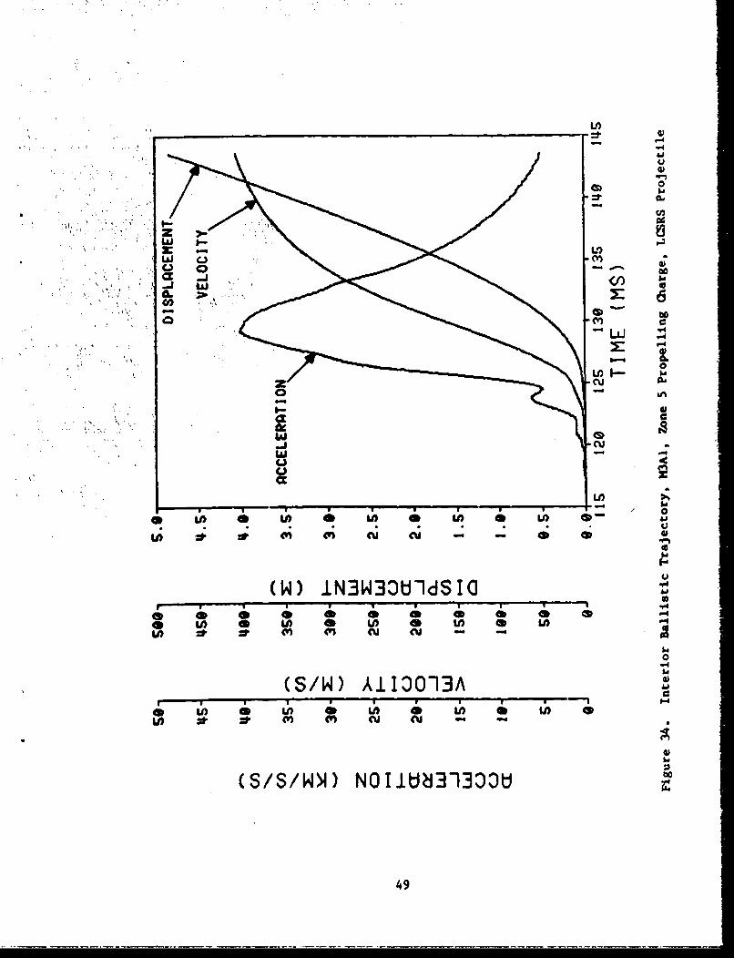
34 Interior Ballistic Trajectory, M3A1, Zone 5 PropellingCharge, LCSRS Projectile ..... ............................. . 49
35 Interior Ballistic Trajectory, M4A2, Zone 7 PropellingCharge, LCSRS Projectile ..................................... 50
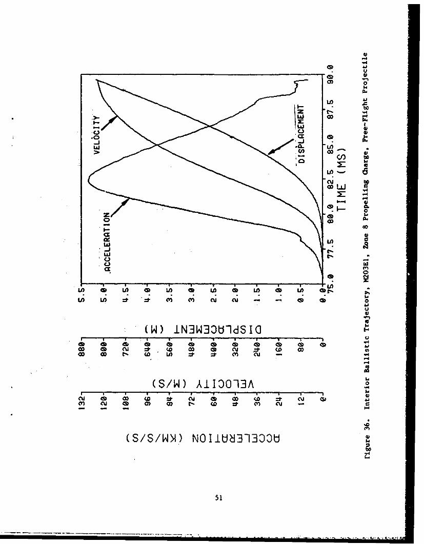
36 Interior Ballistic Trajectory, M203EI, Zone 8 PropellingCharge, Free-Flight Projectile ..... ...........0 0 . 51
37 Pressure versus Time, M3AI, Zone I Propelling Charge,LCSRS Projectile .................. ........... .......... ...... * ..* * 52
38 Pressure versus Time, tl3AI, Zone 3 Propelling Charge,LCSRS Projectile ... ........ *.... *..... .... *6..00 .... .... 53
39 Pressure versus Time, M3AI, Zone 5 Propelling Charge,LCSRS Projectile *..*....*.........*...... **..... ..... *... ... 54
40 Pressure versus Time, M4A2, Zone 7 Propelling Charge,LCSRS Projectile ...... . ........................... ..... 55
6

LIST OF ILLUSTRATIONS (CONT'D)
Figure Page
41 Pressure versus Time, M203EI, Zone 8 Propelling Charge,Free-Flight Projectile ................... ................. 56
42 Base Pressure, Acceleration, Resistive Pressure versus Time,M3A1, Zone 1 Propelling Charge, LCSRS Projectile .............. 58
43 Base Pressure, Acceleration, Resistive Pressure versus Time,H3Al, Zone 3 Propelling Charge, LCSRS Projectile .............. 59
44 Base Pressure, Acceleration, Resistive Pressure versus Time,M3AI, Zone 5 Propelling Charge, LCSRS Projectile.............. 60
45 Base Pressure, Acceleration, Resistive Pressure versue Time,M4A2, Zone 7 Propelling Charge, LCSRS Projectile .............. 61
46 Base Pressure, Acceleration, Resistive Pressure versus Time,M203EI, Zone 8 Propelling Charge, Free-Flight Projectile...... 62
47 Resistive Pressure versus Displacement, M3WJ, Zone 1Propelling Charge, LCSRS Projectile .......................... 63
48 Resistive Pressure versus Displacement, K3A1, Zone 3Propelling Charge, LSCRS Projectile....*...................... 64
49 Resistive Pressure versus Displacement, K3AL, Zone 5
50 Resistive Pressure versus Displacement, M4A.2, Zone 7Propelling Charge, LCSRS Projectile .......................... 66
51 Resistive Pressure versus Displacement, M203, Zone 8Propelling Charge, Free-Flight Projectile .................... 67
52 Resultant Cross-Axis Acceleration versus Time, Slotted stickPropelling Charge, Free-Flight Projectile ..................... 70
53 Axial Acceleration versus Time, Slotted StickPropelling Charge, Free-Flight Projectile .................... 71
54 Radial Acceleration versus Time, Slotted StickPropelling Charge, Free-Flight Projectile .................... 72
55 Tangential Acceleration versus Time, Slotted StickPropelling Charge, Free-Flight Projectile .................... 73
56 Axial, Radial, and Tangential Acceleration versus Time,Slotted Stick Propelling Charge, Free-Flight Projectile,Filtered at 2 kHz ............. ........ ..... .. ............ 75
7

LIST OF ILLUSTRATIONIS (ODNT'D)
Figure Page
51 Angular Acceleration versus Time, Slotted Stick Propelling
Charge, Free-Flight Projectile, Filtered at 2 kfHz...........*** 76
58 Angular Acceleration versus Time, Slotted Stick Propelling
Charge, Free-Flight Projectile, Filtered at 3 ki.......77
59 Angular Acceleration versus Time, Slotted Stick PropellingCh(arge, Free-Flight Projectile, Filtered at 4 kHz************* 78
60 Angular Acceleration versus Time, Slotted Stick PropellingCharge. Free-Flight Projectile, Filtered at 5 k~z............. 79
61 Angular Acceleration versus Time, Slotted Granular Propelliniw-Charge, Free-Flight Projectile, Filtered at 5 kiz ............. 80
A
V7-
A%8

I. INTRODUCTION
The continuous measurements of ballistic performance during theinterior ballistic cycle of cannon-launched projectiles is important to on-going research programs being conducted at the Ballistic ResearchLaboratory (BKL). These measurements, such as propelling gas pressure,projectile acceleration, and projectile-bore interactions, are necessary toevaluate existing weapon systems and validate newly formulated interiorballistic models. Of particular interest is the resistance to projectiIemotion and the behavior of the projectile during the engraving process.The measurements of forces on projectiles and projectile-bore interactionsrequire that transducers be located on-board the projectile. In-boremeasufeje~tg gr, r de at BRL using an S-Band telemeter as the datalink.
Standard FM/FM techniques and, when possible, commercially availablecomponents are used. Figure I is a block diagram of a typical transmitting
I11 E.B. Fisher, "Continued Development and Documentation of the Calspan InteriorBallistics Code," ARBRL-CR-00465, Calspan Corporation, Ballistic ResearchLaboratory, USA ARRADCOM, Aberdeen Proving Ground, MD, September 1981.
2 J.W. Evans, "In-Bore Measurements of Projectile Acceleration and BasePressure Using an S-Band Telemetry System," Proceedings of The InternationalTelemetry Conference, Volume XI, October 1975.
3 j.W. Evans, "In-Bore Measurements of Projectile Acceleration and BasePressure Using an S-Band Telemetry System," Proceedings of the Fuze/Munitions Environment Characterization Symposium 11, October 1975.
4j.N. Evans, "In-Bore Measurements of Projectile Acceleration and BasePressure Using an S-Band Telemetry System," Memorandum Report No. 2562,
S.. Ballistic Research Laboratories, Aberdeen Proving Ground, MD, December 1975.
5 J.W. Evans, "Pressure and Acceleration Measurements In Large CaliberCannons," Proceedings of the Tenth Transducer Workshop, June 1979.
j.W. Evans, "Measurements On-Board A Projectile During The In-Tube Travel
"Using An FM/FM Telemeter," Proceedings of DEA-G-1060 Germany-United StatesBallistic Research and Development, October 1980.
7j.W. Evans, "A Technique for Measuring Engraving and Bore Frictional Forcesin Large Caliber Guns," Proceedings of the 1983 JANNAF Propulsion Meeting,CPIA Publication Number 370, February, 1983.
8j.W. Evans, C.R. Ruth, and E.V.Clarke, Jr., "Soft Recovery Tests of A 155-mm
Cr-non Launched Guided Projectile, Type T," ARBRL-MR-03107, BallisticRe. arch Laboratory, USA ARRADCOM, Aberdeen Proving Ground, MD, May 1981.
9

rTRANSDUCERS ANALOG TRANSMITTING SYSTEMSIGNALS
I SIGNAL B-CARRIER_I "C -CONDITIONERJ OSCILLATOR M FREQUENCYPIEZOELECTRIC fI, .L ER 'C 7'U-A.. ®UL'L
,,.--CONDITIONER OSCiLLATOR TRANSMITTERIRESISTIVE I I q" fI+ f 2÷..K• SIGNAL ] - SUB"- CARRIER"
I CONDITIONER OSCILLATOR fNIT-HERMOCOUPLE
""401 f"-EJ-AN-ALOP-<I166~DATA I
I FILTER II RECEIVER VD BAND PASS DISCRIMINATOR DATA ., I
'FILTER f2 FIERf B I
,,I,rIBANO PASS fNI-tLOSCR'DATOAIL RECEIVING SYSTEM F-E N
Figure 1. Standard FM/FM Telemetry System
and receiving system.9 The transmitting system is on the projectile. Thetransducers and the associated signal conditioning frequency modulate thesubcarrier oscillators. The subcarrier frequencies are summed and modulatethe transmitter to form the FM/FM system. The real time data aretransmitted, via the radio frequency link, to the receiving antenna. Thereceiver detects and discriminates the RF signal and outputs the videosignal that is fed to parallel band-pass filters. This video signal is thesame as the frequency multiplexed signal that originates from tne sub-carrier oscillators of the transmitting system. The band-pass filtersselect the desired subcarrier and present IL to the discriminator used inthe second detection process. The voltage analog signals for the variousdata channels are output through low-pass filters to a recording device.
Standard artillery projectiles are modified and instrumented withtelemetry trdnsmitttng systems. In the past, free-flight projectiles have
9M.H. Nichols and L.L. Rauch, Radio Telemetry 2nd Edition, John Wiley andSons, Inc., New York, NY, 1956.
10
'rmr WP-r'*r¶ P~ .A~ rJ*

been test fired and data successfully extracted via the real-time telemetrydata link. The construction of telemetry transmitting systems is expensiveand time-consuming. Therefore, it is desirable to recover the projectileso the instrumentation package can be reused. It is also desirable torecover the instrumentation so the transducers and transmitting system canbe recalibrated after they have been exposed to the launch environment.With the design and construction of the BRL Large Caliber Soft RecoverySystem (LCSRS), 1 0 11 12 a useful tesh fparatus is available that permitsreusing the instrumentation package. Therefsie, artillery projectilesare modified for use with the LCSRS and instrumented with a telemetry
. transmitting system. They have been test fired, recovered, and theinstrumentation reused on subsequent rounds.
This report discusses the technique used to acquire the on-board data.*It includes a description of the telemeiry transmitting system, thetelemetry receiving system, calibrstion procedures, and projectilemodifications. Representative data acquired from test firings arepresented from a number of instrumented projectiles fired both free-flightand into the LCSRS.
IL. TELEMETRY TRANSMITTING SYSTEM
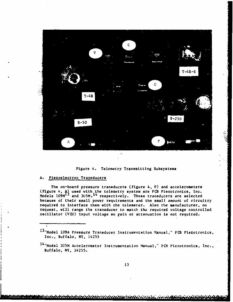
A block diagram of a typical telemetry transmitting system is shown asFigure 2. This four channel system is configured to measure pressure and-acceleration using piezoelectric transducers. Although only four channelsare shown, several additional channe.'s can be added as required. Thesubsystems used are commercially ava. lable and can be configured to makethe desired measurement. Hardware for a 155-un, 4101 free flightprojectile are shown as Figure 3. This system consists of a batterypack(B), the transmitter/antenna module(T), the electroniicx module(E), theacceleremeter(A), and the pressure transducer(P). Also shown is thecompletely packaged transmitting system in a fuze hoising. Each module isencapsulated in an epoxy and all the voids within the, fuze housing are alsofilled. The individual subsystems, before interconnecting and packagingare shown as Figure 4.
10 E.J. Halcin and J.A. Pratt, "Design of A Large Caliber Soft Recovery Systemfor the Ballistic Research Laboratories," Contract Report No. 308, Honeywellinc., Ballistic Research Laboratories, Aberdeen Proving Ground, MI, August1976. (AD #BO13626L)
11J.W. Evans, E.V. Clarke, Jr., and C.R. Ruth, "Large Caliber Projectile SoftRecovery," Proceedings of the 1979 JANNAF Propulsion Meeting, CPIAPublication Number 300, Volume 1, March 1979.
12 E.V. Clarke, Jr., C.R. Ruth, J.W. Evans, J.E. Bowen, J.R. Hewitt, and J.L.Stabile, "Large Caliber Projectile Soft Recovery," ARBRL-MR-03083, BallisticResearch Laboratory, USA ARRADCOM, Aberdeen Proving Ground, MD, February1981.
11

IMPEDANCE C
CONVERTER.0
I CONVERTER
I CONVERTERI p MT
CURRRENG 2.2 G
CdCEL
IMPEDANCER
Fiue'CeeetYCmoet
CONVER~ER l 12
C!
B-50
Figure 4. Telemetry Transmitting Subsystems
A. Piezoelectroc Tranmducers
The on-board pressure transducers (Figure 4, P) and accelerometers(Figure 4, t used withthe telemetry system are PCB Piezotronics, Inc*Models 10914 and 305M, respectively. These transducers are selectedbecause of their small power requirements and the small amount of circuitryrequired to interface them with the telemeter. Also the manufacturer, onrequest, will range the transducer to match th, required voltage controlledoscillator (VOO) input voltage so gain or attenuation is not required.
1 3 "Model 109A Pressure Transducer Instrumentation Manual," PCB Piezotronics,Inc., Buffalo, NY, 14255
1 4 "Model 305M Accelerometer Instrumentation Manual," PCB Piezotronics, Inc.,Buffalo, NY, 14255.
13
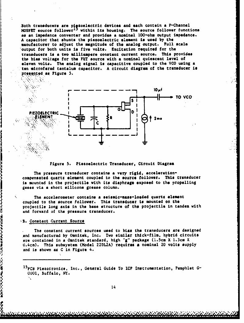
Both transducers are ptl toelectric devices and each contain a P-ChannelMOSFET source follower within its housing. The source follower functionsas an impedance converter and provides a nominal 100-ohm output impedance.A capacitor that *hunts the piezoelectric element Is used by themanufacturer to adjust the magnitude of the analog output. Full scale
output for both units is five volts. Excitation required for thetransducers Is a two milliampere constant current source. This providesthe bias voltage for the FET source with a nominal quiescent level ofeleven volts. The analog signal is capacitive coupled to the VCO usingaton microfarad tantalum capacitor. A circuit diagram of the transducer is
pr~e~ztedasFigure 5.
IPIEZOILeCTRIC IG----LýMENT
Figure 5. Piezoelectric Transducer, Circuit Diagram
The pressure transducer contains a very rigid, acceleration-compensated quartz element coupled to the source follower. This transduceris mounted in the projectile with its diaphragm exposed to the propellinggases via a short silicone grease column.
The accelerometer contains a seismic-mass-loaded quartz elementcoupled to the source follower. This transducer ts mounted on the
p rojectile long axis in the base structure of the projectile In tandem withand forward of the pressure transducer.
13. Constant Current Source
The constant current sources used to bias the transducers are designedand manufactured by Omnitek, Inc. Two similar thick-film, hybrid circuitsare contained In a Omnitek standard, high "Sg package (1.5cm X 1.3cm X0.4cm). This subsystem (Model 22DL2A) requires a nominal 20 volts supplyand is shown as C in Figure 4.
4 ~ 5PCD Fiezotronics, Inc., General Guide To ICP Instrumentation, Pamphlet G-0001, Buffalo, NY.
14
C. Analog Amplifier
In the event that a transducer analog output voltage does not matchthe VCO requirements, an amplifier (Figure 2, Channel #2) is used toprovide the necessary gain. The amplifiers used are Omnitek, Inc. Model23L5-YE. These are differential amplifiers, here used in the single-endedmode, that have a variable gain, up to 500, contolled by an externalresistor. They are thick-film, hybrid circuits packaged in a k.icm X1.3cm X 0.8cm high "g" package (Figure 4, G).
D. Voltage Controlled Oscillator
The Omnitek, Inc. VCOs used have center frequencies that are separatedby 64 kHz starting at 128 kHz. Each has a frequency deviation of + 16 klizthat is a function of the input voltage. The input voltage range Totypically zero to five volts or + 2.5 volts, but can be tailored by themanufacturer to meet a specific requireament. The VCOs (Model 21CI-WEY)require a 20 volt power supply and are packaged in the standard high "g"package. The output of the VCOs have sufficient isolation so several canbe connected together on a common bus. The VCO output amplitude isadjusted by an external resistor to provide the required modulation signalto the transmitter.
When a greater data frequency response is required, VCOs with agreater frequency deviation are used. Similar VCOs with a frequencydeviation of + 32 kkz are available. These units have center frequenciesseparated by T28 kHz starting at 384 kHz. VCOs with the two differentfrequency deviations may be used on the same transmitting system providedthe required guard bands are not violated.
E. Limiter Circuit
In some cases it is desirable to modulate two VCOs, with differentinput voltage ranges, with the same transducer. This provides a high andlow resolution channels. During the event, the high resolution channel isoverdriven. The limiter circuit is used to insure that the VCO does notoscillate outside its prescribed frequency band and interfere with anotherdata channel. The limiter circuit senses the VCO input voltage and when itexceeds the maximum permitted, it short circuits the VCO amplitude adjustresistor. This inhibits the VCO output and essentially turns off that datachannel. The limiter circuit (Models 22DLI & 22DL2) are designed andmanufactured by Omnitek, Inc. Two separate circuits are contained in thestandard, high "g" package.
F. Mixer Amplifier
In the event that the VCOs do not have sufficient output amplitude todirectly drive the transmitter modulation, a mixer amplifier is used. Theoutput of several VCOs can be connected to a common bus and to the input ofthe mixer amplifier. These amplifiers (Model 22MIA-E, manufactured byOmnitek, Inc.) have a fixed gain of 20 and are packaged in the standard,High "g" package.
15

G. Transmitter
The transmitters are manufactured by Hicrocom Corporation and have anominal frequency of 2.22 GRz and output power of 20 millivatte. Twomodels (Figure 4) are used. The Hodel T-4B-S has a semi-rigid coaxialcable for its RF output port while the Model TOR has a push connectorconcentric wi.th the transmitter case. The selection of which type to useis determined by the antenna configuration. This basic transmitter Is afree-running oscillator that has the capacity of 150 milliwatta output, butan attenuator is incorporated within its case to provide isolation betweenthe transmitter and the antenna. This is done to minimise the frequencyshift due to the varying voltage-standing-wave ratio as the projectiletravels in the Sun tube. The transmitter requires a 20-volt power supplyat 50 milliamperes and has a nominal modulation sensitivity of 0.7volts/MHz. The transmitters are frequency modulated by the frequencymultiplexed signals from the VCOs. The amplitude of the individual VCOoutputs are adjusted for the required peak carrier deviation.
Since data is acquired during the interior ballistic cycle, it isnecessary to select a transmitter frequency that will propagate while inthe Sun tube, which Is emsentially a circular wave guide. From the theoryof circular wave guides, 1 6 the cutoff frequency of the gun tube isdetermined by the relationship:
f - cp/wd (1)
where: f - cut-off frequencyc a speed of lightp - constant (1.84 for dominate
mode propagation)d a diameter of the gun tube
Any frequency below cutoff results in complete attenuation while in thetube and any frequency above cutoff will propagate. The 2.22 GRstransmitter selected will propagate from an SO--m tube.
H. Antennas
The antennas used on the free-flight rounds are formed by a slotmilled in a brass cylinder (Figure 3) that Is attached to the front of thefuse housing. This configuration is selected since it presented a flatsurface, on front of the projectile, to a microwave doppler radar that isused for independent projectile displacement measurements. The 1.6-m-wideslot is a segment of a circle with an arc radius of 27.6 mm and a chord of53.5 sm. The slot is filled with a fiberglass sheet that provides the
16L.A. Ware and H.R. Reed, Communication Circuits, 3rd Ed., John Wiley andSons, Inc., New York, NY, 1958
16
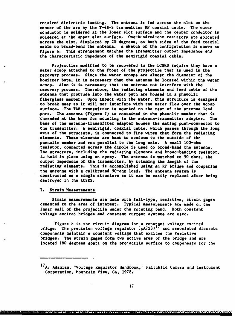
required dielectric loading. The antenna is fed across the slot on thecenter of the arc by the T-4B-S transmitter RF coaxial cable. The outerconductor is soldered at the lower slot surface and the center conductor issoldered at the upper slot surface. One-hundred-ohm resistors are solderedacross the slot, displaced by 20 degrees, on both sides of the feed coaxialcable to broad-band the antenna. A sketch of the configuration is shown asFigure 6. This arrangement matches the transmitter output impedance andthe characteristic impedance of the semirigid coaxial cable.
Projectiles modified to be recovered in the LCSRS rnquire they have awater scoop attached to the front of the projectile that is used in therecovery process. Since the water scoops are almost the diameter of thehowitzer bore, it is necessary that the antenna be located within the waterscoop. Also it is necessary that the antenna not interfere with therecovery process. Therefore, the radiating elements and feed cable of theantenna that protrude into the water path are housed in a phenolicfiberglass member. Upon impact with the water, this structure is designedto break away so it will not interfere with the water flow over the scoopsurface. The T4S transmitter is mounted to the rear of the antenna leadport. The antenna (Figure 7) is contained in the phenolic member that isthreaded at the base for mounting in the antenna-transmitter adapter. Thebase of the antenna-transmitter adapter houses the mating push-connector tothe transmitter. A semirigid, coaxial cable, which passes through the longaxis of the structure, is connected to fine wires that form the radiatingelements. These elements are bent to conform to the outside of thephenolic member and run parallel to the long axis. A small 100-ohmresistor, connected across the dipole is used to broad-band the antenna.The structure, including the radiating elements and broad-banding resistor,is held in place using an epoxy. The antenna is matched to 50 ohms, theoutput impedance of the transmitter, by trimming the length of theradiating elements. This is accomplished using an RF bridge and comparingthe antenna with a calibrated 50-ohm load. The antenna system isconstructed as a single structure so it can be easily replaced after beingdestroyed in the LCSRS.
I. Strain Measurements
Strain measurements are made with foil-type, resistive, strain gagescemented to the area of interest. Typical measurements are made on theinner wall of the projectile under the rotating band. Both constantvoltage excited bridges and constant current system are used.
Figure 8 is the circuit diagram for a cons;4nt voltage excitedbridge. The precision voltage regulator (uA723)11 and associated discretecomponents maintain a constant voltage that excites the resistivebridges. The strain gages form two active arms of the bridge and arelocated 180 degrees apart on the projectile surface to compensate for the
17A. Adamian, "Voltage Regulator Handbook," Fairchild Camera and InstrumentCorporation, Mountain View, CA, 1978.
17
BROADIIANDI NG -
$OLDR 3.5mm------ ýýRESISTORS
fl-mmLASS
XMTR HOUSING& ADAPTER TOFUZE HOUSING
ZCOSAXIAL CABLETO XMTR
Figure 6. Slot Antenna
-SROAD&ANDING
RADIATING
-*, -PHENOL IC
* SEMI-RIGIDCOAXIAL
CONNECTOR*.Scm .
ANTE NNA-XMTRI ADAPTER
PUSHCONNECTOR
TO XMTRFigure 7. Dipole Antenna
18
wi cWN lu

B+
1723I
7K.7- ALL STRAIN GAGESR.-350a
Figure 8. Strain Measuring System, Constant Voltage
bending moment of the projectile. The inactive arms of, the bridge consistsof similar strain gages isolated from mechanical strain. The use of thesame type of bridge components minimize thez-oal drift. The differential,analog voltage output is amplified by an Omnitek amplifier to make itcompatible with the VOes.
The constant current system (Figure 9) uses an Omnitek constantcurrent circuit. The gage is connected to one current source and thenoniinverting input of an Omnitek amplifier. A resistor conuected to theother current source and the inverting input of the amplifier is used toadjust the quiescent output of the amplifier. This circuit is used whenthermal drift is not critical since the gage and resistor have differenttemperature coefficients. The gain of the amplifier is adjusted to make thesystem compatible with the VCO.
J. Power Supply
The power supply for the transmitting system is configured using B-250or B-50 nickel-cadmium cells. The B-250 cells have a current rating of 250milliampere-hours and the B-50 have a 50 milliampere-hour rate, both at a10-hour rate. The cells are connected together, by spot welded metal tabs,and encapsulated in an epoxy. Eighteen series connected B-250 cellsprovide a typical transmitting system with a 22-19 volt supply for greaterthan one hour. The 8-50 cells are used when space restricts the use of thelarger B-250 cells. Two paralleled stacks are required for operating thetransmitting system for about one-half hour. These relative long operatingperiods permit system check-out and calibration using battery power.
19
~~~~~~~. J. le e -• • • •

S- -=" - -- =DUAL~CONSTANTI÷" l ICURRENT
SOURCEL.___ _ MODULE
TOSTRAIN qV.C.O.GAGE b IALANCE
L RESISTOR
Figure 9. Strain Measuring System, Constant OQrrent
This type power supply is selected since the nickel-cadmium cells canbe recharged up to 1000 times. Recharging requires 140% of themilliampere-hours drained. The recharging constant current is 25 and 5milliamperes for the B-250 and B-50 respectively.
The positive side of the battery pack is hard wired to thetzar.s, itting system and also to a test Jack for monitoring and charging.The negative side is wired to a floating test Jack. Since the common nodesof the transmitting subsystems are common to the projectile body, thebattery negative test Jack is shorted to the projectile body to turn thesystem on. A sketch of the shorting bar is presented as Figure 10.
\ PROJECTILE
SCREWDRIVER W O TSLOT .-- "WIRE TO SATTERNY
SLOT .. MINUS TERMINAL
SHORTING$AR
INSULATE\D
TEST JACK
Figure 10. Shorting Bar
11. TELEMETKY RECEIVING SYSTEH
A block diagram of the telemetry receiving system is presented asFigure 11. Six data channels are shown, but only those applicable to aparticular round are recorded. Additional channels are added if required.
20
Ir
PM DC VIDEO CAL ON CAL OFF0,TPUT QQ
Is kHzLOW PASS
FILTERFM VIDEO OUTPUT I
AICRMNATYZR
19 21tH
~ . .. . .. .. . .. .. .. . .. ,, , W t A t,*,,J08 ,A~2

A. Radio Frequency Receiving System
The output signals transmitted from the projectile during the in-tubetravel are received via a helical antenna (Andrew Corp., Model 55305)located forward and to the side of the muzzle. It was determined thatprecise positioning of the antenna is not critical, except that it beplaced outside the area of extreme muzzle blast to prevent damage. Outputsignals from the antenna are fed into a down converter (NU-DEL Electronics,Model #MDC2223) that translates the nominal 2.22 GHz signal to a nominal235 M0z signal. This is done to avoid the large attenuation at the 2.22GHz frequency caused by the 30 metres of coaxial cable (RG-8/U) between theantenna and the receiver. Signal level input to the Astro Communicationsreceiver (Model #TR1O4/Model THIOOP Tuning Head) is then at minus 40 dbm.For most programs, the receiver intermediate frequency (IF) bandwidth is3.3 MHz and the video bandwidth is 750 kHz. An output from the tuning headis fed to a spectrum display unit (Astro Communications, Model #103&P) andthe video is fed to a Nelson Ross spectrum analyzer (Model # TAI013) aswell as the bank of subcarrier discriminators. The spectra are used as anindicator while monitoring, adjusting, and calibrating the telemetrytransmitting system.
The frequency modulated, direct coupled, video output signal of thereceiver is used as an indicator of the transmitter frequency stabilityduring the interior ballistic cycle. This signal is amplified and passedthrough an 18 kHz low pass filter to eliminate the subcarrier frequencies.This incidental FM is used to determine if the RF signal stayed within theIF bandwidth.
B. Data Discriminating System
The data discriminators used in the second detection process are EMRData Systems Model #4130. Each discriminator assembly contains a channelselector module that has an input band width of 32 kIz and a centerfrequency that corresponds to one of the transmitting systemssubcarriers. Also each discriminator assembly contains a low-pass, outputfilter module with a bandwidth of 8 kHz through which the analog datapasses. Six discriminators are contained within a single chassis alongwith a calibration module. The video output from the receiver is fed tothe channel selector modules via a common bus. The output from eachdiscriminator channel is interrupted 350 milliseconds prior to the event toinsert a voltage staircase calibration. This complies with an W-housedata format for recording and reducing interior ballistic data.
1 8 C.L. Henry, R.L. Martz, and .. M. Wineholt, "An Improved Procedure For The
Reduction of Interior Ballistic Data Recorded On Analog Tape," MemorandumReport No. 2374, Ballistic Research Laboratories, Aberdeen Proving Ground,MD, April 1974. (AD #919924L)
22
In the event the transmitting system is configured with VCOs withfrequency deviations of + 32 kHz, the channel selector modules must haveinput bandwidths to match. The output filter modules then have bandwidthsof 16 kHz.
IV. TELEMETRY SYSTEM PARAMETERS
The telemetry system is designed to have equal transmission accuracyfor each subcarrier channel. The discriminator output signal-to-noise
,ratio is a function of the varying receiver carrier-to-noise ratio 1as various parameters of the telemetry system. The general formulaused to estimate the noise performance of an FM/FM channel above receiverthreshold is given as follows:
(S/N)d - (SIN)c (3/4) 1I2(Bc/Bs /2( Afc/fs) ( Afs/Bsc) (2)
where:
(S/N)d * Discriminator Output Signal-To-Noise Ratio(RIMS Voltage Ratio)
(S/N)c a Receiver Carrier-To-Noise Ratio
(RMS Voltage Ratio)
Bc - Carrier Bandwidth (Receiver IF Bandwidth)
Bsc - Subcarrier Discriminator Bandwidth
Afc - Carrier Peak Deviation Due To The ParticularSubcarrier Of Interest
fs Subcarrier Center Frequency
Afs Subcarrier Peak Deviations
The receiver carrier-to-noise ratio for FM threshold is four (12 db) andthe minimum acceptable discriminator signal-to-noise is 100 (1% data).
1 9 Telemetry Working Group, Inter-Range Instrumentation Group, Range CommandersCouncil, Telemetry Standards, Document 106-71, White Sands Missile Range, NW88002.
2 OW*J* Cruickshank, "A Feasibility Test of An "S" Band Telemetry System ForMaking In-bore Projectile Measurements," Memorandum Report No. 2335,
Ballistic Research Laboratories, Aberdeen Proving Ground, MD, October 1973.
21W.J. Cruickshank, "Radio Telemetry Formula Applications, A Practical Users
Guide," ARBRL-MR-03364, Ballistic Research Laboratory, Aberdeen ProvingGround, 1D, August 1984.
23
.........................

Other parameters are determined as:
BC = 3.3 MBz (normally used)
Bsc = 8 kHz (for VOW deviation of + 16 kHz)16 kHz (for VWD deviation of _ 32 kHz)
fs VCO Center Frequency
fs - 16 kHz (for VGO deviation of + 16 kHz)- 32 kHz (for VOW deviation of + 32 klz)
The general formula is used to calculate the required carrier peak
deviation due to the various subcarriers. The results of this calculationgives the following relationship:
Af fs af8 -OinU.711 ; for Bae - 8 kHz41
afc rfr i e 1.005 ; for BC 16 ktz
where a is defined as the modulation index. 2 2
Carrier peak deviations are adjusted to the required value by
,adjusting the output amplitude of the VCOs. The magnitude of the variouscarrier deviations are displayed on the video spectrum analyzer whileoperating the entire telemetry system. Relating the displayed magnitudesto the peak deviation requires calibration and adjustment of the receivingsystem. This is accomplished by replacing the telemetry transmittingsystem with an FM signal generator as depicted in Figure 12. Themodulating frequency is varied to determine and adjust the frequency axisof the video spectrum analyzer. The amplitude of the modulating signal isvaried while observing the video and RF spectra. The magnitude of thecarrier and sidebands, displayed on the RF spectrum, vary when theamplitude of the modulating signal is varied. The magnitude of thecarrier, first sidebands, second sidebands, etc., follow the BesselFunctions Jo, J1, J 2 , etc., respectively, with beta as the argument. 2 2 Byselecting a modulating frequency and adjusting the modulating signalamplitude until the magnitude of the carrier or a set of sidebands go tozero, the peak deviation is established. For example, the first carrierdrop-out occurs when a equals 2.405 (first root of Jo). By Increasing themodulating signal amplitude from zero until first carrier drop-out, thepeak carrier deviation can be calculated by 0 U / Is. The gain ofthe receiver video output and/or the gain of the video spectrum analyzercan be adjusted ao desired to display and scale the peak carrierdeviation. The telemetry system can then be observed and adjusted for therequired peak deviation. A sketch of a typical video spectrum is shown as
Figure 13.
22M. Schwartz, "Information Transmission, Modulation, and Noise," 'cGraw-Hill
Book Company, Inc., New York, NY, 1959.
24
FM SIGNAL VARIABLEGENERAOR FREG. OSCI
XMTR DOWNXMTR CONVERTER
RF SPECTRUM "
VCO RECEIVER DISPLAY UNIT
TO DISCRIMINATORS
VCO VIDEOSPECTRUM
ANALYZER
Figure 12. Frequency Modulatiou System, Block Diagram
300
250 I
v IIS
Ir 100zI I
'o IS,50kI I I I
soI ri-" I I I It Ii I I
It',o I I I I I I
Figu e I 1 I I I , IU I I I I II i , I I I I
I I
64 126 192 256 320 384 448SUICARRIER FREQUENCY 1kilz)
Figure 13. Typical Video Spectrum, 83 - 0.711
25
-A ~ A .A ~ ~ IIA A~ A~1 9 9 W V W- -

From FM transm~ission theory,22 a modulation index of 0.711 produces
two significant sidebands (significant sidebands are those with a magnitudeat least one percent of the unmodulated carrier) and a carrier bandwidth(Bc) of four times the frequency ot the modulating signal is recomnended.With the carrier bandwidth normally used, subcarrier channels up to 768 kHzand this modulating index can be used. Should higher frequency channels beused, an adjustment to the normally used 750 kHz video bandwidth must bemade. For the modulatio i index of 1.005, three significant sidebands areproduced and a carrier bandwidth of six times the frequency of themodulating signal is recommended. This permits subcarrier channels up to512 kHz and this modulating index to be used. If higher frequency channelsare required, a wider bandwidth should be used along with the appropriatecarrier peak deviations.
The total carrier peak deviation due to all the subcarriers cannotexceed the transmitter deviation limit or the receiver bandwidth. It isnecessary to observe the data output of the various discriminator channelsto determine distortions and cross-modulation products. In some instancesit is necessary to decrease the carrier deviation using a trial and errormethod to optimize the system.
V. TELEMETRY SYSTEM CALIBRATION
The information transmitted by an FM/FM telemetry system is containedin the frequency of the subcarriers. Therefore, it is necessary to definethe magnitude of the physical quantity being measured in terms of theoutput frequency of the VCOs. It is also necessary to correlate thediscriminated outputs of the receiving system with the subcarrierfrequencies. This, in effect, correlates the discriminated output with thephysical quantities being measured.
A. Piezoelectric Channel Caltbration, Transmitting System
The procedure for calibrating a pressure channel is shown in Figure14. The pressure transdicer is calibrated in a dead weight calibrationfacility. It is subject to several static pressure levels and theresulting output voltage is recorded. The set of points resulting fromthis calibration is used to determine the least square parabola withpressure as the dependent variable and output voltage as the independentvariable. The VCO used in, the pressure channel is calibrated by impressinga series of voltage levels on the input and measuring the resulting outputfrequency. This calibration is made while operating the telemetrytransmitting and receiving systems and counting the output frequency at theappropriate channel selector filter. The measured frequencies arenormalized to a change in frequency (Af) where zero represents the VCOlower band-edge (fa - Afa). The pressure-voltage relationship is used tocalculate a corresponding pressure for the various voltage level inputs tothe VCO. This forms a set of points of pressure and Af that is used todetermine the least square parabola with pressure at the dependent variableand Af as the independent variable. This gives the desired relationshipfor pressure as a function of subcarrier frequency.
26
I ... ,.fr- . . . .. . . ..0. . - . . .

"-•~ a- e n! "b bePRESSURE
TRANSDUCER* CALIBRATION P=
Via f owr.,-
Vi - " "t:
L j
S.. ....m .. n f
VOLTAGECONTROLLEDOSCILLATOR Af , feat -,
CALIBRATIONp ff
P2 Aft
Pe= Afn
Figure 14. Pressure Channel Calibration
The procedure for calibrating an acceleration channel uses themanufacturer's linear calibration factor when an in-house accelerometercalibration facility is not available. The VCD used in the accelerometerdata channel is calibrated and the frequency is normalized in a mannersimilar to the pressure channel (Figure 15). The acceleration-voltagerelationship is used to calculate a corresponding acceleration for thevarious voltage level inputs to the VCO. The resulting set of points areused to determine the least square parabolic fit.
The numerical convolution of the results of the VOW and transducercalibrations is required since it is not practical to make a singlecalibration using the entire telemetry system. This is due to the physicallocations of the two facilities. The form of the output of the convolutedcalibration is required by the in-house data reduction process. The
27
_ -- - - - - - -- - --- - -u --- " b , j j r~LA rý f- P I A l A[ &A.,. A, INA. 4p
AX CA

,-coefficients that are determined are input as the measurand calibrationconstants in the data reduction software.
The output impedance of the piezoelectric transducers is about 100ohms and the input impedance of the VC10s is several hundred kilohus.
S Therefore, the loading factor is negligible and the VCW does notsignificantly alter the transducer output when they are interfaced.Convolution of the transducer calibration and the VOP transfer function istherefore * voJA4 technique.
MANUFACTURER'SN -LINEAR
CALIBRATION
K' V
mmin.. Via oout
L Z_VOLTAG E
CONTROLLEDOSCILLATOR out .be
CALIBRATION J
a32 All,.o
az Af
Ca 9 U +V& W
Figure 15. Acceleration Channel Calibration
B. Strain Channel Calibration, Transmitting System
The strain bridge channels are calibrated end-to-end by substitutingprecision decade resistors for the active arms of the bridge (Figure 16).First, the bridge is balanced with all strain gages connected. Then the
28

active arms are disconnected, one at a time, and the decade resistor isconnected. After each substitution, the bridge is rebalanced to itsoriginal quiescent operating point. When both active arms have beenreplaced, the two substitution resistors are varied by the same resistiveincrements over the expected range. The VC0 frequencies are recorded andnormalized for each increment. The resistive increments are converted tostrain increments using the manufacturer's gage factor. Then the leastsquare parabolic fit is determined for the strain - Af relationship.
C. Receiving System Calibration
The transmitting system calibration is correlated with the receivingsystem via the voltage staircase calibration (Figure 11). The magnitude
fout-
I S$TRAIN CHANNEL IR'CALIBRATION
it f out
* n n
1--"* __
AL/L
A~L/Lo A to
Af¢
~L/L nI
* R -
C AL/L n ab fA
Figure 16. Strain OCannel Calibration
29

and offset of the staircase are adjusted to be compatible with therecording device. The discriminator output voltage is correlated with thecalibration staircase by adjusting its offset and output gain. Thediscriminator chassis contains a calibration module that can produce, usinga crystal oacillator, the center, lower band-edge, and upper band-edgefrequencies of each subcarrier. By manual selection, one calibrationfrequency at a time can be put on the video buss. A block diagram for onechannel (Afs = 16 kHz) is presented as Figure 17. The lower band-edge (fs- Aft) voltage is adjusted to coincide with the staircase baseline and theupper band-edge (fs + Afs) voltage is adjusted to coincide with the
VIDEO FROM RECEIVER
XTAL OSC. TO RECORDER
flib (A f'0) D!SC.
XTAL OWI Ifet (Ais(le)
XTAL 030.VOTG NIO
labs (A f -3CA
UPME IANO 6009 To V
CIDNTER QUNC
LOWEUR WAND SHAKLINKE(A f$\ --SET UP CAUBRATION EVENT
Figure 17. Receiving System Calibration
staircase top calibration step. These two extremes represent 4f equal to
zero and 32 kHz (for Aft - 16 kHz) or 64 kHz (for Afs - 32 kHz)respectively in the transducer - VO0 least square parabolic fit. Thismanual correlation of the staircase to the crystal frequencies is requiredsince an automated calibration system is not available in-house. Therecorded staircase and data from the event represent the VCO frequency-excursion with the staircase steps defining the magnitude of the physicalquantity being measured. The frequency excursion represented by thestaircass top step is input for the system calibration in the datareduction software.
VI. RECORDING AND DATA REDUCTION
The analog data frum the telemetry system, as well as hard-wire data,are recorded In real time by an analog-to-digital converter (A/DC) that is
30

a subsystem of the Ballistic Data Acquisition System (BALDAS). These dataare simultaneously recorded on analog, FII, magnetic tape. Data recorded onanalog tape can be played-back into the BALDAS for digitization. TheBALDAS is a data acquisition and reduction system that operates under thecontrol of a minicomputer (Digital Equipment Corp., PDP-11/45).Peripherals on the system include: magnetic cartridge disk drives, amagnetic tape drive, a printer/plotter (Versatec,lnc.,Model #1100A), aninteractive terminal (Tektronic, Inc. ,Model #4010) as well as theinterfaces that drive the A/DC and other data acquistion hardware. Asimplified block diagram of BALDAS is shown as Figure 18. Analog datadigitized by the A/DC is strobed into the computer memory in real time.The sequence timer, setup under computer control, initiates hardware startssuch as the gun firing pulse. The event timer records the elapsed time forhardware operation and times of arrival such as the firing pulse andvelocit, coil outputs. This is used to coordinate times with the digitizeddata. The analog tape controller automatically operates and monitors theanalog tape recorder during the real time event and during playback of therecorded data into the A/DC. The computer sets up the acquisition hardwarevia the appropriate interfaces and monitors its function as required. Thedata acquisition is accomplished by operator initiation and interaction ofthe range operating personnel.
CENTRAL FLOATINGPROCESSOR POINT MEMORY DIK TAPE TRIA
DIRECT INTERFACEMEMORYACCESS
T ANALOG SEQUENCE EVENTTAPE TIMER TIMER
A/DC CONTROLLER
FI LTERS LAATIMING
ANALOG FUNCTIONSEVENT AND TIMES
TAP OF ARRIVAL SIGNALSRECORDERANALOG
DATA
Figure 18. Ballistic Data Acquisition System, Block Diagram
31
-. d, ,
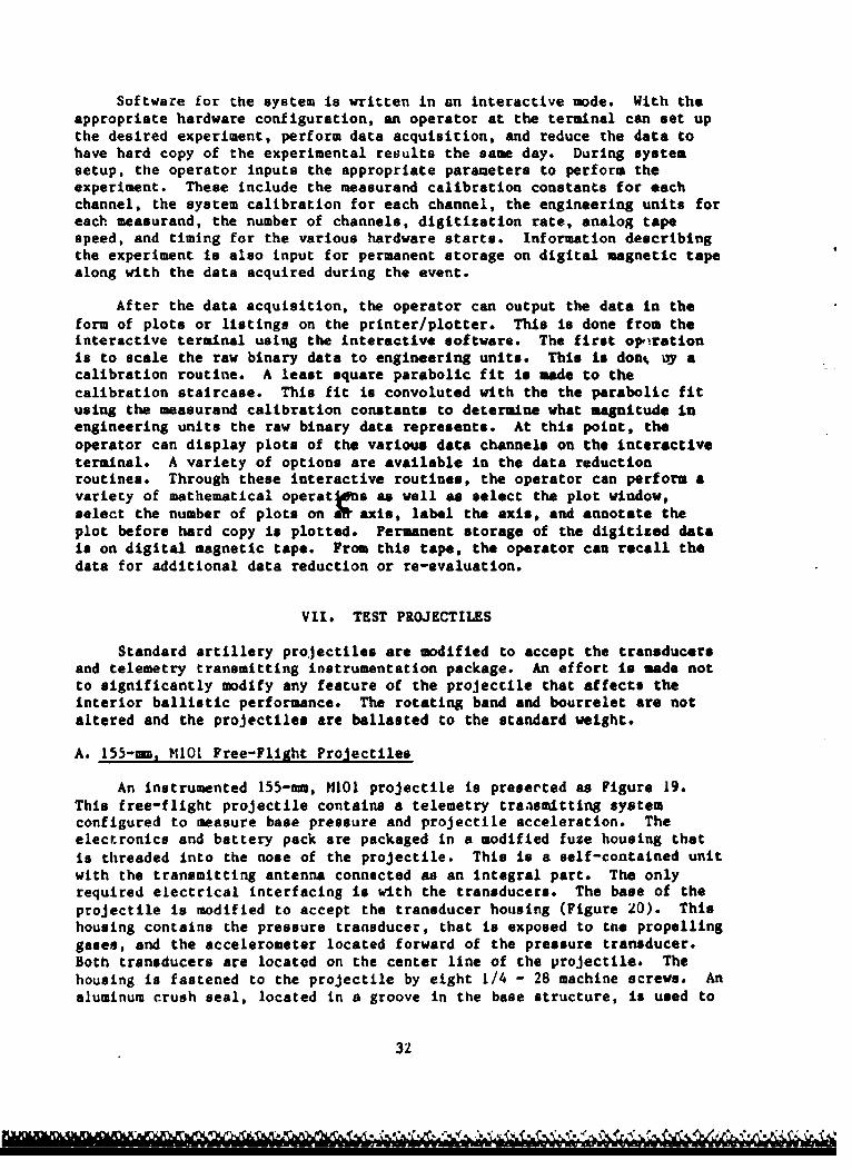
Software for the system is written in an interactive mode. With theappropriate hardware configuration, an operator at the terminal can set upthe desired experiment, perform data acquisition, and reduce the data tohave hard copy of the experimental results the same day. During systemsetup, the operator inputs the appropriate parameters to perform theexperiment. These include the measurand calibration constants for eachchannel, the system calibration for each channel, the engineering units foreach measurand, the number of channels, digitization rate, analog tapespeed, and timing for the various hardware starts. Information describingthe experiment is also input for permanent storage on digital magnetic tapealong with the data acquired during the event.
After the data acquisition, the operator can output the data in theform of plots or listings on the printer/plotter. This is done from theinteractive terminal using the interactive software. The first opirationis to scale the raw binary data to engineering units. This is don% 0y acalibration routine. A least square parabolic fit is made to thecalibration staircase. This fit is convoluted with the the parabolic fitusing the measurand calibration constants to determine what magnitude inengineering units the raw binary data represents. At this point, theoperator can display plots of the various data channels on the interactiveterminal. A variety of options are available in the data reductionroutines. Through these interactive routines, the operator can perform avariety of mathematical operatoens as well as select the plot window,select the number of plots on LW axis, label the axis, and annotate theplot before hard copy is plotted. Permanent storage of the digitized datais on digital magnetic tape. From this tape, the operator can recall thedata for additional data reduction or re-evaluation.
VII. TEST PROJECTILES
Standard artillery projectiles are modified to accept the transducersand telemetry transmitting instrumentation package. An effort is made notto significantly modify any feature of the projectile that affects theinterior ballistic performance. The rotating band and bourrelet are notaltered and the projectiles are ballasted to the standard weight.
A. 155-mm, M1OL Free-Flight Projectiles
An instrumented 155-mm, 1101 projectile is preserted as Figure 19.This free-flight projectile contains a telemetry traasmitting systemconfigured to measure base pressure and projectile acceleration. Theelectronics and battery pack are packaged in a modified fuze housing thatis threaded into the nose of the projectile. This is a self-contained unitwith the transmitting antenna connected as an integral part. The onlyrequired electrical interfacing is with the transducers. The base of theprojectile is modified to accept the transducer housing (Figure 20). Thishousing contains the pressure transducer, that is exposed to tne propellinggases, and the accelerometer located forward of the pressure transducer.Both transducers are located on the center line of the projectile. Thehousing is fastened to the projectile by eight 1/4 - 28 machine screws. Analuminum crush seal, located in a groove in the base structure, is used to
32

ACCELEROMETERPROTECTION CAP INTERFACE TERMINALS BATTERIES
S\ \ TRANSMITTER
ACCELEROMETER ELECTRONIC MODULEPRESSURE GAGE SLOT ANTENNA
Figure 19. Instrumented Free-Flight 155-um, MI01 Projectile
#C T P 0~ct~.w t SSU 6 EIi
Figure 20. 155-t., mio .Projectile Base Modification and TransducerHousing
seal against thie propelliaig gases. After connecting the telemetrytransmitting system to the transducer using stranded, teflon-coated, hook-up wire, the projectile is filled with an epoxy that has the same densityas the high explosive that would normally fill the projectile. This is
33
accomplished through the projectile base and a small hole, tapped for apipe plug, in the side wall of the projectile.
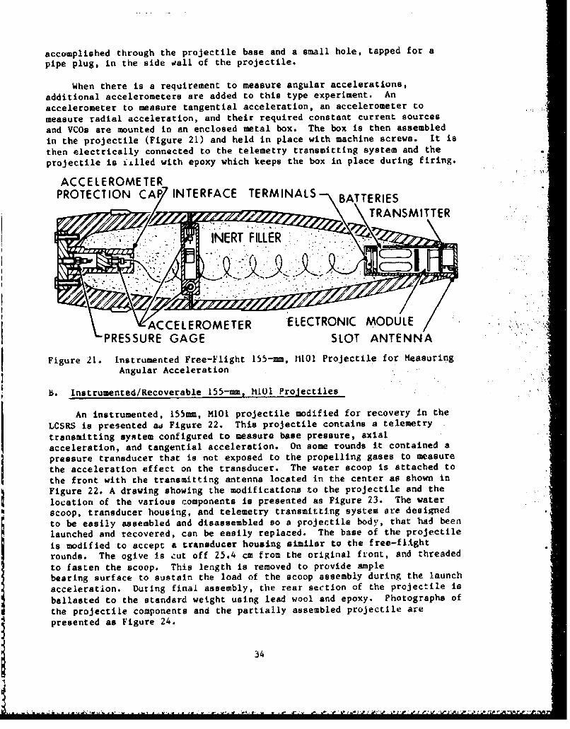
When there is a requirement to measure angular accelerations,additional accelerometers are added to this type experiment. An
accelerometer to measure tangential acceleration, an accelerometer to .. ...
measure radial acceleration, and their required constant current sources
and VCOs are mounted in an enclosed metal box. The box is then assembled
in the projectile (Figure 21) and held in place with machine screws. It is
then electrically connected to the telemetry transmitting system and the
projectile is islled with epoxy which keeps the box in place during firing.
ACCELEROMETERPROTECTION CA7 INTERFACE TERMINALS -\BATTERIES
I •. i::•i". : '- ' INERT FILLER .. :-. .
ACCELEROMETER ELECTRONIC MODULE" , m':
PRESSURE GAGE SLOT ANTENNA
Figure 21. Instrumented Free-Flight 155-mm, 11101 Projectile for MeasuringAngular Acceleration
B. Instrumented/Recoverable 155-mm, MiOl Projectiles
An instrumented, 155mm, MIOI projectile modified for recovery in the
LCSRS is presented aa Figure 22. This projectile contains a telemetry
transmitting system configured to measure base pressure, axialacceleration, and tangential acceleration. On some rounds it contained a
pressure transducer that is not exposed to the propelling gases to measurethe acceleration effect on the transducer. The water scoop is attached to
the front with the transmitting antenna located in the center as shown inFigure 22. A drawing showing the modifications to the projectile and the
location of the various components is presented as Figure 23. The water
scoop, transducer housing, and telemetry transmitting system are designed
to be easily assembled and disassembled so a projectile body, that had been
launched and recovered, can be easily replaced. The base of the projectile
is modified to accept a transducer housing similar to the free-flight
rounds. The ogive is .ut off 25.4 cm from the original front, and threaded
to fasten the scoop. This length is removed to provide amplebearing surface to sustain the load of the scoop assembly during the launch
acceleration. During final assembly, the rear section of the projectile is
ballasted to the standard weight using lead wool and epoxy. Photographs of
the projectile components and the partially assembled projectile arepresented as Figure 24.
34

* Fitgure 2. 1 In trumnte/R coerbl 1..
mmNIIProjectile
"NO4DIFIED 5O n )*11PROJECTILE *\ ELECTRONICS PAODLCOAXICAOL TRANSMITTER
TAAIANTENNA
AccEL ACCE~L EROMETERFigure 23, AXIALACEROTR
35I
TM&

LAI*'.7 t .x.
'r'.*. .1
Figre24.Intruened/ecverbl 15-m, M01Proecil Compnens9
* 36

The transducer housing is fabricated in sections so the transducerscan be changed for subsequent rounds. The rear most section carries thebase pressure transducer, the center section carries a cargo pressuretransducer or an accelerometer, and the forward section carries the jacksof a two-conductor, coaxial connector for interfacing with the telemetryelectronics. Interconnections within the transducer housing are made usingteflon-coated wire through the wiring channels on the sides. After theconnections are made, the wiring channels are filled with a rubberencapsulant (Dow Corning, 3120 RTV) and the transducer housing is coveredwith shrinkable tubing.
The scoop assembly is fastened together using four threaded studs.The battery housing carries the transmitter and eighteen B-250 cells forthe power supply. This module also contains the test jacks for batterycharging and system turn-on. All other electronic modules are contained inthe telemetry carrier along with an axial accelerometer and a tangentialaccelerometer. The telemetry carrier also carries the plugs of the two-conductor, coaxial connector. The electronic modules are interconnectedand cast in an epoxy.
After a structure failure, the projectile system was redesigned toeliminate weight from the scoop assembly. The battery housing wasredesigned to carry B-50 cells for the power supply. The telemetryelectronics were moved to the transducer housing by adding a section. Thetangential accelerometers were attached to the wall of the projectile andwere encapsulated by the epoxy used for ballast. A drawing of theredesigned projectile, showing the location of the various components, ispresented as Figure 25.
MODIFIED 155-mm,MIOI PROJECTILE ANSMITTER
• COAXIAL •-ANTENNACONNECTORS WATER
ACCELEROMETER ANGENTIAL ACCELEROMETER
-PRESSURE ELECTRONICS MODULESTRANSDUCER
Figure 25. Redesigned 155-mm, M101 Recoverable Projectile
37
IVA~~~ ~ ~ ~ ~ %* 00V**- -1 V N.No'0-
VIII. FIRING PROGRAMS
All firing programs are conducted at the Interior Ballistic Division,
BRL Sandy Point Facility (Range 18). The data are received, recorded, and
reduced using the on-site BALDAS system.
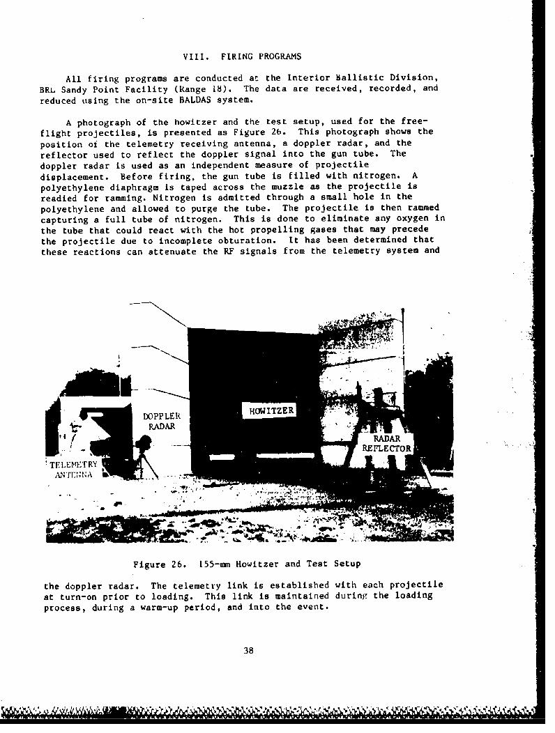
A photograph of the howitzer and the test setup, used for the free-
flight projectiles, is presented as Figure 26. This photograph shows the
position of the telemetry receiving antenna, a doppler radar, and the
reflector used to reflect the doppler signal into the gun tube. The
doppler radar is used as an independent measure of projectile
displacement. Before firing, the gun tube is filled with nitrogen. A
polyethylene diaphragm is taped across the muzzle as the projectile is
readied for ramming. Nitrogen is admitted through a small hole in the
polyethylene and allowed to purge the tube. The projectile is then rammed
capturing a full tube of nitrogen. This is done to eliminate any oxygen in
the tube that could react with the hot propelling gases that may precede
the projectile due to incomplete obturation. It has been determined that
these reactions can attenuate the RF signals from the telemetry system and
• i m q HOW•ITZ R.DOPPLER
RADAR S. ... • REFLECTOR" ""
TELEMTRY
, in
Figure 26. 155-mm Howitzer and Test Setup
the doppler radar. The telemetry link is established with each projectile
at turn-on prior to loading. This link is maintained during the loading
process, during a warm-up period, and into the event.
38

A. Free-Flight Projectiles
Five projectiles, of the type shown in Figure 19, were fired from a155-mm, M185 special howitzer tube using M203E!, Zone 8 propelling charges.The first two projectiles fired did not have the &..celerometer protectioncap (Figure 19). This caused distortion of the acceleration data due tothe mechanical loading of the accelerometer st:ucture by the inert fill.The pressure data were received during the entire in-tube travel. Theaddition of the cap'for subsequent rounds solved the mechanical loadingproblem. Of the other projectiles fired, two lost signals near peakpressure. It is suspected that this was caused by an open circuit in thebattery pack. The other projectile transmitted 6ata during the entireinterior ballistic cycle.
Four projectiles, of the 'ype shown in Figure 21, were fired from a155-mn, H199 howitzer rube using experimental charges that hid chamberpressure magnitudes near that of a Zone b. Two of these rounds tranGmittedduring the entire interior ballistic trajectory, one lost transmission justafter peak pressure, and one had a 5 millisecond drop-out during peakpressure.
Unfortunately, the free-flight rounds impacted in the water and werenot recoverable. Therefore, the failure modes that existed could not bedetermined.
- B. Soft Recovery of Instrumented Projectilel
The construction of a telemetry transmitting system is expensive.Therefore, it is desirable to recover the projectile so the instrumentationpackage can be reused. It is also desirable to recover the instrumentationso the transducers and transmitting system can be re-calibr ted after beingexposed to the launch environment. At the BRL, a LCSRSI 0 I is inoperation.
A schematic showing the LCSRS principle of operation is presented asFigure 27. Soft recovery of the projectile is achieved by attachiTg awater scoop to the test projectile and firing it into a water trouga,inclined at a small angle to present an ever-increnaing depth of watir tothe advancing projectile. The momentum of the projectile is transfeired tothe water ejected forward by the scoop. The water scoop is designed Lo
have the necessary interior contour to eject the impacted water forward.The water enters onto a conical surface of revolution thnt transitions intoa spherical surface of revolution.
The LCSRS apparatus is presented as Figure 28. The projectile islaunched through a band cutter, attached to the muzzle, that removes the
protruding portion of the rotating band. This 3llows che tolerance betweentht projectile body and the LCSRS to be much tighter than if the rotatingband were left on. This prevents the rotating band from acting as afulcrum, thus minimizing balloting during recovery. After passing through
39

WATER SCOOP TOP RETAINING RAIL
TROUGH ANLWATE--• WATER AREA
PROJECTILE BODY-
Figure 27. Large Caliber Soft Recovery System, Principle of Operation
,%. *, .'.
Figure 28. Large Caliber Soft Recovery System
the band cutter, the projectile passes through an entrance cone assemblyand into the reccvery system proper, which consists of the bottom watertrough and the overhead, inverted retaining crane rail. The whole assemblyis angled slightly by means of five pairs of Jacks that cause thepprojectile to be exposed to the increasing depth of water. The terminalend of the LCSRS is equipped with a specially designed shock absorber toabsorb any residual momentum when the projectile has traveled the entirelength of the system. The 60-metre length of the system is sufficient tostop the projectile with a maximum deceleration of less than ten percent ofthe maximum launch acceleration.
40
C. Recoverable Projectiles
The projectile system, as configured in Figure 23, was fired from an155-tm, M185 howitzer on five occasions, changing t ie projectile body aftereach round. Since different zone propelling charges were used, thetransducers were changed as required so a transducer with the range of thepredicted measurand magnitudes was used. The propelling charges used wereK13Al, Zones 1, 3, and 5 and M4A2, Zone 7. Removing the water scoopassembly required machining of the projectile since the torque experiencedduring launch tightened the threads. The fifth round was indexed on theprojectile body and the scoop to determine their relative angulardisplacement during launch and recovery. The threads on this roundtightened by 24 degrees, corresponding to an 0.21-in linear distance,causing an interference fit. It was determined on subsequent rounds thateliminating the antiseize lubricant (Ul-Temp, CS-A), used on the threadsduring assembly, permitted scoop removal without machining.
The telemetry link, with each of the projectiles, was maintainedduring the entire interior ballistic cycle for all rounds except the fifth.This round lost signal at about one millisecond past maximum pressure.After recovery, each projectile was refitted with a new antenna and thesystem was turned on and evaluated. All measurable parameters (VCOfrequencies, transmitter frequency, battery voltage, and transducertquiescent points) on all five rounds were within the pre-launchspecifications except for fifth, that appeared that the constant currentsource to the transducers in the rear section had an open circuit. Thetransmitted base pressure and acceleration data for all rounds appearednormal except for a 1.5 millisecond dropout of the pressure near peak onthe thiru round. This was determined to be caused by a bent Jack on thecoaxial connector that was not properly engaged. The tangentialacceleration data had large ringing due to structural vibration and did notrepresent the tangential acceleration of the projectile, but rather that ofthe scoop because of the relative angular displacement during launch.
The failure on the fifth round was caused by a structural failure inthe projectile system. All four bolts that held the scoop assembly togetherfailed just behind the scoop rear surface. The battery housing and thetelemetry carrier moved to the rear, disconnecting the antenna. Thisaccounted for the signal loss. The coaxial connector was sheared becauseof the motion, causing the electrical connection to the transducers toopen. On recovery, the telemetry carrier and battery housing returned totheir proper position which accounted for the post-launch evaluationresults. After disassembly the telemetry system was reconnected andevaluated. All measurable parameters were then at the pre-launchspecifications.
The redesigned projectile system (Figure 25) was fired on sixoccasions from the M185 howitzer. The propelling churges used were M3AI,Zone 5; M4A2, Zone 7; and M119, Zone 8. The telemetry link for Zones 5 and7 rounds were maintained until the end of the interior ballistic cycle.The transmitted base pressure and axial acceleration data for those roundsappeared normal. The tangential accelaration data showed ringing and on
41
21= 11I I
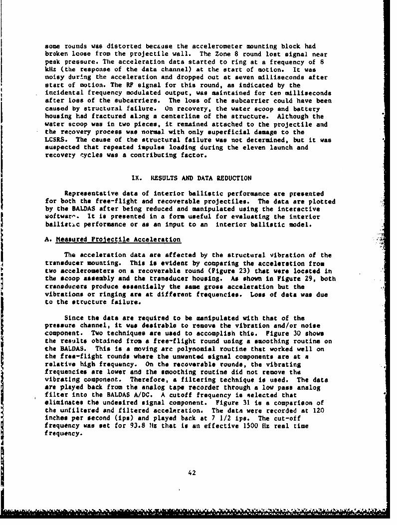
some rounds was distorted because the accelerometer mounting block hadbroken loose from the projectile wall. The Zone 8 round lost signal nearpeak pressure. Ttie acceleration data started to ring at a frequency of 8kHz (the response of the data channel) at the start of motion. It wasnoisy during the acceleration and dropped out at seven milliseconds afterstart of motion. The RF signal for this round, as indicated by theincidental frequency modulated output, was maintained for ten millisecondsafter loss of the subcarriers. The loss of the subcarrier could have beencaused by structural failure. On recovery, the water scoop and batteryhousing had fractured along a centerline of the structure. Although thewater scoop was in two pieces, it remained attached to the projectile and
the recovery process was normal with only superficial damage to theLCSRS. The cause of the structural failure was not determined, but it wassuspected that repeated impulse loading during the eleven launch andrecovery cycles was a contributing factor.
IX. RESULTS AND DATA REDUCTION
Representative data of interior ballistic performance are presentedfor both the free-flight and recoverable projectiles. The data are plottedby the BALDAS after being reduced and manipulated using the interactivevoftwar•. It is presented in a form useful for evaluating the interiorballistic performance or as an input to an interior ballistic model.
A. Measured Projectile Acceleration
The acceleration data are affected by the structural vibration of thetransducer mounting. This is evident by comparing the acceleration from
two accelerometers on a recoverable round (Figure 23) that were located inthe scoop assembly and the transducer housing. As shown in Figure 29, bothcransducers produce essentially the same gross acceleration but thevibrations or ringing are at different frequencies. Loss of data was dueto the structure failure.
Since the data are required to be manipulated with that of thepressure channel, it was desirable to remove the vibration and/or noisecomponent. Two techniques are used to accomplish this. Figure 30 showsthe results obtained from a free-flight round using a smoothing routine onthe BALDAS. This is a moving arc polynomial routine that worked well onthe free-flight rounds where the unwanted signal components are at arelative high frequency. On the recoverable rounds, the vibratingfrequencies are lower and the smoothing routine did not remove the
vibrating component. Therefore, a filtering technique is used. The dataare played back from the analog tape recorder through a low pass analogfilter into the BALDAS A/DC. A cutoff frequency is aelected thateliminates the undesired signal component. Figure 31 is a comparison ofthe unfiltered and filtered acceleration. The data were recorded at 120inches per second (ips) and played back at 7 1/2 ips. The cut-offfrequency was set for 93.8 11z that is an effective 1500 l1z real timefrequency.
42
e Lo L . As

TRANSDUCER IN SCOOP ASSEMBLYes.
90
a.j00
* a°
PP il 2 i3 ill iS iG 47 4 99TIME (F1S)
9 TRANSDUCER IN TRANSDUCER HOU$1NO
-9-
So.
CD,
1- ."0
cr
a: jo
61 i2 63 61 05 96 67 6g 0 1
TIME (MS)
Figure 29. Accolerstion versus Time, H4A2, Zone 7 Propelling Charge,, . LCSRS. Projectile
443

120"
a.
z0
'- 66.
_Jl-J
(-)a
20-
70.0 7.5 75f.0 77.5 so.@ 02. g 0 07.5 sO.#
TIME (MS)
Its.
so.'120
aw
2J
20
0i70.0 72i. 7 7i. 0 77. 00i.0 02.5 S0.0 07.5 00.,
TIME (MS)
Figure 30. Acceleration versus Time, H20391, Zone 8 Propelling CharSe,Free-Flight Projectile
44

N)
C,,
z
a
-J
So.
a
120 335 lie 13514TIME (M1S)
I" 10
Projectile.
045
CA. A, .. 0-.iW wj" K
I0e
iCi
xvi .-. '4
..' , "LiJ:
. i +,
26 325' TIME (MS)}
•-, Ftgure 31. Acceleration vorsue Time, H4A2, Zone 7 Propeling Qiarge, LcSRSProjectile
45

The acceleration data are used to determine the interior ballistictrajectories. The velocity is determined by integrating the accelerationand the displacement is determined by integration of the velocity. Sincethere is not an available in-house calibration facility for accelerometers,the manufacturer's calibration constant can not be verified. When theinterior ballistic trajectories are plotted, the displacements are comparedwith known displacement points acquired from the projectile rotating bandpassage across pressure transducer ports located in the gun tube sidewall. In all cases, the accelerometer acquired displacement data werefound to be lower. It is believed that the pressure port displacements aremore accurate since the pressure port locations are well defined as are thetimes of pressure rise due to band passage. Therefore, the accelerationdata are corrected by mwltiplying by a constant that gives the best fit ofthe displacement curve through the points acquired by the pressure portpassage. The required correction factor varied from transducer totransducer with a range of 1.012 to 1.12. Figures 32 through 36 areinterior ballistic trajectories for rounds fired at various zones, obtainedusing this correction/calibration technique.
B. Measured Base Pressure 4
Pressures measurements from various zone propelling charges arepresented as Figures 37 through 41. The spindle and forward chamberpressures are hard wire data recorded from Kistler, Model 607 pressuretransducers. Since the base pressure data are manipulated with the measuredacceleration, theyr are both smoothed or filtered in a similar manner.Cargo pressure transducers, not exposed to the propelling gases, on severalrounds did not have a significant output caused by the launch accelerationand vibration environment.
C. Resistive Pressure Profile
Applying Newton's Second Law, the axial forces acting on theprojectile are defined by the equation:
PbA - f - ma (3)
where: Pb - Base Pressure
A - Cross-Sectional Area of the Tube
f - Frictional Forces
m - Hass of the Projectile
a - Projectile Acceleration
The frictional forces include the engraving forces of the rotating band,the sliding friction for the projectile/tube, and the pressure buildupahead of the projectile due to the velocity. This force balance equationis rearranged to make each term have units of pressure as follows:
46

0)0
Id
zzow
C.,LC.,
"-4
(W) IN3W30U1dSIO -
cu 0 (1) 0 ('i V0cu - - -
"14
t.1
(S (S/WN) AOIldOO1JA
47
-. ;j-t 0 A- -A- I!

Ul)
U7Ucul
Lh -t -- (n cu v e41
IW) I3W30ldS)
C- LO cu a C- U cu r%- U) c
0)
U) 0 U) 0 U) 0 ~U) 0 ) 0 ) *
484
U)U
LLIIz0
W4
C~
(W) .LN3W33bldSIO;6 40
* ) a~ * A LA LO A6 U
U) S0) ) AII0013A
494

U)U
0
0s'
- 8.
(LC4'
Ul
c-i
La aPcu c
0
(N)/WN LN3WBibdSIO3DDbb
500
-4
0) 016d
w0
.00
'-i
'00.0o
Lj4j
OD LL U
OD0
Ix LfI(S/NO ) LOOM13A 6Li)
MU cu 0 w0 c a cu 0 (0 w U Gco co nl co U - : n c
(S/S/N>4) NOI~d3IJ13ZMU ow
51

do)
41
00U.0.
Laa CD
52.

U)
0)I
(Y..
*n
LO
GCD~Z2Zi
(t~dW) 3vfSS38d.
53
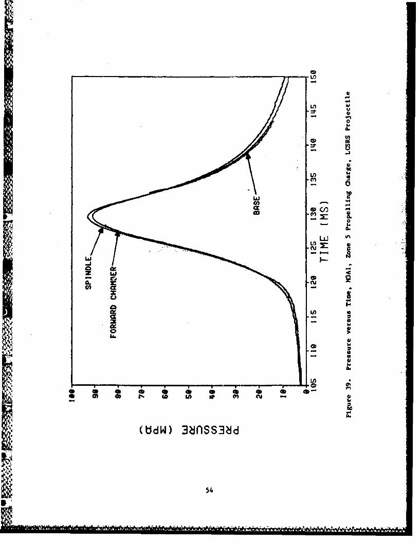
4)
LI)
Cl4)
14~
54~

LA)
i go. -
"€,I.
zS
(::dW) 3nSS38d
55

00 w
(UdW 3eS3I
56.
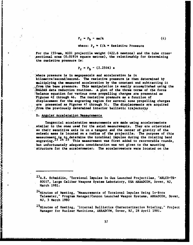
Pr Pb- M/A (4)
where: Pr - f/A - Resistive Pressure
For the 155-mn, MOl projectile weight (422.6 newtons) and the tube cross-,sectional area (0.01914 square metres), the relationship for determiningthe resistive pressure is,
Pr " Pb - (2.2516) a
' *:where pressure is In megapescals and acceleration is inkilometre/second/second. The resistive pressure is then determined bymaltiplying the measured acceleration by the constant and subtracting it
_.erom the base pressure. This manipulation is easily accomplished using the,-3ALDAS data reduction routines. A plot of the three terms of the force•,balance equation for various zone propelling charges are presented asFigures 42 through 46. The resistive predsure as a function ofdisplacement for the engraving region for several zone propelling charges%are presented as Figures 47 through 51. The displacements are acquiredJrom the previously determined interior ballistic trajectqryJ
Do Angular Acceleration Measurements
Tangential acceleration measurements are made using accelerometerssimilar to the ones used for the axial measurements. They are orientatedso their sensitive axis is on a tangent and the center of gravity of theseisaic mas is located on a radius of the projectile. -The purpose of thismoasureuenj 3 4445 determine the torsi6nal impulse during the rotating bandengraving. This measurement was first added to recoverable rounds,but unfortunately adequate consideration was not given to the mountingstructure for the accelerometer. The accelerometers were located on the
2 3 A.E. Schmidlin, "Torsional Impulse In Gun Launched Projectiles, "ABLCD-TR-80037, Large Caliber Weapons System Laboiatory, USA ARRADCOH, Dover, NJ,March 1981.
24Minutes of Meeting, "Measurements of Torsional Impulse Using In-BoreTelemeter," Program Manager/Cannon Launched Weapon Systems, ARRADCOK, Dover,NJ, 5 March 1980
25Minutes of Meeting, "Internal Ballistics Characterization Briefing," ProjectManager for Nuclear Munitions, ARRADrOH, Dover, NJ, 28 April 1981.
57

0))
a
co
a
a sea
04
0A ý -CI
(UdW 4,SSd
541

'U,
* 0
aa
9L aa0:
c wLa.ia
a.(- ad
Ai
"41u4',
cU-
(UdW 38hiýl
59b

LU U
600

V4
L&IV
wO
IL-
Im V4
.41
ws
zz0r "
8Ad
611

0G0))
U))
cU
0o4
Cu6
ww
ad ! 0
0 La w 0)
990
(LaW cclS3i
9L 62
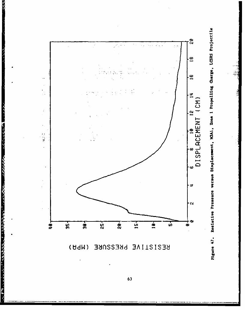
l1CD-c.r4
SLd
41
U.4
- -0"
(UdW)~u 3ds3d3AiITa
633
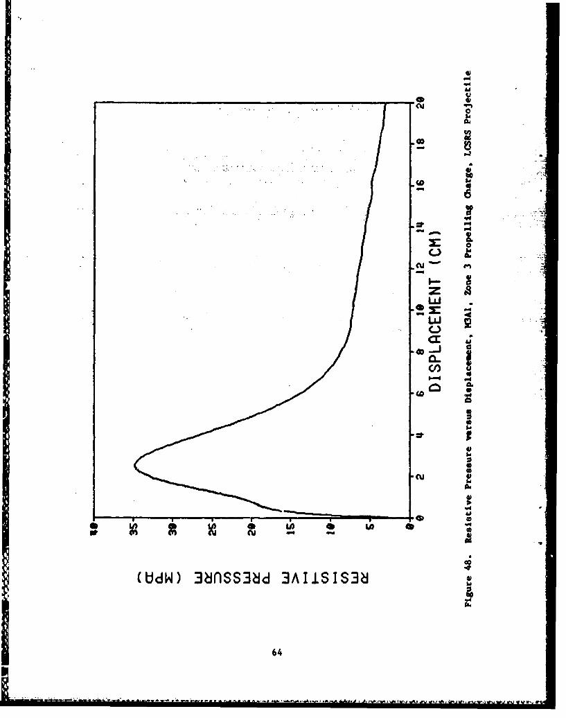
cu)
CuL
.40
40
U))cuu
64 6
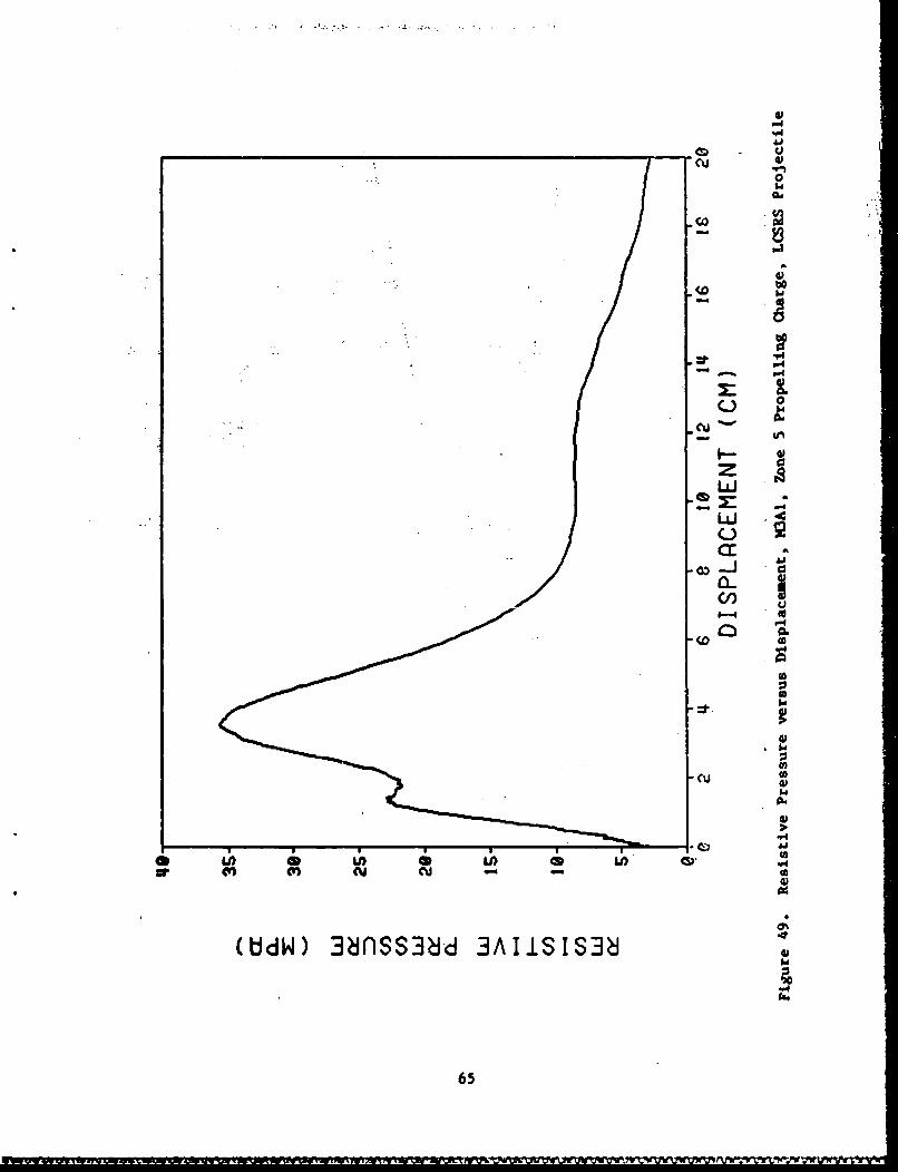
cw1
-4
a A
(IJJ
Q)-
40
LOi
-4
65~

"V4
90
666
-4
44 '
cu'
-CU
4'
CL40
C-)4.%.
(ddW)~Cl 3dS~d3AiI~
A - I
67'
scoop assembly. Because of the relative motion between the scoop andprojectile body during launch, the measured tangential acceleration was ofthe scoop aseembly and not the projectile. On subsequent rounds, theaccelerometers were mounted in an adapter that fastened to the wall of theprojectile and were encapsulated in the epoxy that was used for the ballast(Figure 25). This structure on several of the rounds broke loose duringlaunch and distorted the data. In response to the projectile community'sinterest in angular acceleration/torsional impulse measurements, four free-flight rounds, originally configured for evaluation of an experimentalpropelling charge, were also configured with accelerometers located in aemail metal box suspended "n the epoxy fill as shown in Figure 21.
The relationship between the angular acceleration, axial acceleration,
and the tangential acceleration is as follows:
8- ax T - at/r (5)
where: ; - angular acceleration
ax - axial acceleration
T - twist of the tube- I revolution / 20 calibers- 2.0268 radians / metre
(for 155-un tube)
at- tangential acceleration
r - radius of the tangent
If the rotating band immediately engraves the rifling and there is no freerun, the axial acceleration and tangential acceleration-time histories willhave identical shapes differing only by magnitude. The difference in theshapes of these two curves is a measure of the torsional impulse during theengraving process.
Unfortunately, accelerometers also measure any vibration of thestructure on which they are mounted. This effect can mask the desiredquantity being measured. The cross-axis sensitivity of the accelerometeralso distorts this measurement. It can be as much as five percentaccording to the manufacturer's specifications. Several of theaccelerometers used for these measurements were subjected to anacceleration, on a drop table, at right angles to the sensing axis to tryto determine the cross-axis characteristics. However, the transversemotion of the drop table caused substantial output and no conclusions couldbe made.
The tangential accelerometer is subjected to two cross-axisaccelerations. They are the axial acceleration of the projectile and thecentrifugal force of the spinning projectile. The acceleration due to thecentrifugal force is directed along a radius and is related to the axialacceleration by the relationships:
68
4fk
ar Vr2/R (6)
where: ar - radial acceleration
R - radius at Car)
Vr - velocity at R
ar - T2 Rvx 2
where: vx - axial velocity
-The radial acceleration-tim history should have a shape of the squaredaxial velocity curve and only differ in the magnitude.
Using a measured axial accelerstion for a 155-mm, M101 projectile andthe above relationships, the resultant cross-axis acceleration on atangential accelerometer located on a 4.29 cm radius is presented as Figure52. The acceleration vector is aligned with the projectile axis at thestart of motion, rotates 90 degrees during the in-tube iravel, and isaligned with the radius at projectile/tube separation. The tangentialacceleration for this location is 8.7Z of the axial acceleration.Therefore, several percent oi cross-axis sensitivity for the tsngentialaccelerometer would result in a significant distortion of the measurement.During the engraving region, the cross-axis influence is at the minimum.Therefore, indications of torsional impulse may be determined provided thevibrational component can be identified and separated from the torsionalimpulse.
The free-flight rounds, modified for angular acceleration measurements(Figure 21), were configured with a radial accelerometer located in thesmall metal box along with the tangential accelerometer. Figures 53, 54,and 55 present the unfiltered acceleration time histories for the axial,radial, and tangential acceleration respectively. This round was propelledwith 29 experimental charge made with slotted stick propellant (74 cmlong) and had a chamber pressure magnitude near that of a Zone 8. Themagnitude of the axial acceleration was corrected using the pressure-port-passage procedure as previously described. Unfortunately, there are notsimilar techniques for correcting the tangential and radial acceleration
2 6 F.W. Robbins and A.W. horst, "Detailed Characterization of The InteriorBallistics of Slorted Stick Propellant," BRL-TR-2591, Ballistic ResearchLaboratory, Aberdeen Proving Ground, MD, September 1984.
69
UW,
U) 4U) C
UV)
LjLl
4c
0)
700

Li)
CuI
0
'41
UU
Lh LA a U
(7) g-aMW
(S/S/)4) O I t~d31303
711

U),
L44
"ad
to
U)U- -- - - -- - A
Lo
W-4
0J
P-4
Laa
- - - - o - P (n 0
(S/S/WN NOI N143
72.

W4
0)
CA
LO 0
- 04
IV.
(U
(S/S/WA(1 o~I8130
U)W$W
73'

measurements. Past experience indicates that the magnitude of on-boardacceleration measurements are low. The radial and tangentialaccelerometers were located on 4.32 and 4.29 cm radii respectively. Thefrequency bandwidth of the telemetry system was 8 kHz and permitted passageof the vibration influence. The vibration component of the tangentialacceleration was large and the trace did not return to near baseline at thesame rate as the axial acceleration. This indicates the influence of thecross-axis component. Figure 56 presents the three acceleration-timehistories for this round after filtering at 2 kHz. The negative excursionof the radial acceleration is not explained. It is possible that it wascaused by a lateral motion of the projectile while being centered by theforcing cone.
The angular accelerations derived from the axial and tangentialaccelerations for this round are presented as Figures 57 through 60. Theseplots are filtered at 2,3,4, and 5 kiz respectively to try to eliminate thevibration component. A similar free-flight round was propelled by a chargemade of slotted granular (2.54 cm long) propellant. 2 6 A plot of theangular accelerations, filtered at 5 kHz, for this round is presented asFigure 61. It is obvious that the measurement of the torsional impulse, ifit exists, is somewhat masked by the structural vibration. Also, theeffect of the vibration and cross-axis sensitivity are apparent during thedown-tube travel. During the early motion, Figure 60 and 61 show therotating bands did not immediately engage tube rifling since the angularacceleration derived from the tangential acceleration lagged that derivedfrom the axial acceleration,
X. OONCLUSIONS
The telemetry system has been proven to be reliable for use as thedata link from the projectiles during the interior ballistic cycle. Thecommercial availability of the transmitting subsystems make this type ofmeasurement feasible fcr routine experiments. Since the LCSRS isoperational, the instrumentation can be reused, decreasing the costs pershot. Retrieving the telemetry transmitting system also permitsdetermination of failure modes when they occur. The failure modes of thetelemetry system for the expendable free-flight rounds were only surmised.
The interfacing of the transducers to the projectile and structuresthat house the transducers are problem areas that must be addressed. Forbetter measurements, an effort must be made to improve the design of themodifications to the projectiles and a more detailed analysis must be madeof the effect of the added structures. It was shown that vibrations wereintroduced by the added structure on the recoverable rounds.
Additional efforts are required to gain more confidence in the
74

Iad
len
Lan
P4cU)
V 4
Lý 04
f-
4i) (CJ *ý t4 4i (tJ * U), CU~ a' CctU 4a D t% WD U) (n) (V
75
4;
LAA
0 - P4im IdIzL
a UI= -J oU. cc
C.)
ýp5La 0LJ
. 'a
LA 0
P4
4S,
C4 40
(S/s/aUdN>) NO.I1LJd3130OU duifONbi%
76
U)
* .*LO
zz0
ag 'O
(A
ow dU (U LO Co * U 0-L x 3w w
(S/S/Gb~~~~0) NOC~1Ot0UfOb9K z
cci
77.
"4;
0
Ac
* "4
erý 0
CK w
C-) 0
w Aw
a. 0 L L
- 0ix 1w a,
aI
-+4 40
"4hiM
(S/SOUýJ) NQIUýJ1330U ddnO0
784
CA "XA..ib.F.1H IA.%AtI)~frUL VUVWLMUV*.PV" r
1.0 U)
-- 4
z *
x 0r
>, 0LIJ x CD c
0)
"14
(S/S/OddNU) NOI4310d8dn
----------------------------------
S S 5 5 5 5 * * *79
&0
----------------------------------
U)I Ad
U)
w s-
-a-
wI
0 6-6
Cc~
10
80)
a' .A p * -- a P

transducer calibrations. Techniques are required for the dynamiccalibration of the transducers over the range they will be used. It Isnecessary to accurately determine their linearity, hysteresis, andrepeatability. It is also necessary to determine the cross-axissensitivity of the accelerometers used for measuring tangentialacceleration and establish if super position exists so the axial componentof this measurement can be subtracted. Although the telemetry transmissionlink functions throughout most of the in-tube travel, the characteristicsof the transducers distort the data for tangential accelerationmeasurcments. It is obvious that additional research and development is.required in this area before routine measurements are made of the torsionalimpulse. Possible solutions of the problems are: mechanical filtering toeliminate the vibration component, developing transducers with minimumcross-axis sensitivity, and/or developing a new class of transducers thatmeasure the angular acceleration directly.
The data presented in this report are a small sample. Additional ,measurements are requirod to establish a data base large enough to beuseful as input parameters to new weapon systems designs and newlyformulated interior ballistic models.
XI. ACKNOWLEDGMENTS
The author is grateful to Messrs. C.R. Ruth, J.E. Bowen, and J.R.Hew.tt for their invaluable service of conducting the firing program andmanaging the LCSRS. Mr. J.L. Stabile was invaluable for his assistancewith the instrumenrttion, telemetry receivir- dystem, and data reduction.Mr. Ruth was particularly helpful with the BALDAS and instrumentation set-up. Messrs W.J. Cruickshank and J.O. Pilcher contributed many suggestionsduring the projectile modification and telemetry transmitting systemsdesign. Mr. F.W. Robbins provided guidance during data pvaluation. . ,'-
4
I ..
• 81
-. L v ~.. j7..Ah ~ N ~ F~tEr'.n2r

REFER{ENCES
1. E.B. Fisher, "Continued Development and Documentation of the CalspanInterior Ballistics Code," ARBRL-CR-0465, Calupan Corporation,Ballistic Research Laboratory, USA ARRADCOM, Aberdeen Proving Ground,MD, September 1981.
.2. J.W. Evans, "In-Bove Measurements of Projectile Acceleration and Base- Pressure Using an S-Band Telemetry System," Proceedings of The
International Telemetry Conference, Volume XI, October 1975.
"3. J.W. Evans, "In-Bore Measurements of Projectile Acceleration and Base
Pressure Using an S-Band Telemetry System," Proceedings of The Fuze/Munitions Environment Characterization Symposium II, October 1975.
4. J.W. Evans, "In-Bore Measurements of Projectile Acceleration and BasePressure Using an S-Band Telemetry System," Memorandum Report No. 2562,Ballistic Research Laboratories, Aberdeen Proving Ground, MD, December.175.
-5,' J.W. Evans, "Pressure and Acceleration Measurements In Large CaliberCannont," Proceedings of The Tenth Transducer Workshop, June 1979.
J.W. Evauc, 'Measurements On-Board A Projectile During The In-Tube, t•'.'• ravel Using An FM/FHI Telemeter," Proceedings of DZA-G-1060 Germany-,';
Unized States Ballistic Research and Development, October 1980.
, 7 . J.W. Evin-', "A Technique for Measuring Engraving and Bore Frictional.Forces in Large CAlibf.r Guns," Proceedings of the 1983 SANNAP
8. J.W. Evans, C.R. Ruth, and E.V. Clarke, Jr., "Soft Recovery Tests of A
155-mm Cannon Launched Guided Projectile, Type T," ARBRL-MR-03107,K "�Pllistic Rxsearnh Laboratory, USA ARRADCOM, Aberdeen Proving Ground,
MD, Wiy 1981.
9. M.K. Nichols and L.L. Rauch, Radio Telemetry, 2nd Edition, John W'.leyand Sons, Inc., Nw York, NY, 1956.
10, E.J. Halcin and J.A. Pratt, "Design of A Large Caliber Soft Recovery
Syi;tem For The l11ietic Research Laboratories," Contract Report No.308, Honeywell lnc., Ballistic Research Laboratories, Aberdeen Proving
Cround, MD, Alguat 1976. (AD #BO13626L)
11. J.'W. Evans, E.V. Clarke, Jr., and C.R. Ruth, "Large Caliber Projectile,SoftL ecovery," Pro'ieedings of The 1979 JANNAF Propulsion Meeting, CPIAPublication Number 300, Volume 1, March 1979.
12. E.V. Clarkc, Jr., C.R. Ruth, J.W. Evans, J.E. Bowen, J.k. Hewitt, andJ.L.. Stabile, "Large Caliber Projectile Soft Recovery," ARBRL-MR-03083,Ballictic Rei~earch Laboratory, USA ARRADCOM, Aberdeen Prpving Ground,1D, February 1981.
83
13. "Model 109A Pressure Transducer Instrumentation Manual," PCBPiezotronics, Inc., Buffalo, NY, 14225
14. "Model 305H Accelerometer Instrumentation Hanual," PCB Piezotronics,Inc., Buffalo, NY, 14225.
15. PCB Piezotronics, Inc., General Guide To ICP Instrumentation, PamphletG-0001, Buffalo, NY.
lb. L.A. Ware and H.R. Reed, Communication Circuits, 3rd Ed., John Wileyand Sons, Inc., New York, NY, 1958.
17. A. Adamian, *Voltage Regulator Handbook," Fairchild Camera andInstrument Corporation, Mountain View, CA, 1978
18. C.L. Henry, R.L. Martz, and E.M. Wineholt, "An Improved Procedure ForThe Reduction of Interior Ballistic Data Recorded On Analog Tape,"Memorandum Report No. 2374, Ballistic Research Laboratories, AberdeenProving Ground, MD, April 1974. (AD #919924L)
19. Telemetry Working Group, Inter-Range Instrumentation Group, RangeCommanders Council, Telemetry Standards, Document 106-71, White SandsMissile Range, NM, 88002.
20. W.J. Cruickshank, "A Feasibility Test of An "S" Band Telemetry SystemFor Making In-bore Projectile Measurements," Memorandum Report No.2335, Ballistic Research Laboratories, Aberdeen Proving Ground, MD,October 1973.
21. W.J. Cruickshank, "Radio Telemetry Formula Applications, A PracticalUsers Guide," ARBRL-MR-03364, Balltstic Research Laboratory, AberdeenProving Ground, MD, August 1984.
22. M. Schwartz, "Information Transmission, Modulation, and Noise," McGraw-
Hill Book Company, INc., New York, NY, 1959.
23. A.Z. Schmidlin, "Torsional Impulse In Gun Launched Projectiles," ARLCD-TR-b0037, Large Caliber Weapons Systems Laboratory, USA ARRADCOM,nover, NJ, March 1981.
24. Minutes of Meeting, "Measurements of Torsional Impulse Using In-BoreTelemetry," Program Manager/Cannon Launched Weapon Systems, ARRADCOM,Dover, NJ, 5 March 1980.
25. Minutes of Meeting, "Internal Ballistics Characterization Briefing,"Project Manager for Nuclear Munitions, ARRADCOM, Dover, NJ, 28 April1981.
26. F.W. Robbins and A.W. Horst, "Detailed Characterization of The InteriorBallistics of Slotted Stick Propellant," BRL-TR-2591, RallisticResearch Laboratory, Aberdeen Proving Ground, MD, September 1984.
___ 84
DISTRIBUTION LIST
No. Of No. Ofcopies Oreanization Cope OrgaIation
12 Administrator I OenderDefense Technical Info Center US Army Materiel OmeandATTN: DTIO-DDA ATTN: AMQ)RA-STCameron Station 5001 Eisenhower Avenue
* Alexandria, VA 22304-6145 Alexandria, VA 22333-5001
1 Commander 1 CommanderUSA Concepts Analysis Agency US Army Materiel ommandATTN; D. Hardison ATTN: AMCDE-DW8120 Woodmont Avenue 5001 gisenhower AvenueBethesda, MD 20014-2797 Alexandria, VA 22333-5001
1 HQDA/DAMA-ZA 5 Project ManagerWashington, DC 20310-2500 Cennon Artillery Weapoas
Systm, ARD.C, AMC=hi1 HQDA, DAHA-CSM, E. Lippi ATTN: AkCP-CW,
Washington, DC 20310-2500 P. Monks
AMCPM-COWI HQDA/SARDA AMCNMoO8
Washington, DC 20310-2500 H. Fsette' . =. . -, •AMCPH '- GI
I Commander R. De~leineUS Army War College H. HassmannATTN: Library-F?229 Dover, NJ 07801-5001Carlisle Barracks, PA 17013
1 Project Manager1 US Army Ballistic Missile Nuclear Munitions
Defense Systems Command A)C, AMCCOM- Advanced Technology Center ATTN: AMCF14-NUC, B. Painter
P. 0. Box 1500 Dover, NJ 07801-5001Huntsville, AL 35807-3801
2 Project Manager1 Chaire Munitions Production baseDOD Explosives Safety Board Modernization and ExpansionRoom 856-C ATTN: AMtCP-PBM, A. SiklosiHoffman Bldg. 1 AMCPM-PBH-E, L. Laibson2461 Eisenhower Avenue Dover, NJ 07801-5001Alexandria, VA 22331-9999
3 Project ManagerI Commander -Tank Main Armament System
""US Army Materiel Command ATTNs AMCPM-TMA, K. RussellATTh: AMCPK-GCQ-WF AMQPM-TMA- 1055001 Eisenhower Avenue AMCPM-TMA- 120Alexandria, VA 2S333-5001 Dover, NJ 07801-5001
1 CommanderUS Army Watervliet ArsenalATTN: SARWV-RD, R. ThierryWatervliet, NY 12189-5001
S. - --- - - - - . . ..0

DISTRIBUTION LIST
No. Of No. Of
Sope Organization Copies Organization
22 Commander 1 DirectorUS Army ARDC, AMCCOM Benet Weapons Laboratory
ATTN: SMCAR-TSS Armament R&D Center
SMCAR-TDC US Army AMCODH
SMCAR-LC ATTN: SMCAR-LCB-TLLTC N. Barron Watervliet, NY 12189-5001
SMCAR-LCAA. Beardell I CommanderD. Downs US Army Aviation Research
S. Einstein and Development Command
S. Westley ATTN: AMSAV-ES. Bernstein 4300 Goodfellow Blvd.C. Roller St. Louis, MO 63120-1702
J. RutkowskiSMCAR-LCB-I I Commander
D. Spring US Army TSARCOMSMCAR-LCE 4300 Goodfellow Blvd.
SMCAR-LCH-E St. Louis, MO 63120-1702
S. KaplowitzSMCAR-LCS 1 DirectorSMCAR-LCU-CT US Army, Air Mobility Research
E. Barrieres And Development Laboratory
R. Davitt Ames Research Center
SMCAR-LCU-CV Moffett Field, CA 94035-1099
C. MandalaSMCAR-LCW-A I Commander
M. Salsbury US Army Communications -
SMCAR-S CA Electronics Command
L. Stiefel ATTN: AMSEL-ED
B. Brodman Fort Monmouth, NJ 07703-5301
SMCAR-TSE-ITL. Glass I CommanderD. Everswick ERADCOM Technical Library
Dover, NJ 07801-5001 ATTN: DELSD-L (Report Section)Fort Monmouth, NJ 07703-5301
4 CommanderUS Army Armament Munitions 1 Commander
and Chemical Command US Army Harry Diamond Lab.
XTTN SMCAR-ESP-L ATTN: DELHD-TA-L
Rock Island, IL 61299-7300 2800 Powder Miill RoadAdelphi, MD 20783-1145
HQDADAMA-ART-M I CommanderWashington, DC 20310-2500 US Army Missile Command
ATTN: AMSMI-0MRedstone Arsenal, AL
35898-5249
96

DISTRIBUTION LIST
No. Of No. OfCopies Organization Copies Organization
1 Commander, U.S. Army Missile 1 PresidentCommand, Research, Development US Army Armor & Engineer& Engineering Center, BoardATTN: AMSMI-RD ATfN: ATZK-AD-SRedstone Arsenal, AL 35898 Fort Knox, KY 40121-5200
• Director, U.S. Army Missile a Project ManagerIntelligence Center I tank gev
•ATTT: AILA-M-YM) M4-60 Tank DevelopmentATTN: AW>-S60TD
Redstone Arsenal, AL 35898-5500 ATTN: A!40'-M6OTDWarren, MI 48092-2498
1 DirectorI Commandant US Army TRADOC Systems
US Army Aviation School Analysis ActivityATTN: Aviation Agency ATTN: ATAA-SLFort Rucker, AL 36360 White Sands Missile Range,
NM 880021 Commander-_ US Army Tank Automotive I Comuander
Command . US Army Training & DoctrineATTN: AMSTA-TSL CotmmndWarren, MI 48092-2498 ATTN: ATOC-MA/ MAJ Willi.ams
Fort Monroe, VA 236511 Commander
US Army Tank Automotive 2 CommanderCommand US Army Materials and
ATTN: AHSTA-CG Mechanics Research CenterWarren, HI 48092-2498 ATTN: AflXMR-ATL
Tech Library.Project Manager Watertown, MA 02172
Improved TOW VehicleATTN: AMCPM-ITV I CommanderUS Army Tank Automotive US Army Research Office
Command ATTN: Tech LibraryWarren, MI 48092-2498 P. 0. Box 12211
Research Triangle Park, NC2 Program Manager 27709-2211
MI Abrams Tank SystemATTN: AMCPM-GMC-SA, I Commander
T. Dean US Army Belvoir ResearchWarren, MI 48092-2498 & Development Center
ATTN: STRBE-WCProject Manager Fort Belvoir, VA 22060-5606Fighting Vehicle SystemsATTN: AMH-NVSWarren, MI 48092-2498
87
DISTRIBUTION LIST
No. Of No. OfCopies Organization Copies Organization
CommanderUS Army Logistics Mgmt CtrDefense Logistics StudiesFort Lee, VA 23801
Commandant 1 Office of Naval ResearchUS Army Infantry School ATTN: Code 473, R. S. tLllerATTN: ATSH-D--CSO-OR 800 N. Quincy StreetFort BeSning, GA 31905 Arlington, VA 22217-9999
I President 3 CommandantUS Army Artillery Board US Army Armor SchoolFt. Sill, OK 73503-5600 ATTN: ATZK-W)-KS
M. FalkovitchCommandant Armor AgencyUS Army Command and Fort Knox, KY 40121-5215General Staff CollegeFort Leavenworth, KS 66027 2 Commander
Naval Sea Systems Command1 Commandant ATMl4: SEA 62R
US Army Special Warfare SEA 64School Washington, DC 20362-5101
ATTN: Rev & Tng Lit DivFort Bragg, NC 28307 1 omnder-
Naval Air System. Command y
3 Commander ATTN: AIR-954-Tech LibRadford Army Ammunition Plant Washington, DC 20360ATTN: SMCRA-QA/II LIBPadford, VA 24141-0298 1 Assistant Secretary of the
Navy (R, E, and 8)Commander ATITI: R. ReichenbachUS Army Foreign Science &Room 5E787
Technology Center Pentagon Bldg.ATTN: AMXST-MO-3 Washington, DC 20350220 Seventh Street, NECharlottesville, VA I Naval Research Lab
22901-53S" Tech LibraryWashington, DC 20375
2 CommandantUS Army Field Artillery 5 Commander
Center 6 School Naval Surface Weapons CenterATTN: ATSF-OD-iW, B. Willis ATTN: Code G33, J. L. East
Ft. Sill, OK 73503-5600 W. BurrellJ. Johndrow
1 Commander Code G23, D. HcClureUS Army Development and Code DX-21 Tech Lib
Employment Agency Dahlgren, VA 22448-5000ATTN: MODE-TED-SABFort Lewis, WA 98433-5099
S88
DISTRIBUTION LIST
No. Of No. Ofcopies Organization copies Organization
2 Comander 6 Commander1JS Naval Surface Weapons Naval Ordnance Station
Center ATTN: P. L. StangATTN: J. P. Coneaga J. Birkett
C. Gotzmer L TorreysonIndian Bead, MD 20640-5000 T. C. Smith
D. Brooks4 Commander Tech Library
Naval Surface Weapons Center Indian Bead, MD 20640-5000ATTh: S. Jacobs/Code 240
Code 730 1 AFSC/iDOAK. Kim/Code R-13 Andrews AFB, MD 20334R. Bernecker
Silver Spring, MD 20903-5000 3 AFRPL/DY, Stop 24ATTN: J. Levine/DYC1
.-2 Commanding Officer R. Corley/DYCNaval Underwater Systems D. Williaus/DYCC
Center Edwards AFB, CA 93523-5000Energy COnversion Dept.ATTN: -. 0DE 5B331, R. S. Lazar .1 APFDL
Tech Lib ATTN: TST-LibNewport, RI 02840 Wright-Patterson AFB,
OH 45433
4 CommanderONaval Weapons Center 1 AFRPL/TSTL (Tech Library)ATTN: Code 388, R. L. Derr Stop 24
C. F. Price Edwards AFB, CA 93523-5000T. logga
Info. Sci. Div. 1 AFATL/DLYVChina Lake, CA 93555-6001 Eglin AFB, FL 32542-5000
2 Superintendent 1 AFATL/DLXPNaval Postgraduate School Eglin APB, FL 32542-5000Dept. of Mechanical
Engineering 1 AFATL/DLJEMonterey, CA 93943-5100 Eglin AFB, FL 32542-5000
Program Manager 1 AFATL/DLODLAFOSR ATTN: Tech LibDirectorate of Aerospace Egltn APB, FL 32542-5000,
SciencesATTNi L. H. Caveny 1 AFWL/SULBoiling AFB, DC 20332-0001 Kirtland AFB, NM 87117
10 Central Intelligence AgencyOffice of Central ReferenceDissemination BranchRoom GE-47 HQSWashington, D.C. 20502
89

DISTRIBUTION LIST
No. Of No. OfCopies Organization Copies Organization
NASA/Lyndon B. Johnson Space 2 Calspan CorporationCenter ATTN: C. Morphy
ATTN: NKS-22, Library P. 0. Box 400Sectin Buffalo, NY 14225-0400
Houston, TX 770541 Foster Miller Associates
AFELH, The Rand Corporation ATTN: A. EricksonATTN: Library Or 135 Second Avenue1700 Main Street Waltham, HA 02154Santa Monica Ch
90401-3297 1 General Electric CompanyArmament Systems Dept.
General Applied Sciences Lab ATTN: M. J. Bulman,ATTN: J. Erdos Room 1311
Herrick & Stewart Avenues 128 Lakeside AvenueWestbury Long Isld, NY 11590 Burlington, VT 05401-4985
I I Corporation I ILTRI
ATTN: J. Rlebert ATTN: H. J. KleinJ. Frankle 10 W. 35th Street
"P. O. Box 6767 Chicago, IL 60616-3799Baltimore, HD 21204
1 Hercules Inc.I Aerodyne Research, Inc. Allegheny Ballistics
Bedford Research Park LaboratoryATTN: V. Yousefian ATT-N: R. B. MillerBedford, MA 01730-1497 P. 0. Box 210
Cumberland, MD 21501-02101 Aerojet Ordnance Company
ATTN: D. Thatcher 1 Hercules, Inc.2521 Michelle Drive Bacchus WorksTustin, CA 92680-7014 ATTN: K. P. McCarty
P. 0. Box 98Aerojet Solid Propulsion Co. Magna, UT 84044-0098ATTN: P. KicheliSacramento, CA 95813 1 Hercules, tnc.
Radford Army Aniunition PlantAtlantic Research Corporation ATTN: J. PierceATTN: H. K. King Radford, VA 24141-02995390 Cheorokee AvenueAlexandria, VA 22312-2302 1 Honeywell, Inc.
Defense Systems Division
AVO) Everett Rach Lab ATTN: C. HargreavesATTN: D. Stickler 5901 So. City Road 18
2385 Revere Beach Parkway Edina, MN 55436Everett, HA 02149-5936
90

DISTRIBUTION LIST
No. Of No. OfCopies Organization Copies Organization
I Honeywell, Inc. 1 Princeton Combustion ResearchDefense Systems Division Lab., Inc.ATTN: F. Williamson ATTN: M. Sumerfield23100 Sugar Bush Road 475 US Highway One"" k River, MN 55330 Monmouth Junction, NJ
08852-9650"Lawrence Livermore National
- Laboratory 2 Rockwell InternationalATTN: L-355, Rocketdyne Division
A. Buckingham ATTN: BAO8 J. 8. FlanaganM. Finger J. Gray
P. 0. Box 808 6633 Canoga AvenueLivermore, CA 94550-0622 Canoga Park, CA 91303-2703
A Lawrence Livermore National 4.Sandia National LaboratoriesLaboratory ATTN: N. Lapetina, 8152
ATTN: L-324 R. Peterson, 8173H. O)nstantino G. Bendetti, 8241
P. 0. Box 808 D. Stoner, 8173Livermore, CA 94550-0622 4 P. 0. Box 969
Livermore, CA 94550=,1 Olin Corporation
Badger Army Ammunition Plant .1 Science Applications, Inc.ATTN: R. J. Thiede ATTN: R. B. EdelmanBaraboo, WI 53913 23146 Qzmorah Crest Drive
Woodland Hills, CA 91364-3710
.Olin Corporation"' Smokeless Powder Operations 3 Thiokol Corporation
ATTN: D. C. Mann Huntsville DivisionP.O. Box 222 ATTN: D. FlaniganAt. Harks, FL 32355-0222 R. Glick
"Tech Library
Paul Gough Associates, Inc. Huntsville, AL 35807ATTN: P. S. GoughP. 0. Box 1614, 1 Scientific Research1048 South St. Assoc., Inc.Portsmouth, NH 03801-1614 ATTN: H. McDonald
P.O. Box 498Physics International Company Glastonbury, Cr 06033-0498ATTN: Library
H. Wayne Wampler 1 Thiokol Corporation2700 Merced Street Wasatch DivisionSan Leandro, CA 94577-5602 ATTN: J. A. Peterson
P. 0. Box 524Brigham City, UT 84302-0524
91

DISTRIBUTION LIST
No. Of No. OfCopies Organization Copies Organization
"2 Thiokol Corporation I University of IllinoisElkton Division Dept of Mech/Indust EngrATTN: R. Biddle ATTN: H. Krier
Tech Lib. 144 HEB; 1206 N. Green St.P. 0. Box 241 Urbana, IL 61801-2978Elkton, MD 21921-0241
I University of Massachusetts2 United Technologies Dept. of Mechanical
-,Chemical Systems Division EngineeringR--TN: K. Brown ATTN: K. Jakus
j .. Tech Library Amherst, MA 01002-0014P. 0. Box 358
-Sunnyvale, CA 94086-9998 I University of Minnesota
TechnologyInc.,-;-Dept. of Mechanical .. i'Veritay Technology, Inc. Engineering
'-'-ATTN: E. Fisher ATrN: E. Fletcher4845 Millersport Hwy. Minneapolis, M0 55414-3368P. 0. Box 305"East Amherst, NY 14051-0305 1 ,Case Western Reservei Universal Propulsion Company - - ... University
I Universa Propulsin .Division of AerospaceATTN: H. J. HcSpadden SciencesBlack Canyon Stage I ATTN: J. TienBox 1140 Cleveland, OH 44135Phoenix, AZ 85029 l a 0 4
3 Georgia Institute of TechBattelle Memorial Institute School of Aerospace Eng.ATTN: Tech Library ATTN: B. T. Zinn505 King Avenue E. PriceColumbus., OH 43201-2693 W. C. Strahle
Atlanta, GA 30332I Brigham Young University
Dept. of Chemical Engineering I Institute of Gas TechnologyATTN: M. Beckstead ATTN: D. Gidaspow
. Provo, UT 84601 3424 S. State StreetChicago, IL 60616-3896
I California Institute of Tech a I 6204 Karman Lab I Johns Hopkins University
" Main Stop 301-46 Applied Physics LaboratoryATTN: F. E. C. Oalick Chemical Propulsion1201 E. California Street Information AgencyPasadena, CA 91109 ATTN: T. Christian
Johns Hopkins RoadCalifornia Institute of Tech Laurel, MD 20707-0690Jet Propulsion LaboratoryATTN: L. D. Strand4800 Oak Grove DrivePasadena, CA 91109-8099
92

DISTRIbUTION LIST
No. Of No. Ofcopies Organization Copies Ornanization
Massachusetts Institute of 1 Rutgers UniversityTechnology Dept. of Mechanical and
Dept of Mechanical Engineering Aerospace EngineeringATTN: T. Toong ATTNI S. Temkin77 Massachetts Avenue University Heights CampusCambridge, MA& 02139-4307 Now Brunavick, NJ 08903
1 .University of MichiganGas Dynamics Laboratory I University of SouthernAerospace Engineering Bldg. California
S-- ATTN: C. M. . eth Mechanical Engineering Dept.Ann Arbor, MI 48109-2140 ATTN: OH200, M. Gerstein
Los Angeles, Ch 90089-5199
I Pennsylvania State University 2 University of UtahDept. Of Mech. Engineering Dept. of Chemical EngineeringATTN: K. Kuo ATTN: A. BaerUniversity Park, PA G, nlandro
16802-7501 Salt Lake City, UT 84112-1194
. .I _-1 Purdue University 1 Washington State University, . •School of Mechanical Dept. of Mechanical .. .
Engineering EngineeringATTN: J. R. Osborn ATTN C.iTr Crowe
TSPC ChaffeeHa Pullma, WA 99163-5201HlWest Lafayette, IN 47907-1199 l
SRI InternationalPropulsion Sciences Division Aberdeen Proving GroundATTNt Tech Library333 Ravensvood Avenue Dir, USAMSAAMenlo Park, CA 94025-3493 ATTN: AKXSY-D
A•XSY-MP, H. CohenRensselaer Polytechnic Inst. Odr, USATBOOMDepartment of Mathematics ATTN: AMSTE-TO-FTroy, NY 12181 AHSTE-Q4-F, L. Nealley
cdr, CSTADirector ATTNz STECS-AS-H, R. HendricksonLos Alamos Scientific Lab ATTN: STECS-DA-J, S. WaltonATTN: T3, D. Butler L. Prancis
M. Division, IB. Craij ATTN: STECS-SN-BM, V. Betzo]dP. 0. Box 1663 Cdr, CJDC, AHCCDMLos Alamos, NM 87544 ATTN: SMC•R-RSP-A
SMCCR-HUStevens Institute of SMCCK-SPS-IL
TechnologyDavidson LaboratoryATTN: R. RcAlevy, IIICastle Point StationHoboken, NJ 07030-5907
93
USER EVALUATION SHEET/CHANGE OF ADDRESS
This Laboratory undertakes a continuing effort to improve the quality of thereports it publishes. Your comments/answers to the items/questions below willaid us in our efforts.
1. BRL Report Number Date of Report
2. Date Report Received
3. Does this report satisfy a need? (Comment en purpose, related project, orother area of interest for which the report will le used.)
,-4. How specifically, is the report being used? (Information source, designdata, procedure, source of ideas, etc.)
S. Has the information in this report led to any quantitative savings as far'as man-hours or dollars saved, operating costs avoided or efficiencies achieved,etc? If so, please elaborate.
-. General Comments. What do you think should be changed to improve futurereports? (Indicate changes to organization, technical content, format, etc.)
Name
CURRENT Organization
ADDRESS Address
City, State, Zip
7. If indicating a Change of Address or Address Correction, please provide theNew or Correct Address in Block 6 above and the Old or Incorrect address below.
Name
OLD OrganizationADDRESS
Address
City, State, Zip
(Remove this sheet along the perforation, fold as indicated, staple or tapeclosed, and mail.)

h
. . . . . . . . .- FOLD HERE . . . .. . . . .
Director 1111NO POSTAGEU.S. Amy Ballistic Research Laboratory 1NECESSARYATTN: SLCNR-DD-T ' IF HAILEDAberdeen Proving Ground, MI) 21005-5066 IN THE
[UNITED STATESOFFICIAL SUSIN £55PSN OO ,IA," M iBUSINESS REPLY MAIL rn
MSTCASS IRIMN01-062WASMNINTO1,OCl
POSTA0GE W -LL E MaO BY EPMRTMENT OF THE AiY -
DirectorU.S. Amy Ballistic Research LaboratoryATTN: SLCBR-DD-TAberdeen Proving Ground, MD 21005-9989
. . .. . . . .-FOLD HERE - - • . ..--
: T -
S.. . ... . .. . .. . . . .. . . .. ... . .. ... . .. . .. . . .. .. . ... .. . . .. . .. . . .. . . . ... . . . . . . a . . . . .. . .. . . . .. ... . . . . .. . . . . . . , . . . . _
• • , i ii I I I I4