mea 2017 nec grounding and bonding part 2 minnesota
TRANSCRIPT
11/13/2018
1
MEA 2017 NECGrounding and Bonding
Part 2
2-hour class presented by
Minnesota Electrical Association
This seminar will satisfy the 2-hour electrical code training for electricians required by the State of Minnesota.
Minnesota Electrical Association 1
Acknowledgements
Some material and illustrations presented are with permission of Cengage Learning from: Electrical Grounding and Bonding 2014 by Phil Simmons
The National Electrical Code (NEC)® is: Document 70 from the National Fire Protection
Association (NFPA)
11/13/2018
2
Objectives :
Systems required to be grounded,◦ Permitted but not required to be grounded
◦ Systems not permitted to be grounded
Requirements for grounded systems Installing and sizing grounded service - and
system conductors System conductors that are required to be
grounded
3
Objectives :
Function of, and sizing, main and system bonding jumpers
Grounding requirements for separately derived systems
Grounding for two or more buildings supplied by a feeder or branch circuit
Portable and vehicle-mounted generators High-impedance grounded neutral systems
4

11/13/2018
3
One line grounding
5
250.20 AC Circuits and Systems to be Grounded
Alternating-current circuits and systems are required to be grounded (connected to earth) if the system meets any of the conditions in 250.20(A), (B), (C), or (D)
Voltage level supplied by the system is considered as a general rule
Use of neutral for 3-phase systems also considered
6

11/13/2018
4
250.20 AC Circuits and Systems to Be Grounded
Some circuits and systems are permitted to be grounded - 250.20(C) other than portable or mobile equipment. (see 250.188)
If systems are grounded, the methods must comply with Article 250
250.21 - Some circuits are not required to be grounded. Parts (A)–(C)
7
250.20 Informational Note; Example Corner Grounded Delta Systems Systems permitted but
not required to be grounded
Must meet 150-volt test of 250.20(A)(1) (if X-fmr exceeds 150V to grnd)
If grounded, must comply with all other rules of Article 250
8Copyright © Cengage Learning
11/13/2018
5
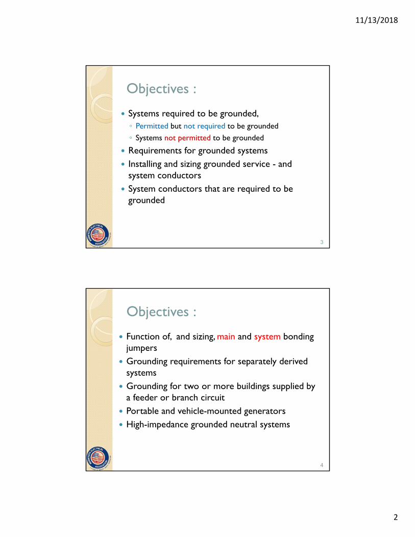
250.20(A) AC Systems of Less Than 50 Volts
AC systems of less than 50 volts are required to be grounded under any of the following conditions:
9Copyright © Cengage Learning
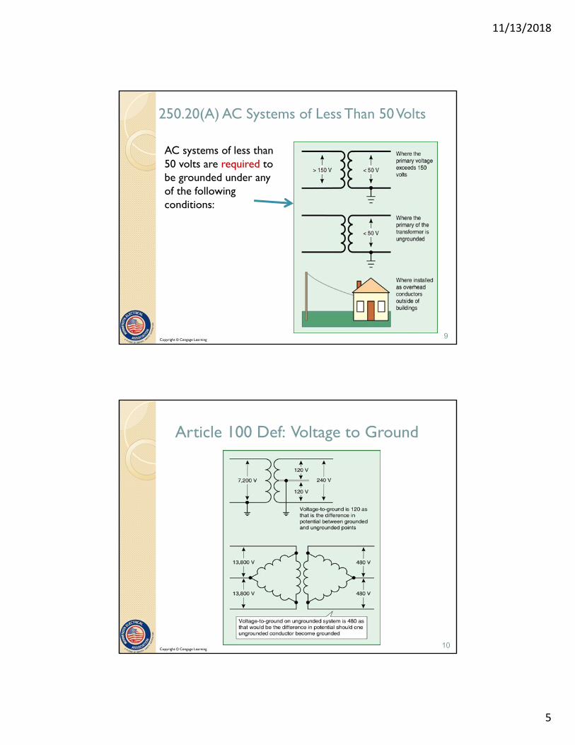
Article 100 Def: Voltage to Ground
10Copyright © Cengage Learning

11/13/2018
6
250.20(B) AC Systems of 50 to 1000 Volts
AC systems of 50 to 1000 volts that supply premises wiring and premises wiring systems are required to be grounded under specific conditions:
(1) Where the system can be grounded so the maximum voltage to ground on the ungrounded conductors does not exceed 150 volts
11
Systems 50 to 1000 Volts Required to be Grounded
12Copyright © Cengage Learning
11/13/2018
7
Systems 50 to 1000 Volts Required to be Grounded
(2) Where the system is 3-phase, 4-wire, wye connected in which the neutral is used as a circuit conductor
Typical voltages:
208Y/120; 480Y/277;
575Y/332; 600Y/346
13Copyright © Cengage Learning
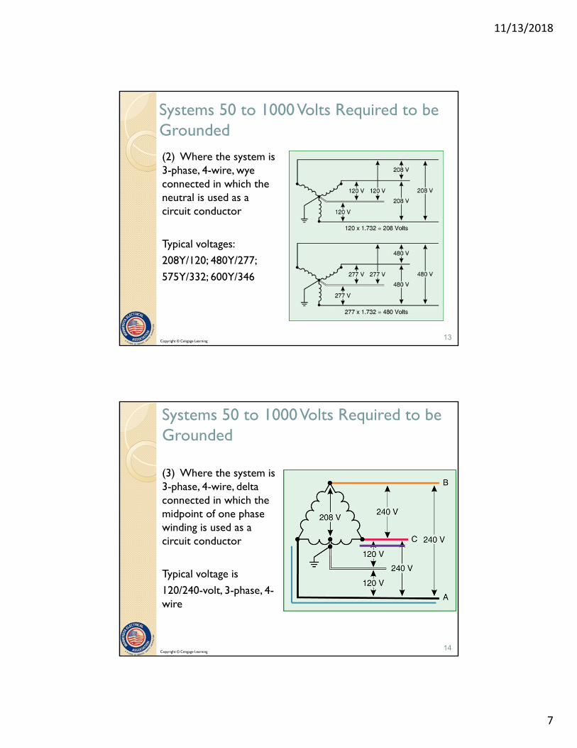
Systems 50 to 1000 Volts Required to be Grounded
(3) Where the system is 3-phase, 4-wire, delta connected in which the midpoint of one phase winding is used as a circuit conductor
Typical voltage is
120/240-volt, 3-phase, 4-wire
14Copyright © Cengage Learning

11/13/2018
8
Copyright © Cengage Learning
250.20 (C) AC systems over 1000 V
Ac systems that supply mobile or portable equipment shall be grounded as specified in 250.188. Grounding of systems that supply mobile or portable equipment
If supplying other than mobile of portable equipment, the systems are permitted to be grounded

11/13/2018
9
250.20 (D) Impedance grounded neutral systems
Impedance grounded neutral systems shall be grounded as per 250.36 or 250.187
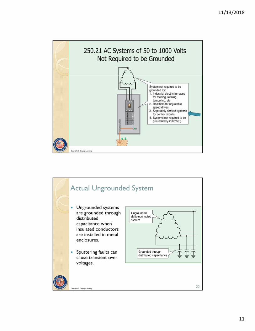
250.21 AC Systems of 50 to 1000 Volts Not Required to be Grounded (but may be)
1. Electric systems used exclusively to supply industrial furnaces for melting, refining, tempering, and the like.
2. Separately derived systems used exclusively for rectifiers that supply only adjustable-speed industrial drives.
18

11/13/2018
10
250.21 AC Systems of 50 to 1000 Volts Not Required to be Grounded
3. Separately derived systems supplied by transformers that have a primary voltage rating 1000 volts or less, provided all the following conditions are met:
a) The system is used exclusively for control circuits
b) Qualified persons service the installation
c) Continuity of control power is required
19
250.21 AC Systems of 50 to 1000 Volts Not Required to be Grounded
4. Other systems that are not required to be grounded in accordance with the requirements of 250.20(B)
20
11/13/2018
11
Copyright © Cengage Learning
Actual Ungrounded System
Ungrounded systems are grounded through distributed capacitance when insulated conductors are installed in metal enclosures.
Sputtering faults can cause transient over voltages.
22Copyright © Cengage Learning

11/13/2018
12
250.21(B) Ground Detection Required
Ground detection required for any ungrounded system from A(1) through A(4) from 120 V to 1000V
Various types and levels of sophistication are available.
The detection system is to be as close as practicable to the system supply
NEC is silent on the type installed
23Copyright © Cengage Learning
Marking Requirement
250.21(C) Marking. Ungrounded systems shall be legibly marked “Caution Ungrounded System Operating __X___ Volts Between Conductors” at the source or first disconnecting means of the system. The marking shall be of sufficient durability to withstand the environment involved.
Additionally -408.3(F)(2) Panelboards -Ungrounded Systems.
“Caution Ungrounded System Operating _____ Volts Between Conductors”
24

11/13/2018
13
250.22 Circuits Not to Be Grounded
1. Circuits for electric cranes operating over combustible fibers in Class III locations as provided in 503.155
25Copyright © Cengage Learning
250.22 Circuits Not to Be Grounded
2. Circuits in health care facilities as provided in 517.61- Classified Anesthetizing locations and 517.160- Isolated power systems
Uses Line Isolation Monitor (LIM)
26Copyright © Cengage Learning

11/13/2018
14
250.22 Circuits Not to Be Grounded
3. Circuits for equipment within the electrolytic cell line working zone as provided in Article 668
27Copyright © Cengage Learning
250.22 Circuits Not to Be Grounded
4. Secondary circuits of lighting systems as provided in 411.6(A): Lighting circuits at 30V or less – Class 2
28Copyright © Cengage Learning

11/13/2018
15
250.22 Circuits Not to Be Grounded
5. Secondary circuits of lighting systems as provided in 680.23(A)(2): Underwater luminaires
29Copyright © Cengage Learning
250.22 Circuits Not to Be Grounded
6. NEW Class 2 load side circuits for suspended ceiling low voltage power grid distribution systems as provided in 393.60(B)

11/13/2018
16
250.24(A) System Grounding Connections for service supplied AC systems
A premises wiring system supplied by a grounded ac service must have a grounding electrode conductor connected to the grounded service conductor at each service per 250.24(A)(1) - (A)(5)
31Copyright © Cengage Learning
250.24(A)(1) General
GEC connection shall be made at any accessible point from the load end of the overhead service conductors, service drop, underground service conductors, or service lateral to, including the terminal or bus to which the grounded service conductor is connected at the service disconnecting means.
32Copyright © Cengage Learning

11/13/2018
17
Generally Accepted Locations
1. At the weather-head for overhead services
2. At the meter socket or current transformer enclosure (verify with the utility and electrical inspector)
3. At a wireway or auxiliary gutter on the line side of the service equipment
4. Within the service equipment enclosure
33Copyright © Cengage Learning
250.24(A)(2) Outdoor Transformer
If the transformer supplying the service is located outside, at least one additional grounding connection is required to be made from the grounded service conductor to a grounding electrode
* Exception for high impedance grounded systems
34Copyright © Cengage Learning
11/13/2018
18
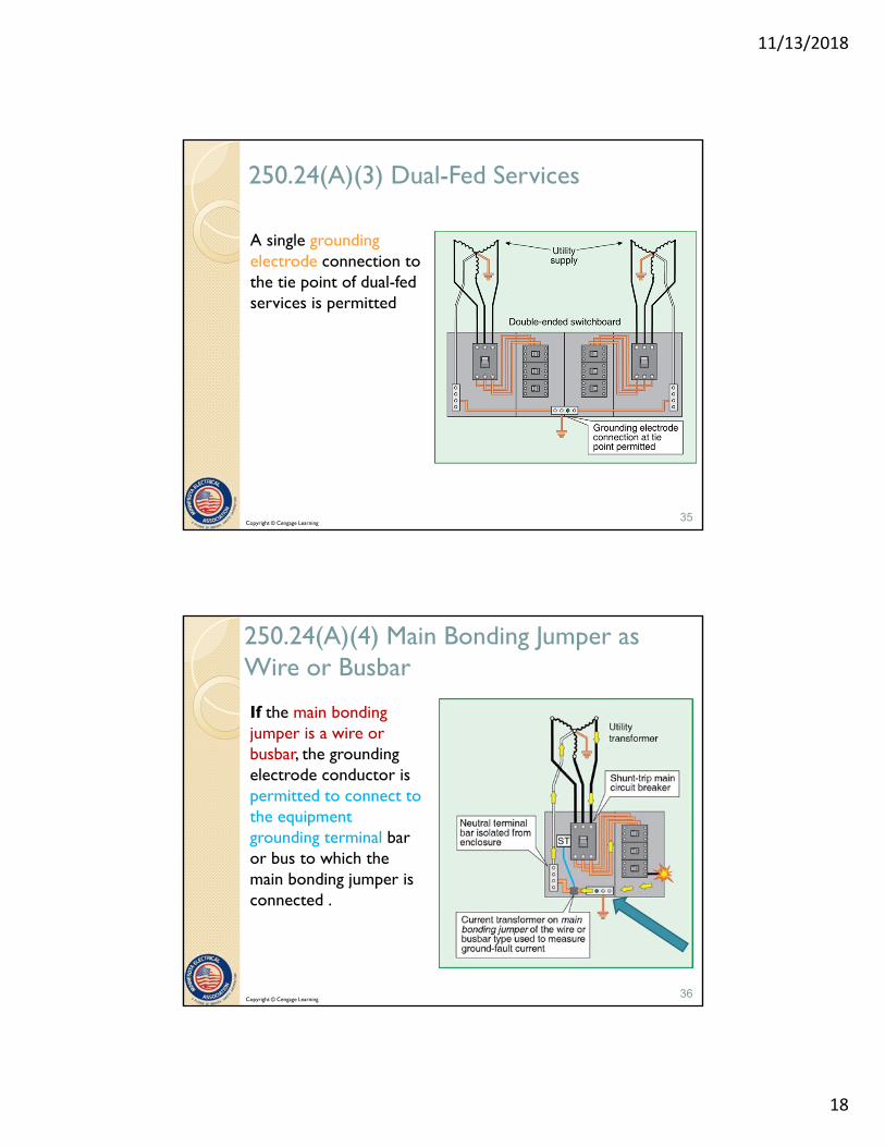
250.24(A)(3) Dual-Fed Services
A single grounding electrode connection to the tie point of dual-fed services is permitted
35Copyright © Cengage Learning
250.24(A)(4) Main Bonding Jumper as Wire or Busbar
If the main bonding jumper is a wire or busbar, the grounding electrode conductor is permitted to connect to the equipment grounding terminal bar or bus to which the main bonding jumper is connected .
36Copyright © Cengage Learning

11/13/2018
19
250.24(A)(5) Load-Side Grounding Connections
A grounding connection is not permitted on the load side of the service disconnecting means unless permitted in Article 250. (connections other than service panel as in SDS)
IN: See 250.30 for separately derived systems, 250.32 for buildings or structures supplied by a feeder or branch circuit and 250.142 for other permitted uses.
37
38
Feeders
Copyright © Cengage Learning
11/13/2018
20
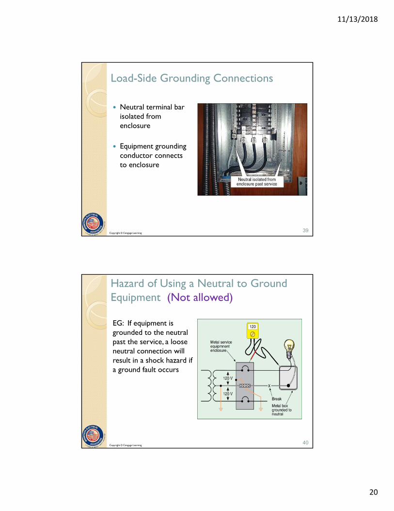
Load-Side Grounding Connections
Neutral terminal bar isolated from enclosure
Equipment grounding conductor connects to enclosure
39Copyright © Cengage Learning
Hazard of Using a Neutral to Ground Equipment (Not allowed)
EG: If equipment is grounded to the neutral past the service, a loose neutral connection will result in a shock hazard if a ground fault occurs
40Copyright © Cengage Learning

11/13/2018
21
250.24(B) Main Bonding Jumper
For a grounded system, a main bonding jumper must connect the equipment grounding conductor(s) and the service disconnect enclosure to the grounded service conductor within each service disconnect enclosure as per 250.28
41Copyright © Cengage Learning
An Exception to 250.24 (B)
An unspliced main bonding jumper is only required in one section of an assembly listed for use as service equipment
Usually furnished by manufacturer
42Copyright © Cengage Learning

11/13/2018
22
1000V or less
250.24(C) Grounded conductor to the service equipment
43
Run with ungrounded conductors. Not smaller than 102 C 1
Copyright © Cengage Learning
250.24(C) Grounded Conductor Brought to Service Equipment
Grounded conductor run to each service disconnecting means from wireway.
Provides vital path for fault current to return to the source (utility transformer)
44Copyright © Cengage Learning

11/13/2018
23
250.24(C) Grounded Conductor Brought to Service Equipment
Grounded conductor to each service disconnecting means supplied from service drop or overhead service conductors
45Copyright © Cengage Learning
250.24(C) Grounded Conductor Brought to Service Equipment
Grounded service conductor required to be bonded to each service disconnecting means for 1-phase and 3-phase service disconnects
46Copyright © Cengage Learning
11/13/2018
24
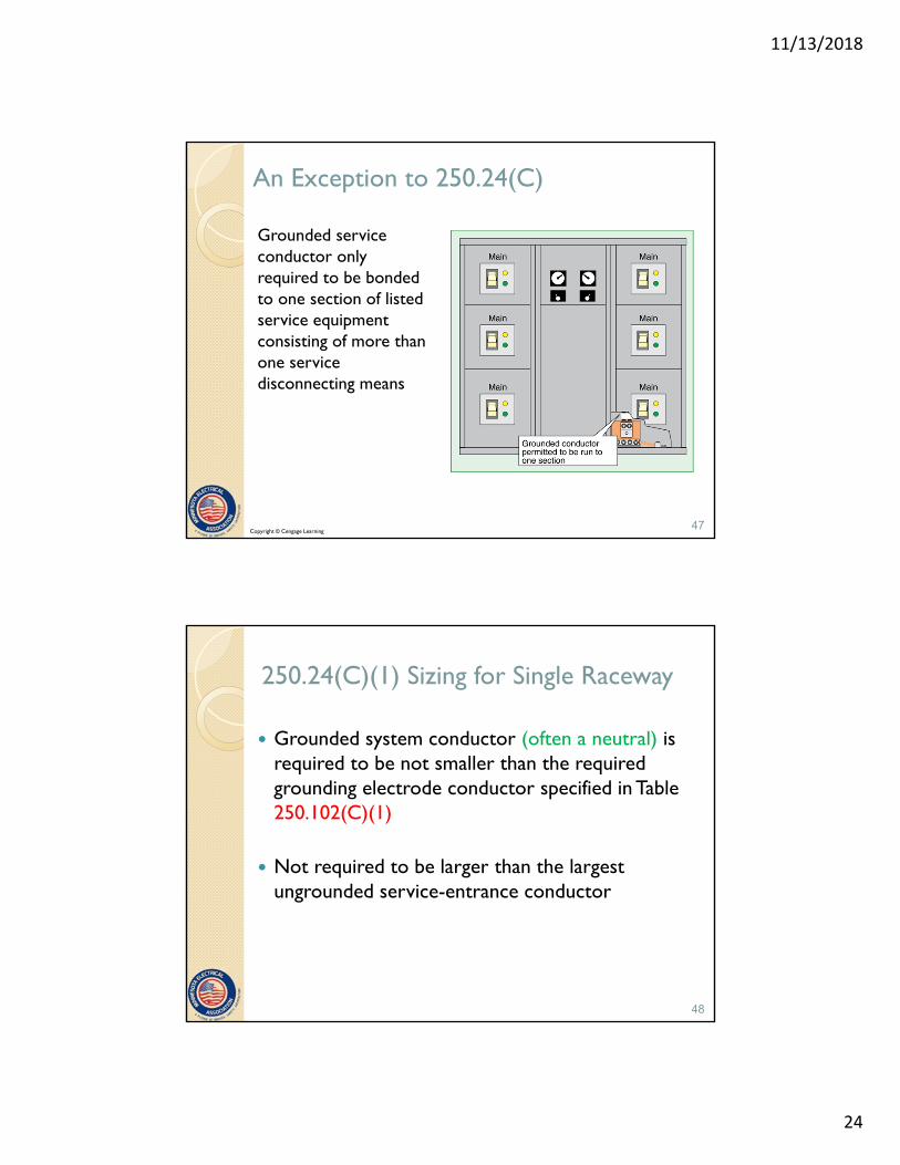
An Exception to 250.24(C)
Grounded service conductor only required to be bonded to one section of listed service equipment consisting of more than one service disconnecting means
47Copyright © Cengage Learning
250.24(C)(1) Sizing for Single Raceway
Grounded system conductor (often a neutral) is required to be not smaller than the required grounding electrode conductor specified in Table 250.102(C)(1)
Not required to be larger than the largest ungrounded service-entrance conductor
48

11/13/2018
25
250.24(C)(1) Sizing for Single Raceway
• Obtain size of service-entrance conductors
• Use the size of these conductors in Table 250.102(C)(1) to determine the minimum size of the grounded system conductor
• Compare to the size of grounded conductor required from load calculation in 220.61
• Compare to instructions from design engineer
• Install the largest of these conductors
49
250.24(C)(1) Sizing for Single Raceway
For parallel sets of conductors installed in compliance with 310.10(H):◦ If in one raceway such as a wireway, determine the area
of the largest set of conductors in parallel and consider as one conductor
◦ Follow Table 250.102(C)(1) for size of neutral conductor
◦ If area of ungrounded set of conductors is larger than 1100 kcm copper then
◦ Table 250.102(C)(1), apply 12.5% rule
50

11/13/2018
26
250.24(C)(2 ) Sizing for Parallel runs in two or more raceways
The grounded conductor shall also be installed in parallel. The size of the grounded in each raceway, or cable, shall be based on the total CM area of the parallel ungrounded conductors in the raceway, or cable, but not smaller than 1/0 AWG
Copyright © Cengage Learning

11/13/2018
27
Example
350 kcmil aluminum service lateral conductors in each conduit
◦ Table 250.102(C)(1) = 2 AWG copper or 1/0 aluminum
◦ Compare to size required by load calculation
◦ Minimum 1/0 AWG for parallel grounded conductor installations
◦ Install largest required conductor
53
Example
3/0 AWG copper conductors to 200 ampere service disconnect
◦ Table 250.102(C)(1) requires 4 AWG copper or #2 AWG aluminum grounded conductor
◦ Larger conductor may be required by load calculation
54

11/13/2018
28
More Requirements
For service-entrance conductors larger than 1100 kcmil copper or 1750 kcmil aluminum, the grounded system conductor must be not smaller than 12½ percent of the area of the largest service-entrance phase conductor
This presumes all service conductors are in a single raceway such as a wireway
55
56Copyright © Cengage Learning

11/13/2018
29
Example
Add together the circular mil area of the largest set of service-entrance conductors
Multiply this value by 0.125 (12½ percent) The result is the minimum size of grounded
(neutral) conductor
Go to Table 8 of Chapter 9
57
Example
Table 250.102(C)(1) can be used for conductor sizes covered by the table
◦ 800 ampere service with 2 sets of 500 kcmil service conductors
◦ 500 kcmil × 2 = 1000 kcmil
◦ Table 250.102(C)(1) requires 2/0 AWG copper main bonding, or system bonding conductor
58
11/13/2018
30
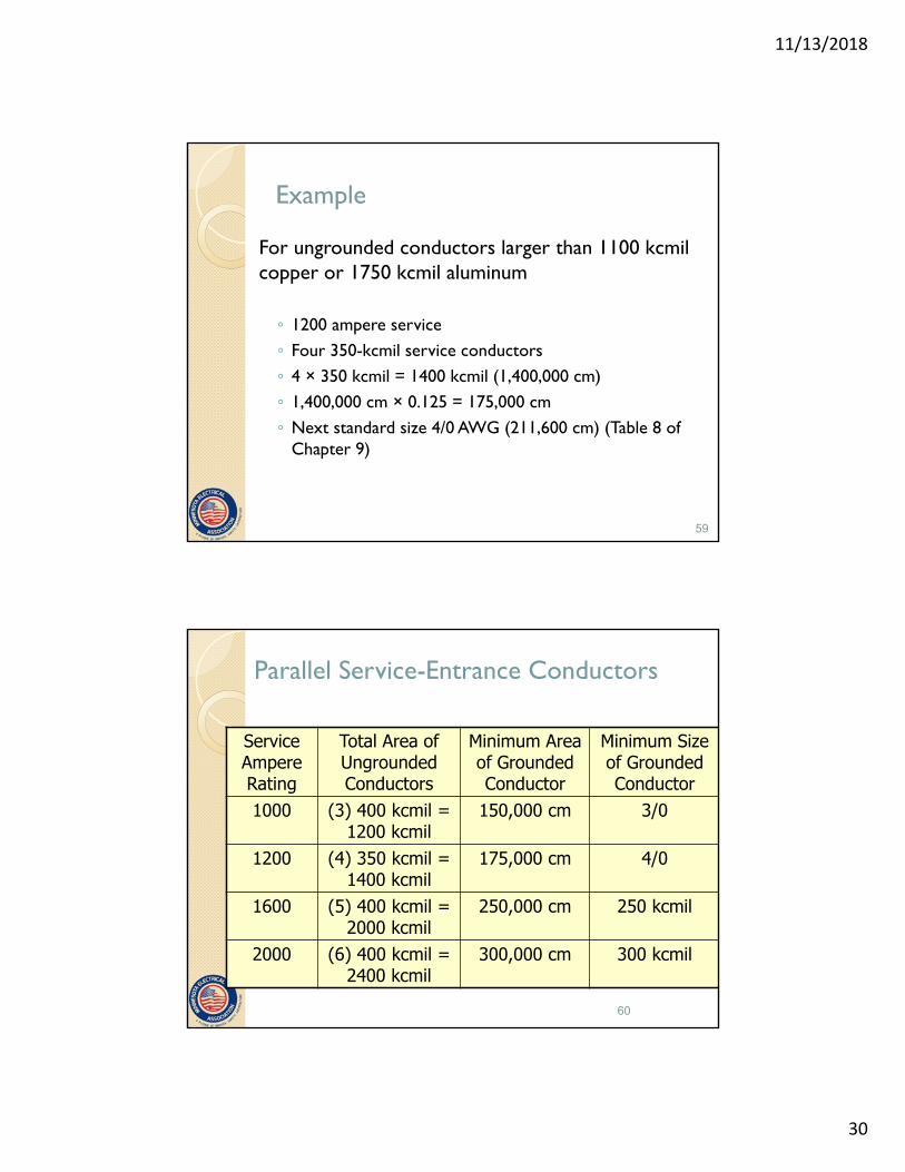
Example
For ungrounded conductors larger than 1100 kcmilcopper or 1750 kcmil aluminum
◦ 1200 ampere service
◦ Four 350-kcmil service conductors
◦ 4 × 350 kcmil = 1400 kcmil (1,400,000 cm)
◦ 1,400,000 cm × 0.125 = 175,000 cm
◦ Next standard size 4/0 AWG (211,600 cm) (Table 8 of Chapter 9)
59
Parallel Service-Entrance Conductors
Service Ampere Rating
Total Area of Ungrounded Conductors
Minimum Area of Grounded Conductor
Minimum Size of Grounded Conductor
1000 (3) 400 kcmil = 1200 kcmil
150,000 cm 3/0
1200 (4) 350 kcmil = 1400 kcmil
175,000 cm 4/0
1600 (5) 400 kcmil = 2000 kcmil
250,000 cm 250 kcmil
2000 (6) 400 kcmil = 2400 kcmil
300,000 cm 300 kcmil
60

11/13/2018
31
250.24(C)(2) Parallel Conductors
Applies where two or more raceways are installed
Grounded conductor in each raceway sized on the circular mil area of the ungrounded conductor in the raceway
Minimum size 1/0 AWG
Table 250.102(C)(1) used for sizing, or calculated load whichever is larger
61
Copyright © Cengage Learning
11/13/2018
32
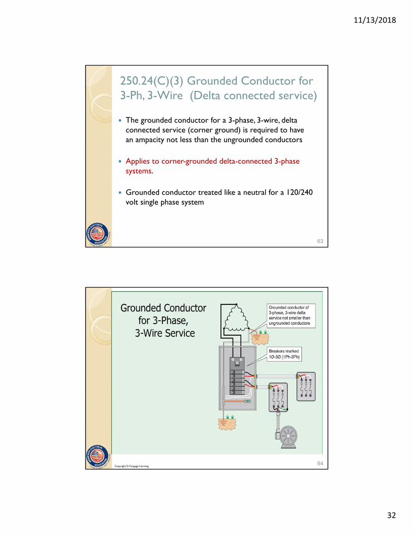
250.24(C)(3) Grounded Conductor for 3-Ph, 3-Wire (Delta connected service)
The grounded conductor for a 3-phase, 3-wire, delta connected service (corner ground) is required to have an ampacity not less than the ungrounded conductors
Applies to corner-grounded delta-connected 3-phase systems.
Grounded conductor treated like a neutral for a 120/240 volt single phase system
63
64Copyright © Cengage Learning
11/13/2018
33
250.24(D) Grounding Electrode Conductor
A grounding electrode conductor is required to be used to connect the equipment grounding conductors, the service-equipment enclosures and, where the system is grounded, the grounded service conductor to the grounding electrode(s) required by Part III of Article 250.
Size conductor per 260.66 (both the written article and the table)
High-impedance grounded neutral system connections are grounded in accordance with 250.36
65
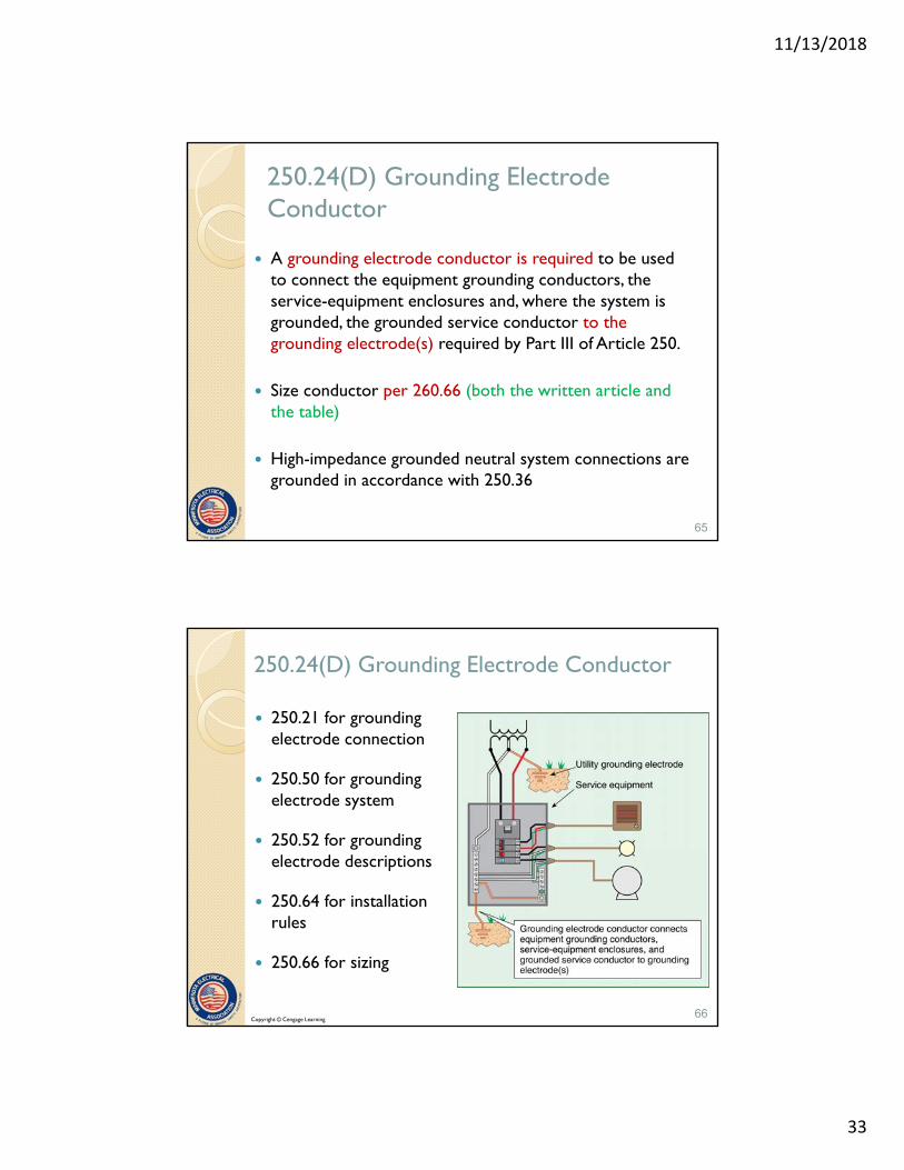
250.24(D) Grounding Electrode Conductor
250.21 for grounding electrode connection
250.50 for grounding electrode system
250.52 for grounding electrode descriptions
250.64 for installation rules
250.66 for sizing
66Copyright © Cengage Learning
11/13/2018
34
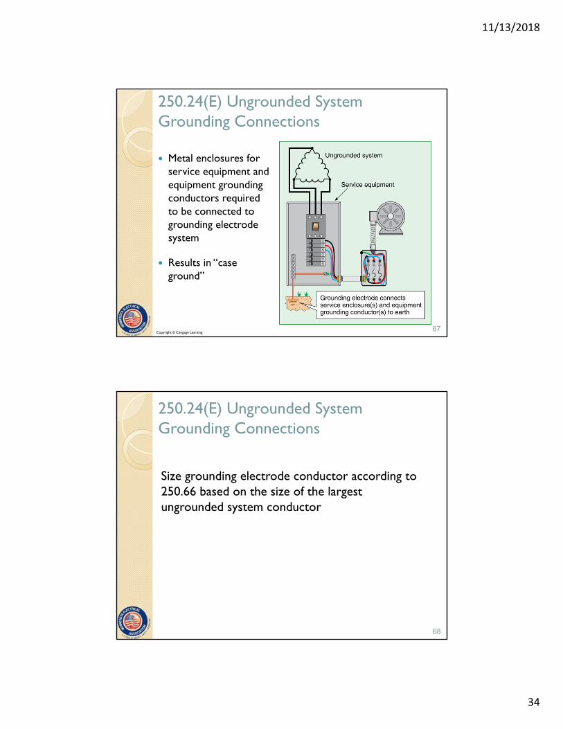
250.24(E) Ungrounded System Grounding Connections
Metal enclosures for service equipment and equipment grounding conductors required to be connected to grounding electrode system
Results in “case ground”
67Copyright © Cengage Learning
250.24(E) Ungrounded System Grounding Connections
Size grounding electrode conductor according to 250.66 based on the size of the largest ungrounded system conductor
68

11/13/2018
35
250.26 Conductor to be Grounded –AC Systems
1. Single-phase, 2-wire –one conductor
Typically 120-volt systems
69Copyright © Cengage Learning
250.26 Conductor to be Grounded –AC Systems
2. Single-phase, 3-wire –the neutral conductor
Typically 120/240 volt, 1-phase, 3-wire
70Copyright © Cengage Learning
11/13/2018
36
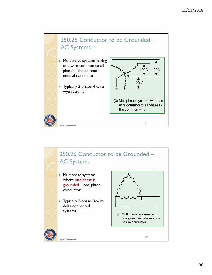
250.26 Conductor to be Grounded –AC Systems
3. Multiphase systems having one wire common to all phases - the common neutral conductor
Typically 3-phase, 4-wire wye systems
71Copyright © Cengage Learning
250.26 Conductor to be Grounded –AC Systems
4. Multiphase systems where one phase is grounded – one phase conductor
Typically 3-phase, 3-wire delta connected systems
72Copyright © Cengage Learning

11/13/2018
37
250.26 Conductor to be Grounded –AC Systems
5. Multiphase systems in which one phase is used as in (2) Single phase –the neutral conductor
Typically 120/240 volt, 3-phase, 4-wire systems
73Copyright © Cengage Learning
250.28 Main and System Bonding Jumpers The main bonding jumper
shall be copper or other corrosion resistant material- a wire, bus, (green) screw, or….
Sized as per 250.28(D) 1-3
Main bonding jumpers are installed at the service
System bonding jumpers are installed at separately derived systems
Perform identical functions
74Copyright © Cengage Learning

11/13/2018
38
250.28(A) Material
Permitted to be of copper or other corrosion-resistant material
Permitted to consist of a wire, bus, screw or similar suitable conductor
75Copyright © Cengage Learning
Main Bonding Jumper in Listed Equipment
Category UL Product Category
Panelboards UL 67, Panelboards
Switchboards UL 891, Dead-front Switchboards
Power Outlets UL 231, Power Outlets
Motor Control UL 845, Electric Motor Control Centers
Enclosed Switches UL 98, Enclosed Switches
76

11/13/2018
39
Suitable Only for Use as Service Equipment
Neutral terminal bar bonded to the enclosure
Typically, not permitted at the “feeder” position
May be acceptable at disconnecting means for separately derived system
See UL White book at: ul.com/whitebook(NJAV) and (WEVZ)
77Copyright © Cengage Learning
250.28(B) Construction
Where a main bonding jumper is a screw only, it is required to have a green finish that is visible with the screw installed
78Copyright © Cengage Learning
11/13/2018
40
250.28(C) Attachment
Attach main bonding jumpers in compliance with the general rules for making grounding and bonding connections as provided in 250.8
79
250.28(D)(1) Size of main or system bonding jumpers
(1) Main bonding jumpers and system bonding jumpers -Generally, not smaller than given in Table 250.102C1
For supply conductors larger than 1100 kcmilcopper or 1750 kcmil aluminum, size not smaller than 12½ percent of the area of the largest phase conductor
The bonding jumper in listed service equipment can be used without calculation
80

11/13/2018
41
250.28(D)(2) Main Bonding Jumper for Service with More than One Enclosure
If the service consists of more than a single enclosure as permitted in 230.71(A), the main bonding jumper for each enclosure is required to be sized in accordance with 250.28(D)(1) based upon the largest ungrounded service conductor serving that enclosure
Manufacturer-provided main bonding jumper for listed equipment can be installed without calculation
81
250.28(D)(3) Separately Derived System with More Than One Enclosure
If a separately derived system supplies more than one enclosure, the system bonding jumper must be installed at either the source of the separate system, or first system disconnecting means
If at the first disconnecting means, use main bonding jumper supplied for listed enclosure or size according to 250.28(D)(1)
If at the source, size system bonding jumper per 250.28(D)(1) based on the sum of circular mil area of derived ungrounded conductors for one phase
82

11/13/2018
42
Example: More than one enclosure
Feeder Derived Conductors
Number Per Phase
Circular Mil Area
400 Ampere 600 kcmil 1 600 kcmil
600 Ampere 350 kcmil 2 700 kcmil
Total area 1300 kcmil
System Bonding Jumper 12½ Percent of 1300 kcmil 162,500 cm
83
( 3/0)
84Copyright © Cengage Learning

11/13/2018
43
250.30 Grounding Separately Derived Systems
Definition of term in Article 100 To comply with 250.30(A) for grounded systems,
or as provided in 250.30(B) for ungrounded systems
Separately derived systems shall comply with 250.20, 250.21, 250.22, and 250.26
Multiple separately derived systems that are connected in parallel shall be installed in accordance with 250.30.
85
Article 100 definition: Separately Derived Systems
“An electrical source, other than a service, having no direct connection(s) to circuit conductors of any other electrical source other than those established by grounding and bonding connections.”
86
11/13/2018
44
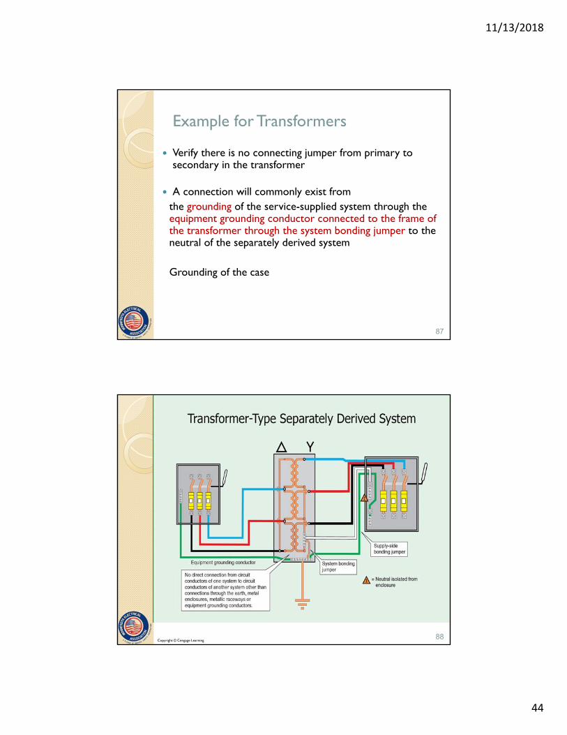
Example for Transformers
Verify there is no connecting jumper from primary to secondary in the transformer
A connection will commonly exist from the grounding of the service-supplied system through the equipment grounding conductor connected to the frame of the transformer through the system bonding jumper to the neutral of the separately derived system
Grounding of the case
87
88Copyright © Cengage Learning

11/13/2018
45
Strap bonds core to the case. NOT the system bonding jumper.
89
Here’s How for Generators
Look in the transfer switch
If the neutral is switched, the system supplied is separately derived
If the neutral is not switched, the system supplied is not separately derived
90

11/13/2018
46
91Copyright © Cengage Learning
Autotransformers
Autotransformer has a conductor that is common to both primary and secondary
Cannot be a separately derived system
92Copyright © Cengage Learning
11/13/2018
47
250.30(A) Grounded Systems
A separately derived system that is grounded must comply with the rules in (A)(1) - (A)(8)
A grounding to grounded connection is not generally permitted on the load side of the grounding point of the separately derived system
Load-side grounding permitted under specific rules in 250.32 and 250.142
93
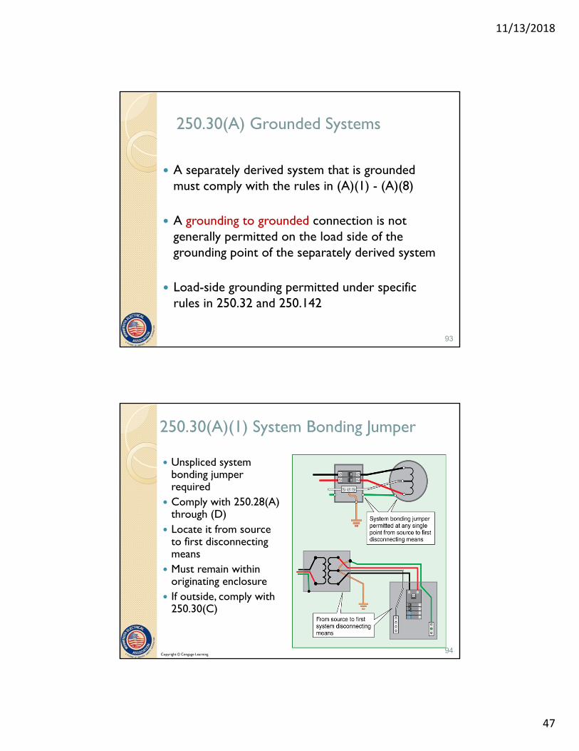
250.30(A)(1) System Bonding Jumper
Unspliced system bonding jumper required
Comply with 250.28(A) through (D)
Locate it from source to first disconnecting means
Must remain within originating enclosure
If outside, comply with 250.30(C)
94Copyright © Cengage Learning

11/13/2018
48
250.30(A)(1) Size of System Bonding Jumper
Size system bonding jumper based on size of ungrounded derived conductors Table 250.102(C)(1)
If Bonding jumper is furnished with listed service equipment -permitted without calculation of size
95Copyright © Cengage Learning
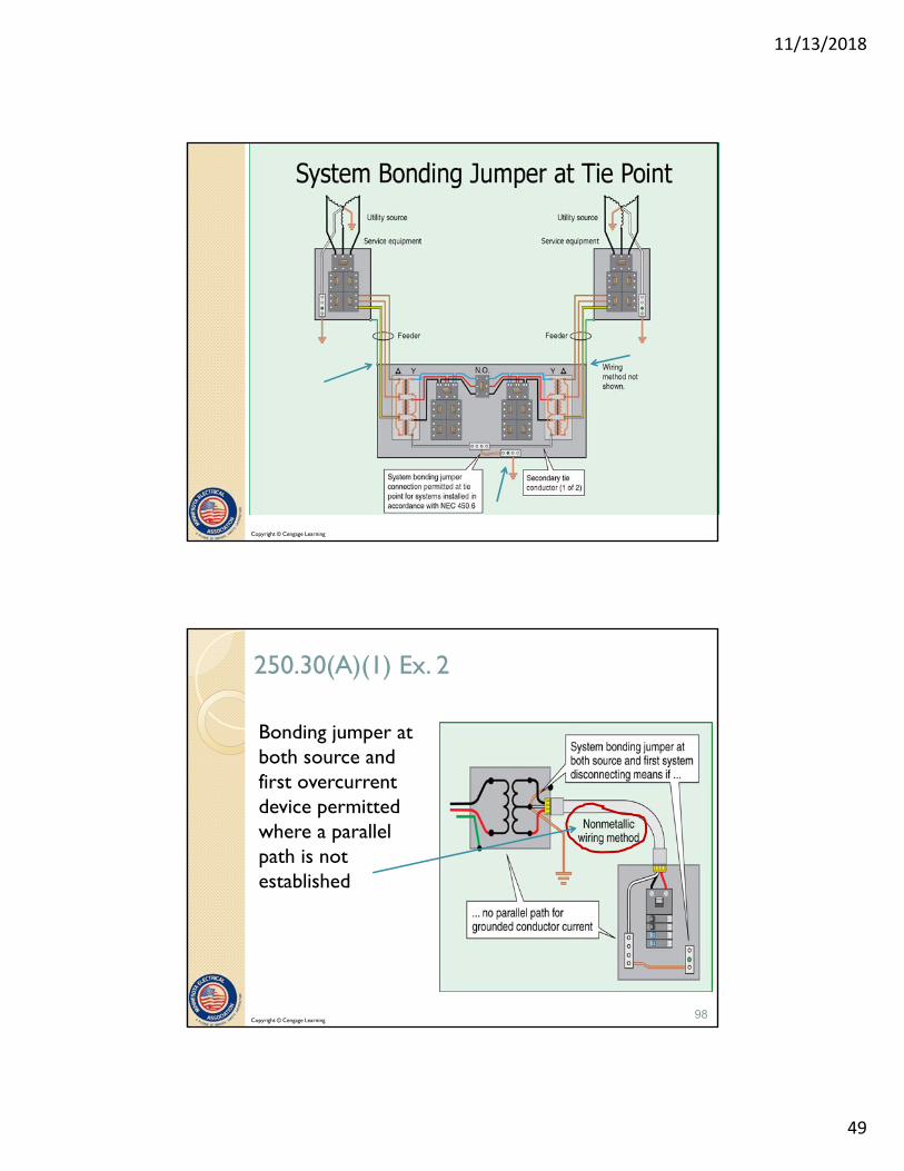
250.30(A)(1) Ex. No. 1
A single system bonding jumper connection at the tie point is permitted for systems installed in accordance with 450.6 (secondary tie points)
This equipment is commonly double-ended equipment supplied from two separately derived systems.
The neutral of the two systems is tied together by this connection
96
11/13/2018
49
97Copyright © Cengage Learning
250.30(A)(1) Ex. 2
Bonding jumper at both source and first overcurrent device permitted where a parallel path is not established
98Copyright © Cengage Learning

11/13/2018
50
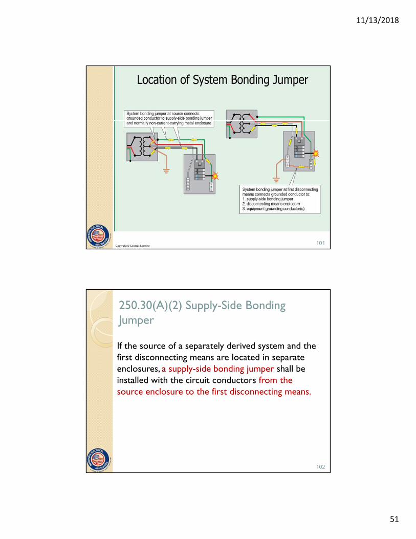
250.30(A)(1)(a) System Bonding Jumper at Source
The system bonding jumper is required to connect the grounded conductor to the supply-side bonding jumper and the normally non–current-carrying metal enclosure.
99
250.30(A)(1)(b) System Bonding Jumper at First Disconnecting Means
The system bonding jumper is required to connect the grounded conductor to the supply-side bonding jumper, the disconnecting means enclosure, and the equipment grounding conductor(s).
100
11/13/2018
51
Copyright © Cengage Learning101
250.30(A)(2) Supply-Side Bonding Jumper
If the source of a separately derived system and the first disconnecting means are located in separate enclosures, a supply-side bonding jumper shall be installed with the circuit conductors from the source enclosure to the first disconnecting means.
102

11/13/2018
52
250.30(A)(2) Supply-Side Bonding Jumper
A supply-side bonding jumper shall not be required to be larger than the derived ungrounded conductors.
103
250.30(A)(2) Supply-Side Bonding Jumper
The supply side bonding jumper shall be permitted to be of –nonflexible- metal raceway type or of the wire or bus type as follows:
(a) A supply-side bonding jumper of the wire type shall comply with 250.102(C), based on the size of the derived ungrounded conductors.
104

11/13/2018
53
250.30(A)(2) Supply-Side Bonding Jumper
(b) A supply-side bonding jumper of the bus type shall have a cross-sectional area not smaller than a supply-side bonding jumper of the wire type as determined in 250.102(C).
Exception: A supply-side bonding jumper shall not be required between enclosures for installations made in compliance with 250.30(A)(1), Exception No. 2.
105
106
Copyright © Cengage Learning106

11/13/2018
54
Table 2-3
Wiring Method Size Max OCP Length NEC
Reference
FMC All 20 A 6 ft (1.8 m)
250.118 (5)
LFMC 3/8 & ½ 20 A 6 ft (1.8 m)
250.118 (6)
LFMC ¾ thru 1¼ 60 A 6 ft
(1.8 m)250.118
(6)
LFMC Larger than 1¼
Not permitted
Not permitted
250.118 (6)
107
108
Copyright © Cengage Learning108

11/13/2018
55
Copyright © Cengage Learning109
250.30(A)(3) Grounded Conductor
(A)(3)(a) Rules identical to sizing grounded conductor for service◦ Ensures conductor is adequate for carrying fault current
◦ Also, size for calculated load
(A)(3)(b) Rules identical to sizing grounded conductors for services when installed in parallel
Table 250.102C1
110

11/13/2018
56
Copyright © Cengage Learning111
250.30(A)(4) Grounding Electrode
The building or structure grounding electrode system shall be used as the grounding electrode for a separately derived system. If located outdoors, the grounding electrode shall be in accordance with 250.30 (C) (Outdoor Source)
* Exception: If the SDS originates in equipment that is listed and identified for use as service equipment, the grounding electrode used for the service is permitted to be used as the GE for the SDS
112

11/13/2018
57
250.30(A)(4) Grounding Electrode
Primary purpose is bonding electrical structures or equipment that is likely to become energized
Rules for water pipe electrode apply
Rules for structural metal also apply
Building or structure grounding permitted
Copyright © Cengage Learning113
250.30(A)(4) GEC, Single Separately Derived System
Connect grounded conductor of separately derived system to grounding electrode
Connect at same point where system bonding jumper is connected
Copyright © Cengage Learning114
11/13/2018
58
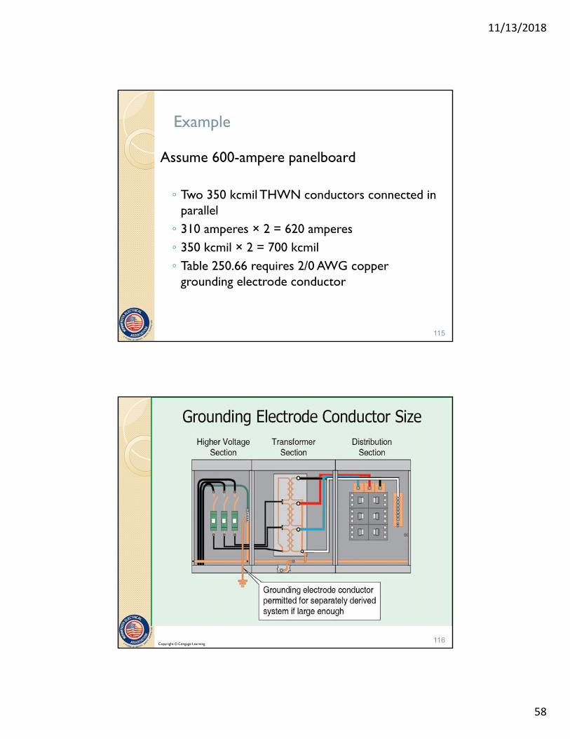
Example
Assume 600-ampere panelboard
◦ Two 350 kcmil THWN conductors connected in parallel◦ 310 amperes × 2 = 620 amperes◦ 350 kcmil × 2 = 700 kcmil◦ Table 250.66 requires 2/0 AWG copper
grounding electrode conductor
115
Copyright © Cengage Learning116
11/13/2018
59
Example
Determine the minimum size of the grounding electrode conductor for the derived system.
Determine the size of equipment grounding bus and grounding electrode conductor for the primary section.
Verify conductors are appropriate for grounding electrode conductor.
117
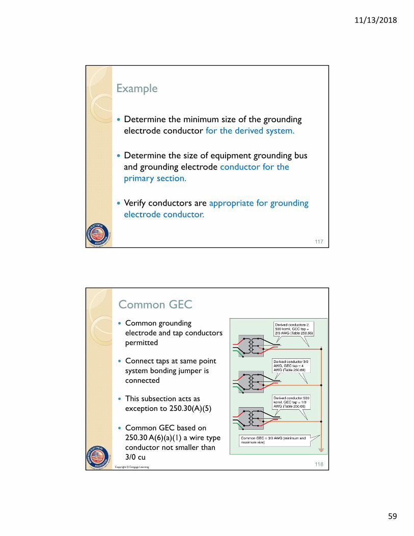
Common GEC Common grounding
electrode and tap conductors permitted
Connect taps at same point system bonding jumper is connected
This subsection acts as exception to 250.30(A)(5)
Common GEC based on 250.30 A(6)(a)(1) a wire type conductor not smaller than 3/0 cu
Copyright © Cengage Learning118

11/13/2018
60
250.30(A)(6)(a) Size of Common and Tap Grounding Electrode Conductor
(1) Minimum size permitted for common wire type GEC is 3/0 copper or 250 kcmil aluminum (Also is the maximum size required by this section)
Size tap conductors from 250.66 based upon the size of the derived ungrounded conductors
(2) A metal water pipe that complies with 250.68 (C)(1) The metal water piping system is allowed to serve as a grounding electrode if connected within 5 ft of the entrance * with exceptions
119
250.30(A)(6)(b) Tap Conductor size
Each tap conductor from the SDS to the Common GEC is sized as per 250.66 based on the derived ungrounded conductors
* See exceptions for service rated equipment
120

11/13/2018
61
250.30(A)(6)(c) Connections
Copyright © Cengage Learning121
250.30(A)(6)(c) Connections
¼” thick, 2” wide, Sufficient length for terminations
Copyright © Cengage Learning122

11/13/2018
62
250.30(A)(7) Installation (8) Bonding
(7) Comply with 250.64(A), (B), (C) and (E)◦ (A) Aluminum conductors
◦ (B) Installation rules
◦ (C) Unbroken unless installed in compliance with rules
◦ (E) Bonding of ferrous metal raceways that enclose grounding electrode conductor
(8) Structural steel and metal pipes shall be connected to the grounded conductor of a SDS
123
250.30(B) Ungrounded Systems
1. Grounding electrode conductor based on size of ungrounded derived conductor
2. Except for portable and vehicle-mounted generators, the grounding electrode is required to comply with 250.30(A)(4)
3. Install supply-side bonding jumper between the source of the separately derived system and the first disconnecting means in compliance with 250.30(A)(2)
124

11/13/2018
63
Copyright © Cengage Learning125
250.30(C) Outdoors Source
If the source of the separately derived system is located outside the building or structure supplied, a grounding electrode connection shall be made at the source location to one or more grounding electrodes in compliance with 250.50. In addition, the installation shall comply with 250.30(A) for grounded systems or with 250.30(B) for ungrounded systems. (previous slides)
This rule requires the system bonding jumper to also be located at the outdoor source.
* See exception for impedance grounded systems
126

11/13/2018
64
Copyright © Cengage Learning127
Copyright © Cengage Learning128

11/13/2018
65
Copyright © Cengage Learning129
Copyright © Cengage Learning130

11/13/2018
66
250.32 Buildings or Structures Supplied by a Feeder(s) or Branch Circuit(s)
Bond all grounding electrodes, installed as per Part III of Art 250, together at building or structure to form grounding electrode system
Connect at building disconnecting means in accordance with 250.32(B) or (C) (following)
Install grounding electrode(s) if none exist See 250.52(A) for description of grounding electrodes
required to be used
* See exception for a building with only one branch circuit.
131
250.32 Buildings or Structures Supplied by a Feeder(s) or Branch Circuit(s)
(A) Bond all grounding electrodes together to form grounding electrode system
Connect in accordance with 250.32(B) or (C)
If no grounding electrodes, install per 250.50
Copyright © Cengage Learning132
11/13/2018
67
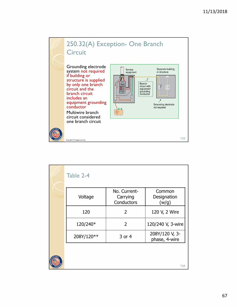
250.32(A) Exception- One Branch Circuit
Grounding electrode system not required if building or structure is supplied by only one branch circuit and the branch circuit includes an equipment grounding conductorMultiwire branch circuit considered one branch circuit
Copyright © Cengage Learning133
Table 2-4
VoltageNo. Current-
Carrying Conductors
Common Designation
(w/g)
120 2 120 V, 2 Wire
120/240* 2 120/240 V, 3-wire
208Y/120** 3 or 4 208Y/120 V, 3-phase, 4-wire
*Considered a multiwire branch circuit** See 310.15(B)(5) for the rules on when a neutral is
considered a current-carrying conductor
134

11/13/2018
68
250.32(B)(1) Grounded Systems Supplied by a feeder or branch circuit
Connection of grounding electrode at building or structure disconnecting means must be to equipment grounding conductor terminal bar or metal enclosure for disconnecting means
* Exception: Connecting neutral conductor to enclosure or grounding electrode is now limited to existing buildings or structures
Isolate the neutral conductor at the remote building or structure. Do not connect to grounding electrode
135
Copyright © Cengage Learning136

11/13/2018
69
250.32(B)(1) Exception: Grounded Systems
Applies to installations made in compliance with previous editions of the NEC that permitted such connection.
Grounded conductor run with the supply to the building or structure disconnecting means is permitted to serve as ground-fault return path if all conditions continue to be met.
137
Neutral to grounding electrode
Copyright © Cengage Learning138

11/13/2018
70
250.32(B)(2) Supplied by Separately Derived System (SDS)
(a) With Overcurrent Protection. If overcurrent protection is provided where the conductors originate, the installation shall comply with 250.32(B)(1). (previous slides)
The general rules require an equipment grounding conductor be installed with the feeder or branch circuit to serve as the ground-fault return path.
The equipment grounding conductor connects to the building or structure disconnecting means and to the grounding electrode.
139
250.32(B)(2) Supplied by Separately Derived System
(b) Without Overcurrent Protection. If overcurrent protection is not provided where the conductors originate, the installation shall comply with 250.30(A). If installed, the supply-side bonding jumper shall be connected to the building or structure disconnecting means and to the grounding electrode(s).
In addition to these rules for grounding or bonding, the requirements for overcurrent protection in 240.21(C) must be complied with.
140

11/13/2018
71
250.32(C) Ungrounded Systems supplied by feeders or branch circuits to separate buildings
(C)(1) Supplied by a Feeder or Branch Circuit
(C)(2) Supplied by a Separately Derived System
141
250.32(C)(1) Ungrounded Systems
Install equipment grounding conductor
Connect the grounding electrode conductor to the disconnecting means
Copyright © Cengage Learning142

11/13/2018
72
250.32(C)(2) Ungrounded Systems Supplied by Separately Derived System
(a) Ungrounded With Overcurrent Protection. If overcurrent protection is provided where the conductors originate, the installation shall comply with 250.32(B)(1).
143
Copyright © Cengage Learning144

11/13/2018
73
250.32(C)(2) Ungrounded Systems Supplied by Separately Derived System
(b) Ungrounded Without Overcurrent Protection. If overcurrent protection is not provided where the conductors originate, - the installation shall comply with 250.30(A).
If installed, the supply-side bonding jumper shall be connected to the building or structure disconnecting means and to the grounding electrode(s).
145
Copyright © Cengage Learning146

11/13/2018
74
250.32(E) Grounding Electrode Conductor
Size from 250.66 based on size of feeder or branch circuit conductor that supplies a building or structure
Copyright © Cengage Learning147
250.34 Portable and Vehicle-Mounted Generators
The frame is not required to be connected to a grounding electrode if:
1. The generator supplies only equipment mounted on the generator
2. Non-current-carrying parts are bonded to the frame
148

11/13/2018
75
Copyright © Cengage Learning149
Connection of Portable or Vehicle-Mounted Generator
Break to avoid parallel path
Or do not bond here to avoid parallel path
Copyright © Cengage Learning150

11/13/2018
76
Violates switched neutral rule for generator connection
Copyright © Cengage Learning151
250.34(B) Vehicle-Mounted Generators (no grounding electrode required)
Not required to be connected to grounding electrode if:1. Frame of generator
bonded to frame of vehicle
2. Equipment supplied by cord-and-plug connection
3. Non-current-carrying parts connected to frame
Copyright © Cengage Learning152

11/13/2018
77
250.34(C) Grounded Conductor Bonding
A system conductor that is required to be grounded by 250.26 must be bonded to the generator frame where the generator is a component of a separately derived system
Provides path for ground-fault current to return to the source (generator)
See 250.30 for portable generators supplying fixed wiring systems
153
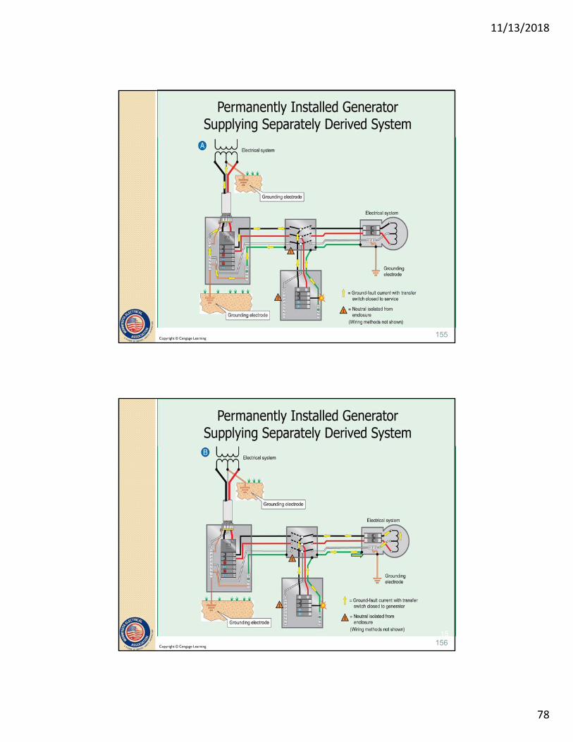
250.35, Permanently Installed Generators
A conductor that provides an effective ground-fault current path is required to be installed with the supply conductors from a permanently installed generator(s) to the first disconnecting means in accordance with (A) or (B). (below)
A. If the generator is a component of a separately derived system, comply with 250.30
154
11/13/2018
78
Copyright © Cengage Learning155
156
Copyright © Cengage Learning156

11/13/2018
79
250.35, Permanently Installed Generators
(B) Non-Separately Derived System. If the generator is not installed as a separately derived system, a supply-side bonding jumper must be installed between the generator equipment grounding terminal and the equipment grounding terminal, bar or busSize according to 250.102(C 1) based on the size of conductors supplied by generator
157
Not Separately Derived system
Normal service conditions
Copyright © Cengage Learning158

11/13/2018
80
Not separately derived system
Generator supply conditions
Copyright © Cengage Learning159
Example:
800 ampere overcurrent device with 2 600kcmil copper conductors in parallel from generator to distribution panelboard
Line side: Size bonding jumper in each raceway based on Table 250.102(C)(1) = 1/0 CU or 3/0 AL
160

11/13/2018
81
250.36 High-Impedance Grounded Neutral Systems
Permitted where:
1. Qualified persons service the installation
2. Ground detectors are installed
3. Line-to neutral loads are not served
Copyright © Cengage Learning161
250.36(A) Grounding Impedance Location
Grounding impedance installed between grounding electrode and the system neutral
If the neutral point is not available, the grounding impedance shall be installed between the grounding electrode conductor and the neutral point derived from a grounding transformer
Provides “controlled” path for neutral current to return to the source
Limits current from first ground fault to the value of the impedance device
162

11/13/2018
82
250.36(B) Grounded Conductor
Must be fully insulated to maintain “controlled” return path
Minimum size not less than maximum current rating of impedance device and shall in no case be smaller than #8 AWG copper or #6 AWG aluminum
163
250.36(C) System Grounding Connection
System neutral conductor is not permitted to be connected to ground except through the grounding impedance
Provides “controlled” return path
Copyright © Cengage Learning164

11/13/2018
83
250.36(D) Conductor Routing
The conductor that connects the neutral point of the transformer to the grounding impedance is:
Permitted to be installed in separate raceway from phase conductors
Impedance devices are typically located in a separate enclosure adjacent to distribution equipment
165
250.36(E) Equipment Bonding Jumper
Equipment bonding jumper to be an unspliced conductor
Run from first disconnecting means to grounded side of grounding impedance
Copyright © Cengage Learning166

11/13/2018
84
250.36(G) Equipment Bonding Jumper Size
1. If the grounding electrode connection is made at the grounding impedance, the equipment grounding jumper is sized per 250.66 based on the size of the service-entrance conductors or derived conductors
2. If connected at first system disconnecting means, sized the same as the neutral conductor in 250.36(B) (As above)
167
Connection point of grounding Electrode Conductor
Copyright © Cengage Learning168

11/13/2018
85
The End - Part 2
Questions?
169