me6604 gas dynamics and jet propulsion l t p c 3 0 0 3 ... · me6604 gas dynamics and jet...
TRANSCRIPT
REGULATION : 2013 ACADEMIC YEAR : 2018-19
JIT-JEPPIAAR/MECH/Dr.S.BOOPATHI/IIIrd Yr/SEM 05/ME6604/GAS DYNAMICS AND JET PROPULSION/UNIT 1-5/QB+Keys/Ver1.0
5-1
ME6604 GAS DYNAMICS AND JET PROPULSION L T P C
3 0 0 3
OBJECTIVES:
• To understand the basic difference between incompressible and compressible flow.
• To understand the phenomenon of shock waves and its effect on flow. To gain some basic knowledge
about jet propulsion and Rocket Propulsion.
(Use of Standard Gas Tables permitted)
UNIT I BASIC CONCEPTS AND ISENTROPIC FLOWS 6
Energy and momentum equations of compressible fluid flows – Stagnation states, Mach waves and Mach
cone – Effect of Mach number on compressibility – Isentropic flow through variable ducts – Nozzle and
Diffusers
UNIT II FLOW THROUGH DUCTS 9
Flows through constant area ducts with heat transfer (Rayleigh flow) and Friction (Fanno flow) – variation
of flow properties.
UNIT III NORMAL AND OBLIQUE SHOCKS 10
Governing equations – Variation of flow parameters across the normal and oblique shocks – Prandtl –
Meyer relations – Applications.
UNIT IV JET PROPULSION 10
Theory of jet propulsion – Thrust equation – Thrust power and propulsive efficiency – Operating
principle, cycle analysis and use of stagnation state performance of ram jet, turbojet, turbofan and turbo
prop engines.
UNIT V SPACE PROPULSION 10
Types of rocket engines – Propellants-feeding systems – Ignition and combustion – Theory of rocket
propulsion – Performance study – Staging – Terminal and characteristic velocity – Applications – space
flights.
TOTAL: 45 PERIODS
OUTCOMES:
Upon completion of this course, the students can able to successfully apply gas dynamics principles in
the Jet and Space Propulsion
REGULATION : 2013 ACADEMIC YEAR : 2018-19
JIT-JEPPIAAR/MECH/Dr.S.BOOPATHI/IIIrd Yr/SEM 05/ME6604/GAS DYNAMICS AND JET PROPULSION/UNIT 1-5/QB+Keys/Ver1.0
5-2
TEXT BOOKS:
1. Anderson, J.D., "Modern Compressible flow", 3rd Edition, McGraw Hill, 2003.
2. Yahya, S.M. "Fundamentals of Compressible Flow", New Age International (P) Limited, New Delhi,
1996.
REFERENCES:
1. Hill. P. and C. Peterson, "Mechanics and Thermodynamics of Propulsion", Addison – Wesley
Publishing company, 1992.
2. Zucrow. N.J., "Aircraft and Missile Propulsion", Vol.1 & II, John Wiley, 1975.
3. Zucrow. N.J., "Principles of Jet Propulsion and Gas Turbines", John Wiley, New York, 1970.
4. Sutton. G.P., "Rocket Propulsion Elements", John wiley, New York,1986,.
5. Shapiro. A.H.," Dynamics and Thermodynamics of Compressible fluid Flow", John wiley, New York,
1953.
6. Ganesan. V., "Gas Turbines", Tata McGraw Hill Publishing Co., New Delhi, 1999.
7. Somasundaram. PR.S.L., "Gas Dynamics and Jet Propulsions", New Age International Publishers,
1996.
8. Babu. V., "Fundamentals of Gas Dynamics", ANE Books India, 2008.
9. Cohen. H., G.E.C. Rogers and Saravanamutto, "Gas Turbine Theory", Longman Group Ltd., 1980.

REGULATION : 2013 ACADEMIC YEAR : 2018-19
JIT-JEPPIAAR/MECH/Dr.S.BOOPATHI/IIIrd Yr/SEM 05/ME6604/GAS DYNAMICS AND JET PROPULSION/UNIT 1-5/QB+Keys/Ver1.0
5-3
Subject Code : ME6604 Year/Semester : III/ 06
Subject Name : Gas Dynamics and Jet Propulsion Subject Handler : Dr. S. Boopathi
UNIT I BASIC CONCEPTS AND ISENTROPIC FLOWS
Energy and momentum equations of compressible fluid flows – Stagnation states, Mach waves and Mach
cone – Effect of Mach number on compressibility – Isentropic flow through variable ducts – Nozzle and
Diffusers
PART * A
Q.No. Questions
1. Write any two applications of nozzle and diffuser. (Nov/Dec 2015) BTL1
Aircraft (jet engines) and rocket applications.
2
"Higher the velocity of supersonic flow, smaller the angle of Mach cone" comment on the
validity of this statement. (Nov/Dec 2015) BTL4
Sin of Mach angle is equal to the reciprocal of Mach number, therefore the higher the velocity of
supersonic flow, smaller the angle of Mach cone.
3 What is meant by gas dynamics? (April/May 2015) BTL1
G s dynamics deals with the steady of motion of gasses and its effects.
4
Define Mach number. (April/May 2015) BTL1
The Mach number is an index of the ratio between the inertia force and elastic force or It is also
defined as the ratio of the fluid velocity (C or U) to the velocity of sound (a).
5
Find the maximum possible velocity in a medium of air when static temperature is 200ºC and
velocity is 120 m/s. (Nov/Dec 2014) BTL3
C max = 982.16 m/s.
6
When does the maximum mass flow occur for an isentropic flow with variable area and what
type of nozzle used for sonic flow and supersonic flow? (Nov/Dec 2014) BTL4
Mass flow rate will be maximum at throat section where Mach number is one. Constant area duct
nozzle is used for supersonic flow.
7
Distinguish between nozzle and diffuser. (May /June 2014) BTL4
Nozzle: varying cross sectional area through which pressure energy decreases and kinetic energy
increases. Diffuser: varying cross sectional area through which pressure energy increases and
kinetic energy decreases.
8 When does maximum flow occur for an isentropic flow with variable area duct? (May /June
2014) BTL3

REGULATION : 2013 ACADEMIC YEAR : 2018-19
JIT-JEPPIAAR/MECH/Dr.S.BOOPATHI/IIIrd Yr/SEM 05/ME6604/GAS DYNAMICS AND JET PROPULSION/UNIT 1-5/QB+Keys/Ver1.0
5-4
When the pack pressure ratio P/Po = (2/ν+1) power of (ν/ν-1) , mass flow rate will be maximum,
M=1 at throat section.
9
What are the basic difference between compressible and incompressible flows? (May /June
2013) BTL1
Compressible flow Density of the fluid changes from point to point, Incompressible density remains
constant.
10
Name the four reference velocities that are used in expressing the third velocities in non-
dimensional form. (May /June 2013) BTL1
Local velocity of sound (a), Stagnation velocity (ao), Maximum velocity of fluid Cmax, Critical
velocity of sound a* or c*.
11
Define Isentropic process. BTL1
An isentropic process is one in which there is no change in entropy. Such a process is a reversible
adiabatic process, for this process in the absence of shaft work, there is no change in eh stagnation
pressure and temperature.
P V = Constant
12
Define stagnation state. BTL1
The state of a fluid attained by isentropically decelerating it to zero velocity at zero elevation is
referred to as the stagnation state. Stagnation enthalpy h0 = h1 + ½ C2
13
Define stagnation temperature. BTL1
Stagnation temperature is the temperature of the gas when it is adiabatically decelerated to zero
velocity at zero elevation.
14
Define stagnation velocity of sound. BTL1
Stagnation velocity of sound is defined as the velocity of sound at stagnation temperature.
a0 = (r – 1 ) h0 = r R T0
15 Define Crocco Number. BTL1
It is defined as the ratio of fluid velocity to the maximum fluid velocity.
16
What is the effect of Mach number of compressibility? BTL1
In a compressible flow the value of pressure co-efficient deviates from unity and this deviation
increases with Mach number of the flow.
17 Relate the classification of flow based on Mach number value. BTL2
The classification of flow based on Mach number values are,
REGULATION : 2013 ACADEMIC YEAR : 2018-19
JIT-JEPPIAAR/MECH/Dr.S.BOOPATHI/IIIrd Yr/SEM 05/ME6604/GAS DYNAMICS AND JET PROPULSION/UNIT 1-5/QB+Keys/Ver1.0
5-5
M < < 1 Incompressible, M < 1 Sub Sonic , M 1 Transonic, M = 1 Sonic
M > 1 Supersonic, M > > 1 Hypersonic
18
Define Critical velocity of sound. BTL1
Critical velocity of sound is the velocity of fluid at unity Mach number.
C* = a* = r Rt*
19
Define Mach cone. BTL1
Mach cone is defined as the conical boundary obtained by drawing the tangent to the circles of sonic
wave fronts such that C > a is the velocity of fluid which is greater than velocity of sound.
20
Define Mach angle. BTL1
The angle between the Mach line and the direction of motion of the body is called Mach angle.
Sin = a/c = 1/M, where - Mach angle
Part B
1
An aircraft flies at a velocity of 700 kmph in an atmosphere where the pressure is 75 kPa and
temperature is 5 ºC. Calculate the Mach number and stagnation properties. (April/May 2015)
(13 M) BTL4
Answer: Page 1.76- Dr.S.Senthil
Air velocity C= 700 x103/3600 =194.44 m/s, P=75 x103 N/m2, T=278 K (4M)
a=√𝛾𝑅𝑇=334.22 m/s, (2M)
M=C/a = 0.58 (2M)
Refer isentropic flow table for 𝛾 = 1.4 𝑎𝑛𝑑 𝑀 = 0.58
T0=296.69 K, Stagnation pressure P0=0.942 x10⁵ N/m2 (2M)
Stagnation density = 1.106 kg/m3 (3M)
2
The pressure, temperature and velocity of air at the entry of a diffuser are 0.7 bar, 345 K and
190 m/s respectively. The entry diameter of a diffuser is 15 cm and exit diameter is 35 cm.
Determine the following: (i) Exit Pressure (ii) Exit velocity and (iii) Force exerted the diffuser
walls. Assuming isentropic flow and take ᵞ = 1.4, Cp=1005 J/kgK. (Apr 2018) (13 M) BTL5
Answer: Page 2.60- Dr.S.Senthil
Velocity of sound at inlet, a1=372.32 m/s
Mach number at inlet, M1= 0.51 (2M)
REGULATION : 2013 ACADEMIC YEAR : 2018-19
JIT-JEPPIAAR/MECH/Dr.S.BOOPATHI/IIIrd Yr/SEM 05/ME6604/GAS DYNAMICS AND JET PROPULSION/UNIT 1-5/QB+Keys/Ver1.0
5-6
From isentropic flow table for ᵞ=1.4 and M1=0.51
T01=362.78 K=T02, P01=0.836 bar=P02, A1*=0.01337=A2*, A2= 0.096 m2, (4M)
A2/A2*=7.180 convergent type diffuser
From Isentropic flow table A2/A2*=7.180 and ᵞ=1.4
P2=0.832 bar, T2= 362.05 K, C2= 30.51 m/s, P*=P1*=P2*=0.441 bar (4M)
Force exerted on the diffuser walls is equal to the thrust of the flow τ= F2-F1= 6457 N (3M)
3
An air jet at 300 K has sonic velocity. Determine the following, (i) Velocity of sound at 300 K,
(ii) Velocity of sound at stagnation condition, (iii) Maximum jet velocity, (iv) Stagnation
enthalpy and (v) Crocco number Take ᵞ = 1.4 and R = 287 J/kgK. (May/June 2016) (13 M)
BTL3
Answer: Page 1.42- Dr.S.Senthil
M=1, a=√𝛾𝑅𝑇=347.18 m/s, (3M)
Stagnation temperature T0= 1 +𝛾−1
2𝑀2 , T0=360 K, (3M)
a0=√𝛾𝑅𝑇0=380.32 m/s, (3M)
From stagnation enthalpy equation, 𝐶𝑚𝑎𝑥 = 850.42 𝑚/𝑠 ,
ℎ0 = 361.6 𝑥 103 𝐽
𝑘𝑔 (2M)
Crocco number 𝐶𝑟 =𝐶
𝐶𝑚𝑎𝑥= 0.408 (2M)
4
Air enters the nozzle from a large reservoir at 0.7 bar and 300 K. The cross sectional area of
the throat is 1200 cm2 and test section Mach number is 1.98. Calculate the following for one
dimensional isentropic flow (i) Pressure, temperature and velocity at the throat, (ii) Pressure,
temperature and velocity at test section, (iii) Mass flow rate, (iv) Power required to drive the
compressor and (v) Area of cross section at test section. (13 M) BTL5
Answer: Page 2.65- Dr.S.Senthil
At throat (*) section, M=1, Refer isentropic flow table 𝛾 = 1.4 𝑎𝑛𝑑 𝑀 = 1 (2M)
T*=250.2 K, P*=0.369 bar, c*=a* = √𝛾𝑅𝑇∗=317.06 m/s, (2M)
From Isentropic flow table 𝛾 = 1.4 𝑎𝑛𝑑 𝑀𝑡 = 1.98 (3M)
Tt=168.3 K, Pt=0.0924 bar, At=0.199 m2, Ct=𝑀𝑡 ∗ √𝛾𝑅𝑇𝑡= 514.88 m/s, (3M)
Mass flow rate �̇� = 𝜌𝐴𝐶𝜌 ∗A*C* =19.55 kg/s,Power required P=�̇�𝑃(𝑇0 − 𝑇𝑡)=2587 x103 W. (3M)

REGULATION : 2013 ACADEMIC YEAR : 2018-19
JIT-JEPPIAAR/MECH/Dr.S.BOOPATHI/IIIrd Yr/SEM 05/ME6604/GAS DYNAMICS AND JET PROPULSION/UNIT 1-5/QB+Keys/Ver1.0
5-7
5
An air jet (ᵞ=1.4, R=287 J/kgK) at 400 K has sonic velocity. Determine (i) Velocity of sound at
400 K (ii) Velocity of sound at the stagnation conditions (iii) Maximum velocity of the jet (iv)
Stagnation enthalpy and (v) Crocco number. (May/June 2016) (13 M) BTL4
Answer: Page 1.115- Dr.S.Senthil
M=1, a=√𝛾𝑅𝑇=400.8 m/s, (3M)
Stagnation temperature T0= 1 +𝛾−1
2𝑀2 , T0=480 K, (3M)
a0=√𝛾𝑅𝑇0=439.16 m/s, From stagnation enthalpy equation,
𝐶𝑚𝑎𝑥 = 981.9 𝑚/𝑠 , (3M)
ℎ0 = 482.06 𝑥 103 𝐽
𝑘𝑔 (2M)
Crocco number 𝐶𝑟 =𝐶
𝐶𝑚𝑎𝑥= 0.408 (2M)
6
Air is discharged from a reservoir at P0=6.91 bar and T0=325ºC through a nozzle to an exit
pressure of 0.98 bar. If the flow rate is 3600 kg/hr. Determine for isentropic flow (i) Area,
pressure and velocity at throat, (ii) Area and Mach number at exit, and (iii) Maximum possible
velocity. (May-June 2012) (Nov-Dec 2009) (Nov-Dec 2003) (13 M) BTL5
Answer: Page 2.88- Dr.S.Senthil
At throat (*) section, M=1, Refer isentropic flow table 𝛾 = 1.4 𝑎𝑛𝑑 𝑀 = 1 (1M)
T*=498.73 K, P*=3.65 bar, c*=a* = √𝛾𝑅𝑇∗=447.65 m/s, (2M)
Mass flow rate �̇� = 𝜌𝐴𝐶 = 𝜌 ∗A*C* A*=8.76 x 10⁻⁴ m2 (4M)
P2/P02 = 0.142, Refer Isentropic flow table 𝛾 = 1.4
M2=1.93, A2=13.9 x 10⁻⁴ m2 (4M)
Maximum velocity Cmax = √𝛾+1
𝛾−1= 1096.51 𝑚/𝑠 (2M)
7
A certain quantity of air at a pressure of 3.344 bar and temperature 627ºC is flowing through
a C-D nozzle. The exit pressure is 1.05 bar. Determine the temperature, velocity and density of
air at exit. Also determine the pressure, temperature, density and velocity of air at exit if the
divergent portion is to act as diffuser. Assume isentropic flow in both cases. (13 M) BTL4
Answer: Page 2.112- Dr.S.Senthil
Case (i) P2/P02=0.3139, For Isentropic flow table 𝛾 = 1.4,
M2 = 1.40, T2/T02=0.718, A2/A*=1.115, T2=646.2 K,

REGULATION : 2013 ACADEMIC YEAR : 2018-19
JIT-JEPPIAAR/MECH/Dr.S.BOOPATHI/IIIrd Yr/SEM 05/ME6604/GAS DYNAMICS AND JET PROPULSION/UNIT 1-5/QB+Keys/Ver1.0
5-8
M2 =C2/a2 C2=713.37 m/s, Density at exit,𝜌 =0.566 kg/m3 (8M)
Case (ii) A2/A*=1.115≈ 1.118 𝑎𝑛𝑑 𝛾 = 1.4
T2=825.3 K, P2=2.47 x 10⁵ N/m2, C2=385.82 m/s, 𝜌2=1.143 kg/m3 (5M)
8
Oxygen at 200 kPa flows at a velocity of 50 m/s. Find the Mach number at a point where its
density is 2.9 kg/m3. Molecular weight of oxygen is 32 and 𝜸 = 𝟏. 𝟒. (13 M) BTL4
Answer: Refer class notes
Gas constant R = universal gas constant / Molecular weight = 8314/32 =259.81 J/kg K (3M)
Density = P/RT T= 265.44 K (3M)
a=√𝛾𝑅𝑇=310.72 m/s, (2M)
Mach number M= C/a = 0.16 (5M)
9
An air jet (𝜸=1.4, R=287 J/kgK) enters a straight axis symmetric duct at 300 K, 3.45 bar and
150 m/s and leaves it at 277 K, 2.058 bar and 260 m/s. The area of cross section at entry is 500
cm2, assuming adiabatic flow determine (i) Stagnation temperature (ii) maximum velocity (iii)
Mass flow rate (iv) Area of cross section at exit. (13 M) BTL4
Answer: Refer class notes
Sound of velocity at inlet 𝑎1=√𝛾𝑅𝑇1=347.19 m/s,
Inlet Mach number M1=0.432 (1M)
Refer Isentropic flow table for 𝛾=1.3 and M1=0.43
T01=311.12 K=T01=T02= T0 , (2M)
From stagnation enthalpy equation, ℎ0 =𝑎2
𝛾−1+
1
2𝐶2 =
1
2𝐶𝑚𝑎𝑥
2 =𝑎0
2
𝛾−1 𝐶𝑚𝑎𝑥 = 790.69
𝑚
𝑠 (4M)
From Mass flow rate �̇� = 𝜌𝐴𝐶 = 𝜌1𝐴1𝐶1=30.05 kg/s, (3M)
�̇� = 𝜌2𝐴2𝐶2=30.05 kg/s 𝐴2 = 0.0446 𝑚2 (3M)
10
A supersonic nozzle air expands from P0=24 bar and T0=1000 K to an exit pressure of 4.3 bar.
If the exit area of the nozzle is 110 cm2, Calculate the following (i) Throat area (ii) Pressure and
temperature at the throat (iii) Temperature at exit (iv) Mass flow rate (v) Exit velocity as
fraction of the maximum attainable velocity. (13 M) BTL5
Answer: Page 2.166- Dr.S.Senthil 2018
𝑃2/P02 =0.179, (2M)
Refer Isentropic flow table, 𝛾=1.4 and 𝑃2/P02 =0.179,
REGULATION : 2013 ACADEMIC YEAR : 2018-19
JIT-JEPPIAAR/MECH/Dr.S.BOOPATHI/IIIrd Yr/SEM 05/ME6604/GAS DYNAMICS AND JET PROPULSION/UNIT 1-5/QB+Keys/Ver1.0
5-9
M2=1.78, T2=612 K, A*=7.75 x10⁻³ m2 (4M)
At throat section (*) M=1, Refer Isentropic flow table 𝛾=1.4 and M=1
T*=834 K, P* = 12.6 x 10⁵ N/m2 , (2M)
Mass flow rate �̇� = 𝜌 ∗A*C* �̇� =23.5 kg/s (2M)
𝐶2
𝐶𝑚𝑎𝑥=
𝑀2𝑎2
√2𝐶𝑝𝑇0= 0.622 (3M)
11
A conical diffuser has an inlet area of 0.11 m2 and an exit area of 0.44 m2. Air enters the diffuser
with a static pressure of 0.18 MPa, static temperature of 37C and velocity of 267 m/s. Calculate
(i) The mass flow rate of air through the diffuser (ii) The Mach number, static temperature and
static pressure of the air leaving diffuser and (iii) The net thrust acting upon the diffuser due to
diffusion. (13 M) BTL5
Answer: Refer class notes
From Mass flow rate �̇� = 𝜌𝐴𝐶 = 𝜌1𝐴1𝐶1=59.42 kg/s,
Mach number M1= C1/a1 = 0.75
Refer Isentropic flow table for 𝛾=1.4 and M1=0.75
T01=344.82 K=T02, P01=2.61 bar=P02, A1*=0.1035=A2*, A2/A*= 4.25 m2, (2M)
In this problem A2>A1, So, this divergent type diffuser. For divergent diffuser, Mach number value
is less than unity. (2M)
Refer Isentropic flow table for A2/A*= 4.25 ≈ 4.182 and 𝛾=1.4
M2=0.14, P2=2.57 x 10⁵ N/m2, T2=343.44 K, (4M)
At throat section (*) M=1, Refer Isentropic flow table 𝛾=1.4 and M=1
P* = P1* = P2* = 1.51 x 10⁵ N/m2 (2M)
Force exerted on the diffuser walls is equal to the thrust of the flow τ= F2-F1= 86.72 x 10³ N. (3M)
Part * C
1
(i) Discuss the change of Mach number in CD nozzle under various back pressure. (8)
(ii) An airplane is travelling while you are observing from the ground. How will you know
whether it is subsonic or supersonic? Explain? (7).
REGULATION : 2013 ACADEMIC YEAR : 2018-19
JIT-JEPPIAAR/MECH/Dr.S.BOOPATHI/IIIrd Yr/SEM 05/ME6604/GAS DYNAMICS AND JET PROPULSION/UNIT 1-5/QB+Keys/Ver1.0
5-10
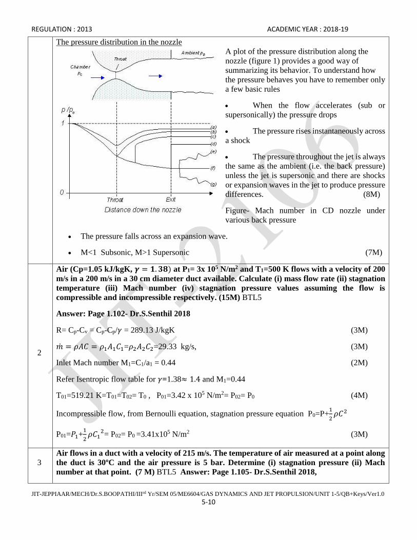
The pressure distribution in the nozzle
A plot of the pressure distribution along the
nozzle (figure 1) provides a good way of
summarizing its behavior. To understand how
the pressure behaves you have to remember only
a few basic rules
• When the flow accelerates (sub or
supersonically) the pressure drops
• The pressure rises instantaneously across
a shock
• The pressure throughout the jet is always
the same as the ambient (i.e. the back pressure)
unless the jet is supersonic and there are shocks
or expansion waves in the jet to produce pressure
differences. (8M)
Figure- Mach number in CD nozzle under
various back pressure
• The pressure falls across an expansion wave.
• M<1 Subsonic, M>1 Supersonic (7M)
2
Air (Cp=1.05 kJ/kgK, 𝜸 = 𝟏. 𝟑𝟖) at P1= 3x 10⁵ N/m2 and T1=500 K flows with a velocity of 200
m/s in a 200 m/s in a 30 cm diameter duct available. Calculate (i) mass flow rate (ii) stagnation
temperature (iii) Mach number (iv) stagnation pressure values assuming the flow is
compressible and incompressible respectively. (15M) BTL5
Answer: Page 1.102- Dr.S.Senthil 2018
R= Cp-Cv = Cp-Cp/𝛾 = 289.13 J/kgK (3M)
�̇� = 𝜌𝐴𝐶 = 𝜌1𝐴1𝐶1=𝜌2𝐴2𝐶2=29.33 kg/s, (3M)
Inlet Mach number M1=C1/a1 = 0.44 (2M)
Refer Isentropic flow table for 𝛾=1.38≈ 1.4 and M1=0.44
T01=519.21 K=T01=T02= T0 , P01=3.42 x 10⁵ N/m2= P02= P0 (4M)
Incompressible flow, from Bernoulli equation, stagnation pressure equation P0=P+1
2𝜌𝐶2
P01=𝑃1+1
2𝜌𝐶1
2= P02= P0 =3.41x10⁵ N/m2 (3M)
3
Air flows in a duct with a velocity of 215 m/s. The temperature of air measured at a point along
the duct is 30ºC and the air pressure is 5 bar. Determine (i) stagnation pressure (ii) Mach
number at that point. (7 M) BTL5 Answer: Page 1.105- Dr.S.Senthil 2018,

REGULATION : 2013 ACADEMIC YEAR : 2018-19
JIT-JEPPIAAR/MECH/Dr.S.BOOPATHI/IIIrd Yr/SEM 05/ME6604/GAS DYNAMICS AND JET PROPULSION/UNIT 1-5/QB+Keys/Ver1.0
5-11
(ii) Carbon dioxide expands isentropically through a nozzle from a pressure of 3.2 bar to 1 bar.
If the initial temperature is 475 K, determine the final temperature, the enthalpy drop and the
change in internal energy. (8 M) BTL5 Answer: Page 1.106- Dr.S.Senthil
(i) a=√𝛾𝑅𝑇=348.92 m/s,
Mach number M= C/a = 0.16
Refer Isentropic flow table for 𝛾=1.4 and M=0.616≈ 0.62
P/P0 =0.772, P0=6.47 x 10⁵ N/m2 (7M)
(ii) Refer gas tables for gas dynamic properties of carbon dioxide at various temperature.
At T1=475 K≈ 473 𝐾
Cp=993 /kgK, Cv=804 J/kgK, 𝛾 = 1.237, R=189 J/kgK
𝑇2
𝑇1= (
𝑃2
𝑃1)
𝛾−1𝛾
==> 𝑇2 = 380.11 𝐾
∆ℎ = 𝐶𝑝∆𝑇 = 𝐶𝑝(𝑇2 − 𝑇1) = 94.2 𝑥 103𝐽
𝑘𝑔
Change in internal energy
∆𝑢 = 𝐶𝑣∆𝑇 = 𝐶𝑣(𝑇1 − 𝑇2) = 79.29𝑥 103 𝐽
𝑘𝑔 (8M)
4
Air is discharged from a receiver at P0=6.91 bar and T0=325ºC through a nozzle to a pressure
of 0.98 bar. If the flow rate is 3600 kg/h. Determine for isentropic flow (i) Area, Pressure and
velocity at throat (ii) Area and Mach number at exit and (iii) Maximum possible velocity. (15
M) BTL5
Answer: Page 2.88- Dr.S.Senthil
At throat section (*) M=1, Refer Isentropic flow table 𝛾=1.4 and M=1
T*=498.73 K, P* = 3.65 x 10⁵ N/m2 , C*=√𝛾𝑅𝑇∗=447.65 m/s (5M)
Mass flow rate �̇� = 𝜌 ∗A*C*, A*=8.76 x10⁻⁴ m2, (2M)
From given data P2/P0=0.142,
Refer Isentropic flow table 𝛾=1.4 and P2/P0=0.142
M2=1.93, A2=13.9 x10⁻⁴ m2, (5M)
𝐶𝑚𝑎𝑥
𝐶∗ = √𝛾+1
𝛾−1 𝐶𝑚𝑎𝑥 = 1096.51 𝑚/𝑠 (3M)

REGULATION : 2013 ACADEMIC YEAR : 2018-19
JIT-JEPPIAAR/MECH/Dr.S.BOOPATHI/IIIrd Yr/SEM 05/ME6604/GAS DYNAMICS AND JET PROPULSION/UNIT 1-5/QB+Keys/Ver1.0
5-12
Subject Code : ME6604 Year/Semester : III/ 06
Subject Name : Gas Dynamics and Jet Propulsion Subject Handler : Dr. S. Boopathi
UNIT II FLOW THROUGH DUCTS
Flows through constant area ducts with heat transfer (Rayleigh flow) and Friction (Fanno flow) – variation
of flow properties.
PART * A
Q.No. Questions
1.
What do you mean by friction chocking? (Nov/Dec 2015) BTL1
Flow with friction in the Fanno flow, the restriction flow occurs due to chocking, is called friction
chocking.
2
Complete the following table with increases, decreases, remains constant for a flow through a
constant area duct with heat transfer:
Static Temperature-
Subsonic flow: Heating------- Cooling---------
Supersonic flow: Heating-------------- Cooling-------------. (Nov/Dec 2015) BTL4
Static Temperature- Subsonic flow : Heating:-remains constant-Cooling: Decreases
Supersonic flow: Heating-Increases- Cooling-Decreases.
3
What is meant by stagnation pressure? (April/May 2015) BTL1
Stagnation pressure is the pressure of the gas when it is isentropically decelerate to zero velocity at
zero elevation. Po/P = (To/T) power of (ν/ν-1).
4 What is Fanno flow? (April/May 2015) BTL1
Flow in a constant area duct with friction and without heat transfer is known as Fanno flow.
5
Air at Po=10 bar and To=400K is supplied to a 50 mm diameter pipe, the friction factor for
the pipe surface is 0.002. If the Mach number changes from 3 at entry to 1 at the exit.
Determine the length of the pipe. (Nov/Dec 2014) BTL5
4fL/D = 0.522 (M1=3, ν=1.4) , 4fL/D = 0 (M2=1, ν=1.4) , L= 3.26m
6
What are the assumptions made for Fanno flow? And give the two practical examples where
the Fanno flow occurs. (Nov/Dec 2014) BTL1
One dimensional, steady flow, flow takes place in constant sectional area. Flow in air breathing
engine, flow of fluids in long pipes
7 Give assumption made on Rayleigh flow. (May /June 2014) BTL3
REGULATION : 2013 ACADEMIC YEAR : 2018-19
JIT-JEPPIAAR/MECH/Dr.S.BOOPATHI/IIIrd Yr/SEM 05/ME6604/GAS DYNAMICS AND JET PROPULSION/UNIT 1-5/QB+Keys/Ver1.0
5-13
Fluid is perfect gas, flow is one dimensional steady and duct area is constant, effect of friction is
negligible, No external work and change due to elevation.
8
Define critical condition in Fanno flow. (May /June 2014) BTL1
Due to friction in subsonic or supersonic flow in a constant area duct, flow will reach the critical
condition (*) where the Mach number M=1 and the mass flow reach the maximum value. If the
length of pipe is increased further, will not give any effect on mass flow rate.
9 What is impulse function and give its uses? (May /June 2013) BTL1
The sum of force (pA) and Impulse force (ρAc2) F=pA+ρAc2.
10
Give the expression for T0/T and T*/T for isentropic flow through variable area in terms of
Mach number. (May /June 2013) BTL1
To/T = 1+ (ν-1)/2 * M2, T*/T=2/ν+1 + (ν-1)/(ν+1)M2.
11
What is meant by isentropic flow with variable area? BTL2
A steady one dimensional isentropic flow in a variable area passages is called “variable area flow”.
The heat transfer is negligible and there are no other irreversibility due to fluid friction, etc.
12 What is the effect of pressure in diffusers and nozzle? BTL3
Diffusers => increase in pressure Nozzles => decrease in pressure
13
Describe the function of a nozzle and a diffuser. BTL2
The main function a nozzle is to accelerate the flow i.e. increase in velocity and decrease in pressure
of the flowing fluid. Whereas, the function of a diffuser is to decelerate the flow i.e, increase in
pressure and decrease in velocity of the flowing fluid.
14 Is the flow through a nozzle an irreversible process? BTL4
Yes. In actual practice, all the processes are irreversible due to friction.
15
When will the convergent-divergent nozzle have the maximum discharge rate? BTL3
From continuity equation
m Ac = Constant
mAc
A = discharge rate
The discharge rate will be maximum only at the throat section. Where Mach number M=1.
16
Write the Fliegner’s formula. BTL1
1
2 10Max
0
0max
0
Tm 2For air 1.4 and R 287 J/Kg K SI units
A P R
Tm 0.0404 Fliegner 's formula
A P

REGULATION : 2013 ACADEMIC YEAR : 2018-19
JIT-JEPPIAAR/MECH/Dr.S.BOOPATHI/IIIrd Yr/SEM 05/ME6604/GAS DYNAMICS AND JET PROPULSION/UNIT 1-5/QB+Keys/Ver1.0
5-14
17
What is impulse function and give its uses? BTL2
Impulse function is defined as the sum of pressure force and inertia force. Impulse function
F = Pressure force A + inertia force Ac2.
Since the unit of both the quantities are same as unit of force, it is very convenient for solving
jet propulsion problems. The thrust exerted by the following fluid between two sections can be
obtained by using change in impulse function.
18
What is chocked flow? State the necessary conditions for this flow to occur in a nozzle. BTL1
When the back pressure is reduced in a nozzle, the mass flow rate will increase. The maximum mass
flow conditions are reached when the back pressure is equal to the critical pressure. When the back
pressure is reduced further, the mass flow rate will not change and is constant. The condition of flow
is called “chocked flow”. The necessary conditions for this flow to occur in a nozzle is : the nozzle
exit pressure ration must be equal to the critical pressure ration where the Mach number M=1.
19 Give the important uses of nozzle and diffuser. BTL3
1. Used in all types of jet propulsion engines, turbo-jet, turboprop, ram jet engines, etc.
2. Used in rocket propulsion systems.
20
Give the important difference between nozzle and venturi. BTL4
NOZZLE VENTURI
1. The flow is accelerated continuously i.e.,
Mach number and velocity increases
continuously.
1. The flow is accelerated up to M=1 and then
Mach number is decreased.
2. Used to increase velocity and Mach
number.
2. Used for flow measurement. (discharge)
3. Generally convergent portion is short. 3. Convergent and divergent portions are equal.
21
What is the pressure ratio between the inlet and throat for isentropic flow of air? BTL1
y
y 1
2
P y 1
(y 1)P2 1 M
2
Part B
1
Given adiabatic flow (Rayleigh flow) of dry air having of some section a Mach number is equal
to 3 and a stagnation temperature of 300 K, while the static pressure is 0.5 bar. For some other
section where Mach number is 1.5. Find (i) Stagnation temperature, (ii) Stagnation Pressure,
(iii) Static pressure and (iv) Amount of heat transferred that caused the reduction in Mach
number. (13 M) (Nov 95) BTL5
Answer: Page 3.65- Dr.S.Senthil 2013
(i) From Isentropic flow table, P01=18.38 x10⁵ N/m2 (3M)
(ii) Refer Rayleigh flow table 𝛾 = 1.4 𝑎𝑛𝑑 𝑀1 = 3
P1*=2.84 x10⁵ N/m2 =P2
*, P01* =5.36 x10⁵ N/m2 =P02
*, T01*= 458.72 K=T02
* (5M)

REGULATION : 2013 ACADEMIC YEAR : 2018-19
JIT-JEPPIAAR/MECH/Dr.S.BOOPATHI/IIIrd Yr/SEM 05/ME6604/GAS DYNAMICS AND JET PROPULSION/UNIT 1-5/QB+Keys/Ver1.0
5-15
(iii) Refer Rayleigh flow table 𝛾 = 1.4 𝑎𝑛𝑑 𝑀1 = 1.5
P2=1.64 x10⁵ N/m2 , P02 =6.013 x10⁵ N/m2 , T02= 416.97 K
Heat transfer Q = m Cp( 𝑇02 − 𝑇01)=1.17 x10⁵ J/kg (5M)
2
The data for a gas (ᵞ = 1.3, Cp=2.144 kJ/kgK) at entry of combustion chamber are C1=150 m/s,
P1=4 bar and T1=395K, if the exit Mach number is 0.78, calculate the following (i) The initial
Mach number, (ii) Final pressure, temperature and velocity of the gas and (iii) Stagnation
pressure loss. (13 M) (April-May 2016) BTL5
Answer: Page 3.50- Dr.S.Senthil
Mach number M1=0.305
(i) Refer isentropic flow table 𝛾 = 1.3 𝑎𝑛𝑑 𝑀1 = 0.3
T01=400.20 K, P01=4.23 x10⁵ N/m2 , (3M)
(ii) Refer Rayleigh flow table 𝛾 = 1.3 𝑎𝑛𝑑 𝑀1 = 3
P1*=1.94 x10⁵ N/m2 =P2
*, P01* =3.55 x10⁵ N/m2 =P02
*, T1*= 1034.032 K=T2
*
, T01*= 1191.07 K=T02
* , C1*=810.81 m/s =C2
* (5M)
(iii) Refer Rayleigh flow table 𝛾 = 1.3 𝑎𝑛𝑑 𝑀1 = 0.78
P2=2.49 x10⁵ N/m2 , P02=3.63 x10⁵ N/m2 , T2=1037.13 K, T02=1133.89 K, C2=633.24 m/s
Stagnation pressure loss ∆𝑃0 = 𝑃02 − 𝑃01 = 0.6 x 10⁵ N/m2
Stagnation enthalpy rise ∆ℎ0 = 𝐶𝑝(𝑇02 − 𝑇01) =𝐶𝑎𝑙𝑜𝑟𝑖𝑓𝑖𝑐 𝑣𝑎𝑙𝑢𝑒 𝑜𝑓 𝑓𝑢𝑒𝑙
𝐴𝑖𝑟 𝑓𝑢𝑒𝑙 𝑟𝑎𝑡𝑖𝑜+1
Air fuel ratio = 25.70: 1 (5M)
3
A circular duct passes 8.25 kg/s of air at an exit Mach number of 0.5. The entry pressure and
temperature are 3.5 bar and 38ºC respectively and coefficient of friction is 0.005. If the Mach
number at entry is 0.15, determine (i) Diameter of the duct, (ii) Length of the duct, (iii) Pressure
and temperature at the exit, and (iv) Stagnation pressure loss. (13 M) (May-June 2016) (May-
June 2012) BTL5
Answer: Page 3.195- Dr.S.Senthil
(i) Refer isentropic flow table 𝛾 = 1.4 𝑎𝑛𝑑 𝑀1 = 0.15
T01=312.256 K, P01=3.55 x10⁵ N/m2, (3M)
(ii) Refer Fanno flow table 𝛾 = 1.4 𝑎𝑛𝑑 𝑀1 = 0.15
P1*=0.478 x10⁵ N/m2 =P2
*, P01* =0.9037 x10⁵ N/m2 =P02
*, T1*= 260.35 K=T2
*,
T01*= 1191.07 K=T02
* , C1*=323.32 m/s =C2
* (5M)
REGULATION : 2013 ACADEMIC YEAR : 2018-19
JIT-JEPPIAAR/MECH/Dr.S.BOOPATHI/IIIrd Yr/SEM 05/ME6604/GAS DYNAMICS AND JET PROPULSION/UNIT 1-5/QB+Keys/Ver1.0
5-16
(iii) Refer Fanno flow table 𝛾 = 1.4 𝑎𝑛𝑑 𝑀1 = 0.5
P2=1.021 x10⁵ N/m2 , P02=1.210 x10⁵ N/m2 , T2=297.58 K,
Diameter of the duct
Mass flow rate �̇� = 𝜌𝐴𝐶 = 𝜌1𝐴1𝐶1 D1= D2=D=0.224 m,
Length of the duct, 4�̅�𝐿
𝐷= (
4�̅�𝐿𝑀𝑎𝑥
𝐷)
𝑀1
− (4�̅�𝐿𝑀𝑎𝑥
𝐷)
𝑀2
= 27.285 L=305.59 m
Stagnation pressure loss ∆𝑃0 = 𝑃02 − 𝑃01 = 2.34 x 10⁵ N/m2 (5M)
4
Air at an inlet temperature of 60ºC flows with subsonic velocity through an insulated pipe
having inside diameter of 50 mm and a length of 5 m. The pressure at the exit of the pipe is 101
kPa and the flow is chocked at the end of the pipe. If the friction factor 4f = 0.005, determine
the inlet Mach number, the mass flow rate and the exit temperature. (13 M) (Dec 2003) BTL5
Answer: Page 3.188- Dr.S.Senthil
Flow is chocked at the end of the pipe. It means at the end of the pipe Mach number value is one.
M2=1,
(i) Refer Fanno flow table 𝛾 = 1.4 𝑎𝑛𝑑 𝑀2 = 1
P2 = 1.01 x10⁵ N /m2 =P2*, (5M)
4�̅�𝐿
𝐷= (
4�̅�𝐿𝑀𝑎𝑥
𝐷)
𝑀1
− (4�̅�𝐿𝑀𝑎𝑥
𝐷)
𝑀2
, (4�̅�𝐿𝑀𝑎𝑥
𝐷)
𝑀1
= 0.5 refer Fanno flow table, M1=0.6,
P1=1.78 x10⁵ N /m2 , T1*= 297.58 K=T2
* (5M)
Mass flow rate �̇� = 𝜌𝐴𝐶 = 𝜌1𝐴1𝐶1 = 0.802 𝑘𝑔/𝑠 (3M)
5
Air is heated in a constant area duct from a Mach number of 0.2 to 0.8. The inlet stagnation
conditions are 2 bar and 93ºC. Determine the stagnation conditions of air at exit, the amount of
heat transferred per unit flow and change in entropy. (13 M) (Nov 1996) BTL5
Answer: Page 3.68- Dr.S.Senthil
Refer isentropic flow table 𝛾 = 1.4 𝑎𝑛𝑑 𝑀1 = 0.2
T1= 363.07 K, P1=1.94 x10⁵ N /m2 (3M)
(ii) Refer Rayleigh flow table 𝛾 = 1.4 𝑎𝑛𝑑 𝑀1 = 0.2
P1*=0.853 x10⁵ N/m2 =P2
*, P01* =1.619 x10⁵ N/m2 =P02
*, T1*= 1753.96 K=T2
*, T01*= 2103.44K=T02
*
. (4M)

REGULATION : 2013 ACADEMIC YEAR : 2018-19
JIT-JEPPIAAR/MECH/Dr.S.BOOPATHI/IIIrd Yr/SEM 05/ME6604/GAS DYNAMICS AND JET PROPULSION/UNIT 1-5/QB+Keys/Ver1.0
5-17
(iii) Refer Rayleigh flow table 𝛾 = 1.4 𝑎𝑛𝑑 𝑀1 = 0.8
P2=1.079 x10⁵ N/m2 , P02=1.649 x10⁵ N/m2 , T2=1797.80 K, T02=2027.71 K,
Stagnation pressure loss ∆𝑃0 = 𝑃02 − 𝑃01 = 0.6 x 10⁵ N/m2
Heat transfer Q = m Cp( 𝑇02 − 𝑇01)=1.67 x10⁶ J/kg
Change in entropy =∆𝑠 = 𝐶𝑝𝑙𝑛 ((
𝑇2𝑇1
)
(𝑃2𝑃1
)
𝛾−1𝛾
)=1776.17 J/kgK (6M)
6
Air enters a constant area duct at M1=3, P1=1 atm. and T1=300 K. Inside the heat added per
unit mass is Q=3x10⁵ J/kg. Calculate the flow properties M2, P2, ρ2, T2, T02 and P02 at the exit.
(13 M) (Dec 2003) BTL5
Answer: Page 3.98- Dr.S.Senthil
Refer isentropic flow table 𝛾 = 1.4 𝑎𝑛𝑑 𝑀1 = 3
T01= 840.34 K, P01=36.76 x10⁵ N /m2 (3M)
(ii) Refer Rayleigh flow table 𝛾 = 1.4 𝑎𝑛𝑑 𝑀1 = 3
P1*=5.68 x10⁵ N/m2 =P2
*, P01* =10.73 x10⁵ N/m2 =P02
*, T1*= 1067.61 K=T2
*, T01*= 1284.92=T02
*
ρ1*=1.844 kg/m3 = ρ 2
*
Heat transfer Q = m Cp( 𝑇02 − 𝑇01)=1.67 x10⁶ J/kg==> 𝑇02 =1138.85 K (6M)
𝑇02
𝑇01= 0.886 (iii) Refer Rayleigh flow table 𝛾 = 1.4 𝑎𝑛𝑑
𝑇02
𝑇01= 0.886
P2=2.97 x10⁵ N/m2 , P02=12.61 x10⁵ N/m2 , T2=1797.80 K, ρ1=1.376kg/m3 (4M)
7
Air at M1= 0.2 is expanded from stagnation properties of 200 kPa and 30 through a convergent
nozzle for which the exit Mach number is 0.8. Assume the nozzle is isentropic and flow through
the pipe of diameter 25 mm is adiabatic. Find the length of the pipe and percentage of decrease
in stagnation pressure. Also find the change in entropy for the friction factor 4f=0.005. (13 M)
(Apr 98) BTL5
Answer: Page 3.209- Dr.S.Senthil
(i) Refer Fanno flow table 𝛾 = 1.4 𝑎𝑛𝑑 𝑀1 = 0.2
P01* =67.47 x10³ N/m2 =P02
*, P02 = 70.03 x10³ N/m2 (3M)
Length of the pipe L

REGULATION : 2013 ACADEMIC YEAR : 2018-19
JIT-JEPPIAAR/MECH/Dr.S.BOOPATHI/IIIrd Yr/SEM 05/ME6604/GAS DYNAMICS AND JET PROPULSION/UNIT 1-5/QB+Keys/Ver1.0
5-18
4�̅�𝐿
𝐷= (
4�̅�𝐿𝑀𝑎𝑥
𝐷)
𝑀1
− (4�̅�𝐿𝑀𝑎𝑥
𝐷)
𝑀2
= 27.285 L=72.3 m (4M)
Percentage of decrease in stagnation pressure loss % ∆𝑃0 = (𝑃02 − 𝑃01)/𝑃01 ∗ 100 =64.9 % (3M)
Change in entropy S2-S1/R = ln(𝑃01
𝑃02) = 301.17 𝐽/𝑘𝑔𝐾 (3M)
8
The friction factor for a 50 mm diameter steel pipe is 0.005. At the inlet to the pipe velocity is
70 m/s, temperature is 80ºC and the pressure is 10 bar. Find the temperature, pressure and
Mach number at exit if the pipe is 25 m long. Also determine the maximum possible length. (13
M) (Dec 2005) BTL5
Answer: Page 3.200- Dr.S.Senthil
Mach number M1=0.185
Refer Fanno flow table for 𝛾 = 1.4 𝑎𝑛𝑑 𝑀1 = 0.18
P1*=1.648 x10⁵ N/m2 =P2
*, T1*= 296.14 K=T2
*, (5M)
L max = 46.357 m
4�̅�𝐿
𝐷= (
4�̅�𝐿𝑀𝑎𝑥
𝐷)
𝑀1
− (4�̅�𝐿𝑀𝑎𝑥
𝐷)
𝑀2
==> (4�̅�𝐿𝑀𝑎𝑥
𝐷)
𝑀2
= 8.543 (4M)
Refer Fanno flow table, for 𝛾 = 1.4 𝑎𝑛𝑑 (4�̅�𝐿𝑀𝑎𝑥
𝐷)
𝑀2
= 8.543
P2=7.186 x10⁵ N/m2 , T2=350.92 K (4M)
9
The pressure, temperature and Mach number of air in a combustion chamber are 4 bar, 100ºC
and 0.2 respectively. The stagnation temperature of air in a combustion chamber is increased 3
times its initial value. Calculate (i) The Mach number, pressure and temperature at the exit (ii)
Stagnation pressure loss (iii) Heat supplied per kg of air. (13 M) (Apr 2014) BTL5
Answer: Page 2.21- Dr.S.Senthil 2018
Refer isentropic flow table 𝛾 = 1.4 𝑎𝑛𝑑 𝑀1 = 0.2
T01= 376 K, P01=4.11 x10⁵ N /m2
Refer Rayleigh flow table 𝛾 = 1.4 𝑎𝑛𝑑 𝑀1 = 0.2
P1*=1.759 x10⁵ N/m2 =P2
*, P01* =3.327 x10⁵ N/m2 =P02
*, T1*= 1801.93 K=T2
*, T01*= 2160.91=T02
*
ρ1*=1.844 kg/m3 = ρ 2
* (5M)
Refer Rayleigh flow table 𝛾 = 1.4 𝑎𝑛𝑑𝑇02
𝑇02∗ = 0.529
REGULATION : 2013 ACADEMIC YEAR : 2018-19
JIT-JEPPIAAR/MECH/Dr.S.BOOPATHI/IIIrd Yr/SEM 05/ME6604/GAS DYNAMICS AND JET PROPULSION/UNIT 1-5/QB+Keys/Ver1.0
5-19
M2=0.40, P2=3.449 x10⁵ N/m2 , P02=3.849 x10⁵ N/m2 , T2=1108.18 K (3M)
Stagnation pressure loss ∆𝑃0 = 𝑃01 − 𝑃02 = 0.261 x 10⁵ N/m2 (2M)
Heat transfer Q = m Cp( 𝑇02 − 𝑇01)=755.7 x10³ J/kg (3M)
10
The condition of a gas in a combustion chamber at entry are T1=375K, P1=0.50 bar, C1=70
m/s. The air-fuel ratio is 29 and the calorific value of the fuel is 42 MJ/kg. Calculate (i) The
initial and final Mach number (ii) Final pressure, temperature and velocity of the gas (iii)
Percentage of stagnation pressure loss (iv) Maximum stagnation temperature. Take 𝜸 =𝟏. 𝟒 𝒂𝒏𝒅 𝑹 = 𝟎. 𝟐𝟖𝟕 𝑱/𝒌𝒈𝑲 (13 M) () BTL5
Answer: Page 1.2- Dr.S.Senthil
Mach number at entry M1=0.180,
Refer isentropic flow table 𝛾 = 1.4 𝑎𝑛𝑑 𝑀1 = 0.18
T01= 377.26 K, P01=0.5112 x10⁵ N /m2 (2M)
Refer Rayleigh flow table 𝛾 = 1.4 𝑎𝑛𝑑 𝑀1 = 0.18
P1*=0.218 x10⁵ N/m2 =P2
*, P01* =0.4119x10⁵ N/m2 =P02
*, T1*= 2192.98 K=T2
*, T01*= 2638.18=T02
*
C1*= 945.95 m/s = C 2
* (4M)
Stagnation enthalpy rise due to the combustion of one kg of fuel is 1.4 x10⁶ J/kg, 𝑇02
𝑇02∗ = 0.67
Refer Rayleigh flow table 𝛾 = 1.4 𝑎𝑛𝑑𝑇02
𝑇02∗ = 0.67
M2=0.48, P2=0.3956 x10⁵ N/m2 , P02=0.462 x10⁵ N/m2 , T2=1662.27 K (3M)
% of Stagnation pressure loss ∆𝑃0 =𝑃01−𝑃02
𝑃01𝑥 100 = 9.62% (2M)
Maximum stagnation temperature = 𝑇0𝑚𝑎𝑥 = 𝑇01∗ = 𝑇02
∗ = 𝑇0∗ = 2638.18 𝐾 (2M)
Part * C
1
(i) Derive the expression between the stagnation to static temperature ratio and the Mach
number of the flow. (7)
(ii) Draw the Rayleigh curve and explain the effect of heat transfer on supersonic flow. (8).
1D form of energy conversion equation is

REGULATION : 2013 ACADEMIC YEAR : 2018-19
JIT-JEPPIAAR/MECH/Dr.S.BOOPATHI/IIIrd Yr/SEM 05/ME6604/GAS DYNAMICS AND JET PROPULSION/UNIT 1-5/QB+Keys/Ver1.0
5-20
Here subscript 1 stands for initial state of the fluid and subscript 2 stands for final decelerated
state of fluid. Since, V2=0, lets represent T2=T0 is above equation. Then,
Dividing the above equation by
(7M)
(ii) Explanation and diagram
Figure- T-s diagram (8M)
2 A combustion chamber in a gas turbine plant receives air at 350K, 0.55 bar and 75 m/s. The
air-fuel ratio is 29 and the calorific value of the fuel is 41.87 MJ/kg. Taking 𝜸 = 𝟏. 𝟒 𝒂𝒏𝒅 𝑹 =

REGULATION : 2013 ACADEMIC YEAR : 2018-19
JIT-JEPPIAAR/MECH/Dr.S.BOOPATHI/IIIrd Yr/SEM 05/ME6604/GAS DYNAMICS AND JET PROPULSION/UNIT 1-5/QB+Keys/Ver1.0
5-21
𝟎. 𝟐𝟖𝟕 𝑱/𝒌𝒈𝑲 for the gas, determine (i) The initial and final Mach number (ii) Final pressure,
temperature and velocity of the gas (iii) Percentage of stagnation pressure loss (iv) Maximum
stagnation temperature. (May-June 2016) (April-May 2011) (15 M) BTL5
Answer: Page 2.55- Dr.S.Senthil
Mach number at entry M1=0.199,
Refer isentropic flow table 𝛾 = 1.4 𝑎𝑛𝑑 𝑀1 = 0.20
T01= 352.82 K, P01=0.565 x10⁵ N /m2 (5M)
Refer Rayleigh flow table 𝛾 = 1.4 𝑎𝑛𝑑 𝑀1 = 0.2
P1*=0.2419 x10⁵ N/m2 =P2
*, P01* =0.457x10⁵ N/m2 =P02
*, T1*= 1690.82 K=T2
*,
T01*= 2027.70 K =T02
* , C1*= 824.17 m/s = C 2
* (5M)
Stagnation enthalpy rise due to the combustion of one kg of fuel is 1.4 x10⁶ J/kg, 𝑇02
𝑇02∗ = 0.8588
Refer Rayleigh flow table 𝛾 = 1.4 𝑎𝑛𝑑𝑇02
𝑇02∗ = 0.859
M2=0.64, P2=0.368 x10⁵ N/m2 , P02=0.48 x10⁵ N/m2 , T2=1611.35 K, C2= 515.106 m/s
% of Stagnation pressure loss ∆𝑃0 = 𝑃01 − 𝑃02 = 0.085 𝑥105𝑁/𝑚2
Maximum stagnation temperature = 𝑇0𝑚𝑎𝑥 = 𝑇01∗ = 𝑇02
∗ = 𝑇0∗ = 2027.70 𝐾 (5M)
3
The stagnation temperature of air is raised from 85ºC to 376ºC in a heat exchanger. If the inlet
Mach number is 0.4, determine the final Mach number and percentage drop in pressure. Page
(15 M) (Apr 1998) BTL5
Answer: Page 2.62- Dr.S.Senthil
Refer Rayleigh flow table for 𝛾 = 1.4 𝑎𝑛𝑑 𝑀1 = 0.4 (3M)
T01*= 676.75 K =T02
* 𝑇02
𝑇02∗ = 0.958 (3M)
Refer Rayleigh flow table for 𝛾 = 1.4 𝑎𝑛𝑑𝑇02
𝑇02∗ = 0.955 (3M)
M2=0.78, P2/P2* =1.296, Note inlet Mach number , M1<1, so M2<1 (3M)
Percentage drop in pressure =
𝑃1𝑃1
∗−𝑃2
𝑃2∗
𝑃1𝑃1
∗
x 100 = 33.9 % (3M)
REGULATION : 2013 ACADEMIC YEAR : 2018-19
JIT-JEPPIAAR/MECH/Dr.S.BOOPATHI/IIIrd Yr/SEM 05/ME6604/GAS DYNAMICS AND JET PROPULSION/UNIT 1-5/QB+Keys/Ver1.0
5-22
Subject Code : ME6604 Year/Semester : III/ 06
Subject Name : Gas Dynamics and Jet Propulsion Subject Handler : Dr. S. Boopathi
UNIT III NORMAL AND OBLIQUE SHOCKS
Governing equations – Variation of flow parameters across the normal and oblique shocks – Prandtl –
Meyer relations – Applications. (https://nptel.ac.in/courses/112103021/8)
PART * A
Q. No. Questions
1.
How shock condensation of a shock wave is defined? (Nov/Dec 2015) BTL2
Condensation Shock wave is a special form of shock wave. It occurs in an accelerating supersonic
gas flow as a result of the condensation of vapors contained in the gas. A condensation shock is
usually observed in a supersonic nozzle when the accelerated motion of the gas is accompanied by a
monotonic decrease in the gas’s temperature and a corresponding increase in its relative humidity.
2
What is compression corner? (Nov/Dec 2015) BTL1
Compression corners and shocks impinging on boundary layers are common in scramjet inlets and
isolators. Due to the simplicity of the configuration, compression ramps.
3 What is Oblique shock? (April/May 2015) BTL2
When the shock wave is inclined at an angle to the flow, it is called Oblique shock.
4
What is Prandtl Meyer Relation? (April/May 2015) BTL2
It gives the relationship between the gas velocities before and after the normal shock and the critical
velocity of sound. Mx* X My* =1 or Cx X Cy = a*2.
5
What are the properties changes across a normal shock? Is the flow through a normal shock
an equilibrium one? (Nov/Dec 2014) BTL2
Stagnation pressure decreases, stagnation temperature remains constant.
No, since the fluid properties like pressure, temperature, and density are changed during the normal
shock.
6
Give the difference between normal and oblique shocks. (Nov/Dec 2014) BTL4
Normal Shock: Shock wave is right angle to the flow, one dimensional flow.
Oblique shock: Shock wave is inclined at an angle to the flow, two dimensional flow.
7
Why the efficiency of a machine, experiencing shock wave is considerably low? (May /June
2014) BTL4
Shock may cause boundary layer separation and deviation of flow from its designed direction.
There will be a loss in stagnation pressure and increase in entropy across the shock wave.

REGULATION : 2013 ACADEMIC YEAR : 2018-19
JIT-JEPPIAAR/MECH/Dr.S.BOOPATHI/IIIrd Yr/SEM 05/ME6604/GAS DYNAMICS AND JET PROPULSION/UNIT 1-5/QB+Keys/Ver1.0
5-23
8
What is the use of pitot tube in supersonic flow? (May /June 2014) BTL1
Introduction of pitot tube produces a curved shock a little distance upstream of its mouth. Therefore
it measures the stagnation pressure downstream the shock wave.
9 State assumption made to drive the iso-thermal flow equation. (May /June 2013) BTL3
One dimensional, Constant area duct, Frictional flow at constant temperature, The gas is perfect.
10 Difference between Fanno flow and Rayleigh flow. (May /June 2013) BTL4
Fanno flow-with friction without heat transfer, Rayleigh flow-With heat transfer.
11 Define shock wave. BTL2
A shock wave is a special kind of wave referred to as a steep finite pressure wave. The changes
in the flow properties across such a wave are abrupt.
12
Define Normal shock. BTL1
Normal shock wave is defined as the abrupt jump in pressure when they are at right angles to the
direction of flow.
The normal shock wave is perpendicular to the one dimensional flow.
13
List out some effects of shock in a flow. BTL4
The effects are:
1. Shocks may cause boundary layer separation.
2. Shock derivate the flow from its designated direction.
14
List out the changes in properties before and after the normal shock. BTL4
The change in properties before and after the normal shock is,
i. There is an increase in entropy.
ii. There is stagnation pressure loss.
iii. There is an increase in temperature after the shock.
15
Define Prandtl – Meyer relation. BTL2
The fundamental relation used to compare gas velocities before and after normal shock and to
derive critical velocity of sound is known as Prandtl Meyer relation.
The Prandtl meyer relation of normal shock wave is,
Cx Cy = a*2 i.e Mx My = 1
16
Define Rankine – Hugoniot equation. BTL2
The equation which relates pressure and density ratio across a shock wave in a perfect gas is
known as Rankine – Hugoniot equation.
For normal shock wave,
1 11
1 1 (1) (2)
1 1
1 1
y y
y yx x
y yx x
x x
P
P
17
Define strength of a shock wave. BTL1
The strength of a shock wave is defined as the ratio of pressure increase due to shock to the
initial or upstream pressure.
Py - Px
Strength = _________
Px
REGULATION : 2013 ACADEMIC YEAR : 2018-19
JIT-JEPPIAAR/MECH/Dr.S.BOOPATHI/IIIrd Yr/SEM 05/ME6604/GAS DYNAMICS AND JET PROPULSION/UNIT 1-5/QB+Keys/Ver1.0
5-24
18 What are the effects of normal shocks in a flow through convergent divergent passages? BTL2
In case of convergent divergent passages the normal shock leads to drop in fluid velocity
instantaneously from supersonic to subsonic as the pressure rise across the shock wave front.
19 Define compression shock. BTL2
A shock which occurs in a stream that is supersonic in that upstream from the shock plane and
accompanied by an increase in entropy is known as compression shock.
20
Define Rarefaction shock. BTL2
A shock which is opposite to the compression shock and would accelerate the flow from subsonic to
supersonic velocity is known as rarefaction shock.
21
Give expression for change in entropy across the normal shock in terms of stagnation pressure.
BTL2
Poy
S = - R ln _______
Pox
S – Change in entropy, Poy – Stagnation pressure at downstream,
Pox - Stagnation pressure at upstream of shock, R – Gas constant
22
List out the applications of propagating steep waves (or) shock waves. BTL3
Propagating steep waves of finite amplitude finds applications in,
i. Shock tubes
ii. Supersonic gas ducts
iii. Partial admission turbines
iv. Pulse jet engines.
v. Complex engines
23
List out the applications of supersonic diffuser. BTL3
Supersonic diffusers have applications in
i. Supersonic wind tunnels.
ii. Compressors
iii. Supersonic inlets of aircraft engines and missiles.
24
Give two stages in which diffusion occurs. BTL2
i. Through a normal shock at the entry section
ii. Through isentropic deceleration of the subsonic flow after the shock in the diverging passage.
25
Define Diffuser efficiency. BTL2
Diffuser efficiency is defined as the ratio of change of enthalpy in reversible diffusion to the
change of enthalpy in actual diffusion.
Change of enthalpy in reversible diffusion
D = ____________________________________________________
Change of enthalpy in actual diffusion
h2s – h1
D = ____________
h2 – h1

REGULATION : 2013 ACADEMIC YEAR : 2018-19
JIT-JEPPIAAR/MECH/Dr.S.BOOPATHI/IIIrd Yr/SEM 05/ME6604/GAS DYNAMICS AND JET PROPULSION/UNIT 1-5/QB+Keys/Ver1.0
5-25
26
Define oblique shock wave. BTL2
When the direction of flow is inclined at an oblique angle to the shock wave it si known as
oblique shock wave. It is also known as two dimensional plane shock wave.
27
What is the wave angle of an oblique shock wave? BTL
The wave angle of an oblique shock wave is less than 90o degrees.
28
When oblique shock wave occurs? BTL4
Oblique shock wave occurs when a supersonic flow is deflected inwards (anti clockwise
direction).
29
Give some practical examples of oblique shock waves. BTL4
The practical examples are:
a. At the exit of turbine blade passages with supersonic flow.
b. At the entry of supersonic diffuser of aircraft engines.
c. Drag due to shock on an aerodynamic body.
30
Define wave angle. BTL2
The angle which the oblique shock waves makes with the initial direction of the flow is called
wave angle ().
31
List out the assumptions made in the analysis of oblique shock wave. BTL4
i. Perfect gas,
ii. Steady, adiabatic and friction less flow through stationary oblique shock wave.
iii. Absence of external work and iv. Absence of body forces
32
Give the expression for deflection angle of an oblique shock wave. BTL5
M12 Sin 2 - 2 Cot
tan = ______________________________
2 + M12 ( r – Cos 2 )
33
Give the expression of Mach angle () of an oblique shock wave. BTL5
The expression for Mach angle () of an oblique shock wave is,
= Mach wave = Sin-1 1/M
34
Define shock polar. BTL2
The graphical representation of oblique shock properties is known as shock polar.

REGULATION : 2013 ACADEMIC YEAR : 2018-19
JIT-JEPPIAAR/MECH/Dr.S.BOOPATHI/IIIrd Yr/SEM 05/ME6604/GAS DYNAMICS AND JET PROPULSION/UNIT 1-5/QB+Keys/Ver1.0
5-26
35
Define Prandtl Meyer flow. BTL2
The isentropically accelerating flow over the convex wall is known as Prandtl Meyer flow.
Part B
1
Air flows adiabatically in a pipe. A normal shock wave is formed. The pressure and temperature
of air before the shock are 150 kN/m2 and 25ºC respectively. The pressure just after the normal
shock is 350 kN/m2. Calculate (i) Mach number before the shock, (ii) Mach number, static
temperature and velocity of air after the shock wave, (iii) Increase in density of air, (iv) Loss of
stagnation pressure of air and (v) change in entropy. (13 M) (May 2004) BTL5
Answer: Page 4.67- Dr.S.Senthil
Py/Px=2.333,
Refer Normal shock tables for Py/Px=2.333, 𝛾 = 1.4 (3M)
𝑇𝑦 = 385.61 𝐾, 𝑃0𝑦 = 489.75 𝑥 103 𝑁/𝑚2, 𝑃0𝑥 = 519.9 𝑥 103 𝑁/𝑚2
Stagnation pressure loss ∆𝑃0 = 𝑃0𝑥 − 𝑃0𝑦 = 30.15 x 10³ N/m2
Mach number after the shock My=Cy/ay Cy=281.83 m/s,
Density before shock 𝜌𝑥 =𝑃𝑥
𝑅𝑇𝑥= 1.753 𝑘𝑔/𝑚3 (4M)
Density after the shock 𝜌𝑦 =𝑃𝑦
𝑅𝑇𝑦= 3.162 𝑘𝑔/𝑚3 (3M)
Increase in density = 1.409 kg/m3
Change in entropy, ∆𝑆 = 𝑅 𝑙𝑛 (𝑃0𝑥
𝑃0𝑦) = 17.148 𝐽/𝑘𝑔𝐾 (3M)
2
When a convergent divergent nozzle is operated at off-design condition a normal shock occurs
at a section where the cross sectional area is 18.75 cm2 in the diverging portion. At inlet to the
nozzle the stagnation state is given as 0.21 MPa and 36ºC. The throat area is 1.25 cm2 and exit
area is 25 cm2. Estimate the exit Mach number, exit pressure and loss in stagnation pressure
for flow through nozzle. (13 M) (Dec 2005) BTL5
Answer: Page 4.77- Dr.S.Senthil
𝐴𝑥
𝐴𝑦= 1.5,
Refer Isentropic flow table for 𝐴𝑥
𝐴𝑦= 1.5, 𝛾 = 1.4 Mx=1.86 (2M)
Note upstream Mach number, Mx value is always greater than 1
Refer Normal shock Table for Mx=1.86 and 𝛾 = 1.4, My=0.604, 𝑃0𝑦 = 1.65 x 10⁵ N/m2 (3M)

REGULATION : 2013 ACADEMIC YEAR : 2018-19
JIT-JEPPIAAR/MECH/Dr.S.BOOPATHI/IIIrd Yr/SEM 05/ME6604/GAS DYNAMICS AND JET PROPULSION/UNIT 1-5/QB+Keys/Ver1.0
5-27
Refer Isentropic flow table for My=0.604 and 𝛾 = 1.4 , 𝐴𝑦∗ = 1.578 𝑥 10−3𝑚2 (3M)
𝐴2
𝐴𝑦∗ = 1.584, (1M)
Refer Isentropic flow table , 𝐴2
𝐴𝑦∗ = 1.584 and 𝛾 = 1.4
M2=0.4, P2=1.476 x 10⁵ 𝑁/𝑚2
We Know that, Stagnation pressure loss, ∆𝑃 = 𝑃0𝑥 − 𝑃0𝑦 = 0.45 𝑥 105𝑁/𝑚2 (4M)
3
A gas at a pressure of 340 mbar, temperature of 355 K and entry Mach number of 1.4 is
expanded isentropically to 140 mbar. Calculate the following (i) Deflection angle (ii) Final Mach
number and (iii) Final temperature of the gas. (13 M) (April-May 2015) (May-June 2014)(April-
May2011) BTL5
Answer: Page 4.131- Dr.S.Senthil
i) Refer isentropic flow table 𝛾 = 1.3 𝑎𝑛𝑑 𝑀1 = 1.4
T01=459.24 K= T02, P01=1.039 x10⁵ N/m2 , P2/P02 =0.134 (3M)
Refer Isentropic flow table for P2/P02 =0.135 and 𝛾 = 1.3
M2=1.98, T2=288.86 K
Refer Prandtl-Meyar function table for M2=1.4 and 𝛾 = 1.3 𝜔(𝑀1) = 9.542 (3M)
Refer Prandtl-Meyar function table for M2=1.98 and 𝛾 = 1.3 𝜔(𝑀2) = 28.06 (3M)
Deflection angle 𝛿 = 𝜔(𝑀1) − 𝜔(𝑀2) = −18.51º (4M)
4
A pitot tube kept in a supersonic wind tunnel forms a bow shock, ahead of it. The static pressure
upstream of the shock is 16 kPa and the pressure at the mouth is 70 kPa. Estimate the Mach
number of the tunnel. If the stagnation temperature is 300ºC, calculate the static temperature
and total pressure upstream and downstream of tube. (13 M) (Dec 2003) (Dec 2005) BTL5
Answer: Page 4.80- Dr.S.Senthil
𝑃0𝑦
𝑃𝑥= 4.375 (2M)
Refer Normal shocks table for 𝑃0𝑦
𝑃𝑥= 4.375 and 𝛾 = 1.4 (1M)
Mx=1.74, Pox=0.834 x10⁵ N/𝑚2 (2M)
𝑇0
𝑇= 1 +
𝛾−1
2𝑀2,
𝑇0𝑥
𝑇𝑥= 1 +
𝛾−1
2𝑀𝑥
2 Tx=356.89 K, (4M)
From Table, 𝑇𝑦
𝑇𝑥= 1.487, ===> 𝑇𝑦 = 350.69 K (4M)
REGULATION : 2013 ACADEMIC YEAR : 2018-19
JIT-JEPPIAAR/MECH/Dr.S.BOOPATHI/IIIrd Yr/SEM 05/ME6604/GAS DYNAMICS AND JET PROPULSION/UNIT 1-5/QB+Keys/Ver1.0
5-28
5
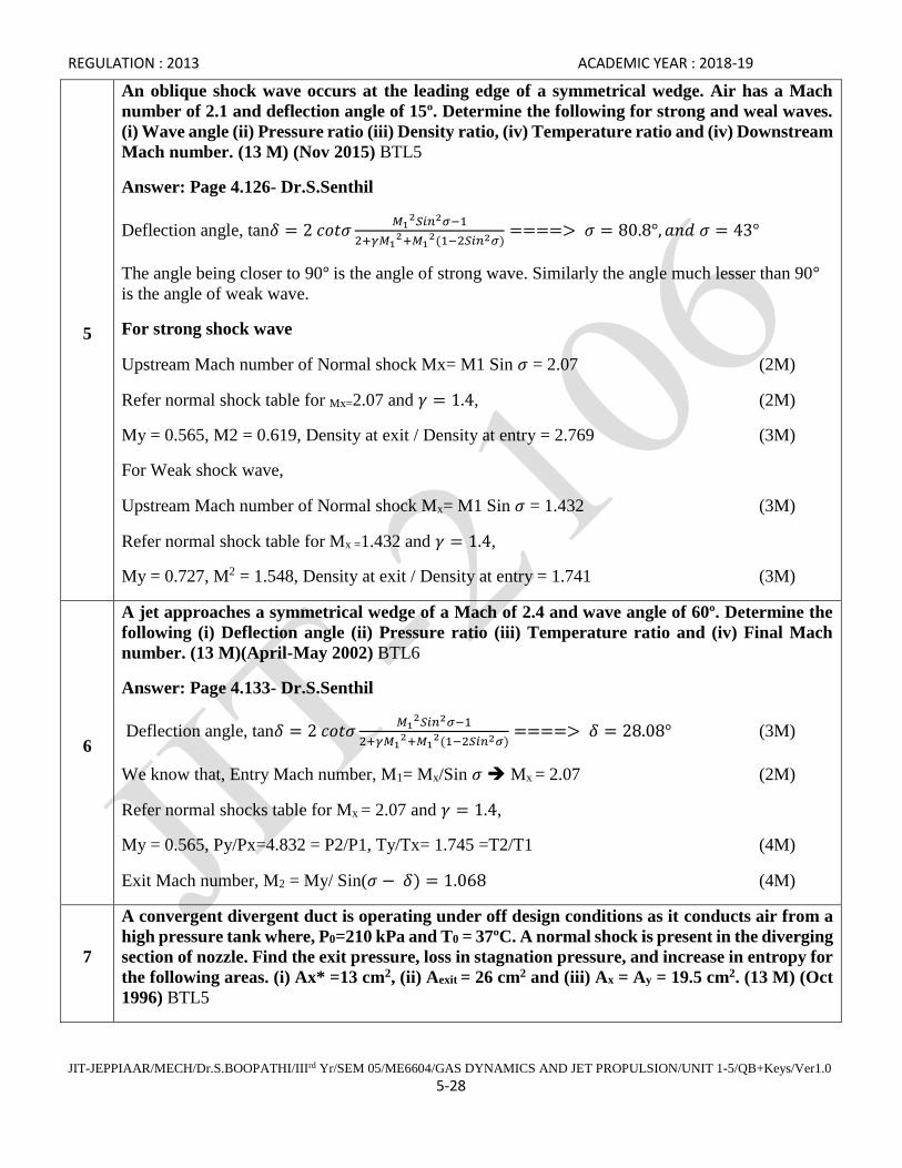
An oblique shock wave occurs at the leading edge of a symmetrical wedge. Air has a Mach
number of 2.1 and deflection angle of 15º. Determine the following for strong and weal waves.
(i) Wave angle (ii) Pressure ratio (iii) Density ratio, (iv) Temperature ratio and (iv) Downstream
Mach number. (13 M) (Nov 2015) BTL5
Answer: Page 4.126- Dr.S.Senthil
Deflection angle, tan𝛿 = 2 𝑐𝑜𝑡𝜎𝑀1
2𝑆𝑖𝑛2𝜎−1
2+𝛾𝑀12+𝑀1
2(1−2𝑆𝑖𝑛2𝜎)====> 𝜎 = 80.8°, 𝑎𝑛𝑑 𝜎 = 43°
The angle being closer to 90° is the angle of strong wave. Similarly the angle much lesser than 90°
is the angle of weak wave.
For strong shock wave
Upstream Mach number of Normal shock Mx= M1 Sin 𝜎 = 2.07 (2M)
Refer normal shock table for Mx=2.07 and 𝛾 = 1.4, (2M)
My = 0.565, M2 = 0.619, Density at exit / Density at entry = 2.769 (3M)
For Weak shock wave,
Upstream Mach number of Normal shock Mx= M1 Sin 𝜎 = 1.432 (3M)
Refer normal shock table for Mx =1.432 and 𝛾 = 1.4,
My = 0.727, M2 = 1.548, Density at exit / Density at entry = 1.741 (3M)
6
A jet approaches a symmetrical wedge of a Mach of 2.4 and wave angle of 60º. Determine the
following (i) Deflection angle (ii) Pressure ratio (iii) Temperature ratio and (iv) Final Mach
number. (13 M)(April-May 2002) BTL6
Answer: Page 4.133- Dr.S.Senthil
Deflection angle, tan𝛿 = 2 𝑐𝑜𝑡𝜎𝑀1
2𝑆𝑖𝑛2𝜎−1
2+𝛾𝑀12+𝑀1
2(1−2𝑆𝑖𝑛2𝜎)====> 𝛿 = 28.08° (3M)
We know that, Entry Mach number, M1= Mx/Sin 𝜎 Mx = 2.07 (2M)
Refer normal shocks table for Mx = 2.07 and 𝛾 = 1.4,
My = 0.565, Py/Px=4.832 = P2/P1, Ty/Tx= 1.745 =T2/T1 (4M)
Exit Mach number, M2 = My/ Sin(𝜎 − 𝛿) = 1.068 (4M)
7
A convergent divergent duct is operating under off design conditions as it conducts air from a
high pressure tank where, P0=210 kPa and T0 = 37ºC. A normal shock is present in the diverging
section of nozzle. Find the exit pressure, loss in stagnation pressure, and increase in entropy for
the following areas. (i) Ax* =13 cm2, (ii) Aexit = 26 cm2 and (iii) Ax = Ay = 19.5 cm2. (13 M) (Oct
1996) BTL5

REGULATION : 2013 ACADEMIC YEAR : 2018-19
JIT-JEPPIAAR/MECH/Dr.S.BOOPATHI/IIIrd Yr/SEM 05/ME6604/GAS DYNAMICS AND JET PROPULSION/UNIT 1-5/QB+Keys/Ver1.0
5-29
Answer: Page 4.101- Dr.S.Senthil
𝐴𝑥
𝐴𝑥∗ = 1.5 ,
Refer Isentropic flow table for 𝐴𝑥
𝐴𝑥∗ = 1.5 , 𝛾 = 1.4 Mx=1.86 (2M)
Note upstream Mach number, Mx value is always greater than 1
Refer Normal shock Table for Mx=1.86 and 𝛾 = 1.4, My=0.604, 𝑃0𝑦 = 1.65 x 10⁵ N/m2
Refer Isentropic flow table for My=0.60 and 𝛾 = 1.4 , 𝐴𝑦∗ = 1.64 𝑥 10−3𝑚2 (3M)
𝐴2
𝐴𝑦∗ = 1.584 ≈ 1.59,
Refer Isentropic flow table , 𝐴2
𝐴𝑦∗ = 1.59 and 𝛾 = 1.4
M2=0.4, P2=1.476 x 10⁵ 𝑁/𝑚2 (3M)
We Know that, Stagnation pressure loss, ∆𝑃 = 𝑃0𝑥 − 𝑃0𝑦 = 0.45 𝑥 105𝑁/𝑚2 (2M)
Change in entropy, ∆𝑆 = 𝑅 𝑙𝑛 (𝑃0𝑥
𝑃0𝑦) = 69.2 𝐽/𝑘𝑔𝐾 (3M)
8
An oblique shock wave at an angle of 33º occurs at the leading edge of a symmetrical wedge.
Air has a Mach number of 2.1 upstream temperature of 300 K and upstream pressure of 11
bar. Determine the following (i) Downstream pressure (ii) Downstream temperature (iii) Wedge
angle (iv) Downstream Mach number. (13 M) (May 2014) BTL5
Answer: Page 4.137- Dr.S.Senthil
Mach number of oblique shock, 𝑀1 =𝑀𝑥
sin 𝜎𝑀𝑥 = 1.143 (3M)
Refer Normal shock table for 𝑀𝑥 = 1.143 𝑎𝑛𝑑 𝛾 = 1.4
My=0.882, Ty=327 K, Py=14.83 x 10⁵ 𝑁/𝑚2 (3M)
Deflection angle, tan𝛿 = 2 𝑐𝑜𝑡𝜎𝑀1
2𝑆𝑖𝑛2𝜎−1
2+𝛾𝑀12+𝑀1
2(1−2𝑆𝑖𝑛2𝜎)====> 𝛿 = 5.44° (3M)
Downstream Mach number of Oblique shock, M2 = My/ Sin(𝜎 − 𝛿) = 1.91 (4M)
9
A jet of air at 270 K and 0.7 bar has an initial Mach number of 1.9. If it passes through a normal
shock wave, determine the following for downstream of the shock. (i) Mach number (ii)
Pressure (iii) Temperature (iv) Speed of sound (v) Jet velocity (vi) Density. (13 M) (April 2004)
BTL6
Answer: Page 3.34- Dr.S.Senthil 2018

REGULATION : 2013 ACADEMIC YEAR : 2018-19
JIT-JEPPIAAR/MECH/Dr.S.BOOPATHI/IIIrd Yr/SEM 05/ME6604/GAS DYNAMICS AND JET PROPULSION/UNIT 1-5/QB+Keys/Ver1.0
5-30
Refer normal shock Mx=1.9 and 𝛾 = 1.4
My=0.596, Py=2.831 x 10 5 N/m2, (4M)
Ty=434.16 K, ay= 417.66 m/s, (5M)
Cy= 248.93 m/s, 𝜌𝑦 = 2.27 𝑘𝑔/𝑚3 (4M)
10
A convergent divergent nozzle is designed expand air from a reservoir in which the pressure is
800 kPa and temperature is 40C to give a Mach number at exit of 2.5. The throat area is 25 cm2
find (i) Mass flow rate (ii) Exit area (iii) When a normal shock appears at a section where the
area is 40 cm2, determine the pressure and temperature at exit. Throat. (13 M) BTL6.
Answer: Page 3.3- Dr.S.Senthil 2018
Refer isentropic flow table 𝛾 = 1.4 𝑎𝑛𝑑 𝑀2 = 2.5
T2=138.97 K, P2=0.468 x10⁵ N/m2, A2=6.59 x 10⁻³ m2
Mass flow rate �̇� = 𝜌𝐴𝐶 = 𝜌1𝐴1𝐶1 = 𝝆𝟐𝑨𝟐𝑪𝟐 = 4.568 𝑘𝑔/𝑠 (3M)
Normal shock appears at Ax = 40 x 10-4 m2,
Ax/Ax*=1.6 Refer isentropic flow table for Ax/Ax*=1.6 , and 𝛾 = 1.4
Upstream Mach number Mx always greater than 1, Mx=1.94 (2M)
Refer normal shock table for Mx=1.94 and 𝛾 = 1.4
My=0.588, P0y = 5.992 x 10⁵ N/m2, (2M)
Refer Isentropic flow table for My=0.59 and 𝛾 = 1.4 Ay/Ay*=1.2 Ay*=3.33 x 10⁻³ m2
A2/Ay*=1.977 , (3M)
Refer Isentropic flow table for A2/Ay*=1.976 and 𝛾 = 1.4
M2=0.31, P2=5.60x10⁵ N/m2, T2=307.05 K (3M)
Part *C
1
(i) Derive the equation for Mach number in the downstream of the normal shock wave.
(ii) Derive the equation for static pressure ratio across the shock wave. (15 M) BTL3
Answer: Page 4.101- Dr.S.Senthil
A normal shock wave is one of the situations where the flow properties change drastically in one
direction. The shock wave stands perpendicular to the flow as shown in Fig. 4.4.4. The quantitative
analysis of the changes across a normal shock wave involves the determination of flow properties.
All conditions of are known ahead of the shock and the unknown flow properties are to be determined

REGULATION : 2013 ACADEMIC YEAR : 2018-19
JIT-JEPPIAAR/MECH/Dr.S.BOOPATHI/IIIrd Yr/SEM 05/ME6604/GAS DYNAMICS AND JET PROPULSION/UNIT 1-5/QB+Keys/Ver1.0
5-31
after the shock. There is no heat added or taken away as the flow traverses across the normal shock.
Hence, the flow across the shock wave is adiabatic.
Fig. Schematic diagram of a standing normal shock wave.
The basic one dimensional compressible flow equations can be written as below;
For a calorically perfect gas, thermodynamic relations can be used,
The continuity and momentum equations can be simplified to obtain,
Since, and , the energy equation is written as,
Both can now be expressed as,
Substitute and solve for

REGULATION : 2013 ACADEMIC YEAR : 2018-19
JIT-JEPPIAAR/MECH/Dr.S.BOOPATHI/IIIrd Yr/SEM 05/ME6604/GAS DYNAMICS AND JET PROPULSION/UNIT 1-5/QB+Keys/Ver1.0
5-32
Recall the relation for and substitute
Substitute and solve for
(9M)
The pressure ratio can be obtained by the combination of momentum and
continuity equations i.e.
(2M)
Substituting the ratio and simplifying for the pressure ratio across the
normal shock, we get, (4M)
2
Derive Rankine-Hugoniot equation. (15 M) BTL3
Answer: Page 4.101- Dr.S.Senthil
Hugoniot equation:
Shock wave compression is an adiabatic and irreversible process; hence shock waves can be treated
as irreversible adiabatic compressors. Let’s calculate the work required for this compression
process.
REGULATION : 2013 ACADEMIC YEAR : 2018-19
JIT-JEPPIAAR/MECH/Dr.S.BOOPATHI/IIIrd Yr/SEM 05/ME6604/GAS DYNAMICS AND JET PROPULSION/UNIT 1-5/QB+Keys/Ver1.0
5-33
(15M)
3
A jet of air entering the subsonic diffuser at P0=1 bar and T=280 K. The entry Mach number
is 2 and the ratio of the exit to entry area of the diffuser is 4. If there is a normal shock wave
just outside the diffuser entry, determine the following for exit (i) Mach number (ii)
temperature (iii) Pressure (iv) Stagnation pressure loss. (15 M) BTL6
Answer: Page 3.45- Dr.S.Senthil 2018
Refer isentropic flow table Mx=M1=2 and 𝛾 = 1.4
Tox=504.50 K, Px= 0.128 x 10⁵ 𝑁/𝑚2, (2M)
Refer normal shock table Mx = 2 and 𝛾 = 1.4
My=0.577, Py=0.576 x 10⁵ 𝑁/𝑚2, Ty=472.36 K (3M)
Refer isentropic flow table for My=0.58 and 𝛾 = 1.4
P0y=0.723 x 10⁵ 𝑁/𝑚2, A2/Ay*=4.852, (5M)
Refer isentropic flow table A2/Ay*=4.852, and 𝛾 = 1.4, take M<1 since it is subsonic
M2=0.12, T2=503.03 K, P2=0.715 x10⁵ 𝑁/𝑚2,
Stagnation Pressure loss ∆𝑃 = 𝑃0𝑥 − 𝑃0𝑦 = 0.277𝑥 105𝑁/𝑚2 (5M)
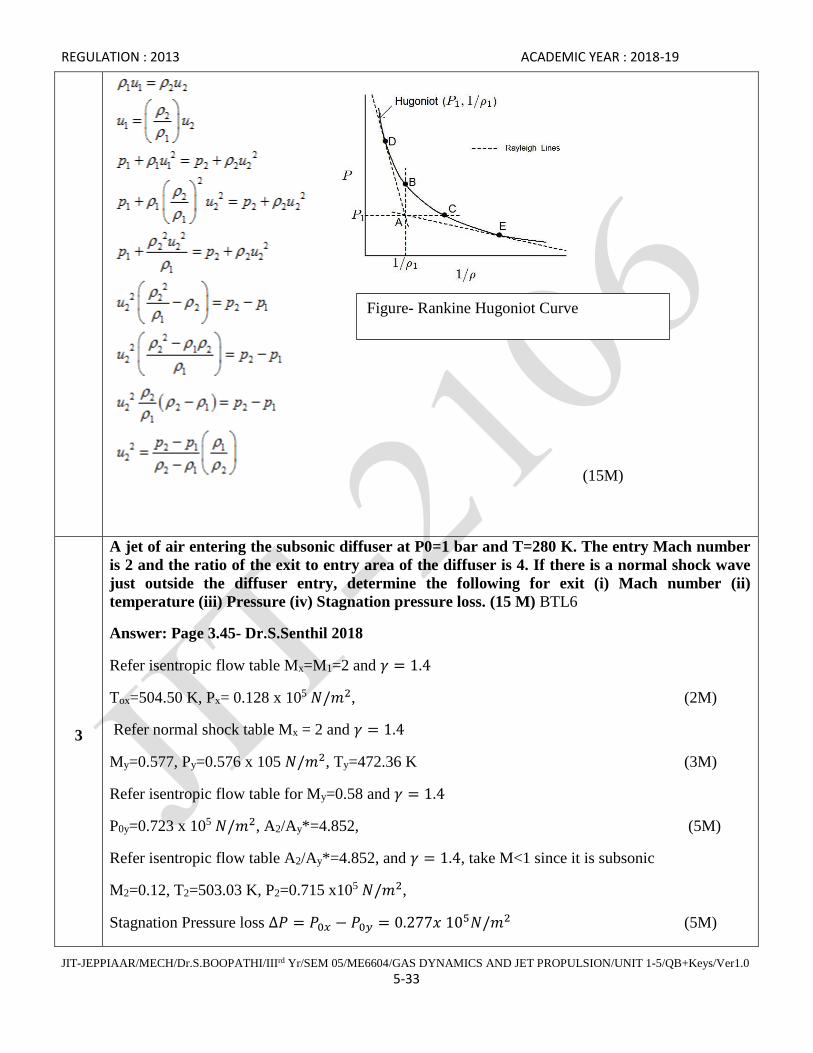
Figure- Rankine Hugoniot Curve
REGULATION : 2013 ACADEMIC YEAR : 2018-19
JIT-JEPPIAAR/MECH/Dr.S.BOOPATHI/IIIrd Yr/SEM 05/ME6604/GAS DYNAMICS AND JET PROPULSION/UNIT 1-5/QB+Keys/Ver1.0
5-34
REGULATION : 2013 ACADEMIC YEAR : 2018-19
JIT-JEPPIAAR/MECH/Dr.S.BOOPATHI/IIIrd Yr/SEM 05/ME6604/GAS DYNAMICS AND JET PROPULSION/UNIT 1-5/QB+Keys/Ver1.0
5-35
Subject Code : ME6604 Year/Semester : III/ 06
Subject Name : Gas Dynamics and Jet Propulsion Subject Handler : Dr. S. Boopathi
UNIT IV JET PROPULSION
Theory of jet propulsion – Thrust equation – Thrust power and propulsive efficiency – Operating principle,
cycle analysis and use of stagnation state performance of ram jet, turbojet, turbofan and turbo prop engines.
PART * A
Q.No. Questions
1.
What is the significance of low and high TSFC in jet propulsion? (Nov/Dec 2015) BTL2
Thrust specific fuel consumption (TSFC) or sometimes simply specific fuel consumption, SFC, is
an engineering term that is used to describe the fuel efficiency of an engine design with respect to
thrust output. SFC varies with throttle setting, altitude and climate. For jet engines, flight speed also
has a significant effect upon SFC; SFC is roughly proportional to air speed.
2
Draw T-s diagram of ideal and actual Brayton cycle and bring out the difference between
them. (Nov/Dec 2015) BTL3
T-S Diagram, Constant pressure heat addition and constant pressure heat rejection, remaining are
isentropic processes (S=Constant).
3 Define propulsive efficiency. (April/May 2015) BTL2
Propulsive efficiency = (Propulsive power / Power output)
4 What is the type of compressor used in turbo jet? (April/May 2015) BTL3
Rotary compressor
5
Why ramjet engine does not require a compressor and a turbine? (Nov/Dec 2014) BTL4
In ramjet engine due to supersonic and subsonic diffuser, the static pressure of air is increased to
ignition pressure, so there is no need of compressor and turbine.
6
Find the optimum propulsive efficiency when the jet velocity is 500 m/s and flight velocity is
900 m/s. (Nov/Dec 2014) BTL4
Propulsive efficiency = 2u/Cj+u = (2*900)/500+900 = 12.8%
7
Define thrust power and propulsive efficiency of aircraft engine. (May /June 2014) BTL2
Thrust power is the power required to propel the aircraft engine forward at constant velocity. The
product of thrust force and speed of aircraft is called thrust power.
8 Why a ram jet engine does not require a compressor and turbine? (May /June 2014) BTL4

REGULATION : 2013 ACADEMIC YEAR : 2018-19
JIT-JEPPIAAR/MECH/Dr.S.BOOPATHI/IIIrd Yr/SEM 05/ME6604/GAS DYNAMICS AND JET PROPULSION/UNIT 1-5/QB+Keys/Ver1.0
5-36
The speed of the ram jet engine is supersonic, therefore the pressure rise is due to the ram effect, so
compressor and a turbine not necessary.
9
List out the different types of jet engines. At assumption made to drive the iso-thermal flow
equation. (May /June 2013) BTL4
Ram jet, pulse jet, turbo jet, turbo propeller, turbo shaft.
10 Give the components of a turbo jet. (May /June 2013) BTL2
Diffuser, Rotary compressor, Combustion chamber, Turbine and Exhaust nozzle
11
Define Jet propulsion. BTL2
When oxygen is obtained from the surrounding atmosphere for combustion process, the
system is called as Jet propulsion.
12
List out the components of aircraft gas turbine. BTL4
The components of aircraft gas turbines are:
i. Compressor
ii. Combustion chamber
iii. Turbine
iv. Tail pipe (or) Nozzle
v. After burner
13
List the different types of jet engines. BTL4
i. Turbo jet engine
ii. Turbo prop engine
iii. Ram jet engine
iv. Pulse jet engine
v. Turbo fan engine.
14
Distinguish between Rocket and jet propulsion. BTL3
S.N
o
Rocket Propulsion Jet Propulsion
1. The exhaust jet consists of exhaust
gases only.
Jet consists of air and combustion products.
2.
Propulsion unit consist of its own
oxygen supply for combustion
purpose.
Oxygen obtained from the surrounding
atmosphere for combustion purpose.
3. No altitude limitation Altitude limitation
4. Thrust improves with altitude Thrust decreases with altitude.
5. Mechanical devices not used. Mechanical devices are also used.
15
Give the expression for propeller thrust. BTL5
F = ma (Cj – u)
Where
F – Thrust
U – Flight speed
Cj – jet velocity.
REGULATION : 2013 ACADEMIC YEAR : 2018-19
JIT-JEPPIAAR/MECH/Dr.S.BOOPATHI/IIIrd Yr/SEM 05/ME6604/GAS DYNAMICS AND JET PROPULSION/UNIT 1-5/QB+Keys/Ver1.0
5-37
16
Give the expression for jet thrust. BTL4
The expression for jet thrust is given by
Net thrust = momentum thrust + Pressure thrust
F = Fmom + Fpr
F = ma (CQ – u) + (Pe – Pa) Ac
17 Define Ram effect. BTL2
The pressure rise takes place due to the conversion of kinetic energy of incoming air into
pressure energy by the diffuser. This type of compression is called as Ram effect.
18
Define pulse jet engine. BTL2
Pulse jet engine is defined as the thrust producing device without turbine and compressor.
19
Why the engine is called as pulse jet engine? BTL3
The short burst of expansion of gases create a vacuum in the combustion chamber, due to
which the thrust is unsteady and produced in short pulses. Hence it is termed as pulse jet engine.
20
List out the components of pulse jet engine. BTL4
i. Inlet diffuser
ii. Inlet valve under automatic control.
iii. Combustion chamber
iv. Exit nozzle
Part B
1
An aircraft flies at a speed of 520 kmph at an altitude of 8000 m. The diameter of the propeller
of an aircraft is 2.4 m and flight to jet speed ratio is 0.74. Find the following: (i) The rate of air
flow through propeller, (ii) Thrust produced, (iii) Specific thrust, (iv) specific impulse and (v)
thrust power. (13 M) (Nov-Dec 2013) BTL5
Answer: Page 5.38- Dr.S.Senthil
Area of the propeller disc = 4.52 m2
Velocity of the jet Cj= 195.19 m/s (1M)
Velocity of air flow at the propeller, C= 169.81 m/s (1M)
Mass flow rate of air-fuel mixture �̇� = 𝜌𝐴𝐶 = 402.96 𝑘𝑔/𝑠̇ (2M)
The rate of air flow through propeller =�̇�𝑎= 402.96 𝑘𝑔/𝑠̇ (2M)
Thrust produced=F=�̇�𝑎(𝐶𝑗 − 𝑈) = 20.45 𝑥 103 𝑁 (2M)

REGULATION : 2013 ACADEMIC YEAR : 2018-19
JIT-JEPPIAAR/MECH/Dr.S.BOOPATHI/IIIrd Yr/SEM 05/ME6604/GAS DYNAMICS AND JET PROPULSION/UNIT 1-5/QB+Keys/Ver1.0
5-38
Specific thrust 𝐹𝑠𝑝 =𝐹
𝑚 ̇= 50.75 𝑁/(
𝑘𝑔
𝑠) (1M)
Specific impulse = 𝐼𝑠𝑝 =𝐹
�̇�𝑔= 5.17 𝑆 (2M)
Thrust power P = Thrust (F) x Flight speed (U) = 2.95 x 10⁶ W (2M)
2
A turbojet propels an aircraft at a speed of 900 km/h while taking 3000 kg of air per minute.
The isentropic enthalpy drop in the nozzle is 200 kJ/kg and the nozzle efficiency is 90 %. The
air-fuel ratio is 85 and the combustion efficiency is 95 %. The calorific value of the fuel is 42,000
kJ/kg. Calculate, (i) Propulsive power, (ii) Thermal efficiency and (iii) Propulsive efficiency. (13
M) (Dec 2003) (Dec 2004) BTL5
Answer: Page 5.82- Dr.S.Senthil
Mass flow rate of air –fuel mixture �̇� = �̇�𝑎 + �̇�𝑓 = 50.58𝑘𝑔
𝑠 (1M)
Mass flow rate of fuel �̇�𝑓 = 0.58𝑘𝑔
𝑠 (1M)
Velocity of jet 𝑐𝐽 = √2 𝑥 ɳ𝑁𝑥 ∆ℎ0 = 600 m/s (1M)
Thrust F =�̇� 𝐶𝑗 − �̇�𝑈 = 17.84 𝑥 103 𝑁 (2M)
Thrust power or propulsive power P= F x u = 4.46 x 10⁶ W (2M)
Propulsive efficiency ɳ𝑃 =2𝑈
𝐶𝑗+𝑢 = 0.588 = 58.8 % (3M)
Thermal efficiency, ɳ𝑡 =1
2 𝑚 (𝐶𝑗
2−̇ 𝑈2)
ɳ𝑏 𝑥 �̇�𝑓 𝑥𝐶.𝑉 =0.325= 32.5% (3M)
3
A turbojet plane has two jets of 250 mm diameter and the net power at the turbine is 3000 kW.
The fuel consumption per kWhr is 0.42 kg with a fuel calorific value 49 MJ/kg, when flying at
a speed of 300 m/s in atmospheric having a density of 0.168 kg/m3. The air-fuel ratio is 53.
Calculate, (i) Absolute velocity of jet, (ii) Resistance or Drag of the plane, (iii) Overall efficiency
of the plane and (iv) Thermal efficiency. (13 M) (Oct 1995) BTL5
Answer: Page 5.104- Dr.S.Senthil
Mass flow rate of air –fuel mixture �̇� = �̇�𝑎 + �̇�𝑓 = 18.9𝑘𝑔
𝑠 (2M)
Velocity of Jet 𝑐𝐽 = 1145.91 m/s (1M)
Absolute velocity of the jet 𝐶𝑎𝑏𝑠 = 𝐶𝑗 − 𝑢 = 845.91 𝑚/𝑠 (2M)
Thrust or Resistance or Drag = F = �̇� 𝐶𝑗 − �̇�𝑈 = 16.09 𝑥 103 𝑁 (2M)
Overall efficiency ɳ𝑂 =�̇� (𝐶𝑗−̇ 𝑢)
�̇�𝑓 𝑥 𝐶.𝑉= 0.279 = 27.9 % (3M)
REGULATION : 2013 ACADEMIC YEAR : 2018-19
JIT-JEPPIAAR/MECH/Dr.S.BOOPATHI/IIIrd Yr/SEM 05/ME6604/GAS DYNAMICS AND JET PROPULSION/UNIT 1-5/QB+Keys/Ver1.0
5-39
Thermal efficiency, ɳ𝑡 =1
2 𝑚 (𝐶𝑗
2−̇ 𝑈2)
ɳ𝑏 𝑥 �̇�𝑓 𝑥𝐶.𝑉 =0.673= 67.3 % (3M)
4
A turbojet engine takes in 50 kg/s of air and propels an aircraft with uniform flight speed of
880 km/hr. Isentropic enthalpy change for nozzle is 188 kJ/kg and velocity coefficient is 0.96.
The fule air ratio is 1.2 %. Combustion efficiency is 95 %. Calorific value of fuel is 44,000 kJ/kg.
Find out, (i) Thermal efficiency of the engine, (ii) Fuel flow in kg/hr, (iii) Propulsive efficiency
and (iv) Overall efficiency. (13 M) (April 1997) BTL5
Answer: Page 5.101- Dr.S.Senthil
Mass flow rate of air –fuel mixture �̇� = �̇�𝑎 + �̇�𝑓 = 50.6𝑘𝑔
𝑠
Mass flow rate of fuel �̇�𝑓 = 0.6 𝑘𝑔
𝑠 = 2160 kg/h (3M)
Velocity of jet 𝑐𝐽 = √2 𝑥 ∆ℎ0 = 613.18 m/s, (2M)
Velocity coefficient= 0.96, Velocity of jet 𝑐𝐽 = 0.96x613.18 = 588.66 m/s (3M)
Propulsive efficiency ɳ𝑃 =2𝑈
𝐶𝑗+𝑢 = 0.5868 = 58.68 % (2M)
Thermal efficiency, ɳ𝑡 =1
2 𝑚 (𝐶𝑗
2−̇ 𝑈2)
ɳ𝑏 𝑥 �̇�𝑓 𝑥𝐶.𝑉 =0.289= 28.9 % (2M)
Overall efficiency ɳ𝑂= ɳ𝑃 𝑥 ɳ𝑡 = 0.169 = 16.9 % (1M)
5
The flight speed of a turbojet is 800 km/h at 10,000 m altitude. The density of air at that altitude
is 0.17 kg/m3. The drag force for the plane is 6.8 kN. The propulsive efficiency of the jet is 60
%. Calculate the SFC, Air-fuel ratio, Jet velocity. Assume the calorific value of fuel is 45000
kJ/kg and overall efficiency of the turbojet plane is 18%. (13 M) (April 2003) (Dec 2005) BTL5
Answer: Page 5.85- Dr.S.Senthil
Propulsive efficiency ɳ𝑃 =2𝑈
𝐶𝑗+𝑢 ==== 𝐶𝑗 = 518.51 𝑚/𝑠 (3M)
Overall efficiency ɳ𝑂= 𝑇ℎ𝑟𝑢𝑠𝑡 𝑝𝑜𝑤𝑒𝑟
𝑃𝑜𝑤𝑒𝑟 𝑖𝑛𝑝𝑢𝑡 =
𝐹 𝑥 𝑈
�̇�𝑓𝑥 𝐶𝑉= �̇�𝑓 = 0.186
𝑘𝑔
𝑠 (3M)
Thrust F = �̇� 𝐶𝑗 − 𝑚𝑎̇ 𝑈𝑚𝑎̇ = 22.62𝑘𝑔
𝑠 (3M)
Air fuel ratio 𝑚𝑎̇
𝑚𝑓̇= 121.61 (2M)
Thrust specific fuel consumption TSFC of SFC = 𝑚𝑓/𝐹̇ =2.735 x 10⁻⁵ kg/s-N (2M)
6 An aircraft propeller flies at a speed of 440 kmph. The diameter of the propeller is 4.1 m and
the speed ratio is 0.8. The ambient conditions of air at the flight altitude are T=255 K and P=0.55
REGULATION : 2013 ACADEMIC YEAR : 2018-19
JIT-JEPPIAAR/MECH/Dr.S.BOOPATHI/IIIrd Yr/SEM 05/ME6604/GAS DYNAMICS AND JET PROPULSION/UNIT 1-5/QB+Keys/Ver1.0
5-40
bar. Find the following: (i) Thrust (ii) Thrust power (iii) Propulsive efficiency. (13 M) (Nov-Dec
2013) BTL5
Answer: Page 4.37- Dr.S.Senthil 2018
Area of the propeller disc = 13.20 m2
Velocity of the jet Cj= 152.77 m/s
Velocity of air flow at the propeller, C= 137.49 m/s (2M)
Mass flow rate of air-fuel mixture �̇� = 𝜌𝐴𝐶 = 1363.9 𝑘𝑔/𝑠̇ (2M)
The rate of air flow through propeller =�̇�𝑎= 1363.9 𝑘𝑔/𝑠̇ (2M)
Thrust produced=F=�̇�𝑎(𝐶𝑗 − 𝑈) = 41.667𝑥 103 𝑁 (2M)
Thrust power P = Thrust (F) x Flight speed (U) = 5.09 x 10⁶ W (3M)
Propulsive efficiency ɳ𝑃 =2𝑈
𝐶𝑗+𝑢= 0.88 = 88 % (2M)
7
An aircraft takes 45 kg/s of air from the atmosphere and flies at a speed of 950 kmph. The air
fuel ratio is 50 and the calorific value of the fuel is 42 MJ/kg. For maximum thrust power, find,
(i) Jet velocity (ii) Thrust (iii) Specific thrust (iv) Thrust power (v) Propulsive efficiency (vi)
Thermal efficiency (vii) Overall efficiency (viii) Thrust specific fuel consumption (TSFC). (13
M) (April-May 2014) BTL5
Answer: Page 4.40- Dr.S.Senthil
(i) Jet velocity, Cj= 527.76 m/s
(ii) Thrust, F=12.35 x 10³ N (2M)
(iii) Specific thrust, 𝐹𝑠𝑝 = 269.06𝑁𝑘𝑔
𝑠
(2M)
(iv) Thrust power, P = 3.2 x 10⁶ W (3M)
(v) Propulsive efficiency = 0.66=66 %
(vi) Thermal efficiency=0.126=12.6 % (3M)
(vii) Overall efficiency =0.083= 8.3 %
(viii) Thrust specific fuel consumption (TSFC)=7.29 x 10⁻⁵ kg/s-N (3M)
8
A turbo jet has a speed of 750 km/h while flying at an altitude of 10000 m. the propulsive
efficiency of the jet is 50% and overall efficiency of the turbine plant is 16%. The density of air
at 10000 m altitude is 0.173 kg/m3. Calculate (i) absolute velocity of the jet (ii) diameter of the
jet (iii) power output of the unit in kW. (13 M) (April-May 2012) BTL5
Answer: Page 4.100- Dr.S.Senthil

REGULATION : 2013 ACADEMIC YEAR : 2018-19
JIT-JEPPIAAR/MECH/Dr.S.BOOPATHI/IIIrd Yr/SEM 05/ME6604/GAS DYNAMICS AND JET PROPULSION/UNIT 1-5/QB+Keys/Ver1.0
5-41
Propulsive efficiency ɳ𝑃 =2𝑈
𝐶𝑗+𝑢 ==== 𝐶𝑗 = 624.99 𝑚/𝑠 (2M)
Velocity of jet 𝑐𝑎𝑏𝑠 = 416.66 m/s, (3M)
Thrust produced=F=�̇�(𝐶𝑗 − 𝑈) ==> �̇� = 15 𝑘𝑔/𝑠 (3M)
Diameter of the jet dj=0.42 m (2M)
Power output = 2.6 x10⁶ W (3M)
Part * C
1
Derive the expression for the thrust, propulsive efficiency, thermal efficiency, overall efficiency
and the optimum value of flight to jet speed ratio for a turbojet engine. (15 M) BTL5
Answer: Page 3.195- Dr.S.Senthil
Thrust: The exit pressure is only equal to free stream pressure at some design condition. We must,
therefore, use the longer version of the generalized thrust equation to describe the thrust of the system.
If the free stream pressure is given by p0, the thrust F equation becomes:
F = m dot * Ve + (pe - p0) * Ae (5M)
Propulsive efficiency: In aircraft and rocket design, overall propulsive efficiency is the efficiency
with which the energy contained in a vehicle's propellant is converted into kinetic energy of the
vehicle. (5M)
Overall propulsive efficiency is the efficiency with which the energy contained in a vehicle's
propellant is converted into kinetic energy of the vehicle, to accelerate it, or to replace losses due to
aerodynamic drag or gravity. le, to accelerate it. (5M)
2
Explain with neat sketches the principle of operation of (i) Turbofan engine and (ii) Turbojet
engine. (15 M) BTL5
Answer: Page 3.195- Dr.S.Senthil
Turbofans were invented to circumvent an awkward feature of turbojets, which was that they were
inefficient for subsonic flight. To raise the efficiency of a turbojet, the obvious approach would be to
increase the burner temperature, to give better Carnot efficiency and fit larger compressors and
nozzles. However, while that does increase thrust somewhat, the exhaust jet leaves the engine with
even higher velocity, which at subsonic flight speeds, takes most of the extra energy with it, wasting
fuel. Instead, a turbofan can be thought of as a turbojet being used to drive a ducted fan, with both of
those contributing to the thrust. Whereas all the air taken in by a turbojet passes through the turbine
(through the combustion chamber), in a turbofan some of that air bypasses the turbine.
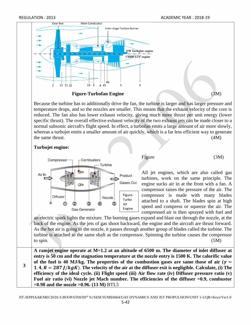
REGULATION : 2013 ACADEMIC YEAR : 2018-19
JIT-JEPPIAAR/MECH/Dr.S.BOOPATHI/IIIrd Yr/SEM 05/ME6604/GAS DYNAMICS AND JET PROPULSION/UNIT 1-5/QB+Keys/Ver1.0
5-42
Figure-Turbofan Engine (3M)
Because the turbine has to additionally drive the fan, the turbine is larger and has larger pressure and
temperature drops, and so the nozzles are smaller. This means that the exhaust velocity of the core is
reduced. The fan also has lower exhaust velocity, giving much more thrust per unit energy (lower
specific thrust). The overall effective exhaust velocity of the two exhaust jets can be made closer to a
normal subsonic aircraft's flight speed. In effect, a turbofan emits a large amount of air more slowly,
whereas a turbojet emits a smaller amount of air quickly, which is a far less efficient way to generate
the same thrust. (4M)
Turbojet engine:
Figure (3M)
All jet engines, which are also called gas
turbines, work on the same principle. The
engine sucks air in at the front with a fan. A
compressor raises the pressure of the air. The
compressor is made with many blades
attached to a shaft. The blades spin at high
speed and compress or squeeze the air. The
compressed air is then sprayed with fuel and
an electric spark lights the mixture. The burning gases expand and blast out through the nozzle, at the
back of the engine. As the jets of gas shoot backward, the engine and the aircraft are thrust forward.
As the hot air is going to the nozzle, it passes through another group of blades called the turbine. The
turbine is attached to the same shaft as the compressor. Spinning the turbine causes the compressor
to spin. (5M)
3
A ramjet engine operate at M=1.2 at an altitude of 6500 m. The diameter of inlet diffuser at
entry is 50 cm and the stagnation temperature at the nozzle entry is 1500 K. The calorific value
of the fuel is 40 MJ/kg. The properties of the combustion gases are same those of air (𝜸 =𝟏. 𝟒, 𝑹 = 𝟐𝟖𝟕 𝑱/𝒌𝒈𝑲). The velocity of the air at the diffuser exit is negligible. Calculate, (i) The
efficiency of the ideal cycle. (ii) Flight speed (iii) Air flow rate (iv) Diffuser pressure ratio (v)
Fuel air ratio (vi) Nozzle jet Mach number. The efficiencies of the diffuser =0.9, combustor
=0.98 and the nozzle =0.96. (13 M) BTL5
Figure- Turbo Jet Engine

REGULATION : 2013 ACADEMIC YEAR : 2018-19
JIT-JEPPIAAR/MECH/Dr.S.BOOPATHI/IIIrd Yr/SEM 05/ME6604/GAS DYNAMICS AND JET PROPULSION/UNIT 1-5/QB+Keys/Ver1.0
5-43
Answer: Refer Class notes
(i) The efficiency of the ideal cycle =22.3 % (3M)
(ii) Flight speed, 377.4 m/s (3M)
(iii) Air flow rate, 46.228 kg/s (2M)
(iv) Diffuser pressure ratio, 2.239 (2M)
(v) Fuel air ratio=0.0303 (2M)
(vi) Nozzle jet Mach number=1.110 (3M)
4
Calculate the thrust and specific thrust of a jet propulsion unit whose data are as follows: Total
head isentropic efficiency of the compressor= 80%, total head isentropic efficiency=85%, total
pressure ratio including combustor pressure loss = 4:1, Combustion efficiency =98 %,
Mechanical transmission efficiency=99%, Nozzle efficiency =90%, Maximum cycle
temperature=1000K, Air rate of flow =220 N/s, For air Cp=1005 J/kgK, 𝜸 = 𝟏. 𝟒, For gases
Cp=1153 J/kgK, 𝜸 = 𝟏. 𝟑, Ambient temperature and pressure are 15ºC and 1 bar. Neglect the
weight of fuel. (15 M) BTL5
Answer: Refer class notes
From Compressor efficiency T02=462.43 K (1M)
From Work input of the compressor T04 = 846.42 K (2M)
From Turbine efficiency P04=1.689 bar (3M)
From Exit velocity of the gas Cj= 447.40 m/s (3M)
Thrust of a jet propulsion =10.03 x 10³ N (3M)
Specific thrust of a jet propulsion=447.40 N/(kg/s) (3M)
`

REGULATION : 2013 ACADEMIC YEAR : 2018-19
JIT-JEPPIAAR/MECH/Dr.S.BOOPATHI/IIIrd Yr/SEM 05/ME6604/GAS DYNAMICS AND JET PROPULSION/UNIT 1-5/QB+Keys/Ver1.0
5-44
Subject Code : ME6604 Year/Semester : III/ 06
Subject Name : Gas Dynamics and Jet Propulsion Subject Handler : Dr. S. Boopathi
UNIT V SPACE PROPULSION
Types of rocket engines – Propellants-feeding systems – Ignition and combustion – Theory of rocket
propulsion – Performance study – Staging – Terminal and characteristic velocity – Applications – space
flights.
PART * A
Q.No. Questions
1.
What is bi-propellant? Give example. (Nov/Dec 2015) BTL2
If the fuel and oxidizer are different from each other in its chemical composition, then the propellant
is called bipropellant. Liquid Oxygen-Gasoline, Hydrogen peroxide-Hydrazine.
2
What is the role of inhibitors in rocket propulsion system? (Nov/Dec 2015) BTL3
They are used to regulate the burning of propellant.
Inhibitors or restrictors are used to regulate or prevent burning of the propellant grain or some
sections of its surface.
3
What is mono propellant? (April/May 2015) BTL2
A liquid propellant which contains both the fuel and oxidizer in a single chemical is known as
monopropellant.
4 Classify the rocket engines. (April/May 2015) BTL3
Chemical rocket engine, Solar rocket engine, nuclear rocket engine and Electrical rocket engine.
5
What are the properties of solid propellants? (Nov/Dec 2014) BTL2
It should have high density. It should not be poisonous and hazardous. It should be cheap and easily
available, storage and handling should be easy.
6 Define characteristic velocity. (Nov/Dec 2014) BTL4
C* = Cj/CF = Effective jet velocity / Thrust coefficient
7
Why rocket is called as non-air breathing engine? Can rocket work at vacuum? (May /June
2014) BTL5
Rocket engine carries its entire propellant (Oxidizer and Fuel) with it. Its performance does not
depend on atmospheric air like aircraft engines. Therefore they are called non-air breathing engines.
It can even work in vacuum.

REGULATION : 2013 ACADEMIC YEAR : 2018-19
JIT-JEPPIAAR/MECH/Dr.S.BOOPATHI/IIIrd Yr/SEM 05/ME6604/GAS DYNAMICS AND JET PROPULSION/UNIT 1-5/QB+Keys/Ver1.0
5-45
8 What is the use of inhibitors in solid propellants? (May /June 2014) BTL2
They are used to regulate the burning of propellant.
9
What is mono-propellant? Give example. (May /June 2013) BTL2
A liquid propellant which contains both the fuel and oxidizer in a single chemical is known as
monopropellant. Example: 1.Nitroglycerine 2.Nitromethane
10
What are the types of rocket engines based on source of energy employed? (May /June 2013)
BTL3
Chemical rocket engine, Solar rocket engine, nuclear rocket engine and Electrical rocket engine.
11
Give the classification of rockets on the basis of number of stages (ii) basis of size and range.
BTL4
i. On the basis of number of stages:
a. Single stage rockets.
b. Multi stage rockets.
ii. On the basis of size and range
a. Short range small rockets
b. Long range large rockets
12
What are the components of rocket engine? BTL2
a. Container
b. Combustion
c. Exhaust nozzle
d. Control & navigational equipment
e. Pay load.
13
Give some liquid fuels used in Rocket propulsion system. BTL4
The liquid fuels are:
1. Liquid hydrogen
2. Unsymmetrical dimethyl – hydrazine (UDMH).
3. Hydrazine
4. Alcohol.
14
List out some oxidizers used in liquid propellant rockets. BTL4
a. Liquid oxygen
b. Red fuming Nitric acid (RFNA).
c. Liquid fluorine
d. WFNA
15
List out the types of fuels and oxidizers used in solid propellant rockets. BTL4
Fuels – Plastic or resin material
Oxidizer – Nitrates, perchlorates.
16
Name some fuel – oxidizer combination for hybrid propellant rockets. BTL4
Beryllium hydride (Be – H2) – Flourine (F2)
Lithium hydride (LiH) – Clorine tri fluoride (Cl F3)
REGULATION : 2013 ACADEMIC YEAR : 2018-19
JIT-JEPPIAAR/MECH/Dr.S.BOOPATHI/IIIrd Yr/SEM 05/ME6604/GAS DYNAMICS AND JET PROPULSION/UNIT 1-5/QB+Keys/Ver1.0
5-46
Lithium Hydride (LiH) – nitrogen tetroxide (N2O4)
Hydro carbon (CH2) – Nitrogen tetroxide (N2O4)
17
Define Fin effectiveness. [Nov. ’96 M.U. Apr. 2001 M.U.] BTL2
Fin effectiveness is the ratio of heat transfer with fin to that without fin
Fin effectiveness =
with fin
without fin
Q
Q
18
Define hypergolic propellants. BTL2
For some combinations of fuels and oxidizer, ignition is not required to start the reaction;
merely the contact between the fuel and oxidizer starts the required reaction. Such propellants are
known as hypergolic propellants.
19
List out the main components of liquid propellant rocket engine. BTL4
The main components of liquid propellant rocket engine are:
i. Fuel and oxidizer tanks
ii. Gas pressure or turbo pump feed system
iii. Injectors
iv. Combustion chamber
v. Exhaust nozzle
20
Define cryogenic propellants. BTL2
The propellants which are in the gaseous state at normal temperature and require extremely
low temperature to maintain them in liquid state are known as cryogenic propellants.
21
List out some cryogenic propellants. BTL4
i. Liquid oxygen
ii.Hydrogen
iii. Flourine
iv. Ammonia
22
Define propellant grain. BTL1
A well – mixed fuel and oxidizer already present in thrust chamber is known as propellant grain.
23
List out the types of burning of solid propellants grain. BTL2
The types of burning of sold propellants are:
i. Regressive burning
ii. Neutral burning
iii. Progressive burning
REGULATION : 2013 ACADEMIC YEAR : 2018-19
JIT-JEPPIAAR/MECH/Dr.S.BOOPATHI/IIIrd Yr/SEM 05/ME6604/GAS DYNAMICS AND JET PROPULSION/UNIT 1-5/QB+Keys/Ver1.0
5-47
24
Distinguish between solid and liquid propellants. BTL5
S.No Solid Propellants Liquid Propellants
1. Solid propellants are generally stored in
combustion chamber.
Liquid propellants are stored in separate fuel tanks and
supplied to cc.
2. Solid propellants are burnt at
uncontrolled rate
Liquid propellant are burnt at controlled rate.
25
Define (i) Weight flow coefficient (ii) Thrust co-efficient. BTL5
(i) Weight flow co-efficient:
It is the ratio of gas or propellant flow rate and force. (P0A*)
Wp
Cw = ________
P0A*
ii. Thrust co-efficient: ratio of thrust and force (p0A*)
F
Cw = ________
P0A*
26
Define Impulse to weight ratio. BTL2
Impulse to weight ratio is the ratio of total impulse of the rocket to the total weight of rocket
vehicle system.
It
IWR = _____
Wt
27
Define characteristics velocity. BTL2
Characteristics velocity is defined as the ratio of effective jet velocity to thrust coefficient.
Effective jet velocity Cj
V* = __________________________ = _____
Thrust coefficient Cf
28
Define booster in rockets. BTL2
The First stage lifts off the entire rocket vehicle system is known as booster.
29 Define sounding rockets. BTL2
Rockets meant for taking instruments to high altitudes for meteorological measurement are

REGULATION : 2013 ACADEMIC YEAR : 2018-19
JIT-JEPPIAAR/MECH/Dr.S.BOOPATHI/IIIrd Yr/SEM 05/ME6604/GAS DYNAMICS AND JET PROPULSION/UNIT 1-5/QB+Keys/Ver1.0
5-48
called sounding rocket.
30
List out any 3 properties of good propellant. BTL4
i. It must have high calorific value.
ii. It must have high density
iii. It should be non – corrosive.
31
Name few merits of liquid propellants over solid propellants. BTL4
i. Liquid propellant engines can be reused after recovery.
ii. Higher values of specific impulse are obtained
iii. More flexible and greater control over the thrust.
iv. Easy to stop the operation in case of an impending catastrophe.
v. It is much easier to run an auxiliary power plant.
Part * B
1
A rocket nozzle has a throat area of 18 cm2 and combustor pressure of 25 bar. If the specific
impulse is 127.42 sec. and the rate of propellant is 44.145 N/s, determine the thrust coefficient,
propellant weight flow coefficient, specific propellant consumption and characteristic velocity.
(13 M) (May 2004) BTL5
Answer: Page 5.166- Dr.S.Senthil 2013
Specific impulse = 𝐼𝑠𝑝 =𝐹
�̇�𝑝𝑇ℎ𝑟𝑢𝑠𝑡 𝐹 = 5624.95 𝑁 (3M)
Thrust coefficient, 𝐶𝐹 =𝐹
𝑃0𝐴∗ = 1.25 (2M)
Propellant weight flow coefficient, 𝐶𝑤 =𝑊𝑃
𝑃0𝐴∗ = 9.81 𝑥 10−3 (2M)
Specific Propellant consumption = SPC = 𝑊𝑃
𝐹=
1
𝐼𝑆𝑃= 7.84 𝑥 10−3 𝑆−1 (2M)
Thrust F = �̇�𝑝𝐶𝑗 = 𝐶𝑗 = 1249.98𝑚
𝑠 (2M)
Characteristics velocity 𝐶∗ = 1000 𝑚/𝑠 (2M)
2
The specific impulse of a rocket is 125 s and the flow rate of propellant is 44 kg/s. The nozzle
throat area is 18 cm2 and the pressure in the combustion chamber is 25 bar. Determine the
throat coefficient, propellant flow coefficient, specific propellant consumption and
characteristic velocity. (13 M) (May 2005) BTL5
Answer: Page 5.172- Dr.S.Senthil 2013
Specific impulse = 𝐼𝑠𝑝 =𝐹
�̇�𝑝𝑇ℎ𝑟𝑢𝑠𝑡 𝐹 = 53950 𝑁 (2M)
REGULATION : 2013 ACADEMIC YEAR : 2018-19
JIT-JEPPIAAR/MECH/Dr.S.BOOPATHI/IIIrd Yr/SEM 05/ME6604/GAS DYNAMICS AND JET PROPULSION/UNIT 1-5/QB+Keys/Ver1.0
5-49
Thrust coefficient, 𝐶𝐹 =𝐹
𝑃0𝐴∗ = 11.99 (2M)
Propellant weight flow coefficient, 𝐶𝑤 =𝑊𝑃
𝑃0𝐴∗ = 95.92 𝑥 10−3 (2M)
Specific Propellant consumption = SPC = 𝑊𝑃
𝐹=
1
𝐼𝑆𝑃= 8 𝑥 10−3 𝑆−1 (3M)
Thrust F = �̇�𝑝𝐶𝑗 = 𝐶𝑗 = 1226.13𝑚
𝑠 (2M)
Characteristics velocity 𝐶∗ = 102.6 𝑚/𝑠 (2M)
3
In rocket engine, propellant flow rate is 5.2 kg/s, nozzle exit diameter is 9 cm, nozzle exit
pressure is 1.02 bar, atmospheric pressure is 1.013 bar, thrust chamber pressure is 22 bar and
thrust is 7.2 kN. Calculate the following (i) Effective jet velocity (ii) Actual jet velocity (iii)
Specific impulse (iv) Specific propellant consumption. (13 M)(Nov-Dec 2003) BTL5
Answer: Page 5.26- Dr.S.Senthil 2018.
Thrust F=�̇�𝑃 𝑥 𝐶𝑗 = ==> 𝐸𝑓𝑓𝑒𝑐𝑡𝑖𝑣𝑒 𝑗𝑒𝑡 𝑣𝑒𝑙𝑜𝑐𝑖𝑡𝑦 𝐶𝑗 = 1384.62 𝑚/𝑠 (3M)
Thrust F=�̇�𝑝𝐶𝑒 + (𝑃𝑒 − 𝑃𝑎)𝐴𝑒 Actual jet velocity 𝐶𝑒 = 1383.76 m/s (3M)
Specific impulse = 𝐼𝑠𝑝 =𝐹
�̇�𝑝𝑔= 141.14 𝑆 (3M)
Specific Propellant consumption = SPC = 𝑊𝑃
𝐹=
1
𝐼𝑆𝑃= 7.08 𝑥 10−3 𝑆−1 (4M)
4
A rocket flies at a speed of 10,000 kmph with an effective exhaust jet velocity of 1350 m/s and
the heat produced by the propellant is 6600 kJ/kg. If the propellant flow rate is 4.8 kg/s,
determine, (i) Propulsive efficiency (ii) Propulsive power (iii) Engine output (iv) Thermal
efficiency (v) Overall efficiency. (13 M) (May-June 2013) BTL5
Answer: Page 5.27- Dr.S.Senthil 2018
Rocket speed = 2777.7 m/s, C.V = 6600 x 103 J/kg (1M)
Speed ratio 𝜎 =𝑢
𝐶𝑗= 2.06 (1M)
Propulsive efficiency = ɳ𝑃 =2𝜎
1+𝜎2= 0.785 = 78.5% (1M)
Thrust F = �̇�𝑝𝐶𝑗= 6480 N (1M)
Propulsive power P= F x u = 17.9 x 10⁶ W (1M)
Propulsive efficiency ɳ𝑃 =𝑃𝑟𝑜𝑝𝑢𝑙𝑠𝑖𝑣𝑒 𝑝𝑜𝑤𝑒𝑟
𝑃𝑜𝑤𝑒𝑟 𝑜𝑢𝑡𝑝𝑢𝑡 𝑜𝑓 𝑡ℎ𝑒 𝑒𝑛𝑔𝑖𝑛𝑒 (2M)
𝑃𝑜𝑤𝑒𝑟 𝑜𝑢𝑡𝑝𝑢𝑡 𝑜𝑓 𝑡ℎ𝑒 𝑒𝑛𝑔𝑖𝑛𝑒 = 22.9 𝑥 106 𝑊 (2M)
REGULATION : 2013 ACADEMIC YEAR : 2018-19
JIT-JEPPIAAR/MECH/Dr.S.BOOPATHI/IIIrd Yr/SEM 05/ME6604/GAS DYNAMICS AND JET PROPULSION/UNIT 1-5/QB+Keys/Ver1.0
5-50
Thermal efficiency ɳ𝑡 =𝑃𝑜𝑤𝑒𝑟 𝑜𝑢𝑡𝑝𝑢𝑡 𝑜𝑓 𝑡ℎ𝑒 𝑒𝑛𝑔𝑖𝑛𝑒
𝑃𝑜𝑤𝑒𝑟 𝑖𝑛𝑝𝑢𝑡 𝑜𝑓 𝑡ℎ𝑒 𝑒𝑛𝑔𝑖𝑛𝑒 = 0.722= 72.2 % (2M)
Overall efficiency ɳ𝑂 = ɳ𝑡 𝑥ɳ𝑝 = 0.567 = 56.7 % (2M)
5
A rocket engine has the following data: Effective jet velocity =1200 m/s, Flight to jet speed ratio
= 0.82, Oxidizer flow rate = 3.4 kg/s, Fuel flow rate = 1.2 kg/s. Heat of reaction per kg of the
exhaust gases =2520 kJ/kg, Calculate the following, (i) Thrust (ii) Specific impulse (iii)
Propulsive efficiency (iv) Thermal efficiency (v) Overall efficiency. (13 M) (April-May 2015)
BTL5
Answer: Page 5.76- Dr.S.Senthil 2018
Propellant flow rate �̇�𝑃 = �̇�𝑂 + �̇�𝑓= 4.6 kg/s (1M)
Speed ratio 𝜎 =𝑢
𝐶𝑗= 2.06 Flight speed, u = 984 m/s, (2M)
Thrust F = �̇�𝑝𝐶𝑗= 5520 N (2M)
Specific impulse = 𝐼𝑠𝑝 =𝐹
�̇�𝑝𝑔= 122.32 𝑆 (2M)
Propulsive efficiency = ɳ𝑃 =2𝜎
1+𝜎2 = 0.98 = 98.0 % (2M)
Thermal efficiency ɳ𝑡 =𝐶𝑗
2+𝑢2
2 𝑥 𝐶𝑉= 0.477 = 47.7 % (2M)
Overall efficiency ɳ𝑂 = ɳ𝑡 𝑥ɳ𝑝 = 0.468 = 46.8 % (2M)
6
A rocket has the following data: Propellant flow rate = 5 kg/s, Nozzle exit diameter = 10 cm,
Nozzle exit pressure = 1.02 bar, Ambient pressure = 1.013 bar, Thrust chamber pressure = 20
bar, Thrust = 7 kN. Determine (i) Effective jet velocity (ii) Actual jet velocity (iii) Specific
impulse (iv) Specific propellant consumption. (13 M) (May-June 2016) (May-June 2012) (Nov-
Dec 2009) BTL5
Answer: Page 5.44- Dr.S.Senthil 2018
Thrust F=�̇�𝑃 𝑥 𝐶𝑗 = ==> 𝐸𝑓𝑓𝑒𝑐𝑡𝑖𝑣𝑒 𝑗𝑒𝑡 𝑣𝑒𝑙𝑜𝑐𝑖𝑡𝑦 𝐶𝑗 = 1400 𝑚/𝑠 (3M)
Thrust F=�̇�𝑝𝐶𝑒 + (𝑃𝑒 − 𝑃𝑎)𝐴𝑒 Actual jet velocity 𝐶𝑒 = 1399.9 m/s (4M)
Specific impulse = 𝐼𝑠𝑝 =𝐹
�̇�𝑝𝑔= 142.71 𝑆 (3M)
Specific Propellant consumption = SPC = 𝑊𝑃
𝐹=
1
𝐼𝑆𝑃= 7 𝑥 10−3 𝑆−1 (3M)
7
The effective jet velocity from a rocket is 2700 m/s. The forward flight velocity is 1350 m/s and
the propellant consumption is 78.6 kg/s, Calculate the thrust, thrust power, propulsive
efficiency. (13 M) (Nov 199) BTL5
REGULATION : 2013 ACADEMIC YEAR : 2018-19
JIT-JEPPIAAR/MECH/Dr.S.BOOPATHI/IIIrd Yr/SEM 05/ME6604/GAS DYNAMICS AND JET PROPULSION/UNIT 1-5/QB+Keys/Ver1.0
5-51
Answer: Page 5.50- Dr.S.Senthil 2018
Thrust F = �̇�𝑝𝐶𝑗= 212.22 N (3M)
Propulsive power P= F x u = 286.49 x 10⁶ W (3M)
Speed ratio 𝜎 =𝑢
𝐶𝑗= 2.06 𝜎 = 0.5 (3M)
Propulsive efficiency = ɳ𝑃 =2𝜎
1+𝜎2 = 0.80 = 80 % (4M)
8
A rocket engine has the following data: Effective jet velocity =1250 m/s, Flight to jet speed ratio
= 0.8, Oxidizer flow rate = 3.5 kg/s, Fuel flow rate = 1 kg/s. Heat of reaction per kg of the exhaust
gases =2500 kJ/kg, Calculate the following, (i) Thrust (ii) Specific impulse (iii) Propulsive
efficiency (iv) Thermal efficiency (v) Overall efficiency. (13 M) (April-May 2015) BTL5
Answer: Page 5.96- Dr.S.Senthil 2018
Propellant flow rate �̇�𝑃 = �̇�𝑂 + �̇�𝑓= 4.5 kg/s (1M)
Speed ratio 𝜎 =𝑢
𝐶𝑗= 0.8 Flight speed, u = 1000 m/s, (2M)
Thrust F = �̇�𝑝𝐶𝑗= 5625 N (2M)
Specific impulse = 𝐼𝑠𝑝 =𝐹
�̇�𝑝𝑔= 127.42 𝑆 (2M)
Propulsive efficiency = ɳ𝑃 =2𝜎
1+𝜎2 = 0.975 = 97.5 % (2M)
Thermal efficiency ɳ𝑡 =𝐶𝑗
2+𝑢2
2 𝑥 𝐶𝑉= 0.5125 = 51.25 % (2M)
Overall efficiency ɳ𝑂 = ɳ𝑡 𝑥ɳ𝑝 = 0.499 = 49.9 % (2M)
9
Determine the escape and orbital velocities of a rocket for the given conditions. (a) at mean sea
level (b) at an altitude 650 km. Take radius of earth at mean sea level is 6341.6 km. Acceleration
due to gravity at mean sea level =9.809 m/s2. (13 M) (May-June 2013) BTL5
Answer: Page 5.106- Dr.S.Senthil 2018
At, Z=0, 𝑈𝑜𝑟𝑏 = √𝑔0𝑅0 =7887 m/s (4M)
𝑈𝑒𝑠𝑐 = √2 𝑈𝑜𝑟𝑏 = 11153.902 𝑚/𝑠 (3M)
At, Z=650, 𝑈𝑜𝑟𝑏 = 𝑅0√𝑔0
𝑅0+𝑍 =7511.435 m/s (3M)
𝑈𝑒𝑠𝑐 = √2 𝑈𝑜𝑟𝑏 = 10622.773 𝑚/𝑠 (3M)
Part *C
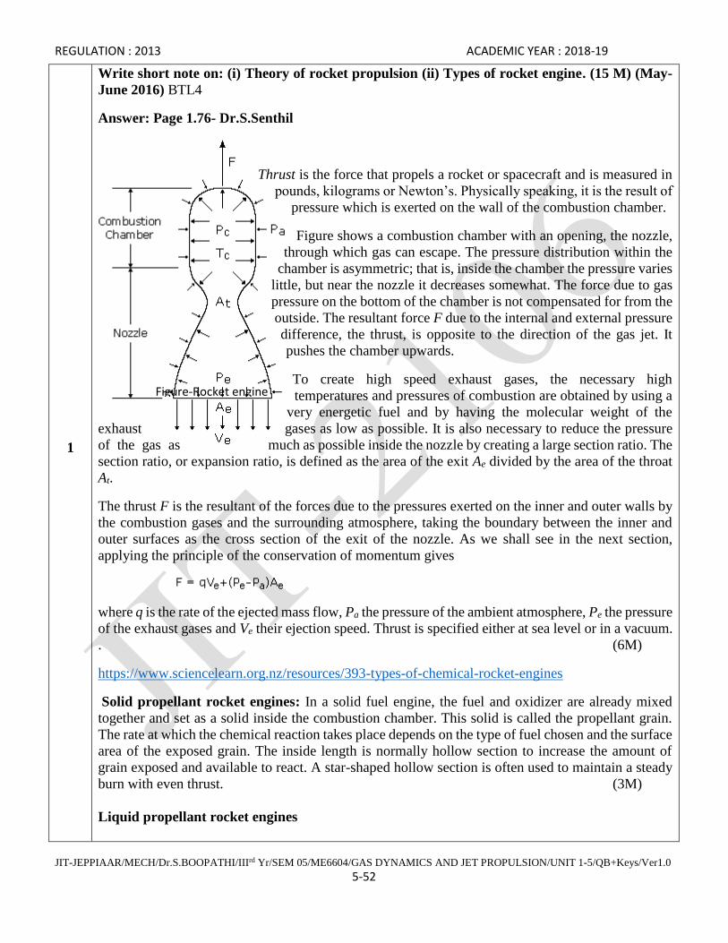
REGULATION : 2013 ACADEMIC YEAR : 2018-19
JIT-JEPPIAAR/MECH/Dr.S.BOOPATHI/IIIrd Yr/SEM 05/ME6604/GAS DYNAMICS AND JET PROPULSION/UNIT 1-5/QB+Keys/Ver1.0
5-52
1
Write short note on: (i) Theory of rocket propulsion (ii) Types of rocket engine. (15 M) (May-
June 2016) BTL4
Answer: Page 1.76- Dr.S.Senthil
Thrust is the force that propels a rocket or spacecraft and is measured in
pounds, kilograms or Newton’s. Physically speaking, it is the result of
pressure which is exerted on the wall of the combustion chamber.
Figure shows a combustion chamber with an opening, the nozzle,
through which gas can escape. The pressure distribution within the
chamber is asymmetric; that is, inside the chamber the pressure varies
little, but near the nozzle it decreases somewhat. The force due to gas
pressure on the bottom of the chamber is not compensated for from the
outside. The resultant force F due to the internal and external pressure
difference, the thrust, is opposite to the direction of the gas jet. It
pushes the chamber upwards.
To create high speed exhaust gases, the necessary high
temperatures and pressures of combustion are obtained by using a
very energetic fuel and by having the molecular weight of the
exhaust gases as low as possible. It is also necessary to reduce the pressure
of the gas as much as possible inside the nozzle by creating a large section ratio. The
section ratio, or expansion ratio, is defined as the area of the exit Ae divided by the area of the throat
At.
The thrust F is the resultant of the forces due to the pressures exerted on the inner and outer walls by
the combustion gases and the surrounding atmosphere, taking the boundary between the inner and
outer surfaces as the cross section of the exit of the nozzle. As we shall see in the next section,
applying the principle of the conservation of momentum gives
where q is the rate of the ejected mass flow, Pa the pressure of the ambient atmosphere, Pe the pressure
of the exhaust gases and Ve their ejection speed. Thrust is specified either at sea level or in a vacuum.
. (6M)
https://www.sciencelearn.org.nz/resources/393-types-of-chemical-rocket-engines
Solid propellant rocket engines: In a solid fuel engine, the fuel and oxidizer are already mixed
together and set as a solid inside the combustion chamber. This solid is called the propellant grain.
The rate at which the chemical reaction takes place depends on the type of fuel chosen and the surface
area of the exposed grain. The inside length is normally hollow section to increase the amount of
grain exposed and available to react. A star-shaped hollow section is often used to maintain a steady
burn with even thrust. (3M)
Liquid propellant rocket engines
Figure-Rocket engine
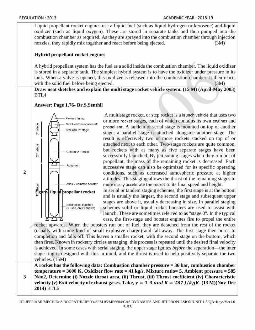
REGULATION : 2013 ACADEMIC YEAR : 2018-19
JIT-JEPPIAAR/MECH/Dr.S.BOOPATHI/IIIrd Yr/SEM 05/ME6604/GAS DYNAMICS AND JET PROPULSION/UNIT 1-5/QB+Keys/Ver1.0
5-53
Liquid propellant rocket engines use a liquid fuel (such as liquid hydrogen or kerosene) and liquid
oxidizer (such as liquid oxygen). These are stored in separate tanks and then pumped into the
combustion chamber as required. As they are sprayed into the combustion chamber through injection
nozzles, they rapidly mix together and react before being ejected. (3M)
Hybrid propellant rocket engines
A hybrid propellant system has the fuel as a solid inside the combustion chamber. The liquid oxidizer
is stored in a separate tank. The simplest hybrid system is to have the oxidizer under pressure in its
tank. When a valve is opened, this oxidizer is released into the combustion chamber. It then reacts
with the solid fuel before being ejected. (3M)
2
Draw neat sketches and explain the multi stage rocket vehicle system. (15 M) (April-May 2003)
BTL4
Answer: Page 1.76- Dr.S.Senthil
A multistage rocket, or step rocket is a launch vehicle that uses two
or more rocket stages, each of which contains its own engines and
propellant. A tandem or serial stage is mounted on top of another
stage; a parallel stage is attached alongside another stage. The
result is effectively two or more rockets stacked on top of or
attached next to each other. Two-stage rockets are quite common,
but rockets with as many as five separate stages have been
successfully launched. By jettisoning stages when they run out of
propellant, the mass of the remaining rocket is decreased. Each
successive stage can also be optimized for its specific operating
conditions, such as decreased atmospheric pressure at higher
altitudes. This staging allows the thrust of the remaining stages to
more easily accelerate the rocket to its final speed and height.
In serial or tandem staging schemes, the first stage is at the bottom
and is usually the largest, the second stage and subsequent upper
stages are above it, usually decreasing in size. In parallel staging
schemes solid or liquid rocket boosters are used to assist with
launch. These are sometimes referred to as "stage 0". In the typical
case, the first-stage and booster engines fire to propel the entire
rocket upwards. When the boosters run out of fuel, they are detached from the rest of the rocket
(usually with some kind of small explosive charge) and fall away. The first stage then burns to
completion and falls off. This leaves a smaller rocket, with the second stage on the bottom, which
then fires. Known in rocketry circles as staging, this process is repeated until the desired final velocity
is achieved. In some cases with serial staging, the upper stage ignites before the separation—the inter
stage ring is designed with this in mind, and the thrust is used to help positively separate the two
vehicles. (15M)
3
A rocket has the following data: Combustion chamber pressure = 36 bar, combustion chamber
temperature = 3600 K, Oxidizer flow rate = 41 kg/s, Mixture ratio= 5, Ambient pressure = 585
N/m2, Determine (i) Nozzle throat area, (ii) Thrust, (iii) Thrust coefficient (iv) Characteristic
velocity (v) Exit velocity of exhaust gases. Take, 𝜸 = 𝟏. 𝟑 𝒂𝒏𝒅 𝑹 = 𝟐𝟖𝟕 𝑱/𝒌𝒈𝑲. (13 M)(Nov-Dec
2014) BTL6
Figure- Liquid propellant rocket
engine

REGULATION : 2013 ACADEMIC YEAR : 2018-19
JIT-JEPPIAAR/MECH/Dr.S.BOOPATHI/IIIrd Yr/SEM 05/ME6604/GAS DYNAMICS AND JET PROPULSION/UNIT 1-5/QB+Keys/Ver1.0
5-54
Answer: Page 5.39- Dr.S.Senthil 2018
(i) Nozzle throat area , A*= 0.0129 m2 (3M)
(ii) Thrust, F=137.68 x 10³ N (3M)
(iii) Thrust coefficient, 𝐶𝐹 = 2.96 (3M)
(iv) Characteristic velocity, C*= 945.45 m/s (3M)
(v) Exit velocity of exhaust gases, Ce= 2798.56 m/s (3M)
4
With the help of neat sketches explain any two arrangements used for fuel feeding in liquid
propellant rocket systems. (15 M) (April-May 2011) BTL4
Answer: Page 1.76- Dr.S.Senthil
Figure (5M)
The common liquid rocket is bipropellant; it
uses two separate propellants, a liquid fuel and
liquid oxidizer. These are contained in separate
tanks and are mixed only upon injection into
the combustion chamber. They may be fed to
the combustion chamber by pumps or by
pressure in the tanks Propellant flow rates must
be extremely large for high-thrust engines,
often hundreds of gallons per second. Pump-
fed systems may require engines delivering
several thousand horsepower to drive the
pumps.4 This power is usually developed by a
hot gas turbine, supplied from a gas generator
which is actually a small combustion chamber.
The main rocket propellants can be used for the gas generator. (10M)
5
Describe with a schematic diagram the principle of working of a liquid propellant rocket. (15
M) (April-May 2011) BTL4
Answer: Page 1.76- Dr.S.Senthil
Figure - liquid propellant rocket (5M)
A liquid-propellant rocket or liquid rocket is a rocket engine that uses liquid propellants. Liquids are
desirable because their reasonably high density allows the volume of the propellant tanks to be

REGULATION : 2013 ACADEMIC YEAR : 2018-19
JIT-JEPPIAAR/MECH/Dr.S.BOOPATHI/IIIrd Yr/SEM 05/ME6604/GAS DYNAMICS AND JET PROPULSION/UNIT 1-5/QB+Keys/Ver1.0
5-55
relatively low, and it is possible to use lightweight centrifugal turbo pumps to pump the propellant
from the tanks into the combustion chamber, which means that the propellants can be kept under low
pressure. This permits the use of low-mass propellant tanks, resulting in a high mass ratio for the
rocket. (5M)
An inert gas stored in a tank at a high pressure is sometimes used instead of pumps in simpler small
engines to force the propellants into the combustion chamber. These engines may have a lower mass
ratio, but are usually more reliable, and are therefore used widely in satellites for orbit maintenance.
Liquid rockets can be monopropellant rockets using a single type of propellant, bipropellant rockets
using two types of propellant, or more exotic tri propellant rockets using three types of propellant.
Some designs are throttle able for variable thrust operation and some may be restarted after a previous
in-space shutdown. Liquid propellants are also used in hybrid rockets, in which a liquid oxidizer is
generally combined with a solid fuel. (5M)