me5202 - arun mujumdar
TRANSCRIPT
Arun S. Mujumdar
ME5202
Dept. of Mechanical Engineering
National University of Singapore
2011/20
12

ME5202
Arun S. Mujumdar
Department of Mechanical Engineering
National University of Singapore
AY 2011/2012

CONTENTS

CHAPTER
ONE FUNDAMENTAL PRINCIPLES OF DRYING
Arun S. Mujumdar and Sakamon Devahastin
1. INTRODUCTION
The separation operation of drying converts a solid, semi-solid or liquid feedstock into a solid product by evaporation of the liquid into a vapor phase via application of heat. In the special case of freeze drying, which takes place below the triple point of the liquid being removed, drying occurs by sublimation of the solid phase directly into the vapor phase. This definition thus excludes conversion of a liquid phase into a concentrated liquid phase (evaporation), mechanical dewatering operations such as filtration, centrifugation, sedimentation, supercritical extraction of water from gels to produce extremely high porosity aerogels (extraction) or so-called drying of liquids and gases by use of molecular sieves (adsorption). Phase change and production of a solid phase as end product are essential features of the drying process. Drying is an essential operation in the chemical, agricultural, biotechnology, food, polymer, ceramics, pharmaceutical, pulp and paper, mineral processing, and wood processing industries.
Drying is perhaps the oldest, most common and most diverse of chemical engineering unit operations. Over four hundred types of dryers have been reported in the literature while over one hundred distinct types are commonly available. It competes with distillation as the most energy-intensive unit operation due to the high latent heat of vaporization and the inherent inefficiency of using hot air as the (most common) drying medium. Various studies report national energy consumption for industrial drying operations ranging from 10-15% for USA, Canada, France, and UK to 20-25% for Denmark and Germany. The latter figures have been obtained recently based on mandatory energy audit data supplied by industry and hence are more reliable.

FUNDAMENTAL PRINCIPLES OF DRYING ___________________________________________
2
Energy consumption in drying ranges from a low value of under five percent for the chemical process industries to thirty five percent for the papermaking operations. In the USA, for example, capital expenditures for dryers are estimated to be in the order of only $800 million per annum. Thus, the major costs for dryers are in their operation rather than in their initial investment costs.
Drying of various feedstocks is needed for one or several of the following reasons: need for easy-to-handle free-flowing solids, preservation and storage, reduction in cost of transportation, achieving desired quality of product, etc. In many processes, improper drying may lead to irreversible damage to product quality and hence a non-salable product.
Before proceeding to the basic principles, it is useful to note the following unique features of drying which make it a fascinating and challenging area for R&D:
Product size may range from microns to tens of centimeters (in thickness or
depth) Product porosity may range from zero to 99.9 percent Drying times range from 0.25 sec (drying of tissue paper) to five months (for
certain hardwood species) Production capacities may range from 0.10 kg/h to 100 t/h Product speeds range from zero (stationary) to 2000 m/s (tissue paper) Drying temperatures range from below the triple point to above the critical
point of the liquid Operating pressure may range from fraction of a millibar to 25 atmospheres Heat may be transferred continuously or intermittently by convection,
conduction, radiation or electromagnetic fields
Clearly, no single design procedure that can apply to all or even several of the dryer variants is possible. It is therefore essential to revert to the fundamentals of heat, mass and momentum transfer coupled with a knowledge of the material properties (quality) when attempting design of a dryer or analysis of an existing dryer. Mathematically speaking, all processes involved, even in the simplest dryer, are highly nonlinear and hence scale-up of dryers is generally very difficult. Experimentation at laboratory and pilot scales coupled with field experience and know-how is essential to the development of a new dryer application. Dryer vendors are necessarily specialized and normally offer only a narrow range of drying equipment. The buyer must therefore be reasonably conversant with the basic knowledge of the wide assortment of dryers and be able to come up with an informal preliminary selection before going to the vendors with notable exceptions. In general, several different dryers may be able to handle a given application. 2. BASIC PRINCIPLES AND TERMINOLOGY
Drying is a complex operation involving transient transfer of heat and mass along
with several rate processes, such as physical or chemical transformations, which, in turn,

FUNDAMENTAL PRINCIPLES OF DRYING ___________________________________________
3
may cause changes in product quality as well as the mechanisms of heat and mass transfer. Physical changes that may occur include: shrinkage, puffing, crystallization, glass transitions. In some cases, desirable or undesirable chemical or biochemical reactions may occur leading to changes in color, texture, odor or other properties of the solid product. In the manufacture of catalysts, for example, drying conditions can yield significant differences in the activity of the catalyst by changing the internal surface area.
Drying occurs by effecting vaporization of the liquid by supplying heat to the wet feedstock. As noted earlier, heat may be supplied by convection (direct dryers), by conduction (contact or indirect dryers), radiation or volumetrically by placing the wet material in a microwave or radio frequency electromagnetic field. Over 85 percent of industrial dryers are of the convective type with hot air or direct combustion gases as the drying medium. Over 99 percent of the applications involve removal of water. All modes except the dielectric (microwave and radio frequency) supply heat at the boundaries of the drying object so that the heat must diffuse into the solid primarily by conduction. The liquid must travel to the boundary of the material before it is transported away by the carrier gas (or by application of vacuum for non-convective dryers).
Transport of moisture within the solid may occur by any one or more of the following mechanisms of mass transfer:
Liquid diffusion, if the wet solid is at a temperature below the boiling point of
the liquid Vapor diffusion, if the liquid vaporizes within material Knudsen diffusion, if drying takes place at very low temperatures and
pressures, e.g., in freeze drying Surface diffusion (possible although not proven) Hydrostatic pressure differences, when internal vaporization rates exceed the
rate of vapor transport through the solid to the surroundings Combinations of the above mechanisms
Note that since the physical structure of the drying solid is subject to change
during drying the mechanisms of moisture transfer may also change with elapsed time of drying. 2.1 Thermodynamic Properties of Air-Water Mixtures and Moist Solids 2.1.1 Psychrometry As noted earlier, a majority of dryers are of direct (or convective) type. In other words, hot air is used both to supply the heat for evaporation and to carry away the evaporated moisture from the product. Notable exceptions are freeze and vacuum dryers, which are used almost exclusively for drying heat-sensitive products because they tend to be significantly more expensive than dryers operate near to atmospheric pressure. Another exception is the emerging technology of superheated steam drying (Mujumdar, 1995). In certain cases, such as the drum drying of pasty foods, some or all of the heat is supplied indirectly by conduction.
FUNDAMENTAL PRINCIPLES OF DRYING ___________________________________________
4
Drying with heated air implies humidification and cooling of the air in a well-insulated (adiabatic) dryer. Thus, hygrothermal properties of humid air are required for the design calculations of such dryers. Table 1 summarizes the essential thermodynamic and transport properties of the air-water system. In Table 2, a listing of brief definitions of various terms encountered in drying and psychrometry is given. It also includes several terms not explicitly discussed in the text. Table 1 Thermodynamic and transport properties of air-water system (Mujumdar, 1995; Pakowski et al., 1991) Property Expression Pv P T Tv abs abs 100 270214 6887 532 27316exp[ . ( / ) . ln( / . )] Y Y RH P P RH Pv v 0 622. / ( ) cpg c T T Tpg 100926 10 4 0403 10 61759 10 4 097 103 2 4 2 7 3. . . . kg k T T Tg 2 425 10 7 889 10 1790 10 8 570 102 5 8 2 12 3. . . . g g g absPM RT / ( ) g g T T T 1691 10 4 984 10 3187 10 1319 105 8 11 2 14 3. . . . cpv c T T Tpv 1883 16737 10 8 4386 10 2 6966 104 7 2 10 3. . . . cpw c T T Tpw 2 8223 11828 10 35043 10 3601 102 5 2 8 3. . . .
Figure 1 is a psychrometric chart for the air-water system. It shows the relationship between the temperature (abscissa) and absolute humidity (ordinate, in kg water per kg dry air) of humid air at one atmosphere absolute pressure over 0o to 130o C. Line representing percent humidity and adiabatic saturation are drawn according to the thermodynamic definitions of these terms. Equations for the adiabatic saturation and wet-bulb temperature lines on the chart are as follows (Geankoplis, 1993):
Y YT T
c Yas
as
s
as as
1005 188. . (1)
and
Y YT T
h M kwb
wb
air y
wb
/
(2)
The ratio (h/Mairky), the psychrometric ratio, lies between 0.96 - 1.005 for air-water vapor mixtures; thus it is nearly equal to the value of humid heat cs. If the effect of humidity is neglected, the adiabatic saturation and wet-bulb temperatures (Tas and Twb, respectively) are almost equal for the air-water system. Note, however, that Tas and Tw are conceptually quite different. The adiabatic saturation temperature is a gas temperature and a thermodynamic entity while the wet-bulb temperature is a heat and mass transfer rate-based entity and refers to the temperature of the liquid phase. Under constant drying conditions, the surface of the drying material attains the wet-bulb temperature if heat transfer is by pure convection. The wet-bulb temperature is independent of surface geometry as a result of the analogy between heat and mass transfer.

FUNDAMENTAL PRINCIPLES OF DRYING ___________________________________________
5
Table 2 Definitions of commonly encountered terms in psychrometry and drying Term/symbol Meaning Adiabatic saturation
temperature, Tas Equilibrium gas temperature reached by unsaturated gas and vaporizing liquid under adiabatic conditions.
(Note: For air/water system only, it is equal to the wet bulb temperature (Twb))
Bound moisture Liquid physically and/or chemically bound to solid matrix so as to exert a vapor pressure lower than that of pure liquid at the same temperature
Constant rate drying period
Under constant drying conditions, drying period when evaporation rate per unit drying area is constant (when surface moisture is removed)
Dew point Temperature at which a given unsaturated air-vapor mixture becomes saturated
Dry bulb temperature Temperature measured by a (dry) thermometer immersed in vapor-gas mixture
Equilibrium moisture content, X*
At a given temperature and pressure, the moisture content of moist solid in equilibrium with the gas-vapor mixture (zero for non-hygroscopic solids)
Critical moisture content, Xc
Moisture content at which the drying rate first begins to drop (under constant drying conditions)
Falling rate period Drying period (under constant drying conditions) during which the rate falls continuously in time
Free moisture, Xf Xf = X = X*
Moisture content in excess of the equilibrium moisture content (hence free to be removed) at given air humidity and temperature
Humid heat Heat required to raise the temperature of unit mass of dry air and its associated vapor through one degree (J kg-1 K-1 or Btu lb-1 oF-
1)
Humidity, absolute Mass of water vapor per unit mass of dry gas (kg kg-1 or lb lb-1)
Humidity, relative Ratio of partial pressure of water vapor in gas-vapor mixture to equilibrium vapor pressure at the same temperature
Unbound moisture Moisture in solid which exerts vapor pressure equal to that of pure liquid at the same temperature
Water activity, aw Ratio of vapor pressure exerted by water in solid to that of pure water at the same temperature
Wet bulb tempera- Liquid temperature attained when large amounts of air-vapor
FUNDAMENTAL PRINCIPLES OF DRYING ___________________________________________
6
ture, Twb mixture is contacted with the surface. In purely convective drying, drying surface reaches Twb during the constant rate period
Figure 1 Psychrometric chart for the air-water system
Most handbooks of engineering provide more detailed psychrometric charts including additional information and extended temperature ranges. Mujumdar (1995) includes numerous psychrometric charts for several gas-organic vapor systems as well. 2.1.2 Equilibrium Moisture Content The moisture content of a wet solid in equilibrium with air of given humidity and temperature is termed the equilibrium moisture content (EMC). A plot of EMC at a given temperature versus the relative humidity is termed sorption isotherm. An isotherm obtained by exposing the solid to air of increasing humidity gives the adsorption isotherm. That obtained by exposing the solid to air of decreasing humidity is known as the desorption isotherm. Clearly, the latter is of interest in drying as the moisture content of the solids progressively decreases. Most drying materials display “hysteresis” in that the two isotherms are not identical.

FUNDAMENTAL PRINCIPLES OF DRYING ___________________________________________
7
Figure 2 shows the general shape of the typical sorption isotherms. They are characterized by three distinct zones, A, B and C, which are indicative of different water binding mechanisms at individual sites on the solid matrix. In region A, water is tightly bound to the sites and is unavailable for reaction. In this region, there is essentially monolayer adsorption of water vapor and no distinction exists between the adsorption and desorption isotherms. In region B, the water is more loosely bound. The vapor pressure depression below the equilibrium vapor pressure of water at the same temperature is due to its confinement in smaller capillaries. Water in region C is even more loosely held in larger capillaries. It is available for reactions and as a solvent.
20 40 60 80 100
A
B
C
Adsorption
Desorption
Mo
istu
re c
on
ten
t
Relative humidity (%)
0
Figure 2 Typical sorption isotherms Numerous hypotheses have been proposed to explain the hysteresis. The reader is referred elsewhere (Bruin and Luyben, 1980; Fortes and Okos, 1980; Bruin, 1988) for more information on the topic. Figure 3 shows schematically the shapes of the equilibrium moisture curves for various types of solids. Figure 4 shows the various types of moisture defined in Table 2. Desorption isotherms are also dependent on external pressure. However, in all practical cases of interest, this effect may be neglected.

FUNDAMENTAL PRINCIPLES OF DRYING ___________________________________________
8
0
100
X, kg water / kg dry solid
Relativehumidity
Non-hygroscopic
Nearlynon-hygroscopic
Hygroscopicporous
Colloidal
Colloidal, infinitely swelling
T = CONST.
Figure 3 Equilibrium moisture content curves for various types of solids
MOISTURE CONTENT, X
R.H.
0 0
1.0
T = CONST.
0.5
X , Equilibrium moisture content *
bound moisture
unbound moisture
free moisture
Figure 4 Various types of moisture content
According to Keey (1978), the temperature dependence of the equilibrium moisture content can be correlated by:
XT
Xcons t
*
tan
*
(3)
where X* is the dry-basis equilibrium moisture content, T is the temperature and is the relative humidity of air. The parameter ranges from 0.005 to 0.01 K-1. This correlation may be used to estimate the temperature dependence of X* if no data are available. For hygroscopic solids, the enthalpy of the attached moisture is less than that of pure liquid by an amount equal to the binding energy, which is also termed the enthalpy of

FUNDAMENTAL PRINCIPLES OF DRYING ___________________________________________
9
wetting, Hw (Keey, 1978). It includes the heat of sorption, hydration and solution and may be estimated from the following equation:
dd T
HR TX cons t
w
g
(ln )( / ) tan
1
(4)
A plot of ln( ) against 1/T is linear with a slope of Hw/Rg where Rg is the universal gas constant (Rg = 8.314 103 kg kgmol-1 K-1). Note that the total heat required to evaporate bound water is the sum of the latent heat of vaporization and the heat of wetting; the latter is a function of the moisture content X. The heat of wetting is zero for unbound water and increases with decreasing X. Since Hw is responsible for lowering the vapor pressure of bound water, at the same relative humidity, Hw is almost the same for all materials (Keey, 1978). For most materials, the moisture binding energy is positive; generally it is a monotonically decreasing function of the moisture content, with a value of zero for unbound moisture. For hydrophobic food materials (e.g., peanut oil, starches at lower temperatures) the binding energy can, however, be negative. In general, water sorption data must be determined experimentally. Some 80 correlations, ranging from those based on theory to those that are purely empirical, have appeared in the literature. Two of the most extensive compilations are due to Wolf et al. (1985) and Iglesias and Chirife (1982). Aside from temperature, the physical structure as well as composition of the material also affect water sorption. The pore structure and size as well as physical and/or chemical transformations during drying can cause significant variations in the moisture binding ability of the solid. 2.1.3 Water Activity
In drying of some materials, which require careful hygienic attention, e.g., food, the availability of water for growth of microorganisms, germination of spores, and participation in several types of chemical reaction becomes an important issue. This availability, which depends on relative pressure, or water activity, aw, is defined as the ratio of the partial pressure, p, of water over the wet solid system to the equilibrium vapor pressure, pw, of water at the same temperature. Thus, aw, which is also equal to the relative humidity of the surrounding humid air, is defined as:
ap
pww
(5)
Different shapes of the X versus aw curves are observed, depending on the type of material (e.g., high, medium or low hygroscopicity solids). Table 3 lists the measured minimum aw values for microbial growth or spore germination. If aw is reduced below these values by dehydration or by adding water-binding agents like sugars, glycerol, or salt, microbial growth is inhibited. Such additives should not affect the flavor, taste, or other quality criteria, however. Since the amounts of soluble additives needed to depress aw even by 0.1 is quite large, dehydration becomes particularly attractive for high moisture foods as a way to reduce aw. Figure 5 shows schematically the

FUNDAMENTAL PRINCIPLES OF DRYING ___________________________________________
10
water activity versus moisture content curve for different types of food. Rockland and Beuchat (1987) provide an extensive compilation of results on water activity and its applications. Table 3 Minimum water activity, aw, for microbial growth and spore germination (adapted from Brockmann, 1973) Micro-organism Water activity Organisms producing slime on meat 0.98
Pseudomonas, Bacillus cereus spores 0.97
B. subtilis, C. botulinum spores 0.95
C. botulinum, Salmonella 0.93
Most bacteria 0.91
Most yeast 0.88
Aspergillus niger 0.85
Most molds 0.80
Halophilic bacteria 0.75
Xerophilic fungi 0.65
Osmophilic yeast 0.62

FUNDAMENTAL PRINCIPLES OF DRYING ___________________________________________
11
Dry foods
Intermediate moisture foods (IMF) e.g. syrups
cheese, sausages, candy
a w
Dry basis water content
0 0 1.0 2.0 3.0
0.1
0.2
0.3
0.4
0.5
0.6
0.7
0.8
0.9
1.0
Figure 5 Water activity versus moisture content plot for different types of food
Figure 6 shows the general nature of the deterioration reaction rates as a function of aw for food systems. Aside from microbial damage, which typically occurs for aw > 0.70, oxidation, non-enzymatic browning (Maillard reactions) and enzymatic reactions can occur even at very low aw levels during drying. Laboratory or pilot testing is essential to ascertain that no damage occurs in the selected drying process since this cannot, in general, be predicted.

FUNDAMENTAL PRINCIPLES OF DRYING ___________________________________________
12
Lipid oxidation
Browning reaction
Moisture isotherm
Enzymes MoldsYea
st
Bacte
ria
Relative activity
Water activity, aw
0
10010 20 30 40 50 60 70 80 900
Figure 6 Deterioration rates as a function of water activity for food systems 2.2 Drying Kinetics Consider the drying of a wet solid under fixed drying conditions. In the most general cases, after an initial period of adjustment, the dry-basis moisture content, X, decreases linearly with time, t, following the start of the evaporation. This is followed by a non-linear decrease in X with t until, after a very long time, the solid reaches its equilibrium moisture content, X* and drying stops. In terms of free moisture content, defined as: X X Xf ( )* (6) the drying rate drop to zero at Xf = 0. By convention, the drying rate, N, is defined as:
NMA
dXdt
orMA
dXdt
s s f (7)
under constant drying conditions. Here, N (kg m-2 h-1) is the rate of water evaporation, A is the evaporation area (may be different from heat transfer area) and Ms is the mass of bone dry solid. If A is not known, then the drying rate may be expressed in kg water evaporated per hour.

FUNDAMENTAL PRINCIPLES OF DRYING ___________________________________________
13
A plot of N versus X (or Xf) is the so-called drying rate curve. This curve must always be obtained under constant drying conditions. Note that, in actual dryers, the drying material is generally exposed to varying drying conditions (e.g., different relative gas-solid velocities, different gas temperatures and humidities, different flow orientations). Thus, it is necessary to develop a methodology in order to interpolate or extrapolate limited drying rate data over a range of operating conditions. Figure 7 shows a typical “textbook” drying rate curve displaying an initial constant rate period where N = Nc = constant. The constant rate period is governed fully by the rates of external heat and mass transfer since a film of free water is always available at the evaporating surface. This drying period is nearly independent of the material being dried. Many foods and agricultural products, however, do not display the constant rate period at all since internal heat and mass transfer rates determine the rate at which water becomes available at the exposed evaporating surface.
X* Xc
X, Moisture content, kg water/kg dry solid
Initial
transient
Constant rate dryingFalling rate period
(External heat/mass
transfer rate controlling)
(Internal heat/mass
transfer rate controlling)
Surface w et particle
Par
ticl
e su
rfac
e
par
tial
ly w
et
Par
ticl
e
surf
ace
dry
R, Drying rate,
kg/h m 2
Figure 7 Typical textbook batch drying rate curve under
constant drying conditions
At the so-called critical moisture content, Xc, N begins to fall with further decrease in X since water cannot migrate at the rate Nc to the surface due to internal transport limitations. The mechanism underlying this phenomenon depends on both the material and drying conditions. The drying surface becomes first partially unsaturated and then fully unsaturated until it reaches the equilibrium moisture content X*. Detailed discussions of drying rate curves are given by Keey (1991), Mujumdar and Menon (1995). Approximate critical moisture content values for some selected materials are given in Table 4. Note that a material may display more than one critical moisture contents at which the drying rate curve shows a sharp change of shape. This is generally associated with changes in the underlying mechanisms of drying due to structural or chemical changes. It is

FUNDAMENTAL PRINCIPLES OF DRYING ___________________________________________
14
also important to note that Xc is not solely a material property. It depends on the drying rate under otherwise similar conditions. It must be determined experimentally. Table 4 Approximate critical moisture contents for various materials Material Critical moisture content
(kg water/kg dry solid) Salt crystals, rock salt, sand, wool 0.05-0.10 Brick clay, kaolin, crushed sand 0.10-0.20 Pigments, paper, soil, worsted wool fabric 0.20-0.40 Several foods, copper carbonate, sludges 0.40-0.80 Chrome leather, vegetables, fruits, gelatin, gels > 0.80 It is easy to see that Nc can be calculated using empirical or analytical techniques to estimate the external heat/mass transfer rates (Keey, 1978; Geankoplis, 1993). Thus,
Nq
cs
(8)
where q represents the sum of heat fluxes due to convection, conduction and/or radiation and s is the latent heat of vaporization at the solid temperature. In the case of purely convective drying, the drying surface is always saturated with water in the constant rate period and thus the liquid film attains the wet-bulb temperature. The wet-bulb temperature is independent of the geometry of the drying object due to the analogy between heat and mass transfer. The drying rate in the falling rate period(s) is a function of X (or Xf) and must be determined experimentally for a given material being dried in a given type of dryer. If the drying rate curve (N versus X) is known, the total drying time required to reduce the solid moisture content from X1 to X2 can be simply calculated by:
tMA
dXNd
s
X
X
1
2
(9)
Table 5 lists expressions for the drying time for constant rate, linear falling rates and a falling rate controlled by liquid diffusion of water in a thin slab. The subscripts c and f refer to the constant and falling rate periods, respectively. The total drying time is, of course, a sum of drying times in two succeeding periods. Different analytical expressions are obtained for the drying times tf depending on the functional form of N or the model used to describe the falling rate, e.g., liquid diffusion, capillarity, evaporation-condensation. For some solids, a receding front model (wherein the evaporating surface recedes into the drying solid) yields a good agreement with experimental observations. The principal goal of all

FUNDAMENTAL PRINCIPLES OF DRYING ___________________________________________
15
falling rate drying models is to allow reliable extrapolation of drying kinetic data over various operating conditions and product geometries. Table 5 Drying times for various drying rate models (Mujumdar, 1997)
Model Drying time
Kinetic model, NMA
dXdt
s
td = Drying time to reach final moisture content X2 from initial moisture content X1
N = N(X) (General) t
MA
dXNd
s
X
X
2
1
N = Nc (Constant rate period) t
MA
X XNc
s
c
( )2 1
N = aX + b (Falling rate period) t
MA
X XN N
NNf
s
( )( )
ln1 2
1 2
1
2
N = Ax X X Xc
* 2 tM XAN
XXf
s c
c
c ln
2
Liquid diffusion model DL = constant, X2 = Xc Slab; one-dimensional
diffusion, evaporating surface at X*
taD
XXf
L
4 821
22
ln
X = average free moisture content a = half-thickness of slab
The expression for tf in Table 5 using the liquid diffusion model (Fick's second law of diffusion form applied to diffusion in solids with no real fundamental basis) is obtained by solving analytically the following partial differential equation:
Xt
DXx
fL
f
2
2 (10)
subject to the following initial and boundary conditions: Xf = Xi, everywhere in the slab at t = 0 Xf = 0, at x = a (top, evaporating surface), and (11)
Xx
f 0 , at x = 0 (bottom, non-evaporating surface)
The model assumes one-dimensional liquid diffusion with constant effective diffusivity, DL, and no heat (Soret) effects. X2 is the average free moisture content at t = tf obtained by integrating the analytical solution Xf(x,tf) over the thickness of the slab, a. The expression in Table 5 is applicable only for long drying times since it is obtained by retaining only the first term in the infinite series solution of the partial differential equation.
FUNDAMENTAL PRINCIPLES OF DRYING ___________________________________________
16
The moisture diffusivity in solids is a function of both temperature and moisture content. For strongly shrinking materials the mathematical model used to define DL must account for the changes in diffusion path as well. The temperature dependence of diffusivity is adequately described by the Arrhenius equation as follows: D D E R TL L a g abs 0 exp[ / ] (12) where DL is the diffusivity, Ea is the activation energy and Tabs is the absolute temperature. Okos et al. (1992) have given an extensive compilation of DL and Ea values for various food materials. Zogzas et al. (1996) provide methods of moisture diffusivity measurement and an extensive bibliography on the topic. Approximate ranges of effective moisture diffusivity for some selected materials are given in Table 6. It should be noted that DL is not a true material property and care should be taken in applying effective diffusivity correlations obtained with simple geometric shapes (e.g., slab, cylinder or sphere) to the more complex shapes actually encountered in practice as this may lead to incorrect calculated results (Gong et al., 1997). In addition to being dependent on geometric shapes, diffusivity depends as well on the drying conditions. At very high activity levels, no differences might be observed but at lower activity levels, the diffusivities may differ by an order-of-magnitude due to the inherently different physical structure of the dried product. Thus, the effective diffusivity is regarded as a lumped property that does not really distinguish between the transport of water by liquid or vapor diffusion, capillary or hydrodynamic flow due to pressure gradients set up in the material during drying. Further, the diffusivity values will show marked variations if the material undergoes glass transition during the drying process. Table 6 Approximate ranges of effective moisture diffusivity in some materials (Zogzas et al. (1996), Marinos-Kouris and Marouris (1995) and other sources) Material Moisture
content (kg/kg, d.b.)
Temperature (oC)
Diffusivity (m2/s)
Alfalfa stems 3.70 26 2.6 10-10 - 2.6 10-9 Animal feed 0.01 - 0.15 25 1.8 10-11 - 2.8 10-9 Apple 0.10 - 1.50 30 - 70 1.0 10-11 - 3.3 10-9 Asbestos cement 0.10 - 0.60 20 2.0 10-9 - 5.0 10-9 Banana 0.01 - 3.50 20 - 40 3.0 10-13 - 2.1 10-10 Biscuit 0.10 - 0.60 20 – 100 8.6 10-10 - 9.4 10-8 Carrot 0.01 - 5.00 30 - 70 1.2 10-9 - 5.9 10-9 Clay brick 0.20 25 1.3 10-8 - 1.4 10-8 Egg liquid - 85 – 105 1.0 10-11 - 1.5 10-11 Fish muscles 0.05 - 0.30 30 8.1 10-11 - 3.4 10-10 Glass wool 0.10 - 1.80 20 2.0 10-9 - 1.5 10-8 Glucose 0.08 - 1.50 30 - 70 4.5 10-12 - 6.5 10-10 Kaolin clay < 0.50 45 1.5 10-8 - 1.5 10-7

FUNDAMENTAL PRINCIPLES OF DRYING ___________________________________________
17
Muffin 0.10 - 0.95 20 – 100 8.5 10-10 - 1.6 10-7 Paper – thickness
direction ~ 0.50 20 5 10-11
Paper - in-plane direction
~0.50 20 1 10-6
Pepperoni 0.16 12 4.7 10-11 - 5.7 10-11 Raisins 0.15 - 2.40 60 5.0 10-11 - 2.5 10-10 Rice 0.10 - 0.25 30 - 50 3.8 10-8 - 2.5 10-7 Sea sand 0.07 - 0.13 60 2.5 10-8 - 2.5 10-6 Soybeans 0.07 30 7.5 10-13 - 5.4 10-12 Silica gel - 25 3.0 10-6 - 5.6 10-6 Starch gel 0.20 - 3.00 30 - 50 1.0 10-10 - 1.2 10-9 Tobacco leaf - 30 - 50 3.2 10-11 - 8.1 10-11 Wheat 0.12 - 0.30 21 - 80 6.9 10-12 - 2.8 10-10 Wood, soft - 40 - 90 5.0 10-10 - 2.5 10-9 Wood, yellow poplar 1.00 100 - 150 1.0 10-8 - 2.5 10-8 Keey (1978) and Geankopolis (1993), among others, have provided analytical expressions for liquid diffusion and capillarity models of falling rate drying. Table 7 gives solution of the one-dimensional transient partial differential equations for cartesian, cylindrical and spherical coordinate systems. These results can be utilized to estimate the diffusivity from the falling rate drying data or to estimate the drying rate and drying time if the diffusivity value is known. It is noteworthy that the diffusivity, DL, is a strong function of Xf as well as temperature and must be determined experimentally. Thus, the liquid diffusion model should be regarded purely as an empirical representation drying in the falling rate period. More advanced models are, of course, available but their widespread use in the design of dryers is hampered by the need for extensive empirical information required to solve the governing equations. Turner and Mujumdar (1997) provide a wide assortment of mathematical models of drying and dryers, and also discuss the application of various techniques for the numerical solution of the complex governing equations. One simple approach to interpolating a given falling rate curve over a relatively narrow range of operating conditions is that first proposed by van Meel (1958). It is found that the plot of normalized drying rate = N/Nc versus normalized free moisture content = (X - X*)/(Xc - X*) was nearly independent of the drying conditions. This plot, called the characteristic drying rate curve, is illustrated in Figure 8. Thus, if the constant rate-drying rate, Nc, can be estimated and the equilibrium moisture content data are available, then the falling rate curve can be estimated using this highly simplified approach. Extrapolation over wide ranges is not recommended, however. Waananen et al. (1993) have provided an extensive bibliography of over 200 references dealing with models for drying of porous solids. Such models are useful to describe drying processes for the purposes of engineering design, analysis and optimization. A mathematical description of the process is based on the physical mechanisms of internal heat and mass transfer that control the process resistances, as well as the structural and thermodynamic assumptions made to formulate the model. In the constant rate period, the

FUNDAMENTAL PRINCIPLES OF DRYING ___________________________________________
18
overall drying rate is determined solely by the heat and mass transfer conditions external to the material being dried, such as the temperature, gas velocity, total pressure and partial pressure of the vapor. In the falling rate period, the rates of internal heat and mass transfer determine the drying rate. Modeling of drying becomes complicated by the fact that more than one mechanism may contribute to the total mass transfer rate and the contributions from different mechanisms may even change during the drying process.
1.0
1.0
0
0
X - X
*X - X
*
c
R
cR
Normalized falling rate curve
Constant rate
Figure 8 Characteristic drying rate curve Table 7 Solution to Fick's second law for some simple geometries (Pakowski and Mujumdar, 1995)
Geometry Boundary conditions Dimensionless average free M.C. Flat plate of thickness 2b t b z b X X 0 0; ;
t z b X X 0; ; *
X
nn
bD tb
L
n
8
12 1
2 14
2
22
1
( )exp ( )
Infinitely long cylinder
of radius R t r R X X 0 0 0; ; t r R X X 0; ; *
XR
D tn
L nn
41
2 22
1 exp( )
where n are positive roots of the equation J0(Rn) = 0
Sphere of radius R t r R X X 0 0 0; ; t r R X X 0; ; * X
nnR
D tR
L
n
6 1
2 2
2 2
1
exp

FUNDAMENTAL PRINCIPLES OF DRYING ___________________________________________
19
Diffusional mass transfer of the liquid phase, as discussed earlier, is the most commonly assumed mechanism of moisture transfer used in modeling drying that takes place at temperatures below the boiling point of the liquid under locally applied pressure. At higher temperatures, the pore pressure may rise substantially and cause a hydrodynamically driven flow of vapor, which, in turn, may cause a pressure driven flow of liquid in the porous material. For solids with continuous pores, a surface tension driven flow (capillary flow) may occur as a result of capillary forces caused by the interfacial tension between the water and the solid. In the simplest model, a modified form of the Poiseuille flow can be used in conjunction with the capillary force equation to estimate the rate of drying. Geankoplis (1993) has shown that such a model predicts the drying rate in the falling rate period to be proportional to the free moisture content in the solid. At low solid moisture contents, however, the diffusion model may be more appropriate. The moisture flux due to capillarity can be expressed in terms of the product of a liquid conductivity parameter and moisture gradient. In this case, the governing equation has, in fact, the same form as the diffusion equation. For certain materials and under conditions such as those encountered in freeze drying, a “receding-front” model involving a moving boundary between “dry” and “wet” zones often describes the mechanism of drying much more realistically than does the simple liquid diffusion or capillarity model. Examination of the freeze drying of a thin slab indicates that the rate of drying is dependent on the rate of heat transfer to the “dry-wet” interface and the mass transfer resistance offered by the porous dry layer to permeation of the vapor which sublimes from the interface. Because of the low pressures encountered in freeze drying, Knudsen diffusion may be significant. Liapis and Marchello (1984) have discussed models of freeze drying involving both unbound and bound moisture. When drying materials under intense drying conditions, diffusion or capillarity models generally do not apply. If evaporation can occur within the material there is a danger of the so-called “vapor-lock” that occurring within the capillary structure causing breaks in liquid-filled capillaries. This phenomenon can cause departure from the classical drying curve, e.g., no constant rate drying may appear under intense drying conditions but may do so under milder drying conditions (Zaharchuk, 1993). CLOSING REMARKS An attempt is made here to provide a concise overview of the fundamental principles and terminology used in the drying literature. Advanced models and calculation procedures for drying and dryers of various types can be found in the literature cited. It must be noted that the models and estimation methods given here are necessarily simplistic and caution must be exercised in applying them in practice. Almost without exception design and scale-up of most dryers must be preceded with appropriate laboratory and/or pilot scale experimentation. Although no mention is made here about quality considerations, it is important to recognize that drying involves both heat and mass transfer processes but also material science. Drying affects product quality in a decisive manner and hence must be an essential part of any dryer calculation and specification.

FUNDAMENTAL PRINCIPLES OF DRYING ___________________________________________
20
NOMENCLATURE A evaporation area, m2
aw water activity, - cp specific heat, J kg-1 K-1 cs humid heat, J kg-1 K-1 DL effective diffusivity, m2
s-1 DL0 effective diffusivity at reference temperature, m2 s-1 Ea activation energy, J Hw enthalpy of wetting, J kg-1 h convective heat transfer coefficient, W m-2 K-1 kg thermal conductivity, W m-1 K-1
ky convective mass transfer coefficient, kg mol s-1 m-2 mol frac-1 Mair molar mass of air, kg mol-1 Ms mass of bone dry solid, kg N drying rate, kg m-2 h-1
Pv vapor pressure of pure water, Pa p partial pressure, Pa pw equilibrium vapor pressure of water, Pa RH relative humidity, decimal fraction, - Rg universal gas constant, 8.314 J mol-1 K-1
T temperature, oC Tabs absolute temperature, K Twb wet-bulb temperature, oC t time, s (or h) X total moisture content, kg water/kg dry solid, - Xc critical moisture content, kg water/kg dry solid, - Xf free moisture content, kg water/kg dry solid, - X* equilibrium moisture content, kg water/kg dry solid, - Y absolute air humidity, kg water vapor/kg dry air Greek letters normalized drying rate, - s latent heat of vaporization, J kg-1
g dynamic viscosity, kg m-1 s-1
normalized drying rate, - g density, kg m-3
Subscripts c constant rate period f falling rate period g gas s solid

FUNDAMENTAL PRINCIPLES OF DRYING ___________________________________________
21
v vapor w water wb wet-bulb REFERENCES Brockmann, M.C., 1973, Intermediate Moisture Foods, in W.B. van Arsdel, M.J. Copley, A.I. Morgan (Eds.) Food Dehydration, The AVI Publishing Co., Westport. Bruin, S., Luyben, K.Ch.A.M., 1980, Drying of Food Materials: A Review of Recent Developments, pp. 155-216, in A.S. Mujumdar (Ed.) Advances in Drying, Vol. 1, Hemisphere, Washington. Bruin, S., 1988, Preconcentration and Drying of Food Materials: Thijssen Memorial Symposium: Proceedings of the International Symposium on Preconcentration and Drying of Foods, Eindhoven, The Netherlands. Fortes, M., Okos, M.R., 1980, Drying Theories: Their Bases and Limitations as Applied to Foods and Grains, pp. 119-154, in A.S. Mujumdar (Ed.) Advances in Drying, Vol. 1, Hemisphere, Washington. Geankoplis, C.J., 1993, Transport Processes and Unit Operations, 3rd Edition, Prentice Hall, Englewood Cliffs. Gong, Z.-X., Devahastin, S., Mujumdar, A.S., 1997, A Two-Dimensional Finite Element Model for Wheat Drying in a Novel Rotating Jet Spouted Bed, Drying Technology – An International Journal, 15, pp. 575-592. Iglesias, H.A., Chirife, J., 1982, Handbook of Food Isotherms: Water Sorption Parameters for Food and Food Components, Academic Press, New York. Keey, R.B., 1978, Introduction to Industrial Drying Operations, Pergamon Press, Oxford. Keey, R.B., 1992, Drying of Loose and Particulate Materials, Hemisphere, Washington. Liapis, A., Marchello, J.M., 1984, Advances in Modeling and Control of Freeze Drying, pp. 217-244, in A.S. Mujumdar (Ed.) Advances in Drying, Vol. 3, Hemisphere, Washington. Marinos-Kouris, D., Maroulis, Z.B., 1995, Transport Properties in the Drying of Solids, pp. 113-159, in A.S. Mujumdar (Ed.) Handbook of Industrial Drying, 2nd Edition, Marcel Dekker, New York. Mujumdar, A.S., 1997, Drying Fundamentals, pp. 7-30, in C.G.J. Baker (Ed.) Industrial Drying of Foods, Blackie Academic & Professional, London.
FUNDAMENTAL PRINCIPLES OF DRYING ___________________________________________
22
Mujumdar, A.S., 1995, Superheated Steam Drying, pp. 1071-1086, in A.S. Mujumdar (Ed.) Handbook of Industrial Drying, 2nd Edition, Marcel Dekker, New York. Mujumdar, A.S. (Ed.), 1995, Handbook of Industrial Drying, 2nd Edition, Marcel Dekker, New York. Mujumdar, A.S., Menon, A.S., 1995, Drying of Solids, pp. 1-46, in A.S. Mujumdar (Ed.) Handbook of Industrial Drying, 2nd Edition, Marcel Dekker, New York. Okos, M.R., Narsimhan, G., Singh, R.K., Weitnauer, A.C., 1992, Food Dehydration, pp. 437-562, in D.R. Heldman, D.B. Lund (Eds.) Handbook of Food Engineering, Marcel Dekker, New York. Pakowski, Z., Mujumdar, A.S., 1995, Basic Process Calculations in Drying, pp. 71-112, in A.S. Mujumdar (Ed.) Handbook of Industrial Drying, 2nd Edition, Marcel Dekker, New York. Pakowski, Z., Bartczak, Z., Strumillo, C., Stenstrom, S., 1991, Evaluation of Equations Approximating Thermodynamic and Transport Properties of Water, Steam and Air for Use in CAD of Drying Processes, Drying Technology – An International Journal, 9, pp. 753-773. Rockland, L.B., Beuchat, L.R., 1987, Water Activity: Theory and Applications to Food, Marcel Dekker, New York. Turner, I., Mujumdar, A.S. (Eds.), 1997, Mathematical Modeling and Numerical Techniques in Drying Technology, Marcel Dekker, New York. van Meel, D.A., 1958, Adiabatic Convection Batch Drying with Recirculation of Air, Chemical Engineering Science, 9, pp. 36-44. Waananen, K.M., Litchfield, J.B., Okos, M.R., 1993, Classification of Drying Models for Porous Solids, Drying Technology – An International Journal, 11, pp. 1-40. Wolf, W., Spiess, W.E.L., Jung, G., 1985, Sorption Isotherms and Water Activity of Food Materials, Elsevier, Amsterdam. Zaharchuk, D.J., 1993, Intense Drying and Spalling of Agglomerate Spheres (Iron Ore Pellets), Ph.D. Thesis, Chemical Engineering Department, University of Waterloo, Waterloo, Canada. Zogzas, N.P., Maroulis, Z.B., Marinos-Kouris, D., 1996, Moisture Diffusivity Data Compilation in Foodstuffs, Drying Technology – An International Journal, 14, pp. 2225-2253.

CHAPTER TWO CLASSIFICATION AND SELECTION OF INDUSTRIAL DRYERS
Arun S. Mujumdar
1. INTRODUCTION
Dryer selection has long been practiced as an art rather than science depending more on prior experience and vendors’ recommendations. As drying technologies have evolved and become more diverse and complex, this has become an increasingly difficult and demanding task for the non-expert not conversant with the numerous types of equipment, their pros and cons, etc. Further, the task is exasperated by the need to meet stricter quality specifications, higher production rates, higher energy costs and stringent environmental regulations. In the absence of in-house experts in drying, there have been some attempts, albeit not fully successful, to develop expert systems for a non-expert to use. It is therefore necessary for an engineer responsible for selection of a dryer or, more appropriately, a drying system to be aware of what is available in the market, what the key criteria are in the selection process and thus arrive at alternative possibilities before going to vendors of such equipment for comparative quotes. It is time and effort well spent since the cost of incorrect selection can be very high.
This chapter is intended to give an introduction to this subject; the reader is referred to Mujumdar (1995) for further details. Note that over 80 percent of major chemical companies in Europe – each using over 1000 dryers in their production facilities – made errors in selecting dryers in the past year alone. What is optimal choice in one location at one point in time may be a wrong choice for another geographic location some years later. Prior use is a definite help but not the only criterion to be used in selecting drying systems.

CLASSIFICATION AND SELECTION OF DRYERS
___________________________________________ 24
As an example, concentrated nickel ore is dried in different parts of the world at very high production rates (20-75 t/h) using flash dryers, fluid bed dryers, rotary dryers as well as spray dryers. It is thus not a simple task to select a dryer for such applications based on what is done elsewhere. Over 400 dryer types have been cited in the technical literature although only about 50 types are commonly found in practice. In this chapter, we will examine the key classification criteria for industrial dryers and then proceed to selection criteria with the explicit understanding that the latter is a complex process, which is not entirely scientific but also involves subjective judgment as well as considerable empiricism. It should also be noted that the pre-drying as well as post-drying stages have important bearing on the selection of appropriate dryer types for a given application. Indeed, for an optimal selection of process, one must examine the overall flowsheet as well as the “drying system.” This chapter will be confined, however, only to the classification and selection of dryers.
Another important point to note is that several dryer types (or drying systems) may be equally suited (technically and economically) for a given application. A careful evaluation of as many of the possible factors affecting the selection will help reduce the number of options. For a new application (new product or new process), it is important to follow a careful procedure leading to the choice of the dryers. Characteristics of different dryer types should be recognized when selecting dryers. Changes in operating conditions of the same dryer can affect the quality of the product. So, aside from the dryer type, it is also important to choose the right operating conditions for optimal quality and cost of thermal dehydration.
According to a very recent survey conducted by SPIN (Solids Processing Industrial Network, UK, founded by 14 large chemical companies based in Europe) selection of dryers is a key problem faced by all companies (Slangen, 2000). Over ninety percent of the companies had made errors in selection of their new dryers. Sometimes the selection is easy but when a new product is involved or the production capacity required for exceeds current practice, it is not always an easy task. New requirements on safety and environmental aspects can also make the selection more difficult. The SPIN report recommends development of user-friendly expert systems and better standardization to assist with this complex selection process. It should be noted that the selection process is further complicated by the fact that each category of dryers (e.g., fluid bed, flash, spray, rotary) has a wide assortment of sub-classes and, furthermore, each must be operated at optimal conditions to benefit from appropriate selection.
Baker (1997) has presented a “structural approach” for dryer selection, which is iterative. It includes the following steps:
List all key process specifications Carry out preliminary selection Carry out bench scale tests including quality tests Make economic evaluation of alternatives Conduct pilot-scale trials Select most appropriate dryer types

CLASSIFICATION AND SELECTION OF DRYERS
___________________________________________ 25
Often, for same materials, a specific dryer type is indicated from the outset. If selection is based exclusively on past experience, it has some limitations:
If the original selection is not optimal (although it works satisfactorily), the new choice will be less-than-optimal
No new drying technologies are considered by default It is implicitly assumed the “old” choice was arrived at logically, which is
often not the case
2. CLASSIFICATION OF DRYERS There are numerous schemes used to classify dryers (Mujumdar, 1995; van't Land, 1991). Table 1 lists the criteria and typical dryer types. Types marked with an asterisk (*) are among the most common in practice. Table 1 Classification of dryers Criterion Types Mode of operation Batch
Continuous* Heat input-type Convection*, conduction, radiation,
electromagnetic fields, combination of heat transfer modes
Intermittent or continuous* Adiabatic or non-adiabatic
State of material in dryer Stationary Moving, agitated, dispersed
Operating pressure Vacuum* Atmospheric
Drying medium (convection) Air* Superheated steam Flue gases
Drying temperature Below boiling temperature* Above boiling temperature Below freezing point
Relative motion between drying medium and drying solids
Co-current Counter-current Mixed flow
Number of stages Single* Multi-stage
Residence time Short (< 1 minute) Medium (1 – 60 minutes) Long (> 60 minutes)
* Most common in practice

CLASSIFICATION AND SELECTION OF DRYERS
___________________________________________ 26
The above classification is rather coarse. Just the fluidized bed dryer can be sub-classified into over thirty types depending on additional criteria.
Each type of dryer has specific characteristics, which make it suited or unsuitable for specific applications. Details can be found in Mujumdar (1995). Certain types are inherently expensive (e.g., freeze dryers) while others are inherently more efficient (e.g., indirect or conductive dryers). Thus, it is necessary to be aware of the wide variety of dryers available in the market as well as their special advantages and limitations. It should be noted that the aforementioned classification does not include most of the novel drying technologies, which are applicable for very specific applications. The reader is referred to Kudra and Mujumdar (1995) for details on novel drying technologies.
Following is a general scheme proposed by Baker (1997) for classification of batch and continuous dryers. Note that there is a more limited choice of batch dryers – only a few types can be operated in both batch and continuous modes.
Batch Dryers: Classification (Baker, 1997) (Particulate Solids)
Major Classes: Layer (packed bed); Dispersion type 1. Layer type:
a. Contact (conductive or indirect type), e.g., vacuum tray, agitated bed, rotary batch
b. Convective (atmospheric tray) c. Special types (e.g., microwave, freeze, solar)
2. Dispersion type: a. Fluidized bed/spouted bed b. Vibrated bed dryer
Continuous Dryers: Classification
Major Classes: Layer; Dispersion type 1. Layer type:
a. Conduction, e.g., drum, plate, vacuum, agitated bed, indirect rotary b. Convective, e.g., tunnel, spin-flash, throughflow, conveyor c. Special, e.g., microwave, RF, freeze, solar
2. Dispersion type: a. Fluid bed, vibrated bed, direct rotary, ring, spray, jet-zone
Classification of dryers on the basis of the mode of thermal energy input is perhaps the most useful since it allows one to identify some key features of each class of dryers. Direct dryers – also known as convective dryers – are by far the most common. About 85 percent of industrial dryers are estimated to be of this type despite their relatively low thermal efficiency caused by the difficulty in recovering the latent heat of vaporization contained in the dryer exhaust in a cost-effective manner. Hot air produced

CLASSIFICATION AND SELECTION OF DRYERS
___________________________________________ 27
by indirect heating or direct firing is the most common drying medium although for some special applications superheated steam has recently been shown to yield higher efficiency and often higher product quality. Flue gases may be used when the product is not heat-sensitive or affected by the presence of products of combustion. In direct dryers, the drying medium contacts the material to be dried directly and supplies the heat required for drying by convection; the evaporated moisture is carried away by the same drying medium. Drying gas temperatures may range from 50º C to 400º C depending on the material. Dehumidified air may be needed when drying highly heat-sensitive materials. An inert gas such as Nitrogen may be needed when drying explosive or flammable solids or when an organic solvent is to be removed. Solvents must be recovered from the exhaust by condensation so that the inert (with some solvent vapor) can be reheated and returned to the dryer. Because of the need to handle large volumes of gas, gas cleaning and product recovery (for particulate solids) becomes a major part of the drying plant. Higher gas temperatures yield better thermal efficiencies subject to product quality constraints.
Indirect dryers – involve supplying of heat to the drying material without direct contact with the heat transfer medium, i.e., heat is transferred from the heat transfer medium (steam, hot gas, thermal fluids, etc.) to the wet solid by conduction. Since no gas flow is presented on the wet solid side it is necessary to either apply vacuum or use gentle gas flow to remove the evaporated moisture so that the dryer chamber is not saturated with vapor. Heat transfer surfaces may range in temperature from -40º C (as in freeze drying) to about 300º C in the case of indirect dryers heated by direct combustion products such as waste sludges. In vacuum operation, there is no danger of fire or explosion. Vacuum operation also eases recovery of solvents by direct condensation thus alleviating serious environmental problem. Dust recovery is obviously simpler so that such dryers are especially suited for drying of toxic, dusty products, which must not be entrained in gases. Furthermore, vacuum operation lowers the boiling point of the liquid being removed; this allows drying of heat-sensitive solids at relatively fast rates. Heat may also be supplied by radiation (using electric or natural gas-fired radiators) or volumetrically by placing the wet solid in dielectric fields in the microwave or radio frequency range. Since radiant heat flux can be adjusted locally over a wide range it is possible to obtain high drying rates for surface-wet materials. Convection (gas flow) or vacuum operation is needed to remove the evaporated moisture. Radiant dryers have found important applications in some niche markets, e.g., drying of coated papers or printed sheets. However, the most popular applications involve use of combined convection and radiation. It is often useful to boost the drying capacity of an existing convective dryer for sheets such as paper. Microwave dryers are expensive both in terms of the capital and operating (energy) costs. Only about 50 percent of line power is converted into the electromagnetic field and only a part of it is actually absorbed by the drying solid. They have found limited applications to date. However, they do seem to have special advantages in terms of product quality when handling heat-sensitive materials. They are worth considering as devices to speed up drying in the tail end of the falling rate period. Similarly, RF dryers

CLASSIFICATION AND SELECTION OF DRYERS
___________________________________________ 28
have limited industrial applicability. They have found some niche markets, e.g., drying of thick lumber and coated papers. Both microwave and RF dryers must be used in conjunction with convection or under vacuum to remove the evaporated moisture. Stand-alone dielectric dryers are unlikely to be cost-effective except for high value products in the next decade. See Schiffmann (1995) for detailed discussion of dielectric dryers. It is possible, indeed desirable in some cases, to use combined heat transfer modes, e.g., convection and conduction, convection and radiation, convection and dielectric fields, to reduce the need for increased gas flow which results in lower thermal efficiencies. Use of such combinations increases the capital costs but these may be offset by reduced energy costs and enhanced product quality. No generalization can be made a priori without careful tests and economic evaluation. Finally, the heat input may be steady (continuous) or time varying. Also, different heat transfer modes may be deployed simultaneously or consecutively depending on individual application. In view of the significant increase in the number of design and operational parameters it is desirable to select the optimal operating conditions via a mathematical model. In batch drying intermittent energy input has great potential for reducing energy consumption and for improving quality of heat-sensitive products. 3. SELECTION OF DRYERS In view of the enormous choices of dryer types one could possibly deploy for most products, selection of the best type is a challenging task that should not be taken lightly nor should it be left entirely to dryer vendors who typically specialize in only a few types of dryers. The user must take a proactive role and employ vendors' experience and bench-scale or pilot-scale facilities to obtain data, which can be assessed for a comparative evaluation of several options. A wrong dryer for a given application is still a poor dryer, regardless of how well it is designed. Note that minor changes in composition or physical properties of a given product can influence its drying characteristics, handling properties, etc., leading to a different product and in some cases severe blockages in the dryer itself. Tests should be carried out with the “real” feed material and not a “simulated” one where feasible. Although here we will focus only on the selection of the dryer, it is very important to note that in practice one must select and specify a drying system which includes pre-drying stages (e.g., mechanical dewatering, evaporation, pre-conditioning of feed by solids backmixing, dilution or pelletization and feeding) as well as the post-drying stages of exhaust gas cleaning, product collection, partial recirculation of exhausts, cooling of product, coating of product, agglomeration, etc. The optimal cost-effective choice of dryer will depend, in some cases significantly, on these stages. For example, a hard pasty feedstock can be diluted to a pumpable slurry, atomized and dried in a spray dryer to produce a powder, or it may be pelletized and dried in a fluid bed or in a through circulation dryer, or dried as is in a rotary or fluid bed unit. Also, in some cases, it may be necessary to examine the entire flowsheet to see if the drying problem can be simplified or even eliminated. Typically, non-thermal dewatering is an order-of-magnitude less expensive than evaporation which, in turn, is many-fold energy efficient

CLASSIFICATION AND SELECTION OF DRYERS
___________________________________________ 29
than thermal drying. Demands on product quality may not always permit one to select the least expensive option based solely on heat and mass transfer considerations, however. Often, product quality requirements have over-riding influence on the selection process (see Section 4).
As a minimum, the following quantitative information is necessary to arrive at a suitable dryer:
Dryer throughput; mode of feedstock production (batch/continuous) Physical, chemical and biochemical properties of the wet feed as well as
desired product specifications; expected variability in feed characteristics Upstream and downstream processing operations Moisture content of the feed and product Drying kinetics; moist solid sorption isotherms Quality parameters (physical, chemical, biochemical) Safety aspects, e.g., fire hazard and explosion hazards, toxicity Value of the product Need for automatic control Toxicological properties of the product Turndown ratio, flexibility in capacity requirements Type and cost of fuel, cost of electricity Environmental regulations Space in plant
For high value products like pharmaceuticals, certain foods and advanced
materials, quality considerations override other considerations since the cost of drying is unimportant. Throughputs of such products are also relatively low, in general.
In some cases, the feed may be conditioned (e.g., size reduction, flaking, pelletizing, extrusion, back-mixing with dry product) prior to drying which affects the choice of dryers.
As a rule, in the interest of energy savings and reduction of dryer size, it is desirable to reduce the feed liquid content by less expensive operations such as filtration, centrifugation and evaporation. It is also desirable to avoid over-drying, which increases the energy consumption as well as drying time.
Drying of food and biotechnological products require adherence to GMP (Good Manufacturing Practice) and hygienic equipment design and operation. Such materials are subject to thermal as well as microbiological degradation during drying as well as in storage.
If the feed rate is low (< 100 kg/h), a batch-type dryer may be suited. Note that there is a limited choice of dryers that can operate in the batch mode.
In less than one percent of cases the liquid to be removed is a non-aqueous (organic) solvent or a mixture of water with a solvent. This is not uncommon in drying of pharmaceutical products, however. Special care is needed to recover the solvent and to avoid potential danger of fire and explosion.
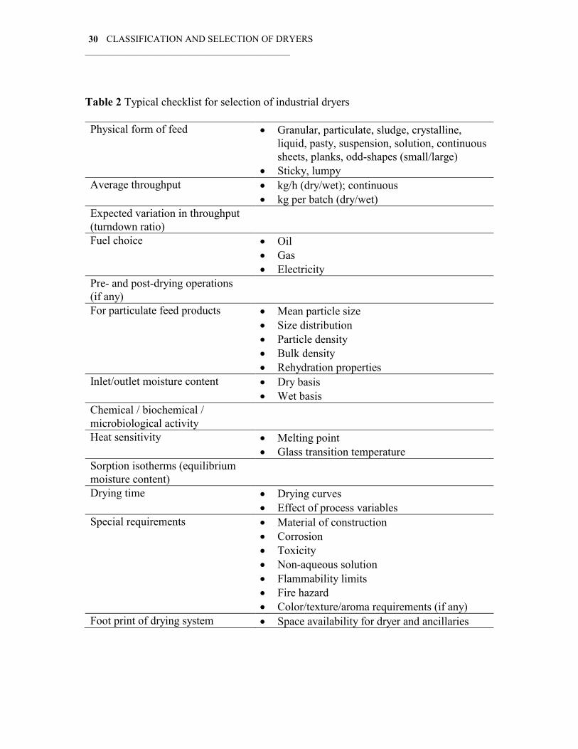
Table 2 presents a typical checklist most dryer vendors use to select and quote an industrial dryer.
CLASSIFICATION AND SELECTION OF DRYERS
___________________________________________ 30
Table 2 Typical checklist for selection of industrial dryers Physical form of feed Granular, particulate, sludge, crystalline,
liquid, pasty, suspension, solution, continuous sheets, planks, odd-shapes (small/large)
Sticky, lumpy Average throughput kg/h (dry/wet); continuous
kg per batch (dry/wet) Expected variation in throughput (turndown ratio)
Fuel choice Oil Gas Electricity
Pre- and post-drying operations (if any)
For particulate feed products Mean particle size Size distribution Particle density Bulk density Rehydration properties
Inlet/outlet moisture content Dry basis Wet basis
Chemical / biochemical / microbiological activity
Heat sensitivity Melting point Glass transition temperature
Sorption isotherms (equilibrium moisture content)
Drying time Drying curves Effect of process variables
Special requirements Material of construction Corrosion Toxicity Non-aqueous solution Flammability limits Fire hazard Color/texture/aroma requirements (if any)
Foot print of drying system Space availability for dryer and ancillaries

CLASSIFICATION AND SELECTION OF DRYERS
___________________________________________ 31
Drying kinetics play a significant role in the selection of dryers. Aside from simply deciding the residence time required, it limits the types of suitable dryers. Location of the moisture (whether near surface or distributed in the material), nature of moisture (free or strongly bound to solid), mechanisms of moisture transfer (rate limiting step), physical size of product, conditions of drying medium (e.g., temperature, humidity, flow rate of hot air for a convective dryer), pressure in dryer (low for heat-sensitive products), etc., have a bearing on the type of suitable dryer as well as the operating conditions. Most often, not more than one dryer type will likely meet the specified selection criteria. We will not focus on novel or special drying techniques here for lack of space. However, it is worth mentioning that many of the new techniques use superheated steam as the drying medium or are simply intelligent combinations of traditional drying techniques, e.g., combination of heat transfer modes, multi-staging of different dryer types. Superheated steam as the convective drying medium offers several advantages, e.g., higher drying rates under certain conditions, better quality for certain products, lower net energy consumption if the excess steam produced in the dryer is used elsewhere in the process, elimination of fire and explosion hazard. Vacuum steam drying of timber, for example, can reduce drying times by a factor of up to four while enhancing wood quality and reducing net fuel and electricity consumption by up to 70 percent. The overall economics are also highly favorable. 4. SELECTION OF A DRYER BASED ON QUALITY
As the product quality requirements become increasingly stringent and as the environmental legislation becomes more and more demanding it is often found that we need to switch from one drying technology to the others. The rising cost of energy as well as the differences in the cost of fossil fuels versus electrical energy can also affect the choice of a dryer. Since up to 70 percent of the life cycle cost of a convective dryer is due to energy it is important to choose an energy-efficient dryer where possible even at a higher initial cost. Note that energy costs will continue to rise in the future so this will become increasingly important. Fortunately, improved efficiency also translates into better environmental implications in terms of reduced emissions of the greenhouse gas (CO2) as well as NOx resulting from combustion.
Following is an example of how selection of the dryer is affected by quality of the dried product that may be used as raw material to produce different consumer products. Shah and Arora (1996) have surveyed the various possible dryers used for crystallization/drying of polyester chips from an initial moisture content of about 0.3-0.5% (w.b.) to under 50 ppm. Aside from low average moisture content it is also necessary to ensure uniform distribution of moisture, especially for some certain products, e.g., production of thin films. The uniformity constraint is less severe if the chips are to be used to make PET bottles. Figure 1 shows schematics of the crystallization/drying steps involved. Generally, it is a two-step process. The material is heat-sensitive. The initial crystallization/drying is faster than the drying step at low moisture levels. A two-stage dryer is indicated and is commonly used. It is possible to

CLASSIFICATION AND SELECTION OF DRYERS
___________________________________________ 32
use different dryer types for each stage as shown in Figure 2. A single dryer type (e.g., column or packed bed dryer with the chips moving downward slowly under gravity) is cheaper and hence recommended for the lower quality grade but a more expensive fluid bed followed by another fluid bed or column dryer may be needed for the higher quality grade. Note that numerous alternatives are possible in each case. It is also important to operate the dryers at the correct conditions of gas flow rate, temperature and humidity. Dehumidified air is needed to achieve low final moisture contents in accordance with the equilibrium moisture isotherms of the product.
Column dryer with internal tube
Multi-stage fluid bed
Wet chips 500-1000 ppm
moisture
< 50 ppm
moisture
Crystallizer/dryer
Final Dryer
Continuous
DIRECT
Continuous
DIRECT
Batch
INDIRECT
Batch
INDIRECT
Vacuum tumbler
Fluid bed
Vibro-fluid bed
Pulsed fluid bed
Vortex (spouted) bed
Column dryer (with mixer)
Paddle dryer
Vacuum tumbler
Paddle dryer
Figure 1 Schematic diagram of crystallization/drying steps in the production of polyester chips

CLASSIFICATION AND SELECTION OF DRYERS
___________________________________________ 33
e.g. for magnetic tape e.g. for speciality fibre,
film
e.g. for PET bottles,
staple fibre, etc.
Polymers Chips:
Quality Parameter
HIGH MEDIUM AVERAGE
A. Crystallizer: fluid bed
B. Finish dryer:
Multi-stage fluid bed
with dehumidified air
A. Crystallizer: fluid bed
or pulse fluid bed or
paddle crystallizer
B. Finish dryer:
Column dryer with a
central tube for
smooth downward
flow of chips
Single column
crystallizer/dryer with
a mixer in the top
crystallizer section
to avoid agglomeration
Low capital/operating
cost, smaller space
requirements
Figure 2 Possible dryer types for drying of polyester chips
Another example of dryer selection is related to the choice of a suitable atomizer
for a spray dryer. A spray dryer is indicated when a pumpable slurry, solution or suspension is to be reduced to a free-flowing powder. With proper choice of atomizer, spray chamber design, gas temperature and flow rate it is possible to “engineer” powders of desired particle size and size distribution. Table 3 shows how the choice of the atomizer affects chamber design, size, as well as energy consumption for atomization and particle size distribution. The newly developed two-fluid sonic nozzles appear to be especially attractive choices when nearly monodisperse powders need to be produced from relatively moderate viscosity feeds (e.g., under 250 cp) at capacities up to 80 t/h by using multiple nozzles. More examples may be found in Masters (1985).
Table 3 Spray drying of emulsion-PVC. Effect of selection of atomizer on spray dryer performance: A Comparison between different atomizers Parameter Rotary disk Two-fluid
(sonic) Two-fluid (standard)
Dryer geometry Conical/cylindrical H/D 1.2-1.5
Tall-form Cylindrical H/D 4
Tall-form Cylindrical H/D 5
Evaporation capacity (water)
1600 kg/h 1600 kg/h 1600 kg/h
Chamber (D H) 6.5 m 8 m 3.5 m 15 m 3 m 18 m Number of nozzles 1, 175-mm disk
15,000 rpm 16 nozzles 4 bar pressure
18 nozzles 4 bar pressure
Power for atomizer 25 W/kg slurry 20 W/kg slurry 80 W/kg slurry

CLASSIFICATION AND SELECTION OF DRYERS
___________________________________________ 34
Capital cost High Medium Medium Operating cost Medium Low High
New dryers are being developed continuously as a result of industrial demands. Over 250 US patents are granted each year related to dryers (equipment) and drying (process); in the European Community about 80 patents are issued annually on dryers. Kudra and Mujumdar (2000) have discussed a wide assortment of novel drying technologies, which are beyond the scope of this chapter. Suffice it to note that many of the new technologies (e.g., superheated steam, pulse combustion – newer gas-particle contactors as dryers) will eventually replace conventional dryers in the next decade or two. New technologies are inherently more risky and more difficult-to-scale-up. Hence there is natural reluctance to their adoption. Readers are encouraged to review the new developments in order to be sure their selection is the most appropriate one for the application at hand.
Some conventional and more recent drying techniques are listed in the Table 4. Table 4 Conventional versus innovative drying techniques Feed type Dryer type New techniques* Liquid Suspension Drum
Spray Fluid/spouted beds of inert
particles Spray/fluid bed combination Vacuum belt dryer Pulse combustion dryers
Paste/sludge Spray Drum Paddle
Spouted bed of inerts Fluid bed (with solid backmixing) Superheated steam dryers
Particles Rotary Flash Fluidized bed (hot air
or combustion gas)
Superheated steam FBD Vibrated bed Ring dryer Pulsated fluid bed Jet-zone dryer Yamato rotary dryer
Continuous sheets (coated paper, paper, textiles)
Multi-cylinder contact dryers
Impingement (air)
Combined impingement/radiation dryers
Combined impingement and through dryers (textiles, low basis weight paper)
Impingement and MW or RF *New dryers do not necessarily offer better techno-economic performance for all products

CLASSIFICATION AND SELECTION OF DRYERS
___________________________________________ 35
CLOSING REMARKS It is difficult to generate rules for both classification and selection of dryers because exceptions occur rather frequently. Often, minor changes in feed or product characteristics result in different dryer types being the appropriate choices. It is not uncommon to find different dryer types being used to dry apparently the same material. The choice is dependent on production throughput, flexibility requirements, cost of fuel as well as on the subjective judgment of the individual who specified the equipment.
We have not considered novel dryers in this chapter. Kudra and Mujumdar (2000) have discussed in detail most of the non-conventional and novel drying technologies reported in the literature. Most of them have yet to mature; a few have been commercialized successfully for certain products. It is useful to be aware of such advances so that the user can make intelligent decisions about dryer selection. Since dryer life is typically 25-40 years that effect of a poor “prescription” can have a long-term impact on the economic health of the plant. It is typically not a desirable option to depend exclusively on prior experience, reports in the literature or vendors’ recommendations. Each drying problem deserves its own independent evaluation and solution. REFERENCES Baker, C.G.J., 1997, Dryer Selection, pp. 242-271, in C.G.J. Baker (Ed.) Industrial Drying of Foods, Blackie Academic & Professional, London. Kudra, T., Mujumdar, A.S., 2000, Advanced Drying Technologies, Marcel Dekker, New York. Kudra, T., Mujumdar, A.S., 1995, Special Drying Techniques and Novel Dryers, pp. 1087-1149, in A.S. Mujumdar (Ed.) Handbook of Industrial Drying, 2nd Edition, Marcel Dekker, New York. Masters, K., 1985, Spray Drying Handbook, Halsted Press, New York. Mujumdar, A.S. (Ed.), 1995, Handbook of Industrial Drying, 2nd Edition, Marcel Dekker, New York. Schiffmann, R.F., 1995, Microwave and Dielectric Drying, pp. 345-372, in A.S. Mujumdar (Ed.) Handbook of Industrial Drying, 2nd Edition, Marcel Dekker, New York. Shah, R.M., Arora, P.K., 1996, Two Fluid Nozzles and their Application in Spray Drying of E-PVC, pp. 1361-1366, in C. Strumillo, Z. Pakowski, A.S. Mujumdar (Eds.) Drying’96: Proceedings of the Tenth International Drying Symposium, Lodz, Poland.

CLASSIFICATION AND SELECTION OF DRYERS
___________________________________________ 36
Slangen, H.J.M., The Need for Fundamental Research on Drying as Perceived by the European Chemical Industry, to appear in Drying Technology – An International Journal, 18(6), 2000. van't Land, C.M., 1991, Industrial Drying Equipment: Selection and Application, Marcel Dekker, New York.

Professor A. S. MujumdarME Department, NUS
E-mail - [email protected]
ME5202 INDUSTRIAL TRANSPORT PROCESSES
Fluidized Bed drying-An Overview
Contents
• Introduction to fluidized beds - Fundamentals
• Heat transfer in FBs
• Mass transfer in FBs
• An example calculation
• Application to drying
• Modeling a fluid bed dryer
• Key references (given at the end)

Fluid Beds - Basics
Fluidized beds: Particle
suspended in an upward gas
stream
Pressure drop in fixed beds
Pressure drop through packed bed / fixed bed of uniform
sized solids is correlated by Ergun equation
It has two factors, viscous force and the kinetic energy force
At low Reynolds number only viscous losses predominate
At high Reynolds number only kinetic energy losses need to be considered
Pressure drop & Minimum Fluidization Velocity
At the onset of fluidization, the gravity force on the particles in the bed must be
balanced by the drag, buoyancy, and pressure forces.

Pressure drop & Minimum Fluidization Velocity
The umf, the superficial velocity at minimum fluidizing condition is found by using
expression for !p/L
In a simplified form
For small particles (ReP < 20)
Or
Pressure drop & Minimum Fluidization Velocity
or
Wen and Yu have found for variety of systems
and
for small particles the simplified form is
for larger particles the simplified form is
For larger particles (ReP > 20)
For whole range of Reynolds number

Geldart’s Classification
A: Aeratable (Umb > Umf) Material has significant deaeration time (FCC Catalyst)
B: Bubbles Above (Umb = Umf) 500 micron sand
C: Cohesive (Flour, Fly Ash)
D: Spoutable (wheat, 2000 micron polyethylene pellets)
Group Characteristics and Properties
A
• Good fluidization quality, aeratable, easily fluidized, smooth at low
velocity and bubbling at higher velocity and slug at high velocity, bed
expands, Good solids mixing
• Small mean particle size, low density, typically 30< dp !"##$%&'()&
*!"+##&,-%-3.
B
• Good fluidization quality, sand-like particles, vigorous bubbling, slug
at high velocity, small bed expansion, good solids mixing in bubbling
• ./012'33/&+#$%!dp!4##$%5&"+##,-%-3!*!+###,-%-3
C
• Bad fluidization quality, cohesive due to strong interparticle force,
severe slugging and agglomeration, may generates electrostatic
charges, poor solids mixing.
• Fine and ultra-fine particles
D
• Poor fluidization quality, spoutable, difficult to fluidize in deep bed
depth, large bubbles, severe channeling, relatively poor solids mixing
• Large and/or dense particles, typically dp 64##$%5&*6"+##,-%-3
Geldart’s Classification contd…

Geldart’s Classification contd…
Geldart’s Classification contd…

Fluidization Regimes
Velocity Increasing
Fluidization Regimes: Description
Velocity range Regime Fluidization Features and Appearance
0 " U " Umf Fixed Bed Particles are quiescent; gas flows through interstices
Umf " U " Umb Particulate
Regime
Bed expands smoothly and homogeneously with small-scale particle
motion; bed surface is well defined
Umb " U " Ums Bubbling Regime Gas bubbles form above distributor, coalesce and grow; gas bubbles
promote solids mixing during rise to surface and breakthrough
Ums " U " UC Slug flow Regime Bubble size approaches bed cross section; bed surface rises and falls
with regular frequency with corresponding pressure fluctuation
UC " U " Uk Transition to
turbulent
Fluidization
Pressure fluctuation decrease gradually until turbulent fluidization
regime is reached
Uk " U " Utr Turbulent Regime Small gas voids and particle clusters and streamers dart to and fro;
bed surface is diffused and difficult to distinguish
U # Utr Fast Fluidization Particles are transported out of the bed and need to be replaced and
recycled; normally has a dense phase region at bottom coexisting
with a dilute phase region on top; no bed surface
U » Utr Pneumatic
Conveying
Usually a once-through operation; all particles fed are transported
out in dilute phase with concentration varying along the column
height; no bed surface

Fluidization Regimes: Description
Transition between regimes
Smooth or particulate fluidization
Bubbling or aggregative fluidization
Slugging criteria
Equations have been published for transition lines
between various regimes. This map can be used to
identify the type of flow regime that will exist for a
given particle under specific flow conditions.
Design of distributor in fluidized beds
! Uniform gas sparging is govern by the effective design of gas distribution
system and is very important to have uniform heat transfer
! Parameter affecting performance of Gas distribution system comprise of;
! A good distributor should;
" Gas Sparger geometry
" Gas chamber geometry
" Pressure drop across the gas distribution system
" Obtain a spatially uniform gas distribution, without stagnant zones
" Prevent solids loss by leakage
" Minimize solid erosion
" Avoid choking of the distributor
" Have a definite and non-changing (with time) pressure drop for the gas

Design of distributor in fluidized beds
The pressure drop across the distributor 78) is used as the criterion for
design, and 78)5 values varying from 0.01 to 1.0 times the pressure drop
across the bed 789 have been suggested.
Siegel (1986):
!Pd/!Pb = 0.14 - 0.22 [Galileo number (1 - 10,000)]
Kunii & Levenspiel (1991):
!Pd/!Pb = 0.1 – 0.3
Pressure Drop across the Distributor
" Siegel, M. H., Merchuk, J.C., Schugerl, K., 1986. Air-Lift Reactor Analysis: Interrelationships between Riser,
Downcomer and Gas-Liquid Separator Behavior, including Gas Recirculation Effects. AIChE Journal 32(10),
1585-1595
" Kunni, D., Levenspiel, O., 1991. Fluidization Engineering, 2nd Ed., Butterworth-Heinemann, Boston.
Side entry:
Nozzle Position (Litz, 1972)
noz0.5D0.2DH $% 100DD
noz&, when
noz18DH % 100DD
noz', when
Bottom entry:
( )nozDD3H *% 36DD
noz&, when
noz100DH % 36DD
noz', when
Where, D - diameter of gas distribution chamber
Dnoz - diameter of the nozzle
H - distance between the nozzle centerline and the
distributor plate
" Litz, W. J., 1972. Design of gas distributors. Chemical Engineering 13, 162-166.
Design of distributor in fluidized beds

Different types of fluid beds / modifications
A packed bed is composed of cubes 0.02 m on a side. The bulk density
of the packed bed, with air, is 980 kg/m3. The density of the solid cubes is
1500 kg/m3.
: Calculate the void fraction (+) of the bed.
: Calculate the effective diameter (Dp) where Dp is the diameter of a sphere
having the equivalent volume.
: Determine the sphericity of the cubes.
: Estimate the minimum fluidization velocity using water at 38 C and a tower
diameter of 0.15 m.
Example
fluidfluidsolidssolids
solidssolidsfluidfluidbedbed
solidsfluidbedsolidsfluidbed
VV
VVV
WWWandVVVknowWe
FractionVoid
,,
,,,
&&
$%
$%$%:

Example contd…..
35.0
1500
980
11
3
3
%*%*%
*%-.
m
kgm
kg
V
VV
andVV
solids
bed
bed
solids
bedbedbed
solidssolidsbedbed
,,
+
,,
+,,
( ) mDD
Da
diameterEffective
pp
p
025.06
02.0
6
33
33
%.%
%
/
/( )
81.066
6
63131
%01
234
5%%6//
a
a
Sphericity
s
( ) ( )
222
3
2
495980.93
9943
1500
75.11150
sm
kg
s
m
m
kg
m
kg
uDD
ug
VelocityonFluidizatiMimimum
fmfps
mf
mfps
mff
fp
%701
234
5 *
889
:
;;<
=$
6
*
6%*
,
>+
+
,,,
Example contd…..
( )2
22
5
3
2
3
3
2
3
10748.9445.0025.081.0
99475.175.1
445.014
1
mf
mf
mfps
mff
mfmfs
usm
kgu
m
kg
D
u7?%
77
77%
6
7
%.%6
+
,
++
( ) ( ) ( )
( ) ( ) ( )
s
mu
sm
kgu
sm
kgu
sm
kg
usm
kg
m
usm
kgcp
D
u
mf
mfmf
mf
mf
mfps
mfmf
071.0
4959159710748.90
1597
445.0025.081.0
001.0693.0445.011501150
2222
2
22
5
22
322322
%
*7$7?%
7%
77
7001
2334
577*7
%6
7*7
+
>+

Heat Transfer in fixed and Fluidized beds
• Main advantage of fluidized beds is the extremely large area of solid surface
exposed to the fluidizing media
• High solid surface area greatly facilitates solid-to-gas heat transfer
• Because of the solids mixing generated within the bulk of a bubbling gas
fluidized bed, temperature gradients are reduced to negligible proportions
• High rates of heat transfer are obtainable between the fluidizing solids and
the immersed transfer surface
Particle-to-gas heat transfer
Bed-to-surface heat transfer
Use of immersed surfaces

Heat Transfer in Fixed Beds
Heat transfer in fixed bed consists of following mechanisms
(1) conduction heat transfer between particles,
(2) convective heat transfer between particles and fluid,
(3) interaction of both (1) and (2),
;+<&=')1'>1?@&A@'>&>B'(CD@B&9@>E@@(&0'B>123@C&'()&>A@&D3FE1(-&-'C
(5) Heat transfer between bed wall and bed particles
(1) Particle to fluid heat transfer
Heat transfer to single particle can be expressed as
Heat transfer coefficient can be evaluated as
(2) Heat transfer through wall (one dimensional model)
For homogeneous model, temperature of fluid and of bed are assumed identical
andfor
(3) Heat transfer through wall (two dimensional model)
For homogeneous model,
temperature of fluid and of bed are assumed identical
Heat Transfer in Fixed Beds
andfor
(4) Effective radial thermal conductivity
andfor

Heat Transfer in Fluid beds
• Gas to particle heat transfer coefficients are typically small, of the order of 5 - 20 W/m2K
• However, because of the very large heat transfer surface area provided by a mass of small
particles, the heat transfer between gas and particles is rarely limiting in fluid bed heat
transfer
• One of the most commonly used correlations for gas-particle heat transfer coefficient is that
of Kunii and Levenspiel (only for low particle Reynolds numbers)
• Gas to particle heat transfer is relevant where a hot fluidized bed is fluidized by cold gas
• While following are the correlation suggested based on experimental data*
Heat transfer in a bubbling fluidized bed
for
for
for
*Chen, J.C., Heat Transfer in handbook of fluidization and fluid systems, 2003
Analysis of Gas-particle heat transfer
The energy balance across the element gives
Integrating with boundary conditions Tg = Tg0 at L = 0

Analysis of Gas-particle heat transfer
The distance Ln, in which the gas-to-particle temperature falls by a factor
Is given by,
The distance over which the temperature distance is reduced to half its initial value,
L0.5 is then
Analysis of Gas-particle heat transfer
A bed of +4#>m particles is operating at 150GH. The temperature and superficial velocity
of the incoming gas are 550GH and 0.+ m/s, respectively. Approximately how far will
the incoming gas have penetrated into the bed before it is cooled to 350GH
Gas physical properties can be estimated at average temperature over the specified
B'(-@I&J(&>A1C&0'B>12K3'B&2'C@&>A@&'?@B'-@&>@%0@B'>KB@&1C&+4# GHI&L@(2@&>A@&0A/C12'3&
properties of air
M'C&?@3F21>/&'>&+4#GH&DFB&'(&1(3@>&?@3F21>/&FD&#I+%NC&'>&44#GH&E133&9@&#IO4%NC

Heat Transfer in Fluid beds
Bed to surface heat transfer
In a bubbling fluidized bed the coefficient of heat transfer between bed and immersed
surfaces (vertical bed walls or tubes) can be considered to be made up of three additive
components
The particle convective component hcp, which is dependent upon heat transfer
through particle exchange between the bulk of the bed and the region adjacent to
the transfer surface (heat transfer due to the motion of packets of solids carrying heat
to and from the surface)
The interphase gas convective component hgc, by which heat transfer between
particle and surface is augmented by interphase gas convective heat transfer
The radiant component of heat transfer hr
Thus,
Approximate range
of significance
+#>m 1mm > 800 >m and at
higher static
pressure
Higher temperatures
(> 900 K) and
difference
Heat Transfer in Fluid beds
Particle convective heat transfer
On a volumetric basis the solids in the fluidized bed have about one thousand times the
heat capacity of the gas and so, since the solids are continuously circulating within the
bed, they transport the heat around the bed. For heat transfer between the bed and a
surface the limiting factor is the gas conductivity, since all the heat must be transferred
through a gas film between the particles and the surface
Heat transfer from bed particles to an immersed surface

Heat Transfer in Fluid beds
The particle-to-surface contact area is too small to allow significant heat transfer.
Factors affecting the gas film thickness or the gas conductivity will therefore influence
the heat transfer under particle convective conditions.
Decreasing particle size, for example, decreases the mean gas film thickness and so
improves hpc. However, reducing particle size into the Group C range will reduce
particle mobility and so reduce particle convective heat transfer. Increasing gas
temperature increases gas conductivity and so improves hpc.
Particle convective heat transfer is dominant in Group A and B powders. Increasing
gas velocity beyond minimum fluidization improves particle circulation and so
increases particle convective heat transfer.
The heat transfer coefficient increases with fluidizing velocity up to a broad maximum
hmax and then declines as the heat transfer surface becomes blanketed by bubbles.
Particle convective heat transfer
Heat Transfer in Fluid beds
Bed to surface heat transfer
Range of fluidized bed-to-surface heat transfer coefficients

Heat Transfer in Fluid beds
Bed to surface heat transfer
Effect of fluidizing gas velocity on bed – surface heat transfer coefficient
Heat Transfer in Fluid beds
Particle convective heat transfer
The maximum in hpc occurs relatively closer to Umf for Group B and D powders
since these powders give rise to bubbles at Umf and the size of these bubbles
increase with increasing gas velocity
Group A powders exhibit a non-bubbling fluidization between Umf and Umb and
achieve a maximum stable bubble size.
Zabrodsky (1966) has given correlation for hmax for group B particles
Khan (1978) has given correlation for hmax for group A particles

Heat Transfer in Fluid beds
Gas convective heat transfer
Gas convective heat transfer is not important in Group A and B powders where the flow of
interstitial gas is laminar but becomes significant in Group D powders, which fluidize at
higher velocities and give rise to transitional or turbulent flow of interstitial gas
In gas convective heat transfer the gas specific heat capacity is important as the gas
transports the heat around.
Gas specific heat capacity increases with increasing pressure and in conditions where gas
convective heat transfer is dominant, increasing operating pressure gives rise to an improved
heat transfer coefficient hgc.
Baskakov and Suprun (1972) has given correlation for hgc
where Um is the superficial velocity corresponding to the maximum overall bed heat transfer
coefficient
Heat Transfer in Fluid beds
Gas convective heat transfer to immersed surfaces
Several approaches have been used to estimate hc
The most common approach assigns thermal resistance to a gaseous boundary layer at the
heat transfer surface, the enhancement of heat transfer is then attributed to the scouring
action of the solid particles on the gas film, decreasing the effective film thickness
Lava’s correlation (1952) for vertical surfaces, for larger particles, is
Wender and Cooper’s correlation (1958) for vertical tubes,
for
Where
Where r is the radial position of the heat transfer tube and Rb is the radius of the bed

Gas convective heat transfer to immersed surfaces
Heat Transfer in Fluid beds
Vreedenberg’s correlation (1958) for horizontal tubes,
for
and
for
Where
Changed
Equation
Heat Transfer in Fluid beds
Radiative heat transfer
For temperatures beyond 600oC radiative heat transfer plays an increasing role
and must be accounted for in calculations
For rule of thumb estimate, the radiative heat transfer component can be
estimated using absolute temperatures and an adaptation of the stefen -
Boltzman equation in the form
where +r is the reduced emissivity to take into account the different emissivity properties of
surface +s and bed +b and is given by
An alternative correlation given by Panov et al. (1978) for approximate estimate is

Mass transfer
• Main applications of fluidized beds – Fluidized catalytic cracking; Combustion and
Gasification; Drying; Granulation;
• The performance of fluidized beds in all the above processes is affected by the
interface mass transfer
• Many times the mass transfer in fluidized beds is a potential rate controlling step in
fluidized bed reactors
• Depending on the type gas-solid interactions, the rate controlling mechanism can be
1. Particle – gas mass transfer (Gas film diffusion) control
2. Pore diffusion control
3. Surface phenomenon control

Mass transfer in fluidized beds
There are two approaches that can be used for prediction of mass
transfer rates in fluidized beds
• Homogeneous bed approach – considers fluidized bed behaving
as a fixed bed reactor and correlate the mass transfer coefficient
in fluidized bed in similar manner to that in a fixed bed based on
plug-flow model
• Bubbling bed approach – Considers fluidized bed to consist of
two phases, a bubble and an emulsion phase, the gas interchange
between the two phases constitutes the rate of mass transfer
Sherwood Number – ratio of convective to diffusive mass transport
Schmidt Number – ratio of momentum to mass diffusivity
Reynolds Number – Comparison of Inertial force to viscous force
Reynolds Number – Comparison of gravitational and viscous force
Useful Dimensionless Numbers
Sc = Momentum diffusivity
Mass Diffusivity
Sh = Convective mass transfer coefficient
Diffusive mass transfer coefficient
Sc = !
"#
Sh = k L
#

Homogeneous Bed Approach
Transfer between single sphere and surrounding gas
Transfer rate of
A from particle
to gas
Concentration of
A at particle-gas
interphase
Concentration of
A in the bulk gas
stream
Mass transfer
coefficient of
single particle
• Rate of mass transfer between well-dispersed sphere and surrounding air can be
written as
• The single particle mass transfer coefficient can be obtained from well established
correlation (Froessling, 1938)
• Eq (2)
where particle Reynolds number and Schmidt number can be defined as
The mass transfer coefficient is proportional to diffusion coefficient of gas and inversly
proportional to diameter of particle
Homogeneous Bed Approach
Transfer between single sphere and surrounding gas
For non-spherical particle the sieve diameter (dp) will replace the diameter of
the particle and the equation becomes
where particle Reynolds number is

Homogeneous Bed Approach
Transfer between fixed bed particles and flowing gas
Rate of mass transfer between fixed bed of particles and surrounding gas can be written
in the same fashion as the one for single particle
Combined mass
transfer rate
from all the
particles
Concentration of
A at particle-gas
interphase
Concentration of
A in the bulk gas
stream
Average mass
transfer
coefficient of
particles
Total exterior
surface of all
individual
particles
Homogeneous Bed Approach
Transfer between fixed bed particles and flowing gas
The correlation for the average mass transfer coefficient kg,bed was given by Ranz (1952)
Total particle exterior surfaces Sex,particles
Method of Kunni Levenspiel
Volume of bes
segmentBed voidage
Particle surface to
particle volume ratio
Sphericity of bed
particles
Hence the equation for total exterior particle
surfaces becomes

Homogeneous Bed Approach
Transfer between fluidized bed particles and fluidizing gas
Average mass
transfer coefficient
associated with
fluidizing particles
Total exterior
surfaces of the
fluidized particles in
the segment of bed
The rate of particle to gas mass transfer in the differential segment of fluidized bed can
be written as
Kg,bed for fluidized beds is always higher than that for fixed beds
Homogeneous Bed Approach
Average mass transfer coefficient for fluidizing particles
The mass transfer coefficient for fluidized bed particles can be lower or higher than that
of single particles
Generally for low Reynolds numbers the mass transfer coefficient for single particles is
higher than for fluidizing particles however, reverse is true for higher particle
Reynolds numbers (>80)
Resnick and White ("P+P) reported the average mass transfer coefficient for the
fluidizing particles (for air system with Sc = 2.35)

Homogeneous Bed Approach
Average mass transfer coefficient for fluidizing particles
Homogeneous Bed Approach
particle-gas mass transfer coefficient for
fluidized bed particles
Comparison of mass transfer coefficient for
fluidized bed and fixed bed
Particle – gas mass transfer coefficient for fluidized bed particles
• It should be noted that the same correlations can be used for fluidized beds and fixed beds…
• “Sh” for same group of particles continues to increase with the particle Reynolds number even
during the transition from fixed bed to fluidized bed operations
Using Sh equation for
single particle Eq (2) Using Sh equation for
single particle Eq (2)

Homogeneous Bed Approach
Limitations of Homogeneous bed approach
The experimentally measured coefficient values for the bed particles under fixed bed or
fluidized bed conditions can be lower or higher than the theoretically estimated
values
For fine particles the mass transfer coefficients were found to be well below the
estimated values from correlations
The measured mass transfer coefficient by this approach should be treated as empirical
in nature
Summary of particle-gas mass
transfer coefficient
Using Sh equation
for single particle
Eq (2)
Bubbling Bed Approach
Takes in to account existence of a two phases: bubble phase and
emulsion phase
Bubble phase – considered as spherical bubbles surrounded by spherical clouds
There are three different models available based on this approach
Kunni and Levenspiel (bubble – emulsion transfer)
Partridge and Rowe (cloud – emulsion transfer)
Chavarie and Grace (Empirical correlation for bubble- emulsion transfer)
BubbleCloud

Model of Kunni and Levenspiel
Model for vaporization or sublimation of A from all particles in bed
Assumptions:
Fresh gas enters the bed only as bubbles
Equilibrium is established rapidly between CA at gas-particle interphase and
its surroundings
These assumptions lead to the following equation in terms of bubble-emulsion mass
transfer coefficient (KGB)as follows
In this approach both cloud and the emulsion phases are assumed perfectly mixed
Model of Kunni and Levenspiel
Relation between KGB and Kg,bed
The equation reported in last slide for mass transfer by Kunni and Levenspiel can be
derived using the mass transfer rate equation for homogeneous bed approach
With the assumption that fresh gas enters the
bed only as bubbles the above equation
becomes
Where CA,b is the concentration of A in
bubble phase
Model of Kunni and Levenspiel
Relation between KGB and Kg,bed
The solutions of the previous equations finaly results in the following relation between
KGB and kg,bed
The definition of Sherwoods Number becomes
KGB for Nonporous and Nonadsorbing Particles
The particles dispersed in bubble phase will not contribute to any additional mass
transfer and hence; hence transfer across the bubble-cloud boundary therefore is the
only source of mass transfer
Hence
Where Kbc is the bubble-cloud interchange coefficient derived by Davidson and Harrison
as
KGB for highly adsorbing particles
For single particle
So the KGB equation becomes
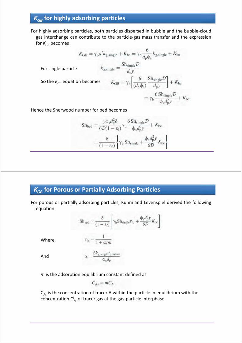
For highly adsorbing particles, both particles dispersed in bubble and the bubble-cloud
gas interchange can contribute to the particle-gas mass transfer and the expression
for KGB becomes
Hence the Sherwood number for bed becomes
KGB for highly adsorbing particles
For single particle
So the KGB equation becomes
For porous or partially adsorbing particles, Kunni and Levenspiel derived the following
equation
KGB for Porous or Partially Adsorbing Particles
Where,
And
m is the adsorption equilibrium constant defined as
CAs is the concentration of tracer A within the particle in equilibrium with the
concentration CiA of tracer gas at the gas-particle interphase.

The cloud surrounding the bubble is considered as the primary mass transfer boundary
and the bubble and the clod phases are considered as perfectly mixed single phase
as shown in the following figure
The mass transfer equation is
Model of Partidge and Rowe
Cloud
emulsion mass
transfer
coefficient
Cloud exterior
surface
Volume of gas
in the bubble-
cloud phase
Partidge and Rowe have given a correlation for mass transfer coefficient in terms of
Sherwood number as follows
where Sc is the Schmidt number as defined earlier while Rec is defined as
Model of Partidge and Rowe
Relative velocity
between rising
cloud and
emulsion
Diameter of
sphere with
the same
volume as the
cloud

Measurement of mass transfer rates for bubble containing ozone injected into an air-
fluidized two dimensional bed and proposed following empirical equation,
Table shows the models for kgc given by various researchers
Model of Chavarie and Grace
Table showing some more models for kgc given by various researchers
Model of Chavarie and Grace

The correlations for particle to gas mass and heat transfer coefficient are closely related
when the Sherwood number (Sh) is equivalent to Nusselt number (Nu) and the
Schmidt number (Sc) is equivalent to Prandtl number (Pr)
For example, the correlation for Nusselt number for particles in a fixed bed is expressed
as
The corresponding correlation equation for the Sherwood number has the form
Hence the correlations obtained for Nu (heat transfer) can be converted to Sherwood
number to obtain mass transfer coefficient, provided --- Sh @ Nu and Sc @ Pr
Relation between mass and heat transfer coefficient
Some Concluding Remarks on Mass Transfer in FB
Fluidized beds are very important for solid-fluid contact for various important
industrial applications
Heat as well as mass transfer is important for design considerations
When kinetic processes such as mass transfer are carried out with fluidized
beds the particles dispersed in bubble phase should be taken in to account
Mass transfer coefficient measured for the bed as a whole (kgbed) is model
dependent
For large particles (cloudless bubble bed) the plug flow model closely matches
the bed conditions in the bed and the mass transfer coefficient for bed should
be equal to single particle mass transfer coefficient
For fine particles kgbed << kgsingle

Application to drying
Fluidized bed drying
Fluidizing with hot air is an attractive means for drying many moist powders and
granular products
The technique has been used industrially for drying crushed minerals, sand,
polymers, fertilizers, pharmaceuticals, crystalline materials and many other
products.
The main reason for its popularity is
Efficient gas-solids contacting leads to compact units and relatively low capital cost
combined with high thermal efficiency
Very high heat and mass transfer and hence reduced drying times
The absense of moving parts, low maintenance cost and possibility of using
continuous mode
The main limitation is the material to be dried should be fluidizable and should
have narrow particle size distribution

Fluid Bed Dryer
Air suction
system:
Fan
Blower
compressorHeating system:
Electricity
Fuel
Steam
Dust separation
system:
Cyclone
Bag filter
Precipitator
Scrubber
Fluidized bed system:
Conventional
Modified
Hybrid / combined
Fluidized Bed Drying
Different designs of fluid bed dryers

Fluidized Bed Drying
• common FBD used in industry.
• bed temperature uniform, equal to the
product and exhaust gas temperatures.
• particle residence time distribution is
wide
• wide range of product moisture content.
• feed is continuously charged into FB of
relatively dry particles, this enhances
fluidization quality.
• a series of well-mixed continuous dryers
may be used with variable operating
parameters.
Well mixed fluid bed dryer
• vertical baffles are inserted to
create a narrow particle flow path.
• narrow particle residence time
distribution.
• nearly equal residence time for all
particles regardless of their size
• uniform product moisture content.
• length-to-width ratio from 5:1 to
30:1.
• inlet region may be agitated or
apply back-mixing, or use a flash
dryer to remove the surface
moisture.
Fluidized Bed Drying
Plug flow fluid bed dryer

Developments in Fluidized Bed Drying
: Conventional FBD’s use steady flow rate, constant temperature and operate in
batch or continuous mode at near atmospheric pressure with air as the
drying/fluidizing medium
: Modified FBDs may use pulsed flow, variable temperature, vibration to assist
fluidization, use superheated steam as drying medium, operate at reduced
pressure etc.
: FBDs may be used to dry slurries or continuous sheets (e.g. leather in a bed of
adsorbent particles)
: Fluidized beds compete with rotary dryers, conveyor dryers and moving bed
or packed bed dryers due to their advantages such as higher efficiency, better
heat/mass transfer rates, smaller floor area; ability to operate in batch or
continuous modes etc
: Limitations include high power consumption, attrition, need to have
fluidizable material etc
: Often a second stage after flash drying or spray drying where it is also used as
an agglomerate
FBD Classification
FB Dryers
Batch Continuous
HybridContinuous
input
Variable
input
MultistageSingle stage
Conventional ConventionalModified Modified
Batch (Well Mix) Plug Flow (narrow RTD) Well Mix (wide RTD)

FBD Classification
FB Dryers
Batch Continuous
Continuous input Variable input
Conventional Modified
Spout FBD
Pulsating FBDAgitated FBD Baffled FBD
Inert solid
FBD
FBD Classification
FB DryersBatch
Continuous
Single stage Multistage Hybrid
Conventional Modified
Immersed tubes
Vibrating FBD FB dryer cooler Spray FBD
Cyclone FBDWell mixed-Plug flow
Plug flow FBD
Well mix FBD

Modeling - Fluid Bed Dryer
Diffusion model
This model assumes that the drying of single particle in the fluidized bed is controlled
by the diffusion of moisture inside the particle
Empirical model
• In this approach the drying process is divided into different periods where drying
mechanisms in each drying period are different;
• The solution of Fick’s law of diffusion expresses the moisture content in terms of
drying time by exponential function;
• Experimental data obtained from fluid bed drying experiments can be correlated
using exponential function
Kinetic model
Single phase model - Explained later
Two-phase model - Explained later
Modeling - Fluid Bed Dryer
Single phase model
The fluidized bed is regarded essentially as a continuum
Heat and mass balances are applied over the fluidized bed
Assumption - particles in the bed are perfectly mixed
Mass balance
Energy balance
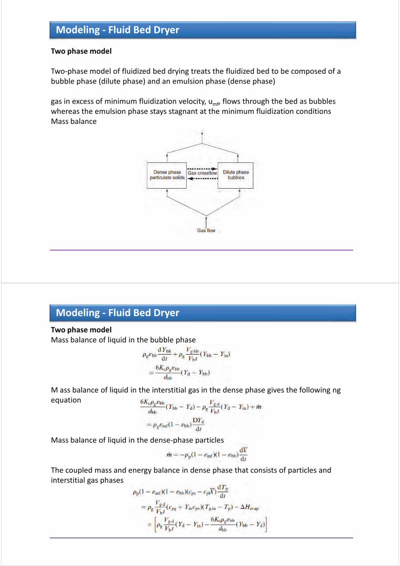
Modeling - Fluid Bed Dryer
Two phase model
Two-phase model of fluidized bed drying treats the fluidized bed to be composed of a
bubble phase (dilute phase) and an emulsion phase (dense phase)
gas in excess of minimum fluidization velocity, umf, flows through the bed as bubbles
whereas the emulsion phase stays stagnant at the minimum fluidization conditions
Mass balance
Modeling - Fluid Bed Dryer
Two phase model
Mass balance of liquid in the bubble phase
M ass balance of liquid in the interstitial gas in the dense phase gives the following ng
equation
Mass balance of liquid in the dense-phase particles
The coupled mass and energy balance in dense phase that consists of particles and
interstitial gas phases
Some questions for self study
For drying of certain product, the ambient air of 80% relative humidity is heated
to 70°C before entering the fluid bed dryer of uniform particle size.
• Discuss qualitatively, what will be the effect if the air is cooled down to 5°C
and reheated back to same temperature of 70°C before entering the dryer.
During which drying rate period will this be more useful
• Discuss what will be the effect on performance if the bed particles have wide
size distribution, Suggest improvements to tackle this situation.
• What will be the effect on drying if heated inert spherical particles of same
size are added in a bed of particles to be dried?
• How can one enhance the drying of a non-spherical particles in a fluidized
bed?
Key References
• Yang, W.C.; Handbook of Fluidization and Fluid –Particle Systems, Marcel Dekker, USA,
2003
• Kunni, D.; Levenspiel, O. Fluidization Engineering, 1969
• Mujumdar, A.S. Handbook of Industrial Drying, 3rd Ed; CRC Press: Boca Raton, FL,
2006

Visit us athttp://serve.me.nus.edu.sg/arun/ http://www.mujumdar.net78.net/

Professor A. S. Mujumdar
National University of Singapore
Drying Technology - An Overview
Supplementary Notes for students
ME5202 – Industrial Transport Processes
Contents
Introduction to Drying
Basic terms in drying
Why so many dryers (complex process)
Key criteria for classification
Criteria for dryer selection
Different dryer types
Energy related issues in drying
Special/Innovative techniques
Closure

Introduction to drying
Removal of a liquid from a solid/semi-solid/liquid to produce solid
product by thermal energy input causing phase change
(Sometimes converts solid moisture into vapor by sublimation eg.
Freeze drying with application of heat.)
Needed for the purposes of preservation and storage, reduction in
cost of transportation, etc.
Most common and diverse operation with over 100 types of dryers
in industrial use
Competes with distillation as the most energy-intensive
operation
Basics about drying
Drying particle
Energy Input by Moisture Output by
! Conduction
! Convection
! Radiation
! Microwave and Radio
Frequency Fields
! Combined mode
! Liquid diffusion
! Vapor diffusion
! Capillary flow (Permeability)
! Knudsen diffusion (Mean free
path < pore dia.)
! Surface diffusion
! Poiseuille flow
! Combination of above

Drying a Complex Process
Chemical/
biochemical
reactions
Phase change
Multicomponent
Moisture transportChange of physical
structure
Coupled with
mass
transfer
Input
Continuous/
intermittent
Change in
quality
Transient
Shrinkage
DRYING AS A
COMPLEX
THERMAL PROCESS
Drying based on heat input
I. Direct (Convective)
Direct
Dryer
Hot gas
Wet product Dry product
Humid gas
Drying medium directly contacts material to be dried and carries
evaporated moisture.
II. Indirect (Contact, Conduction)
Gas flow (low)
Wet product Dry product
Vacuum or low gas flow
Heat supplied
by heat exchanger
(through metal wall)

Drying based on heat input
III. Radiant
Wet feed Dry product
Vacuum or low gas flow to carry evaporated moisture away.
IV. Microwave or RF
Electromagnetic energy absorbed selectively by water (volumetric heating).
Heater (radiant)
Typically less than 50% of total heat supplied in most direct dryers
is used for evaporation. Water is the most common solvent removed
in dryers.
Summarization of Basic Terms
Terms/Symbol Meaning
Adiabatic saturation
temperature, Tad
Equilibrium gas temperature reached by unsaturated gas and vaporizing
liquid under adiabatic conditions. Only for air/water system, it is equal to
the wet bulb temperature
Bound moisture Liquid physically and/or chemically bound to solid matrix so as to exert a
vapor pressure lower than that of pure liquid at the same temperature
Constant rate drying period, NC Under constant drying conditions, drying period when evaporation rate
per unit drying area is constant (when surface moisture is removed
Dew point, Td Temperature at which a given unsaturated air-vapor mixture becomes
saturated
Dry bulb temperature, Tdb Temperature measured by a (dry) thermometer immersed in vapor-gas
mixture.
Equilibrium moisture content,
Xe
At a given temperature and pressure, the moisture content of moist solid in
equilibrium with the gas-vapor mixture (zero for non-hygroscopic
materials)
Critical moisture content, Xc Moisture content at which the drying rate first begins to drop (under
constant drying conditions)
Falling rate period
NF
Drying period under constant drying conditions during which the rate false
continuously with time
Free moisture, Moisture content in excess of the equilibrium moisture content (hence free
to be removed) at given air humidity and temperature.

Summarization of Basic Terms
Terms/Symbol Meaning
Humid heat Heat required to raise the temperature of unit mass of dry air and its
associated vapor through one degree (J kg-1 K-1)
Humidity, absolute, Y Mass of water vapor per unit mass of dry air (kg kg-1)
Humidity, relative Ratio of partial pressure of water vapor in gas-vapor mixture to
equilibrium vapor pressure at the same temperature.
Unbound moisture Moisture in solid which exerts vapor pressure equal to that of pure liquid
at the same temperature.
Water activity, awRatio of vapor pressure exerted by water in solid to that of pure water at
the same temperature
Wet bulb temperature, Twb Liquid temperature attained when large amount of air-vapor mixture is
contacted with the surface. In purely convective drying, drying surface
reaches Twb during constant rate period
Basic Terms
R.H. 50%
EMC
Bound moisture
Free moisture
Content
X Moisture Content(dry basis)X*
Unbound moisture
100%
T= Constant
Various types of moisture content

Basic Terms
Sorption Isotherm
Adsorption
Desorption
BC
AM
ois
ture
Co
nte
nt
20 40 60 80 100
% Relative Humidity
Basic Terms
0
100
X, kg water / kg dry solid
Relative
humidity
Non-hygroscopic
Nearly
non-
hygroscopic
Hygroscopic
porous
Colloidal
Colloidal, infinitely swelling
T = CONST.
Equilibrium moisture content curves for various types of solids
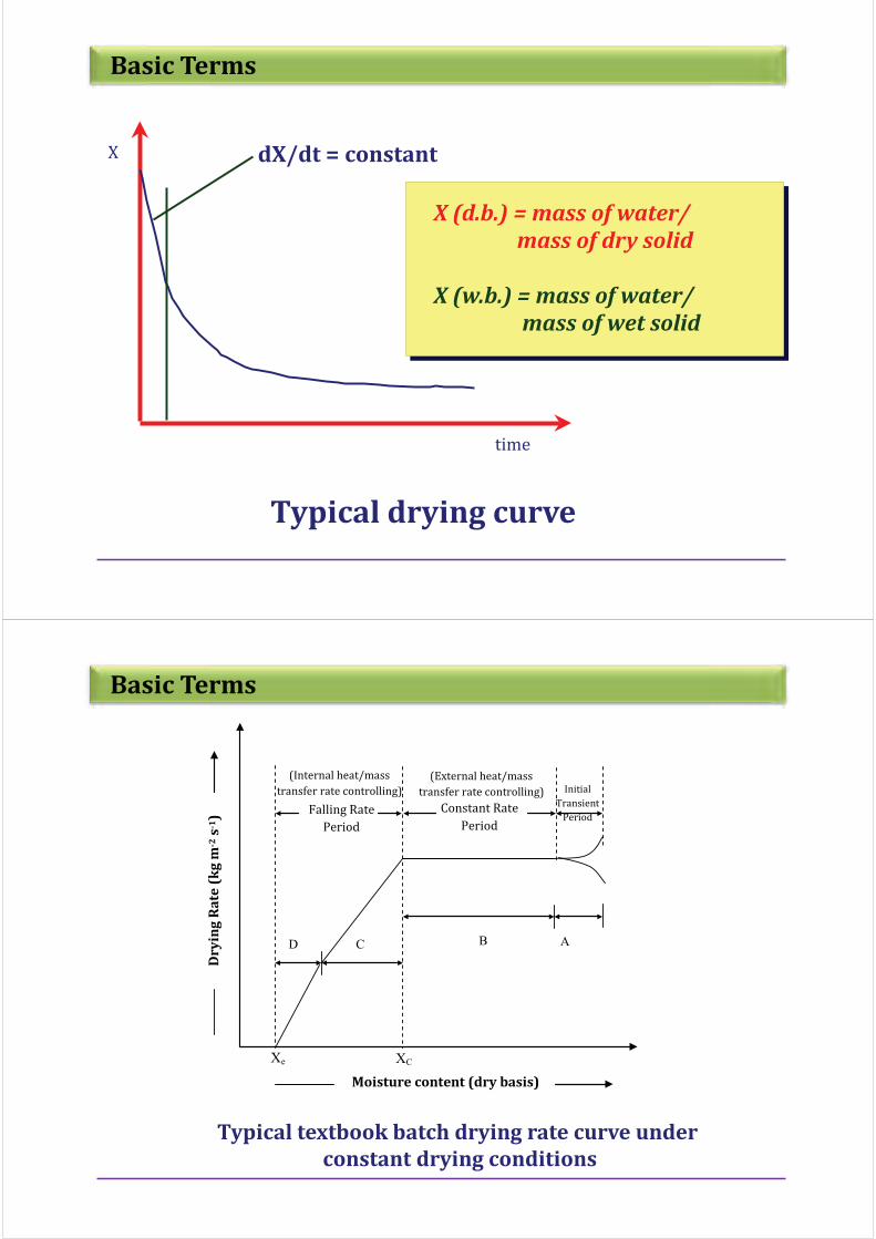
Basic Terms
Typical drying curve
X
time
dX/dt = constant
X (d.b.) = mass of water/
mass of dry solid
X (w.b.) = mass of water/
mass of wet solid
Basic Terms
Typical textbook batch drying rate curve under
constant drying conditions
Moisture content (dry basis)
Dry
ing
Ra
te (
kg
m-2
s-1
)
ABCD
Falling Rate
Period
Constant Rate
Period
Initial
Transient
Period
Xe XC
(Internal heat/mass
transfer rate controlling)
(External heat/mass
transfer rate controlling)

Basic Terms
NM
A
dX
dtor
M
A
dX
dt
s s f! " "
By convention, the drying rate, N, is defined as
an initial constant rate period where N = Nc = constant.
Nq
c
s
!#$
The constant rate period is governed fully by the rates of external heat and mass
transfer since a film of free water is always available at the evaporating surface
Nc can be calculated using empirical or analytical techniques to estimate the external
heat/mass transfer rates
The drying rate in the falling rate period(s) is a function of X (or Xf) and must be
determined experimentally for a given material being dried in a given type of dryer
Basic Terms
If the drying rate curve (N versus X) is known, the total
drying time required to reduce the solid moisture content
from X1 to X2 can be simply calculated by
tM
A
dX
Nd
s
X
X
! " %1
2
Model Drying time
Kinetic model, td = Drying time to reach final moisture content X2 from initial moisture content X1
N = N(X)
(General)
N = Nc
(Constant rate period)
N = aX + b
(Falling rate period)
N = Ax
tM
A
dX
Nd
s
X
X
! %2
1
tM
A
X X
Nc
s
c
! ""( )
2 1
tM
A
X X
N N
N
Nf
s!""
( )
( )ln
1 2
1 2
1
2
tM X
AN
X
Xf
s c
c
c! ln2
X X X c* & &
2
NM
A
dX
dt
s! "
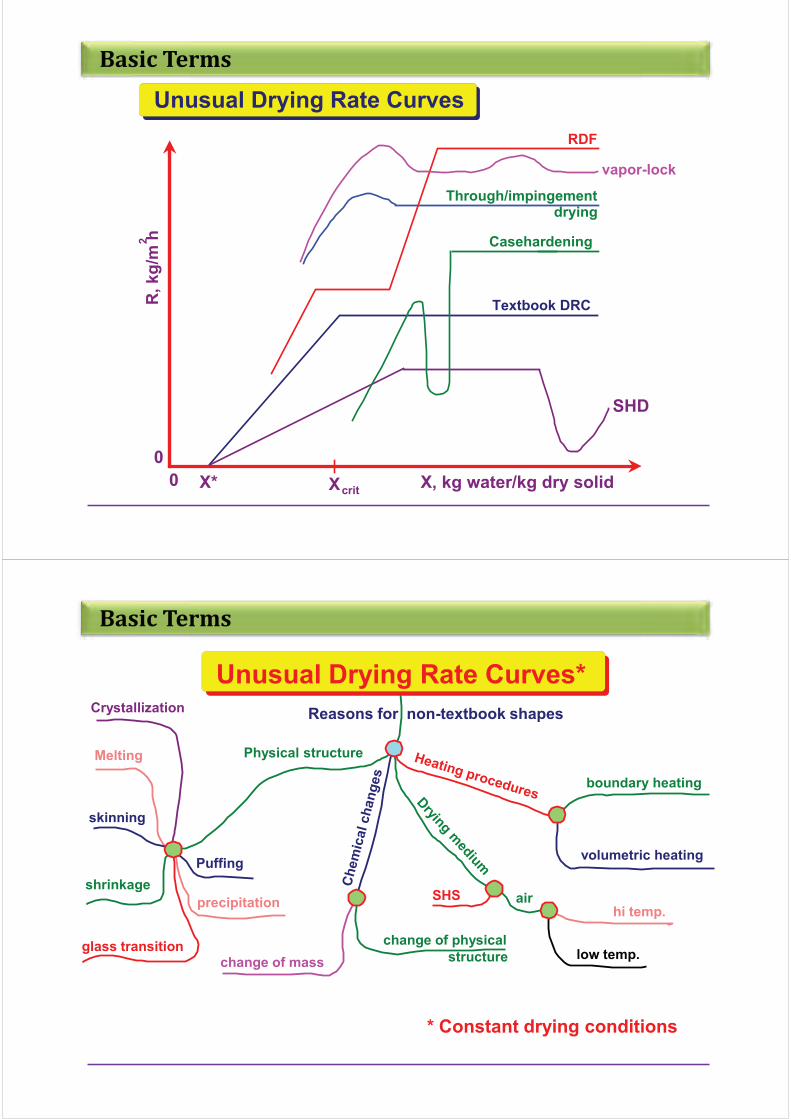
Basic Terms
R,
kg
/m h2
X, kg water/kg dry solid
0
0
Textbook DRC
X*
SHD
Xcrit
Casehardening
Through/impingement drying
RDF
vapor-lock
Unusual Drying Rate Curves
Basic Terms
Reasons for non-textbook shapes
Physical structure
Crystallization
Melting
skinning
glass transition
Puffing
shrinkage
precipitation
change of mass
change of physical
structure
boundary heating
volumetric heating
SHS airhi temp.
low temp.
Unusual Drying Rate Curves*
* Constant drying conditions

Basic Terms
Diffusion during drying of solids
'
'
'
'
X
tD
X
x
f
L
f!
2
2
Solution subject to the following initial and boundary conditions
Xf = Xi, everywhere in the slab at t = 0
Xf = 0, at x = a (top, evaporating surface), and
at x=0 (bottom, non-evaporating surface)
Fick’s law
'
'
X
x
f! 0
Liquid diffusion model
DL = constant, X2 = Xc
Slab; one-dimensional diffusion,
evaporating surface at X*
X = average free moisture content
a = half-thickness of slab
ta
D
X
Xf
L
!4 8
2
1
2
2( (
ln
Diffusion (Contd)
GeometryBoundary
conditions
Dimensionless average free
M.C.
Flat plate of
thickness 2b
Infinitely long
cylinder of radius R
Sphere of radius R
t b z b X X! " ) ) !00
; ;
t z b X X* ! + !0; ; *
X
nn
b
D t
b
L
n
!
"" "
,-.
/01
2
34
5
67
!
8
#
8
1
2 12 1
4
2
2
2
1
((
( )exp ( )
XR
D tn
L nn
! "!
8
#41
2 2
2
1 99exp( )
t r R X X! ) ) !0 00
; ;
t r R X X* ! !0; ; *
t r R X X! ) ) !0 00
; ;
t r R X X* ! !0; ;*
Xn
n
R
D t
R
L
n
!" ,
-./01
2
34
5
67
!
8
#6 1
2 2
2 2
1((
exp
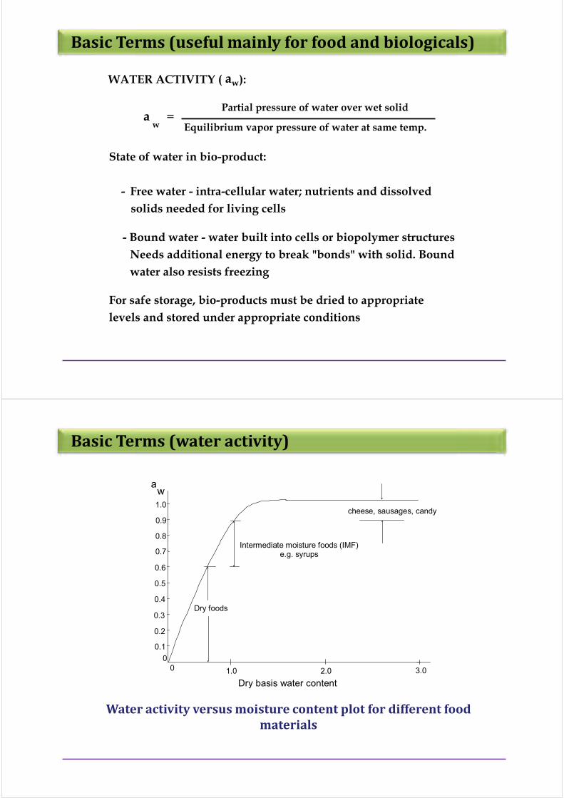
Basic Terms (useful mainly for food and biologicals)
WATER ACTIVITY ( a ): w
State of water in bio-product:
- Free water - intra-cellular water; nutrients and dissolved
solids needed for living cells
- Bound water - water built into cells or biopolymer structures
Needs additional energy to break "bonds" with solid. Bound
water also resists freezing
For safe storage, bio-products must be dried to appropriate
levels and stored under appropriate conditions
wa =
Partial pressure of water over wet solid
Equilibrium vapor pressure of water at same temp.
Basic Terms (water activity)
Dry foods
Intermediate moisture foods (IMF)
e.g. syrups
cheese, sausages, candy
aw
Dry basis water content
0
01.0 2.0 3.0
0.1
0.2
0.3
0.4
0.5
0.6
0.7
0.8
0.9
1.0
Water activity versus moisture content plot for different food
materials

Why so many dryer types?
• Over 500 reported in literature studies; over 100 commercially
available
• Over 50,000 materials are dried commercially at rates of a few kg/hr to
30 T/hr or more
• Drying times (residence times within drying chamber) can range from
1/3 sec. to months
• Temperature and pressure range from below triple point to super-
critical
• Numerous constraints on physical/chemical properties of feed as well
as dried product require a bewildering array of dryer designs
• Wide range of feeds (liquid, solid, semi-solid, particulate, pasty; sludge-
like; sticky etc); wide specs on dried product
Why so many dryer types?
• Different sources of energy input( conduction, convection, radiation,
MW,RF etc)
• Energy input continuous or intermittent
• Batch, continuous or semi-continuous operation
• Quality is key parameter for many products
• Limited number used in pharma industry
• Need to reduce the cost
• Need to consider drying system rather than dryer, i.e. Pre- and post-
drying stages are important and often cost more than dryer
• Environmental regulations demand new drying techniques

Dryer Selection
And classification
Criterion for selection of dryers
• Numerous criteria , with different weights
• Many dryers can typically meet specs; hence several dryers can do a
given job in general.
• Choice depends on mode of operation, physical form of feed and
dried product desired; heat sensitivity; quality requirements;
production rate; whether non-aqueous solvents are present in feed;
whether material is toxic/inflammable or friable etc
• Key criterion- dryer must be able to handle the product- move it
from feed to exit! Other criteria follow
• For pharma products -quality is NO 1 criterion!
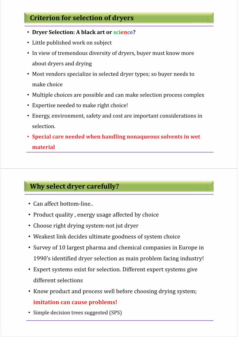
Criterion for selection of dryers
• Dryer Selection: A black art or science?
• Little published work on subject
• In view of tremendous diversity of dryers, buyer must know more
about dryers and drying
• Most vendors specialize in selected dryer types; so buyer needs to
make choice
• Multiple choices are possible and can make selection process complex
• Expertise needed to make right choice!
• Energy, environment, safety and cost are important considerations in
selection.
• Special care needed when handling nonaqueous solvents in wet
material
Why select dryer carefully?
• Can affect bottom-line..
• Product quality , energy usage affected by choice
• Choose right drying system-not jut dryer
• Weakest link decides ultimate goodness of system choice
• Survey of 10 largest pharma and chemical companies in Europe in
1990’s identified dryer selection as main problem facing industry!
• Expert systems exist for selection. Different expert systems give
different selections
• Know product and process well before choosing drying system;
imitation can cause problems!
• Simple decision trees suggested (SPS)
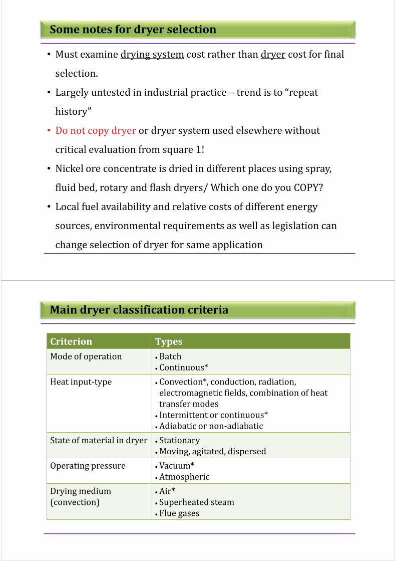
Some notes for dryer selection
• Must examine drying system cost rather than dryer cost for final
selection.
• Largely untested in industrial practice – trend is to “repeat
history”
• Do not copy dryer or dryer system used elsewhere without
critical evaluation from square 1!
• Nickel ore concentrate is dried in different places using spray,
fluid bed, rotary and flash dryers/ Which one do you COPY?
• Local fuel availability and relative costs of different energy
sources, environmental requirements as well as legislation can
change selection of dryer for same application
Main dryer classification criteria
Criterion Types
Mode of operation : Batch
: Continuous*
Heat input-type : Convection*, conduction, radiation,
electromagnetic fields, combination of heat
transfer modes
: Intermittent or continuous*
: Adiabatic or non-adiabatic
State of material in dryer : Stationary
: Moving, agitated, dispersed
Operating pressure : Vacuum*
: Atmospheric
Drying medium
(convection)
: Air*
: Superheated steam
: Flue gases

Main dryer classification criteria
Criterion Types
Drying temperature : Below boiling temperature*
: Above boiling temperature
: Below freezing point
Relative motion between
drying medium and
drying solids
: Co-current
: Counter-current
: Mixed flow
Number of stages : Single*
: Multi-stage
Residence time : Short (< 1 minute)
: Medium (1 – 60 minutes)
: Long (> 60 minutes)
* Most common in practice
Typical checklist for selection of industrial dryers
Physical form of feed : Granular, particulate, sludge, crystalline, liquid, pasty,
suspension, solution, continuous sheets, planks, odd-shapes
(small/large)
: Sticky, lumpy
Average throughput : kg/h (dry/wet); continuous
: kg per batch (dry/wet)
Expected variation in
throughput
(turndown ratio)
Fuel choice : Oil
: Gas
: Electricity
Pre- and post-drying
operations
(if any)
For particulate feed
products
: Mean particle size
: Size distribution
: Particle density
: Bulk density
: Rehydration properties

Typical checklist for selection of industrial dryers
Chemical/biochemical/
microbiological activity
Heat sensitivity : Melting point
: Glass transition temperature
Inlet/outlet moisture content : Dry basis
: Wet basis
Sorption isotherms
(equilibrium moisture
content)
Drying time : Drying curves
: Effect of process variables
Special requirements : Material of construction
: Corrosion
: Toxicity
: Non-aqueous solution
: Flammability limits
: Fire hazard
: Color/texture/aroma requirements (if any)
More guidelines for Dryer Selection

Principal Data Needed
Solids throughput Mass flow Ws
Turndown ratio
Moisture content Inlet X1,
Outlet X0, variation
Particle properties Size, size distribution
Density, rp, rs
Drying kinetics Drying curves
E.M.C. data
Temperature limits long-term
Instantaneous
Gas and solvent Identity
Physical properties
Other features Safety, ease of handling, attrition, etc.
Quality aspects
Toxicity, flammability
Include as much relevant data as possible
Additional Qualitative Data Needed
Fires and dust explosions
Toxicity
Potential for environmental damage
Product value
Need for containment
Capital cost
Attrition, hardness and friability
Cohesion, adhesion, agglomeration
Operating time
Need for size reduction/enlargement
Post-drying operations and Pre-drying factors

Small Scale Lab Tests
Small scale tests give valuable information:
• Drying kinetics – drying rates (parametric effects)
• Equilibrium moisture content – effect of T, humidity
• Microscopic examination – surface, agglomeration
• Lab-scale rotary evaporator – overheating, balling, adhesion
• Rotating drum tester – attrition, dustiness
• Cohesion and adhesion – handling, sticky point
• Vital to have a representative sample of final material
• Not necessary to carry out all of above tests in all cases
Basic Choice: Form of Feed
Feed and product can be in one of these main basic
forms:
• Particulate solids (bed/layer/or dispersed)
• Sheet or film
• Block or slab
• Slurry or solution (feed only) or paste
• Mostly require completely different types of dryer
• Widest choice available for particulate solids
• Specification of final product also critical in selection

Basic Choice: Batch or Continuous
Batch dryers favored by :
• Low throughput (under 50 kg/h)
• Long residence time (i.e. mainly falling rate drying)
• Batch equipment upstream and downstream
• Requirement for batch integrity
Continuous dryers favored by
• opposite conditions
Match production made of feed where possible
Basic Choice: Information From Kinetic Data
Interpretation of drying curves assists choice:
• Unhindered drying period – favors convective/dispersion
• Long hindered drying period – favors contact drying
• Estimate of required solids residence time
• Maximum likely drying rate
• Indication of mechanisms controlling drying
• Difference between initial and final drying rates *
* (If high, favors well-mixed, parallel flow or two-stage)
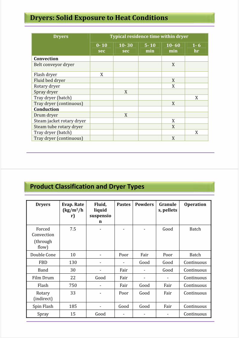
Dryers: Solid Exposure to Heat Conditions
Dryers Typical residence time within dryer
0- 10
sec
10- 30
sec
5- 10
min
10- 60
min
1- 6
hr
Convection
Belt conveyor dryer X
Flash dryer X
Fluid bed dryer X
Rotary dryer X
Spray dryer X
Tray dryer (batch) X
Tray dryer (continuous) X
Conduction
Drum dryer X
Steam jacket rotary dryer X
Steam tube rotary dryer X
Tray dryer (batch) X
Tray dryer (continuous) X
Product Classification and Dryer Types
Dryers Evap. Rate
(kg/m2/h
r)
Fluid,
liquid
suspensio
n
Pastes Powders Granule
s, pellets
Operation
Forced
Convection
(through
flow)
7.5 - - - Good Batch
Double Cone 10 - Poor Fair Poor Batch
FBD 130 - - Good Good Continuous
Band 30 - Fair - Good Continuous
Film Drum 22 Good Fair - - Continuous
Flash 750 - Fair Good Fair Continuous
Rotary
(indirect)
33 - Poor Good Fair Continuous
Spin Flash 185 - Good Good Fair Continuous
Spray 15 Good - - - Continuous

Different Industrial Dryer Types
Turbo Tray Dryers
! Suitable for granular feeds, operate with rotating shelves and force
convection of air above the shelves.
! The Dryer can have 30+ trays and provide large residence time.
! Hermetic sealing is possible for solvent recovery.

Rotary Dryer
! Combined cascade motion
with heat & mass transfer.
! Large capital & operating cost.
! Used in fertilizers,
pharmaceutical, lead & zinc
concentrate for smelting,
cement.
! Size 0.3 to 5 m diameter &
2 to 90 m length.
Steam Tube Rotary Dryer

Fluid Bed Dryers - Variations
Fluid Bed Dryers - Modifications
Homogeneous FB without channeling or bubbles;
high gas velocity possible
Deeper bed depth is possible if the bed is
agitated-Not commonly used
! Centrifugal / rotating FB - flowing
gas radially - rotating cylindrical
perforated distributor.
! promising contacting Umf and Ut
can be controlled

Rotocone Dryers (Batch)
! Drying of pharmaceuticals - tableting formulation
!Maximum capacity 10 m3.
! Evaporation rate 2-7 kg/hr.m2
Microwave Dryers
Used in ceramics industries,
foods & pharmaceuticals to
drive off final traces of
moisture.

Vacuum Dryers – Heat Sensitive Materials
Paddle Dryer
! Provides drying time
upto several hours.
! Suitable for pastelike &
granular material.
! Evap. rate upto 10 kg/hr.m2

Screw Conveyor dryer
! Use to dry variety of materials
! Can be use as conveyor + dryer
! Possibility of conductive heating, use of sub atmospheric pressure
Yamato TACO Rotary Dryer

Superheated Steam Drying
Closed steam
drying system
Recycled steam
Fan/blower
Direct use of
steam
Energy recovery via
heat exchanger
Removal of
condensate
Heater
purged steam
steam from boiler
Typical SSD set-up
Superheated Steam Drying
Saturated Steam Feed
Assume 100°C, 1 bar; H =
2,690 kJ/kg
Steam
Superheater
Superheated Steam
Assume 110°C, 1 bar; H = 2,720 kJ/kg
Drying chamber
Saturated Steam Exhaust
Back to 100°C, 1 bar; H = 2,690 kJ/kg
Bleeding off for
other uses

Superheated Steam Drying
Superheated
Steam Dryers
Low pressure
Near
atmospheric
pressure
High Pressure
Example: potato chip,
tortilla chip, shrimp,
paddy, soybean, noodles
Example: Beet pulp
Example: products
which trend to melt or
undergo glass transition
Classification of SSD
Superheated Steam Drying
• Flash dryers with or without indirect
heating of walls
• FBDs with or without immersed heat
exchangers
• Spray dryers
• Impinging jet dryers
• Conveyor dryers
• Rotary dryers
• Impinging stream dryers
Fluid bed
Possible Types of SSD

Selection of Fluid Bed Dryer
Fluidization Regimes
1. Depends on types
of solids,
fluidization can
appear in different
types of regimes
2. Smooth fluidization
and bubbling
fluidization are
preferable
3. Any material that
can be fluidized in
these two regimes
can be dried in a
FBD
4. By modifications of
FBD, some solids /
powders / pastes /
solutions / sheets
can also be
fluidized wellIncreasing gas velocity

Developments in Fluidized beds
! Conventional FBD’s use steady flow rate, constant temperature and operate
in batch or continuous mode at near atmospheric pressure with air as the
drying/fluidizing medium
! Modified FBDs may use pulsed flow, variable temperature, vibration to assist
fluidization, use superheated steam as drying medium, operate at reduced
pressure etc.
! FBDs may be used to dry slurries or continuous sheets (e.g. leather in a bed
of adsorbent particles)
! Fluidized beds compete with rotary dryers, conveyor dryers and moving bed
or packed bed dryers due to their advantages such as higher efficiency, better
heat/mass transfer rates, smaller floor area; ability to operate in batch or
continuous modes etc
! Limitations include high power consumption, attrition, need to have
fluidizable material etc
! Often a second stage after flash drying or spray drying where it is also used
as an agglomerate
Comparison of FBD with other dryers
Large range
Flexible
Up to 60min
Large
Large
High
High
High
Medium
Low
High
Fines
Limited
10-30sec
Large length
Small
High
Low
Medium
Medium
Medium
Medium
500"m-10mm
Flexible
Up to 120min
Large
Small
Low
Low
Medium
High
High
Medium
100-2000"m
Limited
Up to 60min
Small
Small
High
Medium
Medium
High
High
Medium
Particle size
PS Distribution
Drying time
Floor area
Turndown ratio
Attrition
Power consumption
Maintenance
Energy efficiency
Ease of control
Capacity
10"m-10mm
Wide
Up to 60min
Small
Small
High
Medium
Medium
High
High
High
Criterion Rotary Flash Conveyor FBD Modified
FBD

FBD Classification
Criterion Types of FB Dryer
Mode
Flow regime
Pressure
Temperature
Gas flow
Heat supply
Fluidization action
Fluidizing material
Fluidizing medium
Batch, continuous, semi continuous
Well mixed, plug flow, circulating, hybrid
Low (heat sensitive), atmospheric, high (steam)
Constant, time dependant
Continuous, pulsed
Convection/conduction; continuous/pulsed
Gas flow, jet flow, mechanical, external field
Particulate solids, paste slurry (inert solids
bed)
Heated air, s. steam, dehumidified air, freeze
FBD Classification
FB Dryers
Batch Continuous
HybridContinuous
input
Variable
input
MultistageSingle stage
Conventional ConventionalModified Modified
Batch (Well Mix) Plug Flow (narrow RTD) Well Mix (wide RTD)

FBD Classification
FB Dryers
Batch Continuous
Continuous input Variable input
Conventional Modified
Spout FBD
Pulsating FBDAgitated
FBD
Baffled FBD
Inert solid
FBD
FBD Classification
FB DryersBatch
Continuous
Single stage Multistage Hybrid
Conventional Modified
Immersed tubes
Vibrating FBD FB dryer cooler Spray FBD
Cyclone FBDWell mixed-Plug flow
Plug flow FBD
Well mix
FBD

Well Mixed and Plug Flow Fluid Bed dryer
! common FBD used in industry.
! bed temperature uniform, equal to the product and exhaust gas
temperatures.
! particle residence time distribution is wide
! wide range of product moisture content.
! feed is continuously charged into FB of relatively dry particles,
this enhances fluidization quality.
! a series of well-mixed continuous dryers may be used with
variable operating parameters.
! vertical baffles are inserted to create a narrow particle flow
path.
! narrow particle residence time distribution.
! nearly equal residence time for all particles regardless of their
size
! uniform product moisture content.
! length-to-width ratio from 5:1 to 30:1.
! inlet region may be agitated or apply back-mixing, or use a
flash dryer to remove the surface moisture.
Multi-stage / Multi Process FBD
! Fluidized bed drying: heated air
! Fluidized bed cooling: cold air
! Well-mix fluidized bed - plug flow fluidized
bed
! Drying: Well-mix - pre-dryer; Plug flow -
second stage drying.
Fluidized Bed Dryer/Cooler
Combines FB drying and cooling.
Cooling to eliminate condensation

Multi-stage / Multi Process FBD
upper stage drying - lower stage cooling well–
mixed FB - plug flow FB
Spray drying
FB drying,
FB cooling
spray drying - well–mixed
FB drying/cooling - plug flow
FBD Variations
! Variable operating parameters: pulsating gas flow,
variable temperature, adjustable heat input or periodic
fluidization
! energy and cost effectiveness
! Pulsating – provides vertical vibration, improving the
fluidization quality
! Bed temperature - batch FB - constant - adjustable heat
input
! Pulsating FB –rotated hot air inlet – intermittent drying
times
Pulsating Fluidized Bed
! low energy consumption due to high specific moisture
extraction rate (SMER)
! high coefficient of performance (COP)
! wide range of drying temperature (-20oC to 110oC)
! environmental friendly
! high product quality.
! suitable for heat sensitive products (food, bio-origin
products.
Fluid Bed Heat Pump Dryer

Selection of Spray Dryer
Components of Spray Dryer
A conventional spray drying process consists of the following four stages:
1. Atomization of feed into droplets
2. Heating of hot drying medium
3. Spray-air contact and drying of droplets
4. Product recovery and final air treatment
Figure: Typical spray dryer layout

Types of atomizers: Rotary atomizer
Advantages:
" Handles large feed rates with single
wheel or disk
" Suited for abrasive feeds with proper
design
" Has negligible clogging tendency
" Change of wheel rotary speed to control
the particle size distribution
" More flexible capacity (but with changes
powder properties)
" Limitations :
" Higher energy consumption compared
to pressure nozzles
" More expensive
" Broad spray pattern requires large
drying chamber diameter
Types of atomizers: Pressure nozzle
Advantages:
" Simple, compact and cheap
" No moving parts
" Low energy consumption
Limitations:
" Low capacity (feed rate for single nozzle)
" High tendency to clog
" Erosion can change spray characteristics

Types of atomizers: Pressure nozzle
Advantages:
" Simple, compact and cheap
" No moving parts
" Handle the feedstocks with high-viscosity
" Produce products with very small size particle
Limitations:
" High energy consumption
" Low capacity (feed rate)
" High tendency to clog
Types of Spray Dryers-flow patterns
Co-current flow Counter-current flow Mixed-current flow

Selection Tree for Spray Drying System
Energy Aspects in Drying

Why Energy Saving Needed ?
! Rising energy costs- may even end up with carbon tax
! Greenhouse gas emission related directly to energy consumed
! Industrial dryers operate at 20-70% efficiency- lot of scope to improve
operation
! Globalization will force competition
! This part includes global energy status, Energy in Drying….
! possible options for energy savings in general way (Not specific criteria)
General observations
! Drying- a highly energy-intensive operation due to
1. High vaporization latent of water
2. Affinity of solids to water
3. Difficulty in getting heat to where water is; resistances to heat/ mass
transfer, etc
! Some obvious options to save energy
1. Avoid drying –not feasible !
2. Displace water with solvent with low heat of vaporization and high
vapor presence
3. Use mechanical means (filtration, ultra-centrifugation, etc)
4. Use evaporation (for dilute liquids)

Some indices used to define dryer efficiency
! Energy efficiency ;
! Energy efficiency ;T (range from 0 to 1)
! T1= Inlet air temperature; T2= Outlet air temperature; T0=Ambient
temperature
dryertogivenenergyTotal
nevaporatiomoistureforusedEnergy
E
E#
t
ev !!
01
21T
TT
TT#
""
!
! Max ;T is when T2=Twb
Twb= wet bulb temperature at exit conditions
Think Drying System instead of Dryer !!
! Always look at full flowsheet - and the whole drying system - not just dryer!
! Pre-drying ( mechanical dewatering etc) and post-drying ( cooling,
granulation, blending etc) should be considered in overall strategy to save
energy
! Mechanical dewatering is 10 times cheaper than evaporation which is 10
times cheaper than drying ! (Rough rules of thumb!)
! Not always possible to use minimum energy option as it may not be optimal
for quality etc.

Techniques for energy savings
! How energy is produced for drying- direct firing is most efficient;
convective drying can be more rapid
! Electric heating technologies- some new technologies have emerged to be
cost-competitive
! Heat recovery- various options
! Control of dryer
! New developments e.g. superheated steam pulsed combustion, adsorption
drying etc.
Direct firing-why?
! CDDET recommends direct drying with natural gas to reduce chain of heat
transfer equipment. Claims advantages such as:
! Reduced maintenance; Ease of installation
! Uniform heating, better control of temperature
! Potential for integration into existing control system.
! Loss of energy in exhaust air
! Heat recovery from low temperature exhaust is not inexpensive
! Product maybe contaminated by combustion gas; not allowed in some
countries for foods
! Flammable solids/vapors require self-inertizing (low oxygen atmosphere).
Limitations

Electric Heating
! Higher grade energy-typically an expensive source for low grade heat; use
only if there is quality advantage
! MW drying can be more energy-efficient than solar energy in energy
consumed, not cost-effective always look at bottom-line!
! IR heating, MW/RF, induction heating can deliver energy direct to product-
no air needed- hence more efficient thermally.
! Precise temperature control
! Reduced dryer size
! Clean, easy-to-maintain
! Better quality, no contamination
! Short start-up, shut-down times.
Advantages
Heat recovery
! Recycle ratio of exhaust air, if drying rates are high due to high air
velocity and short contact time in dryer e.g. Yankee dryer for tissue
paper- 80-90% of exhaust needs to be recycled!
! Consider cost associated with recycle ducting and some reduction in
driving potential for drying
! Can cause problems of condensation etc as weather changes
significantly.

Use of Process Control
! Refer to chapter on Control of Dryers in
Handbook of Industrial Drying, 3rd Edition for
details of control strategies
! Here we look only at potential for energy
savings
! % Energy savings depends on the quality of
base case used!!.
Use of Process Control
! Refer to chapter on Control of Dryers in
Handbook of Industrial Drying, 3rd
Edition for details of control strategies
! Here we look only at potential for energy
savings
! % Energy savings depends on the quality
of base case used!!.

Some heat recovery methods
! Use of heat pumps
! Heat Pipe heat exchangers
! Gas/gas plate heat exchangers; fin-tube exchangers
! Heat Wheels- can have short paybacks
! Control- improve quality, reliability, energy consumption etc
! Good housekeeping; good insulation etc.
Summary of case studies reported (Energy Recovery)
Sector Title Energy
savings
Payback Comments
Wood Hardwood
manufacturer uses
electric driven heat
pump to kiln dry
lumber
33% Not given Electric heat pump, lower
inventory costs due to
elimination of air drying
step, improved product
quality
Wood Lumber dry kiln
heat recovery
system
30% 2 years Heat pipe heat
exchanger system. No
remixing of exhaust and
inlet
Ceramics Saving energy with
heat pump at a
pottery
45%(cos
t saving)
Not given Electric heat pump
dehumidifier
Malt Electric heat pump
dehumidification
halved energy
costs
50% 2 years Electric heat pump
dehumidifier, improved
product quality

Summary of case studies reported (Energy Recovery)
Sector Title Energy
savings
Payback Comments
Ceramics Heat recovery from
spray dryer using a
glass tube heat
exchanger
20% 2 years Spray dryer exhaust gas
heat recovery
Food Heat recovery
using a run-
around coil in the
air and exhaust
system
25% Not given PVC coating on
exchangers to prevent
corrosion
Ceramics Waste heat
recovery in drying
towers in
manufacture of
detergents
2 years Exhaust heat recovery,
glass tube heat exchanger,
reduced fouling
General guidelines for saving energy
! Use indirect heating( Conduction, IR) to avoid loss of energy in exhaust air
! Use intermittent , multi-mode heating, where possible- for batch drying
! Use less air, higher temperature, where possible
! Use waste heat, renewable energy( solar, wind, etc), where feasible
! Recover exhaust heat or recycle
! Optimize operating conditions; model based control
! Some options involve extra capital costs

Energy Efficiency for Different Dryers
Dryer type ; range% Dryer type ; range%
Direct continuous Indirect continuous
Tower 20-40 Drum 60-75
flash 50-75 Rotary 50-60
Sheeting (stenters) 50-60 Cylinder 60-70
conveyor 40-60 Batch
Rotary (bundle) 40-70 Agitated pan 60-70
Spray 40-60 Vacuum rotary Up to 70
Tunnel 35-40 Vacuum tray 60-70
Fluidized bed 40-70 Infrared 50-80
Batch Dielectric 50-60
Tray 85
Methods to improve energy efficiency
Methods Potential
Use of heat exchangers including heat pipes M
Use of heat pumps M-L
Model-based control M-L
Optimized operation H-M
Superheated steam drying with utilization of
excess steam
L
Multi-stage drying M-L
More efficient heat source (e.g. pulse
combustion)
M-L
H: high M: medium L: low

How to save energy in drying?
! Do regular energy audits- find out where heat is being lost. Temperature
and humidity measurements at inlet, outlet ; IR thermography can help
detect leaks
! Typically 20-30% energy can be saved at no cost !
! Using advanced/modified drying systems
1. Superheated steam drying
2. Multi-stage drying system
3. Low pressure spray drying
4. Pulse combustion drying
Introduction to pulse combustion drying
! Pulse combustion is intermittent ; can be subsonic or supersonic Mach
Number >1.0 (supersonic)Features Steady Pulsed
Combustion intensity
(kW/m3)100-1000
10000-
50000
Efficiency of burning (%) 80-96 90-99
Temperature level ( K)2000-
2500
1500-
2000
CO concentration in
exhaust (%)0-2 0-1
NOx concentration in
exhaust (mg/m3)100-7000 20-70
Convective heat transfer
coefficient (W/m2k)50-100 100-500
Time of reaction (s) 1-10 0.01-0.5
Excess air ratio 1.01-1.2 1.00-1.01
http://blastwavejet.com/pulsejet.htm

More about pulse combustion drying
! High drying rates
– Increased turbulence and flow reversal in the drying zone promote
gas/materials mixing
– Decreased boundary layer thickness of materials
– Increased heat and mass transfer rates
– High driving force because of high gas temperature
! short contact time
– Suitable for some heat sensitive materials
! High energy efficiency and economic use of fuels
! Environmentally friendly operation
Energy consumption between PC and conventional dryer
DryersTypical evaporation
capacity
Typical consumption
(kJ/kgH2O)
PC dryers 250-2000 kg H2O/h 3000-3500
Tunnel dryer 5500-6000
Impingement
dryer50 kg H2O/hm2 5000-7000
Rotary dryer 30-80 kg H2O/hm2 4600-9200
Fluid bed dryer 4000-6000
Flash dryer 5-100 kg H2O/hm3 4500-9000
Spray dryer 1-30 kg H2O/hm3 4500-11500
Drum dryer
(pastes)6-20 kg H2O/hm2 3200-6500

Advanced Drying Methods
Heat Pump Dryer (Concept)
Ambient
airDehumidified
air
Drying
Hot air

Advanced Drying Methods
Typical Heat Pump Dryer
Advanced Drying Methods
Advantages and Limitations of Heat Pump Dryer
! High Energy Efficiency
! Better quality products
especially for heat sensitive
materials.
! Wide range of operating
conditions.
! Low temperature drying.
! Better solvent recovery in
closed loop system (useful for
recovering solvent during
drying of pharma products).
! Higher initial cost and maintenance cost due to need to maintain compressor, refrigerant filters and charging of refrigerant
! Leakage of refrigerant.
! Marginally complex operation relative to simple convection dryer.
! Additional floor space requirement.
Advantages Limitations

Advanced Drying Methods
More about Heat Pump Dryer
-40oC -25oC 0oC +90oC
Vacuum LT dryers HT dryers
Inert or immobilised particles
Liquid, solution,
frozen particles Solids and granules
Heat pump dryers
Fluidized or not
Advanced Drying Methods
More about Heat Pump Dryer
HEAT PUMP DRYERS
CLASSIFICATION
Processing
mode of dryer
Number of
drying
stages
Number of
stages of Heat
Pump
Auxiliary
heat input
Batch
dryer
Continuous
dryer
Single
drying
stage
Convection
Multiple -stage heat
pump dryer
cyclic
operation
Continuous
operation
Heat pump
dryer
operation
Conduction Others :
.Radio -Frequency
.Microwave
.INFRARED
intermittent
operation
multiple
drying
stage
single-stage heat
pump dryer
PRODUCT
TEMPERATUE
ABOVE
Freezing
POINT
BELOW
Freezing
POINT

Advanced Drying Methods
Atmospheric Freeze Drying
vibrator
Scope:
1. AFD with fixed bed
2. AFD with OD
3. AFD with vibrated bed
and absorbent
Advanced Drying Methods
Atmospheric Freeze Drying (Advantages)
! Significant reduction in energy costs - due to the absence of a vacuum chamber and ancillary
equipment .
! Continuous system - higher productivity and lower operating cost.
! Decrease energy consumption and drying time – due to application of heat-pump system and
different process temperature elevating modes.
! Minimize product degradation – by using inert gas drying environment.
! High heat transfer co-efficient - about 20-40 times grater than that in vacuum dryer.
! Long drying time – lower diffusivity of water vapor with increasing pressure in the chamber.
! Bulky system – Require more space.
! Two mechanical agents are required - does not seem economical from the energy point of
view.
! It also takes time to setup, de-humidify and cool the drying chamber.
Atmospheric Freeze Drying (Limitations)
!
!

Advanced Drying Methods
Spray freeze drying
! Method which combines
processing steps common to
freeze drying and spray drying
! The protein drug is dissolved
! Solution is nebulized into a
cryogenic medium (e.g. liquid
nitrogen) which generates a
dispersion of shock frozen
droplets
! Dispersion is then dried in
lyophilizer
! So far mainly used for highly
specialized food and pharma
products
Advanced Drying Methods
Microwave Dryer
! Microwave dryers are expensive
both in terms of the capital and
operating (energy) costs.
! They have found limited
applications to date.
! seem to have special advantages
in terms of product quality when
handling heat-sensitive materials.
They are worth considering as
! devices to speed up drying in the
tail end of the falling rate period.
Similarly, RF dryers have limited
industrial applicability
! Applications mainly in
food/pharma

Advanced Drying Methods
Intermittent Drying
Energy Savings & Quality Enhancement
Intermittent Drying
Batch - temporal Continuous - spatial
Cyclic or time-varying heat
input by convection,
conduction, radiation,
dielectric fields, etc.
Concurrent or sequential
Inherent
Rotary Dryers
Spouted Beds
Multi-cylinder
paper dryers
Imposed
Freeze Dryers
Wood Drying
Kilns
Pulsed Fluid
Beds
Advanced Drying Methods
Some examples of Intermittent Drying
Rotating Jet Spouted Bed dryer
Pulsed bed - intermittent fluidization
Vibrated bed with tempering periods
Intermittent IR/MW in a batch heat pump dryer
Conveyor (Apron) dryer with parts of the dryer
unheated
Aside from reduced energy/air consumption, product quality may
be better for heat-sensitive and/or fragile solids. Slight increases
in drying time are expected
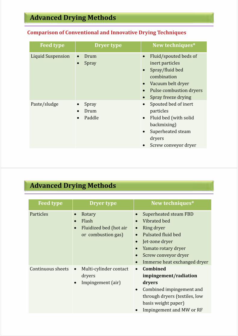
Advanced Drying Methods
Comparison of Conventional and Innovative Drying Techniques
Feed type Dryer type New techniques*
Liquid Suspension : Drum
: Spray
: Fluid/spouted beds of
inert particles
: Spray/fluid bed
combination
: Vacuum belt dryer
: Pulse combustion dryers
: Spray freeze drying
Paste/sludge : Spray
: Drum
: Paddle
: Spouted bed of inert
particles
: Fluid bed (with solid
backmixing)
: Superheated steam
dryers
: Screw conveyor dryer
Advanced Drying Methods
Feed type Dryer type New techniques*
Particles : Rotary
: Flash
: Fluidized bed (hot air
or combustion gas)
: Superheated steam FBD
: Vibrated bed
: Ring dryer
: Pulsated fluid bed
: Jet-zone dryer
: Yamato rotary dryer
: Screw conveyor dryer
: Immerse heat exchanged dryer
Continuous sheets : Multi-cylinder contact
dryers
: Impingement (air)
: Combined
impingement/radiation
dryers
: Combined impingement and
through dryers (textiles, low
basis weight paper)
: Impingement and MW or RF

Advanced Drying Methods
Developments in fluid bed drying (comparison innovative and
conventional fluidized beds)
Variant Conventional Innovative
Mode of heat
transfer
Only convection Convection + conduction
(immersed heaters in bed) +
radiative heat transfer (MW
assisted fluid beds)
Gas flow Steady Pulsating; on/off
Mode of fluidization Pneumatic Mechanically agitated /
vibrations
Drying media Air / flue gases Superheated steam / heat
pump assisted (even using
inert media)
Type of material
dried
Particulate material Drying of pastes / slurries
using bed of inert particles
Advanced Drying Methods
Hybrid Drying Technologies
Fluidized bed
dryers
Combined
mode of heat
transfer
Convective / conduction
(Agitated fluid bed dryer)
Convective with MW/RF/IR
Continuous or intermittent
Each stage with same dryer type
(Two-stage fluid bed)
Different dryers at each stage
(Spray and fluid bed dryer or
flash and fluid bed dryer)
Multi-stage
drying
systems
Multiprocess
ing dryers
Different drying technologies
at each stage (superheated
steam drying / by air drying)
Filter cum dryer
Drying and agglomeration (spray
followed by fluid bed)
Drying & cooling (in plug flow
fluid bed dryer

Closure
! Very important step (after establishing need to dry and optimal flow sheet
for non thermal dewatering)
! Wrong choice leads to severe penalties – start-up costs, downtime and need
to replace
! User must do “homework” fist; vendors valuable thereafter
! Several dryers may do the job – same quality, cost etc.
! Selection does depend on cost of fuel, relative cost of different energy
sources; geographical location; legislative regulations; emission control;
safety, etc.
! Consider new technologies as well – when available and proven
! Expert systems now available (e.g. SPS) to aid in selection – still a
combination of art (experience) and science!
! Selection may be dominated by just one criterion in some cases e.g. quality
for pharma products
! Several different dryers can do same job at same cost in some cases
! Choice can depend on geographic location, cost of energy etc
Closure
! Energy is a important point to be considered in drying which is highly
energy intensive unit operation
! Different routes can be used to minimize the energy losses
! Carbon foot prints can be minimized by making the drying system energy
efficient
! Developing energy intensive methods with sustainability – need to develop
innovative drying techniques
! Some of the advanced/innovative ways of drying are discussed

Books /monographs by Prof.
Arun S. Mujumdar
During 2010
Visit us at:
http://serve.me.nus.edu.sg/arun
Selected books and journals in
drying and transport phenomena
edited / authored by Prof. Arun
S. Mujumdar,
Visit us at:
http://serve.me.nus.edu.sg/arun

Visit us athttp://serve.me.nus.edu.sg/arun/ http://www.mujumdar.net78.net/