me 455- vehicle dynamics and control active safety control systems: tcs, abs, acc human driver...
TRANSCRIPT

ME 455- Vehicle Dynamics and Control
Active Safety Control Systems: TCS, ABS, ACCHuman Driver Models for Vehicle Control Design
Assoc. Prof. Dr. Pinar BoyrazApril 2015

PART I: ACC, TCS and ABS

Cruise Control Outline
• Introduction to Cruise Control • CC Modeling• CC Simulation
• Introduction to Adaptive Control• ACC Modeling• ACC Simulation

Cruise Control System
• Input: buttons on the steering wheel, brake, clutch, gas pedal and feedback signal• Processor• Sensor• Output: the throttle position

Modeling
Newton’s Second Law:
Laplace Transform:
mdv
dt b v t( ) u t( )
m s V s( ) b V s( ) U s( )

Transfer FunctionY s( )
U s( )
1
m s b

Design Specification
• Rise time < 5 sec• Overshoot < 10%• Steady-State Error < 2%
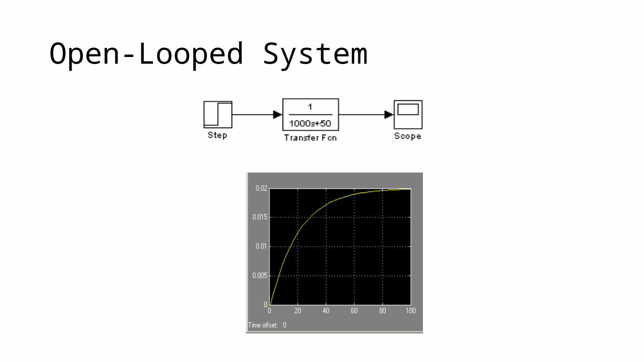
Open-Looped System

Closed-Loop w/ PI Control
Kp = 100 Kp = 800 and Ki = 40

Effect of weight of the car
m = 500 kg
PI Control: Kp = 800 and Ki = 40
m = 2000 kg

Adaptive Cruise Control
• So-called Active Cruise Control (ACC)• Traffic flow characteristics• Collision-avoidance system• Not to be considered as a safety feature by automakers

Background
• First laser-based system – Toyota’s Progress, a compact luxury sedan, in 1998• First radar-based system – Nissan’s Cima 41LV-2, a luxury sedan• First American ACC model – Lexus’ LS 430, in 2000

Function
• Preset and maintain the car speed• Measure the distance to the preceding car and the
relative speed• Adjust the car speed accordingly• Maximum deceleration = 3.5m/s^2

Adaptive Cruise Control• Change gear automatically• Function properly in poor weather condition• Cannot pick up non-moving objects• Effective in the speed between 30km-180km/h

Two types of ACC
• Radar-Based System – Three overlapping radar-beams (76-77kHz)-- Detects moving object up to 120 m – work in poor weather conditions• Laser-Based System (lidar) – less expensive and easier to package – light beams are narrower than water droplet and snowflakes
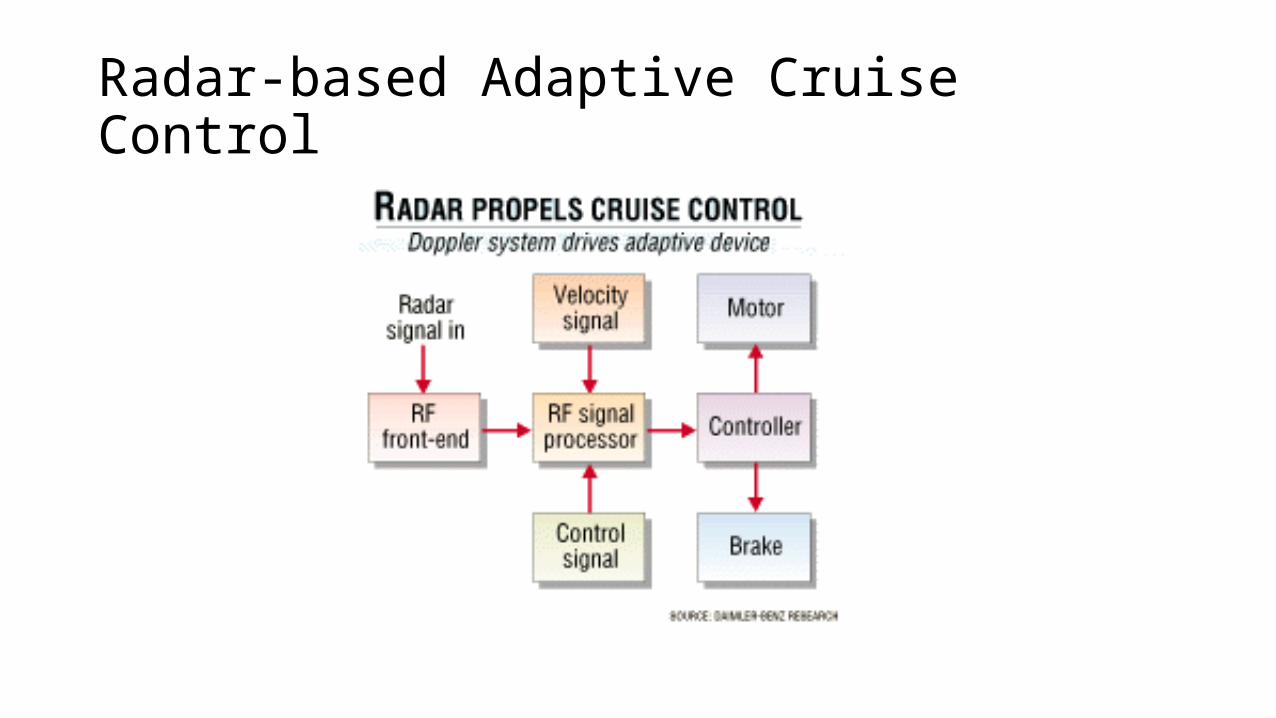
Radar-based Adaptive Cruise Control

Modeling in Highway Merging
By R. Sengupta and Q. Xu
ACC Controller
Desired Range
ades t( ) kv tr t( )d
d kp r t( ) rd t( )
rd t( ) 6.33v0.48 2

Highway Merge-In Scenario
• 1. At 0 sec, the preceding vehicle is traveling 12.5 m/s• 2. The follower vehicle w/ACC is 150 m behind the preceding vehicle
and is traveling at 25 m/s• 3. At 10 sec, the third vehicle cut in in between the two vehicles

Simulation in Highway Merging
By R. Sengupta and Q. Xu

Acceleration
Dotted Line = Desired AccelerationSolid Line = Actual Acceleration
By R. Sengupta and Q. Xu
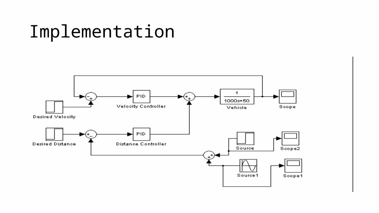
Implementation

Distance Source Distance Source
ACC Response CC Response (for comparison)

Antilock Brake System- Outline• Describe the reason for an antilock brake system (ABS)• Explain the theory of operation of ABS• Describe the parts of two-, three-, and four-wheel ABS• Explain the differences between integral and non-integral ABS• Explain how ABS provides traction control and stability enhancement• Explain ABS and normal brake warning light operation

Introduction
• Ability of brakes to do their job• Limited by tire grip to road surface• Skids could be avoided if driver could release brake pressure just before
wheel locks• When wheel stops turning, friction generates heat, causing tire to lose
traction• Slip rate of 50% means the wheel is rolling 50% slower than freely rolling tire• Maximum traction occurs at ten to twenty percent slip


Antilock Brakes
•Wheel speed sensors and computer •Monitor wheel speed•Wheel speed sensors measure rotational speed of the
wheel•Wheel locks: antilock brake controller pulsates the
pressure to that wheel• ABS is disabled below a certain speed• ABS senses failure: system reverts to conventional-only
braking• Pedal feel: bump followed by rapid pulsing

Antilock Brake System Components• Include:• ABS computer • Known as: electronic brake control module, controller
antilock brake, or electronic brake and traction control module
• Sensor inputs• Pressure modulator valves• Self-test•Wheel speed sensors • Variations and wiring
• Hydraulic control valve assembly


Types of Antilock Brake Systems• Integral ABS• Combine master cylinder, power brake booster, ABS
hydraulic circuitry in single assembly• Early systems used pump for pressure• Reservoir is usually much larger• Some systems have pressure sensitive switch
• Non-integral ABS• ABS unit is separate from master cylinder and is in series
with brake lines• Two or four wheel• One, three, or four-channel


Two-Wheel ABS
• Only works on rear wheels• Found on SUVs and light trucks• Designed to stop a fully loaded truck
• Rear brakes: modulated simultaneously• Centrally located, single sensor
• Four wheel ABS• Either three or four channel
• Four channel: sensor on each wheel• Front wheels controlled separately

Antilock Brake System Operation• During two-wheel ABS stop: isolation valve closes • Action by isolation solenoid not sufficient• Dump valve cycles open and closed rapidly
• Pressure to rear brakes is relieved and wheels are turning• Dump valve closes
• Three- and four-channel systems• Some use single combination valve
Antilock Brake System Operation (cont'd.)
• Nonintegral systems • May use motor pack
• Malfunction occurs in ABS system• Computer shuts system off
• When testing ABS • Pedal pulsing should be felt


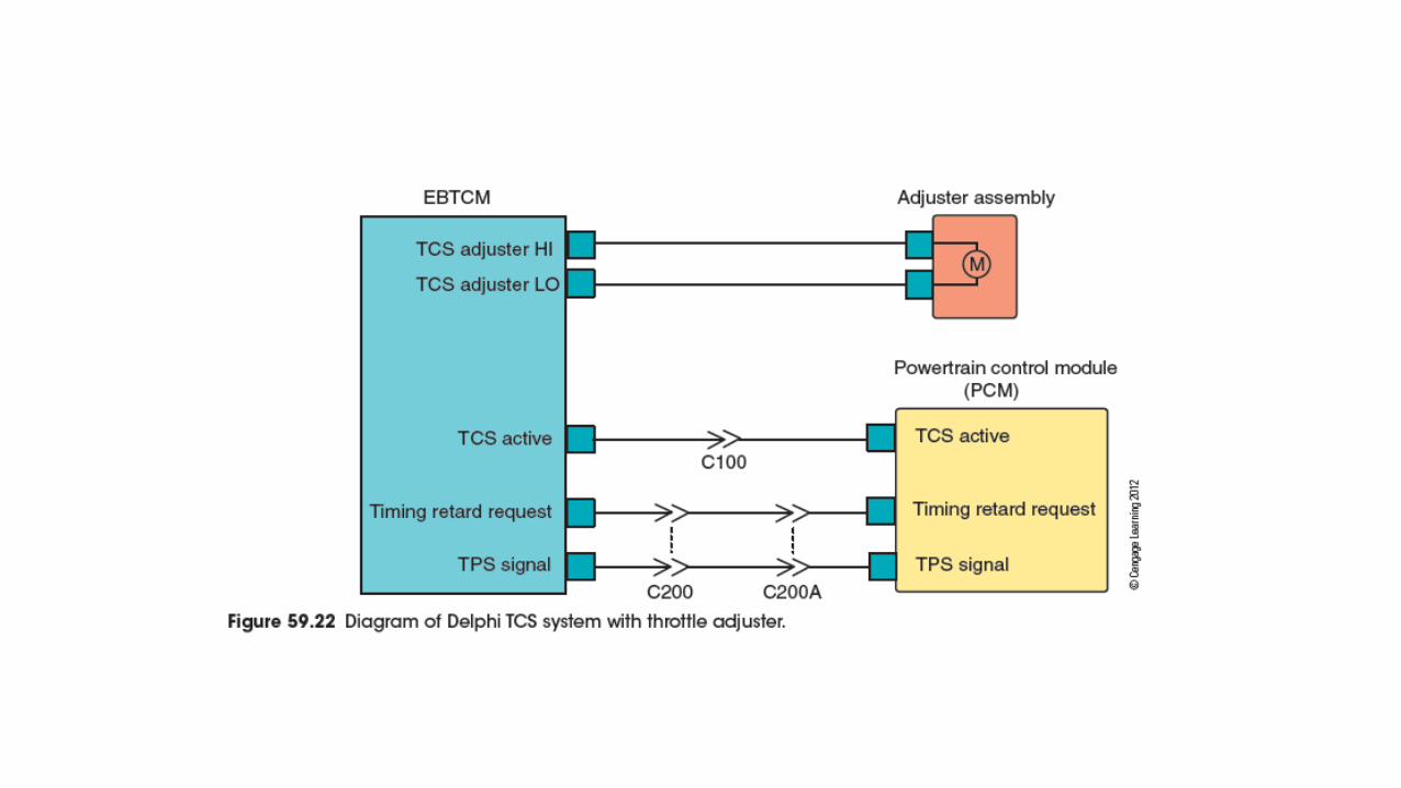
Traction Control System
• Traction control system (TCS) or acceleration slip regulation (ASR)• ABS limits wheel spin during acceleration
• Computer matches traction with engine power• Controller disables traction control if brakes overheat
• Electronic stability control• Computer stabilizes vehicle in sudden evasive maneuver
• Compensates for understeering and oversteering

PART II: HUMAN DRIVER MODELING

Human Factors and Driver Modeling

Human Factors and Driver Modeling

Human Factors and Driver Modeling

Human Factors and Driver Modeling

Human Factors and Driver Modeling

Human Factors and Driver Modeling

Human Factors and Driver Modeling

Human Factors and Driver Modeling

Human Factors and Driver Modeling

Driver Modeling

Driver Modeling

Driver Modeling

Driver Modeling

Driver Modeling

Driver Modeling

Driver Modeling

Driver Modeling- Example: Driver Handling Simulation

Driver Modeling- Example: Driver Handling Simulation
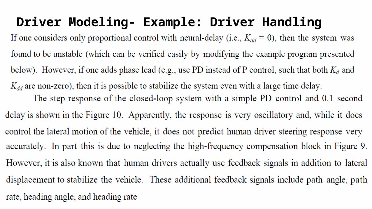
Driver Modeling- Example: Driver Handling Simulation

Driver Modeling- Example: Driver Handling Simulation

Driver Modeling- Example: Driver Handling Simulation- m file

Driver Modeling- Example: Driver Handling Simulation- m file

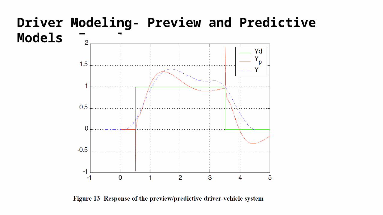
Driver Modeling- Preview and Predictive Models

Driver Modeling- Preview and Predictive Models

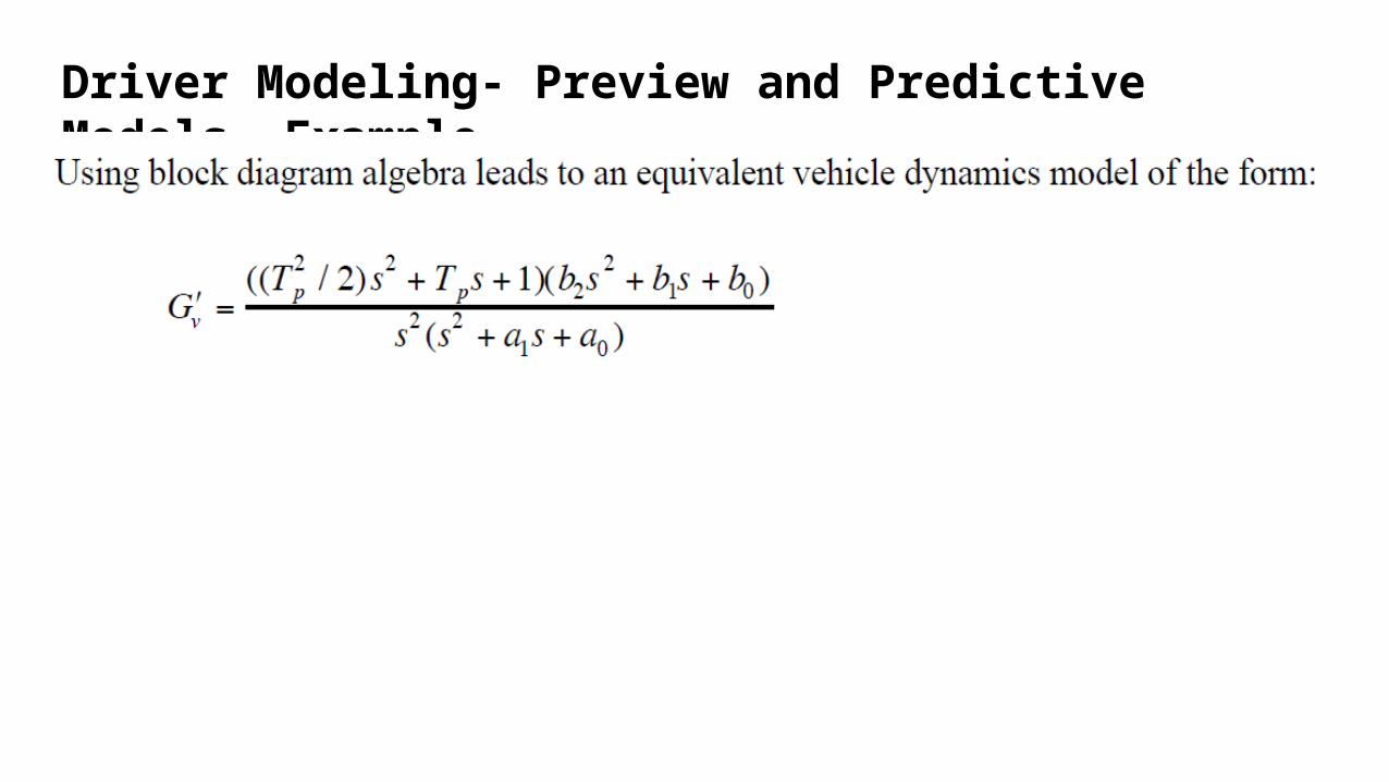
Driver Modeling- Preview and Predictive Models- Example

Driver Modeling- Preview and Predictive Models- Example

Driver Modeling- Preview and Predictive Models- Example
Driver Modeling- Preview and Predictive Models- Example
Driver Modeling- Preview and Predictive Models- Example

Driver Modeling- Preview and Predictive Models- Example m file

Driver Modeling- Longitudinal Models
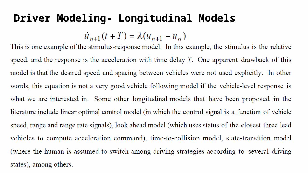
Driver Modeling- Longitudinal Models

NEXT WEEK:
MATLAB SESSION ON TRACTION CONTROL and ROLLOVER PREVENTION SYSTEMS
Source: