mcs-8 manual revision 4mcscontrols.com/documents/mcs/archived/manuals/mcs... · mcs-8 manual...
TRANSCRIPT
MCS-8 Manual Revision 4.10 Chiller & Condensing Units Software
(CHL V8 SW & V1.5 HW) The MCS Commitment Our commitment is to provide practical solutions for the industries needs and to be both a leader and partner in the effective use of microprocessor controls.
Micro Control Systems, Inc. 5877 Enterprise Parkway Fort Myers, Florida 33905
PH: (239) 694-0089 FAX: (239) 694-0031 www.mcscontrols.com
(Website contains product descriptions, manuals, software releases,
troubleshooting aids, etc)
Information contained in this manual has been prepared by Micro Control Systems, Inc. and is company confidential and copyright © protected 2007. Copying or distributing this document is prohibited unless
expressly approved by MCS.
MICRO CONTROL SYSTEMS REVISION 4.10
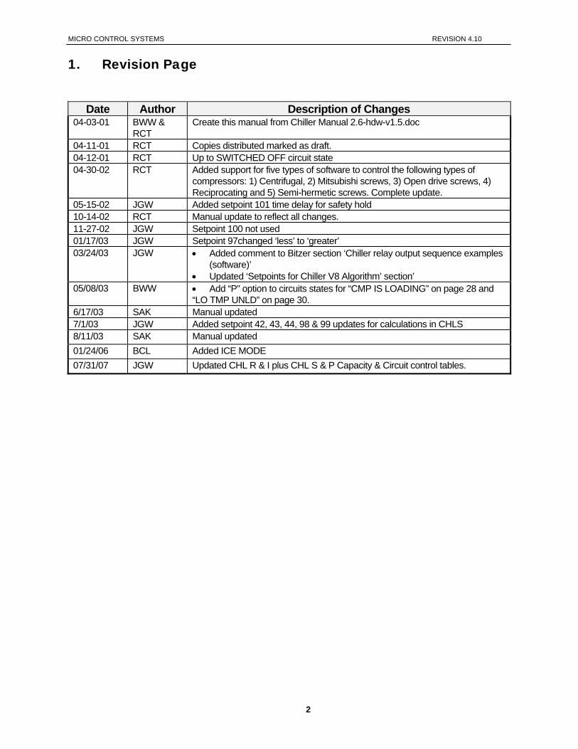
1. Revision Page
Date Author Description of Changes 04-03-01 BWW &
RCT Create this manual from Chiller Manual 2.6-hdw-v1.5.doc
04-11-01 RCT Copies distributed marked as draft. 04-12-01 RCT Up to SWITCHED OFF circuit state 04-30-02 RCT Added support for five types of software to control the following types of
compressors: 1) Centrifugal, 2) Mitsubishi screws, 3) Open drive screws, 4) Reciprocating and 5) Semi-hermetic screws. Complete update.
05-15-02 JGW Added setpoint 101 time delay for safety hold 10-14-02 RCT Manual update to reflect all changes. 11-27-02 JGW Setpoint 100 not used 01/17/03 JGW Setpoint 97changed ‘less’ to ‘greater’ 03/24/03 JGW • Added comment to Bitzer section ‘Chiller relay output sequence examples
(software)’ • Updated ‘Setpoints for Chiller V8 Algorithm’ section’
05/08/03 BWW • Add “P” option to circuits states for “CMP IS LOADING” on page 28 and “LO TMP UNLD” on page 30.
6/17/03 SAK Manual updated 7/1/03 JGW Added setpoint 42, 43, 44, 98 & 99 updates for calculations in CHLS 8/11/03 SAK Manual updated 01/24/06 BCL Added ICE MODE 07/31/07 JGW Updated CHL R & I plus CHL S & P Capacity & Circuit control tables.
2
MICRO CONTROL SYSTEMS REVISION 4.10
2. Table of Contents
1. Revision Page...........................................................................................................................................2
2. Table of Contents.....................................................................................................................................3
3. Introduction...............................................................................................................................................7 3.1. Introduction to MCS-8 CHL V8 Software Family ....................................................................................7 3.2. Common support items of the CHL V8 Software Family: ......................................................................7 3.3. CHL C 8.00- * supports Centrifugal Compressors: ................................................................................7 3.4. CHL H 8.00- * supports Heat Reclaim System:......................................................................................8 3.5. CHL I 8.00- * supports Ice Making System:............................................................................................8 3.6. CHL M 8.00- * supports Mitsubishi Screw Compressors:......................................................................9 3.7. CHL O 8.00-* supports Open Drive Screw Compressors: ..................................................................10 3.8. CHL P 8.00-* supports Semi-Hermetic Screw Compressors:.............................................................10 3.9. CHL R 8.00-* supports Fixed Step Capacity Compressors:................................................................10 3.10. CHL S 8.00-* supports Semi-Hermetic Screw Compressors:.........................................................10 3.11. CHL T 8.00-* supports TURBO COR Screw Compressors: ...........................................................11 3.12. About MCS-8 Hardware Support by CHL V8 Software Family .......................................................11 3.13. About this Manual...............................................................................................................................11 3.14. About the MCS-8................................................................................................................................11 3.15. About PC Support Software for MCS-8 ............................................................................................12 3.16. MCS 485 Network ..............................................................................................................................12
3.16.1. MCS 485 Network Local Pc Support Only................................................................................13 3.16.2. MCS 485 NETWORK REMOTE PC SUPPORT ONLY..........................................................14
4. Requirements for PC Software ............................................................................................................15
5. MCS-8 Control Zone Control Method Option.....................................................................................16 5.1. Common Definitions...............................................................................................................................16
5.1.1. Target ..........................................................................................................................................16 5.1.2. Control Zone ...............................................................................................................................16 5.1.3. Controlling Sensor ......................................................................................................................16 5.1.4. The Rate Of Change Of The Control Input ...............................................................................16 5.1.5. Step Delay...................................................................................................................................16 5.1.6. Sensitivity ....................................................................................................................................16
6. MCS-8 Voltage SI Control Method .......................................................................................................17 6.1. Common Definitions...............................................................................................................................17
6.1.1. Targets, Stage Cut In Values.....................................................................................................17 6.1.2. Stage Cut Out Values.................................................................................................................17 6.1.3. Step Delay...................................................................................................................................17 6.1.4. Controlling Sensor ......................................................................................................................17
7. Standard Variable Step Control Method.............................................................................................18
8. MCS-8 Control States ............................................................................................................................20 8.1. Control Status Display (from the MCS-8 keypad) ................................................................................20 8.2. Control Status Display (from the PC-Connect program)......................................................................21
9. Capacity Control States ........................................................................................................................23
10. Circuit Control States ............................................................................................................................25
11. Condenser Control Logic......................................................................................................................29
3
MICRO CONTROL SYSTEMS REVISION 4.10
11.1. Condenser Introduction......................................................................................................................29 11.2. RO Step Condenser Cut In – Out Logic............................................................................................29 11.3. RO Step Condenser With Variable Speed Fan................................................................................30 11.4. Modulating Condenser.......................................................................................................................30
12. Setpoint Definitions ...............................................................................................................................31 12.1. Setpoint elements that can be viewed:..............................................................................................31 12.2. Setpoint Types:...................................................................................................................................31
12.2.1. SETPOINT..................................................................................................................................31 12.2.2. LOCKOUT...................................................................................................................................31 12.2.3. ALARM........................................................................................................................................31
13. Setpoints for Chiller V8 Algorithm.......................................................................................................32 13.1. Voltage SI Control Method setpoints #1-18 ......................................................................................32 13.2. Control Setpoints #1-12 (apply to all software).................................................................................32 13.3. Control Setpoints #9-20, #114 to 120 (supported in EXV S & CHL T)............................................33 13.4. Control Setpoints #13-17 (only supported in CHL C, O, R and S) ..................................................34 13.5. Control Setpoints #13-15 (only supported in CHL H software)........................................................34 13.6. Control Setpoints #13-15 (only supported in CHL I software) .........................................................35 13.7. Control Setpoints #13-17 (only supported in CHL M software) .......................................................35 13.8. Control Setpoints #18-24 ...................................................................................................................35 13.9. Setpoints for Capacity Control Logic .................................................................................................36 13.10. Setpoints for controlling Variable Step Compressors.......................................................................36 13.11. Setpoints for calculating slide position for Variable Step Compressors..........................................37 13.12. Setpoints for calculating FLA & % load for Variable Step Compressors.........................................37 13.13. Setpoints for Condenser Control .......................................................................................................37 13.14. Setpoints for System Testing.............................................................................................................38 13.15. Setpoints for Compressor Control .....................................................................................................38 13.16. Setpoints for Compressor Safeties....................................................................................................39 13.17. Setpoints for Chilled Water Pump Control ........................................................................................42 13.18. Setpoints for TurboCor Compressor Warnings (only supported in CHL T software).....................42 13.19. Setpoints for Unit Safeties..................................................................................................................42 13.20. Setpoints for VI control (only supported in CHL O software) ...........................................................43 13.21. Setpoints for Service Mode Indicator (applies only to CHL I, M and P software)...........................43
14. AUTHORIZATION FUNCTION...............................................................................................................44
15. Standard Control Options.....................................................................................................................45 15.1. General Options..................................................................................................................................45 15.2. Compressor Options ..........................................................................................................................45 15.3. Condenser Options ............................................................................................................................46 15.4. Chiller Barrel Heater Options.............................................................................................................46 15.5. Hot Gas Bypass..................................................................................................................................46
15.5.1. Support in CHL R & I (fixed step capacity) software ...............................................................46 15.5.2. Support in CHL C, H, O, P and S software...............................................................................46
15.6. Chilled Water Reset............................................................................................................................47 15.7. Two Expansions Valves Option - Screws Only ................................................................................47 15.8. Oil Equalization Option – supported in CHL C, H, O, S and T software .........................................47 15.9. Oil Cooler Option - supported in CHL C, H, O, S and T software ...................................................47 15.10. Oil Pump Control Option – supported in CHL C, H and O software ...............................................48 15.11. Oil Differential Calculation..................................................................................................................48 15.12. On/Off Switches..................................................................................................................................48 15.13. Low Suction Unloading & Holding.....................................................................................................49 15.14. High Discharge Pressure Unloading & Holding................................................................................49 15.15. High Discharge Temperature Unloading & Holding.........................................................................50
4
MICRO CONTROL SYSTEMS REVISION 4.10
15.16. High Ampere Unloading & Holding – supported in CHL I, M and R software ................................50 15.17. Low Water Temperature Unloading & Holding.................................................................................50 15.18. Energy Efficient Compressor Staging – Screw only.........................................................................51 15.19. Chilled Water Pump Control ..............................................................................................................51 15.20. Process Pump & Heat Exchanger Control (not supported in CHL M) ............................................52 15.21. Control Power Relay –No Stop..........................................................................................................52 15.22. Part Wind or Star Delta Starter ..........................................................................................................52 15.23. Low & High Ambient Shutdown.........................................................................................................52 15.24. English or Metric sensor readings .....................................................................................................53 15.25. Compressor Auto Rotation.................................................................................................................53 15.26. Compressor Anti-Cycle Logic ............................................................................................................53 15.27. Warning & Alarm Relay Outputs........................................................................................................54 15.28. Vi Port Control Logic (Open Drive Screw only).................................................................................54 15.29. Operating Schedules..........................................................................................................................54 15.30. High Temperature Warning for TUBRO COR (CHT 008-08)..........................................................55 15.31. Mod-Motor Limit Control For Flooded Chiller....................................................................................55 15.32. Compressor ........................................................................................................................................55 15.33. Exhaust Fan (This is only available in CHL S 08.02 – B or greater) ...............................................55 15.34. Ice Mode (This is only available in CHL S 08.11-A or greater)........................................................56
16. MCS-8 Alarms and Safeties ..................................................................................................................57 16.1. Introduction .........................................................................................................................................57 16.2. Information only alarms......................................................................................................................57
16.2.1. System generated alarms..........................................................................................................57 16.2.2. Alarms as a result of individual action .......................................................................................57 16.2.3. Alarms generated by the control algorithm ...............................................................................57
16.3. MCS-8 system alarms........................................................................................................................58 16.3.1. Alarms are generated by the MCS-8 control algorithm:...........................................................58
16.4. Setpoint safety alarms........................................................................................................................59 16.4.1. Introduction..................................................................................................................................59 16.4.2. Sensor inputs used in conjunction with MCS-8 setpoint safeties: ...........................................59 16.4.3. Setpoint safeties .........................................................................................................................60
17. MCS Control States Quick Reference - CHL C 8.00 Software.........................................................63
18. MCS Control States Quick Reference - CHL M 8.00 Software.........................................................64
19. MCS Control States Quick Reference – CHL O & H 8.00 Software ................................................65
20. MCS Control States Quick Reference – CHL R & I 8.00 Software .................................................66
21. MCS Control States Quick Reference – CHL S & P 8.00 Software .................................................67
22. OEM Factory Checkout Procedure......................................................................................................68 22.1. Visual Check.......................................................................................................................................68 22.2. Mcs Power On (Compressor Power off) ...........................................................................................68
23. Compressor relay output sequence examples (software)...............................................................69 23.1. HANBELL Compressor (CHL P & CHL S) .......................................................................................69 23.2. Centrifugal Compressor (CHL C) ......................................................................................................69 23.3. Mitsubishi Mono Screw (CHL M).......................................................................................................69 23.4. Screw Compressor With Oil (CHL O) ..............................................................................................69 23.5. Reciprocating Compressor (CHL R) ................................................................................................70 23.6. Reciprocating Compressor (2 unloaders & hot gas bypass) (CHL R) ........................................70 23.7. Reciprocating Compressor (1 unloader & hot gas bypass) (CHL R)............................................70 23.8. Scroll Compressor (CHL R) ...............................................................................................................70
5
MICRO CONTROL SYSTEMS REVISION 4.10
23.9. JE HALL Screw Compressor With Split-winding (CHL S) ..............................................................70 23.10. HITACHI Screw Compressor (CHL P & CHL S) .............................................................................71 23.11. HARTFORD Compressor (Vertical) (CHL P & CHL S)...................................................................71 23.12. Bitzer Compressor (CHL S, V08.01 & prior use Hanbell as COMP TYPE) ...................................71 23.13. TurboCor Compressor (CHL T).........................................................................................................72
24. The Micro Control Center Keypad Display Quick Reference- STATUS KEYS..............................73
25. The Micro Control Center Keypad Display Quick Reference-ENTRY KEYS .................................74
26. The Micro Control Center MCS-8 & I/O Quick Reference Sheet .....................................................75
27. Details of MCS-8 & I/O Key Items.........................................................................................................76
28. The MCS Sensors Quick Reference Sheet– Temp./Humd. Sensors ..............................................77
29. The MCS Sensors Quick Reference Sheet - Pressure Sensor & Digital inputs ...........................78
30. The MCS Trouble Shooting Quick Reference Sheet.........................................................................79
6
MICRO CONTROL SYSTEMS REVISION 4.10
3. Introduction
3.1. Introduction to MCS-8 CHL V8 Software Family
The CHL V8 SW refers to a family of five software versions that provides the control for various types of chiller and condensing units. The CHL V8 software varies based on the type of compressors used on the chiller or condensing units. The CHL V8 software family supports the following types of compressors: • Semi-hermetic Screws (Hanbell, Hartford, Hitachi, Century, Bitzer, Hall, etc.), • Open drive screws (Hartford, Mycom, Frick, Howden, etc.) • Centrifugal (Trane, Carrier, York, etc), • Mitsubishi screws, • Reciprocating & Scrolls This software family is designed to keep each type of system running at its most energy efficient level based upon the systems current load. The user is provided with the exact knowledge of what the system is doing by displaying meaningful control status state names. This together with history status of all the inputs and outputs plus alarm information, provided in simple English, provides excellent user and/or machine interface. All versions of software are designed to be proactive, that is to take corrective action to keep a safety condition from occurring and if a safety does occur, to attempt to restart the package when the system returns to normal. This approach eliminates most, if not all of the nuisance alarms that occur.
3.2. Common support items of the CHL V8 Software Family:
Circuits (compressors) up to 8, Steps per Circuit up to 4, Relay Outputs up to 48, Analog Outputs up to 6, Sensor Inputs up to 48, Setpoints up to 120, Alarms up to 60
3.3. CHL C 8.00- * supports Centrifugal Compressors:
This software supports Centrifugal Compressors types with inlet vanes to vary the capacity. The oil pump control is similar to the control of open drive screw compressors with external oil pumps. In the PC-Config program select Centrifugal Comp as the compressor type. Compressor start up procedure is as follows:
The system will insure that the oil pump has been started and that the oil pressure and temperature is at an acceptable level.
Compressor normal running procedure is as follows: In addition to the normal safeties the system will monitor the temperature of the refrigerant. If the temperature is low, the system will attempt to unload a capacity step to prevent the low refrigerant temperature safety from occurring.
Sample of relay out puts provided in “Circuit relay output sequence examples” Section.
7
MICRO CONTROL SYSTEMS REVISION 4.10
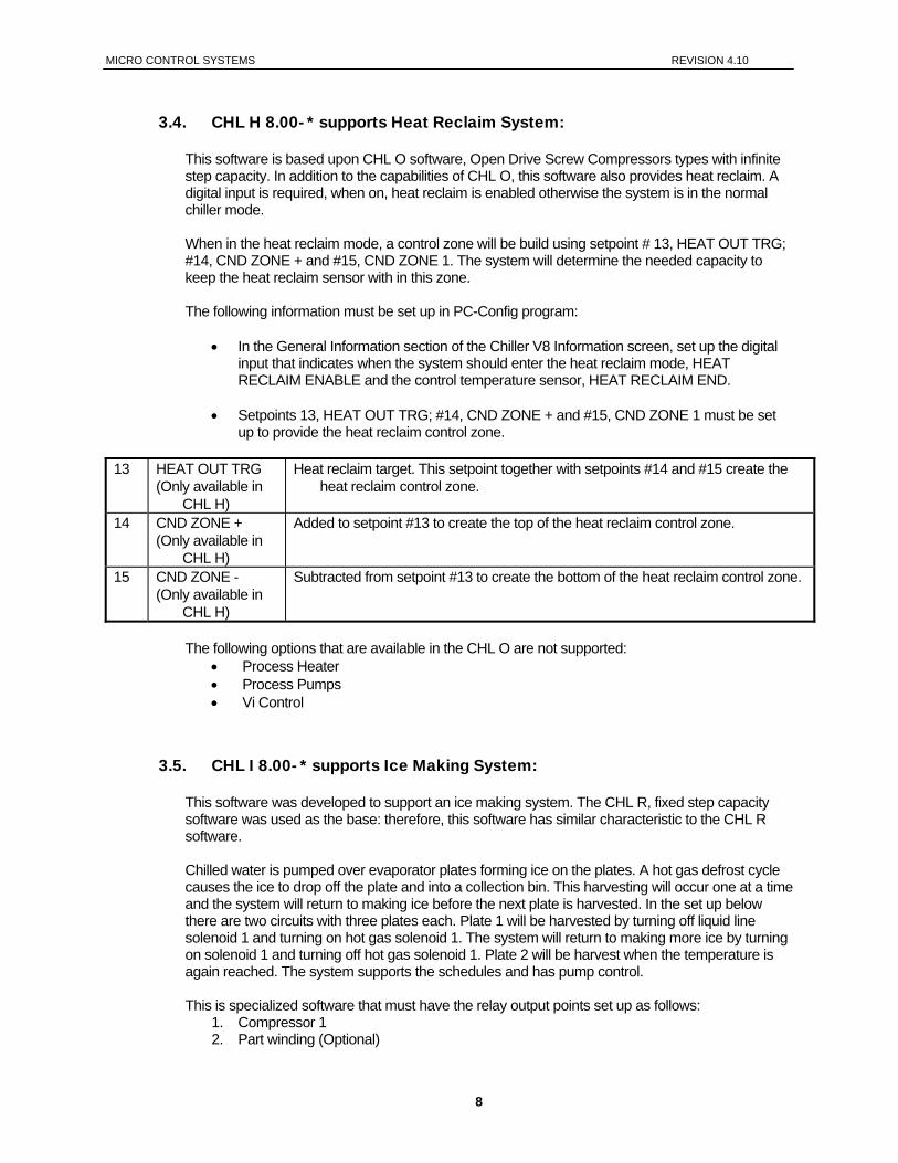
3.4. CHL H 8.00- * supports Heat Reclaim System:
This software is based upon CHL O software, Open Drive Screw Compressors types with infinite step capacity. In addition to the capabilities of CHL O, this software also provides heat reclaim. A digital input is required, when on, heat reclaim is enabled otherwise the system is in the normal chiller mode. When in the heat reclaim mode, a control zone will be build using setpoint # 13, HEAT OUT TRG; #14, CND ZONE + and #15, CND ZONE 1. The system will determine the needed capacity to keep the heat reclaim sensor with in this zone. The following information must be set up in PC-Config program:
• In the General Information section of the Chiller V8 Information screen, set up the digital input that indicates when the system should enter the heat reclaim mode, HEAT RECLAIM ENABLE and the control temperature sensor, HEAT RECLAIM END.
• Setpoints 13, HEAT OUT TRG; #14, CND ZONE + and #15, CND ZONE 1 must be set up to provide the heat reclaim control zone.
13 HEAT OUT TRG
(Only available in CHL H)
Heat reclaim target. This setpoint together with setpoints #14 and #15 create the heat reclaim control zone.
14 CND ZONE + (Only available in
CHL H)
Added to setpoint #13 to create the top of the heat reclaim control zone.
15 CND ZONE - (Only available in
CHL H)
Subtracted from setpoint #13 to create the bottom of the heat reclaim control zone.
The following options that are available in the CHL O are not supported:
• Process Heater • Process Pumps • Vi Control
3.5. CHL I 8.00- * supports Ice Making System:
This software was developed to support an ice making system. The CHL R, fixed step capacity software was used as the base: therefore, this software has similar characteristic to the CHL R software. Chilled water is pumped over evaporator plates forming ice on the plates. A hot gas defrost cycle causes the ice to drop off the plate and into a collection bin. This harvesting will occur one at a time and the system will return to making ice before the next plate is harvested. In the set up below there are two circuits with three plates each. Plate 1 will be harvested by turning off liquid line solenoid 1 and turning on hot gas solenoid 1. The system will return to making more ice by turning on solenoid 1 and turning off hot gas solenoid 1. Plate 2 will be harvest when the temperature is again reached. The system supports the schedules and has pump control. This is specialized software that must have the relay output points set up as follows:
1. Compressor 1 2. Part winding (Optional)
8
MICRO CONTROL SYSTEMS REVISION 4.10
3. Unloader 1 (Optional) 4. Unloader 2 (Optional) 5. Liquid line solenoid 1 6. Hot gas solenoid 1 7. Hot gas solenoid 2 8. Hot gas solenoid 3 9. Liquid line solenoid 2 10. Hot gas solenoid 4 11. Hot gas solenoid 5 12. Hot gas solenoid 6
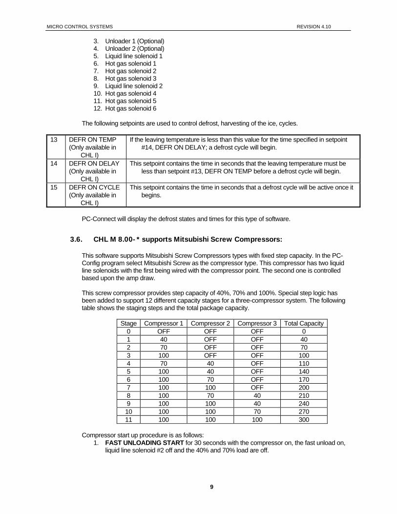
The following setpoints are used to control defrost, harvesting of the ice, cycles.
13 DEFR ON TEMP (Only available in
CHL I)
If the leaving temperature is less than this value for the time specified in setpoint #14, DEFR ON DELAY; a defrost cycle will begin.
14 DEFR ON DELAY (Only available in
CHL I)
This setpoint contains the time in seconds that the leaving temperature must be less than setpoint #13, DEFR ON TEMP before a defrost cycle will begin.
15 DEFR ON CYCLE (Only available in
CHL I)
This setpoint contains the time in seconds that a defrost cycle will be active once it begins.
PC-Connect will display the defrost states and times for this type of software.
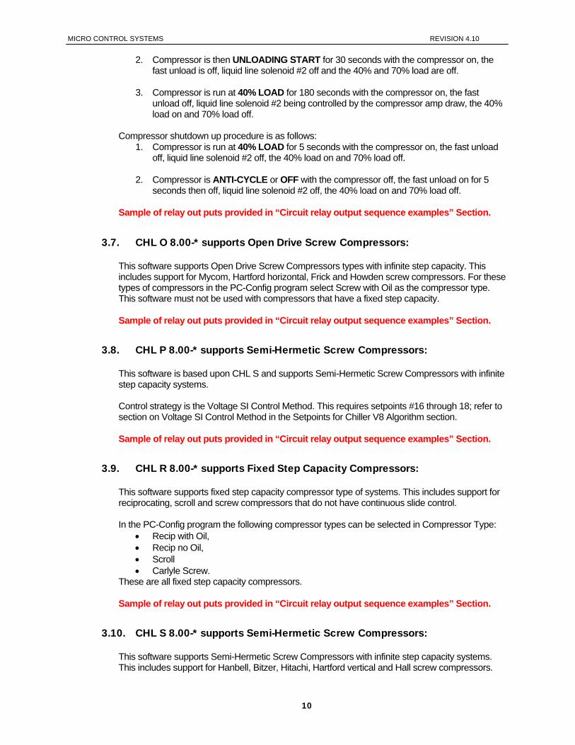
3.6. CHL M 8.00- * supports Mitsubishi Screw Compressors:
This software supports Mitsubishi Screw Compressors types with fixed step capacity. In the PC-Config program select Mitsubishi Screw as the compressor type. This compressor has two liquid line solenoids with the first being wired with the compressor point. The second one is controlled based upon the amp draw. This screw compressor provides step capacity of 40%, 70% and 100%. Special step logic has been added to support 12 different capacity stages for a three-compressor system. The following table shows the staging steps and the total package capacity.
Stage Compressor 1 Compressor 2 Compressor 3 Total Capacity 0 OFF OFF OFF 0 1 40 OFF OFF 40 2 70 OFF OFF 70 3 100 OFF OFF 100 4 70 40 OFF 110 5 100 40 OFF 140 6 100 70 OFF 170 7 100 100 OFF 200 8 100 70 40 210 9 100 100 40 240 10 100 100 70 270 11 100 100 100 300
Compressor start up procedure is as follows:
1. FAST UNLOADING START for 30 seconds with the compressor on, the fast unload on, liquid line solenoid #2 off and the 40% and 70% load are off.
9
MICRO CONTROL SYSTEMS REVISION 4.10
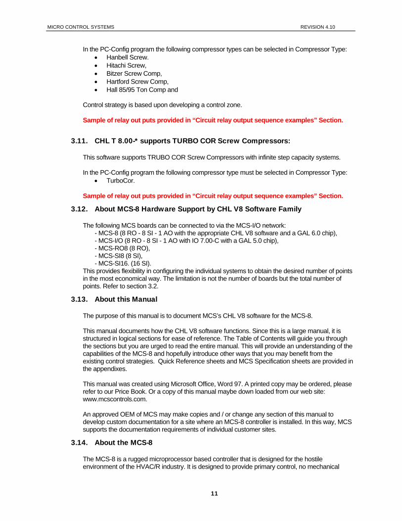
2. Compressor is then UNLOADING START for 30 seconds with the compressor on, the fast unload is off, liquid line solenoid #2 off and the 40% and 70% load are off.
3. Compressor is run at 40% LOAD for 180 seconds with the compressor on, the fast unload off, liquid line solenoid #2 being controlled by the compressor amp draw, the 40% load on and 70% load off.
Compressor shutdown up procedure is as follows:
1. Compressor is run at 40% LOAD for 5 seconds with the compressor on, the fast unload off, liquid line solenoid #2 off, the 40% load on and 70% load off.
2. Compressor is ANTI-CYCLE or OFF with the compressor off, the fast unload on for 5 seconds then off, liquid line solenoid #2 off, the 40% load on and 70% load off.
Sample of relay out puts provided in “Circuit relay output sequence examples” Section.
3.7. CHL O 8.00-* supports Open Drive Screw Compressors:
This software supports Open Drive Screw Compressors types with infinite step capacity. This includes support for Mycom, Hartford horizontal, Frick and Howden screw compressors. For these types of compressors in the PC-Config program select Screw with Oil as the compressor type. This software must not be used with compressors that have a fixed step capacity. Sample of relay out puts provided in “Circuit relay output sequence examples” Section.
3.8. CHL P 8.00-* supports Semi-Hermetic Screw Compressors:
This software is based upon CHL S and supports Semi-Hermetic Screw Compressors with infinite step capacity systems. Control strategy is the Voltage SI Control Method. This requires setpoints #16 through 18; refer to section on Voltage SI Control Method in the Setpoints for Chiller V8 Algorithm section. Sample of relay out puts provided in “Circuit relay output sequence examples” Section.
3.9. CHL R 8.00-* supports Fixed Step Capacity Compressors:
This software supports fixed step capacity compressor type of systems. This includes support for reciprocating, scroll and screw compressors that do not have continuous slide control. In the PC-Config program the following compressor types can be selected in Compressor Type:
• Recip with Oil, • Recip no Oil, • Scroll • Carlyle Screw.
These are all fixed step capacity compressors. Sample of relay out puts provided in “Circuit relay output sequence examples” Section.
3.10. CHL S 8.00-* supports Semi-Hermetic Screw Compressors:
This software supports Semi-Hermetic Screw Compressors with infinite step capacity systems. This includes support for Hanbell, Bitzer, Hitachi, Hartford vertical and Hall screw compressors.
10
MICRO CONTROL SYSTEMS REVISION 4.10
In the PC-Config program the following compressor types can be selected in Compressor Type:
• Hanbell Screw. • Hitachi Screw, • Bitzer Screw Comp, • Hartford Screw Comp, • Hall 85/95 Ton Comp and
Control strategy is based upon developing a control zone. Sample of relay out puts provided in “Circuit relay output sequence examples” Section.
3.11. CHL T 8.00-* supports TURBO COR Screw Compressors:
This software supports TRUBO COR Screw Compressors with infinite step capacity systems. In the PC-Config program the following compressor type must be selected in Compressor Type:
• TurboCor. Sample of relay out puts provided in “Circuit relay output sequence examples” Section.
3.12. About MCS-8 Hardware Support by CHL V8 Software Family
The following MCS boards can be connected to via the MCS-I/O network: - MCS-8 (8 RO - 8 SI - 1 AO with the appropriate CHL V8 software and a GAL 6.0 chip), - MCS-I/O (8 RO - 8 SI - 1 AO with IO 7.00-C with a GAL 5.0 chip), - MCS-RO8 (8 RO), - MCS-SI8 (8 SI), - MCS-SI16. (16 SI).
This provides flexibility in configuring the individual systems to obtain the desired number of points in the most economical way. The limitation is not the number of boards but the total number of points. Refer to section 3.2.
3.13. About this Manual
The purpose of this manual is to document MCS’s CHL V8 software for the MCS-8. This manual documents how the CHL V8 software functions. Since this is a large manual, it is structured in logical sections for ease of reference. The Table of Contents will guide you through the sections but you are urged to read the entire manual. This will provide an understanding of the capabilities of the MCS-8 and hopefully introduce other ways that you may benefit from the existing control strategies. Quick Reference sheets and MCS Specification sheets are provided in the appendixes. This manual was created using Microsoft Office, Word 97. A printed copy may be ordered, please refer to our Price Book. Or a copy of this manual maybe down loaded from our web site: www.mcscontrols.com. An approved OEM of MCS may make copies and / or change any section of this manual to develop custom documentation for a site where an MCS-8 controller is installed. In this way, MCS supports the documentation requirements of individual customer sites.
3.14. About the MCS-8
The MCS-8 is a rugged microprocessor based controller that is designed for the hostile environment of the HVAC/R industry. It is designed to provide primary control, no mechanical
11

MICRO CONTROL SYSTEMS REVISION 4.10
controls; interface with building management systems; communicate both locally and remotely. The MCS-8 provides flexibility with setpoints and control options that can be selected prior to commissioning a system or when the unit is live and functioning. Displays, alarms and other interfaces are accomplished in a clear and simple language that informs the user as to the status of the controller. The MCS-8 is designed to safeguard the system that is being controlled, eliminate the need for manual intervention and to provide a simple but meaningful man-machine-interface.
3.15. About PC Support Software for MCS-8
PC-Config program provides the configuration file: points list, setpoints, options, etc., for all versions of software. This program is user friendly with English questions and drop down menus. It is written in the Microsoft Visual Basic programming language. A manual created under Microsoft Office, Word 97, for Windows 95 is available on our web site; www.mcscontrols.com, this is in a PDF format, on diskette or CD-ROM.
PC-Conn program provides both local and remote communications to the MCS-8
independent of the type of software. Through this program the status of the controller can be viewed and with proper authorization changes can be made to the system. Configuration files can be transmitted to or received from an MCS-8 unit. The MCS-8 automatically performs history logging; this program will graph selected items. This program is written in the Microsoft Visual C++ programming language. A general manual created under Microsoft Office, Word 97, for Windows 95 is available on our web site ; www.mcscontrols.com, this is in a PDF format; on diskette or CD-ROM.
Both of these programs run under Windows 3.1 or greater and they make use of the Microsoft Windows Help function to assist the user.
3.16. MCS 485 Network
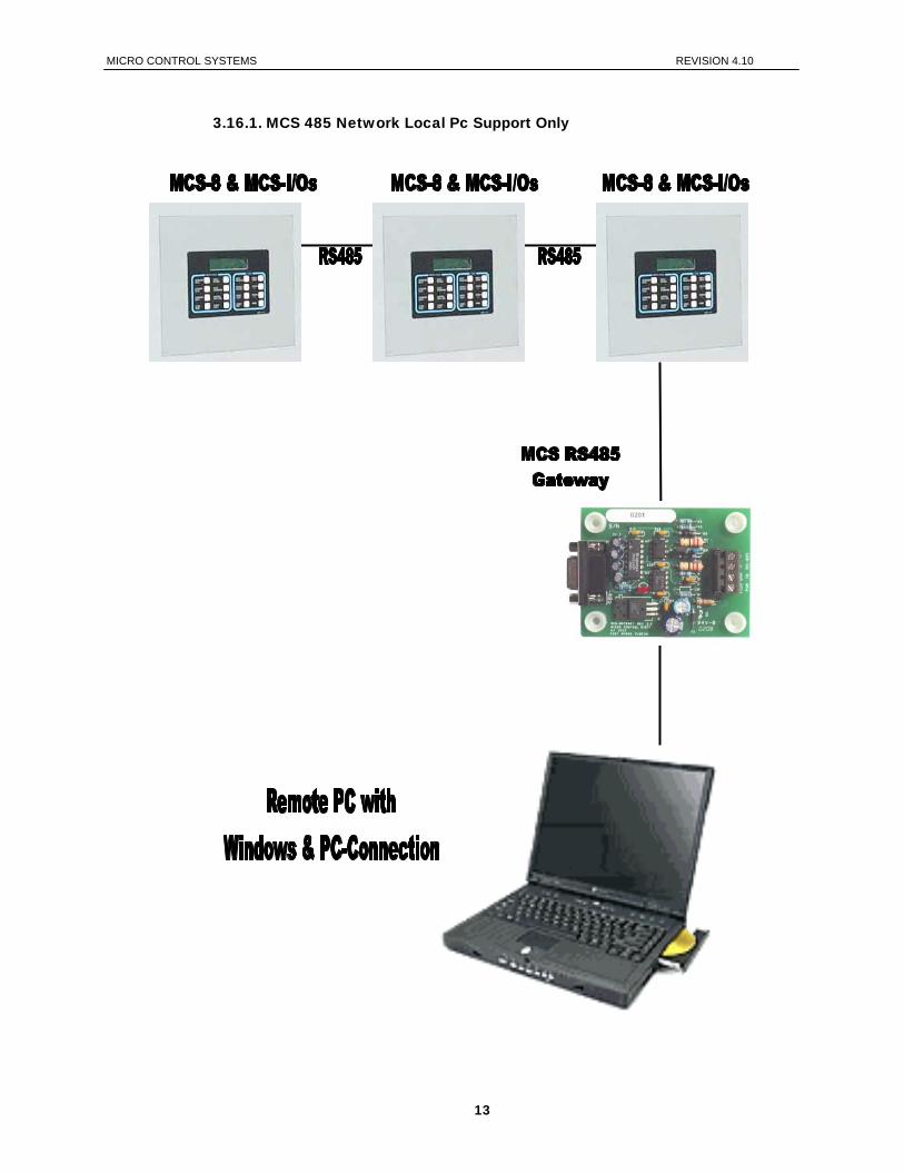
The MCS 485 Network can support up to 50 MCS-8 and its associated I/O’s. Access to this network can be local or remote via a 14.4K Baud modem. There will be no degradation in the performance of the network. The PC connected to the network must be running Windows 3.1 or higher with PC-Connect providing the actual interface program.
Each MCS-8 in the network must be assigned a unique address when the configuration file is build using the PC-Config program. This address will be the key in establishing communications with the appropriate MCS-8 system. This address can be changed from the LCD / keypad of a unit.
12
MICRO CONTROL SYSTEMS REVISION 4.10
3.16.1. MCS 485 Network Local Pc Support Only
13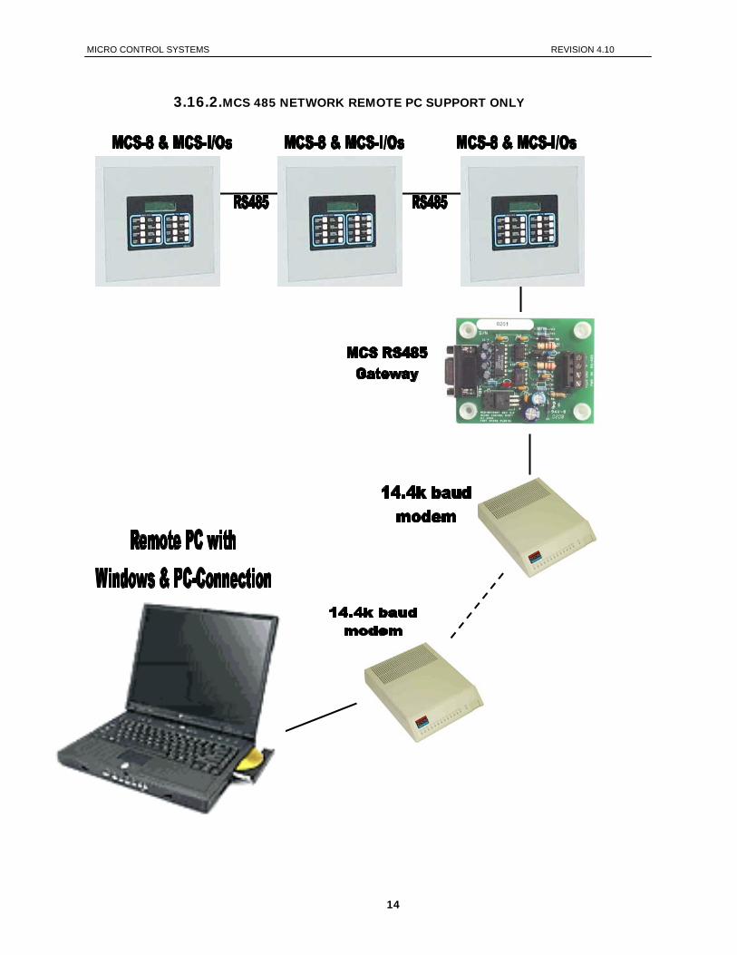
MICRO CONTROL SYSTEMS REVISION 4.10
3.16.2.MCS 485 NETWORK REMOTE PC SUPPORT ONLY
14

MICRO CONTROL SYSTEMS REVISION 4.10
4. Requirements for PC Software
To install and run the program we suggest the following system requirements: Front End System Requirements
Windows 95 Pentium 166 MHz 2 Gigabyte hard disk with at least 25 Megabytes free 3 ½ “ Floppy Disk Drive Super VGA display capable of displaying 256 colors 16 Megabytes of RAM or more is recommended 33.6k baud modem
Minimum System Required to Run Program
Windows 3.1 486 66 MHz 500 Megabyte Hard Drive 3½” Floppy Drive VGA Display 8 Megabytes RAM 14.4k baud modem
15
MICRO CONTROL SYSTEMS REVISION 4.10
5. MCS-8 Control Zone Control Method Option This control strategy is based upon developing a control zone and then to step the compressor(s) through their stages to maintain the control sensor reading within this zone. To accomplish this the system will constantly monitor the control value, its rate of change and position in relationship to the control zone.
The actual strategy of a fixed step system, reciprocating compressor, and a variable (slide) step system, screw compressor or a reciprocating compressor with an inverter, is slightly different. The variable step system allows for infinite variations of capacity while the fixed step system does not. This option is active in all software and is specified in the PC-Config program.
5.1. Common Definitions
5.1.1. Target
The control target is specified in setpoint 1. This will be the base of developing the control zone.
5.1.2. Control Zone
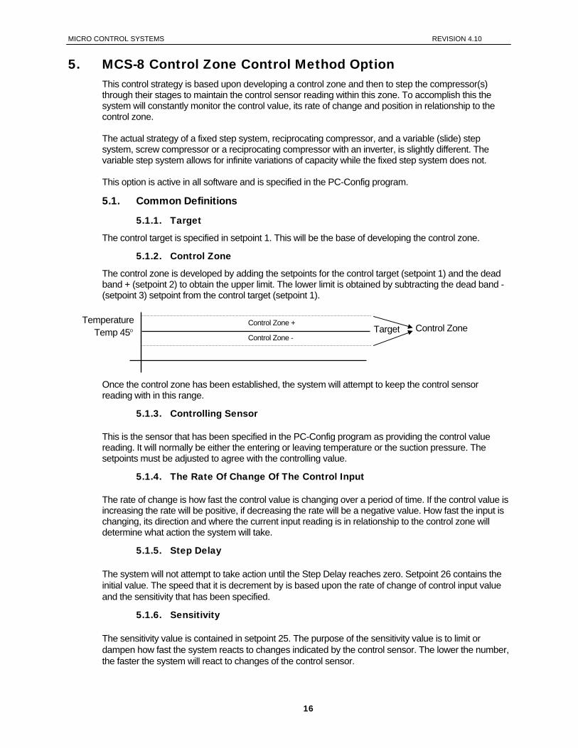
The control zone is developed by adding the setpoints for the control target (setpoint 1) and the dead band + (setpoint 2) to obtain the upper limit. The lower limit is obtained by subtracting the dead band - (setpoint 3) setpoint from the control target (setpoint 1).
Once the control zone has been established, the system will attempt to keep the control sensor reading with in this range.
Temp 45° Temperature
TargetControl Zone -
Control Zone + Control Zone
5.1.3. Controlling Sensor
This is the sensor that has been specified in the PC-Config program as providing the control value reading. It will normally be either the entering or leaving temperature or the suction pressure. The setpoints must be adjusted to agree with the controlling value.
5.1.4. The Rate Of Change Of The Control Input
The rate of change is how fast the control value is changing over a period of time. If the control value is increasing the rate will be positive, if decreasing the rate will be a negative value. How fast the input is changing, its direction and where the current input reading is in relationship to the control zone will determine what action the system will take.
5.1.5. Step Delay
The system will not attempt to take action until the Step Delay reaches zero. Setpoint 26 contains the initial value. The speed that it is decrement by is based upon the rate of change of control input value and the sensitivity that has been specified.
5.1.6. Sensitivity
The sensitivity value is contained in setpoint 25. The purpose of the sensitivity value is to limit or dampen how fast the system reacts to changes indicated by the control sensor. The lower the number, the faster the system will react to changes of the control sensor.
16
MICRO CONTROL SYSTEMS REVISION 4.10
6. MCS-8 Voltage SI Control Method This control strategy is based upon developing a series of cut in (turn on) and cut out (turn off) values for each capacity stage (step) in the system. When a cut in value has been reached or exceeded and the delay time between stages (steps) has been satisfied, the micro will turn on the next stage (step). Conversely, when a cut out value has been reached and the delay time between stages (steps) has been satisfied, the micro will turn off the last stage (step) that was turned on. This option is specified in the PC-Config program and is only supported in the CHL I08, CHL R08 (fixed step), CHL M08 (Mitsubishi fixed step screw) and CHL S08 (semi-hermetic screw) software versions.
6.1. Common Definitions
6.1.1. Targets, Stage Cut In Values
The control targets, stage cut in values, for up to 16 steps of capacity are specified in setpoints 3 through 18.
6.1.2. Stage Cut Out Values
The stage cut out values for each step of capacity is calculated by subtracting setpoint 2 from the individual step cut in value.
6.1.3. Step Delay
The step delay is contained in setpoint 1. This is the minimum time between changes in capacity.
6.1.4. Controlling Sensor
This is the sensor that has been specified in the PC-Config program as providing the control value. It will normally be either a voltage that is being provided by an external system, entering or leaving temperature or the suction pressure. The setpoints must be adjusted to agree with the controlling value.
17

MICRO CONTROL SYSTEMS REVISION 4.10
7. Standard Variable Step Control Method This option is specified in the PC-Config program and is only supported in the CHL C08, CHL H08, CHL I08, CHL R08 (fixed step), CHL M08 (Mitsubishi fixed step screw), CHL O08, CHL S08 (semi-hermetic screw) and CHL T08 software versions.
The system will attempt to keep the control value with in the control zone that has been developed by calculating the required system capacity. The system capacity will be based upon the number of circuits (compressors) that are wanted on. When the first or an addition compressor is turned on, the system capacity will be set to the minimum value as specified in setpoint #31, MIN SLIDE %. The system will adjust the required capacity between the minimum and the maximum value an as specified in setpoint #30, MAX SLIDE %. All compressors that are on will be adjusted together to meet the system capacity. When the maximum capacity value has been reached, an additional compressor, if available, will be wanted on. The number of compressors wanted on will be increased by one and the system capacity will be set to the minimum value and the sequence will began again. Once all available compressors are on, their maximum will be 100% regardless of the value in setpoint #30, MAX SLIDE %. When the minimum capacity value has been reached, a compressor will be turned off. The number of compressors wanted on will be decreased by one and the system capacity will be set to the maximum value and the sequence will began again. The compressor slide control is based upon the amps drawn of that compressor. For example if setpoint #31, MIN SLIDE %, is set to 30%, that is 30% of the full load amp for that compressor. An acceptable zone for the amp draw is developed based upon the desired capacity and setpoints #35 and #36. If the amp drawn is greater than the indicated capacity needed then the compressor is unloaded. Conversely if it is less, then it is loaded. The compressors that are on are either loaded, their load solenoids are pulsed; unloaded, their unload solenoids are pulsed or are in a hold state, no action is required. The state of each circuit (compressor) reflects this action. Setpoints for controlling Variable Step Compressors
30 MAX SLIDE % Indicates the maximum slide or speed allowed. Usually set to 100%. 31 MIN SLIDE % Indicates the minimum slide or speed allowed. Usually 50%. This is where the
slide valve or the inverter will be set when the compressor is turned on. 32 MAX ADJUST % Indicates the maximum percentage change that can be made to the slide valve
or the inverter when more cooling capability is needed. 33 MIN ADJUST % Indicates the minimum percentage change that can be made to the slide valve or
the inverter when less cooling capability is needed. 34 SLIDE SENSITY This allows control of the adjustment made to slide wanted percentage. The
adjustment is relative to the difference between current leaving liquid temperature and target. The larger the value the larger the adjustment.
35 AMP DB HI This setpoint is only used in the screw compressors. This value is the upper dead band limit to stop pulsing the slide valve. If the actual amps are within the dead band, the slide valve will not be moved.
36 AMP DB LO This value is the lower dead band limit to stop pulsing the slide valve. If the actual amps are within the dead band, the slide valve will not be moved.
37 LOAD PULSE Length of time to turn on the slide valve load solenoid. Time is expressed in 1/10 of a second.
18
MICRO CONTROL SYSTEMS REVISION 4.10
38 UNLOAD PULSE Length of time to turn on the slide valve unloader solenoid. Time is expressed in 1/10 of a second.
39 LUBE OIL TMP Used only with screw compressors with oil, the oil must reach this temperature before the system will move out of the LUBE state.
40 LUBE OIL PSI Used only with screw compressors with oil, the oil must reach this pressure before the system will move out of the LUBE state.
41 LUBE DELAY Used only with screw compressors with oil, this is the maximum time that a compressor can be in the LUBE state. When this time is exceeded, an alarm is generated and the circuit is placed in a lockout state. Both the oil temperature and pressure must be satisfied before the LUBE state will be exited.
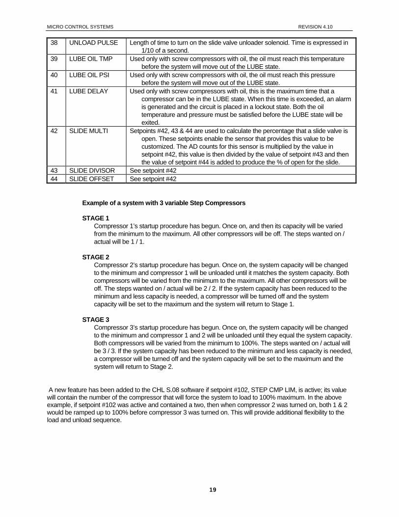
42 SLIDE MULTI Setpoints #42, 43 & 44 are used to calculate the percentage that a slide valve is open. These setpoints enable the sensor that provides this value to be customized. The AD counts for this sensor is multiplied by the value in setpoint #42, this value is then divided by the value of setpoint #43 and then the value of setpoint #44 is added to produce the % of open for the slide.
43 SLIDE DIVISOR See setpoint #42 44 SLIDE OFFSET See setpoint #42
Example of a system with 3 variable Step Compressors STAGE 1
Compressor 1’s startup procedure has begun. Once on, and then its capacity will be varied from the minimum to the maximum. All other compressors will be off. The steps wanted on / actual will be 1 / 1.
STAGE 2 Compressor 2’s startup procedure has begun. Once on, the system capacity will be changed to the minimum and compressor 1 will be unloaded until it matches the system capacity. Both compressors will be varied from the minimum to the maximum. All other compressors will be off. The steps wanted on / actual will be 2 / 2. If the system capacity has been reduced to the minimum and less capacity is needed, a compressor will be turned off and the system capacity will be set to the maximum and the system will return to Stage 1.
STAGE 3 Compressor 3’s startup procedure has begun. Once on, the system capacity will be changed to the minimum and compressor 1 and 2 will be unloaded until they equal the system capacity. Both compressors will be varied from the minimum to 100%. The steps wanted on / actual will be 3 / 3. If the system capacity has been reduced to the minimum and less capacity is needed, a compressor will be turned off and the system capacity will be set to the maximum and the system will return to Stage 2.
A new feature has been added to the CHL S.08 software if setpoint #102, STEP CMP LIM, is active; its value will contain the number of the compressor that will force the system to load to 100% maximum. In the above example, if setpoint #102 was active and contained a two, then when compressor 2 was turned on, both 1 & 2 would be ramped up to 100% before compressor 3 was turned on. This will provide additional flexibility to the load and unload sequence.
19
MICRO CONTROL SYSTEMS REVISION 4.10
8. MCS-8 Control States We should consider the MCS-8 controller as a state computer, that is, decisions are made based upon setpoints, timers and sensor inputs, the controller moves from one state to another. The controller will change states to ensure the proper functioning of the chiller package. As we review the various states, we must remember that a chiller package consists of a number of different parts or functions: the compressors and their related items such as unloaders hot gas bypasses, etc.; evaporator; and condensing functions. To control these functions the states will be divided into three sections: Capacity Control States Circuit Control States Condenser Control States
Both the CAPACITY CONTROL STATES and CIRCUIT CONTROL STATES are displayed on the 2x16 LCD. Press the SERVICE DIAGNOSTICS key until the option is the CONTROL STATUS, then press the ENTER key. The INCREASE and DECREASE keys can be used to scroll through the various state screens. Or it can be accessed via the PC-Connect program under status screen by clicking on the CONTROL STATUS button.
8.1. Control Status Display (from the MCS-8 keypad)
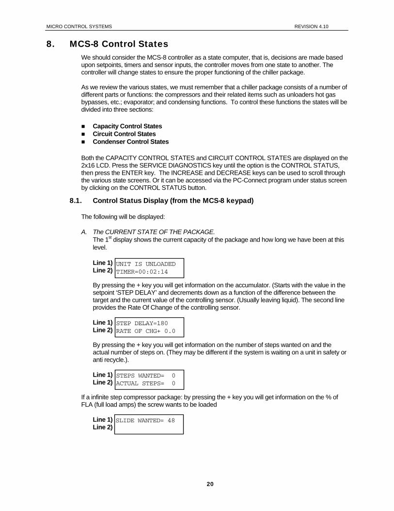
The following will be displayed: A. The CURRENT STATE OF THE PACKAGE.
The 1st display shows the current capacity of the package and how long we have been at this level. Line 1) Line 2)
By pressing the + key you will get information on the accumulator. (Starts with the value in the setpoint ‘STEP DELAY’ and decrements down as a function of the difference between the target and the current value of the controlling sensor. (Usually leaving liquid). The second line provides the Rate Of Change of the controlling sensor.
Line 1) Line 2)
By pressing the + key you will get information on the number of steps wanted on and the actual number of steps on. (They may be different if the system is waiting on a unit in safety or anti recycle.).
Line 1) Line 2)
UNIT IS UNLOADED TIMER=00:02:14
STEP DELAY=180 RATE OF CHG+ 0.0
STEPS WANTED= 0 ACTUAL STEPS= 0
If a infinite step compressor package: by pressing the + key you will get information on the % of FLA (full load amps) the screw wants to be loaded
Line 1) Line 2)
SLIDE WANTED= 48
20
MICRO CONTROL SYSTEMS REVISION 4.10
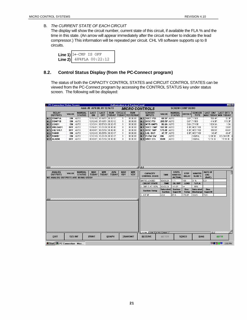
B. The CURRENT STATE OF EACH CIRCUIT The display will show the circuit number, current state of this circuit, if available the FLA % and the time in this state. (An arrow will appear immediately after the circuit number to indicate the lead compressor.) This information will be repeated per circuit. CHL V8 software supports up to 8 circuits.
Line 1) Line 2)
1←CMP IS OFF 48%FLA 00:22:12
8.2. Control Status Display (from the PC-Connect program)
The status of both the CAPACITY CONTROL STATES and CIRCUIT CONTROL STATES can be viewed from the PC-Connect program by accessing the CONTROL STATUS key under status screen. The following will be displayed:
21
MICRO CONTROL SYSTEMS REVISION 4.10
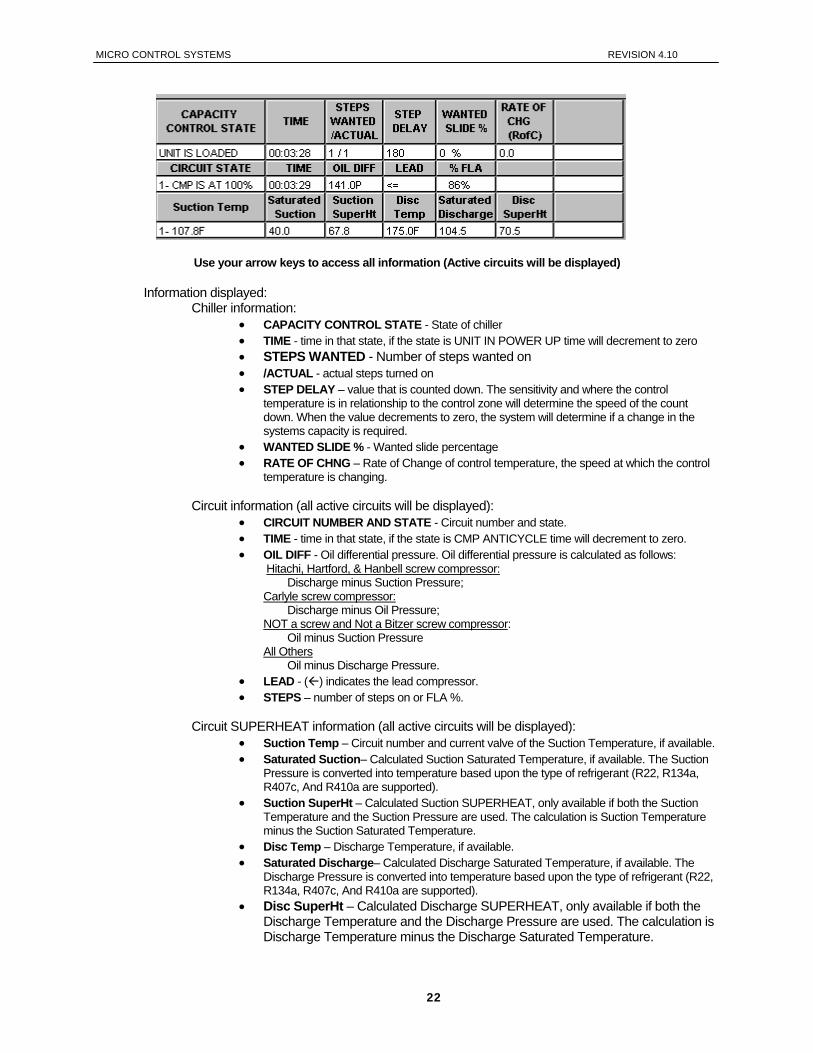
Use your arrow keys to access all information (Active circuits will be displayed)
Information displayed:
Chiller information: • CAPACITY CONTROL STATE - State of chiller • TIME - time in that state, if the state is UNIT IN POWER UP time will decrement to zero • STEPS WANTED - Number of steps wanted on • /ACTUAL - actual steps turned on • STEP DELAY – value that is counted down. The sensitivity and where the control
temperature is in relationship to the control zone will determine the speed of the count down. When the value decrements to zero, the system will determine if a change in the systems capacity is required.
• WANTED SLIDE % - Wanted slide percentage • RATE OF CHNG – Rate of Change of control temperature, the speed at which the control
temperature is changing.
Circuit information (all active circuits will be displayed): • CIRCUIT NUMBER AND STATE - Circuit number and state. • TIME - time in that state, if the state is CMP ANTICYCLE time will decrement to zero. • OIL DIFF - Oil differential pressure. Oil differential pressure is calculated as follows:
Hitachi, Hartford, & Hanbell screw compressor: Discharge minus Suction Pressure;
Carlyle screw compressor: Discharge minus Oil Pressure;
NOT a screw and Not a Bitzer screw compressor: Oil minus Suction Pressure
All Others Oil minus Discharge Pressure.
• LEAD - ( ) indicates the lead compressor. • STEPS – number of steps on or FLA %.
Circuit SUPERHEAT information (all active circuits will be displayed): • Suction Temp – Circuit number and current valve of the Suction Temperature, if available. • Saturated Suction– Calculated Suction Saturated Temperature, if available. The Suction
Pressure is converted into temperature based upon the type of refrigerant (R22, R134a, R407c, And R410a are supported).
• Suction SuperHt – Calculated Suction SUPERHEAT, only available if both the Suction Temperature and the Suction Pressure are used. The calculation is Suction Temperature minus the Suction Saturated Temperature.
• Disc Temp – Discharge Temperature, if available. • Saturated Discharge– Calculated Discharge Saturated Temperature, if available. The
Discharge Pressure is converted into temperature based upon the type of refrigerant (R22, R134a, R407c, And R410a are supported).
• Disc SuperHt – Calculated Discharge SUPERHEAT, only available if both the Discharge Temperature and the Discharge Pressure are used. The calculation is Discharge Temperature minus the Discharge Saturated Temperature.
22
MICRO CONTROL SYSTEMS REVISION 4.10
9. Capacity Control States Capacity Control States are active for all five releases of software.
UNIT IN POWER UP
This state is entered when the MCS-8 is powered up or the system has been reset. The system will remain in this state for the time specified in setpoint POWER DELAY, setpoint 23, or if not active for 60 seconds. In this state all points (RO’s) are turned off. This is a time delay to insure the micro has stable power before turning any points on.
UNIT IN LOCKOUT
This state is entered whenever a critical situation is encountered that could cause harm to the chiller package. Items such as freeze protect, no flow and emergency stop will force the system into this state. Lockouts can be reset without authorization from the keypad or PC-Connect program; however if the lockout condition has not been corrected, the system will again be forced into the LOCKOUT state. In this state, all RO’s except ALARM RO and the oil heater RO for screws with an oil pump are turned OFF & placed in the ‘LOCKOUT’ state.
NO RUN- I/O LOST
This state will be entered whenever the MCS-8 loses communications with any of the I/O boards that are connected via the MCS I/O network. When this state is entered the system will generate an MCS I/O off line alarm, which identifies which I/O is off-line and a lost I/O shutdown alarm which locks out the unit. The lockout-reset key must be depressed to reset the system, after the lost I/O has been corrected. In this state, all RO’s except ALARM RO are turned OFF.
RUN/STOP SW OFF
This state is entered when the run stop switch is off, in the stop position. When the chiller is in this state, the individual circuit states if active are moved to the CMP IS OFF state through the normal states. One capacity STEP will be moved per second.
SCHEDULED OFF
This state is entered when the schedule is calling for the package to be off. When the chiller is in this state, the individual circuit states if active are moved to the CMP IS OFF state through the normal states. One capacity STEP will be moved per second.
OFF- NO EVAP FLOW
This state is entered when the evaporator flow switch is off. When the chiller is in this state, the individual circuit states if active are moved to the CMP IS OFF state through the normal states. One capacity STEP will be moved per second.
AMBIENT OFF
This state is entered when the ambient temperature falls below the LOW AMB OFF setpoint #24 or is above the HIGH AMB OFF setpoint #26. System will remain in this state until the ambient temperature if low rises 5.0F or 2.5C degrees above the LOW AMB OFF setpoint value or if high drops 5.0F or 2.5C degrees below the HIGH AMB OFF setpoint value. When the chiller is in this state, the individual circuit states if active are moved to the CMP IS OFF state through the normal staging function. One capacity STEP will be moved per second.
23
MICRO CONTROL SYSTEMS REVISION 4.10
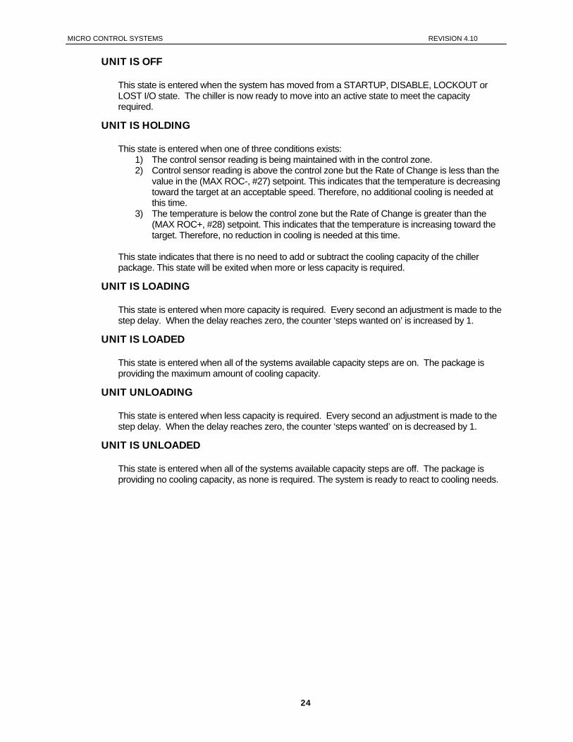
UNIT IS OFF
This state is entered when the system has moved from a STARTUP, DISABLE, LOCKOUT or LOST I/O state. The chiller is now ready to move into an active state to meet the capacity required.
UNIT IS HOLDING
This state is entered when one of three conditions exists: 1) The control sensor reading is being maintained with in the control zone. 2) Control sensor reading is above the control zone but the Rate of Change is less than the
value in the (MAX ROC-, #27) setpoint. This indicates that the temperature is decreasing toward the target at an acceptable speed. Therefore, no additional cooling is needed at this time.
3) The temperature is below the control zone but the Rate of Change is greater than the (MAX ROC+, #28) setpoint. This indicates that the temperature is increasing toward the target. Therefore, no reduction in cooling is needed at this time.
This state indicates that there is no need to add or subtract the cooling capacity of the chiller package. This state will be exited when more or less capacity is required.
UNIT IS LOADING
This state is entered when more capacity is required. Every second an adjustment is made to the step delay. When the delay reaches zero, the counter ‘steps wanted on’ is increased by 1.
UNIT IS LOADED
This state is entered when all of the systems available capacity steps are on. The package is providing the maximum amount of cooling capacity.
UNIT UNLOADING
This state is entered when less capacity is required. Every second an adjustment is made to the step delay. When the delay reaches zero, the counter ‘steps wanted’ on is decreased by 1.
UNIT IS UNLOADED
This state is entered when all of the systems available capacity steps are off. The package is providing no cooling capacity, as none is required. The system is ready to react to cooling needs.
24
MICRO CONTROL SYSTEMS REVISION 4.10
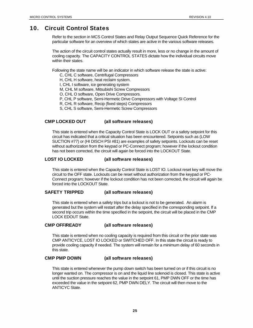
10. Circuit Control States Refer to the section in MCS Control States and Relay Output Sequence Quick Reference for the particular software for an overview of which states are active in the various software releases. The action of the circuit control states actually result in more, less or no change in the amount of cooling capacity. The CAPACITY CONTROL STATES dictate how the individual circuits move within their states. Following the state name will be an indicator in which software release the state is active:
C, CHL C software, Centrifugal Compressors H, CHL H software, heat reclaim system. I, CHL I software, ice generating system M, CHL M software, Mitsubishi Screw Compressors O, CHL O software, Open Drive Compressors. P, CHL P software, Semi-Hermetic Drive Compressors with Voltage SI Control R, CHL R software, Recip (fixed steps) Compressors S, CHL S software, Semi-Hermetic Screw Compressors
CMP LOCKED OUT (all software releases)
This state is entered when the Capacity Control State is LOCK OUT or a safety setpoint for this circuit has indicated that a critical situation has been encountered. Setpoints such as (LOW SUCTION #77) or (HI DISCH PSI #81) are examples of safety setpoints. Lockouts can be reset without authorization from the keypad or PC-Connect program; however if the lockout condition has not been corrected, the circuit will again be forced into the LOCKOUT State.
LOST IO LOCKED (all software releases)
This state is entered when the Capacity Control State is LOST IO. Lockout reset key will move the circuit to the OFF state. Lockouts can be reset without authorization from the keypad or PC-Connect program; however if the lockout condition has not been corrected, the circuit will again be forced into the LOCKOUT State.
SAFETY TRIPPED (all software releases)
This state is entered when a safety trips but a lockout is not to be generated. An alarm is generated but the system will restart after the delay specified in the corresponding setpoint. If a second trip occurs within the time specified in the setpoint, the circuit will be placed in the CMP LOCK EDOUT State.
CMP OFF/READY (all software releases)
This state is entered when no cooling capacity is required from this circuit or the prior state was CMP ANTICYCE, LOST IO LOCKED or SWITCHED OFF. In this state the circuit is ready to provide cooling capacity if needed. The system will remain for a minimum delay of 60 seconds in this state.
CMP PMP DOWN (all software releases)
This state is entered whenever the pump down switch has been turned on or if this circuit is no longer wanted on. The compressor is on and the liquid line solenoid is closed. This state is active until the suction pressure reaches the value in the setpoint 61, PMP DWN OFF or the time has exceeded the value in the setpoint 62, PMP DWN DELY. The circuit will then move to the ANTICYC State.
25
MICRO CONTROL SYSTEMS REVISION 4.10
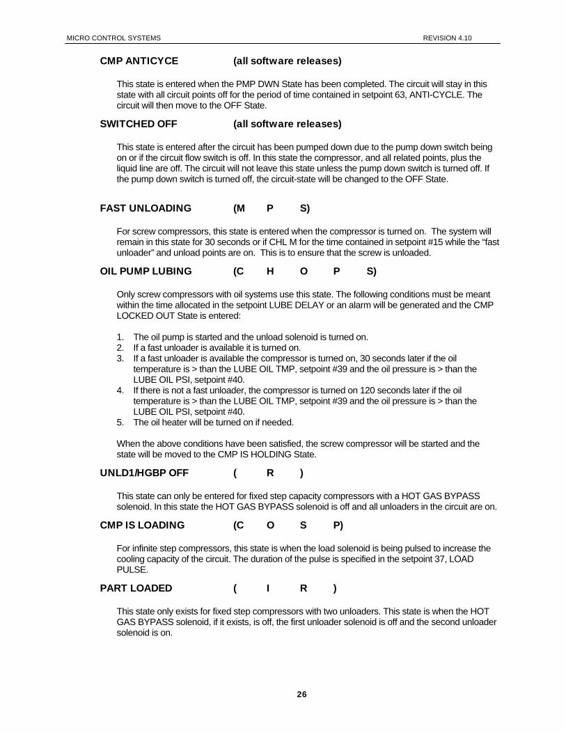
CMP ANTICYCE (all software releases)
This state is entered when the PMP DWN State has been completed. The circuit will stay in this state with all circuit points off for the period of time contained in setpoint 63, ANTI-CYCLE. The circuit will then move to the OFF State.
SWITCHED OFF (all software releases)
This state is entered after the circuit has been pumped down due to the pump down switch being on or if the circuit flow switch is off. In this state the compressor, and all related points, plus the liquid line are off. The circuit will not leave this state unless the pump down switch is turned off. If the pump down switch is turned off, the circuit-state will be changed to the OFF State.
FAST UNLOADING (M P S)
For screw compressors, this state is entered when the compressor is turned on. The system will remain in this state for 30 seconds or if CHL M for the time contained in setpoint #15 while the “fast unloader” and unload points are on. This is to ensure that the screw is unloaded.
OIL PUMP LUBING (C H O P S)
Only screw compressors with oil systems use this state. The following conditions must be meant within the time allocated in the setpoint LUBE DELAY or an alarm will be generated and the CMP LOCKED OUT State is entered: 1. The oil pump is started and the unload solenoid is turned on. 2. If a fast unloader is available it is turned on. 3. If a fast unloader is available the compressor is turned on, 30 seconds later if the oil
temperature is > than the LUBE OIL TMP, setpoint #39 and the oil pressure is > than the LUBE OIL PSI, setpoint #40.
4. If there is not a fast unloader, the compressor is turned on 120 seconds later if the oil temperature is > than the LUBE OIL TMP, setpoint #39 and the oil pressure is > than the LUBE OIL PSI, setpoint #40.
5. The oil heater will be turned on if needed. When the above conditions have been satisfied, the screw compressor will be started and the state will be moved to the CMP IS HOLDING State.
UNLD1/HGBP OFF ( R )
This state can only be entered for fixed step capacity compressors with a HOT GAS BYPASS solenoid. In this state the HOT GAS BYPASS solenoid is off and all unloaders in the circuit are on.
CMP IS LOADING (C O S P)
For infinite step compressors, this state is when the load solenoid is being pulsed to increase the cooling capacity of the circuit. The duration of the pulse is specified in the setpoint 37, LOAD PULSE.
PART LOADED ( I R )
This state only exists for fixed step compressors with two unloaders. This state is when the HOT GAS BYPASS solenoid, if it exists, is off, the first unloader solenoid is off and the second unloader solenoid is on.
26
MICRO CONTROL SYSTEMS REVISION 4.10
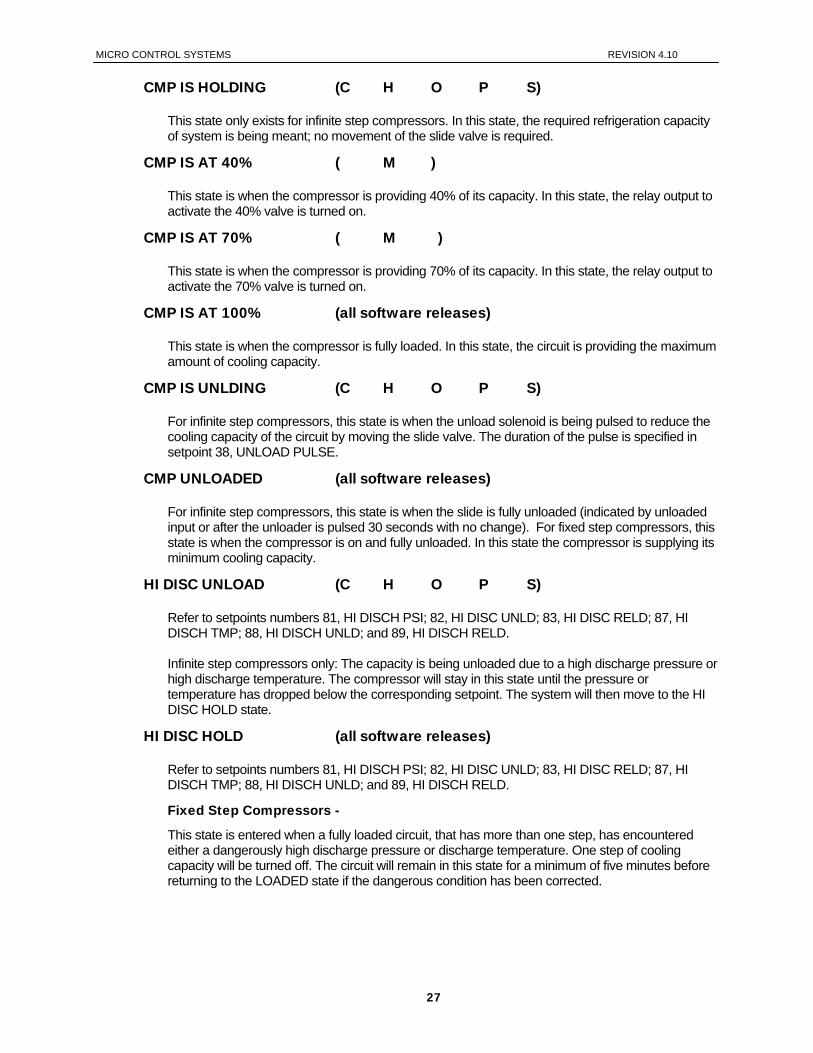
CMP IS HOLDING (C H O P S)
This state only exists for infinite step compressors. In this state, the required refrigeration capacity of system is being meant; no movement of the slide valve is required.
CMP IS AT 40% ( M )
This state is when the compressor is providing 40% of its capacity. In this state, the relay output to activate the 40% valve is turned on.
CMP IS AT 70% ( M )
This state is when the compressor is providing 70% of its capacity. In this state, the relay output to activate the 70% valve is turned on.
CMP IS AT 100% (all software releases)
This state is when the compressor is fully loaded. In this state, the circuit is providing the maximum amount of cooling capacity.
CMP IS UNLDING (C H O P S)
For infinite step compressors, this state is when the unload solenoid is being pulsed to reduce the cooling capacity of the circuit by moving the slide valve. The duration of the pulse is specified in setpoint 38, UNLOAD PULSE.
CMP UNLOADED (all software releases)
For infinite step compressors, this state is when the slide is fully unloaded (indicated by unloaded input or after the unloader is pulsed 30 seconds with no change). For fixed step compressors, this state is when the compressor is on and fully unloaded. In this state the compressor is supplying its minimum cooling capacity.
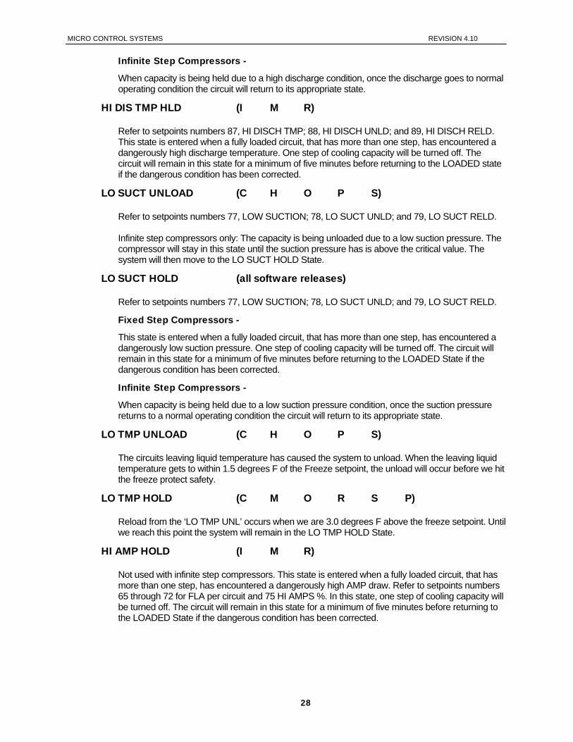
HI DISC UNLOAD (C H O P S)
Refer to setpoints numbers 81, HI DISCH PSI; 82, HI DISC UNLD; 83, HI DISC RELD; 87, HI DISCH TMP; 88, HI DISCH UNLD; and 89, HI DISCH RELD. Infinite step compressors only: The capacity is being unloaded due to a high discharge pressure or high discharge temperature. The compressor will stay in this state until the pressure or temperature has dropped below the corresponding setpoint. The system will then move to the HI DISC HOLD state.
HI DISC HOLD (all software releases)
Refer to setpoints numbers 81, HI DISCH PSI; 82, HI DISC UNLD; 83, HI DISC RELD; 87, HI DISCH TMP; 88, HI DISCH UNLD; and 89, HI DISCH RELD.
Fixed Step Compressors -
This state is entered when a fully loaded circuit, that has more than one step, has encountered either a dangerously high discharge pressure or discharge temperature. One step of cooling capacity will be turned off. The circuit will remain in this state for a minimum of five minutes before returning to the LOADED state if the dangerous condition has been corrected.
27
MICRO CONTROL SYSTEMS REVISION 4.10
Infinite Step Compressors -
When capacity is being held due to a high discharge condition, once the discharge goes to normal operating condition the circuit will return to its appropriate state.
HI DIS TMP HLD (I M R)
Refer to setpoints numbers 87, HI DISCH TMP; 88, HI DISCH UNLD; and 89, HI DISCH RELD. This state is entered when a fully loaded circuit, that has more than one step, has encountered a dangerously high discharge temperature. One step of cooling capacity will be turned off. The circuit will remain in this state for a minimum of five minutes before returning to the LOADED state if the dangerous condition has been corrected.
LO SUCT UNLOAD (C H O P S)
Refer to setpoints numbers 77, LOW SUCTION; 78, LO SUCT UNLD; and 79, LO SUCT RELD. Infinite step compressors only: The capacity is being unloaded due to a low suction pressure. The compressor will stay in this state until the suction pressure has is above the critical value. The system will then move to the LO SUCT HOLD State.
LO SUCT HOLD (all software releases)
Refer to setpoints numbers 77, LOW SUCTION; 78, LO SUCT UNLD; and 79, LO SUCT RELD.
Fixed Step Compressors -
This state is entered when a fully loaded circuit, that has more than one step, has encountered a dangerously low suction pressure. One step of cooling capacity will be turned off. The circuit will remain in this state for a minimum of five minutes before returning to the LOADED State if the dangerous condition has been corrected.
Infinite Step Compressors -
When capacity is being held due to a low suction pressure condition, once the suction pressure returns to a normal operating condition the circuit will return to its appropriate state.
LO TMP UNLOAD (C H O P S)
The circuits leaving liquid temperature has caused the system to unload. When the leaving liquid temperature gets to within 1.5 degrees F of the Freeze setpoint, the unload will occur before we hit the freeze protect safety.
LO TMP HOLD (C M O R S P)
Reload from the ‘LO TMP UNL’ occurs when we are 3.0 degrees F above the freeze setpoint. Until we reach this point the system will remain in the LO TMP HOLD State.
HI AMP HOLD (I M R)
Not used with infinite step compressors. This state is entered when a fully loaded circuit, that has more than one step, has encountered a dangerously high AMP draw. Refer to setpoints numbers 65 through 72 for FLA per circuit and 75 HI AMPS %. In this state, one step of cooling capacity will be turned off. The circuit will remain in this state for a minimum of five minutes before returning to the LOADED State if the dangerous condition has been corrected.
28
MICRO CONTROL SYSTEMS REVISION 4.10
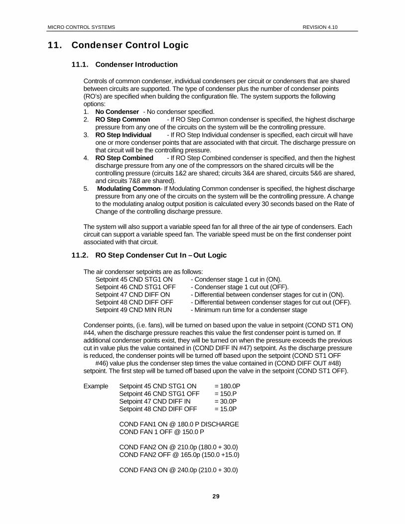
11. Condenser Control Logic
11.1. Condenser Introduction
Controls of common condenser, individual condensers per circuit or condensers that are shared between circuits are supported. The type of condenser plus the number of condenser points (RO’s) are specified when building the configuration file. The system supports the following options: 1. No Condenser - No condenser specified. 2. RO Step Common - If RO Step Common condenser is specified, the highest discharge
pressure from any one of the circuits on the system will be the controlling pressure. 3. RO Step Individual - If RO Step Individual condenser is specified, each circuit will have
one or more condenser points that are associated with that circuit. The discharge pressure on that circuit will be the controlling pressure.
4. RO Step Combined - If RO Step Combined condenser is specified, and then the highest discharge pressure from any one of the compressors on the shared circuits will be the controlling pressure (circuits 1&2 are shared; circuits 3&4 are shared, circuits 5&6 are shared, and circuits 7&8 are shared).
5. Modulating Common- If Modulating Common condenser is specified, the highest discharge pressure from any one of the circuits on the system will be the controlling pressure. A change to the modulating analog output position is calculated every 30 seconds based on the Rate of Change of the controlling discharge pressure.
The system will also support a variable speed fan for all three of the air type of condensers. Each circuit can support a variable speed fan. The variable speed must be on the first condenser point associated with that circuit.
11.2. RO Step Condenser Cut In – Out Logic
The air condenser setpoints are as follows: Setpoint 45 CND STG1 ON - Condenser stage 1 cut in (ON). Setpoint 46 CND STG1 OFF - Condenser stage 1 cut out (OFF). Setpoint 47 CND DIFF ON - Differential between condenser stages for cut in (ON). Setpoint 48 CND DIFF OFF - Differential between condenser stages for cut out (OFF). Setpoint 49 CND MIN RUN - Minimum run time for a condenser stage
Condenser points, (i.e. fans), will be turned on based upon the value in setpoint (COND ST1 ON) #44, when the discharge pressure reaches this value the first condenser point is turned on. If additional condenser points exist, they will be turned on when the pressure exceeds the previous cut in value plus the value contained in (COND DIFF IN #47) setpoint. As the discharge pressure is reduced, the condenser points will be turned off based upon the setpoint (COND ST1 OFF #46) value plus the condenser step times the value contained in (COND DIFF OUT #48) setpoint. The first step will be turned off based upon the valve in the setpoint (COND ST1 OFF). Example Setpoint 45 CND STG1 ON = 180.0P Setpoint 46 CND STG1 OFF = 150.P Setpoint 47 CND DIFF IN = 30.0P Setpoint 48 CND DIFF OFF = 15.0P COND FAN1 ON @ 180.0 P DISCHARGE COND FAN 1 OFF @ 150.0 P COND FAN2 ON @ 210.0p (180.0 + 30.0) COND FAN2 OFF @ 165.0p (150.0 +15.0) COND FAN3 ON @ 240.0p (210.0 + 30.0)
29
MICRO CONTROL SYSTEMS REVISION 4.10
COND FAN3 OFF @ 180.0p (165.0 + 15.0), etc.
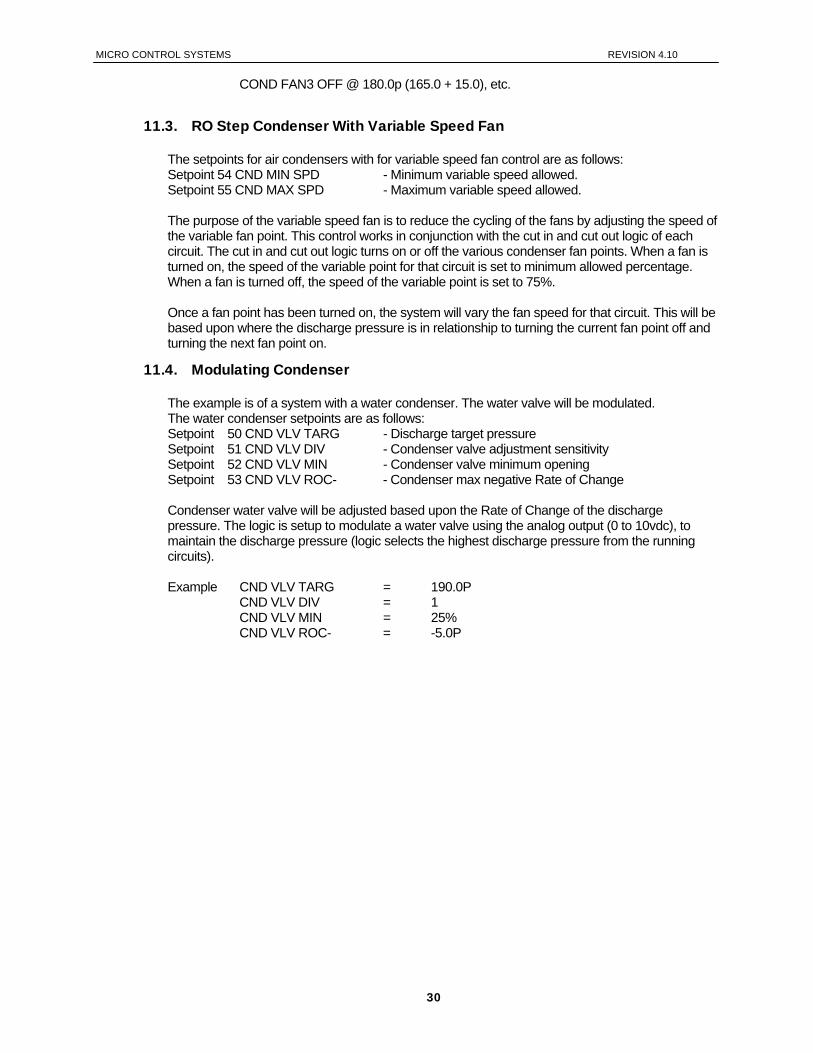
11.3. RO Step Condenser With Variable Speed Fan
The setpoints for air condensers with for variable speed fan control are as follows: Setpoint 54 CND MIN SPD - Minimum variable speed allowed. Setpoint 55 CND MAX SPD - Maximum variable speed allowed. The purpose of the variable speed fan is to reduce the cycling of the fans by adjusting the speed of the variable fan point. This control works in conjunction with the cut in and cut out logic of each circuit. The cut in and cut out logic turns on or off the various condenser fan points. When a fan is turned on, the speed of the variable point for that circuit is set to minimum allowed percentage. When a fan is turned off, the speed of the variable point is set to 75%. Once a fan point has been turned on, the system will vary the fan speed for that circuit. This will be based upon where the discharge pressure is in relationship to turning the current fan point off and turning the next fan point on.
11.4. Modulating Condenser
The example is of a system with a water condenser. The water valve will be modulated. The water condenser setpoints are as follows: Setpoint 50 CND VLV TARG - Discharge target pressure Setpoint 51 CND VLV DIV - Condenser valve adjustment sensitivity Setpoint 52 CND VLV MIN - Condenser valve minimum opening Setpoint 53 CND VLV ROC- - Condenser max negative Rate of Change Condenser water valve will be adjusted based upon the Rate of Change of the discharge pressure. The logic is setup to modulate a water valve using the analog output (0 to 10vdc), to maintain the discharge pressure (logic selects the highest discharge pressure from the running circuits). Example CND VLV TARG = 190.0P CND VLV DIV = 1 CND VLV MIN = 25% CND VLV ROC- = -5.0P
30
MICRO CONTROL SYSTEMS REVISION 4.10
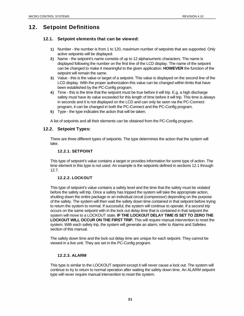
12. Setpoint Definitions
12.1. Setpoint elements that can be viewed:
1) Number - the number is from 1 to 120, maximum number of setpoints that are supported. Only active setpoints will be displayed.
2) Name - the setpoint’s name consists of up to 12 alphanumeric characters. The name is displayed following the number on the first line of the LCD display. The name of the setpoint can be changed to make it meaningful to the given application. HOWEVER the function of the setpoint will remain the same.
3) Value - this is the value or target of a setpoint. This value is displayed on the second line of the LCD display. With the proper authorization this value can be changed within limits that have been established by the PC-Config program.
4) Time - this is the time that the setpoint must be true before it will trip. E.g. a high discharge safety must have its value exceeded for this length of time before it will trip. This time is always in seconds and it is not displayed on the LCD and can only be seen via the PC-Connect program, it can be changed in both the PC-Connect and the PC-Config program.
5) Type - the type indicates the action that will be taken. A list of setpoints and all their elements can be obtained from the PC-Config program.
12.2. Setpoint Types:
There are three different types of setpoints. The type determines the action that the system will take.
12.2.1. SETPOINT
This type of setpoint’s value contains a target or provides information for some type of action. The time element in this type is not used. An example is the setpoints defined in sections 12.1 through 12.7.
12.2.2. LOCKOUT
This type of setpoint’s value contains a safety level and the time that the safety must be violated before the safety will trip. Once a safety has tripped the system will take the appropriate action, shutting down the entire package or an individual circuit (compressor) depending on the purpose of the safety. The system will then wait the safety down time contained in that setpoint before trying to return the system to normal. If successful, the system will continue to operate. If a second trip occurs on the same setpoint with in the lock out delay time that is contained in that setpoint the system will move to a LOCKOUT state. IF THE LOCKOUT DELAY TIME IS SET TO ZERO THE LOCKOUT WILL OCCUR ON THE FIRST TRIP. This will require manual intervention to reset the system. With each safety trip, the system will generate an alarm; refer to Alarms and Safeties section of this manual. The safety down time and the lock out delay time are unique for each setpoint. They cannot be viewed in a live unit. They are set in the PC-Config program.
12.2.3. ALARM
This type is similar to the LOCKOUT setpoint except it will never cause a lock out. The system will continue to try to return to normal operation after waiting the safety down time. An ALARM setpoint type will never require manual intervention to reset the system.
31

MICRO CONTROL SYSTEMS REVISION 4.10
13. Setpoints for Chiller V8 Algorithm
13.1. Voltage SI Control Method setpoints #1-18
This method of control is supported in CHL I, CHL M, CHL P & CHL R software only, these also support the Control Zone Method. Select option in PC-Config program.
# NAME DESCRIPTION 1 STAGE DELAY Delay between stages being turned on. 2 STAGE CUT OUT Off set used in calculating the cut out value. Subtracted from the stage cut in
setpoints #3 through #18 3 STAGE 1 CUT IN STAGE 1 cut in, setpoint value contains the value when this stage is turned on. 4 STAGE 2 CUT IN STAGE 2 cut in, setpoint value contains the value when this stage is turned on. 5 STAGE 3 CUT IN STAGE 3 cut in, setpoint value contains the value when this stage is turned on. 6 STAGE 4 CUT IN STAGE 4 cut in, setpoint value contains the value when this stage is turned on. 7 STAGE 5 CUT IN STAGE 5 cut in, setpoint value contains the value when this stage is turned on. 8 STAGE 6 CUT IN STAGE 6 cut in, setpoint value contains the value when this stage is turned on. 9 STAGE 7 CUT IN STAGE 7 cut in, setpoint value contains the value when this stage is turned on. 10 STAGE 8 CUT IN STAGE 8 cut in, setpoint value contains the value when this stage is turned on. 11 STAGE 9 CUT IN STAGE 9 cut in, setpoint value contains the value when this stage is turned on. 12 STAGE 10 CUT IN STAGE 10 cut in, setpoint value contains the value when this stage is turned on. 13 STAGE 11 CUT IN STAGE 11 cut in, setpoint value contains the value when this stage is turned on. 14 STAGE 12 CUT IN STAGE 12 cut in, setpoint value contains the value when this stage is turned on. 15 STAGE 13 CUT IN STAGE 13 cut in, setpoint value contains the value when this stage is turned on. 16 STAGE 14 CUT IN STAGE 14 cut in, setpoint value contains the value when this stage is turned on. 17 STAGE 15 CUT IN STAGE 15 cut in, setpoint value contains the value when this stage is turned on. 18 STAGE 16 CUT IN STAGE 16 cut in, setpoint value contains the value when this stage is turned on.
13.2. Control Setpoints #1-12 (apply to all software)
1 CHL OUT TRG Control target. This value will be used to develop the Control Zone in conjunction
with setpoints 2 and 3. 2 CNTRL ZONE + Added to the CHL OUT TRG to create the top of the control zone. 3 CNTRL ZONE - Subtracted from the CHL OUT TRG to create the bottom of the control zone. 4 HGS TEMP ON
(Available in CHL C. H, M, O, P or S)
This setpoint is used with compressors that have a hot gas by pass solenoid. When this setpoint is active and the control temperature is less than the CHL OUT TRG plus this value and the FLA % is within 7.0% of the MIN SLIDE% setpoint #31, the hot gas by pass solenoid for the compressor on this circuit will be turned on.
5 HGS TEMP OFF (Available in CHL
C. H, M, O, P or S)
This setpoint is used with compressors that have a hot gas by pass solenoid. When this setpoint is active and the control temperature is greater than the CHL OUT TRG plus this value or the FLA % is not within 7.0% of the MIN SLIDE% setpoint #31, the hot gas by pass solenoid for the compressor on this circuit will be turned off.
32
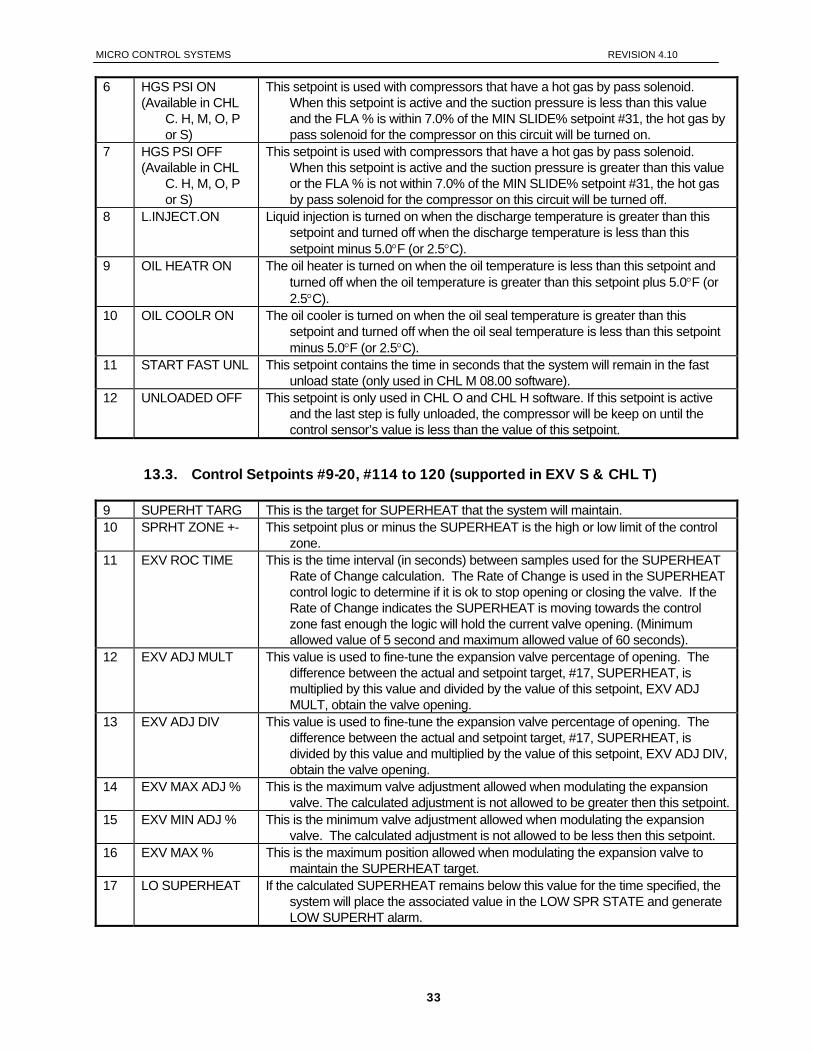
MICRO CONTROL SYSTEMS REVISION 4.10
6 HGS PSI ON (Available in CHL
C. H, M, O, P or S)
This setpoint is used with compressors that have a hot gas by pass solenoid. When this setpoint is active and the suction pressure is less than this value and the FLA % is within 7.0% of the MIN SLIDE% setpoint #31, the hot gas by pass solenoid for the compressor on this circuit will be turned on.
7 HGS PSI OFF (Available in CHL
C. H, M, O, P or S)
This setpoint is used with compressors that have a hot gas by pass solenoid. When this setpoint is active and the suction pressure is greater than this value or the FLA % is not within 7.0% of the MIN SLIDE% setpoint #31, the hot gas by pass solenoid for the compressor on this circuit will be turned off.
8 L.INJECT.ON Liquid injection is turned on when the discharge temperature is greater than this setpoint and turned off when the discharge temperature is less than this setpoint minus 5.0°F (or 2.5°C).
9 OIL HEATR ON The oil heater is turned on when the oil temperature is less than this setpoint and turned off when the oil temperature is greater than this setpoint plus 5.0°F (or 2.5°C).
10 OIL COOLR ON The oil cooler is turned on when the oil seal temperature is greater than this setpoint and turned off when the oil seal temperature is less than this setpoint minus 5.0°F (or 2.5°C).
11 START FAST UNL This setpoint contains the time in seconds that the system will remain in the fast unload state (only used in CHL M 08.00 software).
12 UNLOADED OFF This setpoint is only used in CHL O and CHL H software. If this setpoint is active and the last step is fully unloaded, the compressor will be keep on until the control sensor’s value is less than the value of this setpoint.
13.3. Control Setpoints #9-20, #114 to 120 (supported in EXV S & CHL T)
9 SUPERHT TARG This is the target for SUPERHEAT that the system will maintain. 10 SPRHT ZONE +- This setpoint plus or minus the SUPERHEAT is the high or low limit of the control
zone. 11 EXV ROC TIME This is the time interval (in seconds) between samples used for the SUPERHEAT
Rate of Change calculation. The Rate of Change is used in the SUPERHEAT control logic to determine if it is ok to stop opening or closing the valve. If the Rate of Change indicates the SUPERHEAT is moving towards the control zone fast enough the logic will hold the current valve opening. (Minimum allowed value of 5 second and maximum allowed value of 60 seconds).
12 EXV ADJ MULT This value is used to fine-tune the expansion valve percentage of opening. The difference between the actual and setpoint target, #17, SUPERHEAT, is multiplied by this value and divided by the value of this setpoint, EXV ADJ MULT, obtain the valve opening.
13 EXV ADJ DIV This value is used to fine-tune the expansion valve percentage of opening. The difference between the actual and setpoint target, #17, SUPERHEAT, is divided by this value and multiplied by the value of this setpoint, EXV ADJ DIV, obtain the valve opening.
14 EXV MAX ADJ % This is the maximum valve adjustment allowed when modulating the expansion valve. The calculated adjustment is not allowed to be greater then this setpoint.
15 EXV MIN ADJ % This is the minimum valve adjustment allowed when modulating the expansion valve. The calculated adjustment is not allowed to be less then this setpoint.
16 EXV MAX % This is the maximum position allowed when modulating the expansion valve to maintain the SUPERHEAT target.
17 LO SUPERHEAT If the calculated SUPERHEAT remains below this value for the time specified, the system will place the associated value in the LOW SPR STATE and generate LOW SUPERHT alarm.
33
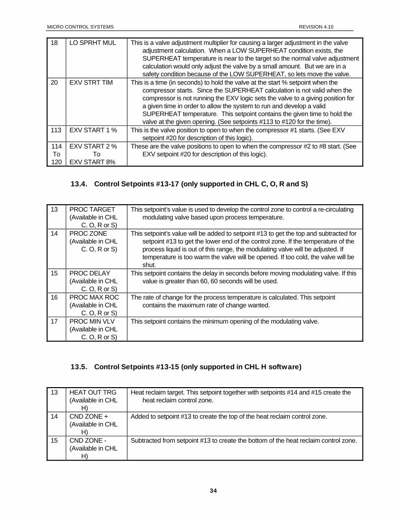
MICRO CONTROL SYSTEMS REVISION 4.10
18 LO SPRHT MUL This is a valve adjustment multiplier for causing a larger adjustment in the valve adjustment calculation. When a LOW SUPERHEAT condition exists, the SUPERHEAT temperature is near to the target so the normal valve adjustment calculation would only adjust the valve by a small amount. But we are in a safety condition because of the LOW SUPERHEAT, so lets move the valve.
20 EXV STRT TIM This is a time (in seconds) to hold the valve at the start % setpoint when the compressor starts. Since the SUPERHEAT calculation is not valid when the compressor is not running the EXV logic sets the valve to a giving position for a given time in order to allow the system to run and develop a valid SUPERHEAT temperature. This setpoint contains the given time to hold the valve at the given opening. (See setpoints #113 to #120 for the time).
113 EXV START 1 % This is the valve position to open to when the compressor #1 starts. (See EXV setpoint #20 for description of this logic).
114 To 120
EXV START 2 % To
EXV START 8%
These are the valve positions to open to when the compressor #2 to #8 start. (See EXV setpoint #20 for description of this logic).
13.4. Control Setpoints #13-17 (only supported in CHL C, O, R and S)
13 PROC TARGET
(Available in CHL C. O, R or S)
This setpoint’s value is used to develop the control zone to control a re-circulating modulating valve based upon process temperature.
14 PROC ZONE (Available in CHL
C. O, R or S)
This setpoint’s value will be added to setpoint #13 to get the top and subtracted for setpoint #13 to get the lower end of the control zone. If the temperature of the process liquid is out of this range, the modulating valve will be adjusted. If temperature is too warm the valve will be opened. If too cold, the valve will be shut.
15 PROC DELAY (Available in CHL
C. O, R or S)
This setpoint contains the delay in seconds before moving modulating valve. If this value is greater than 60, 60 seconds will be used.
16 PROC MAX ROC (Available in CHL
C. O, R or S)
The rate of change for the process temperature is calculated. This setpoint contains the maximum rate of change wanted.
17 PROC MIN VLV (Available in CHL
C. O, R or S)
This setpoint contains the minimum opening of the modulating valve.
13.5. Control Setpoints #13-15 (only supported in CHL H software)
13 HEAT OUT TRG
(Available in CHL H)
Heat reclaim target. This setpoint together with setpoints #14 and #15 create the heat reclaim control zone.
14 CND ZONE + (Available in CHL
H)
Added to setpoint #13 to create the top of the heat reclaim control zone.
15 CND ZONE - (Available in CHL
H)
Subtracted from setpoint #13 to create the bottom of the heat reclaim control zone.
34
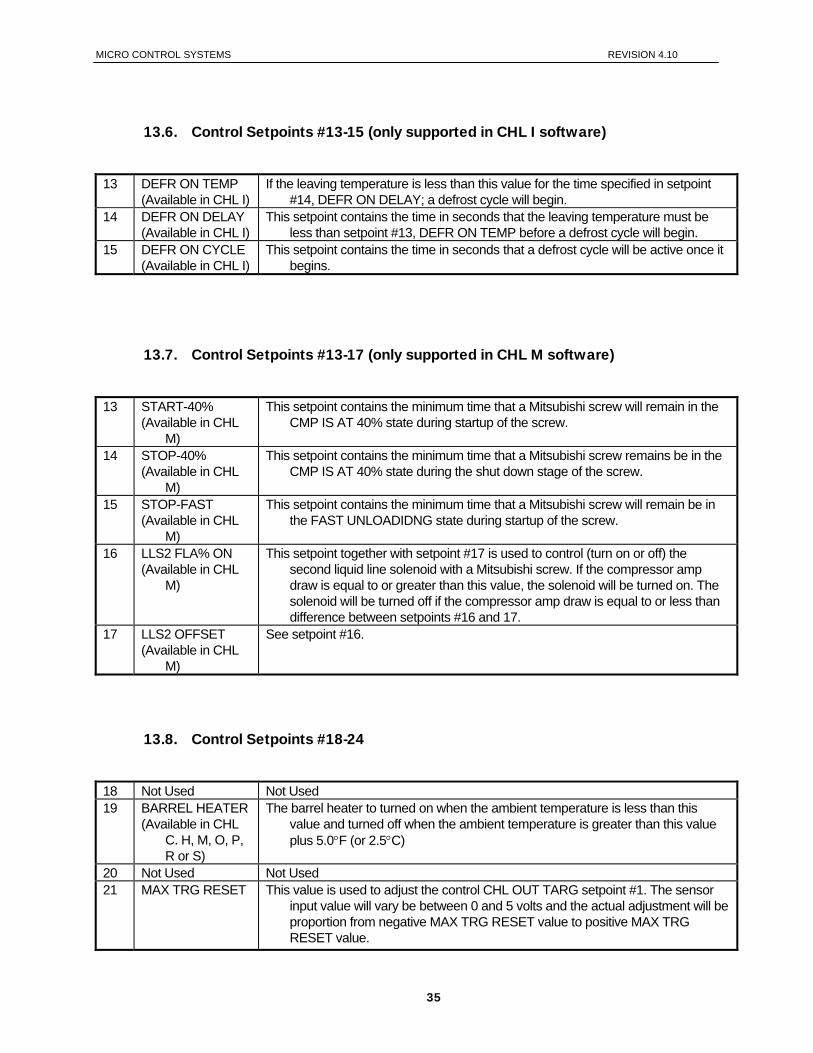
MICRO CONTROL SYSTEMS REVISION 4.10
13.6. Control Setpoints #13-15 (only supported in CHL I software)
13 DEFR ON TEMP
(Available in CHL I) If the leaving temperature is less than this value for the time specified in setpoint
#14, DEFR ON DELAY; a defrost cycle will begin. 14 DEFR ON DELAY
(Available in CHL I) This setpoint contains the time in seconds that the leaving temperature must be
less than setpoint #13, DEFR ON TEMP before a defrost cycle will begin. 15 DEFR ON CYCLE
(Available in CHL I) This setpoint contains the time in seconds that a defrost cycle will be active once it
begins.
13.7. Control Setpoints #13-17 (only supported in CHL M software)
13 START-40%
(Available in CHL M)
This setpoint contains the minimum time that a Mitsubishi screw will remain in the CMP IS AT 40% state during startup of the screw.
14 STOP-40% (Available in CHL
M)
This setpoint contains the minimum time that a Mitsubishi screw remains be in the CMP IS AT 40% state during the shut down stage of the screw.
15 STOP-FAST (Available in CHL
M)
This setpoint contains the minimum time that a Mitsubishi screw will remain be in the FAST UNLOADIDNG state during startup of the screw.
16 LLS2 FLA% ON (Available in CHL
M)
This setpoint together with setpoint #17 is used to control (turn on or off) the second liquid line solenoid with a Mitsubishi screw. If the compressor amp draw is equal to or greater than this value, the solenoid will be turned on. The solenoid will be turned off if the compressor amp draw is equal to or less than difference between setpoints #16 and 17.
17 LLS2 OFFSET (Available in CHL
M)
See setpoint #16.
13.8. Control Setpoints #18-24
18 Not Used Not Used 19 BARREL HEATER
(Available in CHL C. H, M, O, P, R or S)
The barrel heater to turned on when the ambient temperature is less than this value and turned off when the ambient temperature is greater than this value plus 5.0°F (or 2.5°C)
20 Not Used Not Used 21 MAX TRG RESET This value is used to adjust the control CHL OUT TARG setpoint #1. The sensor
input value will vary be between 0 and 5 volts and the actual adjustment will be proportion from negative MAX TRG RESET value to positive MAX TRG RESET value.
35
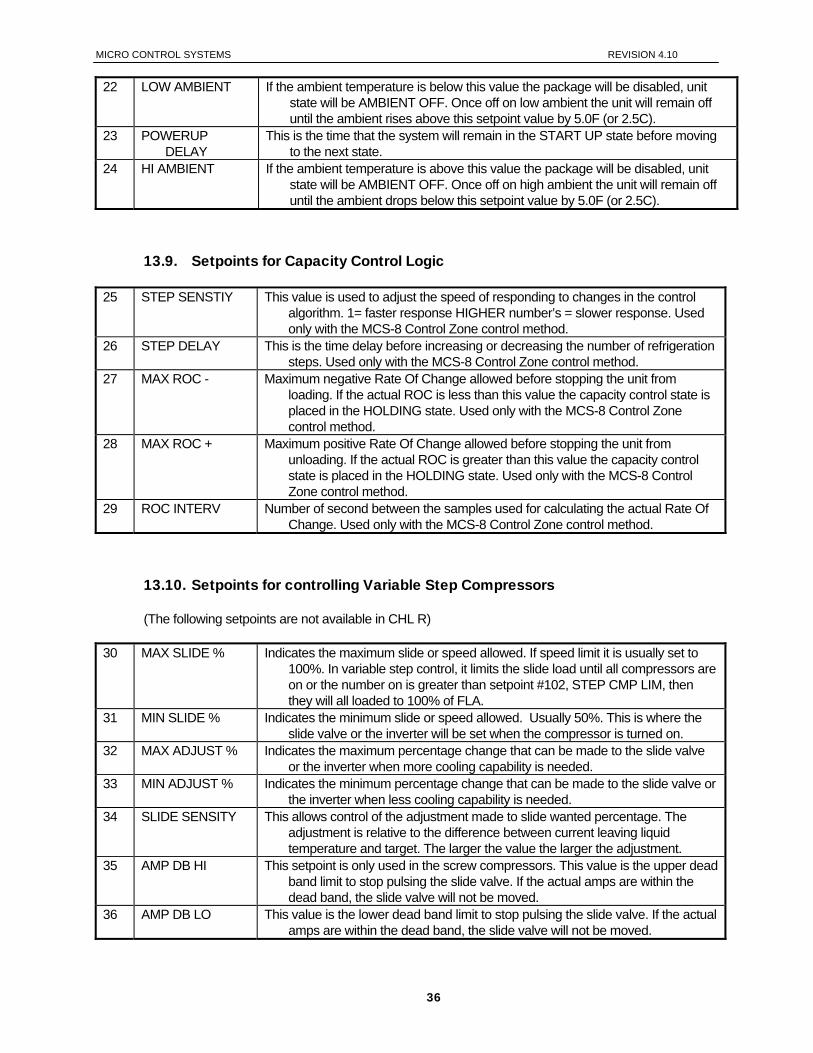
MICRO CONTROL SYSTEMS REVISION 4.10
22 LOW AMBIENT If the ambient temperature is below this value the package will be disabled, unit state will be AMBIENT OFF. Once off on low ambient the unit will remain off until the ambient rises above this setpoint value by 5.0F (or 2.5C).
23 POWERUP DELAY
This is the time that the system will remain in the START UP state before moving to the next state.
24 HI AMBIENT If the ambient temperature is above this value the package will be disabled, unit state will be AMBIENT OFF. Once off on high ambient the unit will remain off until the ambient drops below this setpoint value by 5.0F (or 2.5C).
13.9. Setpoints for Capacity Control Logic
25 STEP SENSTIY This value is used to adjust the speed of responding to changes in the control algorithm. 1= faster response HIGHER number’s = slower response. Used only with the MCS-8 Control Zone control method.
26 STEP DELAY This is the time delay before increasing or decreasing the number of refrigeration steps. Used only with the MCS-8 Control Zone control method.
27 MAX ROC - Maximum negative Rate Of Change allowed before stopping the unit from loading. If the actual ROC is less than this value the capacity control state is placed in the HOLDING state. Used only with the MCS-8 Control Zone control method.
28 MAX ROC + Maximum positive Rate Of Change allowed before stopping the unit from unloading. If the actual ROC is greater than this value the capacity control state is placed in the HOLDING state. Used only with the MCS-8 Control Zone control method.
29 ROC INTERV Number of second between the samples used for calculating the actual Rate Of Change. Used only with the MCS-8 Control Zone control method.
13.10. Setpoints for controlling Variable Step Compressors
(The following setpoints are not available in CHL R) 30 MAX SLIDE % Indicates the maximum slide or speed allowed. If speed limit it is usually set to
100%. In variable step control, it limits the slide load until all compressors are on or the number on is greater than setpoint #102, STEP CMP LIM, then they will all loaded to 100% of FLA.
31 MIN SLIDE % Indicates the minimum slide or speed allowed. Usually 50%. This is where the slide valve or the inverter will be set when the compressor is turned on.
32 MAX ADJUST % Indicates the maximum percentage change that can be made to the slide valve or the inverter when more cooling capability is needed.
33 MIN ADJUST % Indicates the minimum percentage change that can be made to the slide valve or the inverter when less cooling capability is needed.
34 SLIDE SENSITY This allows control of the adjustment made to slide wanted percentage. The adjustment is relative to the difference between current leaving liquid temperature and target. The larger the value the larger the adjustment.
35 AMP DB HI This setpoint is only used in the screw compressors. This value is the upper dead band limit to stop pulsing the slide valve. If the actual amps are within the dead band, the slide valve will not be moved.
36 AMP DB LO This value is the lower dead band limit to stop pulsing the slide valve. If the actual amps are within the dead band, the slide valve will not be moved.
36
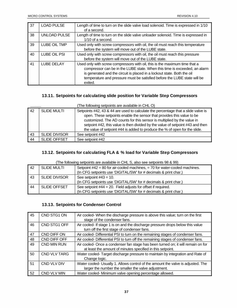
MICRO CONTROL SYSTEMS REVISION 4.10
37 LOAD PULSE Length of time to turn on the slide valve load solenoid. Time is expressed in 1/10 of a second.
38 UNLOAD PULSE Length of time to turn on the slide valve unloader solenoid. Time is expressed in 1/10 of a second.
39 LUBE OIL TMP Used only with screw compressors with oil, the oil must reach this temperature before the system will move out of the LUBE state.
40 LUBE OIL PSI Used only with screw compressors with oil, the oil must reach this pressure before the system will move out of the LUBE state.
41 LUBE DELAY Used only with screw compressors with oil, this is the maximum time that a compressor can be in the LUBE state. When this time is exceeded, an alarm is generated and the circuit is placed in a lockout state. Both the oil temperature and pressure must be satisfied before the LUBE state will be exited.
13.11. Setpoints for calculating slide position for Variable Step Compressors
........... (The following setpoints are available in CHL O) 42 SLIDE MULTI Setpoints #42, 43 & 44 are used to calculate the percentage that a slide valve is
open. These setpoints enable the sensor that provides this value to be customized. The AD counts for this sensor is multiplied by the value in setpoint #42, this value is then divided by the value of setpoint #43 and then the value of setpoint #44 is added to produce the % of open for the slide.
43 SLIDE DIVISOR See setpoint #42 44 SLIDE OFFSET See setpoint #42
13.12. Setpoints for calculating FLA & % load for Variable Step Compressors
(The following setpoints are available in CHL S, also see setpoints 98 & 99) 42 SLIDE MULTI Setpoint #42 = 80 for air-cooled machines, = 70 for water-cooled machines.
(In CFG setpoints use ‘DIGITAL/SW’ for # decimals & print char.) 43 SLIDE DIVISOR See setpoint #43 = 10.
(In CFG setpoints use ‘DIGITAL/SW’ for # decimals & print char.) 44 SLIDE OFFSET See setpoint #44 = 20. Field adjusts for offset if required.
(In CFG setpoints use ‘DIGITAL/SW’ for # decimals & print char.)
13.13. Setpoints for Condenser Control
45 CND STG1 ON Air cooled- When the discharge pressure is above this value; turn on the first stage of the condenser fans.
46 CND STG1 OFF Air cooled- If stage 1 is on and the discharge pressure drops below this value turn off the first stage of condenser fans.
47 CND DIFF ON Air cooled- Differential PSI to turn on the remaining stages of condenser fans. 48 CND DIFF OFF Air cooled- Differential PSI to turn off the remaining stages of condenser fans. 49 CND MIN RUN Air cooled- Once a condenser fan stage has been turned on; it will remain on for
at least the amount of minutes specified in this setpoint. 50 CND VLV TARG Water cooled- Target discharge pressure to maintain by integration and Rate of
Change logic. 51 CND VLV DIV Water cooled- Usually 1. Allows control of the amount the valve is adjusted. The
larger the number the smaller the valve adjustment. 52 CND VLV MIN Water cooled- Minimum valve opening percentage allowed.
37
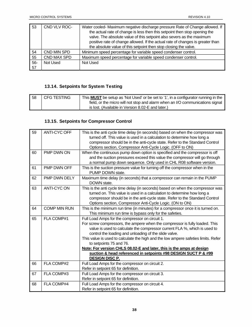
MICRO CONTROL SYSTEMS REVISION 4.10
53 CND VLV ROC- Water cooled- Maximum negative discharge pressure Rate of Change allowed. If the actual rate of change is less then this setpoint then stop opening the valve. The absolute value of this setpoint also severs as the maximum positive rate of change allowed. If the actual rate of changes is greater than the absolute value of this setpoint then stop closing the valve.
54 CND MIN SPD Minimum speed percentage for variable speed condenser control. 55 CND MAX SPD Maximum speed percentage for variable speed condenser control. 56- 57
Not Used Not Used
13.14. Setpoints for System Testing
58 CFG TESTING This MUST be setup as ‘Not Used’ or be set to ‘1’, in a configurator running in the field, or the micro will not stop and alarm when an I/O communications signal is lost. (Available in Version 8.02-E and later.)
13.15. Setpoints for Compressor Control
59 ANTI-CYC OFF This is the anti cycle time delay (in seconds) based on when the compressor was turned off. This value is used in a calculation to determine how long a compressor should be in the anti-cycle state. Refer to the Standard Control Options section, Compressor Anti-Cycle Logic. (OFF to ON)
60 PMP DWN ON When the continuous pump down option is specified and the compressor is off and the suction pressures exceed this value the compressor will go through a normal pump down sequence. Only used in CHL R08 software version.
61 PMP DWN OFF This is the suction pressure value for turning off the compressor when in the PUMP DOWN state.
62 PMP DWN DELY Maximum time delay (in seconds) that a compressor can remain in the PUMP DOWN state.
63 ANTI-CYC ON This is the anti cycle time delay (in seconds) based on when the compressor was turned on. This value is used in a calculation to determine how long a compressor should be in the anti-cycle state. Refer to the Standard Control Options section, Compressor Anti-Cycle Logic. (ON to ON)
64 COMP MIN RUN This is the minimum run time (in minutes) for a compressor once it is turned on. This minimum run time is bypass only for the safeties.
65 FLA COMP#1 Full Load Amps for the compressor on circuit 1. For screw compressors, the ampere when the compressor is fully loaded. This
value is used to calculate the compressor current FLA %, which is used to control the loading and unloading of the slide valve.
This value is used to calculate the high and the low ampere safeties limits. Refer to setpoints 75 and 76.
Note: For version CHLS 08.02-E and later, this is the amps at design suction & head referenced in setpoints #98 DESIGN SUCT P & #99 DESIGN DISC P.
66 FLA COMP#2 Full Load Amps for the compressor on circuit 2. Refer in setpoint 65 for definition.
67 FLA COMP#3 Full Load Amps for the compressor on circuit 3. Refer in setpoint 65 for definition.
68 FLA COMP#4 Full Load Amps for the compressor on circuit 4. Refer in setpoint 65 for definition.
38
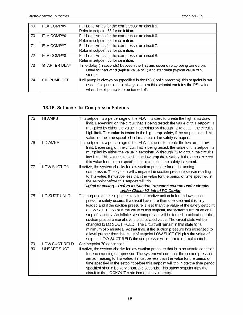
MICRO CONTROL SYSTEMS REVISION 4.10
69 FLA COMP#5 Full Load Amps for the compressor on circuit 5. Refer in setpoint 65 for definition.
70 FLA COMP#6 Full Load Amps for the compressor on circuit 6. Refer in setpoint 65 for definition.
71 FLA COMP#7 Full Load Amps for the compressor on circuit 7. Refer in setpoint 65 for definition.
72 FLA COMP#8 Full Load Amps for the compressor on circuit 8. Refer in setpoint 65 for definition.
73 STARTER DLAY Time delay (in seconds) between the first and second relay being turned on. Used for part wind (typical value of 1) and star delta (typical value of 5) starter.
74 OIL PUMP OFF If oil pump is always on (specified in the PC-Config program), this setpoint is not used. If oil pump is not always on then this setpoint contains the PSI value when the oil pump is to be turned off.
13.16. Setpoints for Compressor Safeties
75 HI AMPS This setpoint is a percentage of the FLA; it is used to create the high amp draw limit. Depending on the circuit that is being tested: the value of this setpoint is multiplied by either the value in setpoints 65 through 72 to obtain the circuit’s high limit. This value is tested in the high amp safety, if the amps exceed this value for the time specified in this setpoint the safety is tripped.
76 LO AMPS This setpoint is a percentage of the FLA; it is used to create the low amp draw limit. Depending on the circuit that is being tested: the value of this setpoint is multiplied by either the value in setpoints 65 through 72 to obtain the circuit’s low limit. This value is tested in the low amp draw safety, if the amps exceed this value for the time specified in this setpoint the safety is tripped.
77 LOW SUCTION If active, the system checks for low suction pressure for each running compressor. The system will compare the suction pressure sensor reading to this value. It must be less than the value for the period of time specified in the setpoint before this setpoint will trip.
Digital or analog – Refers to ‘Suction Pressure’ column under circuits under Chiller V8 tab of PC-Config
78 LO SUCT UNLD The purpose of this setpoint is to take corrective action before a low suction pressure safety occurs. If a circuit has more than one step and it is fully loaded and if the suction pressure is less than the value of the safety setpoint (LOW SUCTION) plus the value of this setpoint, the system will turn off one step of capacity. An infinite step compressor will be forced to unload until the suction pressure rise above the calculated value. The circuit state will be changed to LO SUCT HOLD. The circuit will remain in this state for a minimum of 5 minutes. At that time, if the suction pressure has increased to a level greater then the value of setpoint LOW SUCTION plus the value of setpoint LOW SUCT RELD the compressor will return to normal control.
79 LOW SUCT RELD See setpoint 78 description 80 UNSAFE SUCT If active, the system checks for low suction pressure that is in an unsafe condition
for each running compressor. The system will compare the suction pressure sensor reading to this value. It must be less than the value for the period of time specified in the setpoint before this setpoint will trip. Note the time period specified should be very short, 2-5 seconds. This safety setpoint trips the circuit to the LOCKOUT state immediately, no retry.
39
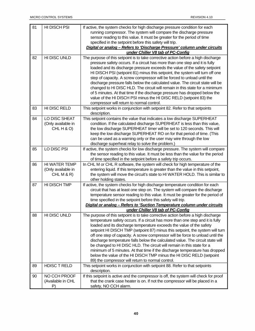
MICRO CONTROL SYSTEMS REVISION 4.10
81 HI DISCH PSI If active, the system checks for high discharge pressure condition for each running compressor. The system will compare the discharge pressure sensor reading to this value. It must be greater for the period of time specified in the setpoint before this safety will trip.
Digital or analog – Refers to ‘Discharge Pressure’ column under circuits under Chiller V8 tab of PC-Config
82 HI DISC UNLD The purpose of this setpoint is to take corrective action before a high discharge pressure safety occurs. If a circuit has more than one step and it is fully loaded and its discharge pressure exceeds the value of the safety setpoint HI DISCH PSI (setpoint 81) minus this setpoint, the system will turn off one step of capacity. A screw compressor will be forced to unload until the discharge pressure falls below the calculated value. The circuit state will be changed to HI DISC HLD. The circuit will remain in this state for a minimum of 5 minutes. At that time if the discharge pressure has dropped below the value of the HI DISCH PSI minus the HI DISC RELD (setpoint 83) the compressor will return to normal control.
83 HI DISC RELD This setpoint works in conjunction with setpoint 82. Refer to that setpoints description.
84 LO DISC SHEAT (Only available in
CHL H & O)
This setpoint contains the value that indicates a low discharge SUPERHEAT condition. If the calculated discharge SUPERHEAT is less than this value, the low discharge SUPERHEAT timer will be set to 120 seconds. This will keep the low discharge SUPERHEAT RO on for that period of time. (This can be used as a warning only or the user may wire through the low discharge superheat relay to solve the problem.)
85 LO DISC PSI If active, the system checks for low discharge pressure. The system will compare the sensor reading to this value. It must be less than the value for the period of time specified in the setpoint before a safety trip occurs.
86 HI WATER TEMP (Only available in
CHL M & R)
In CHL M or CHL R software, the system will check for high temperature of the entering liquid. If this temperature is greater than the value in this setpoint, the system will move the circuit’s state to HI WATER HOLD. This is similar to other holding states.
87 HI DISCH TMP If active, the system checks for high discharge temperature condition for each circuit that has at least one step on. The system will compare the discharge temperature sensor reading to this value. It must be greater for the period of time specified in the setpoint before this safety will trip.
Digital or analog – Refers to ‘Suction Temperature column under circuits under Chiller V8 tab of PC-Config
88 HI DISC UNLD The purpose of this setpoint is to take corrective action before a high discharge temperature safety occurs. If a circuit has more than one step and it is fully loaded and its discharge temperature exceeds the value of the safety setpoint HI DISCH TMP (setpoint 87) minus this setpoint, the system will turn off one step of capacity. A screw compressor will be force to unload until the discharge temperature falls below the calculated value. The circuit state will be changed to HI DISC HLD. The circuit will remain in this state for a minimum of 5 minutes. At that time if the discharge temperature has dropped below the value of the HI DISCH TMP minus the HI DISC RELD (setpoint 89) the compressor will return to normal control.
89 HDISC T RELD This setpoint works in conjunction with setpoint 88. Refer to that setpoints description.
90 NO CCH PROOF (Available in CHL
P)
If this setpoint is active and the compressor is off, the system will check for proof that the crank case heater is on. If not the compressor will be placed in a safety, NO CCH alarm.
40
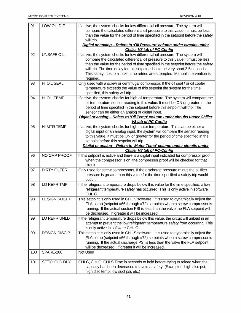
MICRO CONTROL SYSTEMS REVISION 4.10
91 LOW OIL DIF If active, the system checks for low differential oil pressure. The system will compare the calculated differential oil pressure to this value. It must be less than the value for the period of time specified in the setpoint before the safety will trip.
Digital or analog – Refers to ‘Oil Pressure’ column under circuits under Chiller V8 tab of PC-Config
92 UNSAFE OIL If active, the system checks for low differential oil pressure. The system will compare the calculated differential oil pressure to this value. It must be less than the value for the period of time specified in the setpoint before the safety will trip. The time delay for this setpoint should be very short 2-5 seconds. This safety trips to a lockout no retries are attempted. Manual intervention is required.
93 HI OIL SEAL Only used with a screw or centrifugal compressor. If the oil seal / or oil cooler temperature exceeds the value of this setpoint the system for the time specified, this safety will trip.
94 HI OIL TEMP If active, the system checks for high oil temperature. The system will compare the oil temperature sensor reading to this value. It must be ON or greater for the period of time specified in the setpoint before this setpoint will trip. The sensor can be either an analog or digital input.
Digital or analog – Refers to ‘Oil Temp’ column under circuits under Chiller V8 tab of PC-Config
95 HI MTR TEMP If active, the system checks for high motor temperature. This can be either a digital input or an analog input, the system will compare the sensor reading to this value. It must be ON or greater for the period of time specified in the setpoint before this setpoint will trip.
Digital or analog – Refers to ‘Motor Temp’ column under circuits under Chiller V8 tab of PC-Config
96 NO CMP PROOF If this setpoint is active and there is a digital input indicated for compressor proof, when the compressor is on, the compressor proof will be checked for that circuit.
97 DIRTY FILTER Only used for screw compressors. If the discharge pressure minus the oil filter pressure is greater than this value for the time specified a safety trip would occur.
98 LO REFR TMP If the refrigerant temperature drops below this value for the time specified, a low refrigerant temperature safety has occurred. This is only active in software CHL C.
98 DESIGN SUCT P This setpoint is only used in CHL S software. It is used to dynamically adjust the FLA comp (setpoint #66 through #72) setpoints when a screw compressor is running. If the actual suction PSI is less than the valve the FLA setpoint will be decreased. If greater it will be increased.
99 LO REFR UNLD If the refrigerant temperature drops below this value, the circuit will unload in an attempt to prevent the low refrigerant temperature safety from occurring. This is only active in software CHL C.
99 DESIGN DISC P This setpoint is only used in CHL S software. It is used to dynamically adjust the FLA comp (setpoint #66 through #72) setpoints when a screw compressor is running. If the actual discharge PSI is less than the valve the FLA setpoint will be decreased. If greater it will be increased.
100 SPARE-100
Not Used
101 SFTYHOLD DLY CHLC, CHLO, CHLS Time in seconds to hold before trying to reload when the capacity has been decreased to avoid a safety, (Examples: high disc psi, high disc temp, low suct psi, etc,)
41
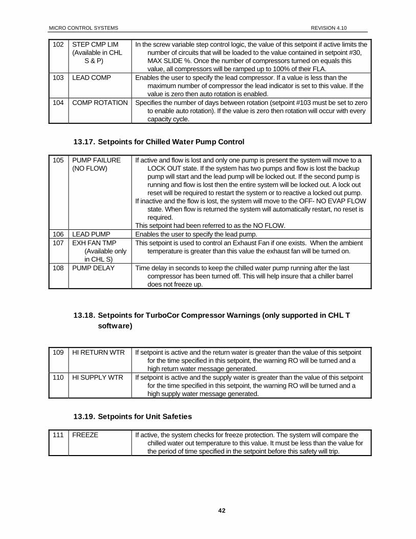
MICRO CONTROL SYSTEMS REVISION 4.10
102 STEP CMP LIM (Available in CHL
S & P)
In the screw variable step control logic, the value of this setpoint if active limits the number of circuits that will be loaded to the value contained in setpoint #30, MAX SLIDE %. Once the number of compressors turned on equals this value, all compressors will be ramped up to 100% of their FLA.
103 LEAD COMP Enables the user to specify the lead compressor. If a value is less than the maximum number of compressor the lead indicator is set to this value. If the value is zero then auto rotation is enabled.
104 COMP ROTATION Specifies the number of days between rotation (setpoint #103 must be set to zero to enable auto rotation). If the value is zero then rotation will occur with every capacity cycle.
13.17. Setpoints for Chilled Water Pump Control
105 PUMP FAILURE (NO FLOW)
If active and flow is lost and only one pump is present the system will move to a LOCK OUT state. If the system has two pumps and flow is lost the backup pump will start and the lead pump will be locked out. If the second pump is running and flow is lost then the entire system will be locked out. A lock out reset will be required to restart the system or to reactive a locked out pump.
If inactive and the flow is lost, the system will move to the OFF- NO EVAP FLOW state. When flow is returned the system will automatically restart, no reset is required.
This setpoint had been referred to as the NO FLOW. 106 LEAD PUMP Enables the user to specify the lead pump. 107 EXH FAN TMP
(Available only in CHL S)
This setpoint is used to control an Exhaust Fan if one exists. When the ambient temperature is greater than this value the exhaust fan will be turned on.
108 PUMP DELAY Time delay in seconds to keep the chilled water pump running after the last compressor has been turned off. This will help insure that a chiller barrel does not freeze up.
13.18. Setpoints for TurboCor Compressor Warnings (only supported in CHL T software)
109 HI RETURN WTR If setpoint is active and the return water is greater than the value of this setpoint
for the time specified in this setpoint, the warning RO will be turned and a high return water message generated.
110 HI SUPPLY WTR If setpoint is active and the supply water is greater than the value of this setpoint for the time specified in this setpoint, the warning RO will be turned and a high supply water message generated.
13.19. Setpoints for Unit Safeties
111 FREEZE If active, the system checks for freeze protection. The system will compare the chilled water out temperature to this value. It must be less than the value for the period of time specified in the setpoint before this safety will trip.
42
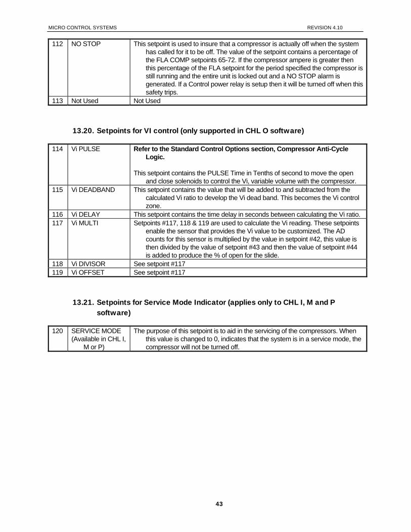
MICRO CONTROL SYSTEMS REVISION 4.10
112 NO STOP This setpoint is used to insure that a compressor is actually off when the system has called for it to be off. The value of the setpoint contains a percentage of the FLA COMP setpoints 65-72. If the compressor ampere is greater then this percentage of the FLA setpoint for the period specified the compressor is still running and the entire unit is locked out and a NO STOP alarm is generated. If a Control power relay is setup then it will be turned off when this safety trips.
113 Not Used Not Used
13.20. Setpoints for VI control (only supported in CHL O software)
114 Vi PULSE Refer to the Standard Control Options section, Compressor Anti-Cycle Logic.
This setpoint contains the PULSE Time in Tenths of second to move the open
and close solenoids to control the Vi, variable volume with the compressor. 115 Vi DEADBAND This setpoint contains the value that will be added to and subtracted from the
calculated Vi ratio to develop the Vi dead band. This becomes the Vi control zone.
116 Vi DELAY This setpoint contains the time delay in seconds between calculating the Vi ratio. 117 Vi MULTI Setpoints #117, 118 & 119 are used to calculate the Vi reading. These setpoints
enable the sensor that provides the Vi value to be customized. The AD counts for this sensor is multiplied by the value in setpoint #42, this value is then divided by the value of setpoint #43 and then the value of setpoint #44 is added to produce the % of open for the slide.
118 Vi DIVISOR See setpoint #117 119 Vi OFFSET See setpoint #117
13.21. Setpoints for Service Mode Indicator (applies only to CHL I, M and P software)
120 SERVICE MODE (Available in CHL I,
M or P)
The purpose of this setpoint is to aid in the servicing of the compressors. When this value is changed to 0, indicates that the system is in a service mode, the compressor will not be turned off.
43
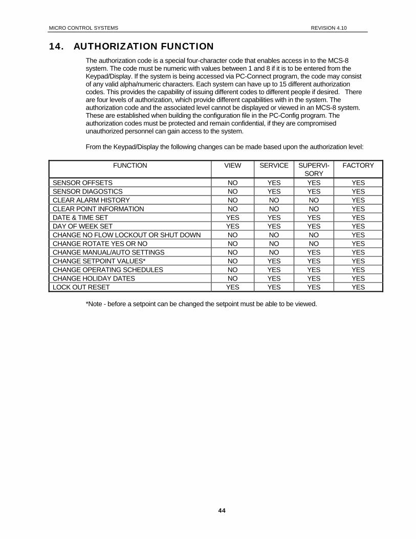
MICRO CONTROL SYSTEMS REVISION 4.10
14. AUTHORIZATION FUNCTION The authorization code is a special four-character code that enables access in to the MCS-8 system. The code must be numeric with values between 1 and 8 if it is to be entered from the Keypad/Display. If the system is being accessed via PC-Connect program, the code may consist of any valid alpha/numeric characters. Each system can have up to 15 different authorization codes. This provides the capability of issuing different codes to different people if desired. There are four levels of authorization, which provide different capabilities with in the system. The authorization code and the associated level cannot be displayed or viewed in an MCS-8 system. These are established when building the configuration file in the PC-Config program. The authorization codes must be protected and remain confidential, if they are compromised unauthorized personnel can gain access to the system. From the Keypad/Display the following changes can be made based upon the authorization level:
FUNCTION VIEW SERVICE SUPERVI-SORY
FACTORY
SENSOR OFFSETS NO YES YES YES SENSOR DIAGOSTICS NO YES YES YES CLEAR ALARM HISTORY NO NO NO YES CLEAR POINT INFORMATION NO NO NO YES DATE & TIME SET YES YES YES YES DAY OF WEEK SET YES YES YES YES CHANGE NO FLOW LOCKOUT OR SHUT DOWN NO NO NO YES CHANGE ROTATE YES OR NO NO NO NO YES CHANGE MANUAL/AUTO SETTINGS NO NO YES YES CHANGE SETPOINT VALUES* NO YES YES YES CHANGE OPERATING SCHEDULES NO YES YES YES CHANGE HOLIDAY DATES NO YES YES YES LOCK OUT RESET YES YES YES YES
*Note - before a setpoint can be changed the setpoint must be able to be viewed.
44
MICRO CONTROL SYSTEMS REVISION 4.10
15. Standard Control Options The following options are specified in the PC-Config program when building the configuration. These options are used to personalize the system to meet the individual control requirements.
15.1. General Options
Control method can be based upon the control zone strategy or upon a voltage input that indicates the number of stages to be on.
The control temperature can specify either the return or leaving sensor. Specify if the anti recycle timer should start when the compressor is turned on or turned off.
(All circuits) Number of circuits, maximum of eight. Alarm RO, this point will be turned on when ever an alarm is generated. Specify auto rotation for circuits. Low and/or high ambient shut down.
15.2. Compressor Options
Type of compressors: Reciprocating with oil, Reciprocating with out oil, Screw with oil, Scroll, Hitachi Screw, Bitzer Screw Hartford Screw Hall 85/95 Ton Screw Carlyle Screw Hanbell Screw Centrifugal Mitsubishi Screw
Four compressor steps per circuit can be supported. Compressor plus three additional steps
of either compressors or unloaders and hot gas bypass points. Note, compressor safeties relate to a circuit. If multiple compressors are on a circuit and a safety trips all compressor on that circuit will be turned off. If hot gas bypass refer to Hot Gas Bypass Option.
Specify that part winding, two RO points will be used with fixed step compressors, the first RO will be turned on with the second RO being turn on the number of seconds later that is specified in setpoint #73. (By circuit) If not part winding, only allocate one RO point for the compressor.
Type of pump down, when the compressor is off, continuous will cause the compressor to be turned on if the suction pressure rises above the setpoint value. Else, the compressor will be pumped down only when the compressor is being turned off. Note, when the compressor is started the liquid line solenoid is not opened until the suction pressure reaches the value that is contained in the pump down setpoint. A liquid line solenoid is required. (All circuits)
The liquid line solenoids may be eliminated. This is indicated in the circuit section in PC-Config program.
45
MICRO CONTROL SYSTEMS REVISION 4.10
15.3. Condenser Options
Number of condensing stages. Type of condenser:
None, RO Step Common (all compressors monitored for discharge pressure), RO Step Individual per circuit (compressor on circuit monitored for discharge pressure), RO Step Combined, circuits 1 & 2 and circuits 3 & 4 will share a condenser (compressor
on related circuits monitored for discharge pressure), All of the RO Step type condenser can have a variable speed fan per circuit, Modulating Common. This is usually used to control a water condenser with a value that
will be modulated depending on the rate of change of the discharge pressure
15.4. Chiller Barrel Heater Options
Chiller Barrel Heater, if specified a heater for the chiller barrel will be controlled based upon ambient temperature and setpoint #19, BARREL HEATER.
15.5. Hot Gas Bypass
15.5.1. Support in CHL R & I (fixed step capacity) software
Used as the first stage of capacity. The software will support up to 4 stages of capacity; compressor, two unloaders and hot gas stage. There is no specialized control for the hot gas. That is the hot gas by-pass is turned on or off based upon the capacity needs of the system. It must be assigned following the last unloader if any exist. In PC-Config, count the hot gas by-pass as an unloader.
15.5.2. Support in CHL C, H, O, P and S software
Will be turned on/off depending on pressure and/or temperature if the appropriate setpoints are active. LEAVING LIQUID SETPOINTS (LLSP) & LOW SUCTION SETPOINTS INACTIVE (LSSP)- If both setpoints are inactive the HGB is enabled when the machine is unloaded to within 7% of the minimum sidle percentage. LEAVING LIQUID SETPOINTS ACTIVE- If the LLSP is active the HGB is on when the machine is unloaded & the leaving liquid goes below the LLSP cut in. HGB is turned off when the HGB is on and the leaving liquid temperature goes above the LLSP cutout or the machine leaves the unloaded state. HGB SUCTION SETPOINTS ACTIVE- If the LSSP is active the HGB is on when the machine is unloaded & the suction pressure goes below the LSSP cut in. HGB is turned off when the HGB is on and the suction pressure goes above the LSSP cutout or the machine leaves the unloaded state. LEAVING LIQUID SETPOINTS (LLSP) & LOW SUCTION SETPOINTS ACTIVE (LSSP)- If both setpoints are active the HGB is on when the machine is unloaded and either the leaving liquid temperature goes below the LLSP cut in or the suction pressure goes below the LSSP cut in. The HGB goes off when the machine leaves the unloaded state or both the leaving liquid temperature goes above the LLSP cutout and the suction pressure goes above the LSSP cutout.
46
MICRO CONTROL SYSTEMS REVISION 4.10
15.6. Chilled Water Reset
Chilled Water Reset (CWR) is a 0 to 5 volts dc sensor input; Display Type is TRGTRST, to the MCS microprocessor. The CWR follows the following rules using setpoint #21, MAX TRG RESET: 1. If the input is 2.5 volts dc the CWR is zero. 2. At 0 volts dc the CWR is a negative value equal to the setpoint value. 3. At 5.00 volts dc the CWR is a positive value equal to the value in the setpoint. 4. For values in between 0 – 2.5 and 2.5 – 5.0 the CWR is a plus or minus value which is
proportional to the sensor input voltage.
15.7. Two Expansions Valves Option - Screws Only
15.7.1 Software CHL S08.0?-? or priorTwo expansion valves are supported in CHL V8 software. Refer to section ‘Circuit relay output sequence (examples)’ for RELAY OUTPUT order and options. When the compressor first starts, LLS1 opens after a pre pump down. LLS2 turns on at 30 percent above unloaded amps + 5 amps. LLS2 opens based on the following calculations. 1. Using setpoints for full load amps & min var step calculate UNLOADED AMPS.
UNLOADED AMPS = (FULL LOAD AMPS) X (MIN VAR STEP) 2. Using setpoint full load amps & calculated unloaded amps calculate AMP TRAVEL 30.
AMP TRAVEL 30 = [(FULL LOAD AMPS) – (UNLOADED AMPS)] X .3 3. Using UNLOADED AMPS & AMP TRAVEL 30 calculates LLS LARGE OFF.
LLS LARGE OFF = UNLOADED AMPS + AMP TRAVEL 30 4. Using LLS LARGE OFF calculate LLS LARGE ON.
LLS LARGE ON = LLS LARGE OFF + 5 15.7.2 Software CHL S08.0?-? or after. New LLS2 & LLS3 control logic.
1. Setpoint 98=LLS2 on 2. Setpoint 99=LLS3 on 3. COMP FLA% SLIDE is greater than setpoint the LLS is on. 4. COMP FLA% SLIDE is less than (setpoint-20%) LLS is off. 5. LLS3 is setup for economizer control and during safety unloading (HI PSI,HI TMP, etc.) turns
off immediately.
15.8. Oil Equalization Option – supported in CHL C, H, O, S and T software
Oil equalization occurs with common suction/common discharge systems. This feature allows for a solenoid valve to open, allowing oil to equalize between compressors. Refer to section ‘Circuit relay output sequence (examples)’ for RELAY OUTPUT order and options. If this feature is installed the micro will energize the Oil Equalization solenoid valve for 1 minute at the time a compressor is turned on.
15.9. Oil Cooler Option - supported in CHL C, H, O, S and T software
Oil cooler option can be specified for compressors with oil. This feature requires a temperature sensor to capture the oil temperature, a relay out to energize the oil cooler and the OILCOOLER ON setpoint (#10) to be active. Refer to section ‘Circuit relay output sequence (examples)’ for RELAY OUTPUT order and options.
47
MICRO CONTROL SYSTEMS REVISION 4.10
If the oil temperature is above the value in the setpoint for longer than the time specified, the relay output is energized. The relay output will remain on until the temperature is less 5.0F degrees below the setpoint value.
15.10. Oil Pump Control Option – supported in CHL C, H and O software
OIL PUMP ALWAYS ON: The oil pump will always be on when the associated compressor is on. If the oil psi drops below the value of setpoint #74, shut down the associated compressor with a LOW DIFFERENTIAL alarm. Keep the oil pump on after the compressor is turned off regardless of the reason, for the time specified in setpoint #62.
OIL PUMP CYCLES: After the compressor has been running for 2 minutes and when the discharge psi minus the suction psi is greater than the value in setpoint #74 (OIL PUMP OFF) the oil pump will be turned off. If the discharge psi minus the suction psi drops 10 psi below the value of setpoint #74 the oil pump will be turned on.
OIL PUMP LUBE ONLY: After the compressor has been running for 2 minutes and when the discharge psi minus the suction psi is greater than the value in setpoint #74 (OIL PUMP OFF) the oil pump will be turned off. If the differential psi has not been reached after 5 minutes, shut down the associated compressor with a LOW DIFFERENTIAL alarm. Once the differential psi has been reached and the oil pump turned off, if the discharge psi minus the suction psi drops 5 psi below the value of setpoint #74, shut down the associated compressor with a LOW DIFFERENTIAL alarm.
15.11. Oil Differential Calculation
For CHL H and O software this calculation is OIL PRESSURE minus DISCHARGE PRESSURE. For all other software the calculation is OIL PRESSURE minus SUCTION PRESSURE. This provides the flexibility of using oil pressure if available or if not, discharge pressure can be used in place of the oil pressure. This is set up in the circuit information section of PC-Config by pointing the oil pressure sensor to the discharge pressure sensor.
15.12. On/Off Switches
The following digital input switches can be associated with the system, their action will affect the chiller package or an individual circuit, then action will only affect that circuit:
Flow switch, if off the system has lost flow. The system wills either lock out, if NO FLOW setpoint is active, or shut down, if NO FLOW setpoint is inactive.
Pump down switch, if on and the compressor is off, will not start the compressor. If the compressor is on, the system moves to the pump down state to begin the process of turning off the compressor(s) in normal steps.
Run/Stop, if off the system will not run. This is usually wired to a RUN/STOP switch that is
manually positioned. If the system is running, the system moves all circuits (compressor) to off in normal steps.
48
MICRO CONTROL SYSTEMS REVISION 4.10
Network Run/Stop, if off the system will not run. This input is provided by another system that resides on the network. It functions in the same matter as the Run/Stop switch.
Emergency Stop switch, if on, the system will be shut down immediately and will remain
disabled until the switch is off.
15.13. Low Suction Unloading & Holding
This option is activated when the setpoint #78, LO SUCT UNLD, is active. The purpose of this option is to take corrective action prior to a safety being tripped. When the suction pressure is below the value calculated by adding the value of this setpoint to the value of the LOW SUCTION setpoint for the time specified, the system will turn on the WARNING relay output if specified in the PC-Config and take the following action: For a fixed step compressor, the system will turn off one step of capacity associated with that
compressor until that circuit is in an UNLOADED state, that is all steps except one are unloaded. The circuit (compressor) state will be LO SUCT HOLD. The circuit will remain in that state until the capacity control indicates that another step is to be unloaded or if after 5 minutes the suction pressure has turned to normal.
For an infinite step compressor, the system will begin unloading that compressor until the suction pressure rises above the calculated value. During this time the circuit (compressor) state is LO SUCT UNLOAD. Once this pressure has been reached, the circuit (compressor) state will be LO SUCT HOLD. The circuit will remain in that state until the capacity control indicates that less capacity is needed or if after 5 minutes the suction pressure has turned to normal.
Normal pressure is the value calculated by adding the value of the LO SUCT RELD setpoint 79 to the value of the LOW SUCTION setpoint 77. Refer to setpoint #78 and 79 for additional information.
15.14. High Discharge Pressure Unloading & Holding
This option is activated when the setpoint #82, HI DISC UNLD, is active. The purpose of this option is to take corrective action prior to a safety being tripped. When the discharge pressure is above the value calculated by subtracting the value of this setpoint from the value of the HI DISCH PSI setpoint for the time specified, the system will turn on the WARNING relay output if specified in the PC-Config and take the following action: For a fixed step compressor, the system will turn off one step of capacity associated with that
compressor until that circuit is in an UNLOADED state, that is all steps except one are unloaded. The circuit (compressor) state will be HI DISC HOLD. The circuit will remain in that state until the capacity control indicates that another step is to be unloaded or if after 5 minutes the discharge pressure has turned to normal.
For an infinite step compressor, the system will begin unloading that compressor until the discharge pressure drops below the calculated value. During this time the circuit (compressor) state is HI DISC UNLOAD. Once this pressure has been reached, the circuit (compressor) state will be HI DISC HOLD. The circuit will remain in that state until the capacity control indicates that less capacity is needed or if after 5 minutes the discharge pressure has turned to normal.
Normal pressure is the value calculated by subtracting the value of the HI DISC RELD setpoint 83 to the value of the HI DISC PSI setpoint 81.
49
MICRO CONTROL SYSTEMS REVISION 4.10
Refer to setpoint #82 and 83 for additional information.
15.15. High Discharge Temperature Unloading & Holding
This option is activated when the setpoint #88, HI DISC UNLD, is active. The purpose of this option is to take corrective action prior to a safety being tripped. When the discharge temperature is above the value calculated by subtracting the value of this setpoint from the value of the HI DISCH TMP setpoint for the time specified, the system will turn on the WARNING relay output if specified in the PC-Config and take the following action: For a fixed step compressor, the system will turn off one step of capacity associated with that
compressor until that circuit is in an UNLOADED state, that is all steps except one are unloaded. The circuit (compressor) state will be HI DISC HOLD. The circuit will remain in that state until the capacity control indicates that another step is to be unloaded or if after 5 minutes the discharge temperature has turned to normal.
For an infinite step compressor, the system will begin unloading that compressor until the discharge temperature drops below the calculated value. During this time the circuit (compressor) state is HI DISC UNLOAD. Once this temperature has been reached, the circuit (compressor) state will be HI DISC HOLD. The circuit will remain in that state until the capacity control indicates that less capacity is needed or if after 5 minutes the discharge temperature has turned to normal.
Normal pressure is the value calculated by subtracting the value of the HI DISC RELD setpoint 89 to the value of the HI DISC TMP setpoint 87. Refer to setpoint #88 and 89 for additional information.
15.16. High Ampere Unloading & Holding – supported in CHL I, M and R software
This option is activated when the setpoint #75, HI AMPS %, is active. This option can only be active for fixed step compressors. The purpose of this option is to take corrective action prior to a safety being tripped. When the amp draw is with in one-half of the calculated HI AMP safety value, the system will turn on the WARNING relay output if specified in the PC-Config and take the following action: • For a fixed step compressor, the system will turn off one step of capacity associated with that
compressor until that circuit is in an UNLOADED state, that is all steps except one are unloaded. The circuit (compressor) state will be HI AMP HOLD. The circuit will remain in that state until the capacity control indicates that another step is to be unloaded or if after 5 minutes the amp draw has turned to normal.
15.17. Low Water Temperature Unloading & Holding
The purpose of this option is to take corrective action prior to the freeze safety being tripped. When the leaving liquid temperature is with in 1.5F or .8C degrees of the freeze safety, the system will turn on the WARNING relay output if specified in the PC-Config and take the following action: For a fixed step compressor, the system will turn off one step of capacity associated with that
compressor until that circuit is in an UNLOADED state, that is all steps except one are unloaded. The circuit (compressor) state will be LO TMP HOLD. The circuit will remain in that state until the capacity control indicates that another step is to be unloaded or if after 5 minutes the leaving liquid temperature has turned to normal.
50
MICRO CONTROL SYSTEMS REVISION 4.10
For an infinite step compressor, the system will begin unloading that compressor until the leaving liquid temperature rises above the calculated value. During this time the circuit (compressor) state is LO TMP UNLOAD. Once the leaving liquid temperature has been reached, the circuit (compressor) state will be LO TMP HOLD. The circuit will remain in that state until the capacity control indicates that less capacity is needed or if after 5 minutes the leaving liquid temperature has turned to normal.
Normal leaving liquid temperature is the value calculated by adding 3.0F or 1.6C to the freeze safety trip value. Refer to setpoint #78 and 79 for additional information.
15.18. Energy Efficient Compressor Staging – Screw only
In a multi-screw package, it may be more efficient to run the screws at less than 100% of their FLA until all of the screws have been turned on or if setpoint #102 is active, the number that is contained in this setpoint. The following setpoints will be used to control the screw compressor staging: • Setpoint #30, MAX SLIDE %, contains the maximum slide percentage, based upon amp draw,
FLA before the system will bring on the next compressor. • Setpoint #31, MIN SLIDE %, contains the minimum slide percentage, based upon amp draw,
FLA before the system will reduce the number of compressor that are on. • Setpoint #102, STEP CMP LIM, indicates when the system will stop using the value in setpoint
#33 and use 100%. For example if the MAX SLIDE % is 80% and the MIN SLIDE % is 40 with setpoint #102 inactive, a two-screw compressor system would be ramped up as follows:
Compressor 1 will be started at 40% and increased up to 80%. If more capacity is needed the second compressor will be started at 40% and the first compressor decreased to 40%. The two compressors will then have their slide positions changed together. Since there are only two compressors, they will be ramped together up to 100%. If both compressors are at 40% and less capacity is needed, one compressor will be turned off and the other increased to 80%.
For example if the MAX SLIDE % is 75.0%, MIN SLIDE % is 45.0% and #102 = 2,
The system will bring on the first compressor at 45% of FLA and ramp it from 45 up to 75% of FLA. This will provide the 30 to 50% of slide movement. If more capacity is needed the second compressor will be started. Since setpoint #102 is equal to 2, the maximum will now be 100%; Compressors 1 and 2’s slide will be varied from 45 to 100% of FLA. If more capacity is needed, a third compressor will be turned on. This will continue until all compressors are on. If less capacity is needed, compressors will be turned off in the same manner. Note: stage 1 will be varied from 45 to 75% all other stages will be varied from 45 to 100%.
This provides the user with additional capabilities in fine-tuning the efficiency of a screw compressor.
15.19. Chilled Water Pump Control
The system will support a chilled water pump plus a back up. These must be set up in the PC-Config program.
51
MICRO CONTROL SYSTEMS REVISION 4.10
If setpoint #105, PUMP FAILURE, is active and flow is lost and only one pump is present the system will move to a LOCK OUT state. If the system has two pumps and flow is lost the backup pump will start and the lead pump will be locked out. If the second pump is running and flow is lost then the entire system will be locked out. A lock out reset will be required to restart the system or to reactive a locked out pump. If this setpoint is inactive and the flow is lost, the system will move to the OFF- NO EVAP FLOW state. When flow is returned the system will automatically restart, no reset is required. Setpoint #106, LEAD PUMP, indicates which pump is the lead pump.
15.20. Process Pump & Heat Exchanger Control (not supported in CHL M)
The process pump is on whenever the chilled water pump is on. A control zone is developed for the process temperature by adding and subtracting the value in setpoint #14 (PROC ZONE) to setpoint #13 (PROC TARGET). The process temperature is maintained with in this zone by modulating the control valve with a 0-10Vdc analog output signal.
15.21. Control Power Relay –No Stop
This option provides the capability of interrupting the power supply to the compressors in the system. A relay output, referred to as the control relay, must be wired so that when it is off no power reaches the compressors. This is a safety measure that will insure that the compressors are off then the system calls for them to be off. The relay output must be indicated in the PC-Config program and setpoint 112, NO STOP, must be active. The system will continually monitor the amp draw of compressors that the system has in an off state. The system will calculate the minimum amp draw by multiplying the FLA for that compressor times the percentage value in the NO STOP setpoint. If the amp draw is greater than this value for the time specified; the system will turn the control relay off, generate a NO STOP alarm and place the system in a lockout state. This provides an additional level of protection.
15.22. Part Wind or Star Delta Starter
Either a part winding or star delta type of compressor starter is supported. This option is specified in the PC-Config program and will require two successive relay output points. When this option is specified, setpoint #73, STARTER DLAY, must contain the delay in seconds before the second relay output is turned on. This delay is normally 1 second for part winding or 5 seconds for a star delta starter. With this option, when a compressor is to be turned on, the first relay output is turned on and the system will wait the time specified in setpoint 73 before the second relay output is turned on.
15.23. Low & High Ambient Shutdown
The system supports both a low and a high ambient shut down. This option requires an ambient temperature sensor and both LOW AMB OFF setpoint (#24) and HIGH AMB OFF setpoint (#26). The AMBIENT OFF state is entered when the ambient temperature falls below the LOW AMB OFF setpoint (#24) or is above the HIGH AMB OFF setpoint (#26). The system will remain in this state until the ambient temperature rises 5.0F (or 2.5C) above the LOW AMB OFF setpoint value or drops 5.0F (or 2.5C) below the HIGH AMB OFF setpoint value. When the chiller is in this state, the individual circuit states if active are moved to the CMP IS OFF state through the normal staging function. One capacity STEP will be moved per second.
52
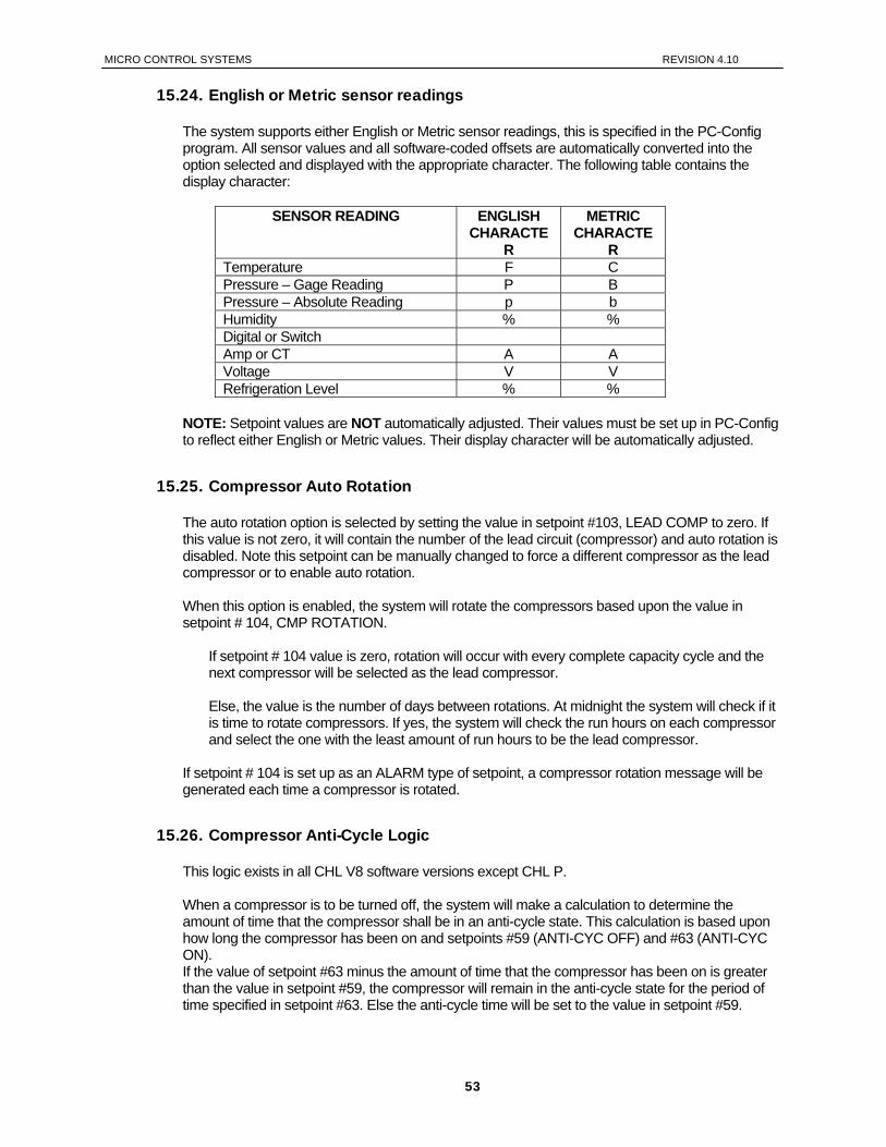
MICRO CONTROL SYSTEMS REVISION 4.10
15.24. English or Metric sensor readings
The system supports either English or Metric sensor readings, this is specified in the PC-Config program. All sensor values and all software-coded offsets are automatically converted into the option selected and displayed with the appropriate character. The following table contains the display character:
SENSOR READING ENGLISH CHARACTE
R
METRIC CHARACTE
R Temperature F C Pressure – Gage Reading P B Pressure – Absolute Reading p b Humidity % % Digital or Switch Amp or CT A A Voltage V V Refrigeration Level % %
NOTE: Setpoint values are NOT automatically adjusted. Their values must be set up in PC-Config to reflect either English or Metric values. Their display character will be automatically adjusted.
15.25. Compressor Auto Rotation
The auto rotation option is selected by setting the value in setpoint #103, LEAD COMP to zero. If this value is not zero, it will contain the number of the lead circuit (compressor) and auto rotation is disabled. Note this setpoint can be manually changed to force a different compressor as the lead compressor or to enable auto rotation. When this option is enabled, the system will rotate the compressors based upon the value in setpoint # 104, CMP ROTATION.
If setpoint # 104 value is zero, rotation will occur with every complete capacity cycle and the next compressor will be selected as the lead compressor. Else, the value is the number of days between rotations. At midnight the system will check if it is time to rotate compressors. If yes, the system will check the run hours on each compressor and select the one with the least amount of run hours to be the lead compressor.
If setpoint # 104 is set up as an ALARM type of setpoint, a compressor rotation message will be generated each time a compressor is rotated.
15.26. Compressor Anti-Cycle Logic
This logic exists in all CHL V8 software versions except CHL P. When a compressor is to be turned off, the system will make a calculation to determine the amount of time that the compressor shall be in an anti-cycle state. This calculation is based upon how long the compressor has been on and setpoints #59 (ANTI-CYC OFF) and #63 (ANTI-CYC ON). If the value of setpoint #63 minus the amount of time that the compressor has been on is greater than the value in setpoint #59, the compressor will remain in the anti-cycle state for the period of time specified in setpoint #63. Else the anti-cycle time will be set to the value in setpoint #59.
53
MICRO CONTROL SYSTEMS REVISION 4.10
For example: A compressor has been running for 180 seconds #59 (ANTI-CYC OFF) = 300 seconds #63 (ANTI-CYC ON) = 600 seconds 600 – 180 = 420 this is greater than setpoint #59; therefore, the anti-cycle timer will be set to 600 seconds, the value of setpoint #63. If the compressor had been running for 12 minutes (720 seconds) 600 – 720 = -120 this is less than setpoint #59; therefore, the anti-cycle timer will be set to 300 seconds, the value of setpoint #59.
If the controller losses power, the length of time that the system was down will be taken into consideration when determining whether the compressor should be in an anti-cycle state and for how long.
15.27. Warning & Alarm Relay Outputs Warning Relay Output will be turned on whenever the system generates a warning type of message. These messages are:
LOW REFR TEMP UNLOAD LOW SUCT PSI UNLOAD HIGH DISC TEMP UNLOAD LOW SUCT RELOAD LOW DISC RELOAD CICRUIT IS IN A SAFETY STATE
The system will continue to run and no safeties have been tripped. Warning Relay Output will also be turned on whenever a circuit is placed in a safety state. Alarm Relay Output will be turned on whenever the system generates an alarm type of message. This indicates that a safety or lockout condition has occurred.
15.28. Vi Port Control Logic (Open Drive Screw only) The internal volume (Vi) of the open drive screw can be dynamically varied to obtain maximum efficiency by opening and closing solenoids that control the Vi. These solenoids are pulsed and the duration of each pulse is contained in setpoint #114 (Vi PULSE). Calculate a ratio of discharge pressure divided by suction pressure. This ratio is blocked between 50 and 22. The value of setpoint #115(Vi DEADBAND) is added to and subtracted from this ratio to develop a control zone. The control zone will be recalculated based upon the time in setpoint #116(Vi DELAY). The Vi reading is provided by a special sensor refer to setpoints #117, #118 and #119. The system will pulse the open or close solenoids to keep the Vi reading within the calculated control zone.
Only Supported in CHL O08.00-* software
15.29. Operating Schedules
Two operating schedules per each day of the week and 8 holidays are supported. Each schedule contains a start and end time, if the time and day of the system is with in these limits the schedule is true and the system will be allowed to run. If not, the system will be off due to schedule.
54
MICRO CONTROL SYSTEMS REVISION 4.10
15.30. High Temperature Warning for TUBRO COR (CHT 008-08)
The option to test for high temperature in either/both the return or supply water has been added. If either of these conditions exits, the WARNING RO will be turned on; no other action will be taken. When the temperature returns to less than this threshold, the WARNING RO will be turned off. (Note: other conditions can also affect the WARNING RO status.) Two new setpoints must be active and set up as ALARM type of setpoint in the PC-Config program. This will enable the time (sec) value to be entered. The time value indicates the time that the temperature must stay above the setpoint value before the condition is true. (Note: this is NOT the Safety Down Time (Min) field.) The time can also be changed via PC-Connect in a live unit. • Setpoint #109 RETURN WARNG, when the return water temperature is equal to or greater
than this setpoint’s value for the time specified, the WARNING RO will be turned on.
• Setpoint #110 SUPPLY WARNG, when the supply water temperature is equal to or greater than this setpoint’s value for the time specified, the WARNING RO will be turned on.
When the temperature is less than the value in its associate setpoint, the system will not call for the WARNING RO to be turned on.
15.31. Mod-Motor Limit Control For Flooded Chiller
This option was added for Dunham-Bush flooded chillers and is only supported in CHL S software. The Mod-Motor is a self-contained device that modulates a valve to controls the level in a flooded chiller barrel base on a level sensor. The MCS-8 controls two relay outputs that change the limits on the movement of the Mod-Motor (The relay outputs change resistance on a input to the Mod-Motor. These relay outputs must be consecutive relays and are setup in the general section of the PC-Config for CHL V8. When none or one compressor is on, the first Mod-Motor relay output is turned on and the second Mod-Motor relay output is off.
When 2 or more compressors are on, first Mod-Motor relay output is turned off. The second Mod-Motor relay output will be turned on if the suction pressure is greater than 85.0 psi (5.8 if metric) and the discharge suction pressure differential is less than 30.0 psi (2.0 if metric). Or if the second Mod-Motor relay output is already on and the suction pressure is greater than 80.0 psi (5.8 if metric) and the discharge suction pressure differential is less than 35.0 psi (2.4 if metric). If neither of the above is true, then the second Mod-Motor relay output will be turned off.
15.32. Compressor
The compressor with the least number of TOTAL RUN HOURS will become the lead. Refer to Setpoints #103 & #104.
15.33. Exhaust Fan (This is only available in CHL S 08.02 – B or greater)
If an Exhaust Fan exists, its status will be checked every 120 seconds. It will be turned on if any of the following conditions exist:
o Exhaust fan digital input is on Or
o Ambient temperature is greater than the valve in setpoint #107. The setpoint must be active and a sensor input must be setup that reads the ambient temperature.
55
MICRO CONTROL SYSTEMS REVISION 4.10
The exhaust fan will be turned off if the digital input exists, the input is off and the ambient temperature if used is 2.5°F (or .8°C) below the setpoint #107.
15.34. Ice Mode (This is only available in CHL S 08.11-A or greater)
When this new option is selected the Target Reset input becomes a digital input. When the input is ON, the target reset sensor is set to setpoint #21 value, until leaving water temp falls below setpoint #1 and then we’ll turn off the unit until the digital input cycles off. The chilled water pump is also turned off when done making ice. When the digital input is OFF, the target reset sensor is set to 0.0 and the chiller runs as normal. When the ICE MODE terminates on temp, we generate an alarm to indicate this. (TMP OFF-ICE MADE).
56

MICRO CONTROL SYSTEMS REVISION 4.10
16. MCS-8 Alarms and Safeties
16.1. Introduction
There are three types of alarms that are generated by the MCS-8 control logic: Information only alarms, MCS-8 system alarms and Chiller setpoint safety alarms.
All of the alarms have the same format. The alarm is identified and it is date time stamped. Alarms can be viewed from the MCS-8 by pressing the ALARM STATUS (4) key or from the PC-Connect program.
16.2. Information only alarms
16.2.1. System generated alarms
The following alarms are generated to provide information; they will not cause a change in the control algorithm such as a lock out condition or a relay output being forced off.
POWER FAILED POWER RETURNED COMPUTER RESET LCD FAILURE HW DATE INVALID HW TIME INVALID SW DATE INVALID SW TIME INVALID RAM INTEGRITY WATCHDOG RESET
16.2.2. Alarms as a result of individual action
The following alarms indicate that an individual took action:
ALARMS CLEARED STPT CHANGED RO MANUAL AO MANUAL SI MANUAL POINT INFO CLEAR CLOCK SET CFG DOWNLOADED
16.2.3. Alarms generated by the control algorithm
The following alarms indicate that the control algorithm took action:
ROTATED LEAD DAYLIGHT SAVINGS
57
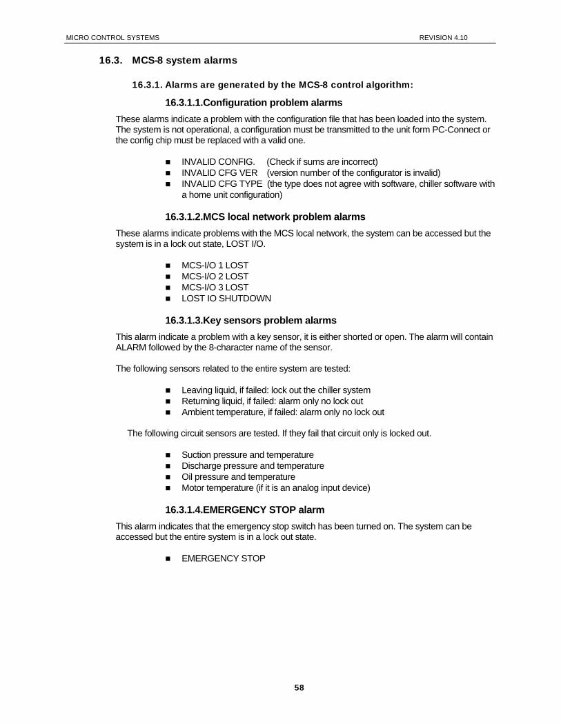
MICRO CONTROL SYSTEMS REVISION 4.10
16.3. MCS-8 system alarms
16.3.1. Alarms are generated by the MCS-8 control algorithm:
16.3.1.1.Configuration problem alarms These alarms indicate a problem with the configuration file that has been loaded into the system. The system is not operational, a configuration must be transmitted to the unit form PC-Connect or the config chip must be replaced with a valid one.
INVALID CONFIG. (Check if sums are incorrect) INVALID CFG VER (version number of the configurator is invalid) INVALID CFG TYPE (the type does not agree with software, chiller software with
a home unit configuration)
16.3.1.2.MCS local network problem alarms These alarms indicate problems with the MCS local network, the system can be accessed but the system is in a lock out state, LOST I/O.
MCS-I/O 1 LOST MCS-I/O 2 LOST MCS-I/O 3 LOST LOST IO SHUTDOWN
16.3.1.3.Key sensors problem alarms
This alarm indicate a problem with a key sensor, it is either shorted or open. The alarm will contain ALARM followed by the 8-character name of the sensor. The following sensors related to the entire system are tested:
Leaving liquid, if failed: lock out the chiller system Returning liquid, if failed: alarm only no lock out Ambient temperature, if failed: alarm only no lock out
The following circuit sensors are tested. If they fail that circuit only is locked out.
Suction pressure and temperature Discharge pressure and temperature Oil pressure and temperature Motor temperature (if it is an analog input device)
16.3.1.4.EMERGENCY STOP alarm
This alarm indicates that the emergency stop switch has been turned on. The system can be accessed but the entire system is in a lock out state.
EMERGENCY STOP
58

MICRO CONTROL SYSTEMS REVISION 4.10
16.4. Setpoint safety alarms
16.4.1. Introduction
The MCS-8 chiller algorithm incorporates a number of safety checks to ensure that the various components that make up the chiller package are not damaged. These types of safeties are based upon setpoints. When a safety trips for the first time, the compressor will be set to “SAFETY TRIPPED” state. The compressor will remain in “SAFETY TRIPPED” state for ten minutes and then move to the “CMP IS OFF” state where the compressor will be allowed to run if required. If the same safety trips occurs again within two hours of the first trip, the compressor will be set to “CMP LOCKED OUT” state, which requires a manual reset to restart the compressor. In this matter the MCS-8 attempts to take corrective action to protect the compressors but avoid nuisance trips. The time in the safety state and the time between safeties are specified in the individual setpoints. This enables the times to be unique for each lock out setpoint.
16.4.2. Sensor inputs used in conjunction with MCS-8 setpoint safeties:
Suction Pressure
Pressure transducer to read the suction pressure. (Optional digital input)
Discharge Pressure
Pressure transducer to read the discharge pressure. (Optional digital input)
Oil Pressure
Pressure to read the oil pressure (optional digital input)
Oil Differential Pressure
Calculated valve of the oil pressure as follows: - Fixed step compressors, oil psi minus suction psi - Screws with oil pump, Oil psi minus discharge psi - Screws without oil pump, discharge psi minus suction psi
Oil Temperature
Either a temperature sensor or a digital input that indicates when a high temperature condition exists.
Discharge Temperature
Either a temperature sensor or a digital input that indicates when a high temperature condition exists.
Motor Temperature
Either a temperature sensor or a digital input that indicates when a high temperature condition exists.
Motor Amps
Sensor input that measures AMP draw of the compressor. (Optional digital input)
Motor Fault
A digital input that indicates when a motor fault condition exists or an analog sensor that will read resistance value. If an analog sensor, a setpoint is required that contains the resistance value that the sensor will indicate on safety trip. This is a general fault indicator, that may have been caused by high temperature, amp draw etc.
59
MICRO CONTROL SYSTEMS REVISION 4.10
Liquid Temperature
Temperature sensor that can be used to detect a freeze condition
Compress Proof
A digital input that when on indicates that a compressor is running.
Flow Switch
A digital input that indicates that flow through the chiller barrel exists. There can be one switch per chiller or one for each circuit.
16.4.3. Setpoint safeties
For a safety to be interrogated, both the associated sensor input and the lockout setpoint must be active. If a safety trips, the alarm name will consist of the setpoint name plus additional identification such as point number or circuit number if applicable. The system exercises “smart” safety testing in the following manner: If a safety applies to a circuit and it is an active lockout type of a setpoint, the first time this safety trips an alarm will be generated and the circuit will be shut down and placed in a safety state. The system will attempt to reactivate this circuit after waiting the length of time specified in this setpoint, safety down time. If successful the system will continue to run. If the same safety trips the time specified in the lockout delay time, the circuit will be locked off and a manual intervention is required. If the lockout delay time is set to zero, the system will generate a lockout condition the first time that the safety occurs. The time in the safety state and the time between safeties are specified in the individual setpoints. This enables the times to be unique for each lock out setpoint. MOST SAFETIES ARE CHECKED ONLY IF THE COMPRESSOR IS RUNNING, IF THE SAFETY IS ALWAYS CHECKED IT WILL BE SO NOTED. The following are a list of safeties that are incorporated in the standard chiller algorithm control. These safeties are checked every second. Note, for a multiple circuit system, each circuit is tested individually. If a safety condition exists, action will be taken with that circuit only, other circuits will continue to function.
Freeze Protection (SAFETY IS ALWAYS CHECKED)
If the leaving liquid temperature drops below the setpoint value the system, and all circuits, will enter a lockout state and a freeze notification alarm will be generated. You have the option of one freeze protect for the package or individual freeze protections by circuit. This is selected in the PC-Config program.
No Flow Protection
If the flow switch is for the chiller system, then the entire system will be shut down with the LOCK OUT state if setpoint 105, PUMP FAILURE, is an active lockout type of setpoint. If the setpoint is inactive, the system will determine if there is a second pump, if so it will be started. Else, the system will be shut down and automatically restarted when the flow switch is on, indicating that there is flow. If the flow switch is for the individual circuit, then that circuit will be locked out.
Phase Loss Protection
Phase loss, as indicated by the phase loss monitor, will result in the system and all circuits being locked off and a phase loss notification alarm will be generated. No setpoint is required.
60
MICRO CONTROL SYSTEMS REVISION 4.10
Emergency Stop
Emergency stop, as indicated by the emergency stop switch, will result in the system and all circuits being locked off and an emergency stop notification alarm will be generated. No setpoint is required.
Low Differential Oil Pressure
This safety is designed to meet the compressor manufacturer requirements on oil pressure. For the first 5 (60 seconds if setup as Hitachi screw compressors) seconds following a compressor start this safety is NOT checked. For the next 30 seconds, if the oil differential pressure drops below ½ of the value of the setpoint or the digital input turns ON and it remains there for the time specified in the safety time of that setpoint, the compressor will be locked out and a low oil alarm generated. After this time period, if the oil differential pressure drops below the value of the setpoint and it remains there for the time specified in the safety time, the compressor will be locked out (as described in section ‘Chiller setpoint safety alarms.’) and a low oil alarm generated. This enables the setpoint value and the safety time to be much tighter. This safety is interrogated when the compressor is on and not in a pump down state.
Low Suction Pressure
If the suction pressure drops below the value of the setpoint or the digital input turns ON and it remains there for the time specified in the safety time, the compressor will be locked out and a low suction alarm generated. For the first 5 minutes after the compressor has started the safety time is extend by 2 minutes, this enables the setpoint safety time to be set much tighter for normal operation. This safety is bypassed when the compressor is in the “CMP PUMP DOWN” state. This safety can also be used as a freeze protection based upon the suction PSI.
Unsafe Suction Pressure
This safety is similar to the low suction pressure safety except this setpoint can be set up with a lower value and a very short safety time. If the suction pressure drops below the value of the setpoint or the digital input turns ON and it remains there for the time specified in the safety time of that setpoint, the compressor will be locked out and a low suction alarm generated. This safety will always cause a lock out on the first trip requiring a manual reset to restart the compressor. For the first 5 minutes after the compressor has started the safety time is extend by twice the normal time delay, this enables the setpoint safety time to be set much tighter for normal operation. . This safety is bypassed when the compressor is in the “CMP PUMP DOWN” state.
Low Discharge Pressure
If the discharge pressure drops below the value of the setpoint and it remains there for the time specified in the safety time of that setpoint, the compressor will be locked out and a low discharge alarm generated.
High Discharge Pressure (SAFETY IS ALWAYS CHECKED)
If the discharge pressure raised above the value of the setpoint or the digital input turns ON and it remains there for the time specified in the safety time of that setpoint, the compressor will be locked out and a high discharge alarm generated.
High Discharge Temperature (SAFETY IS ALWAYS CHECKED)
If the discharge temperature analog input rises above the value of the setpoint or the digital input turns ON and it remains there for the time specified in the safety time, the compressor will be locked out and a high temperature alarm generated.
61

MICRO CONTROL SYSTEMS REVISION 4.10
HI Motor Temp or Motor Fault (SAFETY IS ALWAYS CHECKED)
If the high motor temperature input rises above the value of the setpoint or the digital input turns ON and it remains there for the time specified in the safety time, the compressor will be locked out and a high motor temperature or motor fault alarm generated.
Hi Oil Temp
If the oil temperature rises above the value of the setpoint or the digital input turns ON and it remains there for the time specified in the safety time of that setpoint, the compressor will be locked out and a high oil temperature alarm generated.
Hi Motor Amp
If the ampere analog input rises above the value of the setpoint or the digital input turns ON and it remains there for the time specified in the safety time of that setpoint, the compressor will be locked out and a high motor amp alarm generated. This safety is bypassed for the first 3 seconds after a compressor has started.
Low Motor Amp
If the ampere analog input drops below the value of the setpoint and it remains there for the time specified in the safety time of that setpoint, the compressor will be locked out and a low motor amp alarm generated. This alarm can be used to indicate low refrigerant. This safety is bypassed for the first 3 seconds after a compressor has started.
No Compress Proof
If a compressor is called to be on and the compressor proof input is off (this is a digital input), a NO COMP PROOF alarm will be generated.
High Oil Seal Temperature (Screw Compressors only)
If the oil seal temperature analog input rises above the value of the setpoint and it remains there for the time specified in the safety time of that setpoint, the compressor will be locked out and a high oil seal alarm generated. This safety is bypassed for the first 4 minutes after a compressor has started and when the compressor is in the “CMP PUMP DOWN” state.
Dirty Oil Filter (Fixed Step Compressors only)
If the difference between the discharge pressure minus the oil pressure is above the value of the setpoint and it remains there for the time specified in the safety time of that setpoint a dirty oil filter alarm will generate. If the difference raises 20.0 above the setpoint then the compressor is locked out on the first trip requiring a manual reset to restart the compressor.
62
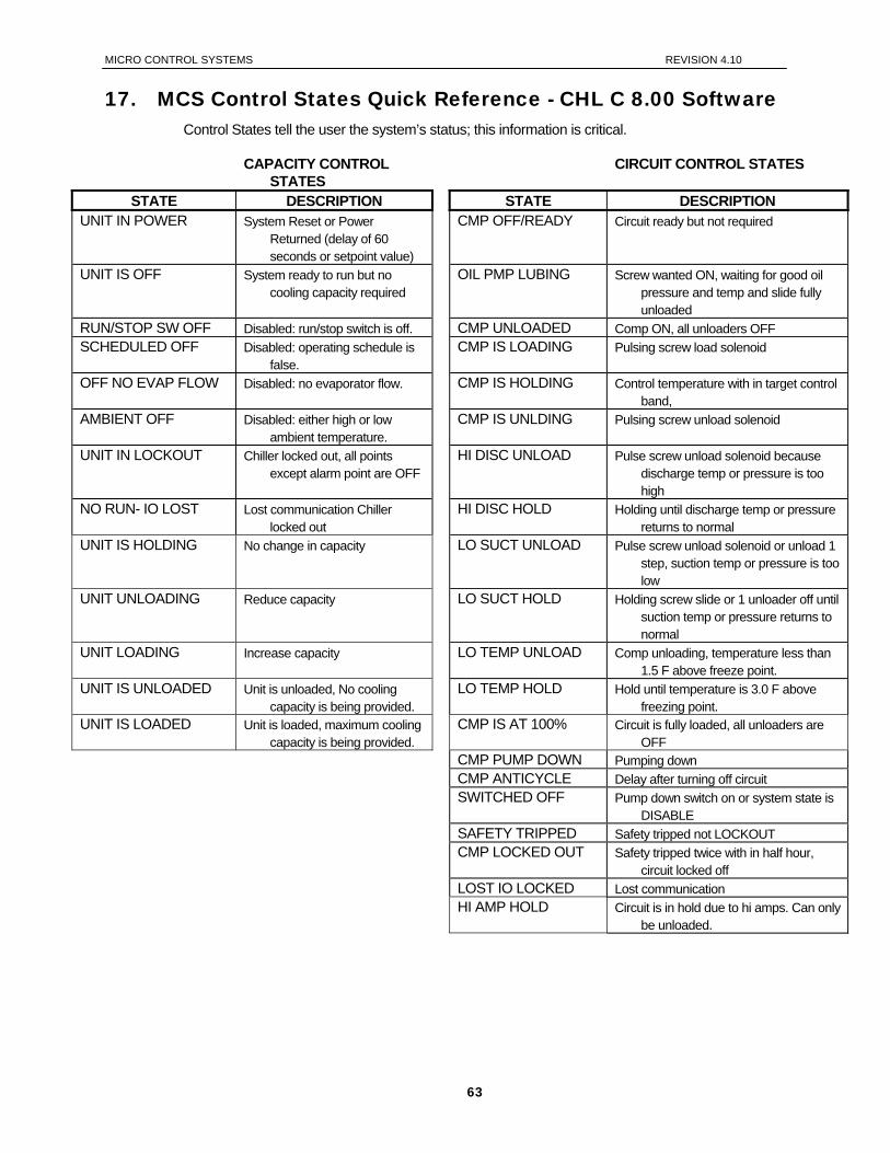
MICRO CONTROL SYSTEMS REVISION 4.10
17. MCS Control States Quick Reference - CHL C 8.00 Software Control States tell the user the system’s status; this information is critical.
CAPACITY CONTROL STATES
CIRCUIT CONTROL STATES
STATE DESCRIPTION STATE DESCRIPTION UNIT IN POWER System Reset or Power
Returned (delay of 60 seconds or setpoint value)
CMP OFF/READY Circuit ready but not required
UNIT IS OFF System ready to run but no cooling capacity required
OIL PMP LUBING Screw wanted ON, waiting for good oil pressure and temp and slide fully unloaded
RUN/STOP SW OFF Disabled: run/stop switch is off. CMP UNLOADED Comp ON, all unloaders OFF SCHEDULED OFF Disabled: operating schedule is
false. CMP IS LOADING Pulsing screw load solenoid
OFF NO EVAP FLOW Disabled: no evaporator flow. CMP IS HOLDING Control temperature with in target control band,
AMBIENT OFF Disabled: either high or low ambient temperature.
CMP IS UNLDING Pulsing screw unload solenoid
UNIT IN LOCKOUT Chiller locked out, all points except alarm point are OFF
HI DISC UNLOAD Pulse screw unload solenoid because discharge temp or pressure is too high
NO RUN- IO LOST Lost communication Chiller locked out
HI DISC HOLD Holding until discharge temp or pressure returns to normal
UNIT IS HOLDING No change in capacity LO SUCT UNLOAD Pulse screw unload solenoid or unload 1 step, suction temp or pressure is too low
UNIT UNLOADING Reduce capacity LO SUCT HOLD Holding screw slide or 1 unloader off until suction temp or pressure returns to normal
UNIT LOADING Increase capacity LO TEMP UNLOAD Comp unloading, temperature less than 1.5 F above freeze point.
UNIT IS UNLOADED Unit is unloaded, No cooling capacity is being provided.
LO TEMP HOLD Hold until temperature is 3.0 F above freezing point.
UNIT IS LOADED Unit is loaded, maximum cooling capacity is being provided.
CMP IS AT 100% Circuit is fully loaded, all unloaders are OFF
CMP PUMP DOWN Pumping down CMP ANTICYCLE Delay after turning off circuit SWITCHED OFF Pump down switch on or system state is
DISABLE SAFETY TRIPPED Safety tripped not LOCKOUT CMP LOCKED OUT Safety tripped twice with in half hour,
circuit locked off LOST IO LOCKED Lost communication HI AMP HOLD Circuit is in hold due to hi amps. Can only
be unloaded.
63
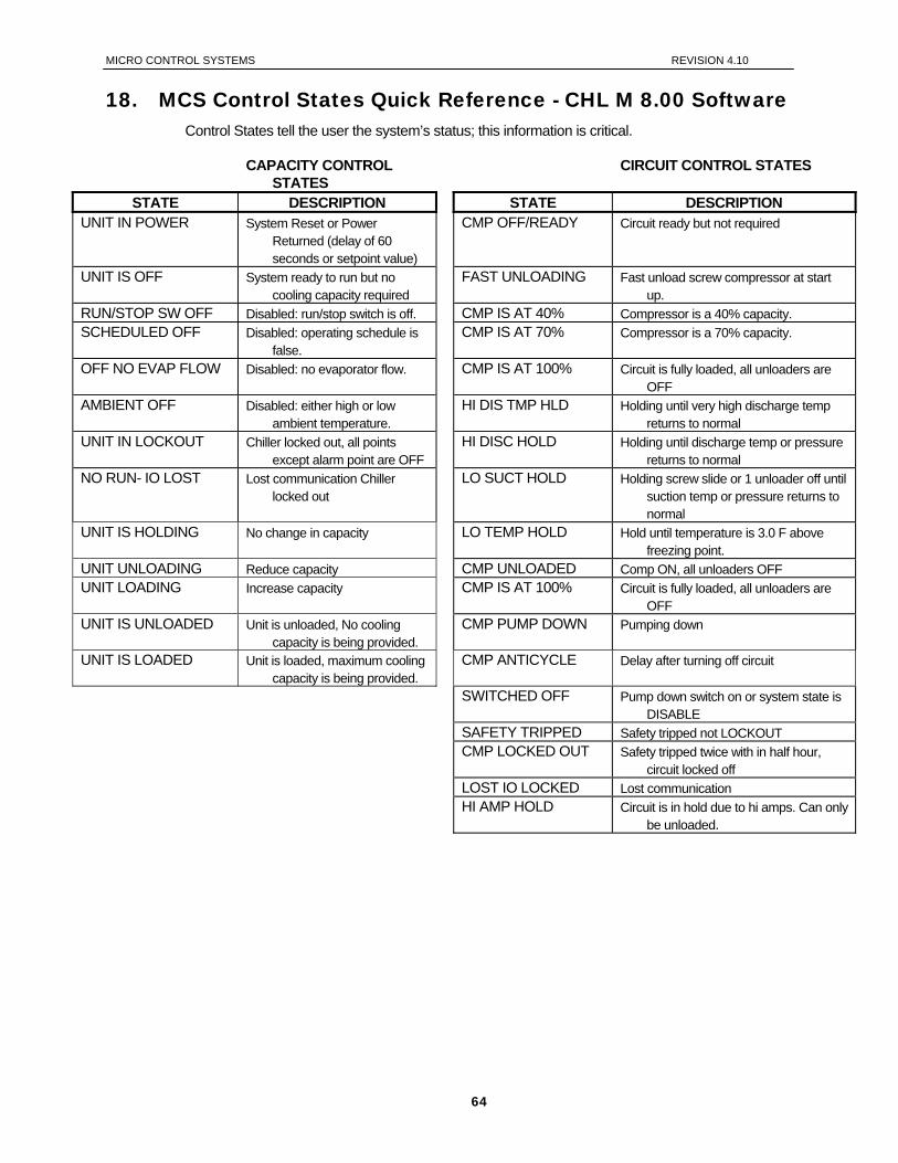
MICRO CONTROL SYSTEMS REVISION 4.10
18. MCS Control States Quick Reference - CHL M 8.00 Software Control States tell the user the system’s status; this information is critical.
CAPACITY CONTROL STATES
CIRCUIT CONTROL STATES
STATE DESCRIPTION STATE DESCRIPTION UNIT IN POWER System Reset or Power
Returned (delay of 60 seconds or setpoint value)
CMP OFF/READY Circuit ready but not required
UNIT IS OFF System ready to run but no cooling capacity required
FAST UNLOADING Fast unload screw compressor at start up.
RUN/STOP SW OFF Disabled: run/stop switch is off. CMP IS AT 40% Compressor is a 40% capacity. SCHEDULED OFF Disabled: operating schedule is
false. CMP IS AT 70% Compressor is a 70% capacity.
OFF NO EVAP FLOW Disabled: no evaporator flow. CMP IS AT 100% Circuit is fully loaded, all unloaders are OFF
AMBIENT OFF Disabled: either high or low ambient temperature.
HI DIS TMP HLD Holding until very high discharge temp returns to normal
UNIT IN LOCKOUT Chiller locked out, all points except alarm point are OFF
HI DISC HOLD Holding until discharge temp or pressure returns to normal
NO RUN- IO LOST Lost communication Chiller locked out
LO SUCT HOLD Holding screw slide or 1 unloader off until suction temp or pressure returns to normal
UNIT IS HOLDING No change in capacity LO TEMP HOLD Hold until temperature is 3.0 F above freezing point.
UNIT UNLOADING Reduce capacity CMP UNLOADED Comp ON, all unloaders OFF UNIT LOADING Increase capacity CMP IS AT 100% Circuit is fully loaded, all unloaders are
OFF UNIT IS UNLOADED Unit is unloaded, No cooling
capacity is being provided. CMP PUMP DOWN Pumping down
UNIT IS LOADED Unit is loaded, maximum cooling capacity is being provided.
CMP ANTICYCLE Delay after turning off circuit
SWITCHED OFF Pump down switch on or system state is DISABLE
SAFETY TRIPPED Safety tripped not LOCKOUT CMP LOCKED OUT Safety tripped twice with in half hour,
circuit locked off LOST IO LOCKED Lost communication HI AMP HOLD Circuit is in hold due to hi amps. Can only
be unloaded.
64
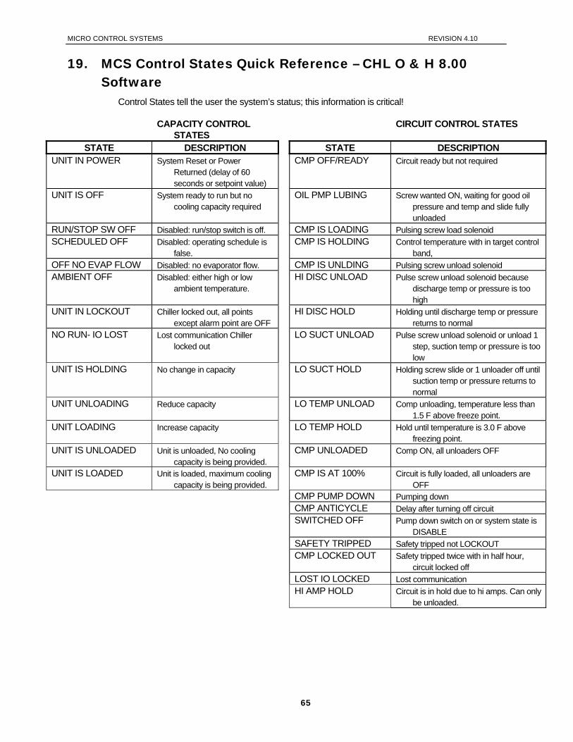
MICRO CONTROL SYSTEMS REVISION 4.10
19. MCS Control States Quick Reference – CHL O & H 8.00 Software
Control States tell the user the system’s status; this information is critical!
CAPACITY CONTROL STATES
CIRCUIT CONTROL STATES
STATE DESCRIPTION STATE DESCRIPTION UNIT IN POWER System Reset or Power
Returned (delay of 60 seconds or setpoint value)
CMP OFF/READY Circuit ready but not required
UNIT IS OFF System ready to run but no cooling capacity required
OIL PMP LUBING Screw wanted ON, waiting for good oil pressure and temp and slide fully unloaded
RUN/STOP SW OFF Disabled: run/stop switch is off. CMP IS LOADING Pulsing screw load solenoid SCHEDULED OFF Disabled: operating schedule is
false. CMP IS HOLDING Control temperature with in target control
band, OFF NO EVAP FLOW Disabled: no evaporator flow. CMP IS UNLDING Pulsing screw unload solenoid AMBIENT OFF Disabled: either high or low
ambient temperature. HI DISC UNLOAD Pulse screw unload solenoid because
discharge temp or pressure is too high
UNIT IN LOCKOUT Chiller locked out, all points except alarm point are OFF
HI DISC HOLD Holding until discharge temp or pressure returns to normal
NO RUN- IO LOST Lost communication Chiller locked out
LO SUCT UNLOAD Pulse screw unload solenoid or unload 1 step, suction temp or pressure is too low
UNIT IS HOLDING No change in capacity LO SUCT HOLD Holding screw slide or 1 unloader off until suction temp or pressure returns to normal
UNIT UNLOADING Reduce capacity LO TEMP UNLOAD Comp unloading, temperature less than 1.5 F above freeze point.
UNIT LOADING Increase capacity LO TEMP HOLD Hold until temperature is 3.0 F above freezing point.
UNIT IS UNLOADED Unit is unloaded, No cooling capacity is being provided.
CMP UNLOADED Comp ON, all unloaders OFF
UNIT IS LOADED Unit is loaded, maximum cooling capacity is being provided.
CMP IS AT 100% Circuit is fully loaded, all unloaders are OFF
CMP PUMP DOWN Pumping down CMP ANTICYCLE Delay after turning off circuit SWITCHED OFF Pump down switch on or system state is
DISABLE SAFETY TRIPPED Safety tripped not LOCKOUT CMP LOCKED OUT Safety tripped twice with in half hour,
circuit locked off LOST IO LOCKED Lost communication HI AMP HOLD Circuit is in hold due to hi amps. Can only
be unloaded.
65
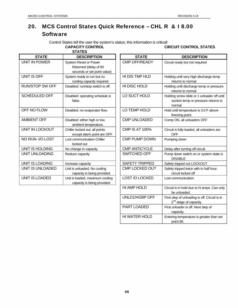
MICRO CONTROL SYSTEMS REVISION 4.10
20. MCS Control States Quick Reference – CHL R & I 8.00 Software
Control States tell the user the system’s status; this information is critical! CAPACITY CONTROL
STATES CIRCUIT CONTROL STATES
STATE DESCRIPTION STATE DESCRIPTION UNIT IN POWER System Reset or Power
Returned (delay of 60 seconds or set point value)
CMP OFF/READY Circuit ready but not required
UNIT IS OFF System ready to run but no cooling capacity required
HI DIS TMP HLD Holding until very high discharge temp returns to normal
RUN/STOP SW OFF Disabled: run/stop switch is off. HI DISC HOLD Holding until discharge temp or pressure returns to normal
SCHEDULED OFF Disabled: operating schedule is false.
LO SUCT HOLD Holding screw slide or 1 unloader off until suction temp or pressure returns to normal
OFF NO FLOW Disabled: no evaporator flow. LO TEMP HOLD Hold until temperature is 3.0 F above freezing point.
AMBIENT OFF Disabled: either high or low ambient temperature.
CMP UNLOADED Comp ON, all unloaders OFF
UNIT IN LOCKOUT Chiller locked out, all points except alarm point are OFF
CMP IS AT 100% Circuit is fully loaded, all unloaders are OFF
NO RUN- I/O LOST Lost communication Chiller locked out
CMP PUMP DOWN Pumping down
UNIT IS HOLDING No change in capacity CMP ANTICYCLE Delay after turning off circuit UNIT UNLOADING Reduce capacity SWITCHED OFF Pump down switch on or system state is
DISABLE UNIT IS LOADING Increase capacity SAFETY TRIPPED Safety tripped not LOCKOUT UNIT IS UNLOADED Unit is unloaded, No cooling
capacity is being provided. CMP LOCKED OUT Safety tripped twice with in half hour,
circuit locked off UNIT IS LOADED Unit is loaded, maximum cooling
capacity is being provided. LOST IO LOCKED Lost communication
HI AMP HOLD Circuit is in hold due to hi amps. Can only be unloaded.
UNLD1/HGBP OFF First step of unloading is off. Circuit is in 2nd stage of capacity.
PART LOADED First unloader is off. Next step of capacity.
HI WATER HOLD Entering temperature is greater than set point 86.
66
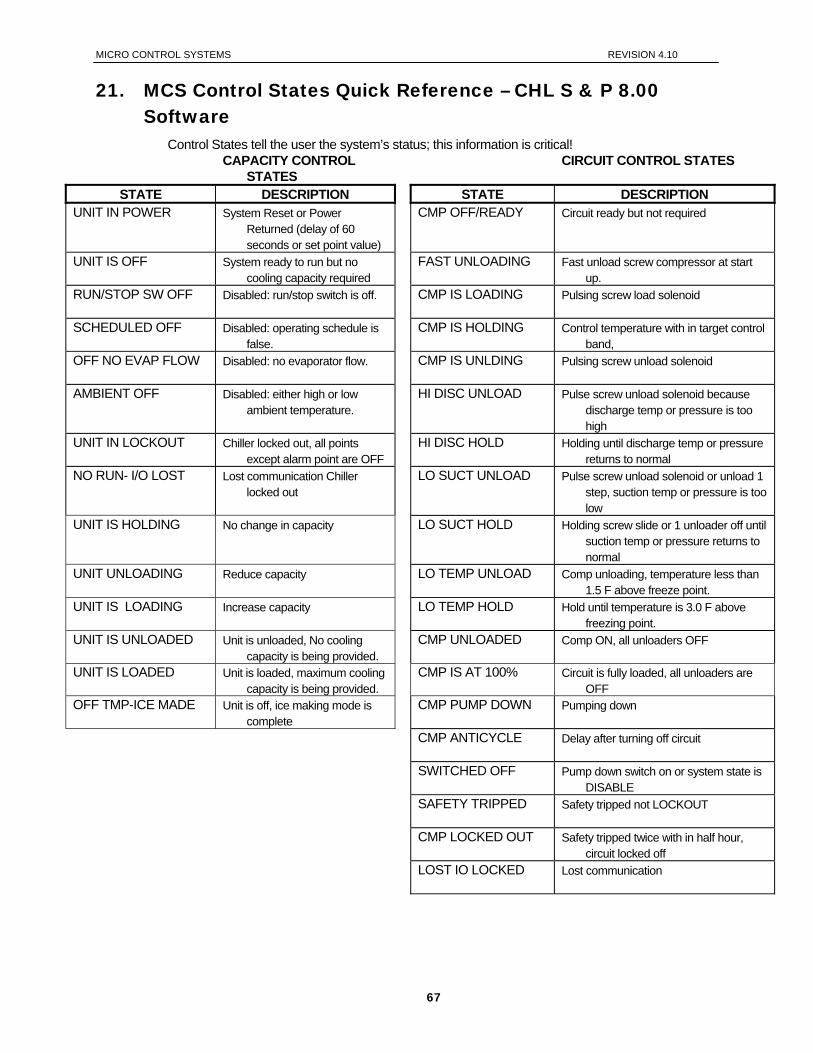
MICRO CONTROL SYSTEMS REVISION 4.10
21. MCS Control States Quick Reference – CHL S & P 8.00 Software
Control States tell the user the system’s status; this information is critical! CAPACITY CONTROL
STATES CIRCUIT CONTROL STATES
STATE DESCRIPTION STATE DESCRIPTION UNIT IN POWER System Reset or Power
Returned (delay of 60 seconds or set point value)
CMP OFF/READY Circuit ready but not required
UNIT IS OFF System ready to run but no cooling capacity required
FAST UNLOADING Fast unload screw compressor at start up.
RUN/STOP SW OFF Disabled: run/stop switch is off. CMP IS LOADING Pulsing screw load solenoid
SCHEDULED OFF Disabled: operating schedule is false.
CMP IS HOLDING Control temperature with in target control band,
OFF NO EVAP FLOW Disabled: no evaporator flow. CMP IS UNLDING Pulsing screw unload solenoid
AMBIENT OFF Disabled: either high or low ambient temperature.
HI DISC UNLOAD Pulse screw unload solenoid because discharge temp or pressure is too high
UNIT IN LOCKOUT Chiller locked out, all points except alarm point are OFF
HI DISC HOLD Holding until discharge temp or pressure returns to normal
NO RUN- I/O LOST Lost communication Chiller locked out
LO SUCT UNLOAD Pulse screw unload solenoid or unload 1 step, suction temp or pressure is too low
UNIT IS HOLDING No change in capacity LO SUCT HOLD Holding screw slide or 1 unloader off until suction temp or pressure returns to normal
UNIT UNLOADING Reduce capacity LO TEMP UNLOAD Comp unloading, temperature less than 1.5 F above freeze point.
UNIT IS LOADING Increase capacity LO TEMP HOLD Hold until temperature is 3.0 F above freezing point.
UNIT IS UNLOADED Unit is unloaded, No cooling capacity is being provided.
CMP UNLOADED Comp ON, all unloaders OFF
UNIT IS LOADED Unit is loaded, maximum cooling capacity is being provided.
CMP IS AT 100% Circuit is fully loaded, all unloaders are OFF
OFF TMP-ICE MADE Unit is off, ice making mode is complete
CMP PUMP DOWN Pumping down
CMP ANTICYCLE Delay after turning off circuit
SWITCHED OFF Pump down switch on or system state is DISABLE
SAFETY TRIPPED Safety tripped not LOCKOUT
CMP LOCKED OUT Safety tripped twice with in half hour, circuit locked off
LOST IO LOCKED Lost communication
67
MICRO CONTROL SYSTEMS REVISION 4.10
22. OEM Factory Checkout Procedure
22.1. Visual Check
120 VAC power wiring Jumper settings
Sensor input Address MCS communication termination EEPROM write protection
Sensor Wiring MCS-IO Communication Wiring LCD Connector (dot to mark on the board) Keypad Connector (dot to mark on the board) Chips
Master software and chip I/O software
RO Wiring
Ensure that the EMG stop is on (closed position) or run/stop input off so that the unit will not run after power applied to micro.
22.2. Mcs Power On (Compressor Power off)
MCS System on LCD on and valid display - “MCS Initialization” then default screen Communications light blinking if I/O units Get AUTHORIZED Check board version number: SERVICE DIAGNOSTICS/UNIT INFORMATION/HARDWARE
VERSION/ENTER (if change is required) Check sensor readings Manually bump (on then off) each point (take care your in control)
68
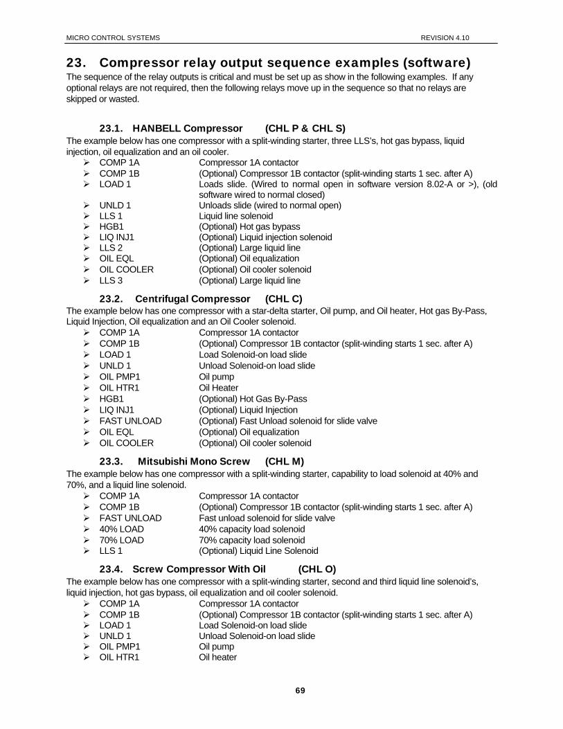
MICRO CONTROL SYSTEMS REVISION 4.10
23. Compressor relay output sequence examples (software) The sequence of the relay outputs is critical and must be set up as show in the following examples. If any optional relays are not required, then the following relays move up in the sequence so that no relays are skipped or wasted.
23.1. HANBELL Compressor (CHL P & CHL S) The example below has one compressor with a split-winding starter, three LLS’s, hot gas bypass, liquid injection, oil equalization and an oil cooler.
COMP 1A Compressor 1A contactor COMP 1B (Optional) Compressor 1B contactor (split-winding starts 1 sec. after A) LOAD 1 Loads slide. (Wired to normal open in software version 8.02-A or >), (old
software wired to normal closed) UNLD 1 Unloads slide (wired to normal open) LLS 1 Liquid line solenoid HGB1 (Optional) Hot gas bypass LIQ INJ1 (Optional) Liquid injection solenoid LLS 2 (Optional) Large liquid line OIL EQL (Optional) Oil equalization OIL COOLER (Optional) Oil cooler solenoid LLS 3 (Optional) Large liquid line
23.2. Centrifugal Compressor (CHL C) The example below has one compressor with a star-delta starter, Oil pump, and Oil heater, Hot gas By-Pass, Liquid Injection, Oil equalization and an Oil Cooler solenoid.
COMP 1A Compressor 1A contactor COMP 1B (Optional) Compressor 1B contactor (split-winding starts 1 sec. after A) LOAD 1 Load Solenoid-on load slide UNLD 1 Unload Solenoid-on load slide OIL PMP1 Oil pump OIL HTR1 Oil Heater HGB1 (Optional) Hot Gas By-Pass LIQ INJ1 (Optional) Liquid Injection FAST UNLOAD (Optional) Fast Unload solenoid for slide valve OIL EQL (Optional) Oil equalization OIL COOLER (Optional) Oil cooler solenoid
23.3. Mitsubishi Mono Screw (CHL M) The example below has one compressor with a split-winding starter, capability to load solenoid at 40% and 70%, and a liquid line solenoid.
COMP 1A Compressor 1A contactor COMP 1B (Optional) Compressor 1B contactor (split-winding starts 1 sec. after A) FAST UNLOAD Fast unload solenoid for slide valve 40% LOAD 40% capacity load solenoid 70% LOAD 70% capacity load solenoid LLS 1 (Optional) Liquid Line Solenoid
23.4. Screw Compressor With Oil (CHL O) The example below has one compressor with a split-winding starter, second and third liquid line solenoid’s, liquid injection, hot gas bypass, oil equalization and oil cooler solenoid.
COMP 1A Compressor 1A contactor COMP 1B (Optional) Compressor 1B contactor (split-winding starts 1 sec. after A) LOAD 1 Load Solenoid-on load slide UNLD 1 Unload Solenoid-on load slide OIL PMP1 Oil pump OIL HTR1 Oil heater
69
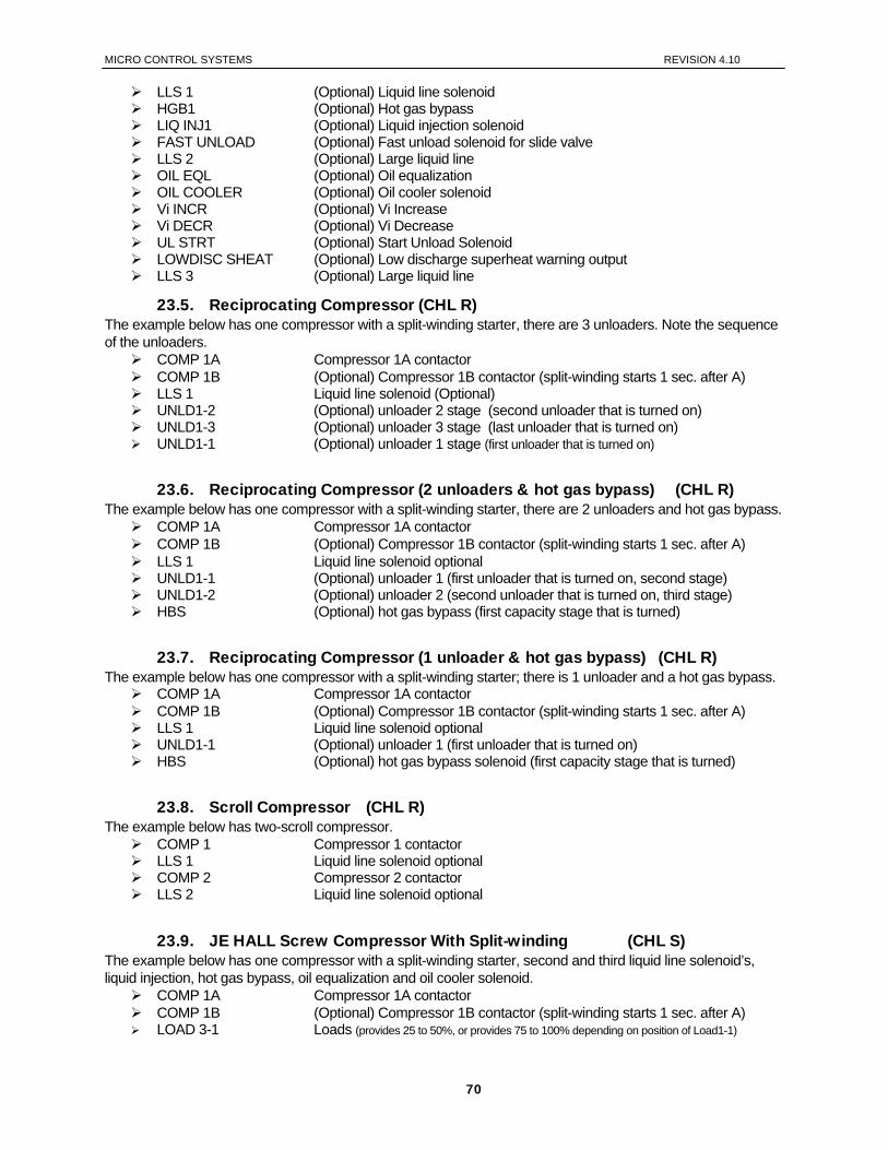
MICRO CONTROL SYSTEMS REVISION 4.10
LLS 1 (Optional) Liquid line solenoid HGB1 (Optional) Hot gas bypass LIQ INJ1 (Optional) Liquid injection solenoid FAST UNLOAD (Optional) Fast unload solenoid for slide valve LLS 2 (Optional) Large liquid line OIL EQL (Optional) Oil equalization OIL COOLER (Optional) Oil cooler solenoid Vi INCR (Optional) Vi Increase Vi DECR (Optional) Vi Decrease UL STRT (Optional) Start Unload Solenoid LOWDISC SHEAT (Optional) Low discharge superheat warning output LLS 3 (Optional) Large liquid line
23.5. Reciprocating Compressor (CHL R) The example below has one compressor with a split-winding starter, there are 3 unloaders. Note the sequence of the unloaders.
COMP 1A Compressor 1A contactor COMP 1B (Optional) Compressor 1B contactor (split-winding starts 1 sec. after A) LLS 1 Liquid line solenoid (Optional) UNLD1-2 (Optional) unloader 2 stage (second unloader that is turned on) UNLD1-3 (Optional) unloader 3 stage (last unloader that is turned on) UNLD1-1 (Optional) unloader 1 stage (first unloader that is turned on)
23.6. Reciprocating Compressor (2 unloaders & hot gas bypass) (CHL R) The example below has one compressor with a split-winding starter, there are 2 unloaders and hot gas bypass.
COMP 1A Compressor 1A contactor COMP 1B (Optional) Compressor 1B contactor (split-winding starts 1 sec. after A) LLS 1 Liquid line solenoid optional UNLD1-1 (Optional) unloader 1 (first unloader that is turned on, second stage) UNLD1-2 (Optional) unloader 2 (second unloader that is turned on, third stage) HBS (Optional) hot gas bypass (first capacity stage that is turned)
23.7. Reciprocating Compressor (1 unloader & hot gas bypass) (CHL R) The example below has one compressor with a split-winding starter; there is 1 unloader and a hot gas bypass.
COMP 1A Compressor 1A contactor COMP 1B (Optional) Compressor 1B contactor (split-winding starts 1 sec. after A) LLS 1 Liquid line solenoid optional UNLD1-1 (Optional) unloader 1 (first unloader that is turned on) HBS (Optional) hot gas bypass solenoid (first capacity stage that is turned)
23.8. Scroll Compressor (CHL R) The example below has two-scroll compressor.
COMP 1 Compressor 1 contactor LLS 1 Liquid line solenoid optional COMP 2 Compressor 2 contactor LLS 2 Liquid line solenoid optional
23.9. JE HALL Screw Compressor With Split-winding (CHL S) The example below has one compressor with a split-winding starter, second and third liquid line solenoid’s, liquid injection, hot gas bypass, oil equalization and oil cooler solenoid.
COMP 1A Compressor 1A contactor COMP 1B (Optional) Compressor 1B contactor (split-winding starts 1 sec. after A) LOAD 3-1 Loads (provides 25 to 50%, or provides 75 to 100% depending on position of Load1-1)
70
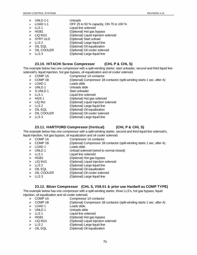
MICRO CONTROL SYSTEMS REVISION 4.10
UNLD 2-1 Unloads LOAD 1-1 OFF 25 to 50 % capacity, ON 75 to 100 % LLS 1 Liquid line solenoid HGB1 (Optional) Hot gas bypass LIQ INJ1 (Optional) Liquid injection solenoid STRT ULD (Optional) Start unload LLS 2 (Optional) Large liquid line OIL EQL (Optional) Oil equalization OIL COOLER (Optional) Oil cooler solenoid LLS 3 (Optional) Large liquid line
23.10. HITACHI Screw Compressor (CHL P & CHL S) The example below has one compressor with a split-winding starter, start unloader, second and third liquid line solenoid’s, liquid injection, hot gas bypass, oil equalization and oil cooler solenoid.
COMP 1A Compressor 1A contactor COMP 1B (Optional) Compressor 1B contactor (split-winding starts 1 sec. after A) LOAD 1 Loads slide UNLD 1 Unloads slide S UNLD 1 Start unloader LLS 1 Liquid line solenoid HGS 1 (Optional) Hot gas solenoid LIQ INJ (Optional) Liquid injection solenoid LLS 2 (Optional) Large liquid line OIL EQL (Optional) Oil equalization OIL COOLER (Optional) Oil cooler solenoid LLS 3 (Optional) Large liquid line
23.11. HARTFORD Compressor (Vertical) (CHL P & CHL S) The example below has one compressor with a split-winding starter, second and third liquid line solenoid’s, liquid injection, hot gas bypass, oil equalization and oil cooler solenoid.
COMP 1A Compressor 1A contactor COMP 1B (Optional) Compressor 1B contactor (split-winding starts 1 sec. after A) LOAD 1 Loads slide. UNLD 1 Unload solenoid (wired to normal closed) LLS 1 Liquid line solenoid HGB1 (Optional) Hot gas bypass LIQ INJ1 (Optional) Liquid injection solenoid LLS 2 (Optional) Large liquid line OIL EQL (Optional) Oil equalization OIL COOLER (Optional) Oil cooler solenoid LLS 3 (Optional) Large liquid line
23.12. Bitzer Compressor (CHL S, V08.01 & prior use Hanbell as COMP TYPE) The example below has one compressor with a split-winding starter, three LLS’s, hot gas bypass, liquid injection, oil equalization and oil cooler solenoid.
COMP 1A Compressor 1A contactor COMP 1B (Optional) Compressor 1B contactor (split-winding starts 1 sec. after A) LOAD 1 Loads slide. UNLD 1 Unloads slide LLS 1 Liquid line solenoid HGB1 (Optional) Hot gas bypass LIQ INJ1 (Optional) Liquid injection solenoid LLS 2 (Optional) Large liquid line OIL EQL (Optional) Oil equalization
71
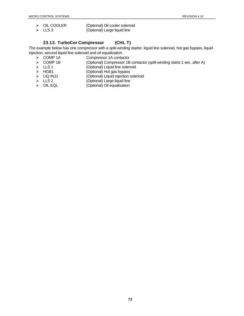
MICRO CONTROL SYSTEMS REVISION 4.10
OIL COOLER (Optional) Oil cooler solenoid LLS 3 (Optional) Large liquid line
23.13. TurboCor Compressor (CHL T) The example below has one compressor with a split-winding starter, liquid line solenoid, hot gas bypass, liquid injection, second liquid line solenoid and oil equalization.
COMP 1A Compressor 1A contactor COMP 1B (Optional) Compressor 1B contactor (split-winding starts 1 sec. after A) LLS 1 (Optional) Liquid line solenoid HGB1 (Optional) Hot gas bypass LIQ INJ1 (Optional) Liquid injection solenoid LLS 2 (Optional) Large liquid line OIL EQL (Optional) Oil equalization
72

MICRO CONTROL SYSTEMS REVISION 4.10
24. The Micro Control Center Keypad Display Quick Reference- STATUS KEYS
• No authorization is required in the DISPLAY STATUS section for viewing information. • Pressing a key selects the 1st two lines of data. Repressing the same key selects the next two lines, etc. • The ALARM STATUS displays all alarms and lockouts while LOCKOUT STATUS displays only active lockouts. • The “+” and “-“ keys may be used with alarm & lockout status to allow scrolling. • If one or more Micro Control Expansion units are connected to a Micro Control Center the data will be presented in a continuous
sequence. ADDITIONAL STATUS information shows names, total, run hours and starts for all RO’s. • SYSTEM PRESSURE displays information by circuit, SP suction pressure, DP discharge pressure, OPD oil pump differential, AMP or motor fault. • LOCKOUT STATUS for lockouts caused by either suction discharge oil or amps, the actual value at the time of the lockout of the associated sensor is displayed.
DISPLAY STATUS
7
COMP1 ON LLS 1 ON
ULS1-1 OFFCOMP2 ON
LLS2 ON ULS2-1 OFF
COMP3 ON LLS3 ON
ULS3-1 OFF
1 SP DP OPD AMP 69 185 116 43
1 SUCT SAT SHEAT51F 40F +11.4F
1 DISC SAT SHEAT158F 96F +61.8F
LVG. LIQ 44.8FRET. LIQ. 53.7F
AMB.TMP. 115.4FEMG STOP OFF
PMP DWW1 OFFPMP DWW2 OFF
PMP DWW3 OFFFLOW SW ON
COMP1 = 1015h STARTS=0000210
LLS1 = 1015h STARTS =000210
ULS1-1 = 0080h STARTS = 00210
8 APR 22 8:15:00 LOST IO SHUTDOWN
END OF LOCKOUTS ENTR VIEW OPTION
LVG.LIQ. 44.8F RET.LIQ. 53.7F
8
6
51
2
3
4
SYSTEM PRESSURE
COMPRESSOR STATUS
CONDENSOR STATUS
EVAPORATOR STATUS
ALARM STATUS
SYSTEM SENSORS
ADDITIONTAL STATUS INFO.
LOCKOUT STATUS
Chiller Configuration Example • Three reciprocating compressors • One unloader solenoid per compressor • One liquid line solenoid per compressor • Twelve condenser fans (6 RO’S) • Suction & discharge pressure per
compressor • Oil pressure per compressor • Leaving liquid temperature sensor • Return liquid temperature sensor • Ambient temperature sensor
1 APR 26 0:28:37 LOW SUCTION 2 APR 12 8:15:01 POWER RETURN
3 APR 12 8:11:11 POWER FAILED
PUMP ON FLOW SW ON
FAN 1&2 ON FAN 3&4 ON FAN 5&6 ON FAN 7&8 ON FAN 9&10 ON FAN 11&12 ON
Following info will be repeated for all active circuits)
73
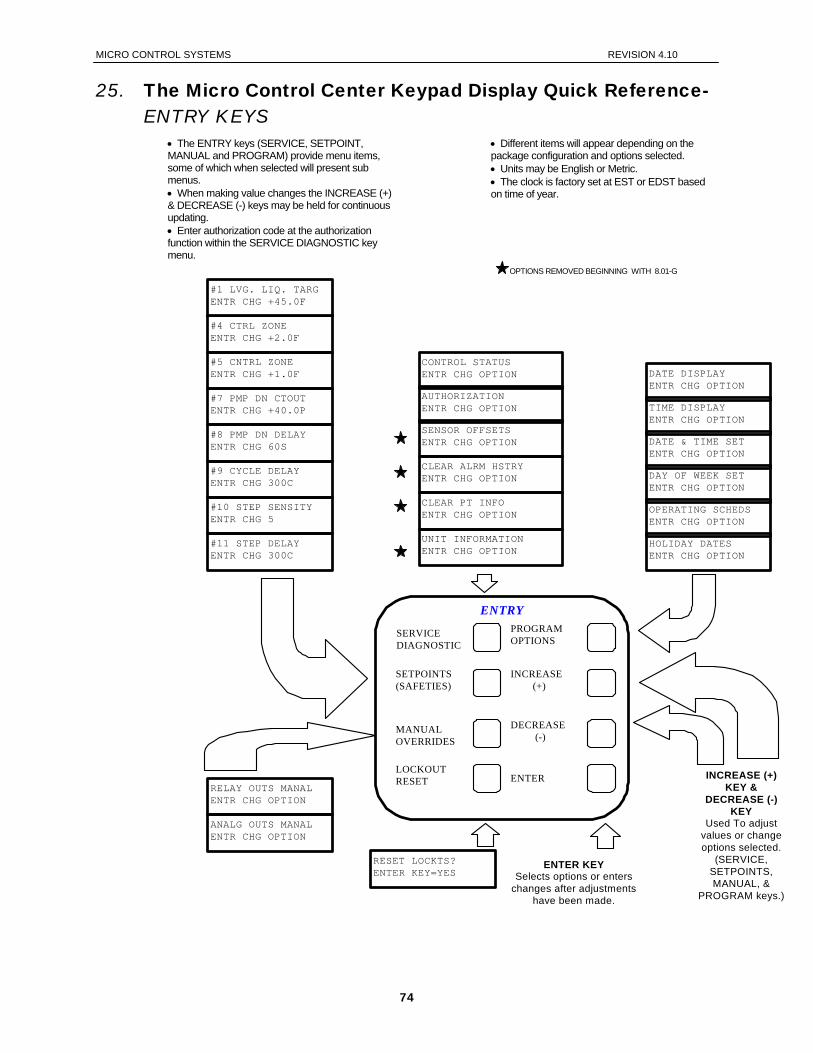
MICRO CONTROL SYSTEMS REVISION 4.10
25. The Micro Control Center Keypad Display Quick Reference-ENTRY KEYS
• The ENTRY keys (SERVICE, SETPOINT, MANUAL and PROGRAM) provide menu items, some of which when selected will present sub menus. • When making value changes the INCREASE (+) & DECREASE (-) keys may be held for continuous updating. • Enter authorization code at the authorization function within the SERVICE DIAGNOSTIC key menu.
• Different items will appear depending on the package configuration and options selected. • Units may be English or Metric. • The clock is factory set at EST or EDST based on time of year.
ENTRY
#1 LVG. LIQ. TARG ENTR CHG +45.0F
#4 CTRL ZONE ENTR CHG +2.0F
#5 CNTRL ZONE ENTR CHG +1.0F
#7 PMP DN CTOUT ENTR CHG +40.0P
#8 PMP DN DELAY ENTR CHG 60S
#9 CYCLE DELAY ENTR CHG 300C
#10 STEP SENSITY ENTR CHG 5
#11 STEP DELAY ENTR CHG 300C
AUTHORIZATION ENTR CHG OPTION
SENSOR OFFSETS ENTR CHG OPTION
CLEAR ALRM HSTRY ENTR CHG OPTION
CLEAR PT INFO ENTR CHG OPTION
UNIT INFORMATION ENTR CHG OPTION
CONTROL STATUS ENTR CHG OPTION
TIME DISPLAY ENTR CHG OPTION
DATE & TIME SET ENTR CHG OPTION
DAY OF WEEK SET ENTR CHG OPTION
OPERATING SCHEDS ENTR CHG OPTION
DATE DISPLAY ENTR CHG OPTION
RELAY OUTS MANAL ENTR CHG OPTION
ANALG OUTS MANAL ENTR CHG OPTION
RESET LOCKTS? ENTER KEY=YES ENTER KEY
Selects options or enters changes after adjustments
have been made.
INCREASE (+) KEY &
DECREASE (-) KEY
Used To adjust values or change options selected.
(SERVICE, SETPOINTS, MANUAL, &
PROGRAM keys.)
SERVICE DIAGNOSTIC
SETPOINTS (SAFETIES)
MANUAL OVERRIDES
LOCKOUT RESET
PROGRAM OPTIONS
INCREASE (+)
DECREASE (-)
ENTER
HOLIDAY DATES ENTR CHG OPTION
OPTIONS REMOVED BEGINNING WITH 8.01-G
74
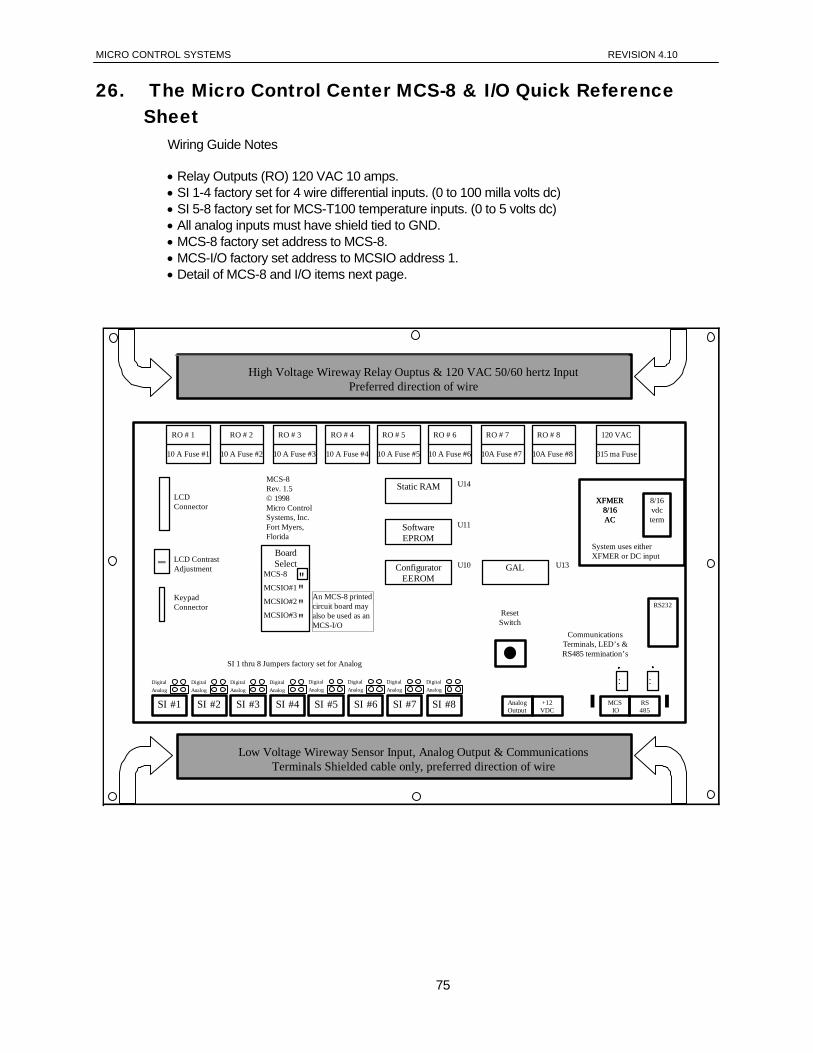
MICRO CONTROL SYSTEMS REVISION 4.10
26. The Micro Control Center MCS-8 & I/O Quick Reference Sheet
Wiring Guide Notes • Relay Outputs (RO) 120 VAC 10 amps. • SI 1-4 factory set for 4 wire differential inputs. (0 to 100 milla volts dc) • SI 5-8 factory set for MCS-T100 temperature inputs. (0 to 5 volts dc) • All analog inputs must have shield tied to GND. • MCS-8 factory set address to MCS-8. • MCS-I/O factory set address to MCSIO address 1. • Detail of MCS-8 and I/O items next page.
RO # 1 RO # 2 RO # 3 RO # 4 RO # 5 RO # 6 RO # 7 RO # 8 120 VAC
KeypadConnector
LCD ContrastAdjustment
LCDConnector
U14
U11
U10
10 A Fuse #3 10 A Fuse #410 A Fuse #1 10 A Fuse #2 10A Fuse #7 10A Fuse #810 A Fuse #5 10 A Fuse #6 315 ma Fuse
MCS-8Rev. 1.5© 1998Micro ControlSystems, Inc.Fort Myers,Florida
BoardSelect
MCS-8
MCSIO#1
MCSIO#2
MCSIO#3
""""
Static RAM
SoftwareEPROM
ConfiguratorEEROM
XFMER8/16AC
8/16vdcterm
System uses eitherXFMER or DC input
XFMER8/16AC
SI #1
ResetSwitch
+12VDC
AnalogOutput
RS485
MCS IO
CommunicationsTerminals, LED’s &RS485 termination’s
RS232
High Voltage Wireway Relay Ouptus & 120 VAC 50/60 hertz InputPreferred direction of wire
Low Voltage Wireway Sensor Input, Analog Output & CommunicationsTerminals Shielded cable only, preferred direction of wire
: :
SI 1 thru 8 Jumpers factory set for Analog
GAL U13
AnalogDigital
SI #2AnalogDigital
SI #3AnalogDigital
SI #4AnalogDigital
SI #5AnalogDigital
SI #6AnalogDigital
SI #7AnalogDigital
SI #8AnalogDigital
An MCS-8 printedcircuit board mayalso be used as anMCS-I/O
75
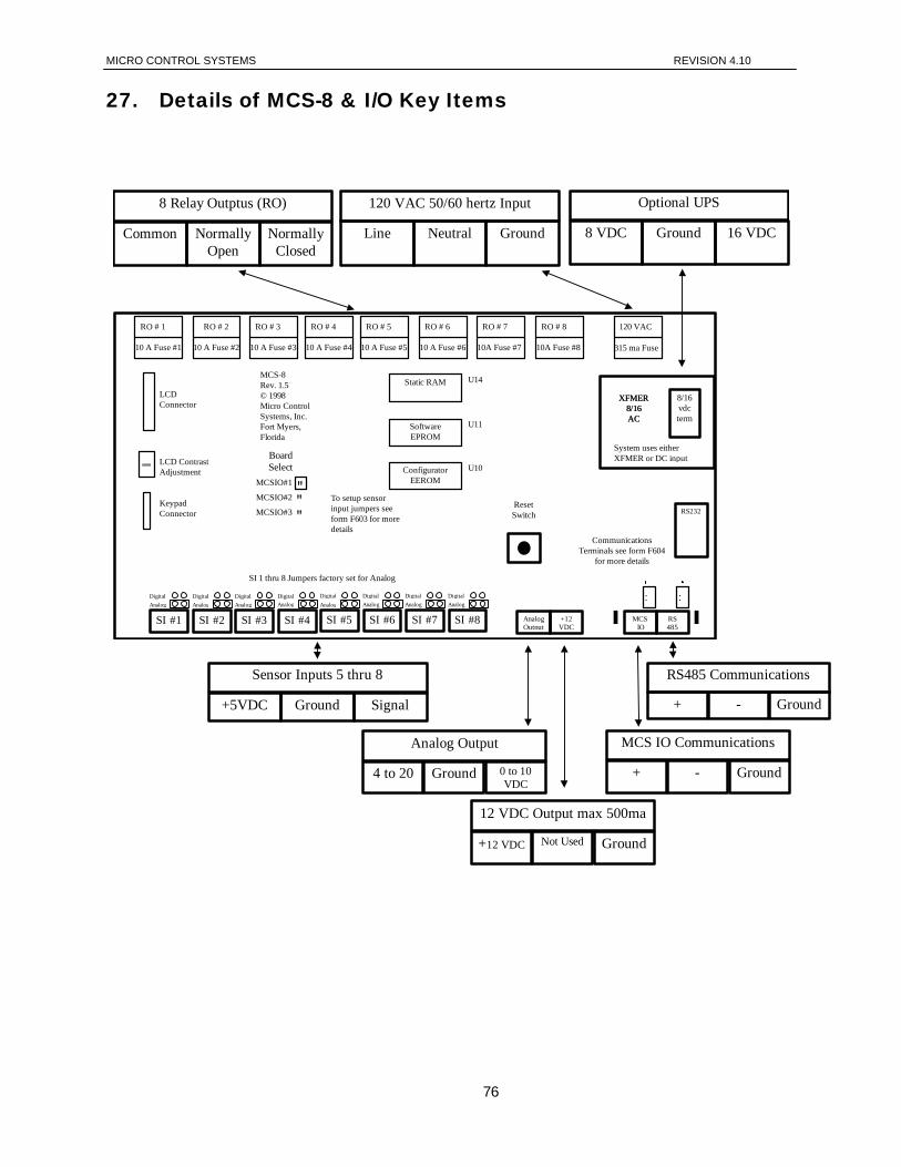
MICRO CONTROL SYSTEMS REVISION 4.10
27. Details of MCS-8 & I/O Key Items
�
RO # 1 RO # 2 RO # 3 RO # 4 RO # 5 RO # 6 RO # 7 RO # 8 120 VAC
KeypadConnector
LCD ContrastAdjustment
LCDConnector
U14
U11
U10
10 A Fuse #3 10 A Fuse #410 A Fuse #1 10 A Fuse #2 10A Fuse #7 10A Fuse #810 A Fuse #5 10 A Fuse #6 315 ma Fuse
MCS-8Rev. 1.5© 1998Micro ControlSystems, Inc.Fort Myers,Florida
BoardSelect
MCSIO#1
MCSIO#2
MCSIO#3
"""
Static RAM
SoftwareEPROM
ConfiguratorEEROM
XFMER8/16AC
8/16vdcterm
System uses eitherXFMER or DC input
XFMER8/16AC
ResetSwitch
+12VDC
AnalogOutput
RS485
MCS IO
CommunicationsTerminals see form F604
for more details
RS232
8 Relay Outptus (RO)
Common NormallyOpen
NormallyClosed
120 VAC 50/60 hertz Input
Line Neutral Ground
Optional UPS
8 VDC Ground 16 VDC
Sensor Inputs 5 thru 8
+5VDC Ground Signal
RS485 Communications
+ - Ground
MCS IO Communications
+ - Ground
12 VDC Output max 500ma
+12 VDC Not Used Ground
Analog Output
4 to 20 Ground 0 to 10VDC
: :
To setup sensorinput jumpers seeform F603 for moredetails
SI #1AnalogDigital
SI #2AnalogDigital
SI #3AnalogDigital
SI #4Analog
Digital
SI #5
Digital
SI #6AnalogDigital
SI #7AnalogDigital
SI #8AnalogDigital
SI 1 thru 8 Jumpers factory set for Analog
Analog
76
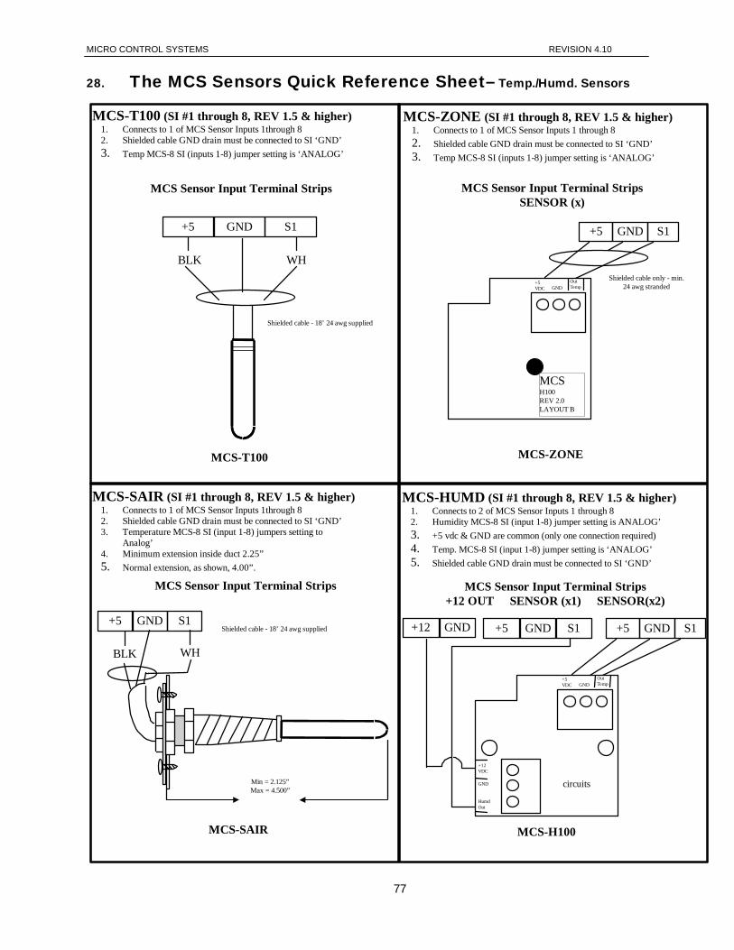
MICRO CONTROL SYSTEMS REVISION 4.10
28. The MCS Sensors Quick Reference Sheet– Temp./Humd. Sensors
MCS-T100 (SI #1 through 8, REV 1.5 & higher)1. Connects to 1 of MCS Sensor Inputs 1through 82. Shielded cable GND drain must be connected to SI ‘GND’3. Temp MCS-8 SI (inputs 1-8) jumper setting is ‘ANALOG’
MCS Sensor Input Terminal Strips
BLK WH
+5 GND S1
MCS-T100
Shielded cable - 18’ 24 awg supplied
MCS-SAIR (SI #1 through 8, REV 1.5 & higher)1. Connects to 1 of MCS Sensor Inputs 1through 82. Shielded cable GND drain must be connected to SI ‘GND’3. Temperature MCS-8 SI (input 1-8) jumpers setting to
Analog’4. Minimum extension inside duct 2.25”5. Normal extension, as shown, 4.00”.
MCS Sensor Input Terminal Strips
BLK WH
+5 GND S1Shielded cable - 18’ 24 awg supplied
Min = 2.125”Max = 4.500”
MCS-SAIR
MCS-ZONE (SI #1 through 8, REV 1.5 & higher)1. Connects to 1 of MCS Sensor Inputs 1 through 82. Shielded cable GND drain must be connected to SI ‘GND’3. Temp MCS-8 SI (inputs 1-8) jumper setting is ‘ANALOG’
MCS Sensor Input Terminal StripsSENSOR (x)
MCS-ZONE
MCS-HUMD (SI #1 through 8, REV 1.5 & higher)1. Connects to 2 of MCS Sensor Inputs 1 through 82. Humidity MCS-8 SI (input 1-8) jumper setting is ANALOG’3. +5 vdc & GND are common (only one connection required)4. Temp. MCS-8 SI (input 1-8) jumper setting is ‘ANALOG’5. Shielded cable GND drain must be connected to SI ‘GND’
MCS Sensor Input Terminal Strips+12 OUT SENSOR (x1) SENSOR(x2)
+12 GND +5 GND S1 +5 GND S1
+5VDC GND
OutTemp
+12VDC
GND
HumdOut
circuits
MCS-H100
+5 GND S1
+5VDC GND
OutTemp
Shielded cable only - min.24 awg stranded
MCSH100REV 2.0LAYOUT B
77
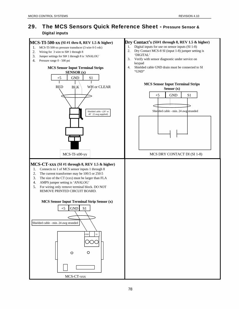
MICRO CONTROL SYSTEMS REVISION 4.10
29. The MCS Sensors Quick Reference Sheet - Pressure Sensor & Digital inputs
MCS-TI-500-xx (SI #1 thru 8, REV 1.5 & higher)1. MCS-TI-500-xx pressure transducer (3 wire 0-5 vdc)2. Wiring for 3 wire to SI# 1 through 83. Jumper settings for SI# 1 through 8 is ‘ANALOG’4. Pressure range 0 - 500 psi
MCS Sensor Input Terminal StripsSENSOR (x)
RED WH or CLEAR
+5 GND S1
Shielded cable - (20’ or40’ 22 awg supplied)
BLK
MCS-TI-x00-yy
Dry Contact’s (SI#1 through 8, REV 1.5 & higher)1. Digital inputs for use on sensor inputs (SI 1-8)2. Dry Contact MCS-8 SI (input 1-8) jumper setting is
‘DIGITAL’3. Verify with sensor diagnostic under service on
keypad4. Shielded cable GND drain must be connected to SI
“GND”
+5 GND S1
MCS Sensor Input Terminal StripsSensor (x)
Shielded cable - min. 24 awg stranded
MCS DRY CONTACT DI (SI 1-8)
MCS-CT-xxx (SI #1 through 8, REV 1.5 & higher)1. Connects to 1 of MCS sensor inputs 1 through 82. The current transformer may be 100:5 or 250:53. The size of the CT (xxx) must be larger than FLA4. AMPS jumper setting is ‘ANALOG’5. For wiring only remove terminal block. DO NOT
REMOVE PRINTED CIRCUIT BOARD.
+5 GND S1
MCS Sensor Input Terminal Strip Sensor (x)
Shielded cable - min. 24 awg stranded
MCS-CT-xxx
GND S1
78
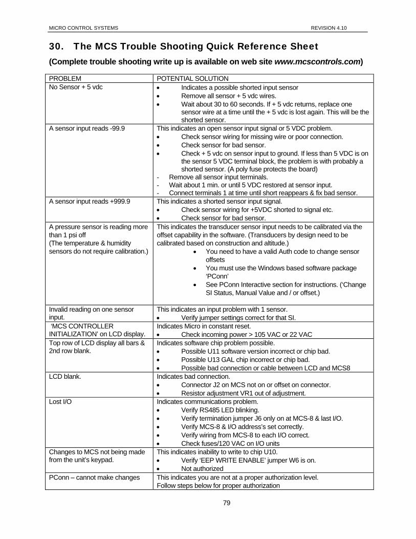
MICRO CONTROL SYSTEMS REVISION 4.10
30. The MCS Trouble Shooting Quick Reference Sheet (Complete trouble shooting write up is available on web site www.mcscontrols.com)
PROBLEM POTENTIAL SOLUTION No Sensor + 5 vdc • Indicates a possible shorted input sensor
• Remove all sensor + 5 vdc wires. • Wait about 30 to 60 seconds. If + 5 vdc returns, replace one
sensor wire at a time until the + 5 vdc is lost again. This will be the shorted sensor.
A sensor input reads -99.9 This indicates an open sensor input signal or 5 VDC problem. • Check sensor wiring for missing wire or poor connection. • Check sensor for bad sensor. • Check + 5 vdc on sensor input to ground. If less than 5 VDC is on
the sensor 5 VDC terminal block, the problem is with probably a shorted sensor. (A poly fuse protects the board)
- Remove all sensor input terminals. - Wait about 1 min. or until 5 VDC restored at sensor input. - Connect terminals 1 at time until short reappears & fix bad sensor.
A sensor input reads +999.9 This indicates a shorted sensor input signal. • Check sensor wiring for +5VDC shorted to signal etc. • Check sensor for bad sensor.
A pressure sensor is reading more than 1 psi off (The temperature & humidity sensors do not require calibration.)
This indicates the transducer sensor input needs to be calibrated via the offset capability in the software. (Transducers by design need to be calibrated based on construction and altitude.)
• You need to have a valid Auth code to change sensor offsets
• You must use the Windows based software package ‘PConn’
• See PConn Interactive section for instructions. (‘Change SI Status, Manual Value and / or offset.)
Invalid reading on one sensor input.
This indicates an input problem with 1 sensor. • Verify jumper settings correct for that SI.
‘MCS CONTROLLER INITIALIZATION’ on LCD display.
Indicates Micro in constant reset. • Check incoming power > 105 VAC or 22 VAC
Top row of LCD display all bars & 2nd row blank.
Indicates software chip problem possible. • Possible U11 software version incorrect or chip bad. • Possible U13 GAL chip incorrect or chip bad. • Possible bad connection or cable between LCD and MCS8
LCD blank. Indicates bad connection. • Connector J2 on MCS not on or offset on connector. • Resistor adjustment VR1 out of adjustment.
Lost I/O Indicates communications problem. • Verify RS485 LED blinking. • Verify termination jumper J6 only on at MCS-8 & last I/O. • Verify MCS-8 & I/O address’s set correctly. • Verify wiring from MCS-8 to each I/O correct. • Check fuses/120 VAC on I/O units
Changes to MCS not being made from the unit’s keypad.
This indicates inability to write to chip U10. • Verify ‘EEP WRITE ENABLE’ jumper W6 is on. • Not authorized
PConn – cannot make changes This indicates you are not at a proper authorization level. Follow steps below for proper authorization
79
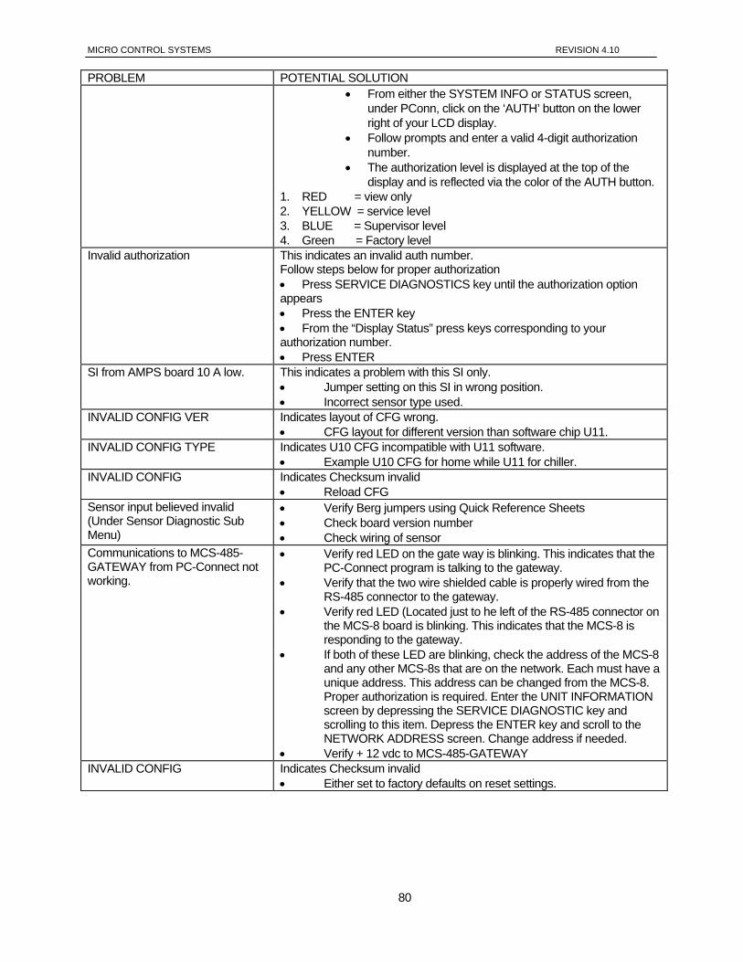
MICRO CONTROL SYSTEMS REVISION 4.10
PROBLEM POTENTIAL SOLUTION • From either the SYSTEM INFO or STATUS screen,
under PConn, click on the ‘AUTH’ button on the lower right of your LCD display.
• Follow prompts and enter a valid 4-digit authorization number.
• The authorization level is displayed at the top of the display and is reflected via the color of the AUTH button.
1. RED = view only 2. YELLOW = service level 3. BLUE = Supervisor level 4. Green = Factory level
Invalid authorization This indicates an invalid auth number. Follow steps below for proper authorization • Press SERVICE DIAGNOSTICS key until the authorization option appears • Press the ENTER key • From the “Display Status” press keys corresponding to your authorization number. • Press ENTER
SI from AMPS board 10 A low. This indicates a problem with this SI only. • Jumper setting on this SI in wrong position. • Incorrect sensor type used.
INVALID CONFIG VER Indicates layout of CFG wrong. • CFG layout for different version than software chip U11.
INVALID CONFIG TYPE Indicates U10 CFG incompatible with U11 software. • Example U10 CFG for home while U11 for chiller.
INVALID CONFIG Indicates Checksum invalid • Reload CFG
Sensor input believed invalid (Under Sensor Diagnostic Sub Menu)
• Verify Berg jumpers using Quick Reference Sheets • Check board version number • Check wiring of sensor
Communications to MCS-485-GATEWAY from PC-Connect not working.
• Verify red LED on the gate way is blinking. This indicates that the PC-Connect program is talking to the gateway.
• Verify that the two wire shielded cable is properly wired from the RS-485 connector to the gateway.
• Verify red LED (Located just to he left of the RS-485 connector on the MCS-8 board is blinking. This indicates that the MCS-8 is responding to the gateway.
• If both of these LED are blinking, check the address of the MCS-8 and any other MCS-8s that are on the network. Each must have a unique address. This address can be changed from the MCS-8. Proper authorization is required. Enter the UNIT INFORMATION screen by depressing the SERVICE DIAGNOSTIC key and scrolling to this item. Depress the ENTER key and scroll to the NETWORK ADDRESS screen. Change address if needed.
• Verify + 12 vdc to MCS-485-GATEWAY INVALID CONFIG Indicates Checksum invalid
• Either set to factory defaults on reset settings.
80

MICRO CONTROL SYSTEMS REVISION 4.10
--- NOTE ---
ALL SENSOR INPUTS SHOULD BE SHIELDED CABLE WITH SHIELD TIED TO GROUND ON MCS-8 SENSOR INPUT GROUND
TERMINAL
81