mcp8024 tqfp bldc motor driver evaluation board user's guide
TRANSCRIPT
2013 Microchip Technology Inc. DS50002233A
MCP8024 TQFPBLDC Motor Driver
Evaluation BoardUser’s Guide
DS50002233A-page 2 2013 Microchip Technology Inc.
Information contained in this publication regarding deviceapplications and the like is provided only for your convenienceand may be superseded by updates. It is your responsibility toensure that your application meets with your specifications.MICROCHIP MAKES NO REPRESENTATIONS ORWARRANTIES OF ANY KIND WHETHER EXPRESS ORIMPLIED, WRITTEN OR ORAL, STATUTORY OROTHERWISE, RELATED TO THE INFORMATION,INCLUDING BUT NOT LIMITED TO ITS CONDITION,QUALITY, PERFORMANCE, MERCHANTABILITY ORFITNESS FOR PURPOSE. Microchip disclaims all liabilityarising from this information and its use. Use of Microchipdevices in life support and/or safety applications is entirely atthe buyer’s risk, and the buyer agrees to defend, indemnify andhold harmless Microchip from any and all damages, claims,suits, or expenses resulting from such use. No licenses areconveyed, implicitly or otherwise, under any Microchipintellectual property rights.
Note the following details of the code protection feature on Microchip devices:• Microchip products meet the specification contained in their particular Microchip Data Sheet.
• Microchip believes that its family of products is one of the most secure families of its kind on the market today, when used in the intended manner and under normal conditions.
• There are dishonest and possibly illegal methods used to breach the code protection feature. All of these methods, to our knowledge, require using the Microchip products in a manner outside the operating specifications contained in Microchip’s Data Sheets. Most likely, the person doing so is engaged in theft of intellectual property.
• Microchip is willing to work with the customer who is concerned about the integrity of their code.
• Neither Microchip nor any other semiconductor manufacturer can guarantee the security of their code. Code protection does not mean that we are guaranteeing the product as “unbreakable.”
Code protection is constantly evolving. We at Microchip are committed to continuously improving the code protection features of ourproducts. Attempts to break Microchip’s code protection feature may be a violation of the Digital Millennium Copyright Act. If such actsallow unauthorized access to your software or other copyrighted work, you may have a right to sue for relief under that Act.
Microchip received ISO/TS-16949:2009 certification for its worldwide headquarters, design and wafer fabrication facilities in Chandler and Tempe, Arizona; Gresham, Oregon and design centers in California and India. The Company’s quality system processes and procedures are for its PIC® MCUs and dsPIC® DSCs, KEELOQ® code hopping devices, Serial EEPROMs, microperipherals, nonvolatile memory and analog products. In addition, Microchip’s quality system for the design and manufacture of development systems is ISO 9001:2000 certified.
QUALITY MANAGEMENT SYSTEM CERTIFIED BY DNV
== ISO/TS 16949 ==
Trademarks
The Microchip name and logo, the Microchip logo, dsPIC, FlashFlex, KEELOQ, KEELOQ logo, MPLAB, PIC, PICmicro, PICSTART, PIC32 logo, rfPIC, SST, SST Logo, SuperFlash and UNI/O are registered trademarks of Microchip Technology Incorporated in the U.S.A. and other countries.
FilterLab, Hampshire, HI-TECH C, Linear Active Thermistor, MTP, SEEVAL and The Embedded Control Solutions Company are registered trademarks of Microchip Technology Incorporated in the U.S.A.
Silicon Storage Technology is a registered trademark of Microchip Technology Inc. in other countries.
Analog-for-the-Digital Age, Application Maestro, BodyCom, chipKIT, chipKIT logo, CodeGuard, dsPICDEM, dsPICDEM.net, dsPICworks, dsSPEAK, ECAN, ECONOMONITOR, FanSense, HI-TIDE, In-Circuit Serial Programming, ICSP, Mindi, MiWi, MPASM, MPF, MPLAB Certified logo, MPLIB, MPLINK, mTouch, Omniscient Code Generation, PICC, PICC-18, PICDEM, PICDEM.net, PICkit, PICtail, REAL ICE, rfLAB, Select Mode, SQI, Serial Quad I/O, Total Endurance, TSHARC, UniWinDriver, WiperLock, ZENA and Z-Scale are trademarks of Microchip Technology Incorporated in the U.S.A. and other countries.
SQTP is a service mark of Microchip Technology Incorporated in the U.S.A.
GestIC and ULPP are registered trademarks of Microchip Technology Germany II GmbH & Co. KG, a subsidiary of Microchip Technology Inc., in other countries.
All other trademarks mentioned herein are property of their respective companies.
© 2013, Microchip Technology Incorporated, Printed in the U.S.A., All Rights Reserved.
Printed on recycled paper.
ISBN: 9781620777800
MCP8024 TQFP BLDC MOTOR DRIVEREVALUATION BOARD USER’S GUIDE
Table of Contents
Preface ........................................................................................................................... 7Introduction............................................................................................................ 7Document Layout .................................................................................................. 7Conventions Used in this Guide ............................................................................ 8Recommended Reading........................................................................................ 9The Microchip Web Site ........................................................................................ 9Development Systems Customer Change Notification Service .......................... 10Customer Support ............................................................................................... 10Document Revision History ................................................................................. 10
Chapter 1. Product Overview1.1 Introduction ................................................................................................... 111.2 What is the MCP8024 TQFP BLDC Motor Driver Evaluation Board? .......... 121.3 What the MCP8024 TQFP BLDC Motor Driver Evaluation Board
Kit Includes ............................................................................................. 12Chapter 2. Installation and Operation
2.1 Introduction ................................................................................................... 132.2 Features ....................................................................................................... 132.3 Getting Started ............................................................................................. 14
2.3.1 Connections .............................................................................................. 142.3.2 Operating a Motor ..................................................................................... 172.3.3 Indicator LEDs ........................................................................................... 182.3.4 Test Points ................................................................................................ 182.3.5 User Program Data Logging and Communications ................................... 192.3.6 Re-Programming the dsPIC DSC PIM ...................................................... 192.3.7 Configuring the MCP8024 ......................................................................... 192.3.8 MCP8024 Status ....................................................................................... 21
Appendix A. Schematic and LayoutsA.1 Introduction .................................................................................................. 23A.2 Board – Schematic ....................................................................................... 24A.3 Board – Top Silk Layer ................................................................................ 25A.4 Board – Top Metal Layer ............................................................................. 26A.5 Board – Mid1 Metal Layer ............................................................................ 27A.6 Board – Mid2 Metal Layer ............................................................................ 28A.7 Board – Bottom Metal Layer ........................................................................ 29
Appendix B. Bill of Materials (BOM)
2013 Microchip Technology Inc. DS50002233A-page 3

MCP8024 TQFP BLDC Motor Driver Evaluation Board User’s Guide
Appendix C. SoftwareC.1 Selected Software Constants and Definitions .............................................. 35C.2 dsPIC33FJ32MC204 PIM Port Usage ......................................................... 36C.3 MPLAB X IDE Compiler Startup .................................................................. 37C.4 MPLAB X IDE and PICkit 3 Programmer Exercise ...................................... 37
Worldwide Sales and Service .....................................................................................40
DS50002233A-page 4 2013 Microchip Technology Inc.

Object of Declaration: MCP8024 TQFP BLDC Motor Driver Evaluation Board
2013 Microchip Technology Inc. DS50002233A-page 5
MCP8024 TQFP BLDC Motor Driver Evaluation Board User’s Guide
NOTES:
DS50002233A-page 6 2013 Microchip Technology Inc.

MCP8024 TQFP BLDC MOTOR DRIVER
EVALUATION BOARD USER’S GUIDEPreface
INTRODUCTIONThis chapter contains general information that will be useful to know before using the MCP8024 TQFP BLDC Motor Driver Evaluation Board. Items discussed in this chapter include:• Document Layout• Conventions Used in this Guide• Recommended Reading• The Microchip Web Site• Customer Support• Document Revision History
DOCUMENT LAYOUTThis document describes how to use the MCP8024 TQFP BLDC Motor Driver Evalua-tion Board. The manual layout is as follows:• Chapter 1. “Product Overview” – Important information about the MCP8024
TQFP BLDC Motor Driver Evaluation Board.• Chapter 2. “Installation and Operation” – Includes instructions on how to get
started with this user’s guide and a description of the user’s guide.• Appendix A. “Schematic and Layouts” – Shows the schematic and layout
diagrams for the MCP8024 TQFP BLDC Motor Driver Evaluation Board.• Appendix B. “Bill of Materials (BOM)” – Lists the parts used to build the
MCP8024 TQFP BLDC Motor Driver Evaluation Board.• Appendix C. “Software” – Provides information about the application firmware
and where the source code can be found.
NOTICE TO CUSTOMERS
All documentation becomes dated, and this manual is no exception. Microchip tools and documentation are constantly evolving to meet customer needs, so some actual dialogs and/or tool descriptions may differ from those in this document. Please refer to our web site (www.microchip.com) to obtain the latest documentation available.
Documents are identified with a “DS” number. This number is located on the bottom of each page, in front of the page number. The numbering convention for the DS number is “DSXXXXXA”, where “XXXXX” is the document number and “A” is the revision level of the document.
For the most up-to-date information on development tools, see the MPLAB® IDE on-line help. Select the Help menu, and then Topics to open a list of available on-line help files.
2013 Microchip Technology Inc. DS50002233A-page 7

MCP8024 TQFP BLDC Motor Driver Evaluation Board User’s Guide
CONVENTIONS USED IN THIS GUIDEThis manual uses the following documentation conventions:
DOCUMENTATION CONVENTIONSDescription Represents Examples
Arial font:Italic characters Referenced books MPLAB® IDE User’s Guide
Emphasized text ...is the only compiler...Initial caps A window the Output window
A dialog the Settings dialogA menu selection select Enable Programmer
Quotes A field name in a window or dialog
“Save project before build”
Underlined, italic text with right angle bracket
A menu path File>Save
Bold characters A dialog button Click OKA tab Click the Power tab
N‘Rnnnn A number in verilog format, where N is the total number of digits, R is the radix and n is a digit.
4‘b0010, 2‘hF1
Text in angle brackets < > A key on the keyboard Press <Enter>, <F1>Courier New font:Plain Courier New Sample source code #define START
Filenames autoexec.bat
File paths c:\mcc18\h
Keywords _asm, _endasm, static
Command-line options -Opa+, -Opa-
Bit values 0, 1
Constants 0xFF, ‘A’
Italic Courier New A variable argument file.o, where file can be any valid filename
Square brackets [ ] Optional arguments mcc18 [options] file [options]
Curly brackets and pipe character: { | }
Choice of mutually exclusive arguments; an OR selection
errorlevel {0|1}
Ellipses... Replaces repeated text var_name [, var_name...]
Represents code supplied by user
void main (void){ ...}
DS50002233A-page 8 2013 Microchip Technology Inc.

Preface
RECOMMENDED READINGThis user's guide describes how to use MCP8024 TQFP BLDC Motor Driver Evaluation Board. Other useful documents are listed below. The following Microchip documents are available and recommended as supplemental reference resources.• MCP8024 Data Sheet – “3-Phase Brushless DC (BLDC) Motor Gate Driver
with Power Module” (DS20005228)This data sheet provides detailed information regarding the MCP8024 product family.
• dsPIC33FJ32MC204 Data Sheet – “16-bit Digital Signal Controllers (up to 32 KB Flash and 2 KB SRAM) with Motor Control and Advanced Analog” (DS70283)
This data sheet provides detailed information regarding the dsPIC33FJ32MC204 product family.
• dsPIC33FJ32MC204 Plug-In-Module – “dsPIC33FJ32MC204 PIM Information Sheet” (DS70316)
This data sheet provides detailed information regarding the dsPIC33FJ32MC204 PIM.
• AN1078 Application Note – “Sensorless Field Oriented Control Of a PMSM” (DS01078).
• AN1160 Application Note – “Sensorless BLDC Control with Back-EMF Filtering Using a Majority Function” (DS01160).
• AN901 Application Note – “Using the dsPIC30F for Sensorless BLDC Con-trol” (DS00901).
THE MICROCHIP WEB SITEMicrochip provides online support via our web site at www.microchip.com. This web site is used as a means to make files and information easily available to customers. Accessible by using your favorite Internet browser, the web site contains the following information:• Product Support – Data sheets and errata, application notes and sample
programs, design resources, user’s guides and hardware support documents, latest software releases and archived software
• General Technical Support – Frequently Asked Questions (FAQs), technical support requests, online discussion groups, Microchip consultant program member listing
• Business of Microchip – Product selector and ordering guides, latest Microchip press releases, listing of seminars and events, listings of Microchip sales offices, distributors and factory representatives
2013 Microchip Technology Inc. DS50002233A-page 9
MCP8024 TQFP BLDC Motor Driver Evaluation Board User’s Guide
DEVELOPMENT SYSTEMS CUSTOMER CHANGE NOTIFICATION SERVICEMicrochip’s customer notification service helps keep customers current on Microchip products. Subscribers will receive e-mail notification whenever there are changes, updates, revisions or errata related to a specified product family or development tool of interest.To register, access the Microchip web site at www.microchip.com, click on Customer Change Notification and follow the registration instructions.The Development Systems product group categories are:• Compilers – The latest information on Microchip C compilers, assemblers, linkers
and other language tools. These include all MPLAB C compilers; all MPLAB assemblers (including MPASM™ assembler); all MPLAB linkers (including MPLINK™ object linker); and all MPLAB librarians (including MPLIB™ object librarian).
• Emulators – The latest information on Microchip in-circuit emulators.This includes the MPLAB REAL ICE™ and MPLAB ICE 2000 in-circuit emulators.
• In-Circuit Debuggers – The latest information on the Microchip in-circuit debuggers. This includes MPLAB ICD 3 in-circuit debuggers and PICkit™ 3 debug express.
• MPLAB® IDE – The latest information on Microchip MPLAB IDE, the Windows® Integrated Development Environment for development systems tools. This list is focused on the MPLAB IDE, MPLAB IDE Project Manager, MPLAB Editor and MPLAB SIM simulator, as well as general editing and debugging features.
• Programmers – The latest information on Microchip programmers. These include production programmers such as MPLAB REAL ICE in-circuit emulator, MPLAB ICD 3 in-circuit debugger and MPLAB PM3 device programmers. Also included are non-production development programmers such as PICSTART® Plus and PICkit 2 and 3.
CUSTOMER SUPPORTUsers of Microchip products can receive assistance through several channels:• Distributor or Representative• Local Sales Office• Field Application Engineer (FAE)• Technical SupportCustomers should contact their distributor, representative or field application engineer (FAE) for support. Local sales offices are also available to help customers. A listing of sales offices and locations is included in the back of this document.Technical support is available through the web site at: http://www.microchip.com/sup-port
DOCUMENT REVISION HISTORY
Revision A (December 2013)• Initial Release of this Document.
DS50002233A-page 10 2013 Microchip Technology Inc.

MCP8024 TQFP BLDC MOTOR DRIVER
EVALUATION BOARD USER’S GUIDEChapter 1. Product Overview
1.1 INTRODUCTIONThe MCP8024 TQFP BLDC Motor Driver Evaluation Board is used to demonstrate the drive capabilities of the MCP8024. The board uses the MCP8024 3-Phase Brushless DC (BLDC) motor gate driver and dsPIC33FJ32MC204 Plug-In Module (PIM) to imple-ment a 6-step trapezoidal BLDC motor controller.The MCP8024 TQFP BLDC Motor Driver Evaluation Board is used to evaluate Microchip’s MCP8024 in a BLDC motor application. As provided, the MCP8024 TQFP BLDC Motor Driver Evaluation Board is ready to operate a BLDC motor using one on-board push button to start and stop the motor, plus one on-board potentiometer to set motor speed. The evaluation board can drive a BLDC motor with a supply voltage of up to 28V and a motor current up to 15A. The MCP8024 TQFP BLDC Motor Driver Evaluation Board provides a 6-step trapezoidal control algorithm along with a 750 mW buck converter, 5V and 12V LDO, high-to-low level voltage translators, current sense operational amplifiers and Hall-effect inputs. The evaluation board provides a status indication for the power supplies and the six on-board Pulse-Width Modulation (PWM) inputs.This chapter covers the following topics.• What is the MCP8024 TQFP BLDC Motor Driver Evaluation Board?• What the MCP8024 TQFP BLDC Motor Driver Evaluation Board kit includes
FIGURE 1-1: MCP8024 TQFP BLDC Motor Driver Evaluation Board Block Diagram.
7V to 28VPower Supply
MCP8024 Evaluation Board
+ -
Phase A
Phase C
Phase B
BLD
C M
otor
dsPIC33FJ32MC204 PIM
2013 Microchip Technology Inc. DS50002233A-page 11

MCP8024 TQFP BLDC Motor Driver Evaluation Board User’s Guide
1.2 WHAT IS THE MCP8024 TQFP BLDC MOTOR DRIVER EVALUATION BOARD?
The MCP8024 TQFP BLDC Motor Driver Evaluation Board is a complete stand-alone motor controller for brushless DC motors (BLDC). The board is capable of driving a three-phase brushless DC motor rated at up to 15A and 28V. The input voltage range for the board is 7V to 28V. The on-board MCP8024 generates 5V and 12V using inter-nal voltage regulators. The MCP8024 also contains an internal buck regulator which generates the power for the attached dsPIC33FJ32MC204 host microcontroller. An input terminal block is provided to apply the input voltage to the board. An output header and plated Printed Circuit Board (PCB) through-hole pads are also provided as a means to connect the external motor. Two programming headers are available for updating the firmware contained in the dsPIC33FJ32MC204 using either a PICkit™ 3 programmer/debugger, MPLAB® REAL ICE™ in-circuit emulator or an MPLAB ICD 3 In-circuit debugger.Two headers are also supplied on the board to allow users to create SPI and I2C™ communication connections.
1.3 WHAT THE MCP8024 TQFP BLDC MOTOR DRIVER EVALUATION BOARD KIT INCLUDES
This MCP8024 TQFP BLDC Motor Driver Evaluation Board kit includes:• MCP8024 TQFP BLDC Motor Driver Evaluation Board (ADM00557)• dsPIC33FJ32MC204 Plug-In-Module (MA330017)• Information Sheet
DS50002233A-page 12 2013 Microchip Technology Inc.

MCP8024 TQFP BLDC MOTOR DRIVER
EVALUATION BOARD USER’S GUIDEChapter 2. Installation and Operation
2.1 INTRODUCTIONThe MCP8024 TQFP BLDC Motor Driver Evaluation Board demonstrates Microchip’s 3-Phase Brushless DC (BLDC) Motor Gate Driver with Power Module (MCP8024), used in a BLDC motor drive application. When used in conjunction with a microcontroller, the MCP8024 will provide the necessary drive signals to drive a 3-Phase BLDC motor. The MCP8024 contains the high-side and low-side drivers for external N-channel MOSFETs. The dsPIC33FJ32MC204 Motor Control processor is used to supply the PWM inputs to the MCP8024, as well as handle the high-speed Analog-to-Digital Conversion (ADC) required for 40 kHz PWM operation.The MCP8024’s UART interface is used to configure the device and to send fault information to the dsPIC® DSC controller. The evaluation board firmware, available on the Microchip website, uses a 6-step trapezoidal drive control algorithm to demonstrate the MCP8024 capabilities.
2.2 FEATURESThe MCP8024 TQFP BLDC Motor Driver Evaluation Board has the following features:• Input Operating Voltage Range: +7.0V to +28V• Maximum of 500 mA of gate drive current for external N-Channel MOSFETs• Drives up to a 15A BLDC motor• 750 mW Buck Regulator with resistor-programmable output voltage• ON/OFF momentary contact switch• Reset momentary contact switch• Spare user-programmable momentary contact switch• PWM signal LED indicators• 100-pin dsPIC DSC PIM header for use with MA330017 compatible PIMs• PICkit 3, MPLAB REAL ICE in-circuit emulator and MPLAB ICD 3 debugger
interfaces• Speed control potentiometer• Terminal block for 5V and 12V Hall-effect sensors• SPI and I2C headers for user communications• Programmable external MOSFET overcurrent protection• Programmable PWM dead-time protection• Programmable PWM blanking time for current switching spikes• Complete “C” source code (provided on the board web page)
2013 Microchip Technology Inc. DS50002233A-page 13
MCP8024 TQFP BLDC Motor Driver Evaluation Board User’s Guide
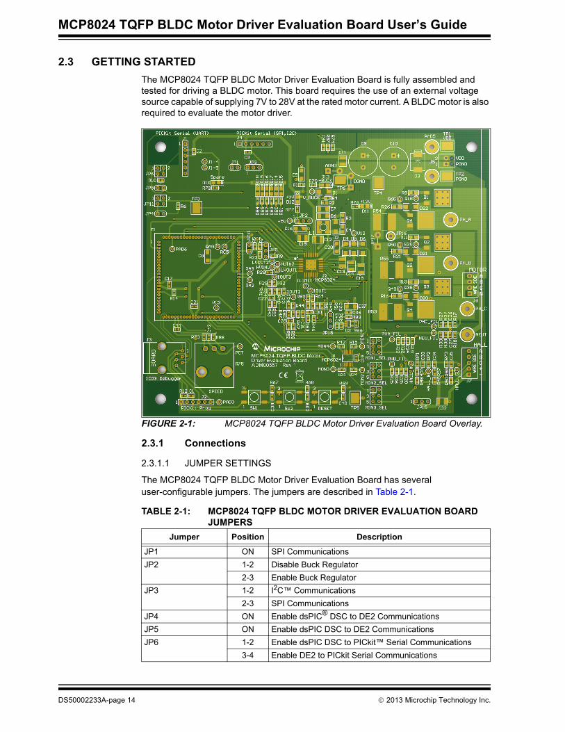
2.3 GETTING STARTEDThe MCP8024 TQFP BLDC Motor Driver Evaluation Board is fully assembled and tested for driving a BLDC motor. This board requires the use of an external voltage source capable of supplying 7V to 28V at the rated motor current. A BLDC motor is also required to evaluate the motor driver.
FIGURE 2-1: MCP8024 TQFP BLDC Motor Driver Evaluation Board Overlay.
2.3.1 Connections
2.3.1.1 JUMPER SETTINGS
The MCP8024 TQFP BLDC Motor Driver Evaluation Board has several user-configurable jumpers. The jumpers are described in Table 2-1.
TABLE 2-1: MCP8024 TQFP BLDC MOTOR DRIVER EVALUATION BOARD JUMPERS
Jumper Position Description
JP1 ON SPI CommunicationsJP2 1-2 Disable Buck Regulator
2-3 Enable Buck RegulatorJP3 1-2 I2C™ Communications
2-3 SPI CommunicationsJP4 ON Enable dsPIC® DSC to DE2 CommunicationsJP5 ON Enable dsPIC DSC to DE2 CommunicationsJP6 1-2 Enable dsPIC DSC to PICkit™ Serial Communications
3-4 Enable DE2 to PICkit Serial Communications
DS50002233A-page 14 2013 Microchip Technology Inc.

Installation and Operation
2.3.1.1.1 The jumpers and their use are described in Table 2-2.
JP9 1-2 CE Pull Up2-3 CE Pull Down
JP10 ON Routes DE2 to dsPIC DSC RP20/CN25/RC4 pinJP11 1-2 Enable DE2 to PICkit Serial Communications
3-4 Enable dsPIC DSC to PICkit Serial CommunicationsJP12 (MONITOR1)JP13 (MONITOR2)JP14 (MONITOR3)
1-2 Connect Phase Current to MONITORn3-4 Connect Filtered Phase Voltage to MONITORn5-6 Connect Hall Sensor to MONITORn
JP15 1-2 5V Hall Sensor Power Supply2-3 12V Hall Sensor Power Supply
JP16 — Sums Individual Phase Currents (soldered wire)JP17 — Select Individual Phase Currents (soldered wire)JP18 1-2 Current Sense Offset = 0.992V
2-3 Current Sense Offset = 0.0V
TABLE 2-1: MCP8024 TQFP BLDC MOTOR DRIVER EVALUATION BOARD JUMPERS (CONTINUED)
Jumper Position Description
TABLE 2-2: JUMPER DESCRIPTIONJumper Position Description
JP1 (used with JP3) ON Enables PICkit™ Serial SPI (J4) communications to the dsPIC® DSCJP2 1-2 Disables the MCP8024 buck regulator by connecting the FB pin to +5V
2-3 Enables the MCP8024 buck regulator by connecting the FB pin to the buck out-put voltage divider
JP3 (used with JP1) 1-2 Enables PICkit Serial I2C™ (J4) communications to the dsPIC DSC2-3 Enables PICkit Serial SPI (J4) communications to the dsPIC DSC
JP4 ON Enables the dsPIC DSC to Transmit to the MCP8024 DE2 pinJP5 ON Enables the dsPIC DSC to Receive from the MCP8024 DE2 pinJP6 1-2 Enables PICkit Serial UART (J1) Transmissions to the dsPIC DSC
3-4 Enables PICkit Serial UART (J1) Transmissions to the MCP8024 DE2 pinJP7 Permanent jumper wire connecting Digital ground to Power groundJP8 Permanent jumper wire connecting Analog ground to Power groundJP9 1-2 Connects the MCP8024 CE pin to a pull-up resistor
2-3 Connects the MCP8024 CE pin to a pull-down resistorJP10 ON Connects the dsPIC DSC RP20/CN25/RC4 pin to the MCP8024 DE2 pinJP11 1-2 Enables PICkit Serial UART (J1) Reception from the MCP8024 DE2 pin
3-4 Enables PICkit Serial UART (J1) Reception from the dsPIC DSCJP12 1-2 Connects the Phase A amplified motor current to the dsPIC DSC Monitor 1
input3-4 Connects the Phase A filtered motor current to the dsPIC DSC Monitor 1 input5-6 Connects the Phase A Hall-effect sensor input to the dsPIC DSC Monitor 1
inputJP13 1-2 Connects the Phase B amplified motor current to the dsPIC DSC Monitor 2
input3-4 Connects the Phase B filtered motor current to the dsPIC DSC Monitor 2 input5-6 Connects the Phase B Hall-effect sensor input to the dsPIC DSC Monitor 2
input
2013 Microchip Technology Inc. DS50002233A-page 15

MCP8024 TQFP BLDC Motor Driver Evaluation Board User’s Guide
The jumper settings for use with the sensorless trapezoidal drive firmware are described in Table 2-3.
2.3.1.2 POWERING THE MCP8024 TQFP BLDC MOTOR DRIVER EVALUATION BOARD (REFERENCE Figure 2-2)
1. Apply the input voltage to the input terminal block J5. The input voltage source should be limited to the 0V to +28V range. For nominal operation, the input voltage should be between +7.0V and +24V.
2. Connect the positive side of the input source (+) to pin 2 of J5. Connect the negative or return side (-) of the input source to pin 1 of J5. Refer to Figure 2-2.
JP14 1-2 Connects the Phase C amplified motor current to the dsPIC DSC Monitor 3 input
3-4 Connects the Phase C filtered motor current to the dsPIC DSC Monitor 3 input5-6 Connects the Phase C Hall-effect sensor input to the dsPIC DSC Monitor 3
inputJP15 1-2 Sets the Hall effect supply to +5V
2-3 Sets the Hall effect supply to +12VJP16 (used with JP17) Jumper wire connecting Phase B and Phase C sense resistors to Phase A
sense resistor for summing phase currentsJP17 (used with JP16) Jumper wire connecting Phase B and Phase C sense resistors to ground for
using individual phase currentsJP18 1-2 Sets the current sense amplifier offset voltage to 0.992 volts
2-3 Sets the current sense amplifier offset voltage to 0.0 volts
TABLE 2-2: JUMPER DESCRIPTION (CONTINUED)Jumper Position Description
TABLE 2-3: JUMPERS USED BY SENSORLESS TRAPEZOIDAL FIRMWAREJumper Position Description
JP2 2-3 Enable Buck RegulatorJP4 ON Enable dsPIC® DSC to DE2 CommunicationsJP5 ON Enable dsPIC DSC to DE2 CommunicationsJP6 OFF Disable dsPIC DSC to PICkit™ Serial Communications
OFF Disable DE2 to PICkit Serial CommunicationsJP9 2-3 CE Pull DownJP10 OFF Disconnect DE2 to dsPIC DSC RP20/CN25/RC4 pinJP11 OFF Disable DE2 to PICkit Serial Communications
OFF Disable dsPIC DSC to PICkit Serial CommunicationsJP12 (MONITOR1)JP13 (MONITOR2)JP14 (MONITOR3)
3-4 Connect Filtered Phase Voltage to MONITORn
JP16 OFF Deselect Summing Phase CurrentsJP17 ON Select Individual Phase CurrentsJP18 1-2 Current Sense Offset by 0.992V
DS50002233A-page 16 2013 Microchip Technology Inc.

Installation and Operation
FIGURE 2-2: Connection and Operation Diagram.
2.3.1.3 CONNECTING A MOTOR MCP8024 TQFP BLDC MOTOR DRIVER EVALUATION BOARD
Connect each phase winding of the three-phase BLDC motor to the appropriate terminal of the motor terminal block (J6), terminals A,B,C. The neutral winding, terminal N, is not necessary for the sensorless trapezoidal drive firmware provided for the evaluation board.
2.3.2 Operating a Motor1. Turn the Speed Adjust potentiometer (R75) fully counter-clockwise to obtain the
slowest speed setting. Now turn the Speed Adjust approximately ¼ turn clock-wise to allow for 25% motor speed.
2. Turn on the power supply connected to the board.3. Press and release the RUN switch (SW2) to start the motor.4. Turn the Speed Adjust potentiometer clockwise to increase motor speed, and
counter-clockwise to decrease motor speed. The Speed Adjust changes the PWM duty cycle of the PWM signals that are being sent to the MCP8024.
5. Press and release the RUN switch again to stop the motor.
VDD
GND
J5Input Power
J6Motor Connections
PICkit™ Header J2 Speed Adjust R75
RUN Switch SW2
RESET Switch
M1 dsPIC®
DSC PIM
J3 ICD 3 Header
2013 Microchip Technology Inc. DS50002233A-page 17

MCP8024 TQFP BLDC Motor Driver Evaluation Board User’s Guide
2.3.3 Indicator LEDsThe MCP8024 TQFP BLDC Motor Driver Evaluation Board has ten LEDs to indicate system status. Table 2-4 lists the LED indicators and their descriptions.
2.3.4 Test PointsThere are several test points on the board to allow probing of voltages, currents and signals.
TABLE 2-4: LED INDICATORSPCB Location Name Description
D10 SPARE Spare LED on RA4 portD11 +12V +12V LDO Voltage OperatingD12 +5V +5V LDO Voltage OperatingD13 +Buck Buck Output Voltage OperatingD14 PWM3H PWM Phase 3 high-side input to MCP8024D15 PWM3L PWM Phase 3 low-side input to MCP8024D16 PWM2H PWM Phase 2 high-side input to MCP8024D17 PWM2L PWM Phase 2 low-side input to MCP8024D18 PWM1H PWM Phase 1 high-side input to MCP8024D19 PWM1L PWM Phase 1 low-side input to MCP8024
TABLE 2-5: TEST POINTS DESCRIPTIONTest Point Name Description
TP1 VDD Power Supply (+)TP2 PGND Power Supply Ground (–)TP3 DE2 MCP8024 DE2 Communications SignalTP4 PGND Power Supply Ground (–)TP5 PGND Power Supply Ground (–)TP6 PGND Power Supply Ground (–)PHA_FIL PHA_FIL Filtered Phase A SignalPHB_FIL PHB_FIL Filtered Phase B SignalPHC_FIL PHC_FIL Filtered Phase C SignalNEU_FIL NEU_FIL Filtered Neutral SignalMON1 MON1 Monitor Signal 1: Connects to A/D Channel 3MON2 MON2 Monitor Signal 2: Connects to A/D Channel 4MON3 MON3 Monitor Signal 3: Connects to A/D Channel 5MON4 MON4 Monitor Signal 4: Connects to A/D Channel 6D14 PWM3H PWM Phase C High-side Input to MCP8024D15 PWM3L PWM Phase C Low-side Input to MCP8024D16 PWM2H PWM Phase B High-side Input to MCP8024D17 PWM2L PWM Phase B Low-side Input to MCP8024D18 PWM1H PWM Phase A High-side Input to MCP8024D19 PWM1L PWM Phase A Low-side Input to MCP8024PAD42 POT Speed Adjust Potentiometer. Clockwise increases voltage
(speed), counter-clockwise decreases voltage (speed).
DS50002233A-page 18 2013 Microchip Technology Inc.
Installation and Operation
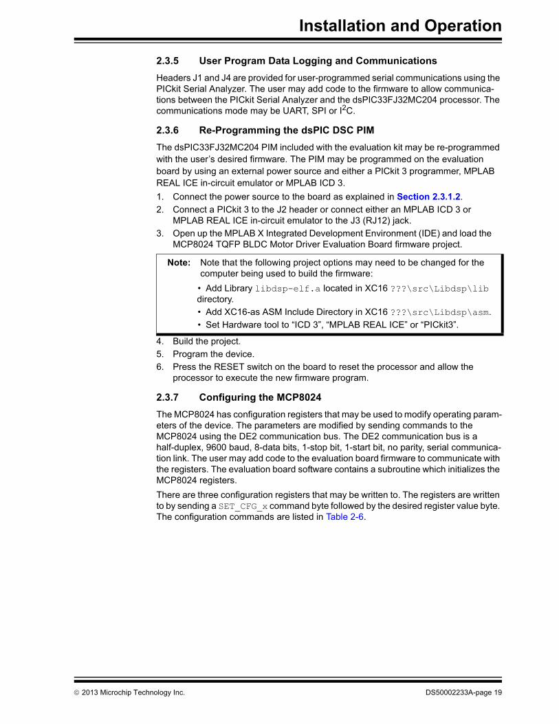
2.3.5 User Program Data Logging and CommunicationsHeaders J1 and J4 are provided for user-programmed serial communications using the PICkit Serial Analyzer. The user may add code to the firmware to allow communica-tions between the PICkit Serial Analyzer and the dsPIC33FJ32MC204 processor. The communications mode may be UART, SPI or I2C.
2.3.6 Re-Programming the dsPIC DSC PIMThe dsPIC33FJ32MC204 PIM included with the evaluation kit may be re-programmed with the user’s desired firmware. The PIM may be programmed on the evaluation board by using an external power source and either a PICkit 3 programmer, MPLAB REAL ICE in-circuit emulator or MPLAB ICD 3.1. Connect the power source to the board as explained in Section 2.3.1.2.2. Connect a PICkit 3 to the J2 header or connect either an MPLAB ICD 3 or
MPLAB REAL ICE in-circuit emulator to the J3 (RJ12) jack.3. Open up the MPLAB X Integrated Development Environment (IDE) and load the
MCP8024 TQFP BLDC Motor Driver Evaluation Board firmware project.
4. Build the project.5. Program the device.6. Press the RESET switch on the board to reset the processor and allow the
processor to execute the new firmware program.
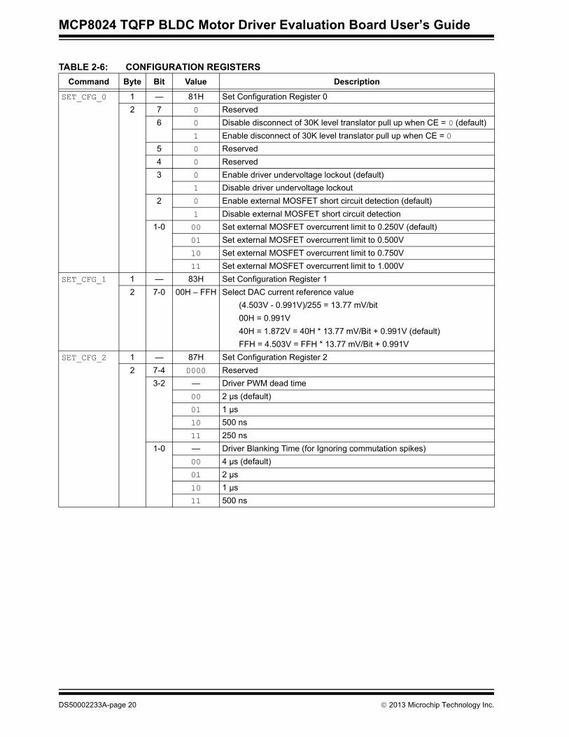
2.3.7 Configuring the MCP8024The MCP8024 has configuration registers that may be used to modify operating param-eters of the device. The parameters are modified by sending commands to the MCP8024 using the DE2 communication bus. The DE2 communication bus is a half-duplex, 9600 baud, 8-data bits, 1-stop bit, 1-start bit, no parity, serial communica-tion link. The user may add code to the evaluation board firmware to communicate with the registers. The evaluation board software contains a subroutine which initializes the MCP8024 registers.There are three configuration registers that may be written to. The registers are written to by sending a SET_CFG_x command byte followed by the desired register value byte. The configuration commands are listed in Table 2-6.
Note: Note that the following project options may need to be changed for the computer being used to build the firmware:
• Add Library libdsp-elf.a located in XC16 ???\src\Libdsp\lib directory.• Add XC16-as ASM Include Directory in XC16 ???\src\Libdsp\asm.• Set Hardware tool to “ICD 3”, “MPLAB REAL ICE” or “PICkit3”.
2013 Microchip Technology Inc. DS50002233A-page 19
MCP8024 TQFP BLDC Motor Driver Evaluation Board User’s Guide
TABLE 2-6: CONFIGURATION REGISTERSCommand Byte Bit Value Description
SET_CFG_0 1 — 81H Set Configuration Register 02 7 0 Reserved
6 0 Disable disconnect of 30K level translator pull up when CE = 0 (default)1 Enable disconnect of 30K level translator pull up when CE = 0
5 0 Reserved4 0 Reserved3 0 Enable driver undervoltage lockout (default)
1 Disable driver undervoltage lockout2 0 Enable external MOSFET short circuit detection (default)
1 Disable external MOSFET short circuit detection1-0 00 Set external MOSFET overcurrent limit to 0.250V (default)
01 Set external MOSFET overcurrent limit to 0.500V10 Set external MOSFET overcurrent limit to 0.750V11 Set external MOSFET overcurrent limit to 1.000V
SET_CFG_1 1 — 83H Set Configuration Register 12 7-0 00H – FFH Select DAC current reference value
(4.503V - 0.991V)/255 = 13.77 mV/bit00H = 0.991V40H = 1.872V = 40H * 13.77 mV/Bit + 0.991V (default)FFH = 4.503V = FFH * 13.77 mV/Bit + 0.991V
SET_CFG_2 1 — 87H Set Configuration Register 22 7-4 0000 Reserved
3-2 — Driver PWM dead time00 2 µs (default)01 1 µs 10 500 ns 11 250 ns
1-0 — Driver Blanking Time (for Ignoring commutation spikes)00 4 µs (default)01 2 µs10 1 µs11 500 ns
DS50002233A-page 20 2013 Microchip Technology Inc.
Installation and Operation
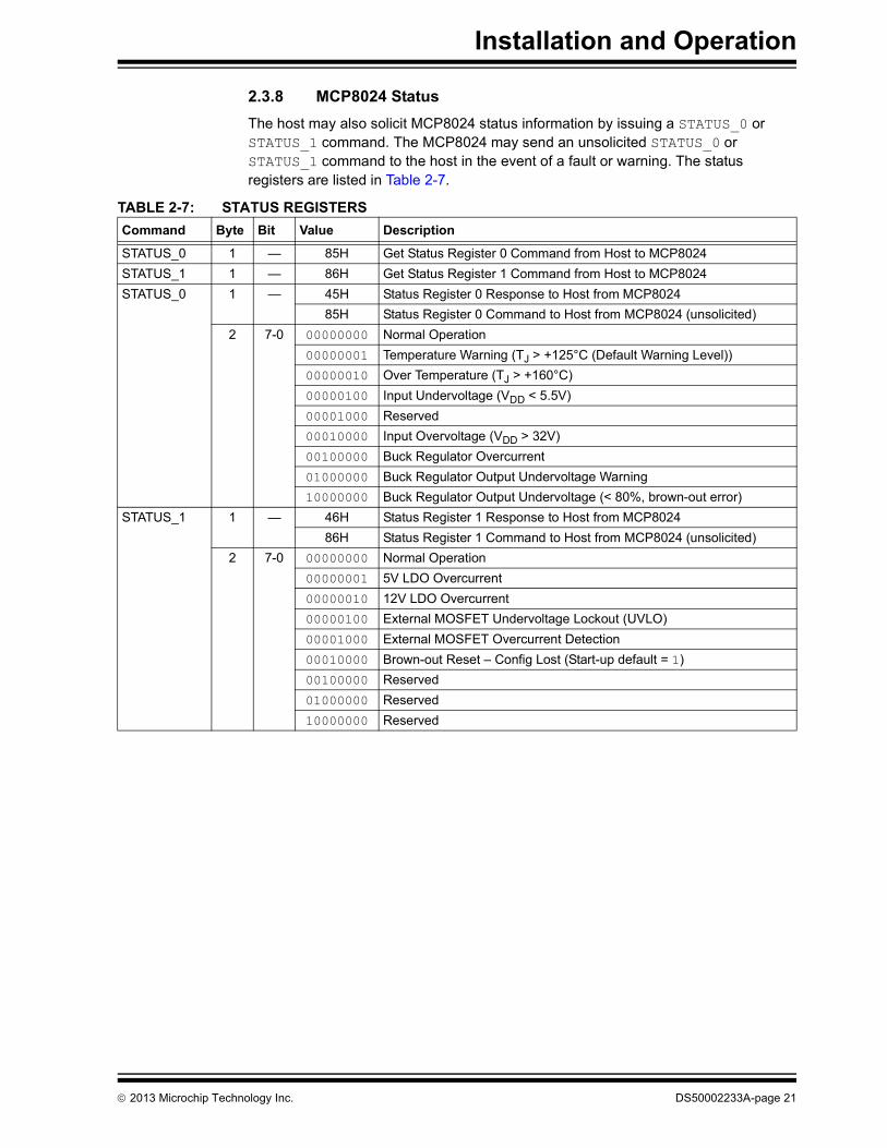
2.3.8 MCP8024 StatusThe host may also solicit MCP8024 status information by issuing a STATUS_0 or STATUS_1 command. The MCP8024 may send an unsolicited STATUS_0 or STATUS_1 command to the host in the event of a fault or warning. The status registers are listed in Table 2-7.
TABLE 2-7: STATUS REGISTERSCommand Byte Bit Value Description
STATUS_0 1 — 85H Get Status Register 0 Command from Host to MCP8024STATUS_1 1 — 86H Get Status Register 1 Command from Host to MCP8024STATUS_0 1 — 45H Status Register 0 Response to Host from MCP8024
85H Status Register 0 Command to Host from MCP8024 (unsolicited)2 7-0 00000000 Normal Operation
00000001 Temperature Warning (TJ > +125°C (Default Warning Level))00000010 Over Temperature (TJ > +160°C)00000100 Input Undervoltage (VDD < 5.5V)00001000 Reserved00010000 Input Overvoltage (VDD > 32V)00100000 Buck Regulator Overcurrent01000000 Buck Regulator Output Undervoltage Warning10000000 Buck Regulator Output Undervoltage (< 80%, brown-out error)
STATUS_1 1 — 46H Status Register 1 Response to Host from MCP802486H Status Register 1 Command to Host from MCP8024 (unsolicited)
2 7-0 00000000 Normal Operation00000001 5V LDO Overcurrent00000010 12V LDO Overcurrent00000100 External MOSFET Undervoltage Lockout (UVLO)00001000 External MOSFET Overcurrent Detection00010000 Brown-out Reset – Config Lost (Start-up default = 1)00100000 Reserved01000000 Reserved10000000 Reserved
2013 Microchip Technology Inc. DS50002233A-page 21

MCP8024 TQFP BLDC Motor Driver Evaluation Board User’s Guide
NOTES:
DS50002233A-page 22 2013 Microchip Technology Inc.

MCP8024 TQFP BLDC MOTOR DRIVER
EVALUATION BOARD USER’S GUIDEAppendix A. Schematic and Layouts
A.1 INTRODUCTIONThis appendix contains the following schematics and layouts for the MCP8024 TQFP BLDC Motor Driver Evaluation Board:• Board – Schematic• Board – Top Silk Layer• Board – Top Metal Layer• Board – Mid1 Metal Layer• Board – Mid2 Metal Layer• Board – Bottom Metal Layer
2013 Microchip Technology Inc. DS50002233A-page 23

MC
P8024 TQFP B
LDC
Motor D
river Evaluation Board U
ser’s Guide
DS
50002233A-page 24
2013 M
icrochip Technology Inc.
PGND
NEUT
PH_C
PH_A
PGND
PGND
PH_B
3.3V
Isense B Isense C
AGND
PGNDVDD
VDD
HALL +
HALL C
HALL A
MOTOR
PAD4
DGND
2.4KR35
1R1
100pF25V
C34
2.4KR37
100pF25V
C35
47K
R58
4.7KR49
4.7KR50
PAD22
PAD16
PAD20
PGND
PGND
PAD9
TP2
VDD
11
22
J5
PAD5
TP1
HALL B
HALL -
FDD
10A
N06
A0
Q1
FDD
10A
N06
A0
Q6
11KRFB2
R4
5V TranszorbD1
0.047uF25V
C24
90.9KR71
.015W
R53
FDD
10A
N06
A0
Q3
FDD
10A
N06
A0
Q4
22KR19
0.047uF25V
C25
47K
R57
90.9KR72
1 uF50V
C11
22KR17
)/RFB2
VDD Max = 32V
100pF25V
C33
4.7KR48
300R27
2.4KR36
FDD
10A
N06
A0
Q5
300R22
22KR18
FDD
10A
N06
A0
Q2
1
JP15
PAD23
3
4
2
1
J6
0.047uF25V
C26
47K
R56
90.9KR73
.015W
R55
22KR20
300R25
470 uF50V
C10
5
2
1
3
4
J7
+3.3V
12V_LDO
5V_LDO
5V_LDO
AVDD
HALL_A HALL_B HALL_C
ISENSE_B ISENSE_C
PHA_FIL
PHB_FIL
PHC_FIL
VDD
SMCJ30A
D3
18 A
WG
Wire
JP7
18 A
WG
Wire
JP8
DGND AGND
MCP8024 Buck
Buck Feedback (FB)18KRFB1
R2
470 uF50V
C9
0.047uF25V
C27
300R30
2.4KR38
NEU_FIL
PAD17
PAD14
PAD34 PAD35NEU_FIL PHC_FIL
PHA_FIL PHB_FIL
1 uF50V
C32
+12V Hall Effect Supply
+5V Hall Effect Supply
10 uF16V
C5
PAD39 PAD40PAD38
JP17
JP16DNP
1JP2
ISENSE_BL
ISENSE_CL
A.2 BOARD – SCHEMATIC
SPI
RX
0.992V
VD
D
GN
D
CLK
AU
X
PAD6
DGND
RC
3
RC
5
GN
D
SDO
GND
ICSP CLK
VDDGND
SPI_SDO
I2C_CLK, SPI_CLK I2C
TX +V
Av=11
Q3G
Q1G
SDI
SCK
/CS
+V
ICSP DAT
/MCLR
JP5
I2C_SDA, SPI_SDI
SPI
SPI_/SS/M
CLR
MON3
MON2
MON1
DA
TA
2 4
1 3
SW2
SW2
1uF10V
C38
47KR67
1uF10V
C17
DGND
2 4
1 3
SW3
RESET
1uF10V
C40
PAD1J1-4
PAD2J1-5
AGND
47K
R32
PAD30
DGND
DGNDPGND
1KR59
1KR52
1KR43
47KR28
3.74KR34
47KR23
3.74KR60
PGND
1526 Hz Filter
0.022uF25V
C31
PGND
3.74KR47
PAD33
PAD41
AGND
DGND
1KR85
10.7KR86
PGND
24.9KR66
47KR51
7.5KR89
0.1uF10V
C36
1KR63
1KR46
4.99R3
1800 pF50V
C4
TP4
PGND
TP5
10
R21
10
R11
10
R13
SS24-TP
D5
DGND
3.3 uH744-042-003
L1
Q2G
0.1uF10V
C41
DGND DGND
100R70
13
210KR75
100R88
0.1uF10V
C42
1uF10V
C21
100pFC22
GREEN
D14
PWM3H
47KR40
47KR7
GREEN
D19
PWM1L
PGND
0.022uF25V
C29
AGND
100pFC30
10 uF50V
C12
10
R9
10
R16
10
R26
.015W
R54
AGND
1526 Hz Filter
HVIN2
JP10DE2 To RC4
0.992V
152.6 Hz Filter
PGND
Isense A
Q5G
Vbuck = 1.25 (RFB1 + RFB2
30KR74
2 4
1 3
SW1
SW1
47KR14
1 2
3 4
JP6
SE
R_T
X_S
EL
JP1
DGND
1uF10V
C39
3.74KR41
HVIN1LVOUT1
Av=11
1KR33
LVOUT2
47KR64 3.74K
R6147KR62
Av=11
47KR44
3.74KR45
SS24-TP
D4
TP6
Q6G
Q4G
SS24-TP
D6
DGND
2KR87
52 61 43
J2PICKit Prog
5
2
6
1
4
3
J4
PICKit Serial (SPI,I2C)
6
34
12
5
J3
ICD3 Debugger
100pFC28
0.022uF25V
C23
52 61 43
J1PICKit Serial (UART)
0.1uF10V
C43
GREEN
D15
PWM3L
MCP6021
VIN
+3
Vss
2
VO
UT
1V
DD
5
VIN
-4 U3
SS24-TP
D2
1
6
2
34
5
JP12
MO
N1_
SE
L
DSPIC_PIM_LNK
PG
ED
327
AV
DD
30N
C96
NC
33
VS
S36
NC
90
NC
39N
C87
AN
442
RB
484
RA
481
NC
48
PW
M1H
299
PW
M1L
193
AN
6_(J
umpe
r)45
RP
23_R
B7
78
NC52
NC55
NC58
NC61
OSCO/CN29/RA364
NC67
RP770
NC73
PG
EC
326
NC
29N
C28
AV
SS
31N
C95
AN
235
NC
38
AN
341
NC
34
VD
D37
NC
40
AN
543
NC
91
NC
88
NC
86
NC
89
NC
92
RA
883
VC
AP85
NC
47
NC
50N
C49
NC
46
NC51
NC54
NC56
NC57
NC59
NC60
NC62
OSCI/CN30/RA263
NC66
SCL1_RP2468
SDA1_RP2569
RA771
RP20_CN25_RC472
NC74
NC75
NC
79N
C80
PW
M1L
310
0
PW
M1L
298
RA
10_(
Jum
per)
97
NC53
VSS65
RP
22_R
C6
77
RP
21_R
C5
76
AN124
NC21
CN22_RB818
VSS15
NC12
NC9
NC6
PWM1H33
AN025
NC22
RP919
NC17
VDD16
NC14
/MCLR13
AN720
NC10
NC8
NC7
NC4
NC5
NC1
NC2
RA
982
AN
8_R
P18
_RC
232
NC23
PW
M1H
194
NC11
RP
19_C
N28
_RC
344
M1
DSPIC33FJ32MC204_PIM
ISE
NS
E2-
13P
WM
2H48
ILIM
IT15
IOU
T116
PW
M3H
46
PW
M3L
45
ISE
NS
E+
18
PG
ND
19C
AP1
43
CA
P242
LA21
LB22
FB40
VD
D39
PG
ND
24LX
37
PGND7
LV_OUT18
HV_IN25
LV_OUT24
PWM1H2
PWM1L1
HB26
HA27
PHB29
PHA30
VBB32
VBA33
PGND35
PGND36
IOUT212
IOUT39
CE3
HV_IN16
ISE
NS
E2+
14
ISE
NS
E1-
17
PG
ND
20
LC23
PW
M2L
47
DE
244
5VLD
O41
VD
D38
HC25
PHC28
VBC31
12VLDO34
ISENSE3+11
ISENSE3-10
U2
MCP8024
/MCLR_VPP
/MCLR_VPP
/MC
LR_V
PP
+3.3
V
+3.3V
+3.3
V
+3.3
V
+3.3V
+3.3
V
+3.3
V
+3.3V
+3.3V
+3.3V
5V_L
DO
12V_LDO
AVDD
AV
DD
AVDD
AVDDAVDD
DE2
DSPIC_RX
DSPIC_RX
DSPIC_RX
DSPIC_TX
DSPIC_TX
DSPIC_TX
HALL_A
HALL_B
HALL_C
ILIMIT
ILIMIT
IOUTA
IOUTA
IOUTA
IOU
TB
IOUTB
IOUTB
IOUTC
IOU
TC
IOUTC
ISENSE_B
ISENSE_C
MO
NIT
OR
_1M
ON
ITO
R_2
MO
NIT
OR
_3
MO
NIT
OR
_4
PGC
PG
CP
GD
PGD
DGND
DGND
DGND
PGNDPGND
DGND
PGNDPGND
PGND
PGND
PHA_FIL
PHB_FIL
PHC_FIL
PO
T
PO
T
PWM1H1
PW
M1H
1
PW
M1H
1
PWM1H2
PW
M1H
2
PW
M1H
2
PWM1H3
PW
M1H
3
PW
M1H
3
PW
M1L
1
PWM1L1
PW
M1L
1
PWM1L2
PW
M1L
2
PW
M1L
2
PWM1L3
PW
M1L
3
PW
M1L
3
RP22
RP
22R
P23
RP23
RP24
RP24
RP25
RP25
SER_RX
SE
R_R
X
SER_TX
SE
R_T
X
SP
AR
E_L
ED
SP
AR
E_L
ED
SW1
SW
1
SW2
SW
2
VD
D
VDD_DIV16
VD
D_D
IV16
VOFFSET
VO
FFS
ET
VOFFSET
VOFFSET
JP18
+3.3V
DGNDDGNDDGNDDGNDDGND
RA
9
-9
+10
8VD
D4
AG
ND
11
U1:3MCP6024
-6
+5
7U1:2MCP6024
-2
+3
1U1:1MCP6024
MONITOR_1
MONITOR_2
MONITOR_3
-13
+12
14U1:4
MCP6024
AV
DD
2.49KR29
2.49KR39
1-2 = I2C2-3 = SPI
1
+3.3
V
1JP9CE
DGND
47KR8
1 uF50V
C19
PHA
PHB
PHC
2.49KR15
2.49KR65
1uF10V
C1
1uF10V
C2
1uF10V
C3
47KR5
+3.3V
AGND
1uF10V
C18
47KR68
47KR69
1KR84
1KR83
1KR82
1KR81
1KR80
1KR79
GND
1
DE2
PAD10
PGND
5V_L
DO
5V LDO
PGND
10 uF16V
C20
PAD15V12
12V_LDO
Faraday Shield Ground Plane
MONITOR_4
MON4NEU_FIL
1 uF50V
C131 uF50V
C141 uF50V
C15
12V
_LD
O
PGND
3.74KR76
2KR77
1KR78
PAD19
IOUT1
IOUT2
47KR12
+3.3
V
1 2
3 4
JP11
SER
_RX
_SE
L
1
6
2
34
5
JP13
MO
N2_
SE
L
1
6
2
34
5
JP14
MO
N3_
SE
L
2KR6
2KR10
10 uF16V
C7
10 uF16V
C6
10 uF16V
C16
10 uF16V
C37
10 uF16V
C8
3-4
1-2
JP113-4
JP81-2
JP9
JP61-2
1-22-3
JP3
1-2JP1 ON
JP2
JP15 2-3
1-2
--------
2-3
JP4 ON
1-2
PositionJumper
2-3
5V Hall Sensor Power Supply
Routes DE2 to dsPIC RP20/CN25/RC4
CE Enabled
Enable dsPIC/Serial PICkit Comms
I2C CommunicationsSPI Communications
SPI CommunicationsDisable Buck Regulator
12V Hall Sensor Power Supply
Connect Phase Current To MONITOR1
Digital Ground Star Connection
CE Disabled
Enable dsPIC/DE2 Communication
Description
Enable Buck Regulator
JP12
JP5 Enable dsPIC/DE2 Communication
JP7 --------Analog Ground Star Connection
JP10
3-4 Enable DE2/Serial PICkit Comms
ON
ON
Enable DE2/Serial PICkit Comms
Enable dsPIC/Serial PICkit Comms
2-3
1-2
Current Sense Offset = 0.0V
Current Sense Offset = 0.992VJP16
JP13JP14
Connect Filtered Phase To MONITOR2Connect Hall Sensor To MONITOR35-6
PAD3
Sums Phase CurrentsJP18 ----JP17 ---- Selects Individual Phase Currents
TP3
JP3
GREEN
D16
PWM2HGREEN
D17
PWM2LGREEN
D18
PWM1HGREEN
D13
+BUCKGREEN
D12
+5VGREEN
D11
+12VGREEN
D10
Spare
2.49KR24
2.49KR31
2.49KR42
PAD42
POT
SMAJ33CAD22
SMAJ33CAD20
SMAJ33CAD21
RA3RA2
JP4
ISENSE_BL
ISENSE_CL
1uF10V
C44
AGND
Schematic and Layouts
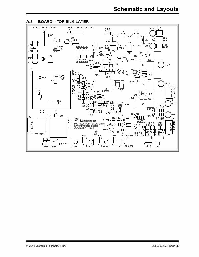
A.3 BOARD – TOP SILK LAYER
2013 Microchip Technology Inc. DS50002233A-page 25

MCP8024 TQFP BLDC Motor Driver Evaluation Board User’s Guide
A.4 BOARD – TOP METAL LAYER
DS50002233A-page 26 2013 Microchip Technology Inc.

Schematic and Layouts
A.5 BOARD – MID1 METAL LAYER
2013 Microchip Technology Inc. DS50002233A-page 27
MCP8024 TQFP BLDC Motor Driver Evaluation Board User’s Guide
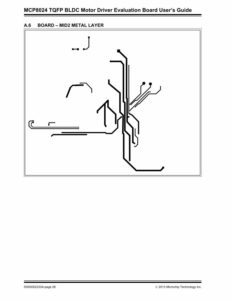
A.6 BOARD – MID2 METAL LAYER
DS50002233A-page 28 2013 Microchip Technology Inc.
Schematic and Layouts
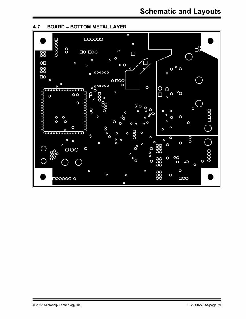
A.7 BOARD – BOTTOM METAL LAYER
2013 Microchip Technology Inc. DS50002233A-page 29

MCP8024 TQFP BLDC Motor Driver Evaluation Board User’s Guide
NOTES:
DS50002233A-page 30 2013 Microchip Technology Inc.
MCP8024 TQFP BLDC MOTOR DRIVER
EVALUATION BOARD USER’S GUIDEAppendix B. Bill of Materials (BOM)
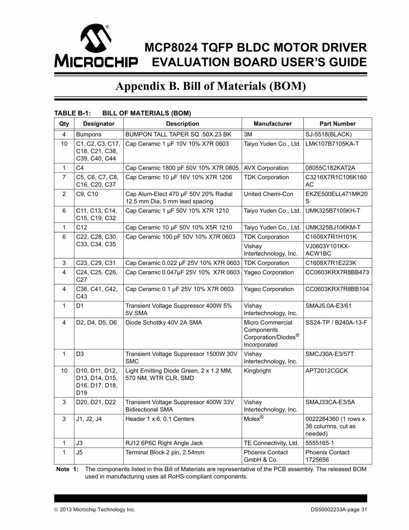
TABLE B-1: BILL OF MATERIALS (BOM)Qty Designator Description Manufacturer Part Number
4 Bumpons BUMPON TALL TAPER SQ .50X.23 BK 3M SJ-5518(BLACK)10 C1, C2, C3, C17,
C18, C21, C38, C39, C40, C44
Cap Ceramic 1 µF 10V 10% X7R 0603 Taiyo Yuden Co., Ltd. LMK107B7105KA-T
1 C4 Cap Ceramic 1800 pF 50V 10% X7R 0805 AVX Corporation 08055C182KAT2A7 C5, C6, C7, C8,
C16, C20, C37Cap Ceramic 10 µF 16V 10% X7R 1206 TDK Corporation C3216X7R1C106K160
AC2 C9, C10 Cap Alum-Elect 470 µF 50V 20% Radial
12.5 mm Dia, 5 mm lead spacingUnited Chemi-Con EKZE500ELL471MK20
S6 C11, C13, C14,
C15, C19, C32Cap Ceramic 1 µF 50V 10% X7R 1210 Taiyo Yuden Co., Ltd. UMK325B7105KH-T
1 C12 Cap Ceramic 10 µF 50V 10% X5R 1210 Taiyo Yuden Co., Ltd. UMK325BJ106KM-T6 C22, C28, C30,
C33, C34, C35Cap Ceramic 100 pF 50V 10% X7R 0603 TDK Corporation C1608X7R1H101K
Vishay Intertechnology, Inc.
VJ0603Y101KX-ACW1BC
3 C23, C29, C31 Cap Ceramic 0.022 µF 25V 10% X7R 0603 TDK Corporation C1608X7R1E223K4 C24, C25, C26,
C27Cap Ceramic 0.047µF 25V 10% X7R 0603 Yageo Corporation CC0603KRX7R8BB473
4 C36, C41, C42, C43
Cap Ceramic 0.1 µF 25V 10% X7R 0603 Yageo Corporation CC0603KRX7R8BB104
1 D1 Transient Voltage Suppressor 400W 5% 5V SMA
Vishay Intertechnology, Inc.
SMAJ5.0A-E3/61
4 D2, D4, D5, D6 Diode Schottky 40V 2A SMA Micro Commercial Components Corporation/Diodes® Incorporated
SS24-TP / B240A-13-F
1 D3 Transient Voltage Suppressor 1500W 30V SMC
Vishay Intertechnology, Inc.
SMCJ30A-E3/57T
10 D10, D11, D12, D13, D14, D15, D16, D17, D18, D19
Light Emitting Diode Green, 2 x 1.2 MM, 570 NM, WTR CLR, SMD
Kingbright APT2012CGCK
3 D20, D21, D22 Transient Voltage Suppressor 400W 33V Bidirectional SMA
Vishay Intertechnology, Inc.
SMAJ33CA-E3/5A
3 J1, J2, J4 Header 1 x 6, 0.1 Centers Molex® 0022284360 (1 rows x 36 columns, cut as needed)
1 J3 RJ12 6P6C Right Angle Jack TE Connectivity, Ltd. 5555165-11 J5 Terminal Block 2 pin, 2.54mm Phoenix Contact
GmbH & Co.Phoenix Contact 1725656
Note 1: The components listed in this Bill of Materials are representative of the PCB assembly. The released BOM used in manufacturing uses all RoHS-compliant components.
2013 Microchip Technology Inc. DS50002233A-page 31

MCP8024 TQFP BLDC Motor Driver Evaluation Board User’s Guide
1 J6 Terminal Block 4 pin, 2.54mm Phoenix Contact GmbH & Co.
Phoenix Contact 1725672
1 J7 Terminal Block 5 pin, 2.54mm Phoenix Contact GmbH & Co.
Phoenix Contact 1725686
14 JP** CONN JUMPER SHORTING GOLD FLASH
Sullins Connector Solutions
SPC02SYAN
4 JP1, JP4, JP5, JP10
Header 1 x 2, 0.1 Centers Molex 0022284360 (1 rows x 36 columns, cut as needed)
5 JP2, JP3, JP9, JP15, JP18
Header 1 x 3, 0.1 Centers Molex 0022284360 (1 rows x 36 columns, cut as needed)
2 JP6, JP11 Header 2 x 2, 0.1 Centers Molex 0702800448 (2 rows x 50 columns, cut as needed)
3 JP7, JP8, JP17 Wire 18 AWG, As needed — 18 AWG bare wire as needed
3 JP12, JP13, JP14
Header 2 x 3, 0.1 Centers Molex 0702800448 (2 rows x 50 columns, cut as needed)
1 L1 Inductor 3.3 µH Wurth® Group 744-042-0031 M1 dsPIC33F GP 44P QFN TO 100P PIM
dsPIC33FJ32MC204 Microchip Technology Inc.
MA330017
4 M1 Headers Fine Pitch Header, 1 row 25 columns Samtec, Inc. MTMS-125-01-G-S-2306 Q1, Q2, Q3, Q4,
Q5, Q6MOSFET N-CH 60V 50A D-PAK Fairchild
Semiconductor®FDD10AN06A0
1 PCB Printed Circuit Board – MCP8024 TQFP BLDC Motor Driver Evaluation Board
Microchip Technology Inc.
104-10239
1 R1 RES 1.00 1/10W 1% 0603 SMD Yageo Corporation RC0603FR-071RL1 R2 RES 18.0 k 1/10W 1% 0603 SMD Yageo Corporation RC0603FR-0718KL1 R3 RES 4.99 1/8W 1% 0805 SMD Yageo Corporation RC0805FR-074R99L1 R4 RES 11.0 k 1/10W 1% 0603 SMD Yageo Corporation/
Panasonic® - ECGRC0603FR-0711KL/ERJ-3EKF1102V
19 R5, R7, R8, R12, R14, R23, R28, R32, R40, R44, R51, R56, R57, R58, R62, R64, R67, R68, R69
RES 47.0 k 1/10W 1% 0603 SMD Yageo Corporation RC0603FR-0747KL
3 R6, R10, R87 RES 2.00 k 1/10W 1% 0603 SMD Yageo Corporation RC0603FR-072KL6 R9, R11, R13,
R16, R21, R26RES 10.0 1/8W 1% 0805 SMD Yageo Corporation RC0805FR-0710RL
7 R15, R24, R29, R31, R39, R42, R65
RES 2.49 k 1/10W 1% 0603 SMD Yageo Corporation RC0603FR-072K49L
4 R17, R18, R19, R20
RES 22.0 k 1/10W 1% 0603 SMD Yageo Corporation RC0603FR-0722KL
4 R22, R25, R27, R30
RES 300 1/10W 1% 0603 SMD Yageo Corporation RC0603FR-07300RL
TABLE B-1: BILL OF MATERIALS (BOM) (CONTINUED)Qty Designator Description Manufacturer Part Number
Note 1: The components listed in this Bill of Materials are representative of the PCB assembly. The released BOM used in manufacturing uses all RoHS-compliant components.
DS50002233A-page 32 2013 Microchip Technology Inc.

Bill of Materials (BOM)
14 R33, R43, R46, R52, R59, R63, R78, R79, R80, R81, R82, R83, R84, R85
RES 1.00 k 1/10W 1% 0603 SMD Yageo Corporation RC0603FR-071KL
7 R34, R41, R45, R47, R60, R61, R76
RES 3.74 k 1/10W 1% 0603 SMD Yageo Corporation RC0603FR-073K74L
4 R35, R36, R37, R38
RES 2.40 k 1/10W 1% 0603 SMD Yageo Corporation RC0603FR-072K4L
3 R48, R49, R50 RES 4.70 k 1/10W 1% 0603 SMD Yageo Corporation RC0603FR-074K7L3 R53, R54, R55 RES .010 5W 1% FLAT SMD TT Electronics
Plc./IRCOARSXPR010FLF
1 R66 RES 24.9 k 1/10W 1% 0603 SMD Yageo Corporation RC0603FR-0724K9L2 R70, R88 RES 100 1/10W 1% 0603 SMD Yageo Corporation RC0603FR-07100RL3 R71, R72, R73 RES 90.9 k 1/10W 1% 0603 SMD Yageo Corporation RC0603FR-0790K9L1 R74 RES 30.0 k 1/10W 1% 0603 SMD Yageo Corporation RC0603FR-0730KL1 R75 Potentiometer 10 k 1/8W CARB VERTI-
CALCTS® Corporation 296UD103B1N
1 R77 RES 2.00 k 1/10W 1% 0603 SMD Yageo Corporation RC0603FR-072KL1 R86 RES 10.7 k 1/10W 1% 0603 SMD Yageo Corporation RC0603FR-0710K7L1 R89 RES 7.50 k 1/10W 1% 0603 SMD Yageo Corporation RC0603FR-077K5L3 SW1, SW2,
SW3SWITCH TACTILE SPST-NO 0.05A 12V E-Switch®, Inc. TL330INF260QG
6 TP1, TP2, TP3, TP4, TP5, TP6
SMT Test Point Keystone Electronics Corp.
5016
1 U1 MCP6024 Quad Op Amp – Plastic TSSOP, 14-lead
Microchip Technology Inc.
MCP6024-E/ST
1 U2 3-Phase Brushless DC (BLDC) Motor Gate Driver with Power Module - Plastic Thin Quad Flatpack with Exposed Pad - 7x7 mm body, 48-lead, Thermally Enhanced (EP)
Microchip Technology Inc.
MCP8024-H/PT
1 U3 MCP6021 Single Op Amp - Plastic Small Outline Transistor (SOT-23), 5-lead
Microchip Technology Inc.
MCP6021T-E/OT
TABLE B-1: BILL OF MATERIALS (BOM) (CONTINUED)Qty Designator Description Manufacturer Part Number
Note 1: The components listed in this Bill of Materials are representative of the PCB assembly. The released BOM used in manufacturing uses all RoHS-compliant components.
2013 Microchip Technology Inc. DS50002233A-page 33

MCP8024 TQFP BLDC Motor Driver Evaluation Board User’s Guide
NOTES:
DS50002233A-page 34 2013 Microchip Technology Inc.
MCP8024 TQFP BLDC MOTOR DRIVER
EVALUATION BOARD USER’S GUIDEAppendix C. Software
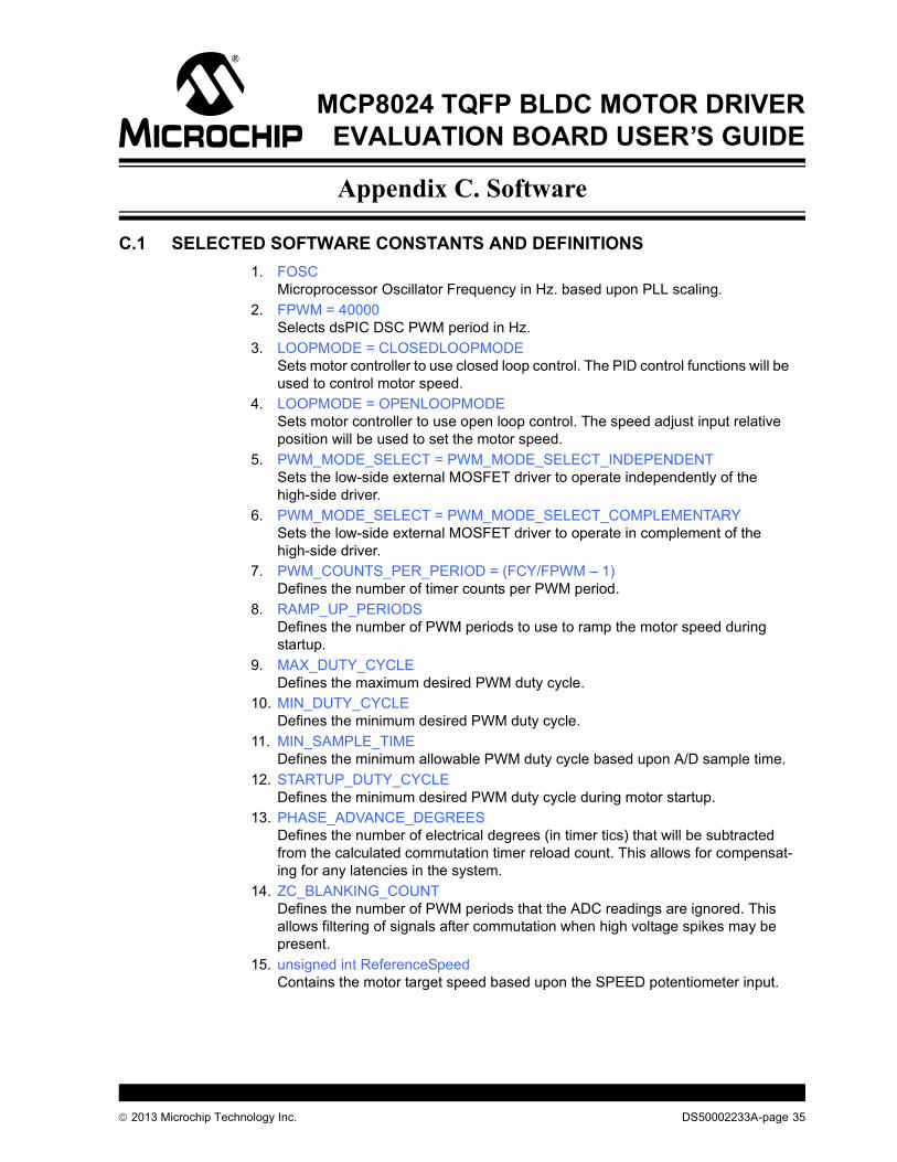
C.1 SELECTED SOFTWARE CONSTANTS AND DEFINITIONS1. FOSC
Microprocessor Oscillator Frequency in Hz. based upon PLL scaling.2. FPWM = 40000
Selects dsPIC DSC PWM period in Hz.3. LOOPMODE = CLOSEDLOOPMODE
Sets motor controller to use closed loop control. The PID control functions will be used to control motor speed.
4. LOOPMODE = OPENLOOPMODESets motor controller to use open loop control. The speed adjust input relative position will be used to set the motor speed.
5. PWM_MODE_SELECT = PWM_MODE_SELECT_INDEPENDENTSets the low-side external MOSFET driver to operate independently of the high-side driver.
6. PWM_MODE_SELECT = PWM_MODE_SELECT_COMPLEMENTARYSets the low-side external MOSFET driver to operate in complement of the high-side driver.
7. PWM_COUNTS_PER_PERIOD = (FCY/FPWM – 1)Defines the number of timer counts per PWM period.
8. RAMP_UP_PERIODSDefines the number of PWM periods to use to ramp the motor speed during startup.
9. MAX_DUTY_CYCLEDefines the maximum desired PWM duty cycle.
10. MIN_DUTY_CYCLEDefines the minimum desired PWM duty cycle.
11. MIN_SAMPLE_TIMEDefines the minimum allowable PWM duty cycle based upon A/D sample time.
12. STARTUP_DUTY_CYCLEDefines the minimum desired PWM duty cycle during motor startup.
13. PHASE_ADVANCE_DEGREESDefines the number of electrical degrees (in timer tics) that will be subtracted from the calculated commutation timer reload count. This allows for compensat-ing for any latencies in the system.
14. ZC_BLANKING_COUNTDefines the number of PWM periods that the ADC readings are ignored. This allows filtering of signals after commutation when high voltage spikes may be present.
15. unsigned int ReferenceSpeedContains the motor target speed based upon the SPEED potentiometer input.
2013 Microchip Technology Inc. DS50002233A-page 35

MCP8024 TQFP BLDC Motor Driver Evaluation Board User’s Guide
16. int DesiredSpeedContains the desired motor target speed based upon the SPEED potentiometer input.
17. int CurrentSpeedContains the current motor speed.
18. unsigned int SpeedControl_PProportional term of the closed loop PID control function. Sets the motor gain coefficient for the current speed error.
19. unsigned int SpeedControl_IIntegral term of the closed loop PID control function. Sets the motor gain coeffi-cient for previous speed changes.
20. unsigned int SpeedControl_DDerivative term of the closed loop PID control function. Sets the motor gain coef-ficient for predicted errors in the motor control loop.
21. PWM_STATE[]Array containing the high-side and low-side gate driver output states for a given step of the six-step commutation algorithm.
22. BOOTSTRAP_CHARGE_STATEHigh-side and low-side gate driver output states for charging the bootstrap capacitors prior to motor startup.
23. MOTOR_SHUTDOWN_STATEHigh-side and low-side gate driver output states that may be used when shutting down the motor.
24. ADC_MASK[]A/D Back EMF mask used for majority detection.
25. ADC_XOR[]A/D Back EMF mask used for majority detection.
26. ADC_BEMF_FILTER[]A/D Back EMF filter table used to determine next commutation time.
C.2 DSPIC33FJ32MC204 PIM PORT USAGE
Port Name Description
/* Port A */PORTA.2 DEBUG_PORT1 General purpose debug portPORTA.3 DEBUG_PORT2 General purpose debug portPORTA.4 SPARE_LED Spare LED portPORTA.7 MCP8024_CE 1 = Enables MCP8024 output
0 = Disables MCP8024 outputPORTA.8 SW1 Spare push button input/* Port B */PORTB.4 SW2 ‘On/Off’ switch inputPORTB.8 ILIMIT_OUT MCP8024 ILIMIT_OUT signal:
1 = OK 0 = Fault/Current Limit
/* Port C */PORTC.5 DEBUG_PORT3 General purpose debug port
DS50002233A-page 36 2013 Microchip Technology Inc.

Software
C.3 MPLAB X IDE COMPILER STARTUP1. Start the MPLAB X IDE compiler (not supplied, available on Microchip web
page).2. From the toolbar, select File > Open Project.3. Browse to the evaluation board source code path.4. Select the existing project file named MCP8024_ADM00557_EVAL.5. In the Projects window, right mouse-click on MCP8024_ADM00557_EVAL and
select Properties. The page contains the project properties. Processor, Compiler, Hardware and Config settings may be changed here.
6. Right click on the MCP8024_ADM00557_EVAL again and select the “Make and Program Device” option. This will compile the firmware and download to the programming hardware.
7. The compiler results will be displayed in the Output window frame. Verify success.
C.4 MPLAB X IDE AND PICkit 3 PROGRAMMER EXERCISE1. Start the MPLAB X (not supplied, available on Microchip web page).2. From the toolbar, select File > Open Project.3. Browse to the evaluation board source code path.4. Select the existing workspace directory named MCP8024_ADM00557_EVAL or
create a new one.5. Connect the PICkit 3 programmer to header J2 on the evaluation board. Align
Pin 1 of the header with the Pin 1 mark on the programmer.6. Set the bench power supply voltage control to the minimum voltage output.7. Turn on the power supply and set the output voltage to 14V. Turn off the power
supply.8. Connect the bench power supply to the evaluation board. Connect +V(14V) to
J5-2 and –V (Ground) to J5-1.9. Turn on the power supply.10. Right click on MCP8024_ADM00557_EVAL in the Projects window and select the
“Make and Program Device” option. This will compile the firmware and program the dsPIC33FJ32MC204 PIM module.
11. The compiler results will be displayed in the Output window frame. Verify success.
12. Connect a brushless DC (BLDC) motor to connector J6. Connect the motor phase wires to the PH_A(J6-4), PH_B (J6-3) and PH_C (J6-2) terminals. The NEUT terminal (J6-1) is not used with the demonstration firmware.
13. Momentarily press the RESET switch on the evaluation board. This step is required to reset the dsPIC DSC device after programming.
14. Turn the SPEED adjustment fully counter-clockwise. This sets the motor to the slowest speed.
15. Momentarily press the SW2 switch to start the motor.16. Momentarily press the SW2 switch again to stop the motor.17. Momentarily press the SW2 switch again to start the motor.18. Turn the SPEED adjustment clockwise. The motor speed should increase.
Note: The user may need to modify the paths to the source files and linker files based upon their locations on the host computer. Make sure to verify that the Libraries contains the correct path to libdsp-elf.a.
2013 Microchip Technology Inc. DS50002233A-page 37

MCP8024 TQFP BLDC Motor Driver Evaluation Board User’s Guide
19. You may probe the different test points on the board to see the various signals being generated. The Q1G through Q6G test points will show the external MOS-FET gate drive signals. The D14 through D19 LED’s show the state of the PWM inputs to the MCP8024. The MON1 through MON4 test points show the output of the jumper-selected signals. PHA_FIL, PHB_FIL and PHC_FIL are the filtered back EMF voltages from the motor. They are used to determine the commutation time in the demonstration firmware.
20. Stop the motor by pressing SW2 again.21. Change the motor control from Closed Loop to Open Loop. This is done by
editing the MCP8024_ADM00557_EVAL.C file.22. Click on Source Files in the Projects window and then double click on the
MCP8024_ADM00557_EVAL.C entry.23. Search for the pre-processor definition LOOPMODE.24. Change the LOOPMODE definition from CLOSEDLOOPMODE to
OPENLOOPMODE.25. Right click on MCP8024_ADM00557_EVAL in the Projects window and select
“Make and Program Device”. This will compile the firmware and program the dsPIC33FJ32MC204 PIM module.
26. The compiler results will be displayed in the Output window frame. Verify success.
27. Momentarily press the RESET switch on the evaluation board. This step is required to reset the dsPIC DSC device after programming.
28. Turn the SPEED adjustment fully counter-clockwise. This sets the motor to the slowest speed.
29. Momentarily press the SW2 switch again to start the motor.30. Turn the SPEED adjustment clockwise. The motor speed should increase.31. In OPENLOOPMODE, the motor speed is forced based upon the position of the
SPEED adjust potentiometer. If the SPEED adjust is set to 60%, the firmware will set the PWM duty cycle to 60%. While this allows for simple control of the motor, it is not efficient. If the motor is externally loaded, the motor may not be able to maintain the manually set commutation time which will result in a motor stall. The motor runs more efficiently when the motor is allowed to commutate based upon rotor location and not by an external reference. In CLOSEDLOOPMODE, the motor will commutate at the proper time based upon the Back EMF information. If the motor is externally loaded, the motor will automatically adjust for the load in order to maintain the correct commutation time.
32. Momentarily press the SW2 switch again to stop the motor.
DS50002233A-page 38 2013 Microchip Technology Inc.

Software
NOTES:
2013 Microchip Technology Inc. DS50002233A-page 39

DS50002233A-page 40 2013 Microchip Technology Inc.
AMERICASCorporate Office2355 West Chandler Blvd.Chandler, AZ 85224-6199Tel: 480-792-7200 Fax: 480-792-7277Technical Support: http://www.microchip.com/supportWeb Address: www.microchip.comAtlantaDuluth, GA Tel: 678-957-9614 Fax: 678-957-1455Austin, TXTel: 512-257-3370 BostonWestborough, MA Tel: 774-760-0087 Fax: 774-760-0088ChicagoItasca, IL Tel: 630-285-0071 Fax: 630-285-0075ClevelandIndependence, OH Tel: 216-447-0464 Fax: 216-447-0643DallasAddison, TX Tel: 972-818-7423 Fax: 972-818-2924DetroitNovi, MI Tel: 248-848-4000Houston, TX Tel: 281-894-5983IndianapolisNoblesville, IN Tel: 317-773-8323Fax: 317-773-5453Los AngelesMission Viejo, CA Tel: 949-462-9523 Fax: 949-462-9608New York, NY Tel: 631-435-6000San Jose, CA Tel: 408-735-9110Canada - TorontoTel: 905-673-0699 Fax: 905-673-6509
ASIA/PACIFICAsia Pacific OfficeSuites 3707-14, 37th FloorTower 6, The GatewayHarbour City, KowloonHong KongTel: 852-2401-1200Fax: 852-2401-3431Australia - SydneyTel: 61-2-9868-6733Fax: 61-2-9868-6755China - BeijingTel: 86-10-8569-7000 Fax: 86-10-8528-2104China - ChengduTel: 86-28-8665-5511Fax: 86-28-8665-7889China - ChongqingTel: 86-23-8980-9588Fax: 86-23-8980-9500China - HangzhouTel: 86-571-2819-3187 Fax: 86-571-2819-3189China - Hong Kong SARTel: 852-2943-5100 Fax: 852-2401-3431China - NanjingTel: 86-25-8473-2460Fax: 86-25-8473-2470China - QingdaoTel: 86-532-8502-7355Fax: 86-532-8502-7205China - ShanghaiTel: 86-21-5407-5533 Fax: 86-21-5407-5066China - ShenyangTel: 86-24-2334-2829Fax: 86-24-2334-2393China - ShenzhenTel: 86-755-8864-2200 Fax: 86-755-8203-1760China - WuhanTel: 86-27-5980-5300Fax: 86-27-5980-5118China - XianTel: 86-29-8833-7252Fax: 86-29-8833-7256China - XiamenTel: 86-592-2388138 Fax: 86-592-2388130China - ZhuhaiTel: 86-756-3210040 Fax: 86-756-3210049
ASIA/PACIFICIndia - BangaloreTel: 91-80-3090-4444 Fax: 91-80-3090-4123India - New DelhiTel: 91-11-4160-8631Fax: 91-11-4160-8632India - PuneTel: 91-20-3019-1500Japan - OsakaTel: 81-6-6152-7160 Fax: 81-6-6152-9310Japan - TokyoTel: 81-3-6880- 3770 Fax: 81-3-6880-3771Korea - DaeguTel: 82-53-744-4301Fax: 82-53-744-4302Korea - SeoulTel: 82-2-554-7200Fax: 82-2-558-5932 or 82-2-558-5934Malaysia - Kuala LumpurTel: 60-3-6201-9857Fax: 60-3-6201-9859Malaysia - PenangTel: 60-4-227-8870Fax: 60-4-227-4068Philippines - ManilaTel: 63-2-634-9065Fax: 63-2-634-9069SingaporeTel: 65-6334-8870Fax: 65-6334-8850Taiwan - Hsin ChuTel: 886-3-5778-366Fax: 886-3-5770-955Taiwan - KaohsiungTel: 886-7-213-7830Taiwan - TaipeiTel: 886-2-2508-8600 Fax: 886-2-2508-0102Thailand - BangkokTel: 66-2-694-1351Fax: 66-2-694-1350
EUROPEAustria - WelsTel: 43-7242-2244-39Fax: 43-7242-2244-393Denmark - CopenhagenTel: 45-4450-2828 Fax: 45-4485-2829France - ParisTel: 33-1-69-53-63-20 Fax: 33-1-69-30-90-79Germany - DusseldorfTel: 49-2129-3766400Germany - MunichTel: 49-89-627-144-0 Fax: 49-89-627-144-44Germany - PforzheimTel: 49-7231-424750Italy - Milan Tel: 39-0331-742611 Fax: 39-0331-466781Italy - VeniceTel: 39-049-7625286 Netherlands - DrunenTel: 31-416-690399 Fax: 31-416-690340Poland - WarsawTel: 48-22-3325737 Spain - MadridTel: 34-91-708-08-90Fax: 34-91-708-08-91Sweden - StockholmTel: 46-8-5090-4654UK - WokinghamTel: 44-118-921-5800Fax: 44-118-921-5820
Worldwide Sales and Service
10/28/13