mcp serial transport protocol reference manual · mcp . serial transport protocol reference manual...
TRANSCRIPT

MCP SERIAL TRANSPORT PROTOCOL
REFERENCE MANUAL
Manual Part Number 99875163-Rev 5
APRIL 2007
REGISTERED TO ISO 9001:2000
1710 Apollo Court Seal Beach, CA 90740 Phone: (562) 546-6400 FAX: (562) 546-6301
Technical Support: (651) 415-6800 www.magtek.com

ii
Copyright© 2000-2007 MagTek®, Inc.
Printed in the United States of America
Information in this document is subject to change without notice. No part of this document may be reproduced or transmitted in any form or by any means, electronic or mechanical, for any purpose, without the express written permission of MagTek, Inc.
MagTek is a registered trademark of MagTek, Inc.
REVISIONS
Rev Number Date Notes 1 24 Mar 00 Initial Release 2 15 May 03 Front Matter: Front Matter: added ISO line to logo, changed
Tech Support phone number, Section 4: added R-frame to I-frame Delay.
3 6 Nov 03 Editorial throughout. 4 3 May 06 Added Section 5 USB. 5 10 Apr 07 Added the BWT parameter to the get and set
communications parameter S-frame commands. Added a reference to the command reference manual host communications application section in the overview section of this document.

iii
SOFTWARE LICENSE AGREEMENT
IMPORTANT: YOU SHOULD CAREFULLY READ ALL THE TERMS, CONDITIONS AND RESTRICTIONS OF THIS LICENSE AGREEMENT BEFORE INSTALLING THE SOFTWARE PACKAGE. YOUR INSTALLATION OF THE SOFTWARE PACKAGE PRESUMES YOUR ACCEPTANCE OF THE TERMS, CONDITIONS, AND RESTRICTIONS CONTAINED IN THIS AGREEMENT. IF YOU DO NOT AGREE WITH THESE TERMS, CONDITIONS, AND RESTRICTIONS, PROMPTLY RETURN THE SOFTWARE PACKAGE AND ASSOCIATED DOCUMENTATION TO ABOVE ADDRESS ATTENTION: CUSTOMER SUPPORT.
TERMS, CONDITIONS AND RESTRICTIONS MagTek, Incorporated (the "Licensor") owns and has the right to distribute the described software and documentation, collectively referred to as the "Software". LICENSE: Licensor grants you (the "Licensee") the right to use the Software in conjunction with MagTek products. LICENSEE MAY NOT COPY, MODIFY OR TRANSFER THE SOFTWARE IN WHOLE OR IN PART EXCEPT AS EXPRESSLY PROVIDED IN THIS AGREEMENT. Licensee may not decompile, disassemble or in any other manner attempt to reverse engineer the Software. Licensee shall not tamper with, bypass or alter any security features of the software or attempt to do so. TRANSFER: Licensee may not transfer the Software or license to the Software to another party without prior written authorization of the Licensor. If Licensee transfers the Software without authorization, all rights granted under this Agreement are automatically terminated. COPYRIGHT: The Software is copyrighted. Licensee may not copy the Software except for archival purposes or to load for execution purposes. All other copies of the Software are in violation of this Agreement. TERM: This Agreement is in effect as long as Licensee continues the use of the Software. The Licensor also reserves the right to terminate this Agreement if Licensee fails to comply with any of the terms, conditions or restrictions contained herein. Should Licensor terminate this Agreement due to Licensee's failure to comply, Licensee agrees to return the Software to Licensor. Receipt of returned Software by the Licensor shall mark the termination. LIMITED WARRANTY: Licensor warrants to the Licensee that the disk(s) or other media on which the Software is recorded to be free from defects in material or workmanship under normal use. THE SOFTWARE IS PROVIDED AS IS WITHOUT WARRANTY OF ANY KIND, EITHER EXPRESS OR IMPLIED, INCLUDING, BUT NOT LIMITED TO, THE IMPLIED WARRANTIES OF MERCHANTABILITY AND FITNESS FOR A PARTICULAR PURPOSE. Because of the diversity of conditions and PC hardware under which the Software may be used, Licensor does not warrant that the Software will meet Licensee specifications or that the operation of the Software will be uninterrupted or free of errors. IN NO EVENT WILL LICENSOR BE LIABLE FOR ANY DAMAGES, INCLUDING ANY LOST PROFITS, LOST SAVINGS OR OTHER INCIDENTAL OR CONSEQUENTIAL DAMAGES ARISING OUT OF THE USE OR INABILITY TO USE THE SOFTWARE. Licensee's sole remedy in the event of a defect in material or workmanship is expressly limited to replacement of the Software disk(s) if applicable. GOVERNING LAW: If any provision of this Agreement is found to be unlawful, void or unenforceable, that provision shall be removed from consideration under this Agreement and will not affect the enforceability of any of the remaining provisions. This Agreement shall be governed by the laws of the State of California and shall insure to the benefit of MagTek, Incorporated, its successors or assigns.

vi
ACKNOWLEDGMENT: LICENSEE ACKNOWLEDGES THAT HE HAS READ THIS AGREEMENT, UNDERSTANDS ALL OF ITS TERMS, CONDITIONS AND RESTRICTIONS AND AGREES TO BE BOUND BY THEM. LICENSEE ALSO AGREES THAT THIS AGREEMENT SUPERSEDES ANY AND ALL, VERBAL AND WRITTEN, COMMUNICATIONS BETWEEN LICENSOR AND LICENSEE OR THEIR ASSIGNS RELATING TO THE SUBJECT MATTER OF THIS AGREEMENT. QUESTIONS REGARDING THIS AGREEMENT SHOULD BE ADDRESSED IN WRITING TO MAGTEK, INCORPORATED, ATTENTION: CUSTOMER SUPPORT, AT THE ABOVE ADDRESS OR E-MAILED TO [email protected]
v
TABLE OF CONTENTS
SECTION 1. OVERVIEW............................................................................................................................. 1 SECTION 2. TRANSPORT FRAME FORMAT ........................................................................................... 3
COMMON FRAME FORMAT DEFINITION.............................................................................................. 3 FRAME HEADER ..................................................................................................................................... 3
Node Addresses ................................................................................................................................... 3 Protocol Control Byte............................................................................................................................ 4 Length................................................................................................................................................... 4 Header EDC ......................................................................................................................................... 4
DATA FIELD ............................................................................................................................................. 5 FRAME EDC............................................................................................................................................. 5
SECTION 3. TRANSPORT FRAME TYPES............................................................................................... 7 I-FRAMES................................................................................................................................................. 7
PCB of I-frames .................................................................................................................................... 7 Data Field ............................................................................................................................................. 8
R-FRAMES ............................................................................................................................................... 9 PCB of R-frames .................................................................................................................................. 9
S-FRAMES ............................................................................................................................................. 11 PCB of S-frames................................................................................................................................. 11 Data field of S-frames......................................................................................................................... 12 Resynchronize Protocol Command.................................................................................................... 13 Reset Device Command..................................................................................................................... 14 Get Communication Parameters Command ...................................................................................... 15 Set Communication Parameters Command....................................................................................... 17 Frame Reject Command .................................................................................................................... 18 Baud Synchronization Command....................................................................................................... 19 Echo Command.................................................................................................................................. 20
SECTION 4. PROTOCOL.......................................................................................................................... 23 PARAMETERS....................................................................................................................................... 23 TIMEOUTS ............................................................................................................................................. 23
Character Wait Timeout (CWT).......................................................................................................... 23 Block Wait Timeout (BWT) ................................................................................................................. 23 R-frame to I-frame Delay.................................................................................................................... 24
GENERAL NOTATION........................................................................................................................... 24 GENERAL PROCEDURES .................................................................................................................... 25 ERROR HANDLING ............................................................................................................................... 25 RESYNCHRONIZATION........................................................................................................................ 26 RULES.................................................................................................................................................... 27
Service Requests ............................................................................................................................... 27 Baud Synchronization......................................................................................................................... 27 Establishing and Resetting a Connection........................................................................................... 28 Data Transfer...................................................................................................................................... 29 Error Recovery ................................................................................................................................... 30 Service Indications ............................................................................................................................. 31
SCENARIOS........................................................................................................................................... 33 Scenario Notations ............................................................................................................................. 33 Service Requests ............................................................................................................................... 33 Baud Synchronization......................................................................................................................... 34 Establishing and Resetting a Connection........................................................................................... 34 Data Transfer...................................................................................................................................... 35

MCP Serial Transport Protocol
vi
Error Recovery ................................................................................................................................... 36 Chaining Data..................................................................................................................................... 38 Service Indications ............................................................................................................................. 39
SECTION 5. USB....................................................................................................................................... 41

1
SECTION 1. OVERVIEW
This document describes the common format of the serial transport frames and defines the protocol for using these frames. This protocol can work as is with a RS-232 interface. However, the protocol needs to be adapted slightly to work with a USB interface. The USB section of this document explains how to adapt this protocol to work with a USB interface. Since this protocol is rather complicated and time consuming to implement, newer devices (introduced in 2006 - 2007) now have properties that can be adjusted to greatly simplify the protocol and to make it easier to implement. Additionally, an alternative simple ASCII hex protocol has been added. See the Host communications application section of the device command reference manual for more information on these options. These options apply to both the RS-232 and USB interfaces. It is highly recommended that the Host communications application section of the device command reference manual is read prior to reading this document any further because it may not be necessary to read this entire document if an alternative protocol is chosen. The protocol begins after two nodes are synchronized with each other. The main characteristics of the protocol are the following:
• Nodes may send frames at any time, not only in response to a frame received from the host. This makes the protocol symmetrical: the protocol is the same for the host and for the device.
• A frame is the smallest data unit which can be exchanged between two nodes. A frame may be used to convey: a. application data transparent to the protocol b. transmission control information including transmission error handling
• The frame format allows a node to validate the received frame before processing the conveyed data (by using EDCs – error detection codes)
The serial transport protocol applies the principle of the layering of the OSI (Open System Interconnection) reference model. Two layers are defined:
• Physical layer: transmits data organized into single characters • Data-link layer: exchanges frames according to the rules defined in this chapter, this
also includes error handling and error recovery This document defines the frame formats used in the protocol and defines the protocol rules used for safe frame transmission, error handling and error recovery. At the end of the document, scenarios are presented that clarify how the protocol is used in various situations.

MCP Serial Transport Protocol
2

3
SECTION 2. TRANSPORT FRAME FORMAT COMMON FRAME FORMAT DEFINITION Below is the diagram of the common frame format:
DA SA PCB LEN HEDC DATA EDC
The frame consists of a frame header, a variable-size opaque data field and an error detection code (EDC). FRAME HEADER The frame header comprises the following fields:
• DA – destination address • SA – source address • PCB – protocol control byte • LEN – length of the data (in bytes) • HEDC – error detection code of the frame header
The following sections describe each field and how it is used. Below is the diagram of the frame header:
DA SA PCB LEN HEDC
Node Addresses The destination address (DA) defines the node to which the frame is sent. The source address (SA) identifies the node that sent the frame. The node address values are encoded as follows:
Address (Hex) Definition
00 Host node address (the PC)
01 Device node address
02-FF RFU (Reserved for Future Use)

MCP Serial Transport Protocol
4
Protocol Control Byte The protocol control byte (PCB) provides information about the frame type, EDC protection used, chaining and sequencing. Below is the diagram of the PCB:
7 6 5 4 3 2 1 0 FT FT – – – – – –
MSB LSB
• FT Frame Type (2 bits)
The contents of the protocol control byte is dependent on the frame type. The following frame types are defined:
• I-frames (FT=00) – carry application data • R-frames (FT=11) – used for receipting I-frames • S-frames (FT=10) – supervisory frames used for transmission control
Each of the three frame types are described in more detail later in this document. Length The length field specifies the length (in bytes) of the data field that follows the frame header. The length of the EDC field is not included. It uses two bytes (the most significant byte first) and may indicate up to 65,535 bytes of application data. If the length is 0, this indicates that the data field is not used. Header EDC HEDC conveys the error detection code of the frame header. The error detection method is always 8-bit LRC. The LRC is defined so that the exclusive-OR sum of all bytes in the header (from DA to HEDC) is zero. A node may need to check the HEDC of a received frame only if the EDC for the whole frame is incorrect. The presence of HEDC allows faster recovery from damaged frames in case the header itself is intact. If a node receives a frame with an incorrect frame EDC and a correct header EDC, this node can ask the sender to retransmit the frame instead of waiting for the sender to timeout. This mechanism is completely optional: the recipient may ignore such partially damaged frames and the sender may ignore requests to retransmit. This affects only the time that it takes to recover from the damaged frame.

Section 2. Transport Frame Format
5
DATA FIELD The data field can be 0 – 65535 bytes in length. The contents of the data field depend on the frame type. R-frames do not use this field. S-frames use this field to carry information that is specific to the S-frame command. I-frames use this field to carry information that is transparent to this protocol. Details of this I-frame information are contained in the devices command reference manual. FRAME EDC The frame error detection code (EDC) is used to detect errors in a block. It is calculated from all bytes in the block starting from the first byte of the frame header and ending at the last byte of the blocks data field. The frame EDC can be one of three types: 1) None – With this type, message integrity is not checked at all. It should only be used for data
that can handle errors such as printer data. When using this EDC type the EDC field is omitted.
2) LRC (Longitudinal Redundancy Check) – This EDC type insures, with a high probability,
that the message has no errors. This EDC is calculated using a bitwise exclusive or. This EDC field is 1 byte long.
3) CRC (Cyclic Redundancy Check) – This EDC type insures, with a very high probability, that
the message has no errors. This EDC is calculated according to the rules specified in ISO/IEC 3309. This EDC field is 2 bytes long with MSB first.
All R-frames and S-frames use EDC type LRC. I-frames can use any of the three EDC types. The PCB in the frame header of the block designates the type of EDC to use.

MCP Serial Transport Protocol
6

7
SECTION 3. TRANSPORT FRAME TYPES I-FRAMES This section defines the I-frames used in the MCP communications protocol. An I-frame (information frame) carries an application message in the data field. Application messages are transparent to this protocol. Application messages are outside the scope of this document. This section defines the PCB and data fields of the I-frame. PCB of I-frames Below is the diagram of the PCB field in the frame header of I-frames:
7 6 5 4 3 2 1 0 FT FT 0 0
ET ET CI RFU N(S) N(R)
MSB LSB
• FT Frame Type (2 bits) = 00 • ET EDC Type (2 bits) • CI Chain indicator (1 bit) • N(S) Send sequence number (1 bit) • N(R) Receive sequence number (1 bit)
Frame Type (FT)
The I-frame is designated as frame type 00 (two most significant bits in PCB).
EDC Type (ET) Error detection code used for the whole frame. The following table defines the possible values:
Value Definition 00 No EDC 01 16-bit CRC (Cyclic Redundancy Check) 10 8-bit LRC (Longitudinal Redundancy Check) 11 Reserved for future use
Chain Indicator (CI)
The chain indicator is not currently supported and must be set to zero.
MCP Serial Transport Protocol
8
Send and receive sequence numbers (N(S), N(R)) The send sequence number, N(S), is the sequence number of the current I-frame sent by a node. The receive sequence number, N(R), is the sequence number expected in the next received I-frame. The N(R) sequence number allows a node to embed an acknowledgement (receipt) in an I-frame. One bit is sufficient for sequence numbers because a node cannot send a second I-frame until the first one is acknowledged (the sliding window size is one frame). Data Field The data field is not interpreted by the physical transport layer. The contents of this field depends upon the application message carried within. Application messages are outside the scope of this document.

Section 3. Transport Frame Types
9
R-FRAMES This section defines the R-frames. An R-frame (receipt frame) is used for the following purposes:
• for conveying positive or negative acknowledgement about received I-frames • for requesting a receipt from another node (used for error recovery)
R-frames must always use the 8-bit LRC error detection method for the entire frame. This section defines the PCB and data fields of the R-frame. PCB of R-frames Below is the diagram of the PCB field in the frame header of R-frames:
7 6 5 4 3 2 1 0 FT FT 1 1
POLL RFU RFU RFU RFU N(R)
MSB LSB
• FT Frame Type (2 bits) = 11 • POLL Poll indicator (1 bit) • N(R) Receive sequence number (1 bit)
Frame Type (FT)
The R-frame is designated as frame type 11 (two most significant bits in PCB).
Poll Indicator (POLL) The poll indicator specifies whether the sender of the R-frame is requesting a receipt or just receipting a previously received I-frame. When the poll indicator bit is clear, the R-frame indicates what the expected sequence number is for the next frame. These are used to acknowledge received I-frames. When the poll indicator bit is set, the R-frame in addition requests that the recipient send what its next expected sequence number is. R-frames with poll indicator are used for error recovery when the sender’s receipt timeout expires. When a node receives an R-frame with the poll indicator set, it should respond with an R-frame (usually with poll indicator clear); the node can also respond with an I-frame. In both cases the node includes its next expected sequence number, which allows the sender to decide whether it needs to resend its last I-frame.
MCP Serial Transport Protocol
10
Receive Sequence Number (N(R)) The receive sequence number indicates what the next expected sequence number is, confirming all received I-frames with lower sequence numbers (in this case, no more than one). This is used to acknowledge received I-frames. This is the same as the receive sequence number used in I-frames.
Data Field The data field is not used for R-frames and should remain empty.

Section 3. Transport Frame Types
11
S-FRAMES This section defines the S-frames used in the MCP communications protocol. An S-frame (supervisory frame) is used for transmission control; this includes resynchronization, exchanging communication parameters between nodes, error recovery and flow control. S-frames must always use the 8-bit LRC error detection method for the entire frame. This section defines the S-frame PCB, data field and the transmission control commands. PCB of S-frames Below is the diagram of the PCB field in the frame header of S-frames:
7 6 5 4 3 2 1 0 FT FT
1 0 STYP STYP CC CC CC CC
MSB LSB
• FT Frame Type (2 bits) = 10 • STYP S-frame type (2 bits) • CC Command Code (4 bits)
Frame Type (FT)
The S-frame is designated as frame type 10 (two most significant bits in PCB).
S-frame Type (STYP) The following S-frame types are defined (2 bits):
Value Definition 00 Indication 01 Request 10 Response 11 Reserved for future use
Indication S-frames are sent by the node when it discovers a specific condition. There is no prescription on how the other node should respond.

MCP Serial Transport Protocol
12
Request S-frames are sent by a node to request a specific transmission control operation to be performed by the destination node. The destination node replies with a response S-frame within a pre-determined amount of time. The response S-frame always has the same command code as the request S-frame. Each node may only have one pending S-frame request at any time; a node can not send a second S-frame request until the previous one has completed (by receiving the appropriate S-frame response).
Command Code (CC) The command code specifies which transmission control operation should be performed. Each command will be defined later in this document. Data field of S-frames S-frames may contain a data field. The meaning of the data field depends on the command code. All response S-frame types have a data field. The first byte of the data field is always the result code. Response S-frame types may have further command dependent information in the data field. The result codes are defined as follows:
Result Code(Hex) Description 0 Success 1 Failure 2 Unsupported 3-FF RFU

Section 3. Transport Frame Types
13
Resynchronize Protocol Command Command Code: 0 (0000) S-frame Type: Request/Response Request PCB: 90 (Hex) Response PCB: A0 (hex) Description:
This request is used to resynchronize the protocol as part of error recovery (e. g., unrecoverable sequence errors, retries exceeded, etc.). The transport may also use this at the beginning of the session to initialize the sequence numbers of the device.
The recipient of this request must do each of the following:
• set their next expected sequence number (N(R)) to zero • set their send sequence number (N(S)) to zero • discard any previously sent frames that may be buffered • respond with a resynchronize protocol response (same as the request except the S-
frame type is response)
Request Data: None Response Data:
Result Code
Result Codes: Success = 00 (Hex) This command should always succeed.

MCP Serial Transport Protocol
14
Reset Device Command Command Code: 1 (0001) S-frame Type: Request/Response Request PCB: 91 (Hex) Response PCB: A1 (hex) Description:
This command requests a device to reset itself to its power up state. The device should reset itself only after it sends the response. The device will not be able to communicate while it is resetting itself. After the device is reset, the transport will have to reestablish communications with the device. Request Data: None Response Data:
Result Code Result Codes: Success = 00 (Hex)
The command completed successfully. Failure = 01 (Hex)
The command failed. Unsupported = 02 (Hex)
The command is not supported.
Section 3. Transport Frame Types
15
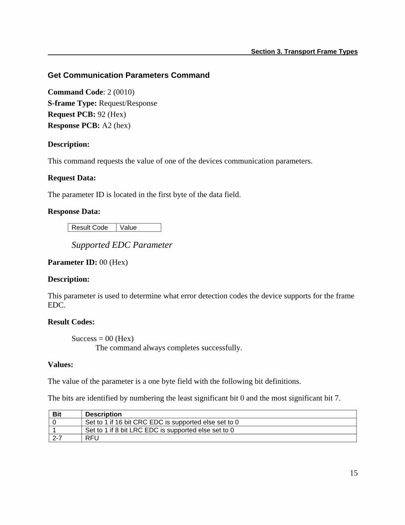
Get Communication Parameters Command Command Code: 2 (0010) S-frame Type: Request/Response Request PCB: 92 (Hex) Response PCB: A2 (hex) Description:
This command requests the value of one of the devices communication parameters. Request Data:
The parameter ID is located in the first byte of the data field. Response Data:
Result Code Value
Supported EDC Parameter Parameter ID: 00 (Hex) Description:
This parameter is used to determine what error detection codes the device supports for the frame EDC. Result Codes: Success = 00 (Hex)
The command always completes successfully. Values: The value of the parameter is a one byte field with the following bit definitions. The bits are identified by numbering the least significant bit 0 and the most significant bit 7.
Bit Description 0 Set to 1 if 16 bit CRC EDC is supported else set to 0 1 Set to 1 if 8 bit LRC EDC is supported else set to 0 2-7 RFU
MCP Serial Transport Protocol
16
Model Number Parameter Parameter ID: 01 (Hex) Description:
This parameter is not supported.
Serial Number Parameter Parameter ID: 02 (Hex) Description:
This parameter is not supported.
Application Message Maximum Response Time Parameter ID: 03 (Hex) Description:
This parameter is not supported.
Block Wait Timeout (BWT) Parameter Parameter ID: 04 (Hex) Description:
This parameter is used to determine what block wait timeout value the device is using. Result Codes: Success = 00 (Hex)
The command always completes successfully. Values: The value of this parameter is a one byte field that can be in the range of 25 to 250. The actual value of the block wait timeout is the value of this field multiplied by 10ms. For example, if the value of this field is 25 (19 hex) the block wait timeout is 25 times 10ms which equals 250ms. This parameter defaults to a value of 25 (250ms) after a power cycle or a reset.
Section 3. Transport Frame Types
17
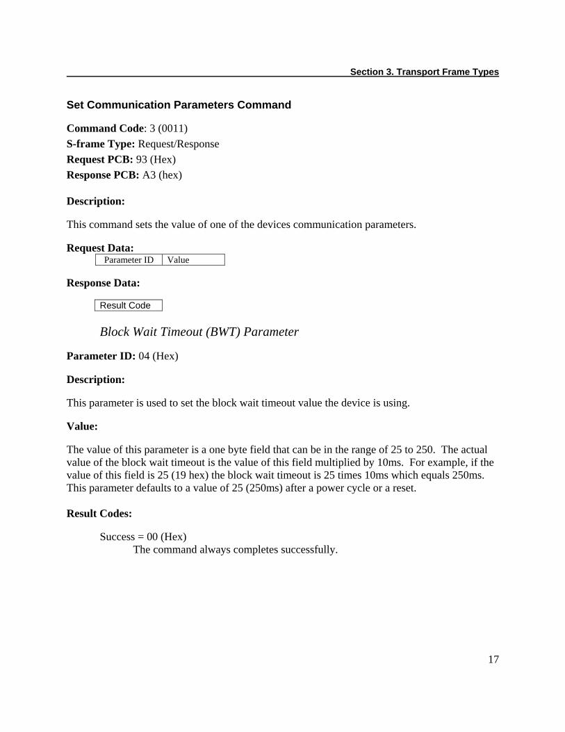
Set Communication Parameters Command Command Code: 3 (0011) S-frame Type: Request/Response Request PCB: 93 (Hex) Response PCB: A3 (hex) Description:
This command sets the value of one of the devices communication parameters. Request Data:
Parameter ID Value
Response Data:
Result Code
Block Wait Timeout (BWT) Parameter Parameter ID: 04 (Hex) Description:
This parameter is used to set the block wait timeout value the device is using. Value: The value of this parameter is a one byte field that can be in the range of 25 to 250. The actual value of the block wait timeout is the value of this field multiplied by 10ms. For example, if the value of this field is 25 (19 hex) the block wait timeout is 25 times 10ms which equals 250ms. This parameter defaults to a value of 25 (250ms) after a power cycle or a reset. Result Codes: Success = 00 (Hex)
The command always completes successfully.

MCP Serial Transport Protocol
18
Frame Reject Command Command Code: 5 (0101) S-frame Type: Indication PCB: 85 (Hex) Description: The frame reject command is used to notify another node on the network that a frame they sent was not valid (e.g. unsupported EDC type). Frame rejection is used on frames that are understood by the receiver but contain unsupported types or data. For example, the frame may specify an unsupported frame type or may contain an invalid status code. In this case the frame passed error detection validation and was received correctly but contained invalid data. The frame reject command is an indication. It does not require a response from the recipient. If a node decides to respond to the indication, it must send a frame different than the frame previously sent. The use of the command is optional. The command’s sole purpose is to speed up error recovery.
Data:
The structure of the data field of this indication is defined as follows:
PCB ETYP • PCB PCB field of the invalid frame • ETYP type of error detected (unsupported frame type, unsupported EDC type, …)
The type of error can be one of the following:
ETYP Definition
0 Unsupported frame type. 1 Unsupported S-frame command. 2 Chaining not supported. 3 Frame is too long. 4 Message is too long. 5 EDC type error. 6 Communication error on the bus. 7 Abort chain.

Section 3. Transport Frame Types
19
Baud Synchronization Command Command Code: 6 (0110) S-frame Type: Request/Response Request PCB: 96 (Hex) Response PCB: A6 (hex) Description: This command is used by the host to synchronize the transmission speed on mediums with variable communication speed (i.e., serial ports). A response indicates that the device is synchronized with the transport. If the device synchronizes, it will take no longer than 75ms to respond to this request. If the device does not synchronize, no response will be sent. The device requires up to 2.5 seconds to lock onto a baud rate; therefore the transport should continue sending the baud sync request for that period of time. The transport must send the request at intervals 75-125ms (100ms optimal) until the transport and device are synchronized. The device will respond to this command as soon as it is synchronized with the baud rate which means that the device could possibly respond before the 2.5 second time period is up. The host can stop sending the baud sync command when the device responds. A device that requires baud synchronization will not respond to any frame until it has synchronized. A device that requires baud synchronization will require synchronization after power on or a reset. In order to communicate at a different baud rate than the device has been synchronized to, the device will need to be power cycled or reset then the baud synchronization process will have to be repeated with the new baud rate. When a device is waiting to be synchronized, it cycles through its list of synchronizable baud rates enabling reception at each rate for a period of about 300ms. It continuously repeats the cycle within 2.5 seconds until it is synchronized.
Request Data: The structure of the data field of this request consists of the two hex bytes “MT” ASCII which stands for MagTek:
4D (Hex) 54 (Hex)
Response Data:
Result Code
Result Codes: Success = 00 (Hex) This command will always succeed if synchronized or else it will get no response.
MCP Serial Transport Protocol
20
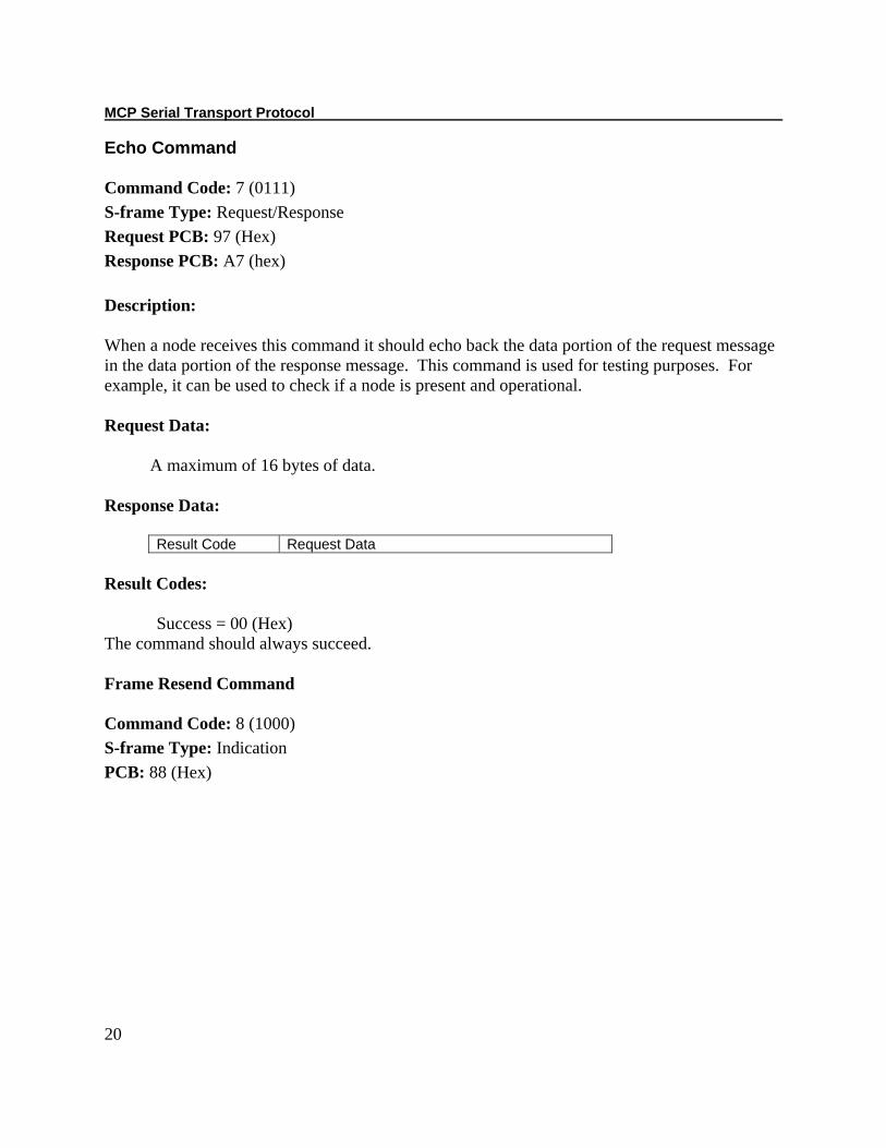
Echo Command Command Code: 7 (0111) S-frame Type: Request/Response Request PCB: 97 (Hex) Response PCB: A7 (hex) Description: When a node receives this command it should echo back the data portion of the request message in the data portion of the response message. This command is used for testing purposes. For example, it can be used to check if a node is present and operational.
Request Data: A maximum of 16 bytes of data. Response Data:
Result Code Request Data
Result Codes: Success = 00 (Hex) The command should always succeed. Frame Resend Command Command Code: 8 (1000) S-frame Type: Indication PCB: 88 (Hex)
Section 3. Transport Frame Types
21
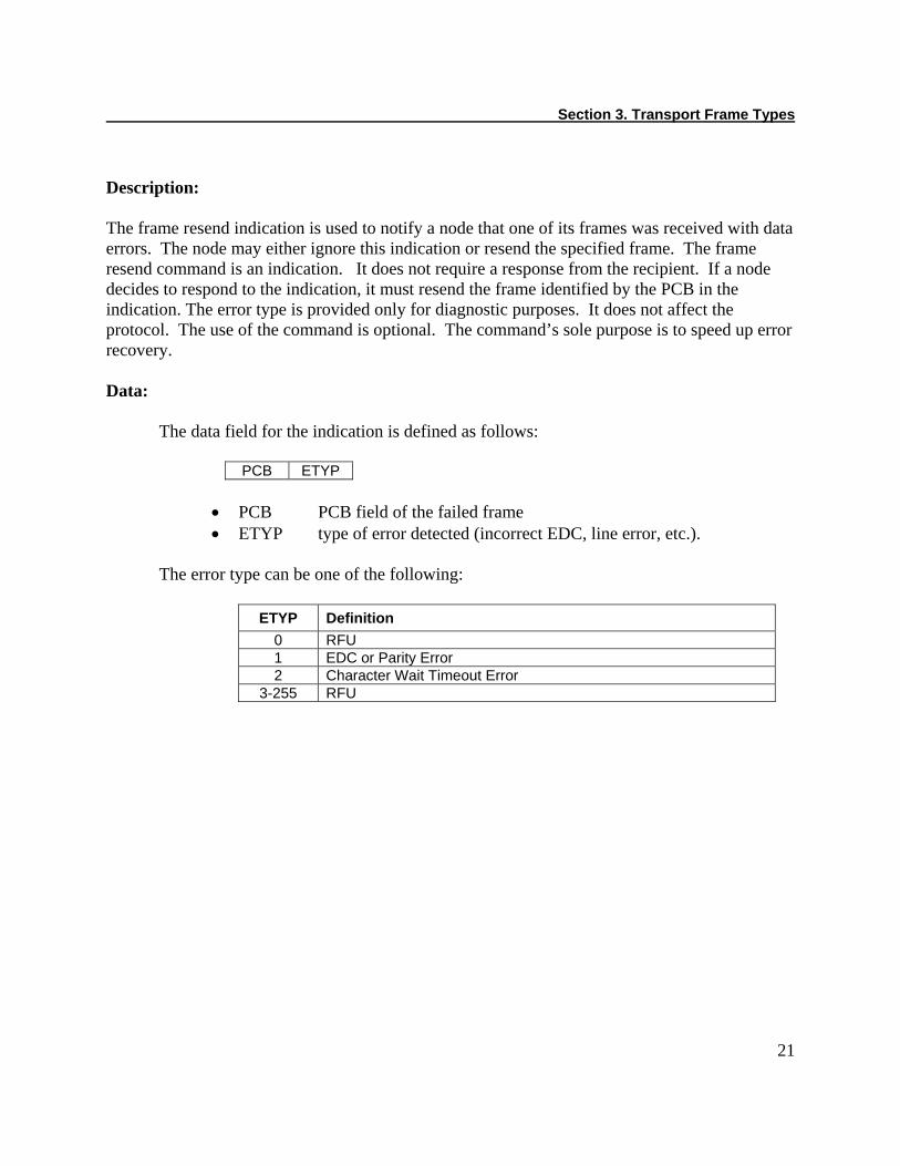
Description: The frame resend indication is used to notify a node that one of its frames was received with data errors. The node may either ignore this indication or resend the specified frame. The frame resend command is an indication. It does not require a response from the recipient. If a node decides to respond to the indication, it must resend the frame identified by the PCB in the indication. The error type is provided only for diagnostic purposes. It does not affect the protocol. The use of the command is optional. The command’s sole purpose is to speed up error recovery. Data:
The data field for the indication is defined as follows:
PCB ETYP
• PCB PCB field of the failed frame • ETYP type of error detected (incorrect EDC, line error, etc.).
The error type can be one of the following:
ETYP Definition 0 RFU 1 EDC or Parity Error 2 Character Wait Timeout Error
3-255 RFU


23
SECTION 4. PROTOCOL This section describes the protocol used for nodes to communicate using the frame formats and S-frame command described previously. PARAMETERS After two nodes are synchronized and before they begin exchanging frames, the nodes must retrieve any required communication parameters from each other. The Supported EDC Type parameter is an example of a parameter that may be desired. For a complete list of the supported parameters, see the S-frame Get Communication Parameters command. TIMEOUTS This section defines the three types of timeouts a node uses. Character Wait Timeout (CWT) This timeout is used by the node receiving a frame. This timeout is the maximum period of time allowed between characters of a frame being received. The period is measured from the time a character is received to the time the next character is received. The purpose of this timeout is to provide an end of frame indicator for damaged frames that are being received. Under error free conditions, the expected number of bytes in a frame can be determined by the information in the PCB and the length fields of the frame. The end of a frame can be determined by counting the bytes received and comparing the count to the expected number of bytes in the frame. When there is an error in the frame the CWT ensures that the end of the frame is detected. The CWT should not be used to detect the end of frames under error free conditions because it would slow down the protocol. Devices will use a minimum CWT value of 10ms.
Block Wait Timeout (BWT) This timeout is used by the node transmitting a frame. This timeout is the maximum period of time allowed between transmitting a frame and receiving a frame that acknowledges the transmitted frame. Not all frames require an acknowledgement frame. The period is measured from the time the last character of a frame is transmitted to the time an acknowledgement frame is received. If the time expires while receiving a frame, then the timeout will be extended until the entire frame is received and processed. If this timeout expires, the transmitting node should initiate error recovery. Devices will use a minimum BWT value of 250ms. See the S-frame sections get communications parameter and set communication parameters command for information on how to get and set the value of BWT.
MCP Serial Transport Protocol
24
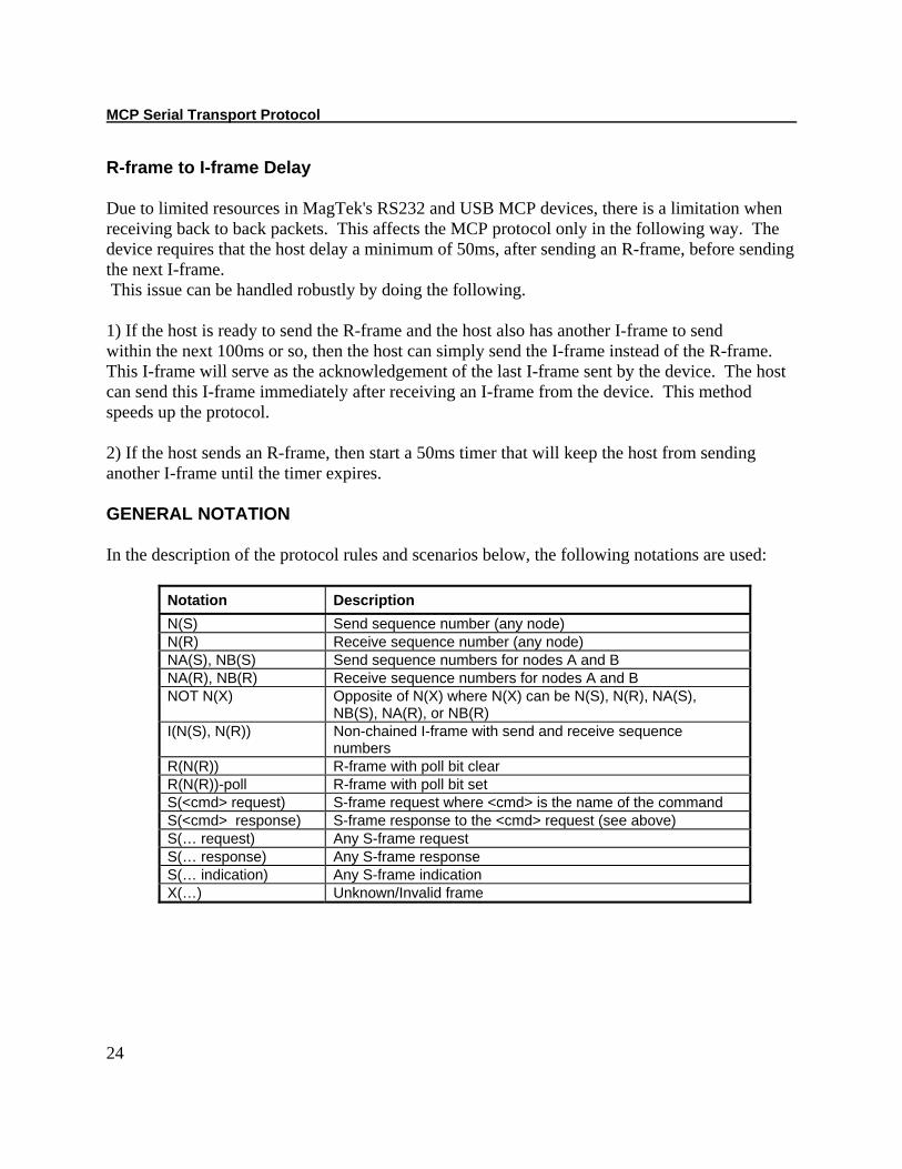
R-frame to I-frame Delay Due to limited resources in MagTek's RS232 and USB MCP devices, there is a limitation when receiving back to back packets. This affects the MCP protocol only in the following way. The device requires that the host delay a minimum of 50ms, after sending an R-frame, before sending the next I-frame. This issue can be handled robustly by doing the following. 1) If the host is ready to send the R-frame and the host also has another I-frame to send within the next 100ms or so, then the host can simply send the I-frame instead of the R-frame. This I-frame will serve as the acknowledgement of the last I-frame sent by the device. The host can send this I-frame immediately after receiving an I-frame from the device. This method speeds up the protocol. 2) If the host sends an R-frame, then start a 50ms timer that will keep the host from sending another I-frame until the timer expires. GENERAL NOTATION In the description of the protocol rules and scenarios below, the following notations are used:
Notation Description N(S) Send sequence number (any node) N(R) Receive sequence number (any node) NA(S), NB(S) Send sequence numbers for nodes A and B NA(R), NB(R) Receive sequence numbers for nodes A and B NOT N(X) Opposite of N(X) where N(X) can be N(S), N(R), NA(S),
NB(S), NA(R), or NB(R) I(N(S), N(R)) Non-chained I-frame with send and receive sequence
numbers R(N(R)) R-frame with poll bit clear R(N(R))-poll R-frame with poll bit set S(<cmd> request) S-frame request where <cmd> is the name of the command S(<cmd> response) S-frame response to the <cmd> request (see above) S(… request) Any S-frame request S(… response) Any S-frame response S(… indication) Any S-frame indication X(…) Unknown/Invalid frame

Section 4. Protocol
25
GENERAL PROCEDURES During the protocol, any node may send a frame at any time, regardless of whether it has received a frame or not. The frame may either be an I-frame, R-frame or S-frame. Every I-frame carries its send sequence number (N(S)). The I-frames sent by any two nodes are counted independently of each other. N(S) is counted modulo 2 and is coded by one bit. At the start of the protocol or after resynchronization, the initial value is N(S) = 0; then the value alternates after sending each I-frame. Every I-frame and R-frame carries N(R) which is the send sequence number N(S) of the next expected I-frame. I-frames and R-frames are used to acknowledge that a frame has been received and indicates readiness to receive the next frame. A sent I-frame is acknowledged by receiving:
• either an I-frame where N(R) is different than N(S) of the previously received I-frame • or an R-frame where N(R) is different than N(S) of the sent I-frame
S-frames carry no sequence numbers; an S-frame request (S(… request)) is acknowledged by receiving an S-frame response (S(… response)). ERROR HANDLING The transport layer should be able to handle the following errors:
• Block Wait Timeout (BWT) • Character Wait Timeout (CWT) • Reception of a damaged frame due to an EDC error • Reception of an invalid frame, examples are: unsupported EDC type, unsupported
frame type, etc.
MCP Serial Transport Protocol
26
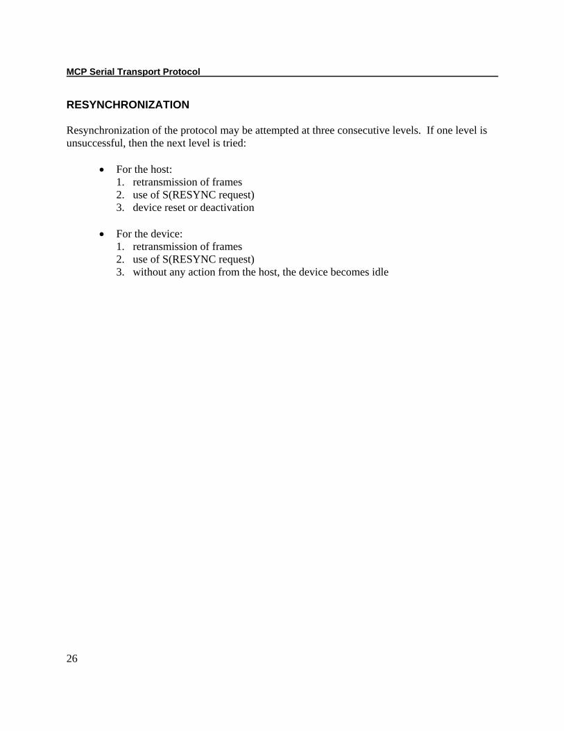
RESYNCHRONIZATION Resynchronization of the protocol may be attempted at three consecutive levels. If one level is unsuccessful, then the next level is tried:
• For the host: 1. retransmission of frames 2. use of S(RESYNC request) 3. device reset or deactivation
• For the device:
1. retransmission of frames 2. use of S(RESYNC request) 3. without any action from the host, the device becomes idle

Section 4. Protocol
27
RULES Service Requests
Rule 1.1 A node can send a service request (S-frame request) at any time. The node shall not send another service request until it receives the service response or the block wait timeout expires.
Rule 1.2 A node that receives an S-frame request shall respond with an S-frame response. If the node does not recognize the command ID or any of the parameters, the response shall contain the “not supported” result code.
Rule 1.3 All nodes shall recognize RESYNC and ECHO S-frame requests.
Rule 1.4 A node that sends an S-frame request and does not receive the corresponding response within the block wait timeout shall either (a) resend the request according to Rule 1.1, or (b) give up. Baud Synchronization
Rule 2.1 A node can send a BAUD_SYNC request at any time when S-frame requests are allowed according to Rule 1.1. The baud synchronization request shall contain data that allows areceiving node to determine the line communication parameters without ambiguity (for RS-232, the data is “MT”)
Rule 2.2 A node that receives a BAUD_SYNC request without error shall respond with BAUD_SYNC response with response code “success”.

MCP Serial Transport Protocol
28
Rule 2.3 A node that sends a BAUD_SYNC request shall continue sending BAUD_SYNC requests until (a) it receives a valid response or (b) 2.5 seconds expire, whichever occurs first. The requests shall be sent 75-125 milliseconds apart. Establishing and Resetting a Connection
Rule 3.1 Nodes shall establish connection prior to exchanging user data. Only one connection may exist between any two nodes.
Rule 3.2 A node can initiate a connection by sending a RESYNC S-frame request in compliance with Rule 1.1. The node shall reset its send and receive sequence numbers prior to sending the request. It shall ignore any incoming I-frames and R-frames until it receives a valid RESYNC S-frame response with result code “success”. The node can retry the RESYNC request according to Rule 1.3.
Rule 3.3 A node that receives a RESYNC request may accept the connection by sending RESYNC response with result code “success”. The node shall reset its send and receive sequence numbers prior to sending the response.
Rule 3.4 Once a connection is established the nodes can exchange user data in both directions, regardless of which node initiated the connection.
Rule 3.5 There is no direct way to dissolve a connection. If a node fails to send user data according to the data transfer and error recovery rules below, it shall assume the connection dissolved.
Rule 3.6 A node can initiate resetting the connection by sending RESYNC request according to Rule 3.2. Any outstanding unconfirmed I-frames shall be considered not transmitted successfully before the RESYNC request is sent.
Section 4. Protocol
29
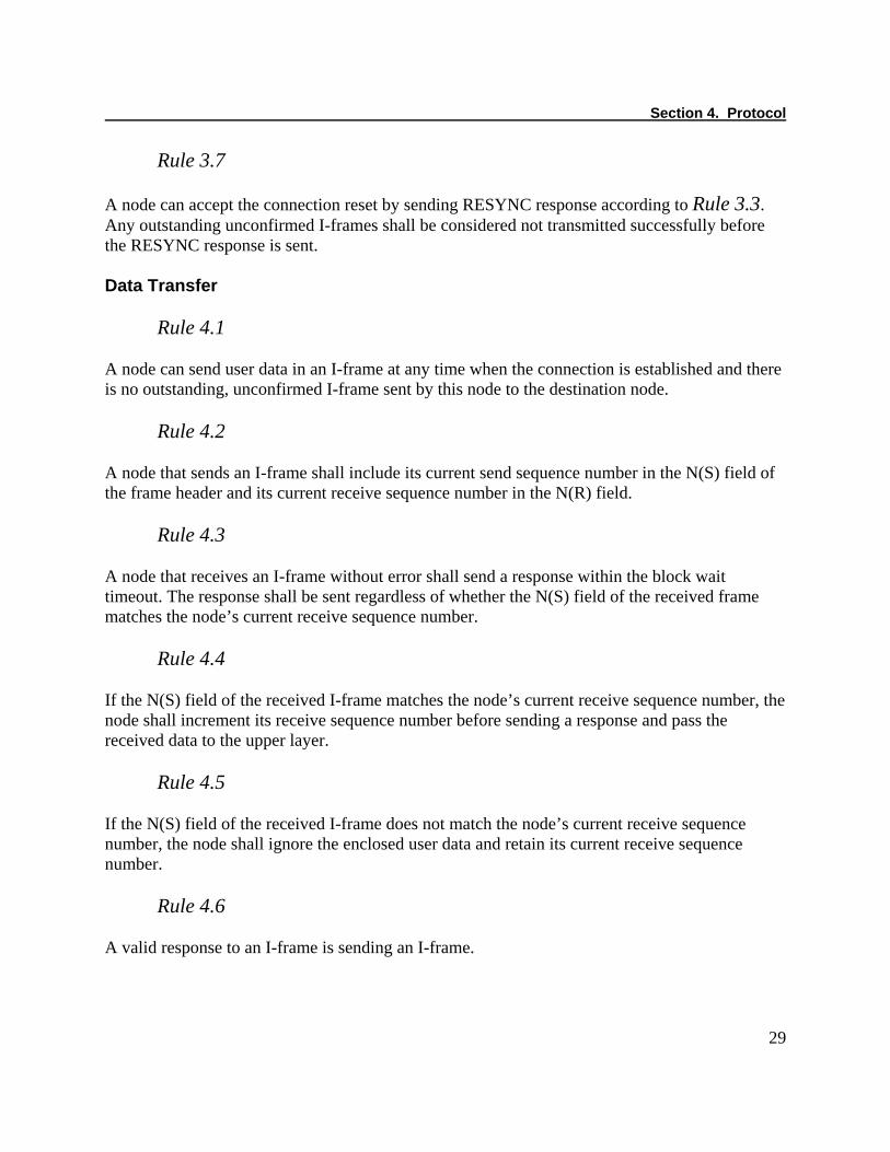
Rule 3.7 A node can accept the connection reset by sending RESYNC response according to Rule 3.3. Any outstanding unconfirmed I-frames shall be considered not transmitted successfully before the RESYNC response is sent. Data Transfer
Rule 4.1 A node can send user data in an I-frame at any time when the connection is established and there is no outstanding, unconfirmed I-frame sent by this node to the destination node.
Rule 4.2 A node that sends an I-frame shall include its current send sequence number in the N(S) field of the frame header and its current receive sequence number in the N(R) field.
Rule 4.3 A node that receives an I-frame without error shall send a response within the block wait timeout. The response shall be sent regardless of whether the N(S) field of the received frame matches the node’s current receive sequence number.
Rule 4.4 If the N(S) field of the received I-frame matches the node’s current receive sequence number, the node shall increment its receive sequence number before sending a response and pass the received data to the upper layer.
Rule 4.5 If the N(S) field of the received I-frame does not match the node’s current receive sequence number, the node shall ignore the enclosed user data and retain its current receive sequence number.
Rule 4.6 A valid response to an I-frame is sending an I-frame.

MCP Serial Transport Protocol
30
Rule 4.7 A valid response to an I-frame is sending an R-frame with node’s current receive sequence number in the frame’s N(R) field.
Rule 4.8 When a node that is awaiting response to its I-frame receives a valid response that contains N(R) field that is equal to the node’s send sequence number plus one, the node shall increment its send sequence number and consider the user data successfully transferred.
Rule 4.9 An I-frame sent by the node is considered outstanding until (a) the node receives a valid response according to Rule 4.8, (b) block wait timeout expires, or (c) the node sends RESYNC request or response. Error Recovery
Rule 5.1 When a node sends an I-frame and does not receive the response defined in Rule 4.8 within the block wait timeout, the node shall initiate error recovery.
Rule 5.2 A node can initiate error recovery by sending an R-frame with poll indicator set. The R-frame shall contain the node’s current receive sequence number in the N(R) field of the frame header.
Rule 5.3
A node can initiate error recovery by re-sending the I-frame for which it is expecting response. The I-frame shall be sent with the same N(S) as the original I-frame and with N(R) equal to the node’s current receive sequence number, which may have changed since the original I-frame was sent.
Rule 5.4 A node that receives R-frame with poll indicator set shall, in addition to its normal processing of the R-frame, respond either (a) with R-frame as per Rule 4.7, or (b) with I-frame as per Rule 4.6.

Section 4. Protocol
31
Rule 5.5 A node that initiated error recovery per Rule 5.2 (using R-frame with poll bit set) processes the next received R-frame or I-frame the following way: (a) if the N(R) field of the received frame is equal to the node’s last sent N(S) plus one, then the node accepts this as confirmation according to Rule 4.8; otherwise (b), it re-sends the outstanding I-frame and again starts waiting for the response. In case (b), the node sends the I-frame with the same N(S) as the original I-frame and with N(R) equal to the node’s current receive sequence number, which may have changed since the original I-frame was sent.
Rule 5.6 If a node that initiated error recovery per Rule 5.2 does not receive either an I-frame or an R-frame within the block wait timeout, the node shall (a) re-send the R-frame with poll indicator set using its current receive sequence number or (b) give up.
Rule 5.7 If a node that initiated error recovery per Rule 5.3 does not receive the expected response within the block wait timeout, the node shall (a) re-send the I-frame per Rule 5.3 or (b) give up.
Rule 5.8 If a node gives up on error recovery per Rule 5.6 or Rule 5.7 it shall consider the user dataunsent. The node shall (a) consider the connection dissolved and stop sending and receiving user data until it receives RESYNC request per
Rule 3.2 and Error! Reference source not found.,
(b) initiate connection reset per Rule 3.6, or (c) initiate baud synchronization per Rule 2.2followed by connection reset per rule Rule 3.6. Service Indications
Rule 6.1 If a node receives a frame with correct header EDC but incorrect full EDC, the node shall either (a) ignore the frame or (b) send a RESEND S-frame indication enclosing the PCB byte from the received frame and specifying the “EDC error” error code.
MCP Serial Transport Protocol
32
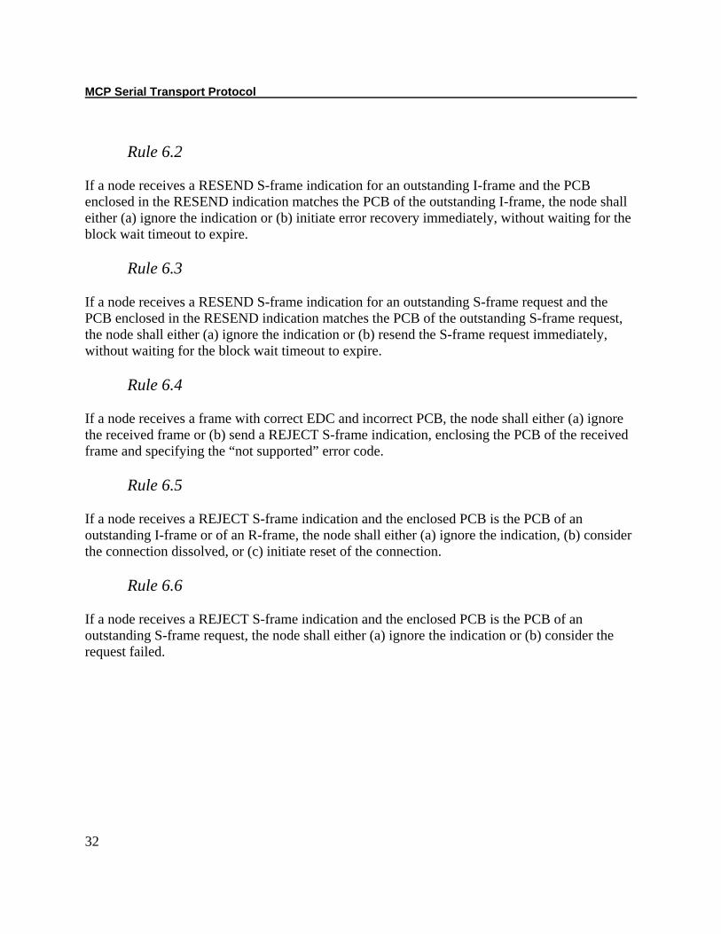
Rule 6.2
If a node receives a RESEND S-frame indication for an outstanding I-frame and the PCB enclosed in the RESEND indication matches the PCB of the outstanding I-frame, the node shall either (a) ignore the indication or (b) initiate error recovery immediately, without waiting for the block wait timeout to expire.
Rule 6.3 If a node receives a RESEND S-frame indication for an outstanding S-frame request and the PCB enclosed in the RESEND indication matches the PCB of the outstanding S-frame request, the node shall either (a) ignore the indication or (b) resend the S-frame request immediately, without waiting for the block wait timeout to expire.
Rule 6.4 If a node receives a frame with correct EDC and incorrect PCB, the node shall either (a) ignore the received frame or (b) send a REJECT S-frame indication, enclosing the PCB of the received frame and specifying the “not supported” error code.
Rule 6.5 If a node receives a REJECT S-frame indication and the enclosed PCB is the PCB of an outstanding I-frame or of an R-frame, the node shall either (a) ignore the indication, (b) consider the connection dissolved, or (c) initiate reset of the connection.
Rule 6.6 If a node receives a REJECT S-frame indication and the enclosed PCB is the PCB of an outstanding S-frame request, the node shall either (a) ignore the indication or (b) consider the request failed.
Section 4. Protocol
33
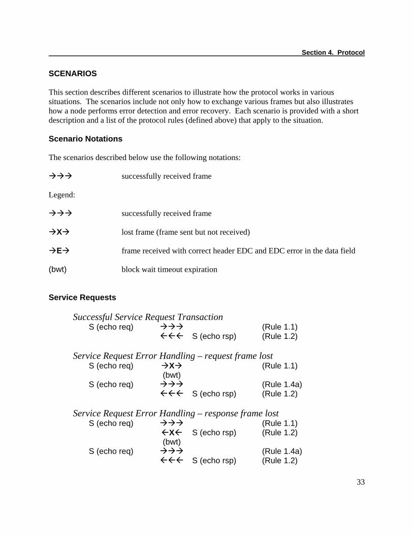
SCENARIOS This section describes different scenarios to illustrate how the protocol works in various situations. The scenarios include not only how to exchange various frames but also illustrates how a node performs error detection and error recovery. Each scenario is provided with a short description and a list of the protocol rules (defined above) that apply to the situation. Scenario Notations The scenarios described below use the following notations:
successfully received frame Legend:
successfully received frame
X lost frame (frame sent but not received)
E frame received with correct header EDC and EDC error in the data field (bwt) block wait timeout expiration Service Requests
Successful Service Request Transaction S (echo req) (Rule 1.1) S (echo rsp) (Rule 1.2)
Service Request Error Handling – request frame lost
S (echo req) X (Rule 1.1) (bwt) S (echo req) (Rule 1.4a) S (echo rsp) (Rule 1.2)
Service Request Error Handling – response frame lost
S (echo req) (Rule 1.1) X S (echo rsp) (Rule 1.2) (bwt) S (echo req) (Rule 1.4a) S (echo rsp) (Rule 1.2)
MCP Serial Transport Protocol
34
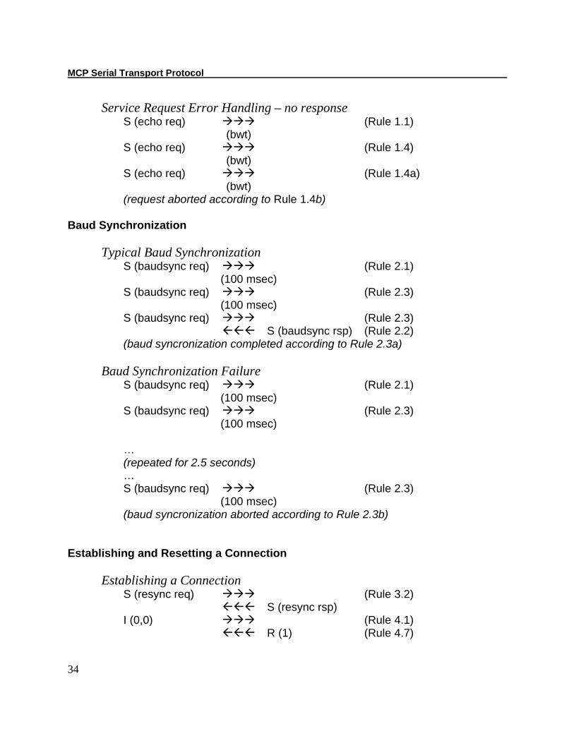
Service Request Error Handling – no response S (echo req) (Rule 1.1) (bwt) S (echo req) (Rule 1.4) (bwt) S (echo req) (Rule 1.4a) (bwt) (request aborted according to Rule 1.4b)
Baud Synchronization
Typical Baud Synchronization S (baudsync req) (Rule 2.1) (100 msec) S (baudsync req) (Rule 2.3) (100 msec) S (baudsync req) (Rule 2.3) S (baudsync rsp) (Rule 2.2) (baud syncronization completed according to Rule 2.3a)
Baud Synchronization Failure
S (baudsync req) (Rule 2.1) (100 msec) S (baudsync req) (Rule 2.3) (100 msec)
… (repeated for 2.5 seconds) … S (baudsync req) (Rule 2.3) (100 msec) (baud syncronization aborted according to Rule 2.3b)
Establishing and Resetting a Connection
Establishing a Connection S (resync req) (Rule 3.2) S (resync rsp) I (0,0) (Rule 4.1) R (1) (Rule 4.7)
Section 4. Protocol
35
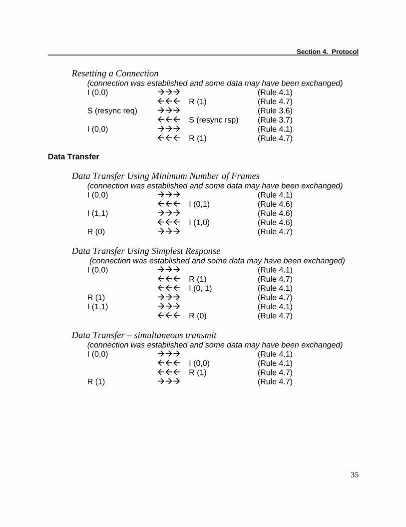
Resetting a Connection (connection was established and some data may have been exchanged) I (0,0) (Rule 4.1) R (1) (Rule 4.7) S (resync req) (Rule 3.6) S (resync rsp) (Rule 3.7) I (0,0) (Rule 4.1) R (1) (Rule 4.7)
Data Transfer
Data Transfer Using Minimum Number of Frames (connection was established and some data may have been exchanged) I (0,0) (Rule 4.1) I (0,1) (Rule 4.6) I (1,1) (Rule 4.6) I (1,0) (Rule 4.6) R (0) (Rule 4.7)
Data Transfer Using Simplest Response
(connection was established and some data may have been exchanged) I (0,0) (Rule 4.1) R (1) (Rule 4.7) I (0, 1) (Rule 4.1) R (1) (Rule 4.7) I (1,1) (Rule 4.1) R (0) (Rule 4.7)
Data Transfer – simultaneous transmit
(connection was established and some data may have been exchanged) I (0,0) (Rule 4.1) I (0,0) (Rule 4.1) R (1) (Rule 4.7) R (1) (Rule 4.7)
MCP Serial Transport Protocol
36
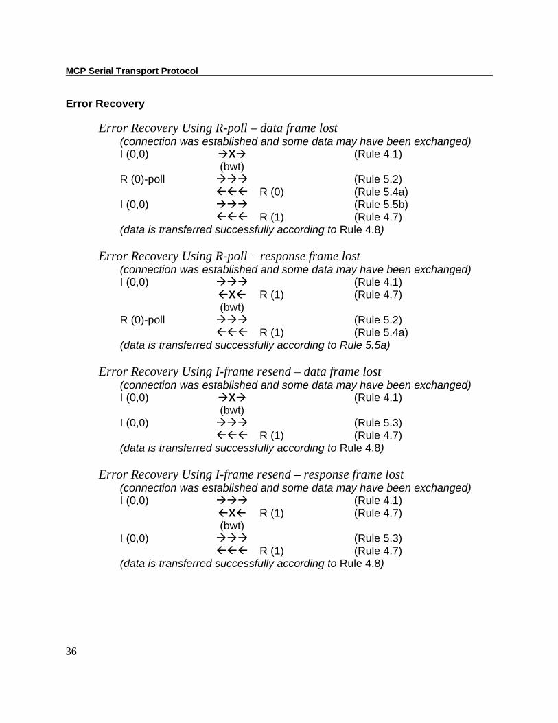
Error Recovery
Error Recovery Using R-poll – data frame lost (connection was established and some data may have been exchanged) I (0,0) X (Rule 4.1) (bwt) R (0)-poll (Rule 5.2) R (0) (Rule 5.4a) I (0,0) (Rule 5.5b) R (1) (Rule 4.7) (data is transferred successfully according to Rule 4.8)
Error Recovery Using R-poll – response frame lost
(connection was established and some data may have been exchanged) I (0,0) (Rule 4.1) X R (1) (Rule 4.7) (bwt) R (0)-poll (Rule 5.2) R (1) (Rule 5.4a) (data is transferred successfully according to Rule 5.5a)
Error Recovery Using I-frame resend – data frame lost
(connection was established and some data may have been exchanged) I (0,0) X (Rule 4.1) (bwt) I (0,0) (Rule 5.3) R (1) (Rule 4.7) (data is transferred successfully according to Rule 4.8)
Error Recovery Using I-frame resend – response frame lost
(connection was established and some data may have been exchanged) I (0,0) (Rule 4.1) X R (1) (Rule 4.7) (bwt) I (0,0) (Rule 5.3) R (1) (Rule 4.7) (data is transferred successfully according to Rule 4.8)

Section 4. Protocol
37
Error Recovery – intermediate data received (connection was established and some data may have been exchanged) I (0,0) X (Rule 4.1) I (0,0) (Rule 4.1) R (1) (Rule 4.7) (bwt) (bwt from the first I-frame) R (1)-poll (Rule 5.2) R (0) (Rule 5.4a) I (0,1) (Rule 5.5b) R (1) (Rule 4.7) (data is transferred successfully according to Rule 4.8)
Assuming Disconnected State Upon Failure of Error Recovery
(connection was established and some data may have been exchanged) I (0,0) (Rule 4.1) (bwt) R (0)-poll (Rule 5.2) (bwt) R (0)-poll (Rule 5.6a) (bwt) R (0)-poll (Rule 5.6a) (bwt) (data transfer failed according to Rule 5.6b) (sending node assumes the connection to be dissolved according to Rule 5.8a)
Resetting Connection Upon Failure of Error Recovery
(connection was established and some data may have been exchanged) I (0,0) (Rule 4.1) (bwt) R (0)-poll (Rule 5.2) (bwt) R (0)-poll (Rule 5.6a) (bwt) R (0)-poll (Rule 5.6a) (bwt) (data transfer fails according to Rule 5.6b) S (resync req) (Rule 5.8b and Rule 3.6) S (resync rsp) (Rule 3.7) I (0,0) (Rule 4.1) (new request) R (1) (Rule 4.7)
MCP Serial Transport Protocol
38
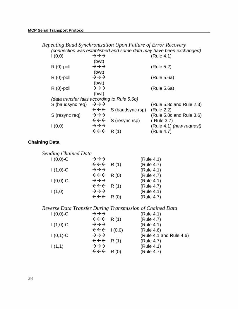
Repeating Baud Synchronization Upon Failure of Error Recovery (connection was established and some data may have been exchanged) I (0,0) (Rule 4.1) (bwt) R (0)-poll (Rule 5.2) (bwt) R (0)-poll (Rule 5.6a) (bwt) R (0)-poll (Rule 5.6a) (bwt) (data transfer fails according to Rule 5.6b) S (baudsync req) (Rule 5.8c and Rule 2.3) S (baudsync rsp) (Rule 2.2) S (resync req) (Rule 5.8c and Rule 3.6) S (resync rsp) ( Rule 3.7) I (0,0) (Rule 4.1) (new request) R (1) (Rule 4.7)
Chaining Data
Sending Chained Data I (0,0)-C (Rule 4.1) R (1) (Rule 4.7) I (1,0)-C (Rule 4.1) R (0) (Rule 4.7) I (0,0)-C (Rule 4.1) R (1) (Rule 4.7) I (1,0) (Rule 4.1) R (0) (Rule 4.7)
Reverse Data Transfer During Transmission of Chained Data
I (0,0)-C (Rule 4.1) R (1) (Rule 4.7) I (1,0)-C (Rule 4.1) I (0,0) (Rule 4.6) I (0,1)-C (Rule 4.1 and Rule 4.6) R (1) (Rule 4.7) I (1,1) (Rule 4.1) R (0) (Rule 4.7)
Section 4. Protocol
39
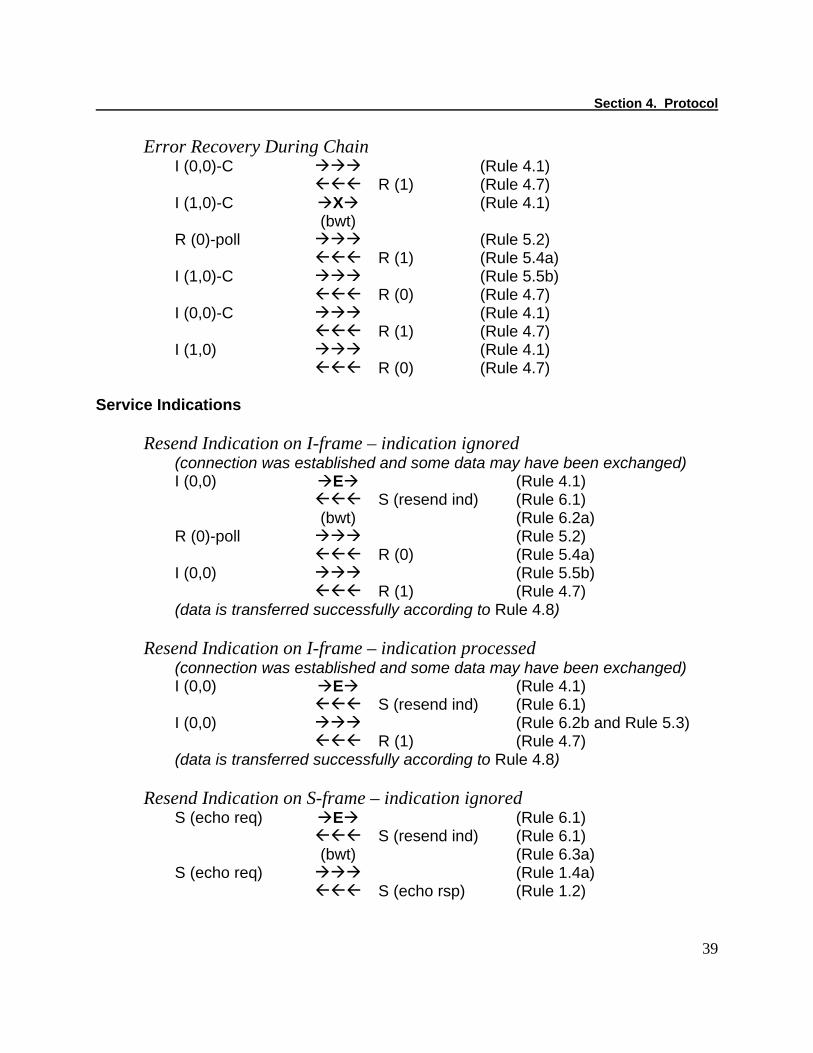
Error Recovery During Chain I (0,0)-C (Rule 4.1) R (1) (Rule 4.7) I (1,0)-C X (Rule 4.1) (bwt) R (0)-poll (Rule 5.2) R (1) (Rule 5.4a) I (1,0)-C (Rule 5.5b) R (0) (Rule 4.7) I (0,0)-C (Rule 4.1) R (1) (Rule 4.7) I (1,0) (Rule 4.1) R (0) (Rule 4.7)
Service Indications
Resend Indication on I-frame – indication ignored (connection was established and some data may have been exchanged) I (0,0) E (Rule 4.1) S (resend ind) (Rule 6.1) (bwt) (Rule 6.2a) R (0)-poll (Rule 5.2) R (0) (Rule 5.4a) I (0,0) (Rule 5.5b) R (1) (Rule 4.7) (data is transferred successfully according to Rule 4.8)
Resend Indication on I-frame – indication processed
(connection was established and some data may have been exchanged) I (0,0) E (Rule 4.1) S (resend ind) (Rule 6.1) I (0,0) (Rule 6.2b and Rule 5.3) R (1) (Rule 4.7) (data is transferred successfully according to Rule 4.8)
Resend Indication on S-frame – indication ignored
S (echo req) E (Rule 6.1) S (resend ind) (Rule 6.1) (bwt) (Rule 6.3a) S (echo req) (Rule 1.4a) S (echo rsp) (Rule 1.2)

MCP Serial Transport Protocol
40
Resend Indication on S-frame – indication processed S (echo req) E (Rule 1.1) S (resend ind) (Rule 6.1) S (echo req) (Rule 6.3b and Rule 1.4a) X S (echo rsp) (Rule 1.2) (bwt) S (echo req) (Rule 1.4a) S (echo rsp) (Rule 1.2)
41
SECTION 5. USB
This protocol can work as is with a RS-232 interface. However, the protocol needs to be adapted slightly to work with a USB interface. This section explains how to adapt this protocol to work with a USB interface. Everything mentioned in the preceding sections apply to the USB interface except what is pointed out in this section. The serial transport protocol is effectively “tunneled” over the USB. The baud synchronization S-frame command is not used with USB. The character wait timeout is handled slightly differently. The period is measured from the time a USB packet is received to the time the next USB packet is received. Devices will use a minimum CWT value of 100ms. The device shall support Full speed USB. The protocol will be implemented on the following three pipes. The device shall contain 1 bulk out pipe. The host shall use this pipe to transmit frames. The device shall use this pipe to receive frames. The device shall contain 1 bulk in pipe. The host shall use this pipe to receive frames. The device shall use this pipe to transmit frames. The device shall contain 1 interrupt in pipe. The host shall poll this pipe periodically to determine if the device is ready to transmit a frame. The device shall transmit one null packet on this pipe when it is ready to transmit a frame otherwise it will send a NAK. After the host receives this null packet it shall read the frame from the bulk in pipe. The host should not try to read the frame from the bulk in pipe until it receives the null packet on the interrupt in pipe. The host shall use the polling interval specified in the devices interrupt in endpoint descriptor for the polling frequency for this pipe. Typically this interval will be 10ms but it may vary on some devices. Since different USB peripheral hardware has different endpoint number assignment limitations, the endpoint numbers that these pipes are assigned to could vary from device to device. These endpoint number assignments could even vary between different device revisions with the same model number. Therefore the host should use the transfer type and transfer direction to identify the proper pipes to use for this protocol and not the endpoint numbers. The host shall use the maximum packet size specified in the pipes endpoint descriptors. This size may vary from one device to another. All devices shall use vendor identifier 0x0801.

MCP Serial Transport Protocol
42
Each model device shall use a different product identifier. The product identifier can usually be found in the device’s technical reference manual. All devices shall contain a manufacturer string descriptor with a value of “MagTek”. All devices shall contain a product string descriptor with a value that contains the model of the device. The product string value can usually be found in the device’s technical reference manual. Some devices may contain a programmable serial number string descriptor. This serial number could be used to uniquely identify multiple devices with the same model number in the same system if their serial numbers are programmed to unique values. If this option is present, its functionality will usually be described in the device’s command reference manual.