mccb distribution panels - electrical solutions
TRANSCRIPT

QuiXtra™630 Ed. 02
Low Voltage Distribution Boardsup to 630A
GEIndustrial Solutions
GE imagination at work

A.1
Introduction, Applications and Benefi ts
Order codes
Technical data
Numerical index
QuiXtra™630
A
B
C
X
IntroductionA.2 AdvantagesA.4 ApplicationsA.5 Product descriptionA.7 Features and benefi tsA.8 Kit structure
A.10 Main technical characteristicsA.11 Range overview
Order codesB.2 EnclosuresB.4 How to orderB.7 Functional units
B.12 BusbarsB.16 Cover plates and accessoires
Technical dataC.1 General characteristicsC.2 Mechanical and electrical characteristicsC.3 EnclosureC.5 Door
Functional unitsC.6 Coupling
Corrosion protectionPainting / coatingDegree of protection
C.7 BusbarsC.8 Form of internal separation
Earthing conceptC.9 Verifi cation of acceptable temperature rise
C.10 Derating tablesC.15 Power lossesC.20 Heat dissipation tablesC.26 Dimensional drawingsC.27 Specifi cations for tender documentsC.28 Appendix: IEC 61.439 versus IEC 60.439 for assemblies up to 630A
X.1 Numerical index
QuiXtra™630 - Low Voltage Distribution Boards
A.2
QuiXtra™630In
trod
uctio
n
A
B
C
XSISIMM
PMM
PLLEEEEE
SSIMMPPL
EQU
ICK
UICK
QUIC
K
Low Voltage panel QuiXtra™630
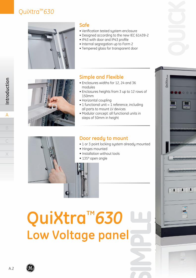
Safe • Verifi cation tested system enclosure• Designed according to the new IEC 61439-2• IP43 with door and IP43 profi le• Internal segregation up to Form 2• Tempered glass for transparent door
Simple and Flexible • Enclosures widths for 12, 24 and 36
modules • Enclosures heights from 3 up to 12 rows of
150mm • Horizontal coupling• 1 functional unit = 1 reference, including
all parts to mount LV devices• Modular concept: all functional units in
steps of 50mm in height
Door ready to mount • 1 or 3 point locking system already mounted• Hinges mounted• Installation without tools• 135º open angle
A.3
QuiXtra™630Advantages
A
B
C
X
PowerDesignv
GE
GE imagination at work
Design and Quotations softwarefor low voltage installations
Industrial Solutions
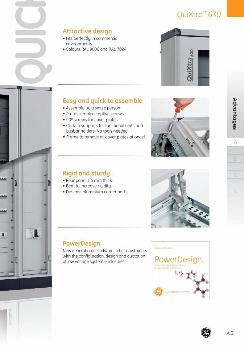
Easy and quick to assemble • Assembly by a single person• Pre-assembled captive screws• 90º screws for cover plates• Click-in supports for functional units and
busbar holders. No tools needed• Frame to remove all cover plates at once!
Rigid and sturdy• Rear panel 1.5 mm thick• Bent to increase rigidity• Die-cast aluminium corner parts
PowerDesign New generation of software to help customers with the confi guration, design and quotationof low voltage system enclosures
Attractive design • Fits perfectly in commercial
environments• Colours RAL 9006 and RAL 7024
QUIC
KQU
ICK
A.4
QuiXtra™630In
trod
uctio
n
A
B
C
X
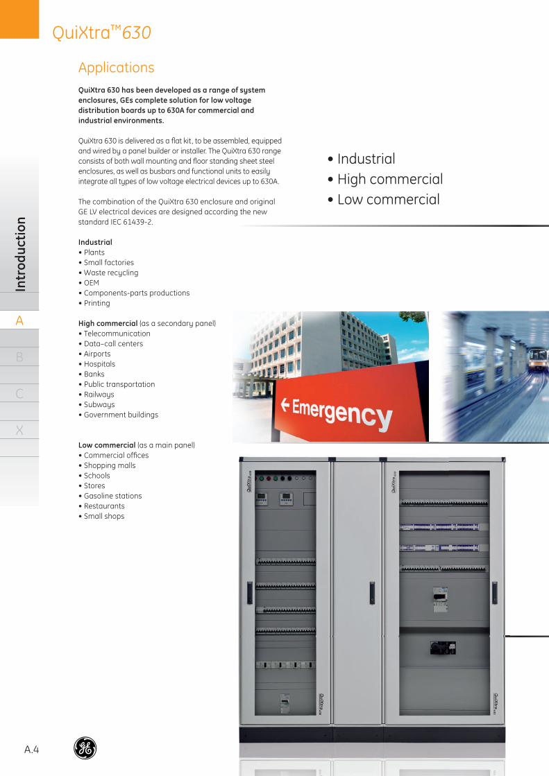
ApplicationsQuiXtra 630 has been developed as a range of system enclosures, GEs complete solution for low voltagedistribution boards up to 630A for commercial and industrial environments.
QuiXtra 630 is delivered as a fl at kit, to be assembled, equipped and wired by a panel builder or installer. The QuiXtra 630 range consists of both wall mounting and fl oor standing sheet steel enclosures, as well as busbars and functional units to easily integrate all types of low voltage electrical devices up to 630A.
The combination of the QuiXtra 630 enclosure and original GE LV electrical devices are designed according the new standard IEC 61439-2.
Industrial• Plants• Small factories• Waste recycling• OEM• Components-parts productions• Printing
High commercial (as a secondary panel)• Telecommunication• Data–call centers• Airports• Hospitals• Banks• Public transportation• Railways• Subways• Government buildings
Low commercial (as a main panel)• Commercial offi ces• Shopping malls• Schools• Stores• Gasoline stations• Restaurants• Small shops
• Industrial• High commercial• Low commercial
A.5
QuiXtra™630Product description
A
B
C
X
DescriptionQuiXtra 630 is a range of sheet steel system enclosures, delivered as a fl at kit. It is GEs solution for low voltage distribution boards up to 630A, in commercial and industrial environments.
QuiXtra 630 is designed to be a reliable, simple, fl exible and easy to use system enclosure, with the added value of its fresh and attractive design that integrates perfectly into a commercial environment.
The QuiXtra 630 range consists of 24 different enclosures. There are nine enclosure heights available, from 450mm up to 1800mm, and three enclosure widths, for functions of 12, 24 and 36 modules. All enclosures have the same depth (220mm without door and 250mm with door), allowing horizontal coupling and providing the user total fl exibility to defi ne the layout of the LV distribution boards.
A QuiXtra 630 system enclosure is assembled in 5 steps!
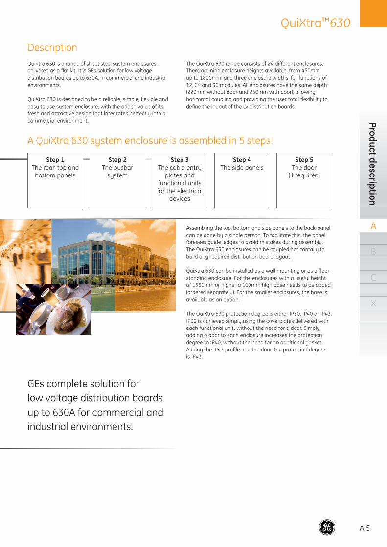
GEs complete solution for low voltage distribution boards up to 630A for commercial and industrial environments.
Assembling the top, bottom and side panels to the back-panelcan be done by a single person. To facilitate this, the panel foresees guide ledges to avoid mistakes during assembly.The QuiXtra 630 enclosures can be coupled horizontally to build any required distribution board layout.
QuiXtra 630 can be installed as a wall mounting or as a fl oor standing enclosure. For the enclosures with a useful height of 1350mm or higher a 100mm high base needs to be added (ordered separately). For the smaller enclosures, the base is available as an option.
The QuiXtra 630 protection degree is either IP30, IP40 or IP43. IP30 is achieved simply using the coverplates delivered with each functional unit , without the need for a door. Simply adding a door to each enclosure increases the protection degree to IP40, without the need for an additional gasket. Adding the IP43 profi le and the door, the protection degree is IP43.
Step 1The rear, top and
bottom panels
Step 2The busbar
system
Step 4The side panels
Step 5The door
(if required)
Step 3The cable entry
plates andfunctional units for the electrical
devices
A.6
QuiXtra™630In
trod
uctio
n
A
B
C
X
Description (continued)
QuiXtra 630 offers plain and transparent (tempered glass) doors, for an easy inspection of the devices installed inside the enclosure. The doors are equipped with a one or a three point closing mechanism (depending on the enclosure height), operated by a central handle. The handle is deliv-ered with a standard lock insert for key 2432E. The opening angle is 135 degrees. Attaching the doors to the enclosure is done without tools, using the simple pin-hinges. The doors are delivered with hinges and locking mechanism already mounted, to reduce assembly time.
All GE LV electrical devices up to 630A can be easily as-sembled in QuiXtra 630 using the appropriate functional units. Each functional unit kit includes everything necessary for assembly: • A mounting plate or DIN rail• A support to attach to the enclosure• A coverplate (with precise cut-outs) • The required screws and other fi xation parts. Attaching the mounting plates or DIN rails does not require tools: they are attached to the rear mounting profi le using a “click in” support. The coverplates are attached to two profi les using captive 90º screws. By removing these profi les, all cover plates can be removed at the same time.
QuiXtra 630 has suffi cient wiring space for any possible layout. Each side has room for a vertical 60mm cable-duct. The vertical and the horizontal cable-ducts can be integrated in different depths to suit the users’ needs. QuiXtra 630 offers a variety of different cable entry plates for the top and bottom panels, to assure enough space for the cable entry and to cover all type of panel installations.
For upgrades and maintenance, the end user has direct ac-cess to the vertical cable ducts of up to 40 mm (in each side of the functions) in an installed panel, simply by removing the coverplates. If wider space is required, it's necessary to disas-semble the side panels, which can be separately removed.
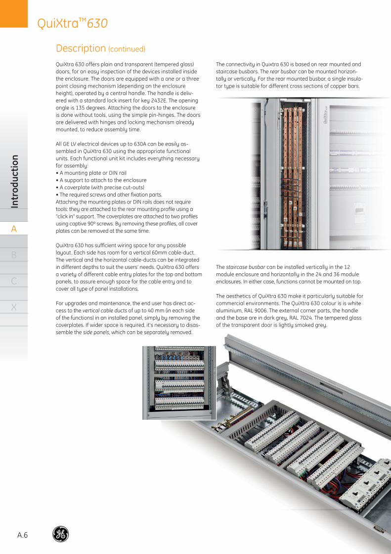
The connectivity in Quixtra 630 is based on rear mounted and staircase busbars. The rear busbar can be mounted horizon-tally or vertically. For the rear mounted busbar, a single insula-tor type is suitable for different cross sections of copper bars.
The staircase busbar can be installed vertically in the 12 module enclosure and horizontally in the 24 and 36 module enclosures. In either case, functions cannot be mounted on top.
The aesthetics of QuiXtra 630 make it particularly suitable for commercial environments. The QuiXtra 630 colour is is white aluminium, RAL 9006. The external corner parts, the handle and the base are in dark grey, RAL 7024. The tempered glass of the transparent door is lightly smoked grey.hehe
A.7
QuiXtra™630Features and Benefi ts
A
B
C
X
Features and Benefits
Simple and flexible• Enclosures widths for 12, 24 and 36 modules• Enclosures heights from 3 up to 12 rows of 150mm • Horizontal coupling of 2 or more enclosures• Modular concept. All functions in steps of 50mm in height• Functional kits for GE low voltage electrical devices up to 630A.
Mounting of GE devices in vertical or horizontal position• The busbars can be assembled in vertically or horizontally• Accessories to facilitate panel wiring and assembly • Each functional unit includes all parts necessary for assembly:
mounting plate or DIN rail, supporting brackets, cover plate (with precise cut-outs) and all required fi xation elements.
Easy and quick to assemble• Assembly by a single person• “Click in” supports for functions and busbar holders.
No tools needed • 90º screws for cover plates• Pre-assembled captive screws• Guiding ledges in back panel for top and side panel fi xation• Door assembly without tools. Doors delivered with locking system
and hinges pre-mounted (key 2432E)• Generous wiring space, enough for vertical cable ducts of 60mm
on each side• Frame allowing the removal of all cover plates at the same time• Markings in the fi xation profi les to quickly position the functional
units and cover plates• Pre-punched cable entry glands as option
Safe for users, reliable and sturdy• Verifi cation tested system enclosure, designed according to
the new IEC 61439-2 standard• IP43 with door, IP43 profi le, wall mounting supports and IP43 kit in the back• IP40 with door and without IP43 profi le• IP30 without door• Back panel galvanized sheet steel, 1.5mm• External panels sheet steel, 1.25mm, power coated• Aluminium corner parts provide additional rigidity to both
stand-alone and coupled enclosures• Internal segregation: Form 2• Tempered glass for the transparent door
Attractive design• Optimal integration in commercial environments• Combination of two colours:
RAL 9006 (metallic silver) andRAL 7024 (dark grey)
A.8
QuiXtra™630In
trod
uctio
n
A
B
C
X
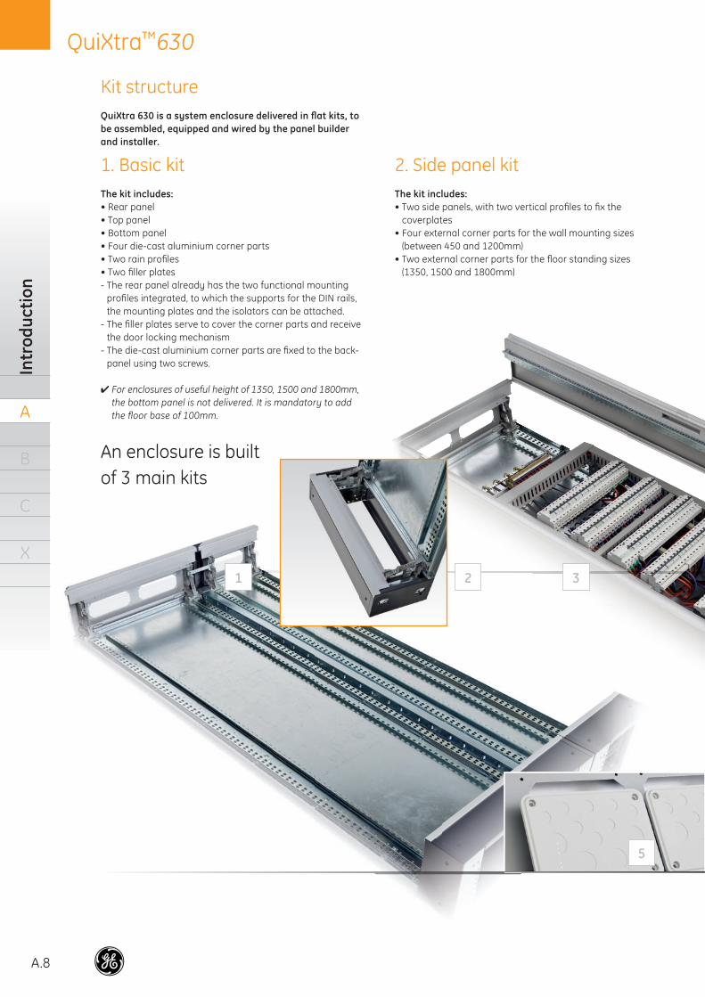
Kit structureQuiXtra 630 is a system enclosure delivered in fl at kits, to be assembled, equipped and wired by the panel builder and installer.
1. Basic kit The kit includes:• Rear panel• Top panel• Bottom panel• Four die-cast aluminium corner parts• Two rain profi les• Two fi ller plates- The rear panel already has the two functional mounting
profi les integrated, to which the supports for the DIN rails, the mounting plates and the isolators can be attached.
- The fi ller plates serve to cover the corner parts and receive the door locking mechanism
- The die-cast aluminium corner parts are fi xed to the back-panel using two screws.
✔ For enclosures of useful height of 1350, 1500 and 1800mm, the bottom panel is not delivered. It is mandatory to add the fl oor base of 100mm.
2. Side panel kitThe kit includes:• Two side panels, with two vertical profi les to fi x the
coverplates • Four external corner parts for the wall mounting sizes
(between 450 and 1200mm) • Two external corner parts for the fl oor standing sizes
(1350, 1500 and 1800mm)
An enclosure is builtof 3 main kits
1 2 3
5
A.9
QuiXtra™630Kit structure
A
B
C
X
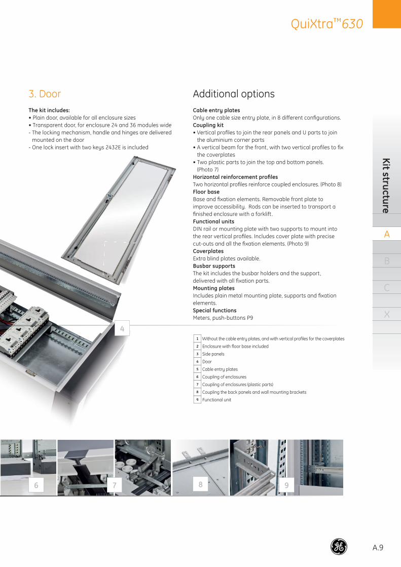
3. Door The kit includes:• Plain door, available for all enclosure sizes• Transparent door, for enclosure 24 and 36 modules wide- The locking mechanism, handle and hinges are delivered
mounted on the door- One lock insert with two keys 2432E is included
Additional optionsCable entry platesOnly one cable size entry plate, in 8 different confi gurations.Coupling kit• Vertical profi les to join the rear panels and U parts to join
the aluminium corner parts• A vertical beam for the front, with two vertical profi les to fi x
the coverplates• Two plastic parts to join the top and bottom panels.
(Photo 7)Horizontal reinforcement profi lesTwo horizontal profi les reinforce coupled enclosures. (Photo 8)Floor baseBase and fi xation elements. Removable front plate to improve accessibility. Rods can be inserted to transport a fi nished enclosure with a forklift .Functional unitsDIN rail or mounting plate with two supports to mount into the rear vertical profi les. Includes cover plate with precise cut-outs and all the fi xation elements. (Photo 9)CoverplatesExtra blind plates available.Busbar supportsThe kit includes the busbar holders and the support, delivered with all fi xation parts. Mounting platesIncludes plain metal mounting plate, supports and fi xation elements.Special functionsMeters, push-buttons P9
1 Without the cable entry plates, and with vertical profi les for the coverplates
2 Enclosure with fl oor base included
3 Side panels
4 Door
5 Cable entry plates
6 Coupling of enclosures
7 Coupling of enclosures (plastic parts)
8 Coupling the back panels and wall mounting brackets
9 Functional unit
4
6 87 9
A.10
QuiXtra™630In
trod
uctio
n
A
B
C
X
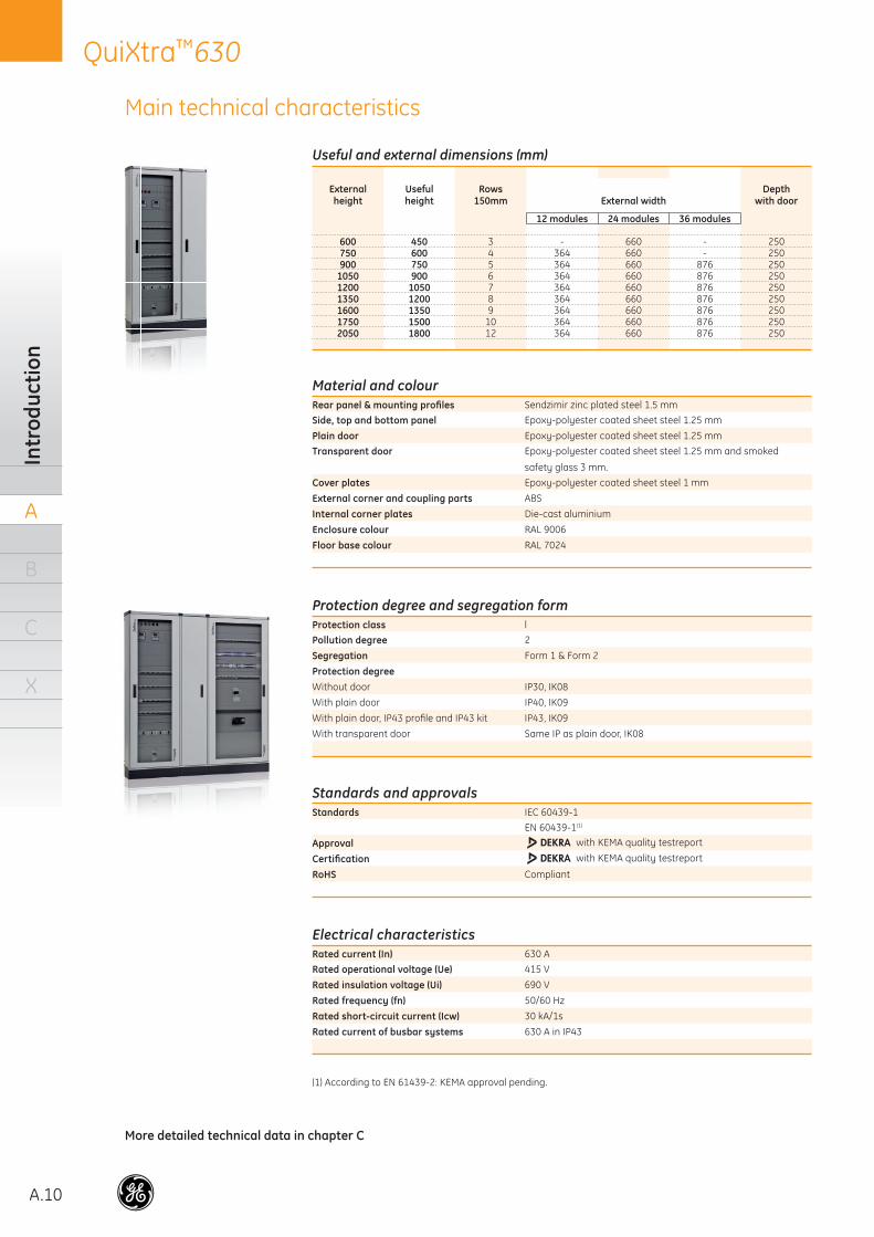
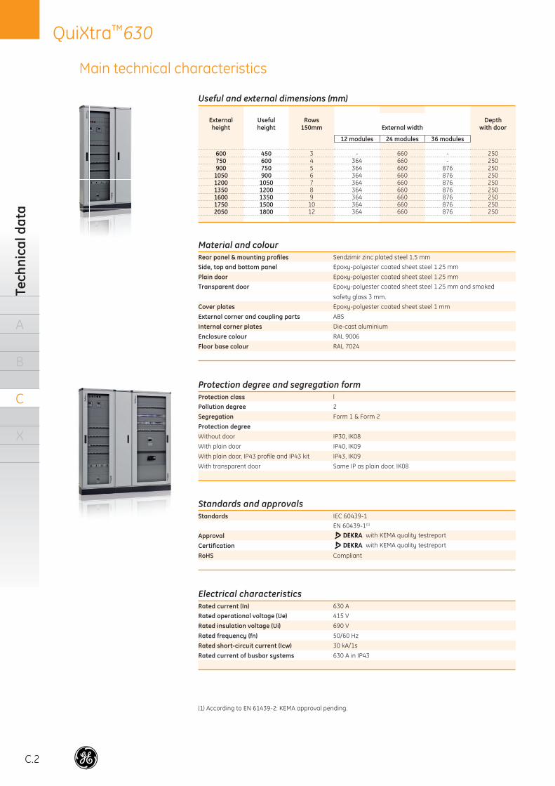
Material and colourRear panel & mounting profi les Sendzimir zinc plated steel 1.5 mm
Side, top and bottom panel Epoxy-polyester coated sheet steel 1.25 mm
Plain door Epoxy-polyester coated sheet steel 1.25 mm
Transparent door Epoxy-polyester coated sheet steel 1.25 mm and smoked
safety glass 3 mm.
Cover plates Epoxy-polyester coated sheet steel 1 mm
External corner and coupling parts ABS
Internal corner plates Die-cast aluminium
Enclosure colour RAL 9006
Floor base colour RAL 7024
Useful and external dimensions (mm)
Externalheight
Usefulheight
Rows150mm External width
Depthwith door
12 modules 24 modules 36 modules
600 450 3 - 660 - 250750 600 4 364 660 - 250900 750 5 364 660 876 250
1050 900 6 364 660 876 2501200 1050 7 364 660 876 2501350 1200 8 364 660 876 2501600 1350 9 364 660 876 2501750 1500 10 364 660 876 2502050 1800 12 364 660 876 250
Main technical characteristics
Protection degree and segregation formProtection class l
Pollution degree 2
Segregation Form 1 & Form 2
Protection degreeWithout door IP30, IK08
With plain door IP40, IK09
With plain door, IP43 profi le and IP43 kit IP43, IK09
With transparent door Same IP as plain door, IK08
Standards and approvalsStandards IEC 60439-1
EN 60439-1(1)
Approval with KEMA quality testreport
Certifi cation with KEMA quality testreport
RoHS Compliant
Electrical characteristicsRated current (In) 630 A
Rated operational voltage (Ue) 415 V
Rated insulation voltage (Ui) 690 V
Rated frequency (fn) 50/60 Hz
Rated short-circuit current (Icw) 30 kA/1s
Rated current of busbar systems 630 A in IP43
(1) According to EN 61439-2: KEMA approval pending.
More detailed technical data in chapter C
A.11
QuiXtra™630Range overview
A
B
C
X
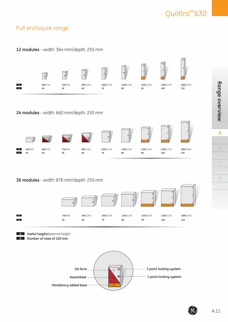
Full enclosure range
12 modules - width: 364 mm/depth: 250 mm
24 modules - width: 660 mm/depth: 250 mm
36 modules - width: 876 mm/depth: 250 mm
H Useful height/external heightR Number of rows of 150 mm
Kit form
Assembled
Mandatory added base
3 point locking system
1 point locking system
H 600/750 750/900 900/1050 1050/1200 1200/1350 1350/1600 1500/1750 1800/2050
R 4R 5R 6R 7R 8R 9R 10R 12R
H 450/600 600/750 750/900 900/1050 1050/1200 1200/1350 1350/1600 1500/1750 1800/2050
R 3R 4R 5R 6R 7R 8R 9R 10R 12R
H 750/900 900/1050 1050/1200 1200/1350 1350/1600 1500/1750 1800/2050
R 5R 6R 7R 8R 9R 10R 12R
B.2
QuiXtra™630O
rder
cod
es
A
B
C
X
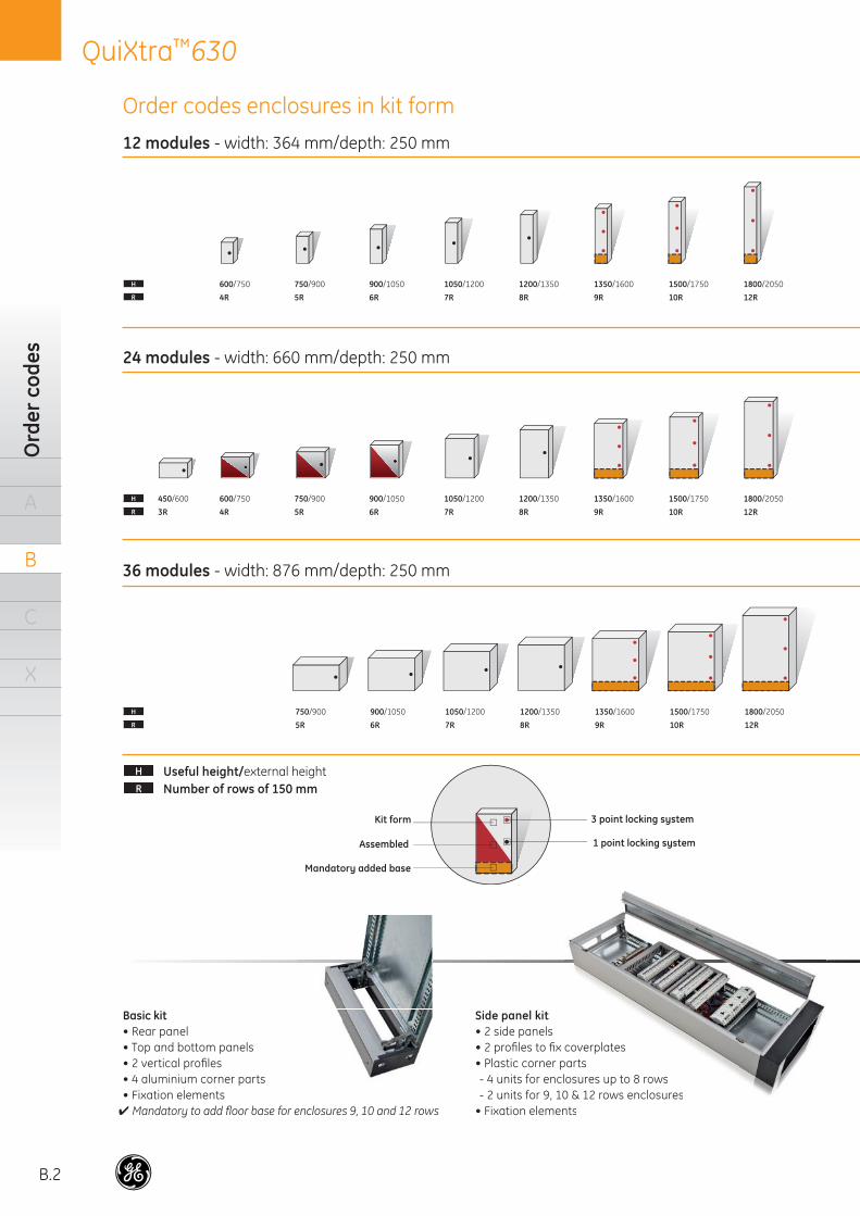
12 modules - width: 364 mm/depth: 250 mm
24 modules - width: 660 mm/depth: 250 mm
36 modules - width: 876 mm/depth: 250 mm
Order codes enclosures in kit form
H 600/750 750/900 900/1050 1050/1200 1200/1350 1350/1600 1500/1750 1800/2050
R 4R 5R 6R 7R 8R 9R 10R 12R
H 450/600 600/750 750/900 900/1050 1050/1200 1200/1350 1350/1600 1500/1750 1800/2050
R 3R 4R 5R 6R 7R 8R 9R 10R 12R
H 750/900 900/1050 1050/1200 1200/1350 1350/1600 1500/1750 1800/2050
R 5R 6R 7R 8R 9R 10R 12R
Side panel kit• 2 side panels• 2 profi les to fi x coverplates• Plastic corner parts- 4 units for enclosures up to 8 rows- 2 units for 9, 10 & 12 rows enclosures
• Fixation elements
coverplatesparts
osures up to 8 rows0 & 12 rows enclosuresnts
H Useful height/external heightR Number of rows of 150 mm
Kit form
Assembled
Mandatory added base
3 point locking system
1 point locking system
Basic kit• Rear panel• Top and bottom panels• 2 vertical profi les• 4 aluminium corner parts• Fixation elements✔ Mandatory to add fl oor base for enclosures 9, 10 and 12 rows
B.3
QuiXtra™630Basic kits
A
B
C
X
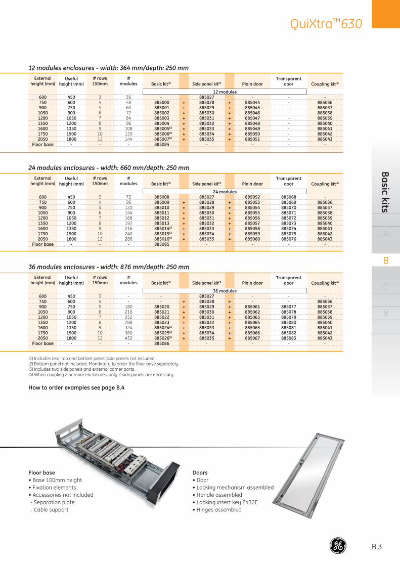
12 modules enclosures - width: 364 mm/depth: 250 mmExternal
height (mm)Useful
height (mm)# rows150mm
#modules
TransparentdoorBasic kit(1) Side panel kit(3) Plain door Coupling kit(4)
12 modules600 450 3 36 - 885027 - - -750 600 4 48 885000 + 885028 + 885044 - 885036900 750 5 60 885001 + 885029 + 885045 - 885037
1050 900 6 72 885002 + 885030 + 885046 - 8850381200 1050 7 84 885003 + 885031 + 885047 - 8850391350 1200 8 96 885004 + 885032 + 885048 - 8850401600 1350 9 108 885005(2) + 885033 + 885049 - 8850411750 1500 10 120 885006(2) + 885034 + 885050 - 8850422050 1800 12 144 885007(2) + 885035 + 885051 - 885043
Floor base - - - 885084 - - - -
24 modules enclosures - width: 660 mm/depth: 250 mmExternal
height (mm)Useful
height (mm)# rows150mm
#modules
TransparentdoorBasic kit(1) Side panel kit(3) Plain door Coupling kit(4)
24 modules600 450 3 72 885008 885027 885052 885068 -750 600 4 96 885009 + 885028 + 885053 885069 885036900 750 5 120 885010 + 885029 + 885054 885070 885037
1050 900 6 144 885011 + 885030 + 885055 885071 8850381200 1050 7 168 885012 + 885031 + 885056 885072 8850391350 1200 8 192 885013 + 885032 + 885057 885073 8850401600 1350 9 216 885014(2) + 885033 + 885058 885074 8850411750 1500 10 240 885015(2) + 885034 + 885059 885075 8850422050 1800 12 288 885016(2) + 885035 + 885060 885076 885043
Floor base - - - 885085 - - - -
36 modules enclosures - width: 876 mm/depth: 250 mmExternal
height (mm)Useful
height (mm)# rows150mm
#modules
TransparentdoorBasic kit(1) Side panel kit(3) Plain door Coupling kit(4)
36 modules600 450 3 - - 885027 - - -750 600 4 - - + 885028 + - - 885036900 750 5 180 885020 + 885029 + 885061 885077 885037
1050 900 6 216 885021 + 885030 + 885062 885078 8850381200 1050 7 252 885022 + 885031 + 885063 885079 8850391350 1200 8 288 885023 + 885032 + 885064 885080 8850401600 1350 9 324 885024(2) + 885033 + 885065 885081 8850411750 1500 10 360 885025(2) + 885034 + 885066 885082 8850422050 1800 12 432 885026(2) + 885035 + 885067 885083 885043
Floor base - - - 885086 - - - -
(1) Includes rear, top and bottom panel (side panels not included).(2) Bottom panel not included. Mandatory to order the fl oor base separately.(3) Includes two side panels and external corner parts.(4) When coupling 2 or more enclosures, only 2 side panels are necessary.
How to order examples see page B.4
Floor base• Base 100mm height• Fixation elements• Accessories not included- Separation plate- Cable support
e0mm heightelementsries not includedion plate
upport
Doors• Door• Locking mechanism assembled• Handle assembled• Locking insert key 2432E• Hinges assembled
B.4
QuiXtra™630O
rder
cod
es
A
B
C
X
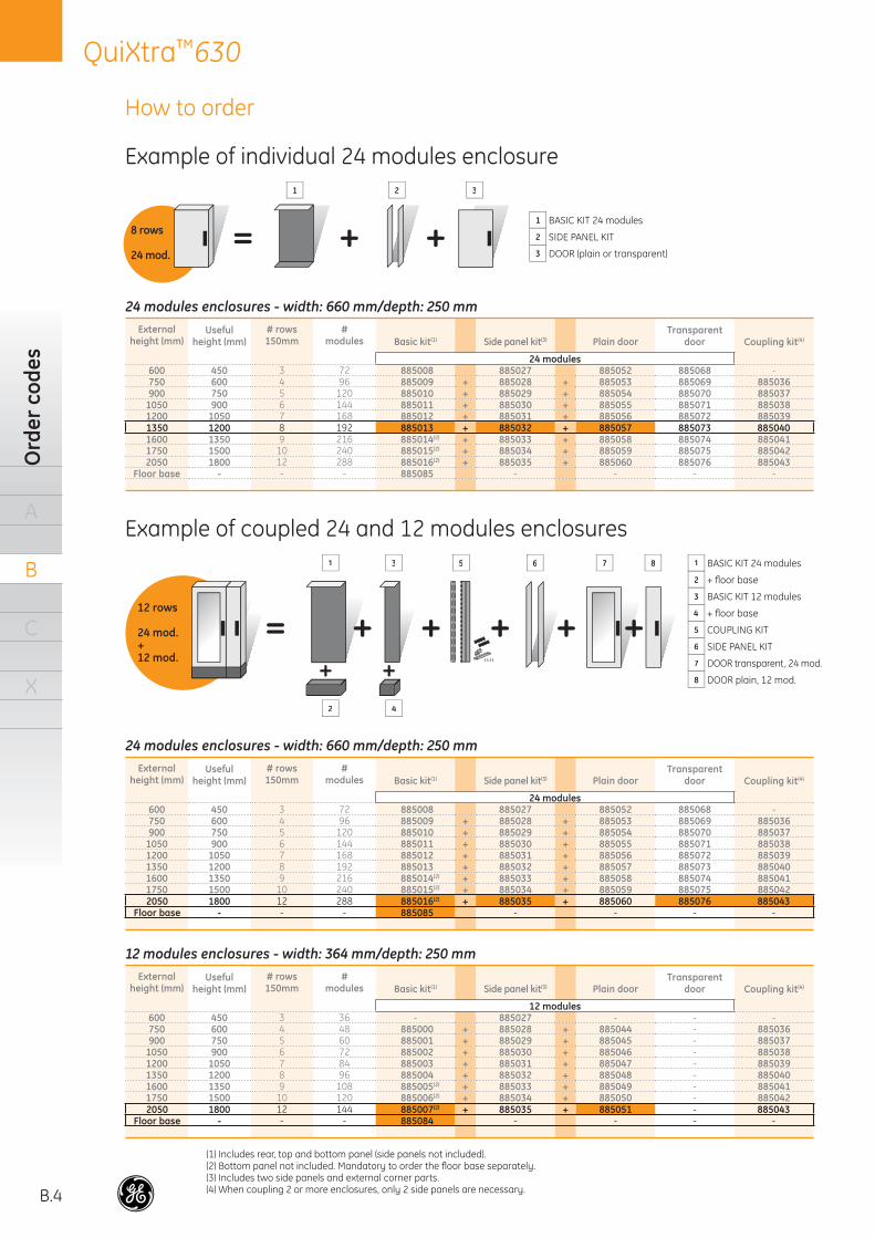
How to order
Example of individual 24 modules enclosure
Example of coupled 24 and 12 modules enclosures
= + +
=+ +
++ + ++
1 BASIC KIT 24 modules
2 SIDE PANEL KIT
3 DOOR (plain or transparent)
1 BASIC KIT 24 modules
2 + fl oor base
3 BASIC KIT 12 modules
4 + fl oor base
5 COUPLING KIT
6 SIDE PANEL KIT
7 DOOR transparent, 24 mod.
8 DOOR plain, 12 mod.
1 2 3
1
2
63
4
75 8
24 modules enclosures - width: 660 mm/depth: 250 mmExternal
height (mm)Useful
height (mm)# rows 150mm
#modules
TransparentdoorBasic kit(1) Side panel kit(3) Plain door Coupling kit(4)
24 modules600 450 3 72 885008 885027 885052 885068 -750 600 4 96 885009 + 885028 + 885053 885069 885036900 750 5 120 885010 + 885029 + 885054 885070 885037
1050 900 6 144 885011 + 885030 + 885055 885071 8850381200 1050 7 168 885012 + 885031 + 885056 885072 8850391350 1200 8 192 885013 + 885032 + 885057 885073 8850401600 1350 9 216 885014(2) + 885033 + 885058 885074 8850411750 1500 10 240 885015(2) + 885034 + 885059 885075 8850422050 1800 12 288 885016(2) + 885035 + 885060 885076 885043
Floor base - - - 885085 - - - -
12 modules enclosures - width: 364 mm/depth: 250 mmExternal
height (mm)Useful
height (mm)# rows 150mm
#modules
TransparentdoorBasic kit(1) Side panel kit(3) Plain door Coupling kit(4)
12 modules600 450 3 36 - 885027 - - -750 600 4 48 885000 + 885028 + 885044 - 885036900 750 5 60 885001 + 885029 + 885045 - 885037
1050 900 6 72 885002 + 885030 + 885046 - 8850381200 1050 7 84 885003 + 885031 + 885047 - 8850391350 1200 8 96 885004 + 885032 + 885048 - 8850401600 1350 9 108 885005(2) + 885033 + 885049 - 8850411750 1500 10 120 885006(2) + 885034 + 885050 - 8850422050 1800 12 144 885007(2) + 885035 + 885051 - 885043
Floor base - - - 885084 - - - -
(1) Includes rear, top and bottom panel (side panels not included).(2) Bottom panel not included. Mandatory to order the fl oor base separately.(3) Includes two side panels and external corner parts.(4) When coupling 2 or more enclosures, only 2 side panels are necessary.
8 rows
24 mod.
12 rows
24 mod.+12 mod.
B.5
QuiXtra™630Assem
bled enclosures
A
B
C
X
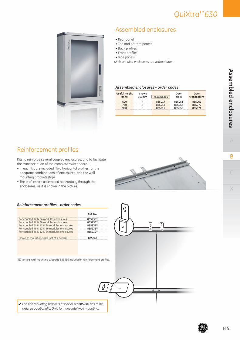
Assembled enclosures• Rear panel• Top and bottom panels• Back profi les• Front profi les• Side panels✔ Assembled enclosures are without door
Reinforcement profilesKits to reinforce several coupled enclosures, and to facilitate the transportation of the complete switchboard. • In each kit are included: Two horizontal profi les for the
adequate combinations of enclosures, and the wall mounting brackets (top).
• The profi les are assembled horizontally through the enclosures, as it is shown in the picture.
Reinforcement profi les - order codes
Ref. No.
For coupled 12 & 24 modules enclosures 885235(1)
For coupled 12 & 36 modules enclosures 885236(1)
For coupled 24 & 12 & 24 modules enclosures 885237(1)
For coupled 36 & 12 & 36 modules enclosures 885238(1)
For coupled 36 & 12 & 24 modules enclosures 885239(1)
Hooks to mount on sides (set of 4 hooks) 885240
✔ For side mounting brackets a special set 885240 has to be ordered additionally. Only for horizontal wall mounting.
(1) Vertical wall mounting supports 885256 included in reinforcement profi les.
Assembled enclosures - order codesUseful height
(mm)# rows150mm 24 modules
Doorplain
Doortransparent
600 4 885017 885053 885069750 5 885018 885054 885070900 6 885019 885055 885071
B.6
QuiXtra™630O
rder
cod
es
A
B
C
X
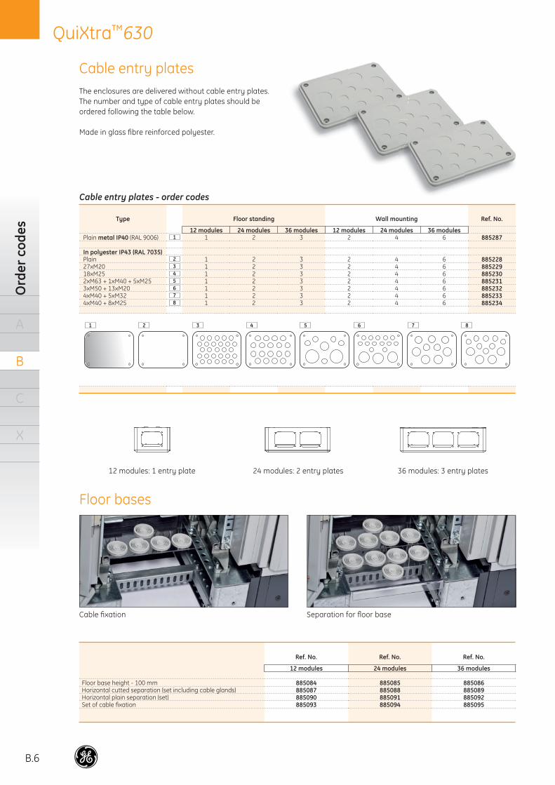
Cable entry platesThe enclosures are delivered without cable entry plates.The number and type of cable entry plates should be ordered following the table below.
Made in glass fi bre reinforced polyester.
Cable entry plates - order codes
Type Floor standing Wall mounting Ref. No.
12 modules 24 modules 36 modules 12 modules 24 modules 36 modulesPlain metal IP40 (RAL 9006) 1 1 2 3 2 4 6 885287
In polyester IP43 (RAL 7035)Plain 2 1 2 3 2 4 6 88522827xM20 3 1 2 3 2 4 6 88522918xM25 4 1 2 3 2 4 6 8852302xM63 + 1xM40 + 5xM25 5 1 2 3 2 4 6 8852313xM50 + 13xM20 6 1 2 3 2 4 6 8852324xM40 + 5xM32 7 1 2 3 2 4 6 8852334xM40 + 8xM25 8 1 2 3 2 4 6 885234
21 3 4 5 6 7 8
24 modules: 2 entry plates 36 modules: 3 entry plates12 modules: 1 entry plate
Floor bases
Ref. No. Ref. No. Ref. No.
12 modules 24 modules 36 modules
Floor base height - 100 mm 885084 885085 885086Horizontal cutted separation (set including cable glands) 885087 885088 885089Horizontal plain separation (set) 885090 885091 885092Set of cable fi xation 885093 885094 885095
Cable fi xation Separation for fl oor base
B.7
QuiXtra™630Functional units
A
B
C
X
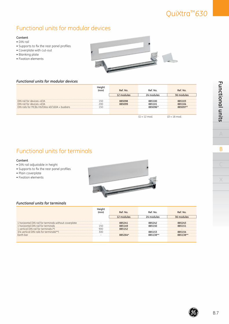
Functional units for modular devices
Functional units for terminals
Functional units for modular devicesHeight(mm) Ref. No. Ref. No. Ref. No.
12 modules 24 modules 36 modules
DIN rail for devices <63A 150 885098 885100 885103DIN rail for devices >63A 200 885099 885101 885104DIN rails for MCBs Hti/Dilos 40/160A + busbars 150 - 885096(1) 885097(2)
(1) + 12 mod. (2) + 18 mod.
Content• DIN rail adjustable in height• Supports to fi x the rear panel profi les• Plain coverplate• Fixation elements
Content• DIN rail• Supports to fi x the rear panel profi les• Coverplate with cut-out• Blanking plate• Fixation elements
Functional units for terminalsHeight(mm) Ref. No. Ref. No. Ref. No.
12 modules 24 modules 36 modules
1 horizontal DIN rail for terminals without coverplate - 885241 885242 8852431 horizontal DIN rail for terminals 150 885149 885150 8851511 vertical DIN rail for terminals (*) 900 885152 - -3/4 vertical DIN rails for terminals(**) 300 - 885153 885154Earth bar - 885264* 885138** 885138**
B.8
QuiXtra™630O
rder
cod
es
A
B
C
X
CLICK
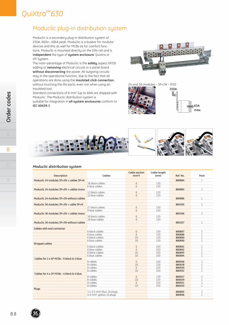
Moduclic is a secondary plug-in distribution system of 250A, 660V~ 60kA peak. Moduclic is a busbar for modular devices and this as well for MCBs as for comfort func-tions. Moduclic is mounted directly on the DIN-rail and is independent the type of system enclosure: Quixtra or VP-System.The main advantage of Moduclic is the safety aspect (IP20): adding or removing electrical circuits in a panel board without disconnecting the power. All outgoing circuits stay in the operational function, due to the fact that all operations are done using the insulated click connection, without touching the life parts, even not when using an insulated tool.Standard connections of 6 mm2 (up to 40A) are shipped with Moduclic. The Moduclic distribution system is suitable for integration in all system enclosures conform to IEC 60439-1
24 and 36 modules - 3P+2N - IP20
250 A
63 Amax.63Amax.
250A
Moduclic distribution system
Description CablesCable section
(mm²)Cable length
(mm) Ref. No. Pack
Moduclic 24 modules 3P+2N + cables 3P+N 880884 118 black cables 6 1206 blue cables 6 120
Moduclic 24 modules 3P+2N + cables mono 880885 112 black cables 6 12012 blue cables 6 120
Moduclic 24 modules 3P+2N without cables - - 880886 1
Moduclic 36 modules 3P+2N + cable 3P+N 885265 127 black cables 6 1209 blue cables 6 120
Moduclic 36 modules 3P+2N + cables mono 885266 118 black cables 6 12018 blue cables 6 120
Moduclic 36 modules 3P+2N without cables - - 885267 1
Cables with end connector6 black cables 6 120 880887 16 blue cables 6 120 880888 16 black cables 10 120 880889 16 blue cables 10 120 880890 1
Stripped cables6 black cables 6 320 880891 16 blue cables 6 320 880892 16 black cables 10 320 880893 16 blue cables 10 320 880894 1
Cables for 2 x 4P MCBs - 6 black & 2 blue8 cables 6 120 880926 18 cables 10 120 880928 18 cables 6 320 880930 18 cables 10 320 880932 1
Cables for 4 x 2P MCBs - 4 black & 4 blue8 cables 6 120 880927 18 cables 10 120 880929 18 cables 6 320 880931 18 cables 10 320 880933 1
Plugs1.5-2.5 mm² blue, 10 plugs 880895 14-6 mm² yellow, 10 plugs 880896 1
Moduclic plug-in distribution system
B.9
QuiXtra™630M
oduclic plug-in distribution system
A
B
C
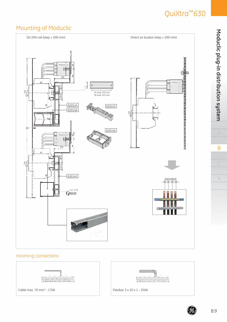
X60 60 60
Cable max. 70 mm2 - 170A Flexibar 3 x 20 x 1 - 250A
On DIN-rail (step = 200 mm) Direct on busbar (step = 200 mm)
Mounting of Moduclic
Incoming connections
200
200
828146
828146828145828145
828145
24 mod. 359 mm36 mod. 553 mm
4,2 x 9,5
MODUCLIC
MODUCLIC
65
65
MODUCLIC
200
B.10
QuiXtra™630O
rder
cod
es
A
B
C
X
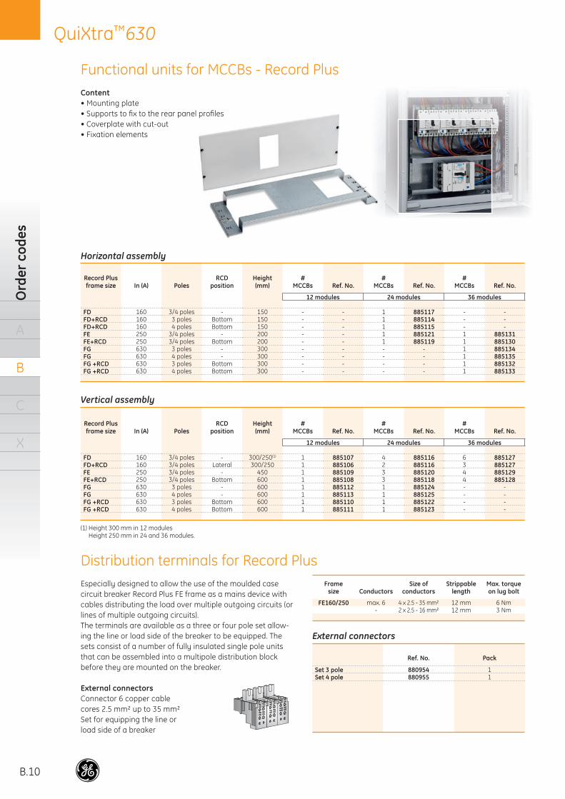
Content• Mounting plate• Supports to fi x to the rear panel profi les• Coverplate with cut-out• Fixation elements
Especially designed to allow the use of the moulded case circuit breaker Record Plus FE frame as a mains device with cables distributing the load over multiple outgoing circuits (or lines of multiple outgoing circuits).The terminals are available as a three or four pole set allow-ing the line or load side of the breaker to be equipped. The sets consist of a number of fully insulated single pole units that can be assembled into a multipole distribution block before they are mounted on the breaker.
External connectorsConnector 6 copper cable cores 2.5 mm² up to 35 mm²Set for equipping the line or load side of a breaker
Functional units for MCCBs - Record Plus
Horizontal assembly
Record Plus frame size In (A) Poles
RCD position
Height(mm)
#MCCBs Ref. No.
#MCCBs Ref. No.
#MCCBs Ref. No.
12 modules 24 modules 36 modules
FD 160 3/4 poles - 150 - - 1 885117 - -FD+RCD 160 3 poles Bottom 150 - - 1 885114 - -FD+RCD 160 4 poles Bottom 150 - - 1 885115 - -FE 250 3/4 poles - 200 - - 1 885121 1 885131FE+RCD 250 3/4 poles Bottom 200 - - 1 885119 1 885130FG 630 3 poles - 300 - - - - 1 885134FG 630 4 poles - 300 - - - - 1 885135FG +RCD 630 3 poles Bottom 300 - - - - 1 885132FG +RCD 630 4 poles Bottom 300 - - - - 1 885133
Vertical assembly
Record Plus frame size In (A) Poles
RCD position
Height(mm)
#MCCBs Ref. No.
#MCCBs Ref. No.
#MCCBs Ref. No.
12 modules 24 modules 36 modules
FD 160 3/4 poles - 300/250(1) 1 885107 4 885116 6 885127FD+RCD 160 3/4 poles Lateral 300/250 1 885106 2 885116 3 885127FE 250 3/4 poles - 450 1 885109 3 885120 4 885129FE+RCD 250 3/4 poles Bottom 600 1 885108 3 885118 4 885128FG 630 3 poles - 600 1 885112 1 885124 - -FG 630 4 poles - 600 1 885113 1 885125 - -FG +RCD 630 3 poles Bottom 600 1 885110 1 885122 - -FG +RCD 630 4 poles Bottom 600 1 885111 1 885123 - -
(1) Height 300 mm in 12 modulesHeight 250 mm in 24 and 36 modules.
External connectors
Ref. No. Pack
Set 3 pole 880954 1Set 4 pole 880955 1
Framesize Conductors
Size of conductors
Strippablelength
Max. torqueon lug bolt
FE160/250 max. 6 4 x 2.5 - 35 mm² 12 mm 6 Nm- 2 x 2.5 - 16 mm² 12 mm 3 Nm
Distribution terminals for Record Plus
B.11
QuiXtra™630O
rder codes
A
B
C
X
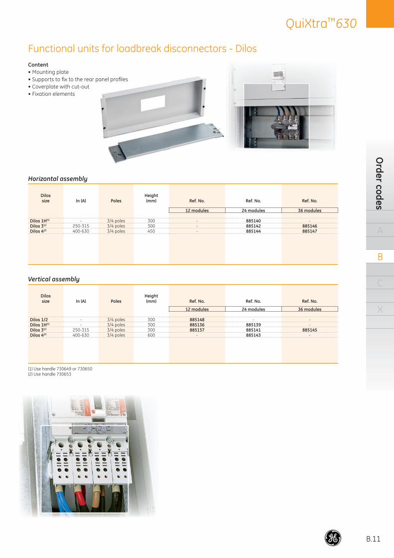
Content• Mounting plate• Supports to fi x to the rear panel profi les• Coverplate with cut-out• Fixation elements
Functional units for loadbreak disconnectors - Dilos
Horizontal assembly
Dilossize In (A) Poles
Height(mm) Ref. No. Ref. No. Ref. No.
12 modules 24 modules 36 modules
Dilos 1H(1) - 3/4 poles 300 - 885140 -Dilos 3(1) 250-315 3/4 poles 300 - 885142 885146Dilos 4(2) 400-630 3/4 poles 450 - 885144 885147
Vertical assembly
Dilossize In (A) Poles
Height(mm) Ref. No. Ref. No. Ref. No.
12 modules 24 modules 36 modules
Dilos 1/2 - 3/4 poles 300 885148 - -Dilos 1H(1) - 3/4 poles 300 885136 885139 -Dilos 3(1) 250-315 3/4 poles 300 885137 885141 885145Dilos 4(2) 400-630 3/4 poles 600 - 885143 -
(1) Use handle 730649 or 730650(2) Use handle 730653
B.12
QuiXtra™630O
rder
cod
es
A
B
C
X
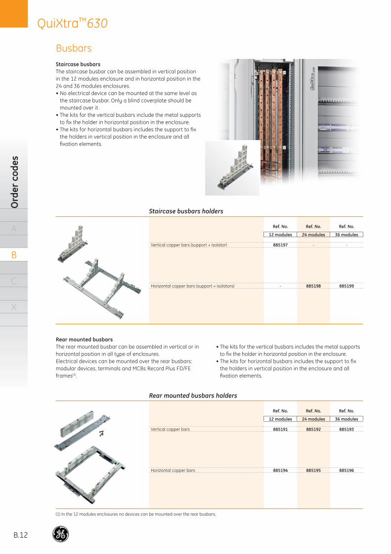
Staircase busbarsThe staircase busbar can be assembled in vertical position in the 12 modules enclosure and in horizontal position in the 24 and 36 modules enclosures.• No electrical device can be mounted at the same level as
the staircase busbar. Only a blind coverplate should be mounted over it .
• The kits for the vertical busbars include the metal supports to fi x the holder in horizontal position in the enclosure.
• The kits for horizontal busbars includes the support to fi x the holders in vertical position in the enclosure and all fi xation elements.
Busbars
Staircase busbars holders
Ref. No. Ref. No. Ref. No.
12 modules 24 modules 36 modules
Vertical copper bars (support + isolator) 885197 - -
Horizontal copper bars (support + isolators) - 885198 885199
Rear mounted busbars holders
Ref. No. Ref. No. Ref. No.
12 modules 24 modules 36 modules
Vertical copper bars 885191 885192 885193
Horizontal copper bars 885194 885195 885196
(1) In the 12 modules enclosures no devices can be mounted over the rear busbars.
Rear mounted busbarsThe rear mounted busbar can be assembled in vertical or in horizontal position in all type of enclosures.Electrical devices can be mounted over the rear busbars:modular devices, terminals and MCBs Record Plus FD/FE frames(1).
• The kits for the vertical busbars includes the metal supports to fi x the holder in horizontal position in the enclosure.
• The kits for horizontal busbars includes the support to fi x the holders in vertical position in the enclosure and all fi xation elements.
B.13
QuiXtra™630Busbar system
A
B
C
X
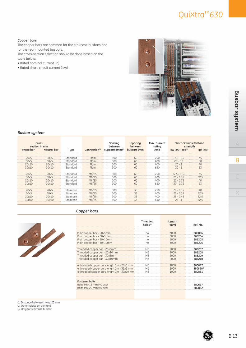
Copper barsThe copper bars are common for the staircase busbars and for the rear mounted busbars.The cross-section selection should be done based on the table below:• Rated nominal current (In)• Rated short-circuit current (Icw)
Busbar system
Crosssection in mm
Phase bar Neutral bar Type Connection(1)
Spacing between
supports (mm)(2)
Spacing between
busbars (mm)
Max. CurrentratingAmp
Short-circuit withstandstrength
Icw (kA) - sec(2) Ipk (kA)
20x5 20x5 Standard Plain 300 60 250 17.5 - 0.7 3530x5 30x5 Standard Plain 300 60 400 25 - 0.8 50
20x10 20x10 Standard Plain 300 60 400 20 - 1 4030x10 30x10 Standard Plain 300 60 630 30 - 1 63
20x5 20x5 Standard M6/25 300 60 250 17.5 - 0.35 3530x5 30x5 Standard M6/25 300 60 400 25 - 0.35 52.5
20x10 20x10 Standard M6/25 300 60 400 20 - 0.75 4030x10 30x10 Standard M8/25 300 60 630 30 - 0.75 63
20x5 20x5 Staircase M6/25 300 35 250 20 - 0.35 4030x5 30x5 Staircase M6/25 300 35 400 25 - 0.35 52.5
20x10 20x10 Staircase M6/25 300 35 400 25 - 0.45 52.530x10 30x10 Staircase M8/25 300 35 630 25 - 1 52.5
Copper bars
Threadedholes(1)
Length(mm) Ref. No.
Plain copper bar - 20x5mm no 3000 885036Plain copper bar - 30x5mm no 3000 885204Plain copper bar - 20x10mm no 3000 885205Plain copper bar - 30x10mm no 3000 885206
Threaded copper bar - 20x5mm M6 2000 885207Threaded copper bar - 20x10mm M6 2000 885208Threaded copper bar - 30x5mm M6 2000 885209Threaded copper bar - 30x10mm M8 2000 885210
4 threaded copper bars length 1m - 20x5 mm M6 1000 8808474 threaded copper bars lenght 1m - 32x5 mm M6 1000 880850(3)
4 threaded copper bars lenght 1m - 30x10 mm M8 1000 880851
Fastener boltsBolts M6x16 mm (40 pcs) 880617Bolts M8x20 mm (40 pcs) 880852
(1) Distance between holes: 25 mm(2) Other values on demand(3) Only for staircase busbar
B.14
QuiXtra™630O
rder
cod
es
A
B
C
X
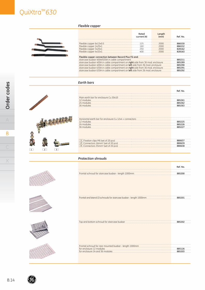
Flexible copper
Ratedcurrent (A)
Length(mm) Ref. No.
Flexible copper 6x13x0.5 125 2000 886530Flexible copper 2x20x1 160 2000 886532Flexible copper 3x20x1 250 2000 828162Flexible copper 4x32x1 400 2000 828163
Flexible copper connection between Record Plus FG and:staircase busbar 400A/630A in cable compartment 885211staircase busbar 400A in cable compartment on right side from 36 mod. enclosure 885289staircase busbar 400A in cable compartment on left side from 36 mod. enclosure 885290staircase busbar 630A in cable compartment on right side from 36 mod. enclosure 885291staircase busbar 630A in cable compartment on left side from 36 mod. enclosure 885292
Earth bars
Ref. No.
Main earth bar for enclosure Cu 30x1012 modules 88526124 modules 88526236 modules 885263
Horizontal earth bar for enclosure Cu 12x4 + connectors12 modules 88522524 modules 88522636 modules 885227
1 Fixation clips M6 (set of 20 pcs) 8806372 Connectors 16mm² (set of 20 pcs) 8806393 Connectors 35mm² (set of 20 pcs) 880638
1 2 3
Protection shrouds
Ref. No.
Frontal schroud for staircase busbar - length 1000mm 885200
Frontal and lateral (2) schrouds for staircase busbar - length 1000mm 885201
Top and bottom schroud for staircase busbar 885202
Frontal schroud for rear mounted busbar - length 1000mm for enclosure 12 modules 885126for enclosure 24 and 36 modules 885203
B.15
QuiXtra™630Internal separation
A
B
C
X
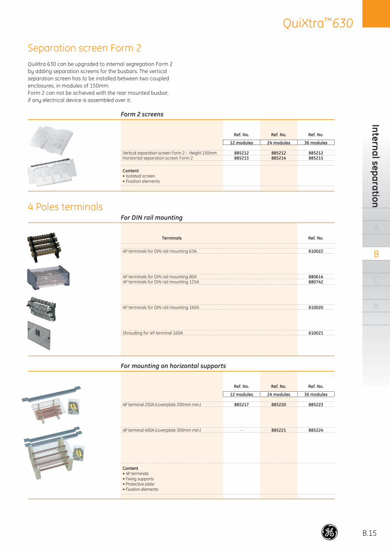
Form 2 screens
Ref. No. Ref. No. Ref. No.
12 modules 24 modules 36 modules
Vertical separation screen Form 2 - Height 150mm 885212 885212 885212Horizontal separation screen Form 2 885213 885214 885215
Content• Isolated screen• Fixation elements
For mounting on horizontal supports
Ref. No. Ref. No. Ref. No.
12 modules 24 modules 36 modules
4P terminal 250A (coverplate 200mm min.) 885217 885220 885223
4P terminal 400A (coverplate 300mm min.) - 885221 885224
Content• 4P terminals• Fixing supports• Protective plate• Fixation elements
For DIN rail mounting
Terminals Ref. No.
4P terminals for DIN rail mounting 63A 610022
4P terminals for DIN rail mounting 80A 8806144P terminals for DIN rail mounting 125A 880742
4P terminals for DIN rail mounting 160A 610020
Shrouding for 4P terminal 160A 610021
QuiXtra 630 can be upgraded to internal segregation Form 2by adding separation screens for the busbars. The vertical separation screen has to be installed between two coupled enclosures, in modules of 150mm.Form 2 can not be achieved with the rear mounted busbar, if any electrical device is assembled over it .
4 Poles terminals
Separation screen Form 2
B.16
QuiXtra™630O
rder
cod
es
A
B
C
X
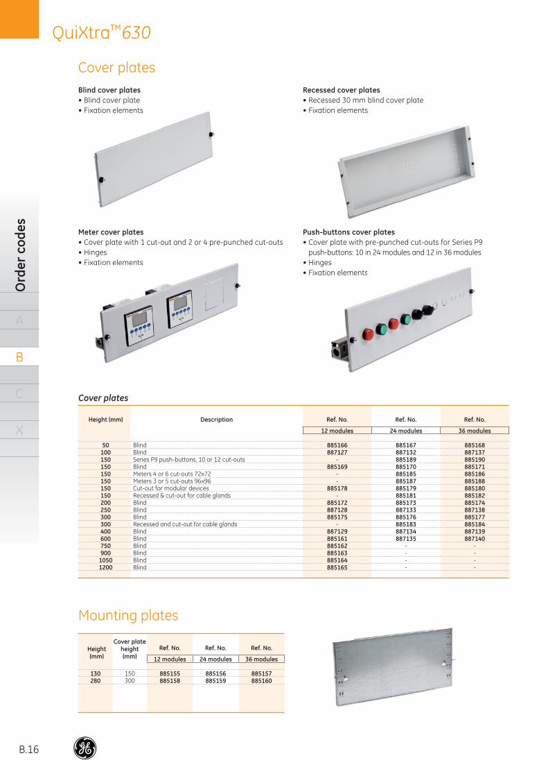
Blind cover plates• Blind cover plate• Fixation elements
Recessed cover plates• Recessed 30 mm blind cover plate• Fixation elements
Meter cover plates• Cover plate with 1 cut-out and 2 or 4 pre-punched cut-outs• Hinges• Fixation elements
Push-buttons cover plates• Cover plate with pre-punched cut-outs for Series P9
push-buttons: 10 in 24 modules and 12 in 36 modules• Hinges• Fixation elements
Height(mm)
Cover plateheight(mm)
Ref. No. Ref. No. Ref. No.
12 modules 24 modules 36 modules
130 150 885155 885156 885157280 300 885158 885159 885160
Cover plates
• Fixation elements
• Fixation elements son elements
Cover plates
Height (mm) Description Ref. No. Ref. No. Ref. No.
12 modules 24 modules 36 modules
50 Blind 885166 885167 885168100 Blind 887127 887132 887137150 Series P9 push-buttons, 10 or 12 cut-outs - 885189 885190150 Blind 885169 885170 885171150 Meters 4 or 6 cut-outs 72x72 - 885185 885186150 Meters 3 or 5 cut-outs 96x96 - 885187 885188150 Cut-out for modular devices 885178 885179 885180150 Recessed & cut-out for cable glands - 885181 885182200 Blind 885172 885173 885174250 Blind 887128 887133 887138300 Blind 885175 885176 885177300 Recessed and cut-out for cable glands - 885183 885184400 Blind 887129 887134 887139600 Blind 885161 887135 887140750 Blind 885162 - -900 Blind 885163 - -
1050 Blind 885164 - -1200 Blind 885165 - -
Mounting plates
B.17
QuiXtra™630Accessories
A
B
C
X
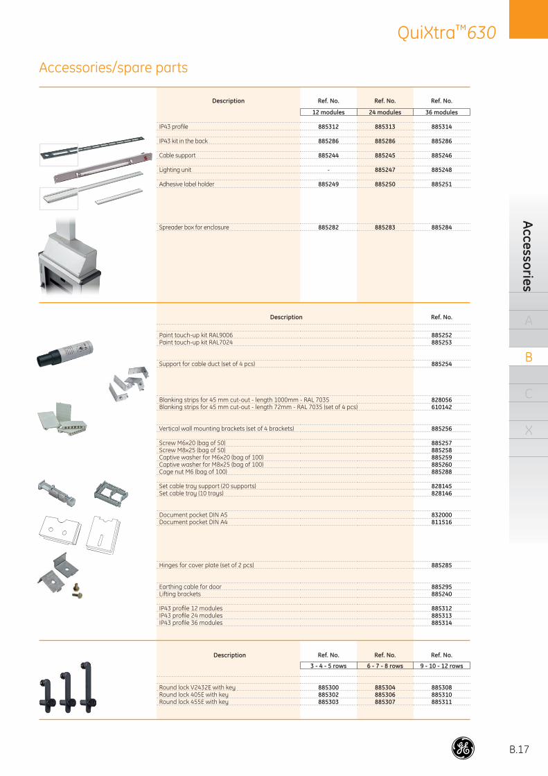
Description Ref. No. Ref. No. Ref. No.
12 modules 24 modules 36 modules
IP43 profi le 885312 885313 885314
IP43 kit in the back 885286 885286 885286
Cable support 885244 885245 885246
Lighting unit - 885247 885248
Adhesive label holder 885249 885250 885251
Spreader box for enclosure 885282 885283 885284
Description Ref. No.
Paint touch-up kit RAL9006 885252Paint touch-up kit RAL7024 885253
Support for cable duct (set of 4 pcs) 885254
Blanking strips for 45 mm cut-out - length 1000mm - RAL 7035 828056Blanking strips for 45 mm cut-out - length 72mm - RAL 7035 (set of 4 pcs) 610142
Vertical wall mounting brackets (set of 4 brackets) 885256
Screw M6x20 (bag of 50) 885257Screw M8x25 (bag of 50) 885258Captive washer for M6x20 (bag of 100) 885259Captive washer for M8x25 (bag of 100) 885260Cage nut M6 (bag of 100) 885288
Set cable tray support (20 supports) 828145Set cable tray (10 trays) 828146
Document pocket DIN A5 832000Document pocket DIN A4 811516
Hinges for cover plate (set of 2 pcs) 885285
Earthing cable for door 885295Lifting brackets 885240
IP43 profi le 12 modules 885312IP43 profi le 24 modules 885313IP43 profi le 36 modules 885314
Description Ref. No. Ref. No. Ref. No.
3 - 4 - 5 rows 6 - 7 - 8 rows 9 - 10 - 12 rows
Round lock V2432E with key 885300 885304 885308Round lock 405E with key 885302 885306 885310Round lock 455E with key 885303 885307 885311
Accessories/spare parts

B.18
QuiXtra™630O
rder
cod
es
A
B
C
X
Notes
. . . . . . . . . . . . . . . . . . . . . . . . . . . . . . . . . . . . . . . . . .
. . . . . . . . . . . . . . . . . . . . . . . . . . . . . . . . . . . . . . . . . .
. . . . . . . . . . . . . . . . . . . . . . . . . . . . . . . . . . . . . . . . . .
. . . . . . . . . . . . . . . . . . . . . . . . . . . . . . . . . . . . . . . . . .
. . . . . . . . . . . . . . . . . . . . . . . . . . . . . . . . . . . . . . . . . .
. . . . . . . . . . . . . . . . . . . . . . . . . . . . . . . . . . . . . . . . . .
. . . . . . . . . . . . . . . . . . . . . . . . . . . . . . . . . . . . . . . . . .
. . . . . . . . . . . . . . . . . . . . . . . . . . . . . . . . . . . . . . . . . .
. . . . . . . . . . . . . . . . . . . . . . . . . . . . . . . . . . . . . . . . . .
. . . . . . . . . . . . . . . . . . . . . . . . . . . . . . . . . . . . . . . . . .
. . . . . . . . . . . . . . . . . . . . . . . . . . . . . . . . . . . . . . . . . .
. . . . . . . . . . . . . . . . . . . . . . . . . . . . . . . . . . . . . . . . . .
. . . . . . . . . . . . . . . . . . . . . . . . . . . . . . . . . . . . . . . . . .
. . . . . . . . . . . . . . . . . . . . . . . . . . . . . . . . . . . . . . . . . .
. . . . . . . . . . . . . . . . . . . . . . . . . . . . . . . . . . . . . . . . . .
. . . . . . . . . . . . . . . . . . . . . . . . . . . . . . . . . . . . . . . . . .
. . . . . . . . . . . . . . . . . . . . . . . . . . . . . . . . . . . . . . . . . .
. . . . . . . . . . . . . . . . . . . . . . . . . . . . . . . . . . . . . . . . . .
. . . . . . . . . . . . . . . . . . . . . . . . . . . . . . . . . . . . . . . . . .
. . . . . . . . . . . . . . . . . . . . . . . . . . . . . . . . . . . . . . . . . .
. . . . . . . . . . . . . . . . . . . . . . . . . . . . . . . . . . . . . . . . . .
. . . . . . . . . . . . . . . . . . . . . . . . . . . . . . . . . . . . . . . . . .
. . . . . . . . . . . . . . . . . . . . . . . . . . . . . . . . . . . . . . . . . .
. . . . . . . . . . . . . . . . . . . . . . . . . . . . . . . . . . . . . . . . . .
. . . . . . . . . . . . . . . . . . . . . . . . . . . . . . . . . . . . . . . . . .
. . . . . . . . . . . . . . . . . . . . . . . . . . . . . . . . . . . . . . . . . .
. . . . . . . . . . . . . . . . . . . . . . . . . . . . . . . . . . . . . . . . . .
. . . . . . . . . . . . . . . . . . . . . . . . . . . . . . . . . . . . . . . . . .
. . . . . . . . . . . . . . . . . . . . . . . . . . . . . . . . . . . . . . . . . .
. . . . . . . . . . . . . . . . . . . . . . . . . . . . . . . . . . . . . . . . . .
. . . . . . . . . . . . . . . . . . . . . . . . . . . . . . . . . . . . . . . . . .
. . . . . . . . . . . . . . . . . . . . . . . . . . . . . . . . . . . . . . . . . .
. . . . . . . . . . . . . . . . . . . . . . . . . . . . . . . . . . . . . . . . . .
. . . . . . . . . . . . . . . . . . . . . . . . . . . . . . . . . . . . . . . . . .
. . . . . . . . . . . . . . . . . . . . . . . . . . . . . . . . . . . . . . . . . .
. . . . . . . . . . . . . . . . . . . . . . . . . . . . . . . . . . . . . . . . . .
. . . . . . . . . . . . . . . . . . . . . . . . . . . . . . . . . . . . . . . . . .
. . . . . . . . . . . . . . . . . . . . . . . . . . . . . . . . . . . . . . . . . .
. . . . . . . . . . . . . . . . . . . . . . . . . . . . . . . . . . . . . . . . . .
. . . . . . . . . . . . . . . . . . . . . . . . . . . . . . . . . . . . . . . . . .
. . . . . . . . . . . . . . . . . . . . . . . . . . . . . . . . . . . . . . . . . .
. . . . . . . . . . . . . . . . . . . . . . . . . . . . . . . . . . . . . . . . . .
. . . . . . . . . . . . . . . . . . . . . . . . . . . . . . . . . . . . . . . . . .
. . . . . . . . . . . . . . . . . . . . . . . . . . . . . . . . . . . . . . . . . .
. . . . . . . . . . . . . . . . . . . . . . . . . . . . . . . . . . . . . . . . . .
. . . . . . . . . . . . . . . . . . . . . . . . . . . . . . . . . . . . . . . . . .
. . . . . . . . . . . . . . . . . . . . . . . . . . . . . . . . . . . . . . . . . .
C.1
QuiXtra™630Technical data
A
B
C
X
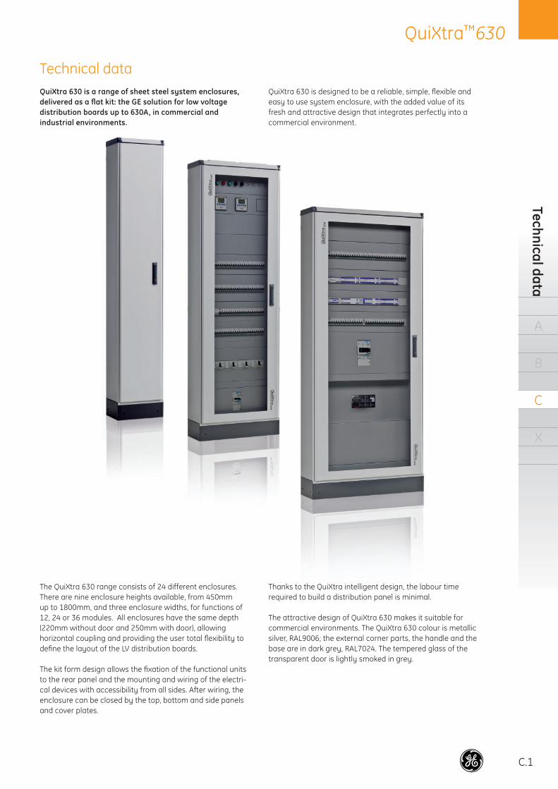
Technical dataQuiXtra 630 is a range of sheet steel system enclosures, delivered as a fl at kit: the GE solution for low voltage distribution boards up to 630A, in commercial and industrial environments.
QuiXtra 630 is designed to be a reliable, simple, fl exible and easy to use system enclosure, with the added value of its fresh and attractive design that integrates perfectly into a commercial environment.
The QuiXtra 630 range consists of 24 different enclosures. There are nine enclosure heights available, from 450mm up to 1800mm, and three enclosure widths, for functions of 12, 24 or 36 modules. All enclosures have the same depth (220mm without door and 250mm with door), allowing horizontal coupling and providing the user total fl exibility to defi ne the layout of the LV distribution boards.
The kit form design allows the fi xation of the functional units to the rear panel and the mounting and wiring of the electri-cal devices with accessibility from all sides. After wiring, the enclosure can be closed by the top, bottom and side panels and cover plates.
Thanks to the QuiXtra intelligent design, the labour time required to build a distribution panel is minimal.
The attractive design of QuiXtra 630 makes it suitable for commercial environments. The QuiXtra 630 colour is metallic silver, RAL9006; the external corner parts, the handle and the base are in dark grey, RAL7024. The tempered glass of the transparent door is lightly smoked in grey.
C.2
QuiXtra™630Te
chni
cal d
ata
A
B
C
X
Material and colourRear panel & mounting profi les Sendzimir zinc plated steel 1.5 mm
Side, top and bottom panel Epoxy-polyester coated sheet steel 1.25 mm
Plain door Epoxy-polyester coated sheet steel 1.25 mm
Transparent door Epoxy-polyester coated sheet steel 1.25 mm and smoked
safety glass 3 mm.
Cover plates Epoxy-polyester coated sheet steel 1 mm
External corner and coupling parts ABS
Internal corner plates Die-cast aluminium
Enclosure colour RAL 9006
Floor base colour RAL 7024
Main technical characteristics
Useful and external dimensions (mm)
Externalheight
Usefulheight
Rows150mm External width
Depthwith door
12 modules 24 modules 36 modules
600 450 3 - 660 - 250750 600 4 364 660 - 250900 750 5 364 660 876 250
1050 900 6 364 660 876 2501200 1050 7 364 660 876 2501350 1200 8 364 660 876 2501600 1350 9 364 660 876 2501750 1500 10 364 660 876 2502050 1800 12 364 660 876 250
(1) According to EN 61439-2: KEMA approval pending.
Protection degree and segregation formProtection class l
Pollution degree 2
Segregation Form 1 & Form 2
Protection degreeWithout door IP30, IK08
With plain door IP40, IK09
With plain door, IP43 profi le and IP43 kit IP43, IK09
With transparent door Same IP as plain door, IK08
Standards and approvalsStandards IEC 60439-1
EN 60439-1(1)
Approval with KEMA quality testreport
Certifi cation with KEMA quality testreport
RoHS Compliant
Electrical characteristicsRated current (In) 630 A
Rated operational voltage (Ue) 415 V
Rated insulation voltage (Ui) 690 V
Rated frequency (fn) 50/60 Hz
Rated short-circuit current (Icw) 30 kA/1s
Rated current of busbar systems 630 A in IP43
C.3
QuiXtra™630Enclosures
A
B
C
X
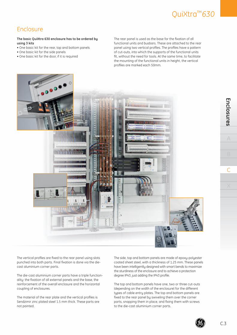
EnclosureThe basic QuiXtra 630 enclosure has to be ordered byusing 3 kits• One basic kit for the rear, top and bottom panels• One basic kit for the side panels• One basic kit for the door, if it is required
The rear panel is used as the base for the fi xation of all functional units and busbars. These are attached to the rear panel using two vertical profi les. The profi les have a pattern of cut-outs, into which the supports of the functional units fi t , without the need for tools. At the same time, to facilitate the mounting of the functional units in height, the vertical profi les are marked each 50mm.
The vertical profi les are fi xed to the rear panel using slots punched into both parts. Final fi xation is done via the die-cast aluminium corner parts.
The die-cast aluminium corner parts have a triple function-ality: the fi xation of all external panels and the base, the reinforcement of the overall enclosure and the horizontal coupling of enclosures.
The material of the rear plate and the vertical profi les is Sendzimir zinc plated steel 1.5 mm thick. These parts are not painted.
The side, top and bottom panels are made of epoxy-polyester coated sheet steel, with a thickness of 1.25 mm. These panels have been intelligently designed with smart bends to maximize the sturdiness of the enclosure and to achieve a protection degree IP43, just adding the IP43 profi le.
The top and bottom panels have one, two or three cut-outs (depending on the width of the enclosure) for the different types of cable entry plates. The top and bottom panels are fi xed to the rear panel by swiveling them over the corner parts, snapping them in place, and fi xing them with screws to the die-cast aluminium corner parts.
C.4
QuiXtra™630Te
chni
cal d
ata
A
B
C
X
Translation?
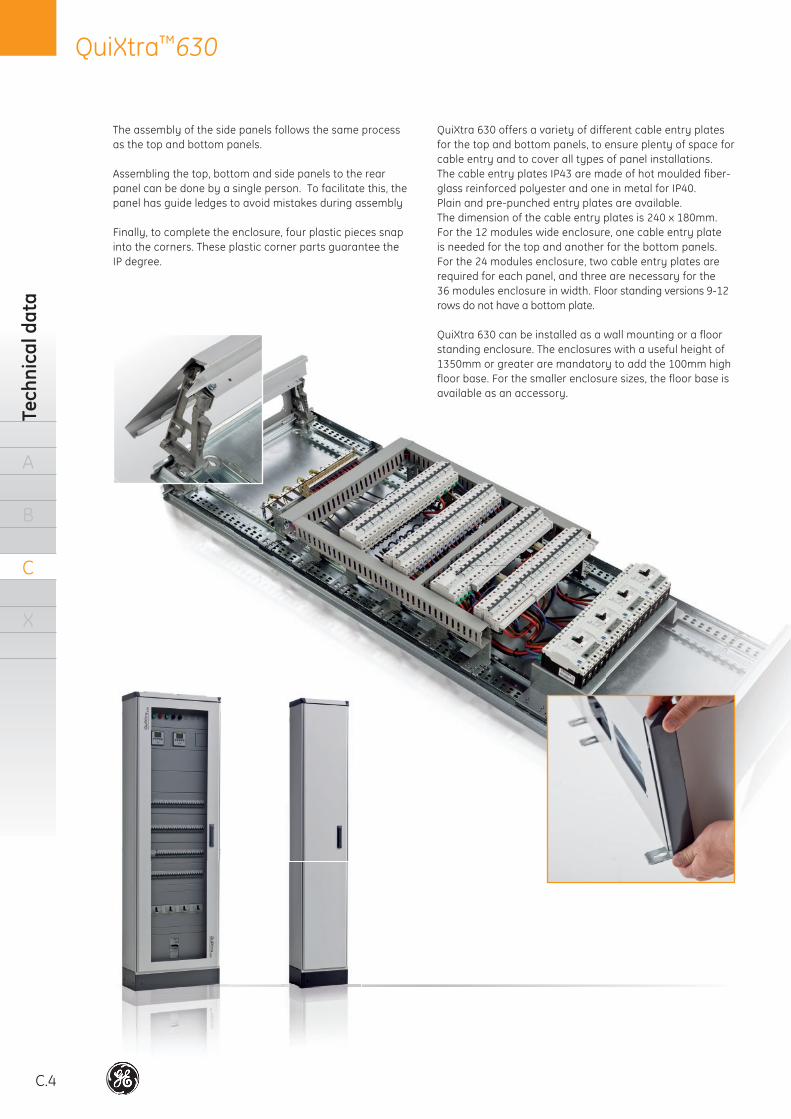
The assembly of the side panels follows the same process as the top and bottom panels.
Assembling the top, bottom and side panels to the rear panel can be done by a single person. To facilitate this, the panel has guide ledges to avoid mistakes during assembly
Finally, to complete the enclosure, four plastic pieces snap into the corners. These plastic corner parts guarantee the IP degree.
QuiXtra 630 offers a variety of different cable entry plates for the top and bottom panels, to ensure plenty of space for cable entry and to cover all types of panel installations. The cable entry plates IP43 are made of hot moulded fiber-glass reinforced polyester and one in metal for IP40. Plain and pre-punched entry plates are available. The dimension of the cable entry plates is 240 x 180mm. For the 12 modules wide enclosure, one cable entry plate is needed for the top and another for the bottom panels. For the 24 modules enclosure, two cable entry plates are required for each panel, and three are necessary for the 36 modules enclosure in width. Floor standing versions 9-12 rows do not have a bottom plate.
QuiXtra 630 can be installed as a wall mounting or a floor standing enclosure. The enclosures with a useful height of 1350mm or greater are mandatory to add the 100mm high floor base. For the smaller enclosure sizes, the floor base is available as an accessory.
TrTrTrTTrTrTTrTrTrTrTrTrTrTrTrTrTrTrTrTrTrTrTrTrTrTrTrTrTrrTrrTTrTTTTrTTrTrTrTrTrTTTTTTrTTTTTrTrTrTTTTTrTrTrTTTTTTTTrrTTTTrTrrTTTrTrTTTTTTTTTTTTTrTTTTrTTrrTTTTTTTTTT anaaaanaaaanananananaanaaaananaanaanaanaaaaanaaanaaaananaaannaannnnnnnnnnnnnnnnnnnnnnnnslslslslslsslslslssslslslslsllslssssssssssssssssssssslssssslatatatatatatatataatatatatatataatattaatatttttaatttaatttttttttatttttttaaatttttaaattttttattttttttttttttttttttaaattttttttatttaaaaatiiioiooiooiooiooiioioioioioioiioioiiiiiiioiiioiiioiooooooooooooooioooiiiooooiiioooooiiiioooon?n??n??n?n?n?n?n?n????n????nn????nn???n?n?n?n?n??n?n?n?n?nnnnn??n???n??nnnnnnn??????n?nnnnnn???n???nnnnnnnn??n?nnnnnnnnnnnnnnnnnnnnnnnnnnnn?nnnnnnnnnnn?nnnnnn?nnnnnnn??nnnnnnn??nnnnnn?nnnnnnn?nnn?nnn??n
standing enclosure. The enclosures with a useful height of 1350mm or greater are mandatory to add the 100mm high floor base. For the smaller enclosure sizes, the floor base is available as an accessory.
C.5
QuiXtra™630D
oor
A
B
C
X
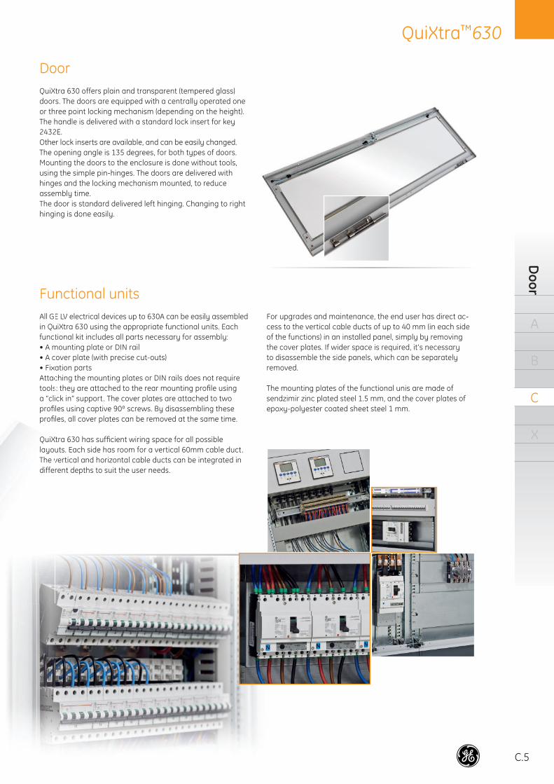
All GE LV electrical devices up to 630A can be easily assembled in QuiXtra 630 using the appropriate functional units. Each functional kit includes all parts necessary for assembly: • A mounting plate or DIN rail• A cover plate (with precise cut-outs) • Fixation partsAttaching the mounting plates or DIN rails does not require tools: they are attached to the rear mounting profi le using a “click in” support. The cover plates are attached to two profi les using captive 90º screws. By disassembling these profi les, all cover plates can be removed at the same time.
QuiXtra 630 has suffi cient wiring space for all possible layouts. Each side has room for a vertical 60mm cable duct. The vertical and horizontal cable ducts can be integrated in different depths to suit the user needs.
For upgrades and maintenance, the end user has direct ac-cess to the vertical cable ducts of up to 40 mm (in each side of the functions) in an installed panel, simply by removing the cover plates. If wider space is required, it's necessary to disassemble the side panels, which can be separately removed.
The mounting plates of the functional unis are made of sendzimir zinc plated steel 1.5 mm, and the cover plates of epoxy-polyester coated sheet steel 1 mm.
Door
Functional unitsAll GEin Qufunct• A m• A c• FixAttactoolsa “cliprofi profi
QQuiXlal youThe vdiffe
Fu
QuiXtra 630 offers plain and transparent (tempered glass) doors. The doors are equipped with a centrally operated one or three point locking mechanism (depending on the height). The handle is delivered with a standard lock insert for key 2432E. Other lock inserts are available, and can be easily changed. The opening angle is 135 degrees, for both types of doors. Mounting the doors to the enclosure is done without tools, using the simple pin-hinges. The doors are delivered with hinges and the locking mechanism mounted, to reduce assembly time.The door is standard delivered left hinging. Changing to right hinging is done easily.
C.6
QuiXtra™630Te
chni
cal d
ata
A
B
C
X
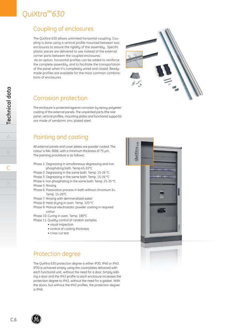
All external panels and cover plates are powder coated. The colour is RAL 9006, with a minimum thickness of 75 μm. The painting procedure is as follows:
Phase 1: Degreasing in simultaneous degreasing and iron phosphating bath. Temp.45-55°C
Phase 2: Degreasing in the same bath. Temp. 15-26 °CPhase 3: Degreasing in the same bath. Temp. 15-26 °CPhase 4: Iron phosphating in the same bath. Temp. 25-35 °CPhase 5: RinsingPhase 6: Passivation process in bath without chromium 6+.
Temp. 15-26°CPhase 7: Rinsing with demineralised waterPhase 8: Heat drying in oven. Temp. 120 °CPhase 9: Manual electrostatic powder coating in required
colourPhase 10: Curing in oven. Temp. 180°CPhase 11: Quality control of random samples
• visual inspection• control of coating thickness• cross cut test
The enclosure is protected against corrosion by epoxy polyester coating of the external panels. The unpainted parts (the rear panel, vertical profi les, mounting plates and functional supports) are made of sendzimir zinc plated steel.
Coupling of enclosures
Corrosion protection
Painting and coating
The QuiXtra 630 allows unlimited horizontal coupling. Cou-pling is done using a vertical profile mounted between two enclosures to assure the rigidity of the assembly. Specific plastic pieces are delivered to use instead of the external corner parts between the coupled enclosures. As an option, horizontal profiles can be added to reinforce the complete assembly, and to facilitate the transportation of the panel when it's completely wired and closed. Ready-made profiles are available for the most common combina-tions of enclosures.
The QuiXtra 630 protection degree is either IP30, IP40 or IP43. IP30 is achieved simply using the coverplates delivered with each functional unit, without the need for a door. Simply add-ing a door and the IP43 profi le to each enclosure increases the protection degree to IP43, without the need for a gasket. With the doors, but without the IP43 profi les, the protection degree is IP40.
Protection degree
C.7
QuiXtra™630Internal separation
A
B
C
X
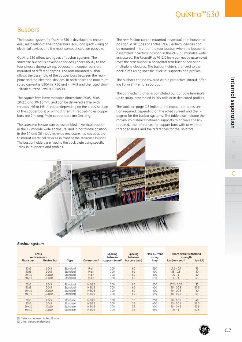
The busbar system for QuiXtra 630 is developed to ensure easy installation of the copper bars, easy and quick wiring of electrical devices and the most compact solution possible.
QuiXtra 630 offers two types of busbar systems. The staircase busbar is developed for easy accessibility to the four phases during wiring, because the copper bars are mounted at different depths. The rear mounted busbar allows the assembly of the copper bars between the rear-plate and the electrical devices. In both cases the maximum rated current is 630A in IP30 and in IP43 and the rated short -circuit current (Icw) is 30 kA/1s.
The copper bars have standard dimensions 20x5, 30x5, 20x10 and 30x10mm, and can be delivered either with threads (M6 or M8 threaded depending on the cross-section of the copper bars) or without them. Threaded-holes copper bars are 2m long. Plain copper bars are 3m long.
The staircase busbar can be assembled in vertical position in the 12 module wide enclosure, and in horizontal position in the 24 and 36 modules-wide enclosure. It's not possible to mount electrical devices in front of the staircase busbar. The busbar holders are fi xed to the back plate using specifi c “click in” supports and profiles.
The rear busbar can be mounted in vertical or in horizontal position in all types of enclosures. Electrical devices can be mounted in front of the rear busbar, when the busbar is assembled in vertical position in the 24 & 36 modules-wide enclosures. The RecordPlus FG & Dilos 4 can not be assembled over the rear busbar. A horizontal rear busbar can span multiple enclosures. The busbar holders are fixed to the back plate using specific “click in” supports and profiles.
The busbars can be covered with a protective shroud, offer-ing Form 2 internal separation.
The connectivity offer is completed by four pole terminals up to 400A, assembled in DIN rails or in dedicated profiles.
The table on page C.8 indicate the copper bar cross sec-tion required, depending on the rated current and the IP degree for the busbar systems. The table also indicate the maximum distance between supports to achieve the Icw required, the references for copper bars with or without threaded holes and the references for the isolators.
Busbars
Busbar system
Crosssection in mm
Phase bar Neutral bar Type Connection(1)
Spacing between
supports (mm)(2)
Spacing between
busbars (mm)
Max. CurrentratingAmp
Short-circuit withstandstrength
Icw (kA) - sec(2) Ipk (kA)
20x5 20x5 Standard Plain 300 60 250 17.5 - 0.7 3530x5 30x5 Standard Plain 300 60 400 25 - 0.8 50
20x10 20x10 Standard Plain 300 60 400 20 - 1 4030x10 30x10 Standard Plain 300 60 630 30 - 1 63
20x5 20x5 Standard M6/25 300 60 250 17.5 - 0.35 3530x5 30x5 Standard M6/25 300 60 400 25 - 0.35 52.5
20x10 20x10 Standard M6/25 300 60 400 20 - 0.75 4030x10 30x10 Standard M8/25 300 60 630 30 - 0.75 63
20x5 20x5 Staircase M6/25 300 35 250 20 - 0.35 4030x5 30x5 Staircase M6/25 300 35 400 25 - 0.35 52.5
20x10 20x10 Staircase M6/25 300 35 400 25 - 0.45 52.530x10 30x10 Staircase M8/25 300 35 630 25 - 1 52.5
(1) Distance between holes: 25 mm(2) Other values on demand
C.8
QuiXtra™630Te
chni
cal d
ata
A
B
C
X
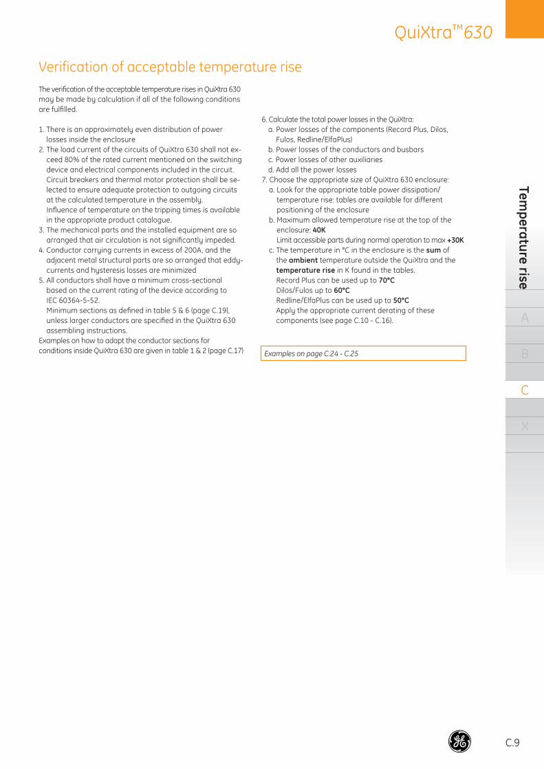
The earth continuity in QuiXtra 630 is assured via the screws that fi x the panels to the corner parts. Each special screw removes the paint in the contact area.
The earth continuity of the cover plates is guaranteed by removing the paint in the contact area with the enclosure.
Earthing concept
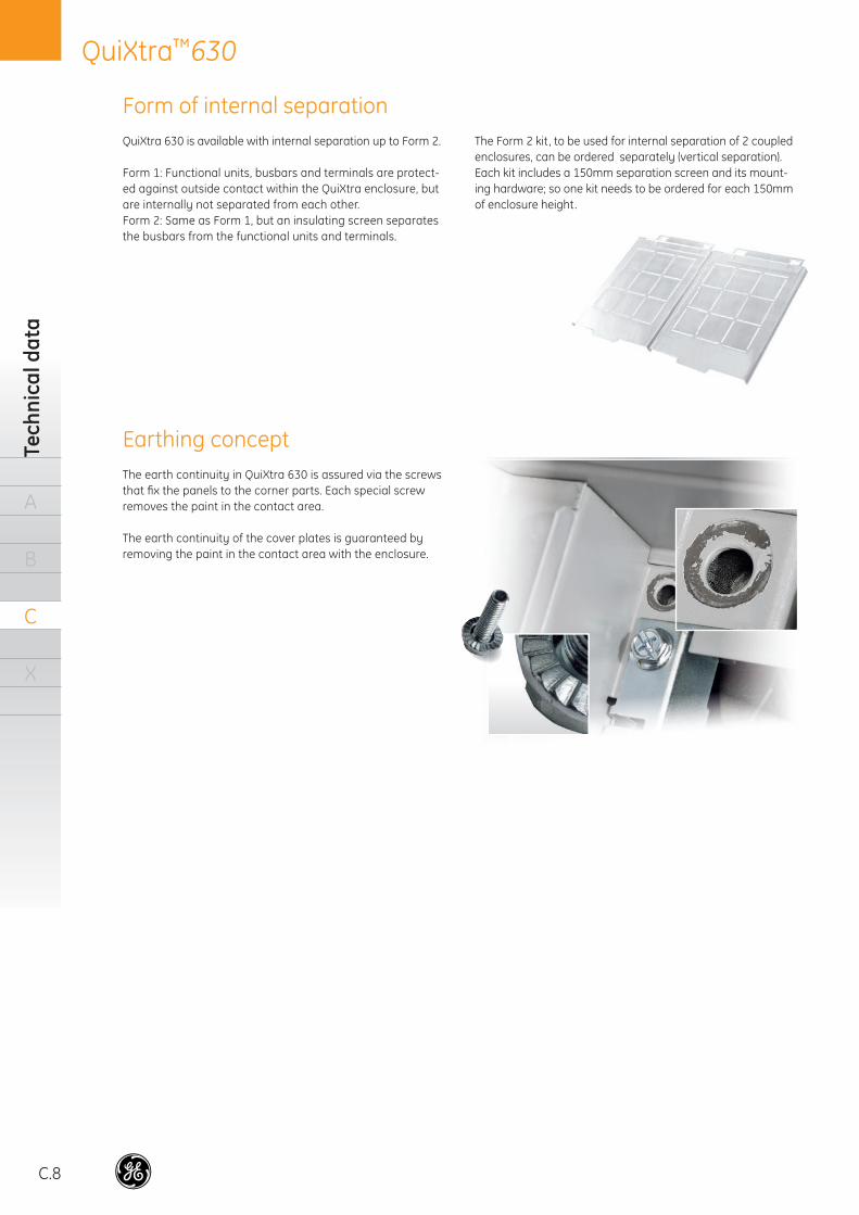
QuiXtra 630 is available with internal separation up to Form 2.
Form 1: Functional units, busbars and terminals are protect-ed against outside contact within the QuiXtra enclosure, but are internally not separated from each other.Form 2: Same as Form 1, but an insulating screen separates the busbars from the functional units and terminals.
The Form 2 kit, to be used for internal separation of 2 coupled enclosures, can be ordered separately (vertical separation). Each kit includes a 150mm separation screen and its mount-ing hardware; so one kit needs to be ordered for each 150mm of enclosure height.
Form of internal separation
C.9
QuiXtra™630Tem
perature rise
A
B
C
X
The verifi cation of the acceptable temperature rises in QuiXtra 630 may be made by calculation if all of the following conditions are fulfi lled.
1. There is an approximately even distribution of power losses inside the enclosure
2. The load current of the circuits of QuiXtra 630 shall not ex-ceed 80% of the rated current mentioned on the switching device and electrical components included in the circuit .Circuit breakers and thermal motor protection shall be se-lected to ensure adequate protection to outgoing circuits at the calculated temperature in the assembly. Infl uence of temperature on the tripping times is available in the appropriate product catalogue.
3. The mechanical parts and the installed equipment are so arranged that air circulation is not signifi cantly impeded.
4. Conductor carrying currents in excess of 200A, and the adjacent metal structural parts are so arranged that eddy-currents and hysteresis losses are minimized
5. All conductors shall have a minimum cross-sectional based on the current rating of the device according to IEC 60364-5-52.Minimum sections as defi ned in table 5 & 6 (page C.19), unless larger conductors are specifi ed in the QuiXtra 630 assembling instructions.
Examples on how to adapt the conductor sections for conditions inside QuiXtra 630 are given in table 1 & 2 (page C.17)
6. Calculate the total power losses in the QuiXtra:a. Power losses of the components (Record Plus, Dilos,
Fulos, Redline/ElfaPlus) b. Power losses of the conductors and busbarsc. Power losses of other auxiliariesd. Add all the power losses
7. Choose the appropriate size of QuiXtra 630 enclosure:a. Look for the appropriate table power dissipation/
temperature rise: tables are available for different positioning of the enclosure
b. Maximum allowed temperature rise at the top of the enclosure: 40KLimit accessible parts during normal operation to max +30K
c. The temperature in °C in the enclosure is the sum of the ambient temperature outside the QuiXtra and the temperature rise in K found in the tables.Record Plus can be used up to 70°CDilos/Fulos up to 60°CRedline/ElfaPlus can be used up to 50°CApply the appropriate current derating of these components (see page C.10 - C.16).
Verification of acceptable temperature rise
Examples on page C.24 - C.25
C.10
QuiXtra™630Te
chni
cal d
ata
A
B
C
X
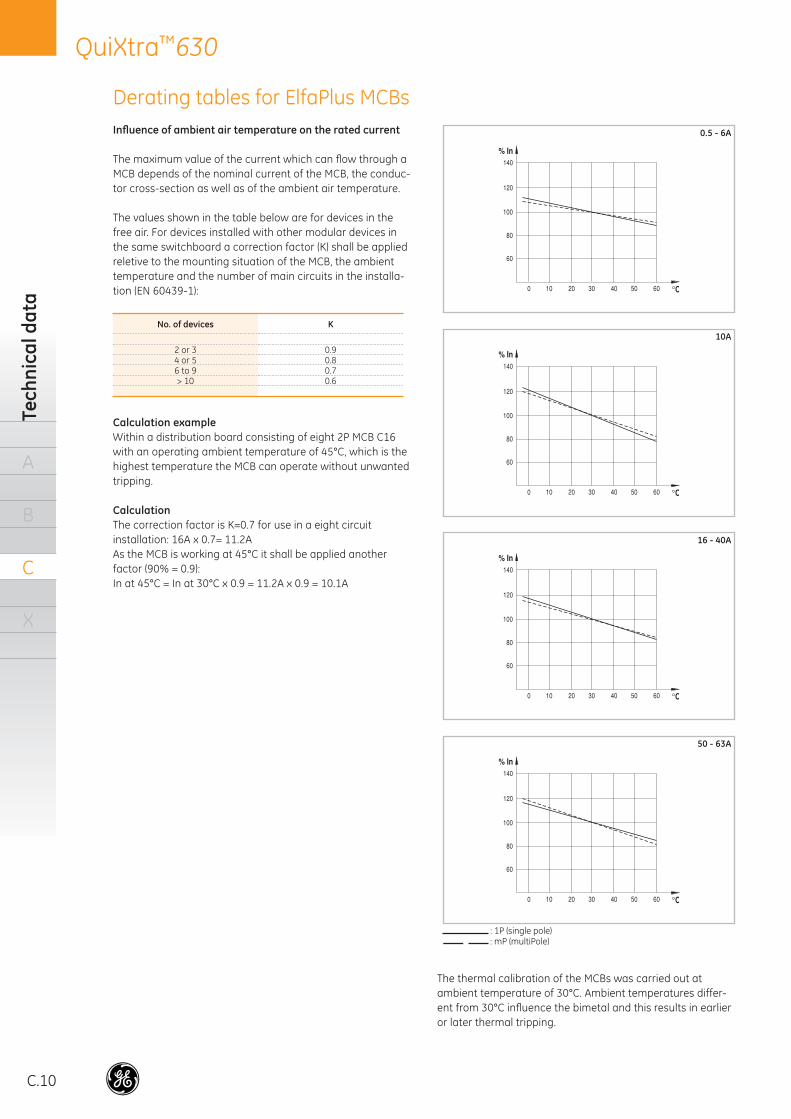
Infl uence of ambient air temperature on the rated current
The maximum value of the current which can fl ow through a MCB depends of the nominal current of the MCB, the conduc-tor cross-section as well as of the ambient air temperature.
The values shown in the table below are for devices in the free air. For devices installed with other modular devices in the same switchboard a correction factor (K) shall be applied reletive to the mounting situation of the MCB, the ambient temperature and the number of main circuits in the installa-tion (EN 60439-1):
No. of devices K
2 or 3 0.94 or 5 0.86 to 9 0.7> 10 0.6
Calculation exampleWithin a distribution board consisting of eight 2P MCB C16 with an operating ambient temperature of 45°C, which is the highest temperature the MCB can operate without unwanted tripping.
CalculationThe correction factor is K=0.7 for use in a eight circuit installation: 16A x 0.7= 11.2AAs the MCB is working at 45°C it shall be applied another factor (90% = 0.9):In at 45°C = In at 30°C x 0.9 = 11.2A x 0.9 = 10.1A
The thermal calibration of the MCBs was carried out at ambient temperature of 30°C. Ambient temperatures differ-ent from 30°C infl uence the bimetal and this results in earlier or later thermal tripping.
: 1P (single pole) : mP (multiPole)
0.5 - 6A
10A
16 - 40A
50 - 63A
Derating tables for ElfaPlus MCBs
C.11
QuiXtra™630D
erating tables
A
B
C
X
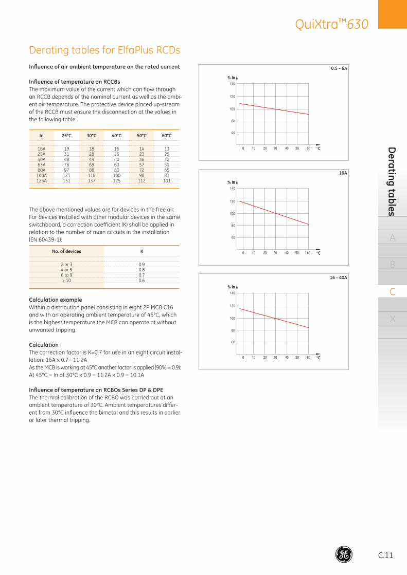
Infl uence of air ambient temperature on the rated current
Infl uence of temperature on RCCBsThe maximum value of the current which can fl ow through an RCCB depends of the nominal current as well as the ambi-ent air temperature. The protective device placed up-stream of the RCCB must ensure the disconnection at the values in the following table:
In 25°C 30°C 40°C 50°C 60°C
16A 19 18 16 14 1325A 31 28 25 23 2540A 48 44 40 36 3263A 76 69 63 57 5180A 97 88 80 72 65
100A 121 110 100 90 81125A 151 137 125 112 101
The above mentioned values are for devices in the free air. For devices installed with other modular devices in the same switchboard, a correction coeffi cient (K) shall be applied in relation to the number of main circuits in the installation(EN 60439-1):
No. of devices K
2 or 3 0.94 or 5 0.86 to 9 0.7> 10 0.6
Calculation exampleWithin a distribution panel consisting in eight 2P MCB C16 and with an operating ambient temperature of 45°C, which is the highest temperature the MCB can operate at without unwanted tripping.
CalculationThe correction factor is K=0.7 for use in an eight circuit instal-lation: 16A x 0.7= 11.2AAs the MCB is working at 45°C another factor is applied (90% = 0.9):At 45°C = In at 30°C x 0.9 = 11.2A x 0.9 = 10.1A
Infl uence of temperature on RCBOs Series DP & DPEThe thermal calibration of the RCBO was carried out at an ambient temperature of 30°C. Ambient temperatures differ-ent from 30°C infl uence the bimetal and this results in earlier or later thermal tripping.
0.5 - 6A
10A
16 - 40A
Derating tables for ElfaPlus RCDs
C.12
QuiXtra™630Te
chni
cal d
ata
A
B
C
X
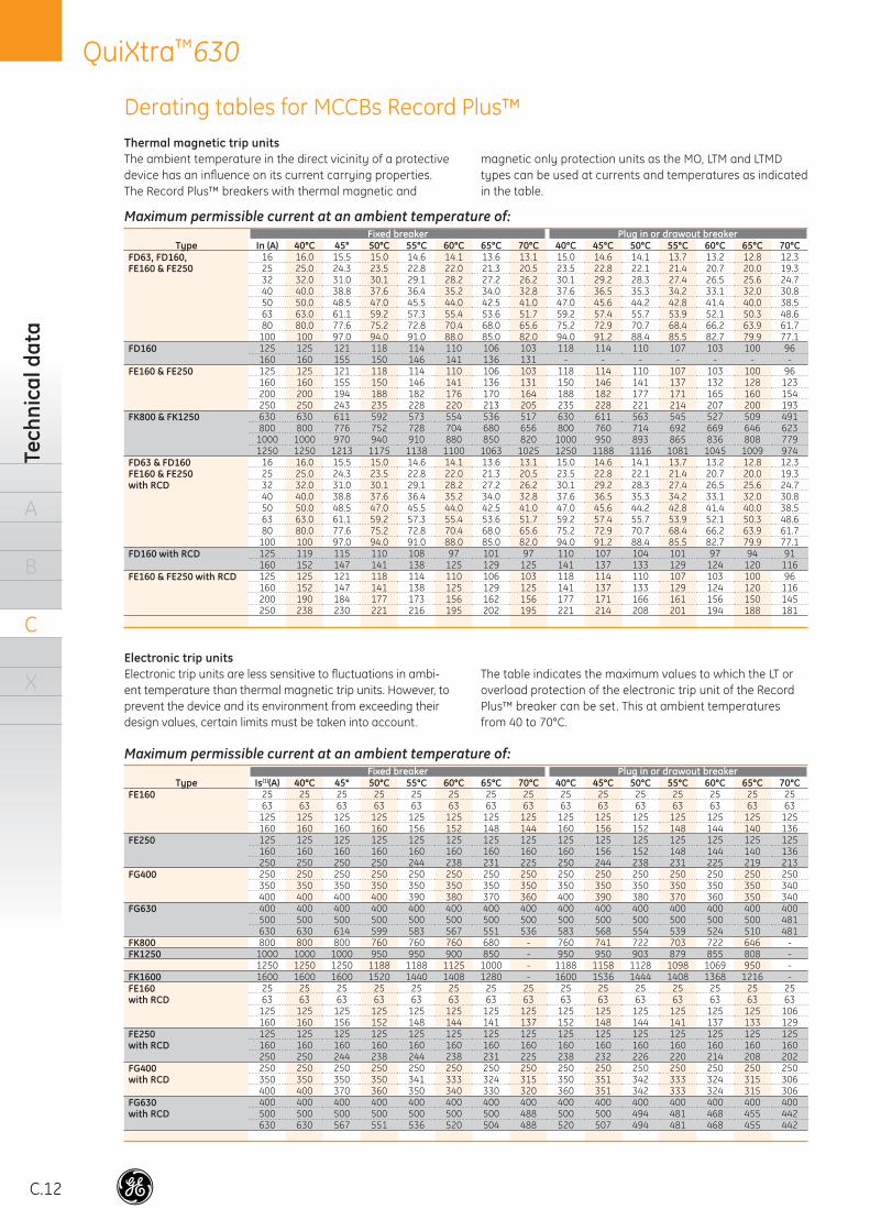
Thermal magnetic trip unitsThe ambient temperature in the direct vicinity of a protective device has an infl uence on its current carrying properties. The Record Plus™ breakers with thermal magnetic and
magnetic only protection units as the MO, LTM and LTMD types can be used at currents and temperatures as indicated in the table.
Electronic trip unitsElectronic trip units are less sensitive to fl uctuations in ambi-ent temperature than thermal magnetic trip units. However, to prevent the device and its environment from exceeding their design values, certain limits must be taken into account.
The table indicates the maximum values to which the LT or overload protection of the electronic trip unit of the Record Plus™ breaker can be set. This at ambient temperatures from 40 to 70°C.
Maximum permissible current at an ambient temperature of:Fixed breaker Plug in or drawout breaker
Type In (A) 40°C 45° 50°C 55°C 60°C 65°C 70°C 40°C 45°C 50°C 55°C 60°C 65°C 70°CFD63, FD160, 16 16.0 15.5 15.0 14.6 14.1 13.6 13.1 15.0 14.6 14.1 13.7 13.2 12.8 12.3FE160 & FE250 25 25.0 24.3 23.5 22.8 22.0 21.3 20.5 23.5 22.8 22.1 21.4 20.7 20.0 19.3
32 32.0 31.0 30.1 29.1 28.2 27.2 26.2 30.1 29.2 28.3 27.4 26.5 25.6 24.740 40.0 38.8 37.6 36.4 35.2 34.0 32.8 37.6 36.5 35.3 34.2 33.1 32.0 30.850 50.0 48.5 47.0 45.5 44.0 42.5 41.0 47.0 45.6 44.2 42.8 41.4 40.0 38.563 63.0 61.1 59.2 57.3 55.4 53.6 51.7 59.2 57.4 55.7 53.9 52.1 50.3 48.680 80.0 77.6 75.2 72.8 70.4 68.0 65.6 75.2 72.9 70.7 68.4 66.2 63.9 61.7
100 100 97.0 94.0 91.0 88.0 85.0 82.0 94.0 91.2 88.4 85.5 82.7 79.9 77.1FD160 125 125 121 118 114 110 106 103 118 114 110 107 103 100 96
160 160 155 150 146 141 136 131 - - - - - - -FE160 & FE250 125 125 121 118 114 110 106 103 118 114 110 107 103 100 96
160 160 155 150 146 141 136 131 150 146 141 137 132 128 123200 200 194 188 182 176 170 164 188 182 177 171 165 160 154250 250 243 235 228 220 213 205 235 228 221 214 207 200 193
FK800 & FK1250 630 630 611 592 573 554 536 517 630 611 563 545 527 509 491800 800 776 752 728 704 680 656 800 760 714 692 669 646 623
1000 1000 970 940 910 880 850 820 1000 950 893 865 836 808 7791250 1250 1213 1175 1138 1100 1063 1025 1250 1188 1116 1081 1045 1009 974
FD63 & FD160 16 16.0 15.5 15.0 14.6 14.1 13.6 13.1 15.0 14.6 14.1 13.7 13.2 12.8 12.3FE160 & FE250 25 25.0 24.3 23.5 22.8 22.0 21.3 20.5 23.5 22.8 22.1 21.4 20.7 20.0 19.3with RCD 32 32.0 31.0 30.1 29.1 28.2 27.2 26.2 30.1 29.2 28.3 27.4 26.5 25.6 24.7
40 40.0 38.8 37.6 36.4 35.2 34.0 32.8 37.6 36.5 35.3 34.2 33.1 32.0 30.850 50.0 48.5 47.0 45.5 44.0 42.5 41.0 47.0 45.6 44.2 42.8 41.4 40.0 38.563 63.0 61.1 59.2 57.3 55.4 53.6 51.7 59.2 57.4 55.7 53.9 52.1 50.3 48.680 80.0 77.6 75.2 72.8 70.4 68.0 65.6 75.2 72.9 70.7 68.4 66.2 63.9 61.7
100 100 97.0 94.0 91.0 88.0 85.0 82.0 94.0 91.2 88.4 85.5 82.7 79.9 77.1FD160 with RCD 125 119 115 110 108 97 101 97 110 107 104 101 97 94 91
160 152 147 141 138 125 129 125 141 137 133 129 124 120 116FE160 & FE250 with RCD 125 125 121 118 114 110 106 103 118 114 110 107 103 100 96
160 152 147 141 138 125 129 125 141 137 133 129 124 120 116200 190 184 177 173 156 162 156 177 171 166 161 156 150 145250 238 230 221 216 195 202 195 221 214 208 201 194 188 181
Maximum permissible current at an ambient temperature of:Fixed breaker Plug in or drawout breaker
Type Is(1)(A) 40°C 45° 50°C 55°C 60°C 65°C 70°C 40°C 45°C 50°C 55°C 60°C 65°C 70°CFE160 25 25 25 25 25 25 25 25 25 25 25 25 25 25 25
63 63 63 63 63 63 63 63 63 63 63 63 63 63 63125 125 125 125 125 125 125 125 125 125 125 125 125 125 125160 160 160 160 156 152 148 144 160 156 152 148 144 140 136
FE250 125 125 125 125 125 125 125 125 125 125 125 125 125 125 125160 160 160 160 160 160 160 160 160 156 152 148 144 140 136250 250 250 250 244 238 231 225 250 244 238 231 225 219 213
FG400 250 250 250 250 250 250 250 250 250 250 250 250 250 250 250350 350 350 350 350 350 350 350 350 350 350 350 350 350 340400 400 400 400 390 380 370 360 400 390 380 370 360 350 340
FG630 400 400 400 400 400 400 400 400 400 400 400 400 400 400 400500 500 500 500 500 500 500 500 500 500 500 500 500 500 481630 630 614 599 583 567 551 536 583 568 554 539 524 510 481
FK800 800 800 800 760 760 760 680 - 760 741 722 703 722 646 -FK1250 1000 1000 1000 950 950 900 850 - 950 950 903 879 855 808 -
1250 1250 1250 1188 1188 1125 1000 - 1188 1158 1128 1098 1069 950 -FK1600 1600 1600 1600 1520 1440 1408 1280 - 1600 1536 1444 1408 1368 1216 -FE160 25 25 25 25 25 25 25 25 25 25 25 25 25 25 25with RCD 63 63 63 63 63 63 63 63 63 63 63 63 63 63 63
125 125 125 125 125 125 125 125 125 125 125 125 125 125 106160 160 156 152 148 144 141 137 152 148 144 141 137 133 129
FE250 125 125 125 125 125 125 125 125 125 125 125 125 125 125 125with RCD 160 160 160 160 160 160 160 160 160 160 160 160 160 160 160
250 250 244 238 244 238 231 225 238 232 226 220 214 208 202FG400 250 250 250 250 250 250 250 250 250 250 250 250 250 250 250with RCD 350 350 350 350 341 333 324 315 350 351 342 333 324 315 306
400 400 370 360 350 340 330 320 360 351 342 333 324 315 306FG630 400 400 400 400 400 400 400 400 400 400 400 400 400 400 400with RCD 500 500 500 500 500 500 500 488 500 500 494 481 468 455 442
630 630 567 551 536 520 504 488 520 507 494 481 468 455 442
Derating tables for MCCBs Record Plus™
C.13
QuiXtra™630D
erating tables
A
B
C
X
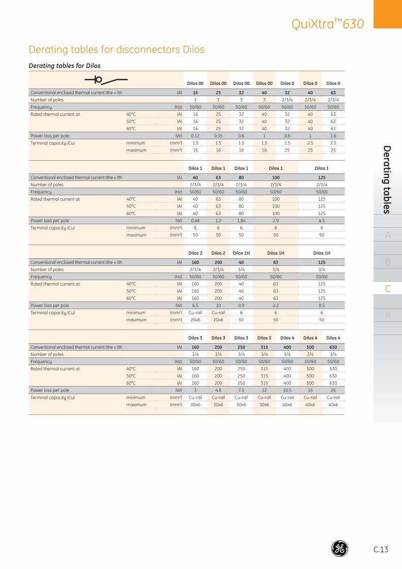
Derating tables for Dilos
Dilos 00 Dilos 00 Dilos 00 Dilos 00 Dilos 0 Dilos 0 Dilos 0
Conventional enclosed thermal current Ithe = Ith (A) 16 25 32 40 32 40 63Number of poles 3 3 3 3 2/3/4 2/3/4 2/3/4
Frequency (Hz) 50/60 50/60 50/60 50/60 50/60 50/60 50/60
Rated thermal current at 40°C (A) 16 25 32 40 32 40 63
50°C (A) 16 25 32 40 32 40 63
60°C (A) 16 25 32 40 32 40 63
Power loss per pole (W) 0.12 0.35 0.6 1 0.6 1 1.6
Terminal capacity (Cu) minimum (mm²) 1.5 1.5 1.5 1.5 2.5 2.5 2.5
maximum (mm²) 16 16 16 16 25 25 25
Dilos 1 Dilos 1 Dilos 1 Dilos 1 Dilos 1
Conventional enclosed thermal current Ithe = Ith (A) 40 63 80 100 125Number of poles 2/3/4 2/3/4 2/3/4 2/3/4 2/3/4
Frequency (Hz) 50/60 50/60 50/60 50/60 50/60
Rated thermal current at 40°C (A) 40 63 80 100 125
50°C (A) 40 63 80 100 125
60°C (A) 40 63 80 100 125
Power loss per pole (W) 0.48 1.2 1.84 2.9 4.5
Terminal capacity (Cu) minimum (mm²) 6 6 6 6 6
maximum (mm²) 50 50 50 50 50
Dilos 2 Dilos 2 Dilos 1H Dilos 1H Dilos 1H
Conventional enclosed thermal current Ithe = Ith (A) 160 200 40 63 125Number of poles 2/3/4 2/3/4 3/4 3/4 3/4
Frequency (Hz) 50/60 50/60 50/60 50/60 50/60
Rated thermal current at 40°C (A) 160 200 40 63 125
50°C (A) 160 200 40 63 125
60°C (A) 160 200 40 63 125
Power loss per pole (W) 6.5 10 0.9 2.2 8.5
Terminal capacity (Cu) minimum (mm²) Cu-rail Cu-rail 6 6 6
maximum (mm²) 20x6 20x6 50 50 50
Dilos 3 Dilos 3 Dilos 3 Dilos 3 Dilos 4 Dilos 4 Dilos 4
Conventional enclosed thermal current Ithe = Ith (A) 160 200 250 315 400 500 630Number of poles 3/4 3/4 3/4 3/4 3/4 3/4 3/4
Frequency (Hz) 50/60 50/60 50/60 50/60 50/60 50/60 50/60
Rated thermal current at 40°C (A) 160 200 250 315 400 500 630
50°C (A) 160 200 250 315 400 500 630
60°C (A) 160 200 250 315 400 500 630
Power loss per pole (W) 3 4.8 7.5 12 10.5 16 26
Terminal capacity (Cu) minimum (mm²) Cu-rail Cu-rail Cu-rail Cu-rail Cu-rail Cu-rail Cu-rail
maximum (mm²) 30x6 30x6 30x6 30x6 40x6 40x6 40x6
Derating tables for disconnectors Dilos
C.14
QuiXtra™630Te
chni
cal d
ata
A
B
C
X
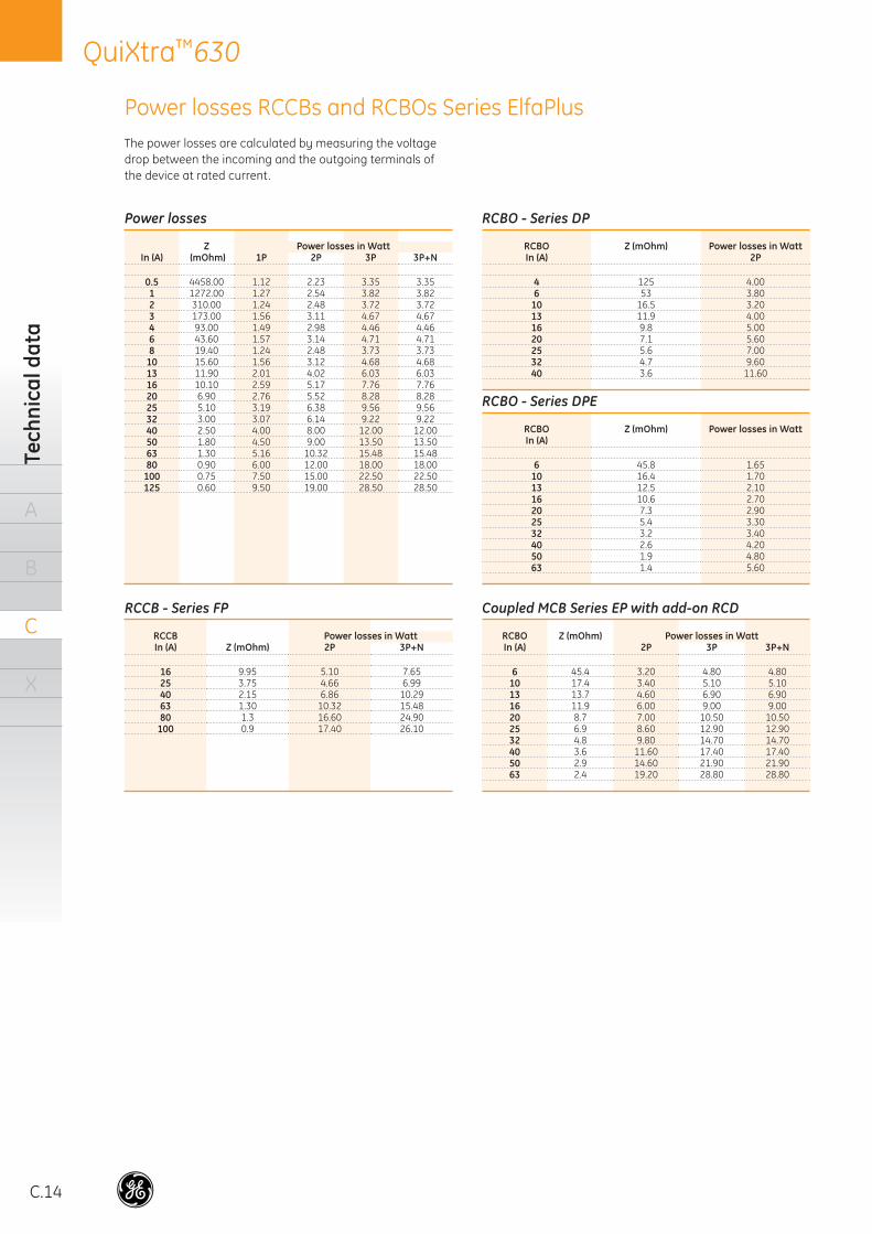
The power losses are calculated by measuring the voltage drop between the incoming and the outgoing terminals of the device at rated current.
Power losses
Z Power losses in WattIn (A) (mOhm) 1P 2P 3P 3P+N
0.5 4458.00 1.12 2.23 3.35 3.351 1272.00 1.27 2.54 3.82 3.822 310.00 1.24 2.48 3.72 3.723 173.00 1.56 3.11 4.67 4.674 93.00 1.49 2.98 4.46 4.466 43.60 1.57 3.14 4.71 4.718 19.40 1.24 2.48 3.73 3.73
10 15.60 1.56 3.12 4.68 4.6813 11.90 2.01 4.02 6.03 6.0316 10.10 2.59 5.17 7.76 7.7620 6.90 2.76 5.52 8.28 8.2825 5.10 3.19 6.38 9.56 9.5632 3.00 3.07 6.14 9.22 9.2240 2.50 4.00 8.00 12.00 12.0050 1.80 4.50 9.00 13.50 13.5063 1.30 5.16 10.32 15.48 15.4880 0.90 6.00 12.00 18.00 18.00
100 0.75 7.50 15.00 22.50 22.50125 0.60 9.50 19.00 28.50 28.50
RCCB - Series FP
RCCB Power losses in WattIn (A) Z (mOhm) 2P 3P+N
16 9.95 5.10 7.6525 3.75 4.66 6.9940 2.15 6.86 10.2963 1.30 10.32 15.4880 1.3 16.60 24.90
100 0.9 17.40 26.10
RCBO - Series DP
RCBO Z (mOhm) Power losses in WattIn (A) 2P
4 125 4.006 53 3.80
10 16.5 3.2013 11.9 4.0016 9.8 5.0020 7.1 5.6025 5.6 7.0032 4.7 9.6040 3.6 11.60
RCBO - Series DPE
RCBO Z (mOhm) Power losses in WattIn (A)
6 45.8 1.6510 16.4 1.7013 12.5 2.1016 10.6 2.7020 7.3 2.9025 5.4 3.3032 3.2 3.4040 2.6 4.2050 1.9 4.8063 1.4 5.60
Coupled MCB Series EP with add-on RCD
RCBO Z (mOhm) Power losses in WattIn (A) 2P 3P 3P+N
6 45.4 3.20 4.80 4.8010 17.4 3.40 5.10 5.1013 13.7 4.60 6.90 6.9016 11.9 6.00 9.00 9.0020 8.7 7.00 10.50 10.5025 6.9 8.60 12.90 12.9032 4.8 9.80 14.70 14.7040 3.6 11.60 17.40 17.4050 2.9 14.60 21.90 21.9063 2.4 19.20 28.80 28.80
Power losses RCCBs and RCBOs Series ElfaPlus
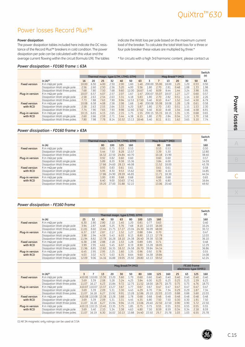
C.15
QuiXtra™630Pow
er losses
A
B
C
X
Power dissipation - FD160 frame ≤ 63ASwitch
(Y)Thermal magn. type (LTM, LTMD, GTM) Mag Break™ (MO)In (A)(1) 16 20 25 32 40 50 63 3 7 13 20 30 50 63
Fixed version R in mΩ per pole 10.00 6.50 4.00 2.50 2.00 1.60 1.40 200.00 55.00 18.00 1.20 1.20 0.53 0.50Dissipation Watt single pole 2.56 2.60 2.50 2.56 3.20 4.00 5.56 1.80 2.70 2.81 0.48 1.08 1.33 1.98Dissipation Watt three poles 7.68 7.80 7.50 7.68 9.60 12.00 16.67 5.40 8.09 8.44 1.44 3.24 3.98 5.95
Plug-in version R in mΩ per pole 10.07 6.57 4.07 2.57 2.07 1.67 1.47 200.07 55.07 18.07 1.27 1.27 0.60 0.57Dissipation Watt single pole 2.58 2.63 2.54 2.63 3.31 4.18 5.83 1.80 2.70 2.82 0.51 1.14 1.50 2.26Dissipation Watt three poles 7.73 7.88 7.63 7.90 9.94 12.53 17.50 5.40 8.10 8.47 1.52 3.43 4.50 6.79
Fixed version R in mΩ per pole 10.08 6.58 4.08 2.58 2.08 1.68 1.48 200.08 55.08 18.08 1.28 1.28 0.61 0.58with RCD Dissipation Watt single pole 2.58 2.63 2.55 2.64 3.33 4.20 5.87 1.80 2.70 2.83 0.51 1.15 1.53 2.30
Dissipation Watt three poles 7.74 7.90 7.65 7.93 9.98 12.60 17.62 5.40 8.10 8.48 1.54 3.46 4.58 6.91Plug-in version R in mΩ per pole 10.15 6.65 4.15 2.65 2.15 1.75 1.55 200.15 55.15 18.15 1.35 1.35 0.68 0.65
with RCD Dissipation Watt single pole 2.60 2.66 2.59 2.71 3.44 4.38 6.15 1.80 2.70 2.84 0.54 1.22 1.70 2.58Dissipation Watt three poles 7.80 7.98 7.78 8.14 10.32 13.13 18.46 5.40 8.11 8.51 1.62 3.65 5.10 7.74
Power dissipation - FD160 frame > 63ASwitch
(Y)Thermal magn. type (LTM, LTMD, GTM) Mag Break™ (MO)In (A) 80 100 125 160 80 100 160
Fixed version R in mΩ per pole 0.85 0.75 0.53 0.53 0.53 0.53 0.50Dissipation Watt single pole 5.44 7.50 8.28 13.57 3.39 5.30 12.80Dissipation Watt three poles 16.32 22.50 24.84 40.70 10.18 15.90 38.40
Plug-in version R in mΩ per pole 0.92 0.82 0.60 0.60 0.60 0.60 0.57Dissipation Watt single pole 5.89 8.20 9.38 15.36 3.84 6.00 14.59Dissipation Watt three poles 17.66 24.60 28.13 46.08 11.52 18.00 43.78
Fixed version R in mΩ per pole 0.93 0.83 0.61 0.61 0.61 0.61 0.58with RCD Dissipation Watt single pole 5.95 8.30 9.53 15.62 3.90 6.10 14.85
Dissipation Watt three poles 17.86 24.90 28.59 46.85 11.71 18.30 44.54Plug-in version R in mΩ per pole 1.00 0.90 0.68 0.68 0.68 0.68 0.65
with RCD Dissipation Watt single pole 6.40 9.00 10.63 17.41 4.35 6.80 16.64Dissipation Watt three poles 19.20 27.00 31.88 52.22 13.06 20.40 49.92
Power dissipation - FE160 frameSwitch
(Y)Thermal magn. type (LTMD, GTM)In (A) 25 32 40 50 63 80 100 125 160 160
Fixed version R in mΩ per pole 6.30 2.80 2.80 2.10 1.45 1.20 0.81 0.77 0.63 0.40Dissipation Watt single pole 3.94 2.87 4.48 5.25 5.76 7.68 8.10 12.03 16.00 10.24Dissipation Watt three poles 11.81 8.60 13.44 15.75 17.27 23.04 24.30 36.09 48.00 30.72
Plug-in version R in mΩ per pole 6.37 2.87 2.87 2.17 1.52 1.27 0.88 0.84 0.70 0.47Dissipation Watt single pole 3.98 2.94 4.59 5.43 6.03 8.13 8.80 13.13 17.79 12.03Dissipation Watt three poles 11.94 8.82 13.78 16.28 18.10 24.38 26.40 39.38 53.38 36.10
Fixed version R in mΩ per pole 6.38 2.88 2.88 2.18 1.53 1.28 0.89 0.85 0.71 0.48with RCD Dissipation Watt single pole 3.99 2.95 4.61 5.45 6.07 8.19 8.90 13.28 18.05 12.29
Dissipation Watt three poles 11.96 8.85 13.82 16.35 18.22 24.58 26.70 39.84 54.14 36.86Plug-in version R in mΩ per pole 6.45 2.95 2.95 2.25 1.60 1.35 0.96 0.92 0.78 0.55
with RCD Dissipation Watt single pole 4.03 3.02 4.72 5.63 6.35 8.64 9.60 14.38 19.84 14.08Dissipation Watt three poles 12.09 9.06 14.16 16.88 19.05 25.92 28.80 43.13 59.52 42.24
Mag BreakTM (MO) FE160 frameelectronic type (SMR1)
In (A)(1) 3 7 13 20 30 50 80 100 125 160 25 63 125 160Fixed version R in mΩ per pole 410.00 110.00 13.30 13.20 3.60 1.70 0.60 0.60 0.40 0.40 0.40 0.40 0.40 0.40
Dissipation Watt single pole 3.69 5.39 2.08 5.28 3.24 4.25 3.84 6.00 6.25 6.25 0.25 0.25 1.59 6.25Dissipation Watt three poles 11.07 16.17 6.23 15.84 9.72 12.75 11.52 18.00 18.75 18.75 0.75 0.75 4.76 18.75
Plug-in version R in mΩ per pole 410.07 110.07 13.37 13.27 3.67 1.77 0.67 0.67 0.47 0.47 0.47 0.47 0.47 0.47Dissipation Watt single pole 3.69 5.39 2.09 5.31 3.30 4.43 4.29 6.70 7.34 7.34 0.29 0.29 1.87 7.34Dissipation Watt three poles 11.07 16.18 6.27 15.92 9.91 13.28 12.86 20.10 22.03 22.03 0.88 0.88 5.60 22.03
Fixed version R in mΩ per pole 410.08 110.08 13.38 13.28 3.68 1.78 0.68 0.68 0.48 0.48 0.48 0.48 0.48 0.48with RCD Dissipation Watt single pole 3.69 5.39 2.09 5.31 3.31 4.45 4.35 6.80 7.50 7.50 0.30 0.30 1.91 7.50
Dissipation Watt three poles 11.07 16.18 6.27 15.94 9.94 13.35 13.06 20.40 22.50 22.50 0.90 0.90 5.72 22.50Plug-in version R in mΩ per pole 410.15 110.15 13.45 13.35 3.75 1.85 0.75 0.75 0.55 0.55 0.55 0.55 0.55 0.55
with RCD Dissipation Watt single pole 3.69 5.40 2.10 5.34 3.38 4.63 4.80 7.50 8.59 8.59 0.34 0.34 2.18 8.59Dissipation Watt three poles 11.07 16.19 6.30 16.02 10.13 13.88 14.40 22.50 25.7 25.78 1.03 1.03 6.55 25.78
(1) All 3A magnetic only ratings can be used at 3.5A
Power dissipationThe power dissipation tables included here indicate the DC resis-tance of the Record Plus™ breakers in cold condition. The power dissipation per pole can be calculated with this value and the average current fl owing within the circuit (formula I2R). The tables
indicate the Watt loss per pole based on the maximum current load of the breaker. To calculate the total Watt loss for a three or four pole breaker these values are multiplied by three.*
* for circuits with a high 3rd harmonic content, please contact us
Power losses Record Plus™
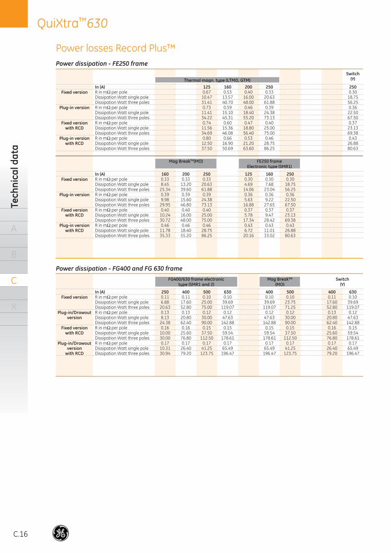
C.16
QuiXtra™630Te
chni
cal d
ata
A
B
C
X
Power dissipation - FE250 frameSwitch
(Y)Thermal magn. type (LTMD, GTM)In (A) 125 160 200 250 250
Fixed version R in mΩ per pole 0.67 0.53 0.40 0.33 0.30Dissipation Watt single pole 10.47 13.57 16.00 20.63 18.75Dissipation Watt three poles 31.41 40.70 48.00 61.88 56.25
Plug-in version R in mΩ per pole 0.73 0.59 0.46 0.39 0.36Dissipation Watt single pole 11.41 15.10 18.40 24.38 22.50Dissipation Watt three poles 34.22 45.31 55.20 73.13 67.50
Fixed version R in mΩ per pole 0.74 0.60 0.47 0.40 0.37with RCD Dissipation Watt single pole 11.56 15.36 18.80 25.00 23.13
Dissipation Watt three poles 34.69 46.08 56.40 75.00 69.38Plug-in version R in mΩ per pole 0.80 0.66 0.53 0.46 0.43
with RCD Dissipation Watt single pole 12.50 16.90 21.20 28.75 26.88Dissipation Watt three poles 37.50 50.69 63.60 86.25 80.63
Mag BreakTM(MO) FE250 frameElectronic type (SMR1)
In (A) 160 200 250 125 160 250Fixed version R in mΩ per pole 0.33 0.33 0.33 0.30 0.30 0.30
Dissipation Watt single pole 8.45 13.20 20.63 4.69 7.68 18.75Dissipation Watt three poles 25.34 39.60 61.88 14.06 23.04 56.25
Plug-in version R in mΩ per pole 0.39 0.39 0.39 0.36 0.36 0.36Dissipation Watt single pole 9.98 15.60 24.38 5.63 9.22 22.50Dissipation Watt three poles 29.95 46.80 73.13 16.88 27.65 67.50
Fixed version R in mΩ per pole 0.40 0.40 0.40 0.37 0.37 0.37with RCD Dissipation Watt single pole 10.24 16.00 25.00 5.78 9.47 23.13
Dissipation Watt three poles 30.72 48.00 75.00 17.34 28.42 69.38Plug-in version R in mΩ per pole 0.46 0.46 0.46 0.43 0.43 0.43
with RCD Dissipation Watt single pole 11.78 18.40 28.75 6.72 11.01 26.88Dissipation Watt three poles 35.33 55.20 86.25 20.16 33.02 80.63
Power dissipation - FG400 and FG 630 frameFG400/630 frame electronic
type (SMR1 and 2)Mag Break™
(MO)Switch
(Y)
In (A) 250 400 500 630 400 500 400 630Fixed version R in mΩ per pole 0.11 0.11 0.10 0.10 0.10 0.10 0.11 0.10
Dissipation Watt single pole 6.88 17.60 25.00 39.69 39.69 23.75 17.60 39.69Dissipation Watt three poles 20.63 52.80 75.00 119.07 119.07 71.25 52.80 119.07
Plug-in/Drawout R in mΩ per pole 0.13 0.13 0.12 0.12 0.12 0.12 0.13 0.12version Dissipation Watt single pole 8.13 20.80 30.00 47.63 47.63 30.00 20.80 47.63
Dissipation Watt three poles 24.38 62.40 90.00 142.88 142.88 90.00 62.40 142.88Fixed version R in mΩ per pole 0.16 0.16 0.15 0.15 0.15 0.15 0.16 0.15
with RCD Dissipation Watt single pole 10.00 25.60 37.50 59.54 59.54 37.50 25.60 59.54Dissipation Watt three poles 30.00 76.80 112.50 178.61 178.61 112.50 76.80 178.61
Plug-in/Drawout R in mΩ per pole 0.17 0.17 0.17 0.17 0.17 0.17 0.17 0.17version Dissipation Watt single pole 10.31 26.40 41.25 65.49 65.49 41.25 26.40 65.49
with RCD Dissipation Watt three poles 30.94 79.20 123.75 196.47 196.47 123.75 79.20 196.47
Power losses Record Plus™
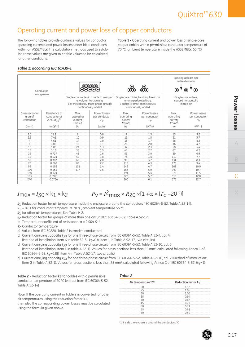
C.17
QuiXtra™630Pow
er losses
A
B
C
X
Table 2 – Reduction factor k1 for cables with a permissible conductor temperature of 70 °C (extract from IEC 60364-5-52, Table A.52-14)
Note: If the operating current in Table 2 is converted for other air temperatures using the reduction factor k1,then also the corresponding power losses must be calculated using the formula given above.
The following tables provide guidance values for conductor operating currents and power losses under ideal conditions within an ASSEMBLY. The calculation methods used to estab-lish these values are given to enable values to be calculated for other conditions.
Table 1 - Operating current and power loss of single-core copper cables with a permissible conductor temperature of 70 °C (ambient temperature inside the ASSEMBLY: 55 °C)
Table 2Air temperature °C(1) Reduction factor k1
20 1.1225 1.0630 1.0035 0.9440 0.8745 0.7950 0.7155 0.6160 0.50
(1) inside the enclosure around the conductors °C
Table 1: according IEC 61439-1
Conductorarrangement
Spacing at least onecable diameter
Single-core cables in a cable trunking on a wall, run horizontally.
6 of the cables (2 three-phase circuits) continuously loaded
Single-core cables, touching free in air or on a perforated tray.
6 cables (2 three-phase circuits) continuously loaded
Single-core cables,spaced horizontally
in free air
Crosssectionalarea of
conductor
(mm²)
Resistance of conductor at20°C, R20a)
(mΩ/m)
Max.operating
currentImaxb)
(A)
Power lossesper conductor
Pv
(W/m)
Max.operating
currentImaxc)
(A)
Power lossesper conductor
Pv
(W/m)
Max.operating
currentImaxd)
(A)
Power lossesper conductor
Pv
(W/m)
1.5 12.1 8 0.8 9 1.3 15 3.22.5 7.41 10 0.9 13 1.5 21 3.74 4.61 14 1.0 18 1.7 28 4.26 3.08 18 1.1 23 2.0 36 4.7
10 1.83 24 1.3 32 2.3 50 5.416 1.15 33 1.5 44 2.7 67 6.225 0.727 43 1.6 59 3.0 89 6.935 0.524 54 1.8 74 3.4 110 7.750 0.387 65 2.0 90 3.7 134 8.370 0.268 83 2.2 116 4.3 171 9.495 0.193 101 2.4 142 4.7 208 10.0
120 0.153 117 2.5 165 5.0 242 10.7150 0.124 191 5.4 278 11.5185 0.0991 220 5.7 318 12.0240 0.0754 260 6.1 375 12.7
Imax = I30 × k1 × k2 Pv = I2max × R20 ×[1 +α × (Tc −20 °)]
k1 Reduction factor for air temperature inside the enclosure around the conductors (IEC 60364-5-52, Table A.52-14).k1 = 0.61 for conductor temperature 70 °C, ambient temperature 55 °C.k1 for other air temperatures: See Table H.2.k2 Reduction factor for groups of more than one circuit (IEC 60364-5-52, Table A.52-17).α Temperature coeffi cient of resistance, α = 0.004 K-1
Tc Conductor temperaturea) Values from IEC 60228, Table 2 (stranded conductors)b) Current carrying capacity I30 for one three-phase circuit from IEC 60364-5-52, Table A.52-4, col. 4
(Method of installation: Item 6 in table 52-3). k2=0.8 (item 1 in Table A.52-17, two circuits)c) Current carrying capacity I30 for one three-phase circuit from IEC 60364-5-52, Table A.52-10, col. 5
(Method of installation: Item F in table A.52-1). Values for cross-sections less than 25 mm² calculated following Annex C of IEC 60364-5-52. k2=0.88 (item 4 in Table A.52-17, two circuits)
d) Current carrying capacity I30 for one three-phase circuit from IEC 60364-5-52, Table A.52-10, col. 7 (Method of installation: Item G in Table A.52-1). Values for cross-sections less than 25 mm² calculated following Annex C of IEC 60364-5-52. (k2=1)
Operating current and power loss of copper conductors
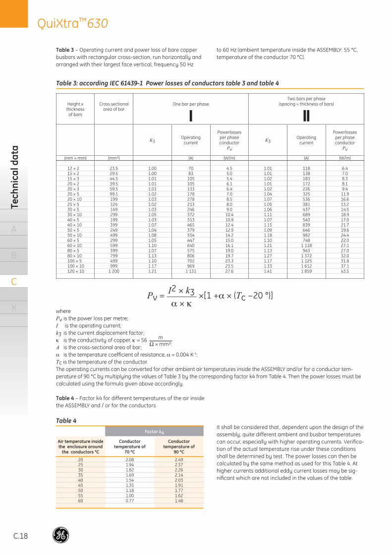
C.18
QuiXtra™630Te
chni
cal d
ata
A
B
C
X
Table 3: according IEC 61439-1 Power losses of conductors table 3 and table 4
Height xthickness
of bars
Cross sectionalarea of bar
One bar per phaseTwo bars per phase
(spacing = thickness of bars)
K3Operating
current
Powerlossesper phaseconductor
Pv
K3Operating
current
Powerlossesper phaseconductor
Pv
(mm × mm) (mm²) (A) (W/m) (A) (W/m)
12 × 2 23.5 1.00 70 4.5 1.01 118 6.415 × 2 29.5 1.00 83 5.0 1.01 138 7.015 × 3 44.5 1.01 105 5.4 1.02 183 8.320 × 2 39.5 1.01 105 6.1 1.01 172 8.120 × 3 59.5 1.01 133 6.4 1.02 226 9.420 × 5 99.1 1.02 178 7.0 1.04 325 11.920 × 10 199 1.03 278 8.5 1.07 536 16.625 × 5 124 1.02 213 8.0 1.05 381 13.230 × 5 149 1.03 246 9.0 1.06 437 14.530 × 10 299 1.05 372 10.4 1.11 689 18.940 × 5 199 1.03 313 10.9 1.07 543 17.040 × 10 399 1.07 465 12.4 1.15 839 21.750 × 5 249 1.04 379 12.9 1.09 646 19.650 × 10 499 1.08 554 14.2 1.18 982 24.460 × 5 299 1.05 447 15.0 1.10 748 22.060 × 10 599 1.10 640 16.1 1.21 1 118 27.180 × 5 399 1.07 575 19.0 1.13 943 27.080 × 10 799 1.13 806 19.7 1.27 1 372 32.0100 × 5 499 1.10 702 23.3 1.17 1 125 31.8100 × 10 999 1.17 969 23.5 1.33 1 612 37.1120 × 10 1 200 1.21 1 131 27.6 1.41 1 859 43.5
Pv = I2 × k3α × κ
×[1 +α × (Tc −20 °)]
wherePv is the power loss per metre;I is the operating current;k3 is the current displacement factor;κ is the conductivity of copper, κ = 56
m
Ω × mm²:A is the cross-sectional area of bar;α is the temperature coeffi cient of resistance, α = 0.004 K-1;Tc is the temperature of the conductor.The operating currents can be converted for other ambient air temperatures inside the ASSEMBLY and/or for a conductor tem-perature of 90 °C by multiplying the values of Table 3 by the corresponding factor k4 from Table 4. Then the power losses must be calculated using the formula given above accordingly.
Table 4 – Factor k4 for different temperatures of the air insidethe ASSEMBLY and / or for the conductors
Table 3 – Operating current and power loss of bare copper busbars with rectangular cross-section, run horizontally and arranged with their largest face vertical, frequency 50 Hz
to 60 Hz (ambient temperature inside the ASSEMBLY: 55 °C, temperature of the conductor 70 °C).
Table 4Factor k4
Air temperature inside the enclosure around
the conductors °C
Conductortemperature of
70 °C
Conductortemperature of
90 °C
20 2.08 2.4925 1.94 2.3730 1.82 2.2635 1.69 2.1440 1.54 2.0345 1.35 1.9150 1.18 1.7755 1.00 1.6260 0.77 1.48
It shall be considered that, dependent upon the design of the assembly, quite different ambient and busbar temperatures can occur, especially with higher operating currents. Verifi ca-tion of the actual temperature rise under these conditions shall be determined by test. The power losses can then be calculated by the same method as used for this Table 4. At higher currents additional eddy current losses may be sig-nifi cant which are not included in the values of the table.
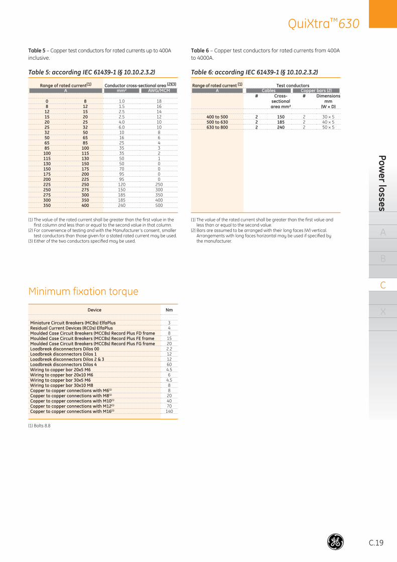
C.19
QuiXtra™630Pow
er losses
A
B
C
X
Table 5 – Copper test conductors for rated currents up to 400A inclusive.
Table 5: according IEC 61439-1 (§ 10.10.2.3.2)
Range of rated current(1) Conductor cross-sectional area (2)(3)A mm² AWG/MCM
0 8 1.0 188 12 1.5 16
12 15 2.5 1415 20 2.5 1220 25 4.0 1025 32 6.0 1032 50 10 850 65 16 665 85 25 485 100 35 3
100 115 35 2115 130 50 1130 150 50 0150 175 70 0175 200 95 0200 225 95 0225 250 120 250250 275 150 300275 300 185 350300 350 185 400350 400 240 500
(1) The value of the rated current shall be greater than the fi rst value in the fi rst column and less than or equal to the second value in that column.
(2) For convenience of testing and with the Manufacturer’s consent, smaller test conductors than those given for a stated rated current may be used.
(3) Either of the two conductors specifi ed may be used.
Table 6 – Copper test conductors for rated currents from 400A to 4000A.
Table 6: according IEC 61439-1 (§ 10.10.2.3.2)
Range of rated current (1) Test conductorsA Cables Copper bars (2)
# Cross-sectional area mm²
# Dimensions mm
(W × D)
400 to 500 2 150 2 30 × 5500 to 630 2 185 2 40 × 5630 to 800 2 240 2 50 × 5
(1) The value of the rated current shall be greater than the fi rst value and less than or equal to the second value.
(2) Bars are assumed to be arranged with their long faces (W) vertical. Arrangements with long faces horizontal may be used if specifi ed by the manufacturer.
Device Nm
Miniature Circuit Breakers (MCBs) ElfaPlus 3Residual Current Devices (RCDs) ElfaPlus 4Moulded Case Circuit Breakers (MCCBs) Record Plus FD frame 8Moulded Case Circuit Breakers (MCCBs) Record Plus FE frame 15Moulded Case Circuit Breakers (MCCBs) Record Plus FG frame 20Loadbreak disconnectors Dilos 00 2.2Loadbreak disconnectors Dilos 1 12Loadbreak disconnectors Dilos 2 & 3 12Loadbreak disconnectors Dilos 4 60Wiring to copper bar 20x5 M6 4.5Wiring to copper bar 20x10 M6 6Wiring to copper bar 30x5 M6 4.5Wiring to copper bar 30x10 M8 8Copper to copper connections with M6(1) 8Copper to copper connections with M8(1) 20Copper to copper connections with M10(1) 40Copper to copper connections with M12(1) 70Copper to copper connections with M16(1) 140
(1) Bolts 8.8
Minimum fixation torque
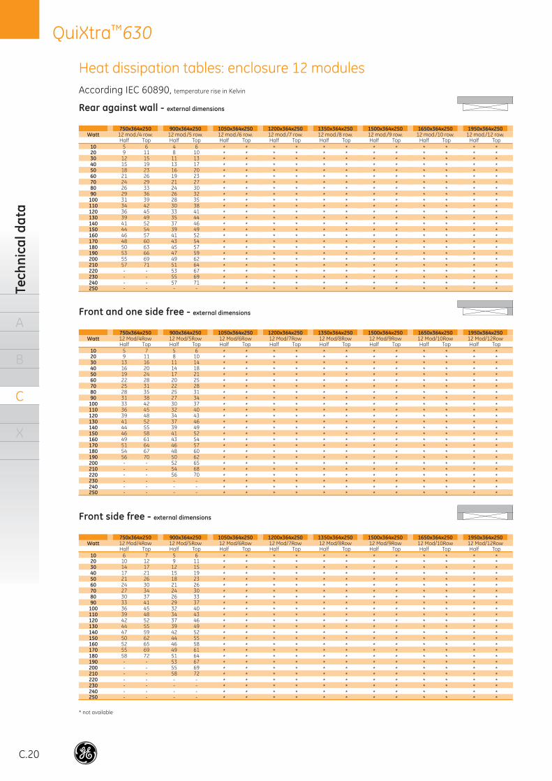
C.20
QuiXtra™630Te
chni
cal d
ata
A
B
C
X
Rear against wall - external dimensions
750x364x250 900x364x250 1050x364x250 1200x364x250 1350x364x250 1500x364x250 1650x364x250 1950x364x250Watt 12 mod./4 row. 12 mod./5 row. 12 mod./6 row. 12 mod./7 row. 12 mod./8 row. 12 mod./9 row. 12 mod./10 row. 12 mod./12 row.
Half Top Half Top Half Top Half Top Half Top Half Top Half Top Half Top10 5 6 4 6 * * * * * * * * * * * *20 9 11 8 10 * * * * * * * * * * * *30 12 15 11 13 * * * * * * * * * * * *40 15 19 13 17 * * * * * * * * * * * *50 18 23 16 20 * * * * * * * * * * * *60 21 26 19 23 * * * * * * * * * * * *70 24 29 21 27 * * * * * * * * * * * *80 26 33 24 30 * * * * * * * * * * * *90 29 36 26 32 * * * * * * * * * * * *
100 31 39 28 35 * * * * * * * * * * * *110 34 42 30 38 * * * * * * * * * * * *120 36 45 33 41 * * * * * * * * * * * *130 39 49 35 44 * * * * * * * * * * * *140 41 52 37 46 * * * * * * * * * * * *150 44 54 39 49 * * * * * * * * * * * *160 46 57 41 52 * * * * * * * * * * * *170 48 60 43 54 * * * * * * * * * * * *180 50 63 45 57 * * * * * * * * * * * *190 53 66 47 59 * * * * * * * * * * * *200 55 69 49 62 * * * * * * * * * * * *210 57 71 51 64 * * * * * * * * * * * *220 - - 53 67 * * * * * * * * * * * *230 - - 55 69 * * * * * * * * * * * *240 - - 57 71 * * * * * * * * * * * *250 - - - - * * * * * * * * * * * *
Front side free - external dimensions
750x364x250 900x364x250 1050x364x250 1200x364x250 1350x364x250 1500x364x250 1650x364x250 1950x364x250Watt 12 Mod/4Row 12 Mod/5Row 12 Mod/6Row 12 Mod/7Row 12 Mod/8Row 12 Mod/9Row 12 Mod/10Row 12 Mod/12Row
Half Top Half Top Half Top Half Top Half Top Half Top Half Top Half Top10 6 7 5 6 * * * * * * * * * * * *20 10 12 9 11 * * * * * * * * * * * *30 14 17 12 15 * * * * * * * * * * * *40 17 21 15 19 * * * * * * * * * * * *50 21 26 18 23 * * * * * * * * * * * *60 24 30 21 26 * * * * * * * * * * * *70 27 34 24 30 * * * * * * * * * * * *80 30 37 26 33 * * * * * * * * * * * *90 33 41 29 37 * * * * * * * * * * * *
100 36 45 32 40 * * * * * * * * * * * *110 39 48 34 43 * * * * * * * * * * * *120 42 52 37 46 * * * * * * * * * * * *130 44 55 39 49 * * * * * * * * * * * *140 47 59 42 52 * * * * * * * * * * * *150 50 62 44 55 * * * * * * * * * * * *160 52 65 46 58 * * * * * * * * * * * *170 55 69 49 61 * * * * * * * * * * * *180 58 72 51 64 * * * * * * * * * * * *190 - - 53 67 * * * * * * * * * * * *200 - - 55 69 * * * * * * * * * * * *210 - - 58 72 * * * * * * * * * * * *220 - - - - * * * * * * * * * * * *230 - - - - * * * * * * * * * * * *240 - - - - * * * * * * * * * * * *250 - - - - * * * * * * * * * * * *
Front and one side free - external dimensions
750x364x250 900x364x250 1050x364x250 1200x364x250 1350x364x250 1500x364x250 1650x364x250 1950x364x250Watt 12 Mod/4Row 12 Mod/5Row 12 Mod/6Row 12 Mod/7Row 12 Mod/8Row 12 Mod/9Row 12 Mod/10Row 12 Mod/12Row
Half Top Half Top Half Top Half Top Half Top Half Top Half Top Half Top10 5 7 5 6 * * * * * * * * * * * *20 9 11 8 10 * * * * * * * * * * * *30 13 16 11 14 * * * * * * * * * * * *40 16 20 14 18 * * * * * * * * * * * *50 19 24 17 21 * * * * * * * * * * * *60 22 28 20 25 * * * * * * * * * * * *70 25 31 22 28 * * * * * * * * * * * *80 28 35 25 31 * * * * * * * * * * * *90 31 38 27 34 * * * * * * * * * * * *
100 33 42 30 37 * * * * * * * * * * * *110 36 45 32 40 * * * * * * * * * * * *120 39 48 34 43 * * * * * * * * * * * *130 41 52 37 46 * * * * * * * * * * * *140 44 55 39 49 * * * * * * * * * * * *150 46 58 41 52 * * * * * * * * * * * *160 49 61 43 54 * * * * * * * * * * * *170 51 64 46 57 * * * * * * * * * * * *180 54 67 48 60 * * * * * * * * * * * *190 56 70 50 62 * * * * * * * * * * * *200 - - 52 65 * * * * * * * * * * * *210 - - 54 68 * * * * * * * * * * * *220 - - 56 70 * * * * * * * * * * * *230 - - - - * * * * * * * * * * * *240 - - - - * * * * * * * * * * * *250 - - - - * * * * * * * * * * * *
Heat dissipation tables: enclosure 12 modulesAccording IEC 60890, temperature rise in Kelvin
* not available
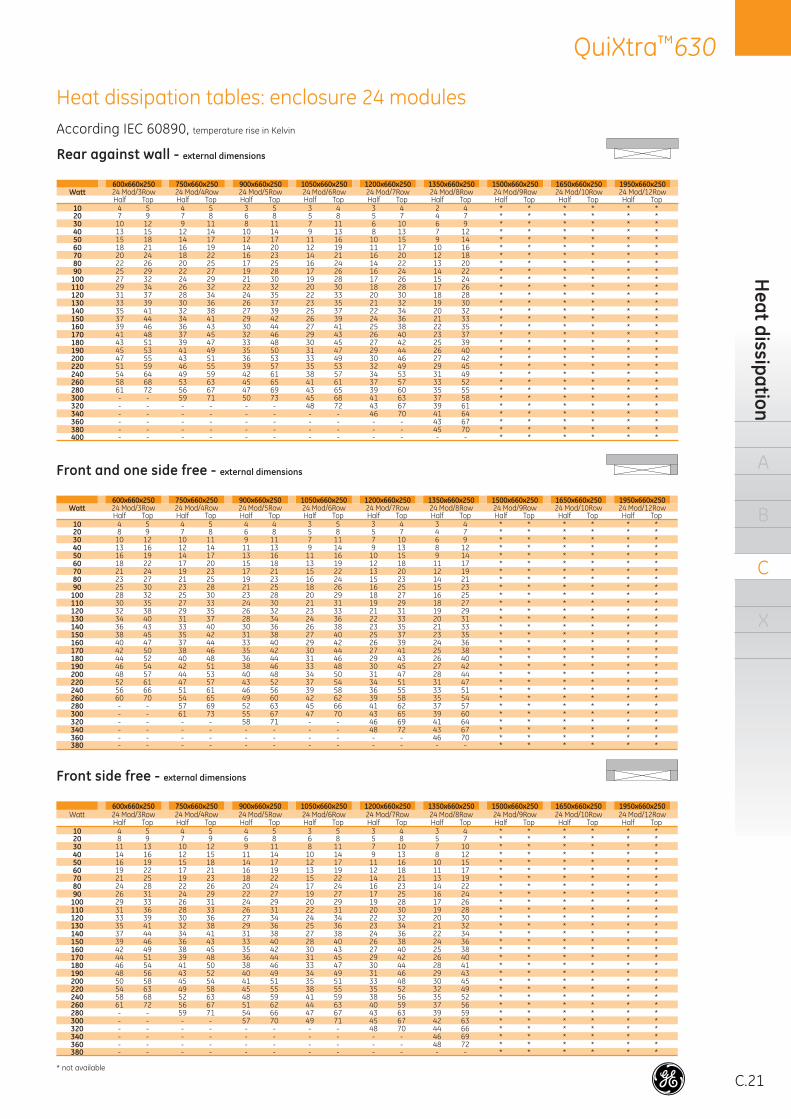
C.21
QuiXtra™630H
eat dissipation
A
B
C
X
According IEC 60890, temperature rise in Kelvin
Heat dissipation tables: enclosure 24 modules
Rear against wall - external dimensions
600x660x250 750x660x250 900x660x250 1050x660x250 1200x660x250 1350x660x250 1500x660x250 1650x660x250 1950x660x250Watt 24 Mod/3Row 24 Mod/4Row 24 Mod/5Row 24 Mod/6Row 24 Mod/7Row 24 Mod/8Row 24 Mod/9Row 24 Mod/10Row 24 Mod/12Row
Half Top Half Top Half Top Half Top Half Top Half Top Half Top Half Top Half Top10 4 5 4 5 3 5 3 4 3 4 2 4 * * * * * *20 7 9 7 8 6 8 5 8 5 7 4 7 * * * * * *30 10 12 9 11 8 11 7 11 6 10 6 9 * * * * * *40 13 15 12 14 10 14 9 13 8 13 7 12 * * * * * *50 15 18 14 17 12 17 11 16 10 15 9 14 * * * * * *60 18 21 16 19 14 20 12 19 11 17 10 16 * * * * * *70 20 24 18 22 16 23 14 21 16 20 12 18 * * * * * *80 22 26 20 25 17 25 16 24 14 22 13 20 * * * * * *90 25 29 22 27 19 28 17 26 16 24 14 22 * * * * * *
100 27 32 24 29 21 30 19 28 17 26 15 24 * * * * * *110 29 34 26 32 22 32 20 30 18 28 17 26 * * * * * *120 31 37 28 34 24 35 22 33 20 30 18 28 * * * * * *130 33 39 30 36 26 37 23 35 21 32 19 30 * * * * * *140 35 41 32 38 27 39 25 37 22 34 20 32 * * * * * *150 37 44 34 41 29 42 26 39 24 36 21 33 * * * * * *160 39 46 36 43 30 44 27 41 25 38 22 35 * * * * * *170 41 48 37 45 32 46 29 43 26 40 23 37 * * * * * *180 43 51 39 47 33 48 30 45 27 42 25 39 * * * * * *190 45 53 41 49 35 50 31 47 29 44 26 40 * * * * * *200 47 55 43 51 36 53 33 49 30 46 27 42 * * * * * *220 51 59 46 55 39 57 35 53 32 49 29 45 * * * * * *240 54 64 49 59 42 61 38 57 34 53 31 49 * * * * * *260 58 68 53 63 45 65 41 61 37 57 33 52 * * * * * *280 61 72 56 67 47 69 43 65 39 60 35 55 * * * * * *300 - - 59 71 50 73 45 68 41 63 37 58 * * * * * *320 - - - - - - 48 72 43 67 39 61 * * * * * *340 - - - - - - - - 46 70 41 64 * * * * * *360 - - - - - - - - - - 43 67 * * * * * *380 - - - - - - - - - - 45 70 * * * * * *400 - - - - - - - - - - - - * * * * * *
Front and one side free - external dimensions
600x660x250 750x660x250 900x660x250 1050x660x250 1200x660x250 1350x660x250 1500x660x250 1650x660x250 1950x660x250Watt 24 Mod/3Row 24 Mod/4Row 24 Mod/5Row 24 Mod/6Row 24 Mod/7Row 24 Mod/8Row 24 Mod/9Row 24 Mod/10Row 24 Mod/12Row
Half Top Half Top Half Top Half Top Half Top Half Top Half Top Half Top Half Top10 4 5 4 5 4 4 3 5 3 4 3 4 * * * * * *20 8 9 7 8 6 8 5 8 5 7 4 7 * * * * * *30 10 12 10 11 9 11 7 11 7 10 6 9 * * * * * *40 13 16 12 14 11 13 9 14 9 13 8 12 * * * * * *50 16 19 14 17 13 16 11 16 10 15 9 14 * * * * * *60 18 22 17 20 15 18 13 19 12 18 11 17 * * * * * *70 21 24 19 23 17 21 15 22 13 20 12 19 * * * * * *80 23 27 21 25 19 23 16 24 15 23 14 21 * * * * * *90 25 30 23 28 21 25 18 26 16 25 15 23 * * * * * *
100 28 32 25 30 23 28 20 29 18 27 16 25 * * * * * *110 30 35 27 33 24 30 21 31 19 29 18 27 * * * * * *120 32 38 29 35 26 32 23 33 21 31 19 29 * * * * * *130 34 40 31 37 28 34 24 36 22 33 20 31 * * * * * *140 36 43 33 40 30 36 26 38 23 35 21 33 * * * * * *150 38 45 35 42 31 38 27 40 25 37 23 35 * * * * * *160 40 47 37 44 33 40 29 42 26 39 24 36 * * * * * *170 42 50 38 46 35 42 30 44 27 41 25 38 * * * * * *180 44 52 40 48 36 44 31 46 29 43 26 40 * * * * * *190 46 54 42 51 38 46 33 48 30 45 27 42 * * * * * *200 48 57 44 53 40 48 34 50 31 47 28 44 * * * * * *220 52 61 47 57 43 52 37 54 34 51 31 47 * * * * * *240 56 66 51 61 46 56 39 58 36 55 33 51 * * * * * *260 60 70 54 65 49 60 42 62 39 58 35 54 * * * * * *280 - - 57 69 52 63 45 66 41 62 37 57 * * * * * *300 - - 61 73 55 67 47 70 43 65 39 60 * * * * * *320 - - - - 58 71 - - 46 69 41 64 * * * * * *340 - - - - - - - - 48 72 43 67 * * * * * *360 - - - - - - - - - - 46 70 * * * * * *380 - - - - - - - - - - - - * * * * * *
Front side free - external dimensions
600x660x250 750x660x250 900x660x250 1050x660x250 1200x660x250 1350x660x250 1500x660x250 1650x660x250 1950x660x250Watt 24 Mod/3Row 24 Mod/4Row 24 Mod/5Row 24 Mod/6Row 24 Mod/7Row 24 Mod/8Row 24 Mod/9Row 24 Mod/10Row 24 Mod/12Row
Half Top Half Top Half Top Half Top Half Top Half Top Half Top Half Top Half Top10 4 5 4 5 4 5 3 5 3 4 3 4 * * * * * *20 8 9 7 9 6 8 6 8 5 8 5 7 * * * * * *30 11 13 10 12 9 11 8 11 7 10 7 10 * * * * * *40 14 16 12 15 11 14 10 14 9 13 8 12 * * * * * *50 16 19 15 18 14 17 12 17 11 16 10 15 * * * * * *60 19 22 17 21 16 19 13 19 12 18 11 17 * * * * * *70 21 25 19 23 18 22 15 22 14 21 13 19 * * * * * *80 24 28 22 26 20 24 17 24 16 23 14 22 * * * * * *90 26 31 24 29 22 27 19 27 17 25 16 24 * * * * * *
100 29 33 26 31 24 29 20 29 19 28 17 26 * * * * * *110 31 36 28 33 26 31 22 31 20 30 19 28 * * * * * *120 33 39 30 36 27 34 24 34 22 32 20 30 * * * * * *130 35 41 32 38 29 36 25 36 23 34 21 32 * * * * * *140 37 44 34 41 31 38 27 38 24 36 22 34 * * * * * *150 39 46 36 43 33 40 28 40 26 38 24 36 * * * * * *160 42 49 38 45 35 42 30 43 27 40 25 38 * * * * * *170 44 51 39 48 36 44 31 45 29 42 26 40 * * * * * *180 46 54 41 50 38 46 33 47 30 44 28 41 * * * * * *190 48 56 43 52 40 49 34 49 31 46 29 43 * * * * * *200 50 58 45 54 41 51 35 51 33 48 30 45 * * * * * *220 54 63 49 58 45 55 38 55 35 52 32 49 * * * * * *240 58 68 52 63 48 59 41 59 38 56 35 52 * * * * * *260 61 72 56 67 51 62 44 63 40 59 37 56 * * * * * *280 - - 59 71 54 66 47 67 43 63 39 59 * * * * * *300 - - - - 57 70 49 71 45 67 42 63 * * * * * *320 - - - - - - - - 48 70 44 66 * * * * * *340 - - - - - - - - - - 46 69 * * * * * *360 - - - - - - - - - - 48 72 * * * * * *380 - - - - - - - - - - - - * * * * * *
* not available
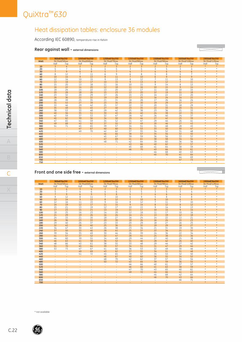
C.22
QuiXtra™630Te
chni
cal d
ata
A
B
C
X
Rear against wall - external dimensions
900x876x250 1050x876x250 1200x876x250 1350x876x250 1500x876x250 1650x876x250 1950x876x250Watt 36 Mod/5Row 36 Mod/6Row 36 Mod/7Row 36 Mod/8Row 36 Mod/9Row 36 Mod/10Row 36 Mod/12Row
Half Top Half Top Half Top Half Top Half Top Half Top Half Top10 3 4 2 3 2 3 2 3 2 3 2 2 * *20 5 7 4 6 4 5 3 5 3 5 3 4 * *30 7 9 6 8 5 7 4 7 4 6 4 6 * *40 8 12 7 11 6 9 6 8 5 8 5 7 * *50 10 14 9 13 8 11 7 10 6 9 6 9 * *60 12 16 10 15 9 13 8 12 7 11 6 10 * *70 13 18 12 17 10 15 9 13 8 12 7 11 * *80 15 20 13 18 11 16 10 15 9 14 8 13 * *90 16 22 14 20 12 18 11 16 10 15 9 14 * *
100 18 24 15 22 13 20 12 17 11 16 10 15 * *120 20 28 18 26 15 23 13 20 12 19 11 18 * *140 23 32 20 29 17 26 15 23 14 22 13 20 * *160 26 36 22 32 19 29 17 25 16 24 14 22 * *180 28 39 25 35 21 31 18 28 17 26 16 24 * *200 31 43 27 39 23 34 20 30 19 29 17 27 * *220 33 46 29 42 25 37 22 33 20 31 18 29 * *240 35 49 31 45 27 40 23 35 22 33 20 31 * *260 38 53 33 48 29 42 25 38 23 36 21 33 * *280 40 56 35 51 30 45 26 40 24 38 22 35 * *300 42 59 37 53 32 47 28 42 26 40 24 37 * *320 45 62 39 56 34 50 29 44 27 42 25 39 * *340 47 65 41 59 35 52 31 47 29 44 26 41 * *360 49 68 43 62 37 55 32 49 30 46 27 43 * *380 51 71 45 65 39 57 34 51 31 48 28 45 * *400 - - 47 67 40 60 35 53 33 50 30 47 * *420 - - 49 70 42 62 37 55 34 52 31 48 * *440 - - - - 44 64 38 57 35 54 32 50 * *460 - - - - 45 67 39 59 36 56 33 52 * *480 - - - - 47 69 41 61 38 58 34 54 * *500 - - - - 48 71 42 64 39 60 36 56 * *520 - - - - - - 43 66 40 62 37 57 * *540 - - - - - - 45 68 41 64 38 59 * *560 - - - - - - 46 70 43 66 39 61 * *580 - - - - - - - - 44 68 40 63 * *600 - - - - - - - - 45 70 41 64 * *650 - - - - - - - - - - 44 69 * *700 - - - - - - - - - - 47 73 * *750 - - - - - - - - - - - - * *
Front and one side free - external dimensions
900x876x250 1050x876x250 1200x876x250 1350x876x250 1500x876x250 1650x876x250 1950x876x250Watt 36 Mod/5Row 36 Mod/6Row 36 Mod/7Row 36 Mod/8Row 36 Mod/9Row 36 Mod/10Row 36 Mod/12Row
Half Top Half Top Half Top Half Top Half Top Half Top Half Top10 3 4 3 4 2 3 2 3 2 3 2 2 * *20 5 7 4 6 4 6 3 5 3 5 3 4 * *30 7 9 6 9 5 8 5 7 4 6 4 6 * *40 9 12 8 11 7 10 6 9 5 8 5 8 * *50 10 14 9 13 8 12 7 10 6 10 6 9 * *60 12 16 11 15 9 14 8 12 7 11 7 10 * *70 14 19 12 17 11 15 9 14 8 12 8 12 * *80 15 21 13 19 12 17 10 15 9 14 9 13 * *90 17 23 15 21 13 19 11 17 10 15 9 14 * *
100 18 25 16 23 14 20 12 18 11 17 10 16 * *120 21 29 19 26 16 24 14 21 13 19 12 18 * *140 24 33 21 30 18 27 16 24 14 22 13 21 * *160 26 36 23 33 20 30 18 26 16 24 15 23 * *180 29 40 26 37 23 33 20 29 18 27 16 25 * *200 32 43 28 40 25 36 21 32 19 29 18 27 * *220 34 47 30 43 26 38 23 34 21 31 19 30 * *240 37 50 33 46 28 41 25 37 22 34 21 32 * *260 39 54 35 49 30 44 26 39 24 36 22 34 * *280 41 57 37 52 32 47 28 41 25 38 23 36 * *300 44 60 39 55 34 49 29 44 27 40 25 38 * *320 46 63 41 58 36 52 31 46 28 42 26 40 * *340 48 66 43 61 38 55 33 48 29 44 27 42 * *360 51 70 45 64 39 57 34 51 31 47 29 44 * *380 53 73 47 67 41 60 36 53 32 49 30 46 * *400 - - 49 69 43 62 37 55 34 51 31 48 * *420 - - 51 72 45 65 39 57 35 53 32 50 * *440 - - - - 46 67 40 60 36 55 34 52 * *460 - - - - 48 70 42 62 37 57 35 54 * *480 - - - - 50 72 43 64 39 59 36 55 * *500 - - - - - - 44 66 40 61 37 57 * *520 - - - - - - 46 68 41 63 38 59 * *540 - - - - - - 47 70 43 65 40 61 * *560 - - - - - - 49 72 44 66 41 63 * *580 - - - - - - - - 45 68 42 64 * *600 - - - - - - - - 46 70 43 66 * *650 - - - - - - - - - - 46 71 * *700 - - - - - - - - - - - - * *
Heat dissipation tables: enclosure 36 modulesAccording IEC 60890, temperature rise in Kelvin
* not available
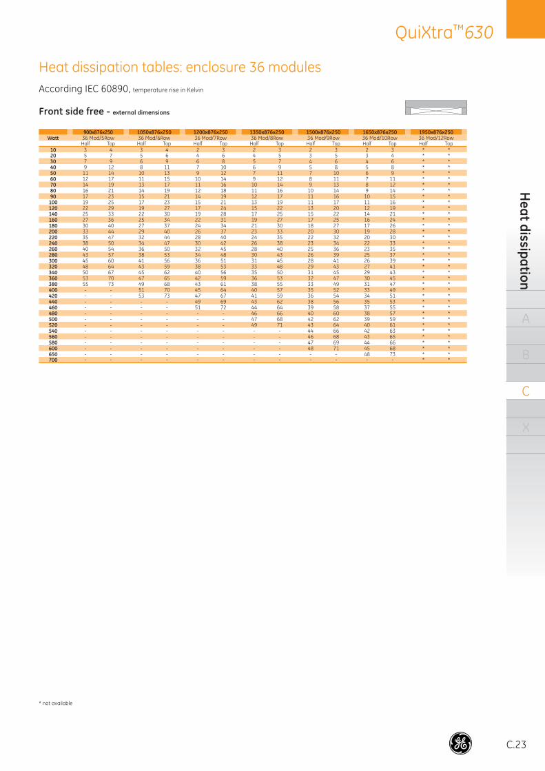
C.23
QuiXtra™630H
eat dissipation
A
B
C
X
Front side free - external dimensions
900x876x250 1050x876x250 1200x876x250 1350x876x250 1500x876x250 1650x876x250 1950x876x250Watt 36 Mod/5Row 36 Mod/6Row 36 Mod/7Row 36 Mod/8Row 36 Mod/9Row 36 Mod/10Row 36 Mod/12Row
Half Top Half Top Half Top Half Top Half Top Half Top Half Top10 3 4 3 4 2 3 2 3 2 3 2 3 * *20 5 7 5 6 4 6 4 5 3 5 3 4 * *30 7 9 6 9 6 8 5 7 4 6 4 6 * *40 9 12 8 11 7 10 6 9 5 8 5 8 * *50 11 14 10 13 9 12 7 11 7 10 6 9 * *60 12 17 11 15 10 14 9 12 8 11 7 11 * *70 14 19 13 17 11 16 10 14 9 13 8 12 * *80 16 21 14 19 12 18 11 16 10 14 9 14 * *90 17 23 15 21 14 19 12 17 11 16 10 15 * *
100 19 25 17 23 15 21 13 19 11 17 11 16 * *120 22 29 19 27 17 24 15 22 13 20 12 19 * *140 25 33 22 30 19 28 17 25 15 22 14 21 * *160 27 36 25 34 22 31 19 27 17 25 16 24 * *180 30 40 27 37 24 34 21 30 18 27 17 26 * *200 33 44 29 40 26 37 23 33 20 30 19 28 * *220 35 47 32 44 28 40 24 35 22 32 20 30 * *240 38 50 34 47 30 42 26 38 23 34 22 33 * *260 40 54 36 50 32 45 28 40 25 36 23 35 * *280 43 57 38 53 34 48 30 43 26 39 25 37 * *300 45 60 41 56 36 51 31 45 28 41 26 39 * *320 48 64 43 59 38 53 33 48 29 43 27 41 * *340 50 67 45 62 40 56 35 50 31 45 29 43 * *360 53 70 47 65 42 59 36 53 32 47 30 45 * *380 55 73 49 68 43 61 38 55 33 49 31 47 * *400 - - 51 70 45 64 40 57 35 52 33 49 * *420 - - 53 73 47 67 41 59 36 54 34 51 * *440 - - - - 49 69 43 62 38 56 35 53 * *460 - - - - 51 72 44 64 39 58 37 55 * *480 - - - - - - 46 66 40 60 38 57 * *500 - - - - - - 47 68 42 62 39 59 * *520 - - - - - - 49 71 43 64 40 61 * *540 - - - - - - - - 44 66 42 63 * *560 - - - - - - - - 46 68 43 65 * *580 - - - - - - - - 47 69 44 66 * *600 - - - - - - - - 48 71 45 68 * *650 - - - - - - - - - - 48 73 * *700 - - - - - - - - - - - - * *
Heat dissipation tables: enclosure 36 modulesAccording IEC 60890, temperature rise in Kelvin
* not available
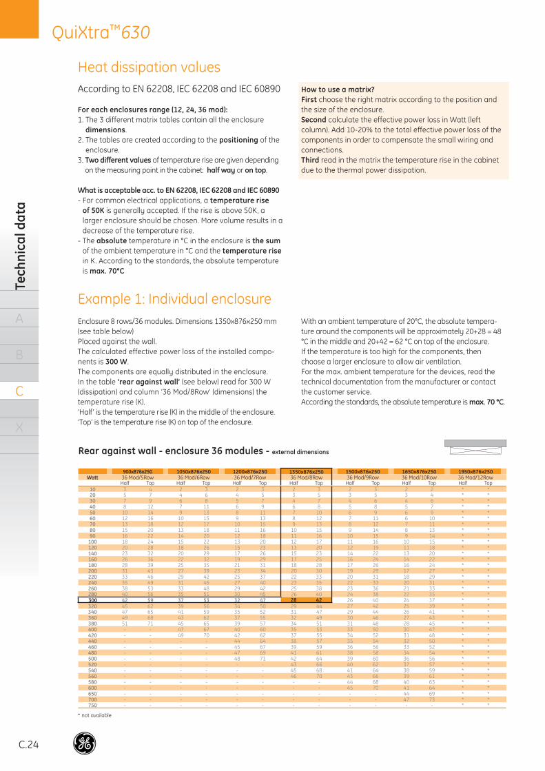
C.24
QuiXtra™630Te
chni
cal d
ata
A
B
C
X
According to EN 62208, IEC 62208 and IEC 60890
For each enclosures range (12, 24, 36 mod):1. The 3 different matrix tables contain all the enclosure
dimensions.2. The tables are created according to the positioning of the
enclosure.3. Two different values of temperature rise are given depending
on the measuring point in the cabinet: half way or on top.
What is acceptable acc. to EN 62208, IEC 62208 and IEC 60890- For common electrical applications, a temperature rise
of 50K is generally accepted. If the rise is above 50K, a larger enclosure should be chosen. More volume results in a decrease of the temperature rise.
- The absolute temperature in °C in the enclosure is the sum of the ambient temperature in °C and the temperature rise in K. According to the standards, the absolute temperature is max. 70°C
Enclosure 8 rows/36 modules. Dimensions 1350x876x250 mm(see table below)Placed against the wall.The calculated effective power loss of the installed compo-nents is 300 W.The components are equally distributed in the enclosure.In the table ‘rear against wall’ (see below) read for 300 W (dissipation) and column ’36 Mod/8Row’ (dimensions) the temperature rise (K).‘Half’ is the temperature rise (K) in the middle of the enclosure.‘Top’ is the temperature rise (K) on top of the enclosure.
With an ambient temperature of 20°C, the absolute tempera-ture around the components will be approximately 20+28 = 48 °C in the middle and 20+42 = 62 °C on top of the enclosure.If the temperature is too high for the components, then choose a larger enclosure to allow air ventilation.For the max. ambient temperature for the devices, read the technical documentation from the manufacturer or contact the customer service.According the standards, the absolute temperature is max. 70 °C.
Heat dissipation values
* not available
Example 1: Individual enclosure
Rear against wall - enclosure 36 modules - external dimensions
900x876x250 1050x876x250 1200x876x250 1350x876x250 1500x876x250 1650x876x250 1950x876x250Watt 36 Mod/5Row 36 Mod/6Row 36 Mod/7Row 36 Mod/8Row 36 Mod/9Row 36 Mod/10Row 36 Mod/12Row
Half Top Half Top Half Top Half Top Half Top Half Top Half Top10 3 4 2 3 2 3 2 3 2 3 2 2 * *20 5 7 4 6 4 5 3 5 3 5 3 4 * *30 7 9 6 8 5 7 4 7 4 6 4 6 * *40 8 12 7 11 6 9 6 8 5 8 5 7 * *50 10 14 9 13 8 11 7 10 6 9 6 9 * *60 12 16 10 15 9 13 8 12 7 11 6 10 * *70 13 18 12 17 10 15 9 13 8 12 7 11 * *80 15 20 13 18 11 16 10 15 9 14 8 13 * *90 16 22 14 20 12 18 11 16 10 15 9 14 * *
100 18 24 15 22 13 20 12 17 11 16 10 15 * *120 20 28 18 26 15 23 13 20 12 19 11 18 * *140 23 32 20 29 17 26 15 23 14 22 13 20 * *160 26 36 22 32 19 29 17 25 16 24 14 22 * *180 28 39 25 35 21 31 18 28 17 26 16 24 * *200 31 43 27 39 23 34 20 30 19 29 17 27 * *220 33 46 29 42 25 37 22 33 20 31 18 29 * *240 35 49 31 45 27 40 23 35 22 33 20 31 * *260 38 53 33 48 29 42 25 38 23 36 21 33 * *280 40 56 35 51 30 45 26 40 24 38 22 35 * *300 42 59 37 53 32 47 28 42 26 40 24 37 * *320 45 62 39 56 34 50 29 44 27 42 25 39 * *340 47 65 41 59 35 52 31 47 29 44 26 41 * *360 49 68 43 62 37 55 32 49 30 46 27 43 * *380 51 71 45 65 39 57 34 51 31 48 28 45 * *400 - - 47 67 40 60 35 53 33 50 30 47 * *420 - - 49 70 42 62 37 55 34 52 31 48 * *440 - - - - 44 64 38 57 35 54 32 50 * *460 - - - - 45 67 39 59 36 56 33 52 * *480 - - - - 47 69 41 61 38 58 34 54 * *500 - - - - 48 71 42 64 39 60 36 56 * *520 - - - - - - 43 66 40 62 37 57 * *540 - - - - - - 45 68 41 64 38 59 * *560 - - - - - - 46 70 43 66 39 61 * *580 - - - - - - - - 44 68 40 63 * *600 - - - - - - - - 45 70 41 64 * *650 - - - - - - - - - - 44 69 * *700 - - - - - - - - - - 47 73 * *750 - - - - - - - - - - - - * *
How to use a matrix?First choose the right matrix according to the position and the size of the enclosure.Second calculate the effective power loss in Watt (left column). Add 10-20% to the total effective power loss of the components in order to compensate the small wiring and connections.Third read in the matrix the temperature rise in the cabinetdue to the thermal power dissipation.
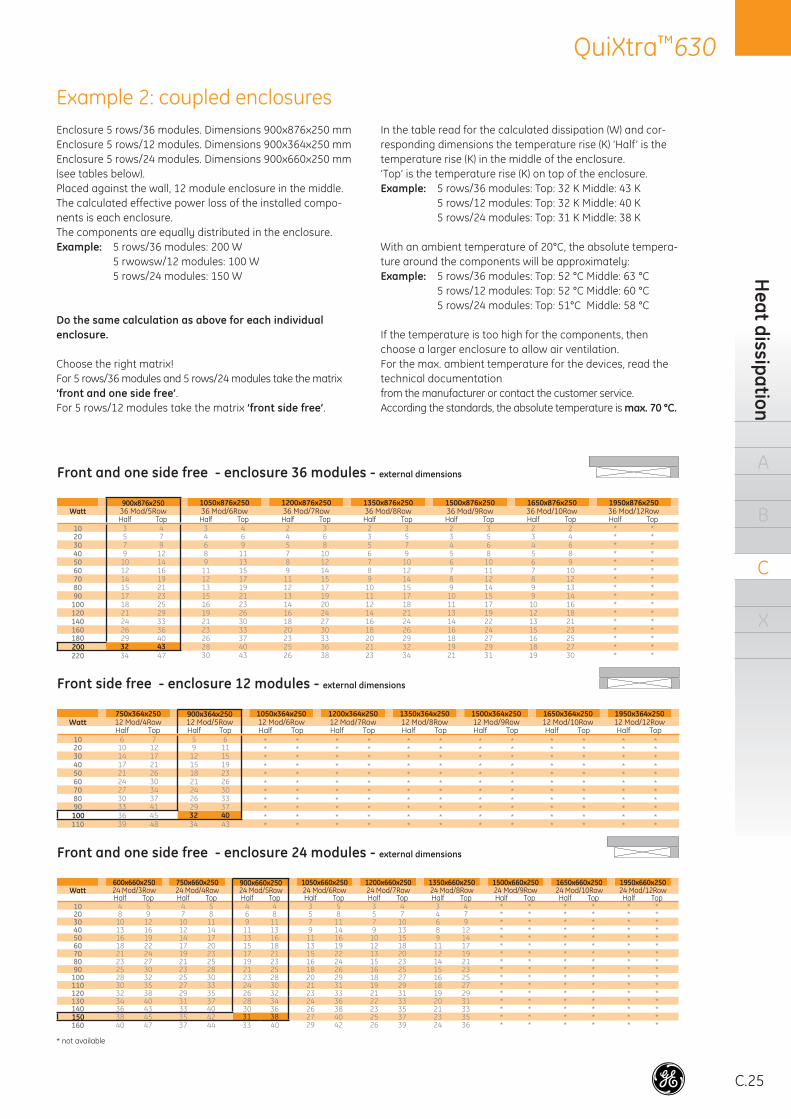
C.25
QuiXtra™630H
eat dissipation
A
B
C
X
Example 2: coupled enclosuresEnclosure 5 rows/36 modules. Dimensions 900x876x250 mm Enclosure 5 rows/12 modules. Dimensions 900x364x250 mm Enclosure 5 rows/24 modules. Dimensions 900x660x250 mm (see tables below).Placed against the wall, 12 module enclosure in the middle.The calculated effective power loss of the installed compo-nents is each enclosure.The components are equally distributed in the enclosure.Example: 5 rows/36 modules: 200 W 5 rwowsw/12 modules: 100 W 5 rows/24 modules: 150 W
Do the same calculation as above for each individual enclosure.
Choose the right matrix!For 5 rows/36 modules and 5 rows/24 modules take the matrix‘front and one side free’. For 5 rows/12 modules take the matrix ‘front side free’.
In the table read for the calculated dissipation (W) and cor-responding dimensions the temperature rise (K) ‘Half’ is the temperature rise (K) in the middle of the enclosure.‘Top’ is the temperature rise (K) on top of the enclosure.Example: 5 rows/36 modules: Top: 32 K Middle: 43 K 5 rows/12 modules: Top: 32 K Middle: 40 K 5 rows/24 modules: Top: 31 K Middle: 38 K
With an ambient temperature of 20°C, the absolute tempera-ture around the components will be approximately:Example: 5 rows/36 modules: Top: 52 °C Middle: 63 °C 5 rows/12 modules: Top: 52 °C Middle: 60 °C 5 rows/24 modules: Top: 51°C Middle: 58 °C
If the temperature is too high for the components, then choose a larger enclosure to allow air ventilation.For the max. ambient temperature for the devices, read the technical documentationfrom the manufacturer or contact the customer service.According the standards, the absolute temperature is max. 70 °C.
* not available
Front and one side free - enclosure 36 modules - external dimensions
900x876x250 1050x876x250 1200x876x250 1350x876x250 1500x876x250 1650x876x250 1950x876x250Watt 36 Mod/5Row 36 Mod/6Row 36 Mod/7Row 36 Mod/8Row 36 Mod/9Row 36 Mod/10Row 36 Mod/12Row
Half Top Half Top Half Top Half Top Half Top Half Top Half Top10 3 4 3 4 2 3 2 3 2 3 2 2 * *20 5 7 4 6 4 6 3 5 3 5 3 4 * *30 7 9 6 9 5 8 5 7 4 6 4 6 * *40 9 12 8 11 7 10 6 9 5 8 5 8 * *50 10 14 9 13 8 12 7 10 6 10 6 9 * *60 12 16 11 15 9 14 8 12 7 11 7 10 * *70 14 19 12 17 11 15 9 14 8 12 8 12 * *80 15 21 13 19 12 17 10 15 9 14 9 13 * *90 17 23 15 21 13 19 11 17 10 15 9 14 * *
100 18 25 16 23 14 20 12 18 11 17 10 16 * *120 21 29 19 26 16 24 14 21 13 19 12 18 * *140 24 33 21 30 18 27 16 24 14 22 13 21 * *160 26 36 23 33 20 30 18 26 16 24 15 23 * *180 29 40 26 37 23 33 20 29 18 27 16 25 * *200 32 43 28 40 25 36 21 32 19 29 18 27 * *220 34 47 30 43 26 38 23 34 21 31 19 30 * *
Front side free - enclosure 12 modules - external dimensions
750x364x250 900x364x250 1050x364x250 1200x364x250 1350x364x250 1500x364x250 1650x364x250 1950x364x250Watt 12 Mod/4Row 12 Mod/5Row 12 Mod/6Row 12 Mod/7Row 12 Mod/8Row 12 Mod/9Row 12 Mod/10Row 12 Mod/12Row
Half Top Half Top Half Top Half Top Half Top Half Top Half Top Half Top10 6 7 5 6 * * * * * * * * * * * *20 10 12 9 11 * * * * * * * * * * * *30 14 17 12 15 * * * * * * * * * * * *40 17 21 15 19 * * * * * * * * * * * *50 21 26 18 23 * * * * * * * * * * * *60 24 30 21 26 * * * * * * * * * * * *70 27 34 24 30 * * * * * * * * * * * *80 30 37 26 33 * * * * * * * * * * * *90 33 41 29 37 * * * * * * * * * * * *100 36 45 32 40 * * * * * * * * * * * *110 39 48 34 43 * * * * * * * * * * * *
Front and one side free - enclosure 24 modules - external dimensions
600x660x250 750x660x250 900x660x250 1050x660x250 1200x660x250 1350x660x250 1500x660x250 1650x660x250 1950x660x250Watt 24 Mod/3Row 24 Mod/4Row 24 Mod/5Row 24 Mod/6Row 24 Mod/7Row 24 Mod/8Row 24 Mod/9Row 24 Mod/10Row 24 Mod/12Row
Half Top Half Top Half Top Half Top Half Top Half Top Half Top Half Top Half Top10 4 5 4 5 4 4 3 5 3 4 3 4 * * * * * *20 8 9 7 8 6 8 5 8 5 7 4 7 * * * * * *30 10 12 10 11 9 11 7 11 7 10 6 9 * * * * * *40 13 16 12 14 11 13 9 14 9 13 8 12 * * * * * *50 16 19 14 17 13 16 11 16 10 15 9 14 * * * * * *60 18 22 17 20 15 18 13 19 12 18 11 17 * * * * * *70 21 24 19 23 17 21 15 22 13 20 12 19 * * * * * *80 23 27 21 25 19 23 16 24 15 23 14 21 * * * * * *90 25 30 23 28 21 25 18 26 16 25 15 23 * * * * * *
100 28 32 25 30 23 28 20 29 18 27 16 25 * * * * * *110 30 35 27 33 24 30 21 31 19 29 18 27 * * * * * *120 32 38 29 35 26 32 23 33 21 31 19 29 * * * * * *130 34 40 31 37 28 34 24 36 22 33 20 31 * * * * * *140 36 43 33 40 30 36 26 38 23 35 21 33 * * * * * *150 38 45 35 42 31 38 27 40 25 37 23 35 * * * * * *160 40 47 37 44 33 40 29 42 26 39 24 36 * * * * * *
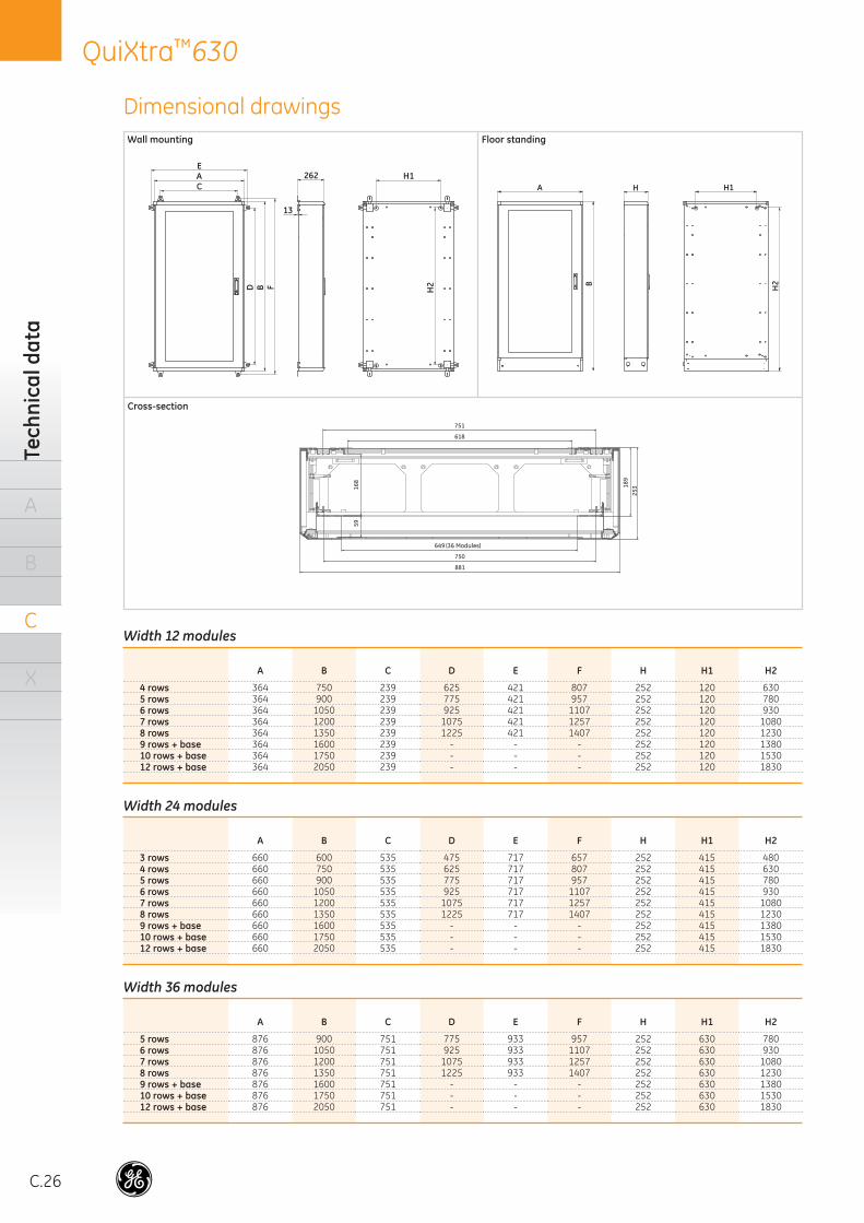
C.26
QuiXtra™630Te
chni
cal d
ata
A
B
C
X
Width 12 modules
A B C D E F H H1 H2
4 rows 364 750 239 625 421 807 252 120 6305 rows 364 900 239 775 421 957 252 120 7806 rows 364 1050 239 925 421 1107 252 120 9307 rows 364 1200 239 1075 421 1257 252 120 10808 rows 364 1350 239 1225 421 1407 252 120 12309 rows + base 364 1600 239 - - - 252 120 138010 rows + base 364 1750 239 - - - 252 120 153012 rows + base 364 2050 239 - - - 252 120 1830
Width 24 modules
A B C D E F H H1 H2
3 rows 660 600 535 475 717 657 252 415 4804 rows 660 750 535 625 717 807 252 415 6305 rows 660 900 535 775 717 957 252 415 7806 rows 660 1050 535 925 717 1107 252 415 9307 rows 660 1200 535 1075 717 1257 252 415 10808 rows 660 1350 535 1225 717 1407 252 415 12309 rows + base 660 1600 535 - - - 252 415 138010 rows + base 660 1750 535 - - - 252 415 153012 rows + base 660 2050 535 - - - 252 415 1830
Width 36 modules
A B C D E F H H1 H2
5 rows 876 900 751 775 933 957 252 630 7806 rows 876 1050 751 925 933 1107 252 630 9307 rows 876 1200 751 1075 933 1257 252 630 10808 rows 876 1350 751 1225 933 1407 252 630 12309 rows + base 876 1600 751 - - - 252 630 138010 rows + base 876 1750 751 - - - 252 630 153012 rows + base 876 2050 751 - - - 252 630 1830
Dimensional drawings
B
A H
H2
H1
B
AC
D
H1
H2
E
F
262
13
881
25316
859
750
(36 Modules)649
189
751
618
Wall mounting
Cross-section
Floor standing
C.27
QuiXtra™630Specifi cations
A
B
C
X
System Enclosure for Low Voltage distribution boards up to 630A
Conformity to standardsThe panels are designed according to the IEC 61439-2 stan-dard. All verifi cation tests and individual tests required by the standard have been done.Internal separation is Form 1. Form 2 can be achieved, as option.
Technical characteristicsThe panel is designed of kit-form enclosures made from sheet steel, which can be stand alone or coupled next to each other, for indoor use.
Each enclosure consists of in a high-strength rear plate, made of galvanized sheet steel 1.5 mm thick, with four aluminum corner parts bolted in each corner. The external panels and the doors are made in epoxy polyester power coating sheetsteel 1.25mm thick. All the external panels (top, bottom and side panels) are fi xed, using screws, to the aluminium corner parts. Each one can be disassembledindependently from the rest of the external panels.
The sheet steel parts are pre-treated with iron phosphate and protected with epoxy polyester powdercoating RAL 9006, giving a smooth fi nish. The colour for the external corner parts, the handle and the base is RAL 7024.
The range of QuiXtra 630 consists of 24 different sizes:• Three external widths: 364, 660 and 876 mm• Nine heights: external dimensions from 600 up to 2050mm.• One depth: 220mm without door and 250mm with the door• Useful dimensions:- Widths for 12, 24 and 36 modules 18mm- Heights from 450 up to 1800mm
The DIN rails or mounting plates of the functional units, and the busbar holders are fi xed with special “click-in” support, attaching to the vertical profi les which are fi xed to the rear panel. QuiXtra 630 allows free accessibility from all sides for the wiring of electrical devices mounted on the DIN rails and mounting plates, fi xed to the rear panel on the functional kits.
The functional units, based on a modular concept with a height in steps of 50 mm are available for:• Modular devices, for 12, 24 and 36 modules of 18mm.
In two different heights, 150 and 200 mm. One special function for screwless MCBs is available.
• Meters• Push-buttons• Moulded case circuit breakers. Up to 630A. To mount in
horizontal or in vertical position• Load break switches. Up to 630A. To mount in horizontal or
in vertical position.• Terminals• Plain mounting plates
Two busbar systems can be mounted in the enclosure:• Staircase busbar. Developed for easy accessibility during
wiring, to the four phases, because the holder shape puts the copper bars at different depths. The staircase busbar can be assembled in vertical position in the 12 module wide enclosure, and in horizontal position in the 24 and 36 module wide enclosure. Electrical devices cannot be mounted in front of a staircase busbar. The busbar holders are fi xed to the rear panel using specifi c “click in” supports and profi les.
• Rear mounted busbar. It Allows the assembly of the copper bars between the rear panel and the electrical devices. The rear busbar can be mounted in vertical or in horizontal position in all types of enclosure. The electrical devices can be mounted in front of the rear busbar in the enclosures 24 and 36 modules wide, except RecordPlus FG and Dilos 3&4. A busbar can span multiple coupled enclosures. The busbar holders are fi xed to the back plate using specifi c “click in” supports and profi les
• Vertical and horizontal separation screens allow the up-grade of the internal segregation form to Form 2, according the IEC 61439-2
The enclosures can be closed with two types of doors, plain and transparent. The plain door is available for the three enclosure widths and the transparent door is available for the 24 and 36 modules wide enclosures. The locking system is operated by a central handle and consists of a one or a three point locking mechanism, depending on the height of the enclosure. The doors are equipped with a lock insert for a 2432E key. The door can be assembled and disassembled without any tools, and can be opened from the right or the left side of the enclosure. The opening angle is 135º.
The enclosure offers maximum protection to the users and equipment thanks to an IP 43 protection degree with door and IP43 profi le, following IEC 60529 and the IEC 62262,
The enclosure has the KEMA approval.
Electrical characteristicsRated operational voltage: 415VRated insulation voltage: 690VRated short-circuit current: 30kA /1sRated busbar current system: up to 630AProtection degree: IP43 with door and IP43 profi le, IP40 with door and without IP43 profi le, IP30 without doorThe panel is designed for indoor use onlyAmbient temperature: 35°C
Specifications for tender documents
C.28
QuiXtra™630Te
chni
cal d
ata
A
B
C
X
IEC 60439 vs IEC 61439 for Assemblies up to 630A
The QuiXtra is designed according the recently published norm IEC 61439-1 and IEC 61439-2, pertaining to this type of system enclosure, in mind.
The new IEC 61439-2 supersedes the IEC 60439-1 norm. IEC 60439 was the norm that introduced the world to “type tested” and “partially type tested” assemblies. Because this terminology in the norm was open to gray zones and subjective interpretations, and therefore safety risks, they cease to exist in the new norm. The new standard IEC 61439 introduce the “Design verifi cation” approach. The Design verifi cation is achieved by testing, calculation or measurement and satisfying the design rules defi ned by the original manufacturer (OEM).The structure of the new IEC 61439 evolves from the IEC 60439. The structure for the new standard is:- IEC 61439-1. General rules- IEC 61439-2. Power Switchgear and Controlgear assemblies
(PSC-Assemblies)
IEC 61439-1 introduces a few new terms.
- Original Manufacturer (OEM): company producing enclosures & electrical switchgear: Here: GE
- Assembly Manufacturer: company assembling enclosures & equipping them with electrical switchgear. Responsible of the complete Assembly. Here: Panel Builder
- Verifi cation test: test performed by the original manufacturer to ensure that its enclosures and electrical switchgear are compliant with the norms.
In order for an assembly to comply to the new IEC 61439-2 norm, the original manufacturer needs to have conducted and passed verifi cation tests for its enclosures & components. For those enclosures and components, the OEM needs to provide documentation (typically in the form of Tables),enabling calculation of the critical parameters (heat dissipation, cable cross-sections) of an assembly, as well as clear instructions for its assembly and use.
The Assembly Manufacturer then makes this calculation for each assembly, and builds the assembly, strictly adhering to the instructions of the OEM.
If an assembly manufacturer uses a component not tested by the OEM of the enclosure, or if he makes modifi cations to the assembly not following the OEMs use instructions, it becomes his responsibility to ensure compliance with IEC 61439-2. That compliance must then be tested via a comprehensive test, to be performed by the assembly manufacturer.
GE has taken care to design the QuiXtra, together with original Record Plus, Dilos, Fulos and Redline/ElfaPlus equipment, to be fully compliant to IEC 61439-2. When building an assembly with GE components, and using the tables and calculation methods provided by GE, the assembly manufacturer can rest assured that his end product is fully IEC 61439-2 compliant.
Appendix
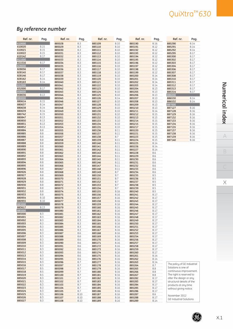
QuiXtra™630
X.1
Num
erical index
A
B
C
X
Ref. nr. Pag.885290 B.14885291 B.14885292 B.14885295 B.17885300 B.17885302 B.17885303 B.17885304 B.17885306 B.17885307 B.17885308 B.17885310 B.17885311 B.17885312 B.17885313 B.17885314 B.17886000886530 B.14886532 B.14887000887127 B.16887128 B.16887129 B.16887132 B.16887133 B.16887134 B.16887135 B.16887137 B.16887138 B.16887139 B.16887140 B.16
Ref. nr. Pag.610000610020 B.15610021 B.15610022 B.15610142 B.17811000811516 B.17828000828056 B.17828145 B.17828146 B.17828162 B.14828163 B.14832000832000 B.17858000858036 B.13880000880614 B.15880637 B.14880638 B.14880639 B.14880742 B.15880847 B.13880850 B.13880851 B.13880852 B.13880884 B.8880885 B.8880886 B.8880887 B.8880888 B.8880889 B.8880890 B.8880891 B.8880892 B.8880893 B.8880894 B.8880895 B.8880896 B.8880926 B.8880927 B.8880928 B.8880929 B.8880930 B.8880931 B.8880932 B.8880933 B.8880954 B.10880955 B.10883000883617 B.13885000885000 B.3885001 B.3885002 B.3885003 B.3885004 B.3885005 B.3885006 B.3885007 B.3885008 B.3885009 B.3885010 B.3885011 B.3885012 B.3885013 B.3885014 B.3885015 B.3885016 B.3885017 B.5885018 B.5885019 B.5885020 B.3885021 B.3885022 B.3885023 B.3885024 B.3885025 B.3885026 B.3885027 B.3
Ref. nr. Pag.885028 B.3885029 B.3885030 B.3885031 B.3885032 B.3885033 B.3885034 B.3885035 B.3885036 B.3885037 B.3885038 B.3885039 B.3885040 B.3885041 B.3885042 B.3885043 B.3885044 B.3885045 B.3885046 B.3885047 B.3885048 B.3885049 B.3885050 B.3885051 B.3885052 B.3885053 B.3885054 B.3885055 B.3885056 B.3885057 B.3885058 B.3885059 B.3885060 B.3885061 B.3885062 B.3885063 B.3885064 B.3885065 B.3885066 B.3885067 B.3885068 B.3885069 B.3885070 B.3885071 B.3885072 B.3885073 B.3885074 B.3885075 B.3885076 B.3885077 B.3885078 B.3885079 B.3885080 B.3885081 B.3885082 B.3885083 B.3885084 B.3885085 B.3885086 B.3885087 B.6885088 B.6885089 B.6885090 B.6885091 B.6885092 B.6885093 B.6885094 B.6885095 B.6885096 B.7885097 B.7885098 B.7885099 B.7885100 B.7885101 B.7885102 B.7885103 B.7885104 B.7885105 B.7885106 B.10885107 B.10885108 B.10
Ref. nr. Pag.885109 B.10885110 B.10885111 B.10885112 B.10885113 B.10885114 B.10885115 B.10885116 B.10885117 B.10885118 B.10885119 B.10885120 B.10885121 B.10885122 B.10885123 B.10885124 B.10885125 B.10885126 B.14885127 B.10885128 B.10885129 B.10885130 B.10885131 B.10885132 B.10885133 B.10885134 B.10885135 B.10885136 B.11885137 B.11885138 B.7885139 B.11885140 B.11885141 B.11885142 B.11885143 B.11885144 B.11885145 B.11885146 B.11885147 B.11885148 B.11885149 B.7885150 B.7885151 B.7885152 B.7885153 B.7885154 B.7885155 B.16885156 B.16885157 B.16885158 B.16885159 B.16885160 B.16885161 B.16885162 B.16885163 B.16885164 B.16885165 B.16885166 B.16885167 B.16885168 B.16885169 B.16885170 B.16885171 B.16885172 B.16885173 B.16885174 B.16885175 B.16885176 B.16885177 B.16885178 B.16885179 B.16885180 B.16885181 B.16885182 B.16885183 B.16885184 B.16885185 B.16885186 B.16885187 B.16885188 B.16885189 B.16
Ref. nr. Pag.885190 B.16885191 B.12885192 B.12885193 B.12885194 B.12885195 B.12885196 B.12885197 B.12885198 B.12885199 B.12885200 B.14885201 B.14885202 B.14885203 B.14885204 B.13885205 B.13885206 B.13885207 B.13885208 B.13885209 B.13885210 B.13885211 B.14885212 B.15885213 B.15885214 B.15885215 B.15885217 B.15885220 B.15885221 B.15885223 B.15885224 B.15885225 B.14885226 B.14885227 B.14885228 B.6885229 B.6885230 B.6885231 B.6885232 B.6885233 B.6885234 B.6885235 B.5885236 B.5885237 B.5885238 B.5885239 B.5885240 B.5885241 B.17885242 B.17885243 B.17885244 B.17885245 B.17885246 B.17885247 B.17885248 B.17885249 B.17885250 B.17885251 B.17885252 B.17885253 B.17885254 B.17885256 B.17885257 B.17885258 B.17885259 B.17885260 B.17885261 B.14885262 B.14885263 B.14885264 B.7885265 B.8885266 B.8885267 B.8885282 B.17885283 B.17885284 B.17885285 B.17885286 B.17885287 B.6885288 B.17885289 B.14
By reference number
The policy of GE Industrial Solutions is one of continuous improvement.The right is reserved to alter the design or any structural details of the products at any time without giving notice.
November 2012GE Industrial Solutions

1071
65
GE imagination at work
GEIndustrial Solutions
BelgiumGE Industrial BelgiumNieuwevaart 51B-9000 GentTel. +32 (0)9 265 21 11
FinlandGE Industrial SolutionsKuortaneenkatu 2FI-00510 HelsinkiTel. +358 (0)10 394 3760
FranceGE Industrial SolutionsParis Nord 213, rue de la PerdrixF-95958 Roissy CDG CédexTel. +33 (0)800 912 816
GermanyGE Industrial SolutionsRobert-Bosch Str. 2aD-50354 Hürth-EfferenTel. +49 (0) 2233/ 9719-0
HungaryGE Hungary Kft .Vaci ut 81-83.H-1139 BudapestTel. +36 1 447 6050
RussiaGE Industrial Solutions27/8, Electrozavodskaya streetMoscow, 107023Tel. +7 495 937 11 11
South AfricaGE Industrial SolutionsUnit 4, 130 Gazelle AvenueCorporate Park Midrand 1685P.O. Box 76672 Wendywood 2144 Tel. +27 11 238 3000
SpainGE Industrial SolutionsP.I. Clot del Tufau, s/nE-08295 Sant Vicenç de CastelletTel. +34 900 993 625
United Arab EmiratesGE Industrial SolutionsInjaz Building, 3rd FloorDubai Internet CityPO Box 11549, DubaiTel. +971 4 4546912
United KingdomGE Industrial SolutionsHoughton CentreSalthouse RoadBlackmillsNorthamptonNN4 7EXTel. +44 (0)800 587 1239
ItalyGE Industrial SolutionsCentro Direzionale ColleoniVia Paracelso 16Palazzo Andromeda B1I-20864 Agrate Brianza (MB)Tel. +39 039 637 3701
NetherlandsGE Industrial SolutionsParallelweg 10Nl-7482 CA HaaksbergenTel. +31 (0)53 573 03 03
PolandGE Power ControlsUl. Odrowaza 1503-310 WarszawaTel. +48 22 519 76 00
Ul. Leszczyńska 643-300 Bielsko-Biała Tel. +48 33 828 62 33
PortugalGE Industrial SolutionsRua Camilo Castelo Branco, 805Apartado 2770P-4401-601 Vila Nova de GaiaTel. +351 22 374 60 00
GE Industrial Solutions is a fi rst class global supplier of low and medium voltage products including wiring devices, residential and industrial electrical distribution components, automation products, enclosures and switchboards. Demand for the company’s products comes from wholesalers, installers, panelboard builders, contractors,OEMs and utilities worldwide.
www.ge.com/ex/industrialsolutionswww.ge.com/uk/industrialsolutions
680817Ref. E/5429/E/EX 2.0 Ed. 10/12
© Copyright GE Industrial Solutions 2012