mc4x15a universal motor controller - basicpibasicpi.org/archive/mc4x15a design.pdfthe controller is...
TRANSCRIPT

MC4X15A
Universal Motor ControllerRevision 1.0 / 14.May.2017
MC4X15A is a Motor Controller based on 4 separate half-bridge drivers capable of driving 12-24V @ 15A each. Peak current can be larger. The controller is equipped with a powerfully STM32 M4, RS485, temp sensors, end stops, resolver, hall sensors, current sensors and voltage/bemf sensors to support a wide variety of applications.
• Solenoid Driver• DC Motor Driver• Stepper Motor Driver• Brushless 3-Phase Motor Driver
Content• STM32F405RG, 32-bit ARM M4, 168Mhz RISC MCU• 1Mb Flash, 192Kb SRAM• SWD Adapter• 3 status led’s.• 4 separate half-bridge drivers supporting 12-24V @15A each. All with current sensors and
BEMF sensors.• High Speed RS-X/RS485• Hall sensors with separate leds.• Input Voltage Sensor.• 2 x Temperature sensors.• 2 x End Stops• 1 x Resolver input.• Separate 3.3V «stay-alive» supercap.• Adapter for battery or capacitors.• Size 80 x 40mm. Height depending on adapter board.

MC4X15A Top Side Annotation
# Description
1 BasicPI SWD connector with SWD, Reset, Boot 3.3V & UART.
2 STM32F405RG. 32 bit ARM MCU w/1MbFlash, 192KbSRAM and M4 floating point support. Can be replaced with STM32F105RB.
3 Status leds.
4 Test points or external connection to all BEMF, Current and PWM signals.
5 Current shunts.
6 4 x Half Bridge PWM output.
7 Power Input 12-24V
8 1.27 pitch Jumper for 12V/24V Input
9 2.54 pitch power adapter for battery, capacitor and break resistors.
10 3.3V Super capacitor.
11 Power Led.
12 Hall Sensor Leds.
13 Hall Sensor Connector.
14 Temperature Sensor Connector. Shown on top here, but can be mounted inwards on the back for sensors between the HEXFET’s.
15 Temperature Sensor 2.
16 Resolver input. Basically an analogue pin with 6V suppression diode.
17 End point connector.
18 End point connector.
19 RS-485 Connector
20 Terminal jumper for RS-485.

MC4X15A Back Side Annotation
# Description
1 4 xM2 Mounting holes for external mounting.
2 4 x M2 mounting holes for Battery/Capacitor adapter board.
3 2 extra M2 Mounting holes for heatsink. Must share 2 mounting holes with the adapter board.
4 8 x HEXFET’s mounted on the back with M2 screw holes to fit small heatsink.

Capacitor Adapter Board
The Capacitor Adapter Board is basically a specialized vero board designed to add hole through capacitors as needed. This needs to be adapted to the motor in use.
Functional Block Diagram

Schematics
MCU
The schematics above show the MCU itself. An 8Mhz Murata ceramic x-tal, SWD connector and 3 x LED’s. The MCU connection points are listed in the table below.
X-Tal Pin 5 & 6 Ceramic Murata with a small all-in-one 3mm package isused to save space. Using a ceramic crystal is much better than the internal RF crystal, but not as accurate asa proper crystal.
VCAP Pin 31 & 47 connected to a 2.2uFcapacitor.
This must be replaced with 0Ohm resistors for STM32F105Rx.
SWD 7 NRST
48 SWDIO
49 SWCLK
60 BOOT0
29 TX3
30 RX3
PWM w/Sensors 37 PWM1H PC6 TIM8-CH1
21 PWM1L PA5 TIM8-CH1N
16 BEMFADC1 PA2 - ADC2
17 CSenseADC1 PA3 - ADC3
PWM2 w/Sensors 41 PWM2H PA8 - TIM1-CH1
TIM3-CH3
TIM3-CH2TIM3-CH1TIM8-CH1N
TIM1-CH3TIM1-CH2TIM1-CH1
TIM1-CH1NTIM1-CH2NTIM1-CH3NTIM8-CH1
EP2EP1
2
1
2K2
R42
2
1
S1
D12
2
1
2K2
R41
2
1
S2
D11
2
1
2K2
R40
2
1
S3
D10
+3V
5Pin54Pin43Pin32Pin21Pin1
SWD2
2
1
10K
R39
+3V
DCADC
TempADC2
2
1
10K
R31
ETHINTETHResetETHCS
TempADC1
ResolverInHALL3ADC
HALL2ADCHALL1ADC
+3V
BEMFADC1
BEMFADC2
BEMFADC3
BEMFADC4CSenseADC4
CSenseADC1
CSenseADC2
CSenseADC3
RS485DEETHSCLKETHMOSI
RS485Rx
ETHMISORS485Tx
PWM1L
PWM4LPWM3LPWM2L
PWM1H
PWM4HPWM3HPWM2H
3 1
2
8MHz
Q1
5
Pin
5
4
Pin
4
3
Pin
3
2
Pin
2
1
Pin
1
SW
D1
+3V
2
1
2.2u
FC
10
2
1
2.2u
FC
9
18V
SS
12
VS
SA
31
VC
AP
1
63
VS
S
47
VC
AP
2
19
VD
D
13
VD
DA
7
NR
ST
32
VD
D
64
VD
D
60
BO
OT0
49
SW
CLK
48
VD
D
46
SW
DIO
62PB9/NSS2/CAN1TX/SCL1/PWM61PB8/CAN1RX/SCL1/PWM59PB7/SDA1/RX1/PWM58PB6/TX1/SCL1/CAN2TX/PWM57PB5/CAN2RX/MOSI1/MOSI356PB4/MISO3/MISO1/PWM55PB3/SCK3/SCK1/PWM54PD2/RX5/PWM53PC12/TX5/MOSI352PC11/RX4/RX3/MISO351PC10/TX4/TX3/SCK350PA15/NSS3/NSS145PA12/CAN1TX44PA11/CAN1RX/PWM43PA10/RX1/PWM42PA9/TX1/PWM41PA8/SCL3/PWM40PC9/SDA3/PWM39PC8/PWM38PC7/RX6/PWM37PC6/TX6/PWM36PB15/MOSI2/PWM35PB14/MISO2/PWM34PB13/SCK2/CAN2TX/PWM33PB12/NSS2/CAN2RX/
30 PB11/SDA2/RX3/PWM29 PB10/SCK2/SCL2/TX3/PWM28 PB2/BOOT127 PB1/ADC9/PWM26 PB0/PWM/ADC825 PC5/ADC1524 PC4/ADC1423 PA7/ADC7/MOSI1/PWM22 PA6/ADC6/MISO1/PWM21 PA5/ADC5/DAC2/SCK2/PWM20 PA4/ADC4/DAC1/NSS1/NSS217 PA3/ADC3/RX2/PWM16 PA2/ADC2/TX2/PWM15 PA1/RX4/ADC1/PWM14 PA0/ADC0/TX4/PWM11 PC3/ADC13/MOSI210 PC2/ADC12/MISO2
9 PC1/ADC118 PC0/ADC10
6
OS
C_O
UT
5
OS
C_I
N
4 PC15/OSC32_OUT3 PC14/OSC32_IN2 PC131 VBAT
STM32F405Rx
X1

34 PWM2L PB13 - TIM1-CH1N

14 BEMFADC2 PA0 - ADC0
15 CSenseADC2 PA1 - ADC1
PWM3 w/Sensors 42 PWM3H PA9 – TIM1-CH2
35 PWM3L PB14 – TIM1-CH2N
10 BEMFADC3 PC2 - ADC12
11 CSenseADC3 PC3 - ADC13
PWM4 w/Sensors 43 PWM4H PA10 - TIM1-CH3
36 PWM4L PB15 - TIM1-CH3N
8 BEMFADC4 PC0 - ADC10
9 CSenseADC4 PC1 - ADC11
HALL Sensors 22 HALL1ADC PA6 – TIM3 – CH1 / ADC6
23 HALL2ADC PA7 – TIM3 – CH2 / ADC7
26 HALL3ADC PB0 – TIM3 – CH3 / ADC8
Voltage In Sensor 20 DCADC PA4 - ADC4
Resolver 27 ResolverIn PB1 – ADC9 / PWM
Temperature 1 25 TempADC1 PC5 - ADC15
Temperature 2 24 TempADC2 PC4 - ADC14
End point 1 38 EP1 PC7
End point 2 39 EP2 PC8
Ethernet 44 ETHINT PA11
45 ETHReset PA12
50 ETHCS PA15
55 ETHSCLK PB3 SPI1 or 3
56 ETHMOSI PB4 SPI1 or 3
57 ETHMISO PB5 SPI1 or 3
RS-485 54 RS485DE PD2
58 RS485Tx PB6 TX1
59 RS385Rx PB7 RX1
Spare SPI 51 SCK3 PC10
52 MISO3 PC11
53 MOSI3 PC12
Spare CAN 61 CAN1RX PB8
62 CAN1TX PB9
Spare 33 PB12
40 PC9
28 PB2

PWM Driver 1This show the schematics for PWM1 and associated current sensor, BEMF Sensors, connectors and protection logic.
PWM Driver 1,2,3 & 4 are identical, so only PWM Driver 1 is annotated here.
The Gate Driver shown are IR2103S, but the actual circuit will be using IR2101S. IR2101,IR2102 & IR2103 are pin compatible and identical with exception of input logic. IR2101 is better suited for
BEMFADC1
CSenseADC1PWM1L
PWM1H
2GND
5 D4
4 D3
3 D2
1 D1
ESDA6V1SC5
X2
BEMFADC1
CSenseADC1PWM1L
PWM1H
4 Pin43 Pin32 Pin21 Pin1
X8

connection to a modern PWM driver, while IR2103 can use a combined input line as it invert the LIN.
T1 & T2 are IRF7862 rated at 30V, 21A. These are HEXFET’s in SO8 packages that have a large range of pin-compatible alternatives.
R1 is the 0.001 currents shunt that is measured by the zero-drift current sensor INA210. R16 & C5 form a low-pass filter to remove as much noise as possible. INA210 is pin compatible with a range of sensors using different amplifications.
R20, R21 & C28 is a current splitter & low pass filter for BEMF sensing.
X8 is the 1.27 pitch connector making signals available for scopes etc.
X2 is a 6.1V suppression diode used on all signals connected to the MCU for protection.
RS485
Classic RS485 transceiver based on MAX3485. This is a 3.3V version of the more known MAX485.

Hall Sensors
Hall sensors have a separate connector that provided 3.3V & GND out and 3 x Hall Sensor’s in. TheLed’s will light up as the sensor input’s are low. The capacitors and suppression diodes should prevent pulses.
Hall sensors are connected to Timer 3, channel 1,2 &3 where they can be counted directly by the timer logic.

Temperature Sensor
Temperature Sensor 1 & 2 are identical, only #1 is annotated here. This is a basic current splitter with the temperature sensor as the 2nd, variable resistor. The intention is that one (or both) sensors are located between the HEXFET’s and the heatsink.
This illustrate the suppression diodes for Temperature sensor 1,2 and DC Voltage Sensor.
DC Voltage Sensor’s
DC Voltage Sensor is a classic voltage splitter with a low pass filter and suppression diode connected to an ADC. By design this should drop several seconds before the 3.3V to the MCU drops out due to the supercap on the 3.3V PSU. This gives us the capability to monitor power drops that otherwise would reboot the MCU.

End Point & Resolver
Endpoint1, Endpoint2 and Resolver uses the same design with a connector consisting of the signal, 3.3V and GND. The only added logic is the suppression diode.
PSU
The PSU provides 3 voltages. (1) is the raw input voltage used on the motor. This must be 12-24V. (2) is the 12V used on the Gate Driver logic provided either by direct input or by using the DC-DC converter. (3) is a 3.3V PSU provided by a classic LM1117.
A supercap on the 3.3V (roght top) will function as a battery and keep the MCU alive a few secondsafter a power drop. The adapter (bottom) allows an external battery, capacitor or break resistor to beconnected.

Jumpers are added to support input voltages as low as 11.1V from LIPO batteries. The circuit can support 30V if you replace the X16 suppression diode that otherwise will activate at ca 27V.

BOMC1 100nF PWM1 page 2
C10 VCAP 2.2uF MCU page 1
C11 4.7nF Page 4
C12 4.7nF Page 4
C13 4.7nF Page 4
C14 2.2nF Page 4
C15 100uF Page 5
C2 100nF PWM2 page 2
C26 0,15uF Page 5
C27 22uF Page 5
C28 2.2nF Page 4
C29 2.2nF Page 4
C3 100nF PWM3 page 2
C30 2.2nF Page 4
C31 2.2nF Page 4
C4 100nF PWM4 page 2
C5 2.2nF Page 4
C6 2.2nF Page 4
C7 2.2nF Page 4
C8 2.2nF Page 4
C9 VCAP 2.2uF MCU page 1
D1 US1M PWM1 page 2
D10 Led MCU page 1
D11 Led MCU page 1
D12 Led MCU page 1
D2 US1M PWM2 page 2
D3 US1M PWM3 page 2
D4 US1M PWM4 page 2
D5 Hall sensor Led Page 4
D6 Hall sensor Led Page 4
D7 Hall sensor Led Page 4
D8 40V 1A TVS Diode Page 5
D9 Power Led Page 5
J1 4 x Motor Screw Connector Page 2
J10 3 pin 2.54 pitch connector Page 4
J11 3 pin 2.54 pitch connector Page 4
J13 2 pin 2.54 pitch connector Page 4
J2 2 x Screw comnnector Page 2
J3 4 pin 2.54 pitch connector Page 3
J4 2.54 pitch male pin header Page 2
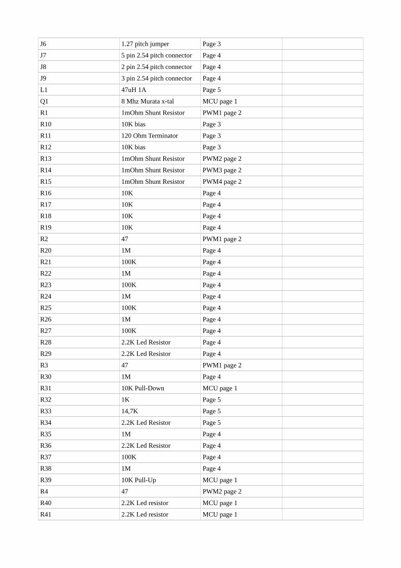
J6 1.27 pitch jumper Page 3
J7 5 pin 2.54 pitch connector Page 4
J8 2 pin 2.54 pitch connector Page 4
J9 3 pin 2.54 pitch connector Page 4
L1 47uH 1A Page 5
Q1 8 Mhz Murata x-tal MCU page 1
R1 1mOhm Shunt Resistor PWM1 page 2
R10 10K bias Page 3
R11 120 Ohm Terminator Page 3
R12 10K bias Page 3
R13 1mOhm Shunt Resistor PWM2 page 2
R14 1mOhm Shunt Resistor PWM3 page 2
R15 1mOhm Shunt Resistor PWM4 page 2
R16 10K Page 4
R17 10K Page 4
R18 10K Page 4
R19 10K Page 4
R2 47 PWM1 page 2
R20 1M Page 4
R21 100K Page 4
R22 1M Page 4
R23 100K Page 4
R24 1M Page 4
R25 100K Page 4
R26 1M Page 4
R27 100K Page 4
R28 2.2K Led Resistor Page 4
R29 2.2K Led Resistor Page 4
R3 47 PWM1 page 2
R30 1M Page 4
R31 10K Pull-Down MCU page 1
R32 1K Page 5
R33 14,7K Page 5
R34 2.2K Led Resistor Page 5
R35 1M Page 4
R36 2.2K Led Resistor Page 4
R37 100K Page 4
R38 1M Page 4
R39 10K Pull-Up MCU page 1
R4 47 PWM2 page 2
R40 2.2K Led resistor MCU page 1
R41 2.2K Led resistor MCU page 1

R42 2.2K Led resistor MCU page 1
R5 47 PWM2 page 2
R6 47 PWM3 page 2
R7 47 PWM3 page 2
R8 47 PWM4 page 2
R9 47 PWM4 page 2
S1 IR2103S PWM1 page 2
S2 IR2103S PWM2 page 2
S3 IR2103S PWM3 page 2
S4 IR2103S PWM4 page 2
SWD1 1.27 pitch Connector MCU page 1
SWD2 1.27 pitch Connector MCU page 1
T1 IRF7862 PWM1 page 2
T2 IRF7862 PWM1 page 2
T3 IRF7862 PWM2 page 2
T4 IRF7862 PWM2 page 2
T5 IRF7862 PWM3 page 2
T6 IRF7862 PWM3 page 2
T7 IRF7862 PWM4 page 2
T8 IRF7862 PWM4 page 2
U1 STM32F405RG MCU page 1
U2 MAX3485 Page 3
U3 LM1117 Page 5
X10 1.27 pitch Male Header Page 2
X11 1.27 pitch Male Header Page 2
X12 ESDA6V1SC5 Page 2
X13 ESDA6V1SC5 Page 2
X14 ESDA6V1SC5 Page 4
X15 LMR14206 Page 5
X16 P4SMA27A Page 2 27V Suppression diode
X17 ESDA6V1SC5 Page 4
X18 ESDA6V1SC5 Page 4
X19 4+ V Suppression Diode Page 5
X2 ESDA6V1SC5 Page 2
X20 Supercap Page 5
X21 12V 1.27 pitch Jumper Page 5
X22 30V 1.27 pitch Jumper Page 5
X3 ESDA6V1SC5 Page 2
X4 INA210 Page 4
X5 INA210 Page 4
X6 INA210 Page 4
X7 INA210 Page 4

X8 1.27 pitch Male Header Page 2
X9 1.27 pitch Male Header Page 2