mc33789, airbag reference demonstrator reference manual · ard system outline airbag reference...
TRANSCRIPT

© Freescale Semiconductor, Inc., 2012. All rights reserved.
Freescale Semiconductor ARDRMReference Manual Rev. 3.0, 4/2012
Airbag Reference Demonstrator
Reference Manual

Important Notice
Freescale provides the enclosed product(s) under the following conditions:
This demonstrator is intended for use of ENGINEERING DEVELOPMENT OR EVALUATION PURPOSES ONLY. It is provided as a sample IC pre-soldered to a printed circuit board to make it easier to access inputs, outputs, and supply terminals. This demonstrator may be used with any development system or other source of I/O signals by simply connecting it to the host MCU or computer board via off-the-shelf cables. This demonstrator is not intended to represent a final design recommendation for any particular application. Final device in an application will be heavily dependent on proper printed circuit board layout and heat sinking design as well as attention to supply filtering, transient suppression, and I/O signal quality.
The goods provided may not be complete in terms of required design, marketing, and or manufacturing related protective considerations, including product safety measures typically found in the end product incorporating the goods. Due to the open construction of the product, it is the user's responsibility to take any and all appropriate precautions with regard to electrostatic discharge. In order to minimize risks associated with the customers applications, adequate design and operating safeguards must be provided by the customer to minimize inherent or procedural hazards. For any safety concerns, contact Freescale sales and technical support services.
As a prototype, this product does not fall within the scope of the European Union directive on electromagnetic compatibility and therefore may not meet the technical requirements of the directive. Please be aware that the products received may not be regulatory compliant or agency certified (FCC, UL, CE, etc.).
Should this demonstrator not meet the specifications indicated in the kit, it may be returned within 30 days from the date of delivery and will be replaced by a new kit.
Freescale reserves the right to make changes without further notice to any products herein. Freescale makes no warranty, representation or guarantee regarding the suitability of its products for any particular purpose, nor does Freescale assume any liability arising out of the application or use of any product or circuit, and specifically disclaims any and all liability, including without limitation consequential or incidental damages. “Typical” parameters can and do vary in different applications and actual performance may vary over time. All operating parameters, including “Typical”, must be validated for each customer application by customer’s technical experts.
Freescale does not convey any license under its patent rights nor the rights of others. Freescale products are not designed, intended, or authorized for use as components in systems intended for surgical implant into the body, or other applications intended to support or sustain life, or for any other application in which the failure of the Freescale product could create a situation where personal injury or death may occur.
Should a Buyer purchase or use Freescale products for any such unintended or unauthorized application, The Buyer shall indemnify and hold Freescale and its officers, employees, subsidiaries, affiliates, and distributors harmless against all claims, costs, damages, and expenses, and reasonable attorney fees arising out of, directly or indirectly, any claim of personal injury or death associated with such unintended or unauthorized use, even if such claim alleges that Freescale was negligent regarding the design or manufacture of the part.
Freescale and the Freescale Logo are registered trademarks of Freescale, Inc. Freescale, Inc. is an Equal Opportunity/Affirmative Action Employer. Freescale and the Freescale Logo are registered in the US Patent and Trademark Office. All other product or service names are the property of their respective owners.
Airbag Reference Demonstrator, Rev. 3.0
2 Freescale Semiconductor

Table of ContentsParagraph Page Number Number
Airbag Reference Demonstrator, Rev. 2.0
Freescale Semiconductor TOC-1
Chapter 1 Introduction1.1 Relevant Documents .......................................................................................................1
Chapter 2 ARD System Outline
Chapter 3 Standard Products Description3.1 MC9S12XEG128MAA - Microcontroller ..........................................................................33.2 MC33789 – Airbag System Basis Chip ...........................................................................3
3.2.1 Power Supply Block...............................................................................................33.2.2 Safing Block...........................................................................................................33.2.3 DC Sensors ...........................................................................................................33.2.4 PSI5 Satellite Sensors ...........................................................................................33.2.5 LIN Physical Layer.................................................................................................33.2.6 Lamp Driver ...........................................................................................................33.2.7 Diagnostics ............................................................................................................3
3.3 MC6801QR2 - ECU Local Sensor ...................................................................................33.4 MC33797 – Four Channel Squib Driver ..........................................................................43.5 MMA5xxxWR2 – High G Satellite Collision Sensor .........................................................4
Chapter 4 Function Description4.1 MC33789 – Airbag System Basis Chip ...........................................................................5
4.1.1 Power Supply – Boost Converter and Energy Reserve.........................................54.1.2 Power Supply – Energy Reserve Capacitor ESR Diagnostic ................................54.1.3 Power Supply – Buck Converter............................................................................54.1.4 Power Supply – SYNC Pulse Supply.....................................................................54.1.5 Power Supply – ECU Logic Supply .......................................................................54.1.6 Safing Block – Sensor Data Thresholds ................................................................64.1.7 Safing Block – Diagnostics ....................................................................................64.1.8 DC Sensors ...........................................................................................................64.1.9 Satellite Sensor Interface.......................................................................................6
LIN Physical Layer 6Lamp Driver 7Diagnostics 7
4.2 MMA6801QR2 – Local ECU Acceleration Sensor ..........................................................74.2.1 Configuration - General .........................................................................................74.2.2 Configuration – Axis Operation..............................................................................74.2.3 Configuration – Arming Operation .........................................................................74.2.4 Configuration – Arming Threshold .........................................................................84.2.5 Status.....................................................................................................................8
4.3 MM33797 – Four Channel Squib Driver (FCS) ...............................................................84.4 MMA5xxxWR2 – High G Satellite Collision Sensor .........................................................8

Table of Contents
Airbag Reference Demonstrator, Rev. 2.0
TOC-2 Freescale Semiconductor
Chapter 5 Airbag Reference Demonstrator Firmware and Setup5.1 Airbag Reference Demonstrator Demo ...........................................................................95.2 Warnings .........................................................................................................................95.3 Airbag Reference Demonstrator PCB Detail Description ..............................................105.4 Airbag Reference Demonstrator - GUI ..........................................................................10
5.4.1 Firmware downloading - GUI version ..................................................................105.4.2 Hardware and Software Setup.............................................................................115.4.3 GUI Demonstration ..............................................................................................11
Debug mode 11Application Mode 12
5.5 Airbag Reference Demonstrator - “Application” .............................................................135.5.1 Firmware Downloading - “Application Demonstrator” ..........................................145.5.2 Airbag Reference Demonstrator - “Application”...................................................15
Chapter 6 Software - Boot Assist Module6.1 Boot Assist Module (BAM) .............................................................................................17
6.1.1 Example of the BAM source code .......................................................................17
Chapter 7 Software - Basic Operating System7.1 Acquisition Phase ..........................................................................................................20
7.1.1 Source code of the Acquisition phase .................................................................217.2 Decision Phase ..............................................................................................................23
7.2.1 Example of the API Source Code Used in Decision Phase - Front Decision ......237.3 Deployment Phase ........................................................................................................24
7.3.1 Example of the API Source Code Used in Deployment Phase ...........................25
Appendix A SW Concept ........................................................................................................27A.1 Airbag System Basis Chip SW Driver ............................................................................27A.2 ASBC API parameters detail descriptions .....................................................................28A.3 Central Accelerometer Driver ........................................................................................31A.4 ACC Parameters Detail Descriptions ............................................................................32A.5 SQUIB Driver .................................................................................................................34A.6 SQUIB Parameters Detail Descriptions .........................................................................35
Appendix B Airbag Reference Demonstrator Implementation details ....................................37B.1 Airbag Reference Demonstrator Schematics ................................................................37B.2 ARD Placement and Layout ..........................................................................................42B.3 Bill of Materials ..............................................................................................................43
Appendix C Acronyms ............................................................................................................45
Introduction
Airbag Reference Demonstrator, Rev. 3.0
Freescale Semiconductor 1
Chapter 1 Introduction
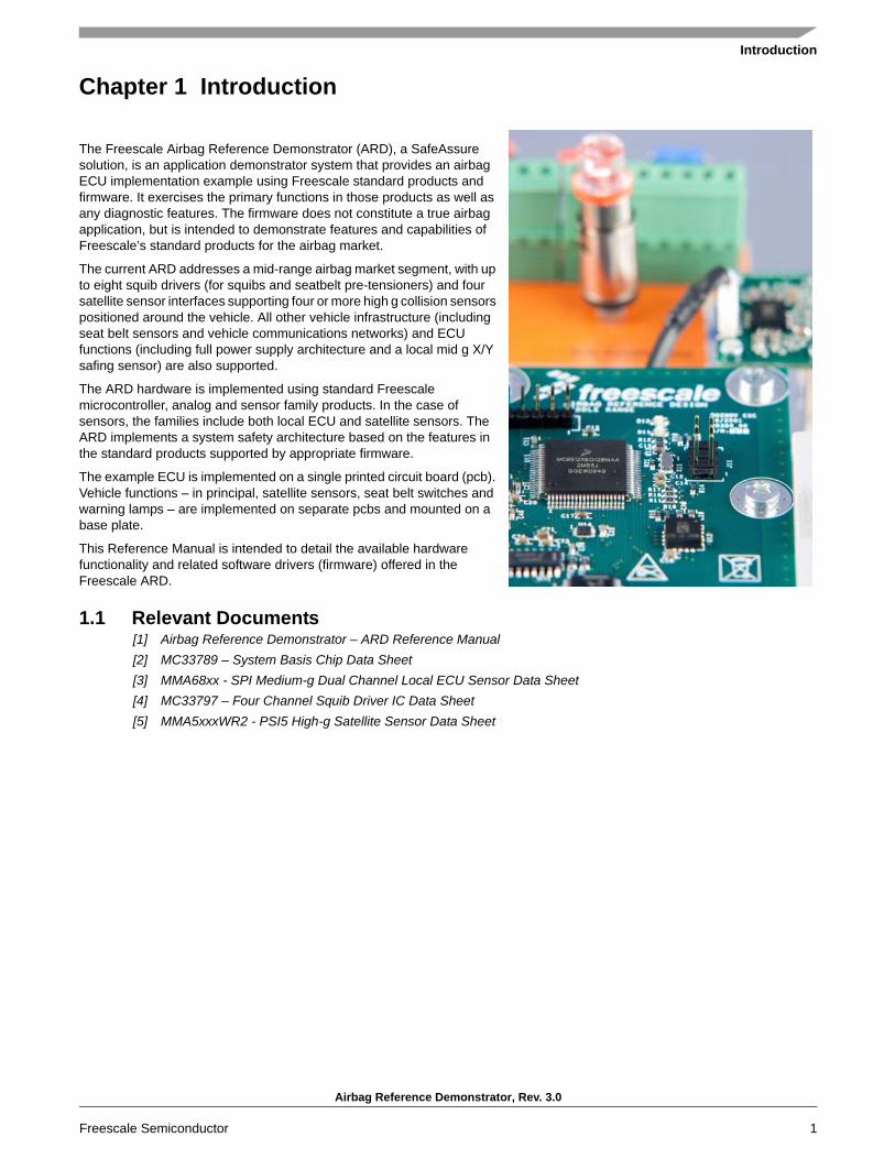
The Freescale Airbag Reference Demonstrator (ARD), a SafeAssure solution, is an application demonstrator system that provides an airbag ECU implementation example using Freescale standard products and firmware. It exercises the primary functions in those products as well as any diagnostic features. The firmware does not constitute a true airbag application, but is intended to demonstrate features and capabilities of Freescale’s standard products for the airbag market.
The current ARD addresses a mid-range airbag market segment, with up to eight squib drivers (for squibs and seatbelt pre-tensioners) and four satellite sensor interfaces supporting four or more high g collision sensors positioned around the vehicle. All other vehicle infrastructure (including seat belt sensors and vehicle communications networks) and ECU functions (including full power supply architecture and a local mid g X/Y safing sensor) are also supported.
The ARD hardware is implemented using standard Freescale microcontroller, analog and sensor family products. In the case of sensors, the families include both local ECU and satellite sensors. The ARD implements a system safety architecture based on the features in the standard products supported by appropriate firmware.
The example ECU is implemented on a single printed circuit board (pcb). Vehicle functions – in principal, satellite sensors, seat belt switches and warning lamps – are implemented on separate pcbs and mounted on a base plate.
This Reference Manual is intended to detail the available hardware functionality and related software drivers (firmware) offered in the Freescale ARD.
1.1 Relevant Documents[1] Airbag Reference Demonstrator – ARD Reference Manual[2] MC33789 – System Basis Chip Data Sheet[3] MMA68xx - SPI Medium-g Dual Channel Local ECU Sensor Data Sheet[4] MC33797 – Four Channel Squib Driver IC Data Sheet[5] MMA5xxxWR2 - PSI5 High-g Satellite Sensor Data Sheet

ARD System Outline
Airbag Reference Demonstrator, Rev. 3.0
2 Freescale Semiconductor
Chapter 2 ARD System Outline
The high level system block diagram here outlines the way the Freescale standard products are used to implement an example airbag ECU.
• MC9S12XEG128MAA – Microcontroller• MC33789 – Airbag System Basis Chip• MMA6801QR2 – ECU Local X/Y Accelerometer• MM33797 – Four Channel Squib Driver• CAN Phy – High Speed CAN Physical Layer• MMA5xxxWR2 – High G Collision Satellite Sensor

Standard Products Description
Airbag Reference Demonstrator, Rev. 3.0
Freescale Semiconductor 3
Chapter 3 Standard Products Description
All devices used in the Freescale ARD are standard products and those devices are described here.
3.1 MC9S12XEG128MAA - MicrocontrollerThis microcontroller is a member of the highly successful S12 family of automotive microcontrollers that includes flexible Flash memory, which allows cost efficient implementation of internal EEPROM emulation, and a rich selection of peripherals to support an efficient system connection.
3.2 MC33789 – Airbag System Basis ChipThis device implements all vehicle sensor interfaces and the airbag system support functions.
3.2.1 Power Supply Block• A switch mode power supply DC-DC converter in a boost configuration to generate the high voltage level (33 V), in
which energy is stored in the autarky capacitor, and used to allow continued operation of the system for a defined time following a collision, which leads to disconnection of the battery
• A switch mode power supply DC-DC converter in a buck configuration, to efficiently step down the boost supply to a level suitable for supplying the satellite sensors interfaces (9.0 V) and further regulators, for the local ECU supplies
• A charge pump to double the output of the buck converter, to supply the necessary voltage for the PSI5 sync pulse generation (18 V), to facilitate operation of the satellite sensor interfaces in synchronous mode, and therefore more than one sensor per interface. This is only enabled if more than one satellite sensor per interface is required
• A linear regulator to provide the local logic supply (5.0 V) for ECU devices i.e. microcontroller, local sensor, squib driver,...
3.2.2 Safing BlockThis block includes an SPI monitor which inputs sensor data read by the microcontroller over the sensor SPI interface, and compares it to pre-defined threshold acceleration values for each local and vehicle collision sensor. Based on this comparison, where the threshold is exceeded in three consecutive acquisition cycles, the system is armed by enabling the safing outputs, which in turn enables the squib drivers, so that the application can fire the necessary squibs based on the airbag algorithm results.
3.2.3 DC SensorsA low speed (D.C.,) interface which connects to resistive and hall effect sensors which are used to check whether seat belts are being worn through seat belt switches and seat position through seat track sensors.
3.2.4 PSI5 Satellite SensorsSatellite sensors interfaces, which connect to collision sensors distributed around the vehicle. The interfaces implement the PSI5 V1.3 specification, and can operate in asynchronous and synchronous modes.
3.2.5 LIN Physical LayerFor connection to vehicle diagnostic interface (K-line) or Occupant Classification System.
3.2.6 Lamp DriverA high or low side driver which can be configured in hardware which supports PWM driven LED or warning lamp driver.
3.2.7 DiagnosticsA number of measures which allow diagnosis of implemented functions on the system basis chip, e.g. all voltage supplies including power transistor temperature monitors, autarky capacitor ESR, etc.
3.3 MC6801QR2 - ECU Local SensorThe ECU local sensor acceleration data is used by the airbag application to cross check the acceleration data received from the satellite collision sensors, to confirm that a collision is really happening, and that airbags need to be deployed.
Standard Products Description
Airbag Reference Demonstrator, Rev. 3.0
4 Freescale Semiconductor
The local sensor used in the ARD is dual channel, and confirms both frontal and side impacts. In addition, the MC6801QR2 includes it’s own safing block, which will compare the measured acceleration to configurable thresholds and set safing outputs accordingly. This function is used in the ARD to enable the squib drivers, and therefore be an independent part of the system safing architecture – both the safing blocks in the system basis chip and in the local sensor must enable the squib drivers before the application is able to fire the appropriate squibs.
3.4 MC33797 – Four Channel Squib DriverEach channel consists of a high side and a low side switch. The ARD uses two MC33797 devices connected in cross-coupled mode, i.e. high side switch from one device and low side switch from the other, connected to each squib or seat belt pre-tensioner. This ensures no single point of failure in the squib output stage.
The MC33797 implements a comprehensive set of diagnostic features that allows the application to ensure that the squib driver stage is operating correctly.
3.5 MMA5xxxWR2 – High G Satellite Collision SensorA single channel acceleration sensor operating in the range of 60 – 480g (depending on G-cell fitted), which includes a PSI5 V1.3 interface for direct connection to the system basis chip. The device can operate in either asynchronous (point-to-point single sensor connection) or synchronous (bus mode with multiple sensors connected to each interface) mode. The device can be used either for frontal collisions or side impacts.

Function Description
Airbag Reference Demonstrator, Rev. 3.0
Freescale Semiconductor 5
Chapter 4 Function Description
The following section describes individual functions and how they relate to firmware.
4.1 MC33789 – Airbag System Basis Chip
4.1.1 Power Supply – Boost Converter and Energy Reserve
Default setting for the boost converter is ON and will start up when VBATT exceeds a predefined limit. Initially, the boost converter will charge a small capacitor. Default setting for the energy reserve is OFF to prevent current inrush at key on. The firmware must turn the energy reserve on through the PS_CONTROL register once VBOOST is stable. Firmware can monitor VBOOST through the analog output pin selected through AI_CONTROL register. After the energy reserve is turned on, the large energy reserve capacitor (min 2200 μF) will be charged.
4.1.2 Power Supply – Energy Reserve Capacitor ESR Diagnostic
During ESR diagnostic, the energy reserve capacitor is slightly discharged and the firmware can calculate, based on the discharge rate, the value of the capacitor’s effective series resistance – this is a measure of the condition of the capacitor.
4.1.3 Power Supply – Buck Converter
Default setting for the buck converter is ON and will start up when VBOOST starts up. Firmware can monitor VBUCK through the analog output pin selected through AI_CONTROL register.
4.1.4 Power Supply – SYNC Pulse Supply
Default setting for the SYNC supply is OFF. Firmware needs to turn the SYNC supply on through PS_CONTROL register only if the satellite sensors are operating in synchronous mode. Firmware can monitor VSYNC through the analog output pin selected through the AI_CONTROL register.
4.1.5 Power Supply – ECU Logic Supply
The internal ECU logic supply is always on and firmware has no configuration to perform.
Device Function Config Register Diagnosis Comment
MC33789 Energy Reserve Supply PS_CONTROL AI_CONTROL
Device Function Config Register Diagnosis CommentMC33789 Energy Reserve Capacitor
DiagnosticESR_DIAG ESR_DIAG
Device Function Config Register Diagnosis Comment
MC33789 Satellite Sensor Supply PS_CONTROL AI_CONTROL
Device Function Config Register Diagnosis CommentMC33789 Satellite Sensor SYNC Pulse
SupplyPS_CONTROL AI_CONTROL
Device Function Config Register Diagnosis CommentMC33789 Linear Regulator - -

Function Description
Airbag Reference Demonstrator, Rev. 3.0
6 Freescale Semiconductor
4.1.6 Safing Block – Sensor Data Thresholds
In order to be able to change the sensor data threshold value or values at which the ARM/DISARM pin are set to active (i.e. the system is armed when a sensor value exceeds the defined threshold), a secure firmware sequence must be carried out to unlock the threshold register using T_UNLOCK. Once that is done, the threshold can be changed by firmware through the SAFE_TH_n register.
NOTEThere is no special firmware required to input sensor data into the safing block. The SPI protocol on the sensor SPI interface is the same to both the local sensor and the satellite sensor interfaces on the system basis chip, and whenever the microcontroller reads a sensor value, the response from the sensor or system basis chip is recognized as being sensor data, and is automatically read into the safing block. The only requirement the application has to meet is that the sensor data is read in the correct sequence, starting with the local sensor X-axis data followed by the Y-axis, and then the satellite sensor interfaces on the system basis chip.
4.1.7 Safing Block – Diagnostics
The firmware has the capability to change the mode in which the safing block is operating, so that diagnosis of the ARM/DISARM pins can be diagnosed or the scrapping mode (i.e. the system is armed when no sensor data exceeds any threshold, used to fire all squibs when a vehicle is being scrapped) can be entered. Either of these changes is only possible at startup prior to the safing block entering normal operation.
4.1.8 DC Sensors
The firmware must select which sensor is active and which supply voltage is used on that sensor through the DCS_CONTROL register. The firmware must also select the correct sensor to be read through the analog output pin using the AI_CONTROL register. Note that both registers can be returned to their default state by a correct write to the DIAG_CLR register.
4.1.9 Satellite Sensor Interface
The firmware must select the correct mode of operation of the satellite sensor interface and enable each interface individually. The interfaces should be enabled one at a time to reduce current inrush.
When the interface is enabled, the satellite sensor will automatically send it’s initialization data, and the firmware must handle this data to ensure the sensor is operating correctly.
4.1.9.1 LIN Physical Layer
Device Function Config Register Diagnosis CommentMC33789 Threshold T_UNLOCK,
SAFE_TH_n-
Device Function Config Register Diagnosis CommentMC33789 Linear Regulator - SAFE_CTL
Device Function Config Register Diagnosis CommentMC33789 Seat belt/Seat track sensor
interfaceDCS_CONTROL,
AI_CONTROL-
Device Function Config Register Diagnosis CommentMC33789 Satellite Sensor LINE_MODE,
LINE_ENABLE-
Device Function Config Register Diagnosis CommentMC33789 LIN physical layer LIN_CONFIG -

Function Description
Airbag Reference Demonstrator, Rev. 3.0
Freescale Semiconductor 7
The firmware has the potential to change the configuration of the LIN physical layer, but the default setting is the most common configuration.
A special mode exists which allows the raw Manchester encoded data from a satellite sensor to be monitored on the LIN output pin, but this is only for the debug operation.
4.1.9.2 Lamp Driver
The firmware must configure whether the driver is a high or low side switch, and the PWM output duty cycle. In the response to the command, the firmware can check that high or low thresholds on the pins have been exceeded, and whether an over-temperature shutdown has occurred.
As part of the application, the warning lamp should be turned on at key on, kept illuminated until the startup diagnostic procedure has completed, and the system is ready to start operating.
4.1.9.3 Diagnostics
The firmware can monitor the operation of the main ASIC through the STATUS and AI_CONTROL registers.
4.2 MMA6801QR2 – Local ECU Acceleration SensorThe local ECU acceleration sensor is a dual channel device which also includes a safing block. At start up, configuration, offset cancellation, and self test of the device, take place before the configuration is complete (’ENDINIT’ set) and the device goes into normal operation.
4.2.1 Configuration - General
The general configuration sets up the data format, whether offset monitoring is enabled, and the functionality of the ARM_X and ARM_Y output pins. When configuration is complete, the ENDINIT bit is set and this locks out access to the configuration registers
4.2.2 Configuration – Axis Operation
The axis operation configuration triggers self-test and selects one of the low pass filter options for each axis.
4.2.3 Configuration – Arming Operation
The arming operation configuration defines the arming pulse stretch period and the arming window, which has different meanings, depending on which arming mode is configured.
Device Function Config Register Diagnosis CommentMC33789 Lamp driver GPOn_CTL GPOn_CTL
Device Function Config Register Diagnosis CommentMC33789 Diagnostics - STATUS,
AI_CONTROL
Device Function Config Register Diagnosis CommentMMA6801QR2 Configuration DEVCFG -
Device Function Config Register Diagnosis CommentMMA6801QR2 Configuration DEVCFG_X,
DEVCFG_Y-
Device Function Config Register Diagnosis CommentMMA6801QR2 Configuration ARMCFG_X,
ARMCFG_Y-

Function Description
Airbag Reference Demonstrator, Rev. 3.0
8 Freescale Semiconductor
4.2.4 Configuration – Arming Threshold
For each axis, both the positive and negative threshold can be set above which and when the arming window requirements are met, the arm outputs will be set to active as defined in the arming operations register.
In the startup phase, the threshold can be set to such a level that when the self test deflection is triggered, the arming outputs will become active. This can be used as part of the self-test at startup. After completion of the self test, thresholds should be set back to the correct application values, and before the configuration is complete, by setting the ‘ENDINIT’ bit, after which no further configuration changes can be made.
The complete startup and self-test procedure is described in the ARD specification (Airbag Reference Design).
Note that after the configuration is complete and the ‘ENDINIT’ bit is set, a CRC check of the configuration is carried out in the background, which will lead to an error in the status register if a configuration bit flips.
4.2.5 Status
Internal errors are flagged in the DEVSTAT register.
4.3 MM33797 – Four Channel Squib Driver (FCS)The ARD uses two FCS in cross-coupled mode to implement eight squib drivers.
The FCS is addressed using an 8-bit SPI interface over which commands and data are sent.
The only configuration possible is the time the device remains enabled after the fire enable (FEN1, FEN2) pins have been activated. This is equivalent to the arming pulse stretch time applied to the safing output on both the system basis chip and the local ECU sensor. Two commands are required to change this time – first is an unlock command and second is the programmed time between 0 and 255 ms. Default is 0 ms.
Firing the squibs also requires two commands – the first arms one of the banks of drivers, the second turns on the required switches. More than one switch can be turned on by a single command.
The majority of the commands relate to diagnostics of the FCS and the connected squibs. A full list of diagnostic commands is available in the ARD specification (Airbag Reference Design).
4.4 MMA5xxxWR2 – High G Satellite Collision SensorNo configuration of the MMA5xxxWR2 is possible. All configuration of the device is done off line prior to assembly in the system.
As soon as the device is switched on, it will begin an internal configuration and self test, and also sends initialization data, which is received in the system basis chip and checked by the application. Once the device has completed sending the initialization data, which concludes with an OK or NOK message, it enters normal operation and starts sending sensor data, either autonomously if in asynchronous mode, or in response to SYNC pulses on the satellite sensor interface if in synchronous mode.
Device Function Config Register Diagnosis CommentMMA6801QR2 Configuration ARMT_XP, ARMT_XN
ARMT_YP, ARMT_YN-
Device Function Config Register Diagnosis CommentMMA6801QR2 Status - DEVSTAT

Airbag Reference Demonstrator Firmware and Setup
Airbag Reference Demonstrator, Rev. 3.0
Freescale Semiconductor 9
Chapter 5 Airbag Reference Demonstrator Firmware and Setup
5.1 Airbag Reference Demonstrator DemoThe ECU is implemented on a single printed circuit board (PCB). Vehicle functions - in principal, satellite sensors, seat belt switches, and warning lamp - are implemented on separate PCBs and mounted on a base Plexiglas plate. This set is placed on rubber columns on the heavy aluminium base plate. Squibs are replaced by resistors with corresponding values to actual squibs.
Figure 5-1. Airbag Reference Demonstrator Demo Description
5.2 WarningsThe user should be aware of:
• Operating power supply voltage from 6.0 to 20 V DC continuous• Nominal voltage 12 V DC (automotive battery)• Observe power supply voltage polarity. The devices have incorporated reverse battery protection, however, on-board
electrolytic capacitors may be damaged.
Rear Left Satellite SensorDriver Satellite Sensor
Passenger Satellite SensorWarning Lamp
Rear Left Pretensioner SQUIB
Rear Left SQUIB
Rear Right Pretensioner SQUIB
Rear Right SQUIBDriver SQUIB
Driver Pretensioner SQUIB
Power Supply Voltage
Passenger SQUIB
Passenger Pretensioner SQUIB
Seat Belt Buckle Sensors
Rear Right Satellite Sensor

Airbag Reference Demonstrator Firmware and Setup
Airbag Reference Demonstrator, Rev. 3.0
10 Freescale Semiconductor
5.3 Airbag Reference Demonstrator PCB Detail Description
Figure 5-2. ARD PCB Detail Description
5.4 Airbag Reference Demonstrator - GUIFreeMASTER GUI application can work in 2 modes:
• Debug Mode - GUI firmware together with GUI applications allow debug of the main ARD devices - MC33789 (Airbag System Basis Chip), MC33797 (Four Channel Squib Driver), and MMA6801QR2 (Central Accelerometer). The device registers are readable and configurable. At all times, the registers remain visible and can be monitored. This is intended to aid engineers understand both the hardware and software routines.
• Application Mode - application mode allows the users to view acceleration data from central and satellite accelerometers. These numerical values are also plotted on a graph, which allows informative outlook to the acceleration levels of all sensors. Deployment of squibs is simulated in this mode on a simple car model picture, using pictures of both front and side deployments.
5.4.1 Firmware downloading - GUI versionWhen using the Code Warrior Development Studio S12(X) first time, install the Code Warrior IDE from the Freescale web page.
1. From CD open Code Warrior project file: “\ARD_Firmwares\AirbagReferenceDesign_GUIFirmware\ard_gui_middle\ard_gui_middle.mcp”.
2. Connect the DC power supply 12 V. Observe polarity: red is positive, blue or black is negative.3. Connect attached P&E micro debugger to J11 connector on the ARD main board and plug the USB cable to the PC
USB port.4. Press function key F5 or go to “Project” and select “Debug”.5. After finish of the downloading, unplug P&E micro debugger from the J11 port.
BDM Multi-linkConnector
Central AccelerometerMMA6801QR2
CAN Transceiver
Four ChannelSquib Driver #2MC33797
Energy Reserve Capacitors
Airbag SystemBasis ChipMC33789
RS232 Communication Port
Four ChannelSquib Driver #1MC33797
MicrocontrollerMC9S12XEG128
OnBoard LED1OnBoard LED2
Airbag Reference Demonstrator Firmware and Setup
Airbag Reference Demonstrator, Rev. 3.0
Freescale Semiconductor 11
NOTEThis firmware is loaded into Airbag Reference Demonstrator Demo after delivery and immediately ready for using with the FreeMASTER GUI application without doing steps above.
5.4.2 Hardware and Software SetupWhen using the FreeMASTER first time, install the FreeMASTER tool from the enclosed CD, as well as the USB drivers. If you have already done this, proceed to point 5.
1. From the CD run file: FreeMASTER\FMASTERSW.exe and leave all steps as the default.2. Connect the DC power supply 12 V. Observe polarity: red is positive, blue or black is negative.3. Plug the USB cable to the PC USB port. On the screen bottom right-hand corner will appear the message: “Found New
Hardware”. Please install the USB drivers located in the enclosed CD, directory \USB_Driver. USB driver is installed twice. Once itself USB driver and second virtual RS232 COM port.
4. PC desktop, mouse right click the icon “My computer” and select “Properties”. The “System Properties” window will open. Select the tab “Hardware” and then click on the “Device Manager” button. In a new window, expand the “Ports (COM & LPT)”. If you have installed the USB drivers properly, the virtual COM ports will be listed, e.g. “USB Serial Port (COMx)”. The PC assignees COMx port number. Note the port number used for FreeMASTER control pages configuration.
5. Copy folder “AirbagReferenceDesign_GUI\” from the CD to your local hard drive. You will be able to save the FreeMASTER configuration.
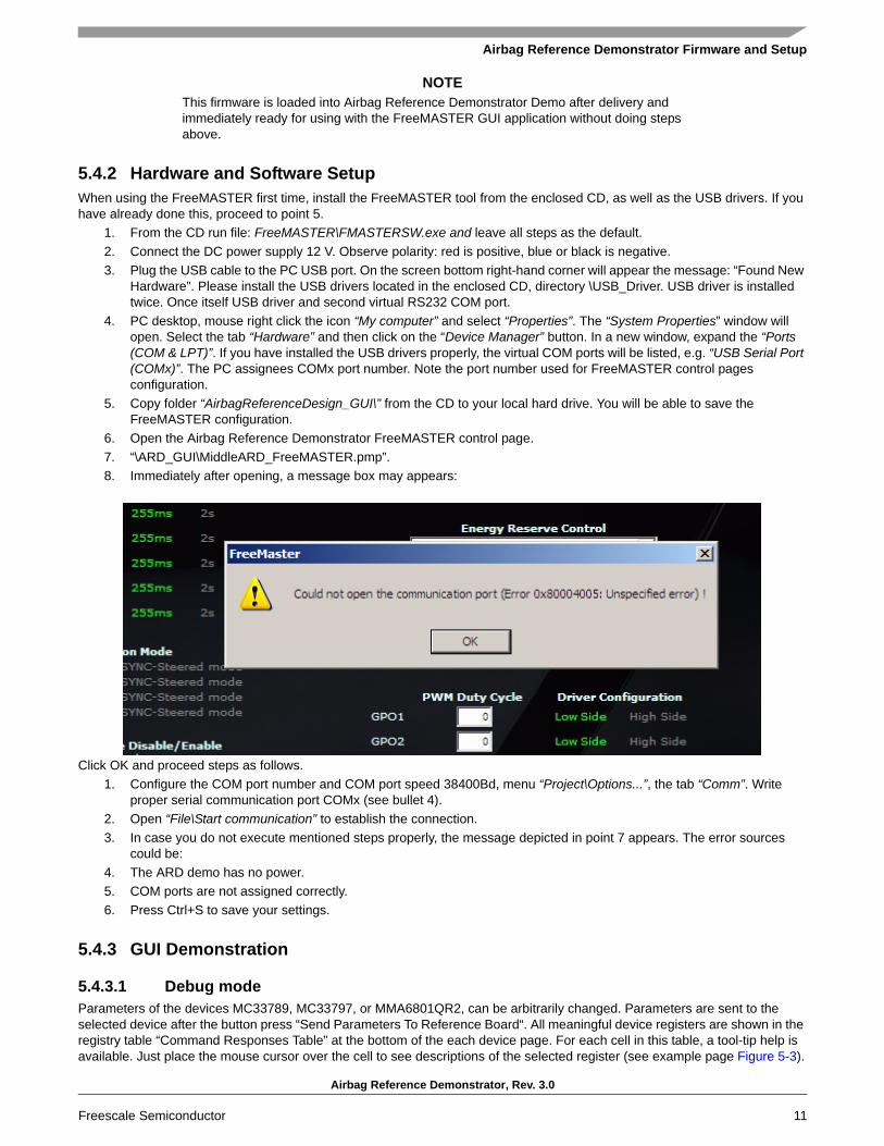
6. Open the Airbag Reference Demonstrator FreeMASTER control page.7. “\ARD_GUI\MiddleARD_FreeMASTER.pmp”.8. Immediately after opening, a message box may appears:
Click OK and proceed steps as follows.1. Configure the COM port number and COM port speed 38400Bd, menu “Project\Options...”, the tab “Comm”. Write
proper serial communication port COMx (see bullet 4).2. Open “File\Start communication” to establish the connection. 3. In case you do not execute mentioned steps properly, the message depicted in point 7 appears. The error sources
could be:4. The ARD demo has no power.5. COM ports are not assigned correctly.6. Press Ctrl+S to save your settings.
5.4.3 GUI Demonstration
5.4.3.1 Debug modeParameters of the devices MC33789, MC33797, or MMA6801QR2, can be arbitrarily changed. Parameters are sent to the selected device after the button press “Send Parameters To Reference Board“. All meaningful device registers are shown in the registry table “Command Responses Table” at the bottom of the each device page. For each cell in this table, a tool-tip help is available. Just place the mouse cursor over the cell to see descriptions of the selected register (see example page Figure 5-3).

Airbag Reference Demonstrator Firmware and Setup
Airbag Reference Demonstrator, Rev. 3.0
12 Freescale Semiconductor
Figure 5-3. FreeMASTER Debug Page for the MC33789 Device
NOTEAfter starting the watchdog refresh (Watchdog -> Enable), parameters “Safing Thresholds” and “Dwell Extensions” in MC33789 can not be changed.
5.4.3.2 Application ModeThis simple ARD application mode allows to (see Figure 5-4):
• View acceleration data from central and satellite accelerometers. These numerical values are displayed in points where sensors should be placed inside the car.
• View acceleration data plotted on a graph, which allows informative outlook to the acceleration levels of all sensors and a simple car model simulation of the both front and side collisions. Plotted data is only informative, since transferred data from sensors is averaged for illustration of ARD functionality only.
• Simulate deployment of an airbag when the acceleration data reaches the threshold values. These thresholds are set to very low limits, so the soft hit to sensor place by fingers or by rubber hand tool cause relevant airbags “deployment”. This deployment is shown as inflated bags picture in a place where the “collision” occurred. Any “collision” at the driver or passenger place causes inflation of two front airbags. Impact from left side causes inflation of the left side airbags, and from right side causes deployment of the right sides airbags. Anytime after deployment, simulation is possible to reset an inflated bag or bags by pressing button “Reset Deployed Airbags”.

Airbag Reference Demonstrator Firmware and Setup
Airbag Reference Demonstrator, Rev. 3.0
Freescale Semiconductor 13
Figure 5-4. FreeMASTER Application Mode
NOTEIn this GUI mode during simulated airbags “deployment”, the relevant squibs drivers are not activated.
5.5 Airbag Reference Demonstrator - “Application”GUI firmware was designed specifically for communication with the GUI, but firmware uses the same API and low level drivers, as the version described in this chapter, which is intended to demonstrate the functionality of the hardware in an application environment.
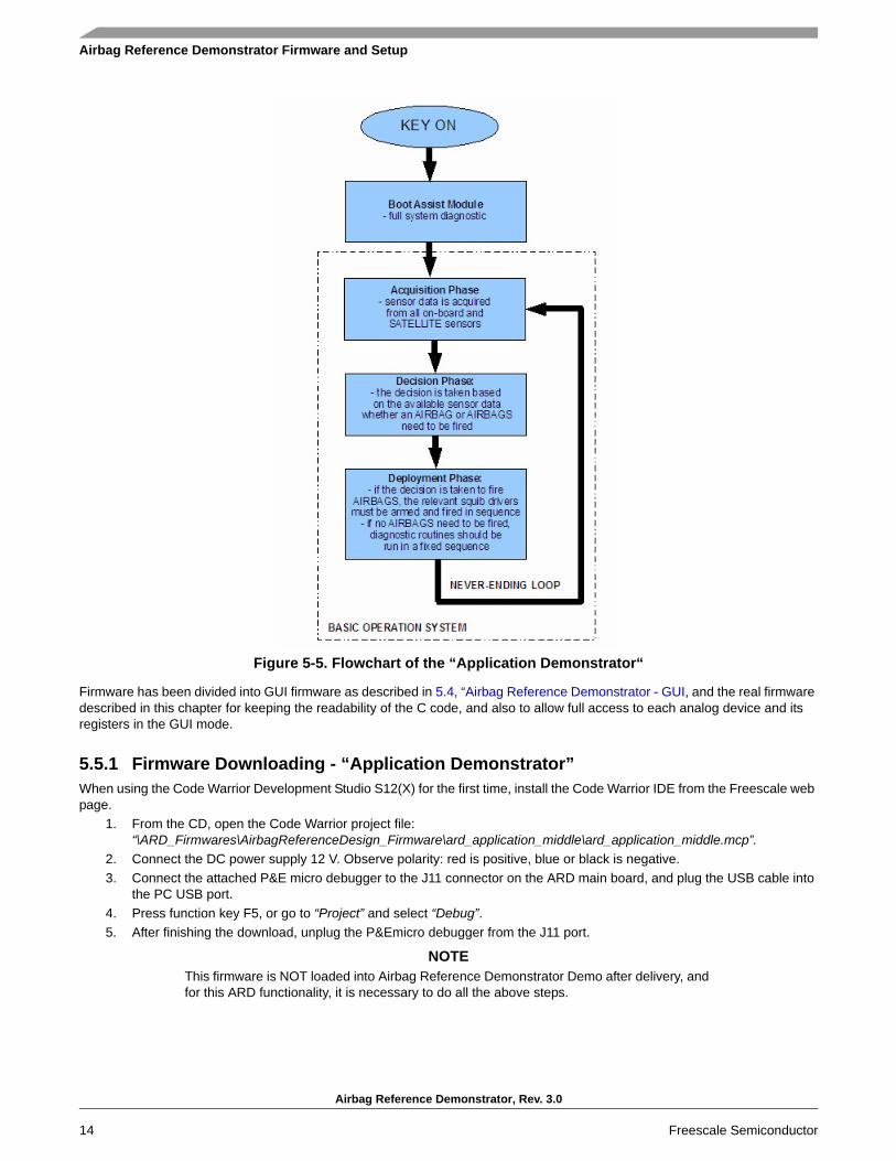
The ARD application demonstrator firmware goes through the phases as indicated in Figure 5-5.
Airbag Reference Demonstrator Firmware and Setup
Airbag Reference Demonstrator, Rev. 3.0
14 Freescale Semiconductor
Figure 5-5. Flowchart of the “Application Demonstrator“
Firmware has been divided into GUI firmware as described in 5.4, “Airbag Reference Demonstrator - GUI, and the real firmware described in this chapter for keeping the readability of the C code, and also to allow full access to each analog device and its registers in the GUI mode.
5.5.1 Firmware Downloading - “Application Demonstrator”When using the Code Warrior Development Studio S12(X) for the first time, install the Code Warrior IDE from the Freescale web page.
1. From the CD, open the Code Warrior project file: “\ARD_Firmwares\AirbagReferenceDesign_Firmware\ard_application_middle\ard_application_middle.mcp”.
2. Connect the DC power supply 12 V. Observe polarity: red is positive, blue or black is negative.3. Connect the attached P&E micro debugger to the J11 connector on the ARD main board, and plug the USB cable into
the PC USB port.4. Press function key F5, or go to “Project” and select “Debug”.5. After finishing the download, unplug the P&Emicro debugger from the J11 port.
NOTEThis firmware is NOT loaded into Airbag Reference Demonstrator Demo after delivery, and for this ARD functionality, it is necessary to do all the above steps.

Airbag Reference Demonstrator Firmware and Setup
Airbag Reference Demonstrator, Rev. 3.0
Freescale Semiconductor 15
5.5.2 Airbag Reference Demonstrator - “Application”This real ARD application demonstrator allows simple user friendly verification of the functionality. Threshold values for initiation of the airbag deployment are set at very low level limits, so simulation can take place without major car collision impact. Just a soft hit to the sensor place by a finger, or by a rubber tool cause relevant airbag “deployment”.
All ARD SW processes work in real time - reading acceleration values, evaluation and deployment of the squib drivers. This ARD application works independently without communication with the GUI. Evaluation of a collision is indicated only by RED or YELLOW on-board LEDs on the main ECU board.
Lighting up the yellow LED means that impact occurred from the left or right rear side, lighting of the red denotes the collision occurred from front side. Both LEDs switched on it means that the collision occurred from front and also from left or right rear side.
In this demonstrator mode, the relevant squibs (represented by equivalent resistors) are fired, means the firing current flows through resistors, representing the actual airbag squibs.
For a collision simulation (see Figure 5-6):• hit the rear left sensor place => on-board YELLOW LED turns on• hit the rear left sensor place => on-board YELLOW LED turns on• hit the driver or passenger sensor place => on-board RED LED turns on
Simultaneously with on-board LEDs, the warning lamp is also turned on.
NOTEKeep in mind that in case of a disconnection of the main supply voltage source (possible automotive battery), the whole system is still powered by reserve capacitors in the Autarky mode (roughly for 10 seconds), so it is possible to disconnect the power supply and still operate the demonstrator.
After the power disconnection, please wait before turning off all on-board LEDs, and then reconnecting the power supply.

Airbag Reference Demonstrator Firmware and Setup
Airbag Reference Demonstrator, Rev. 3.0
16 Freescale Semiconductor
Figure 5-6. Demonstration of the Airbag Application
Hitting this point causesREAR RIGHT DEPLYOMENT
Hitting this point causesREAR LEFT DEPLYOMENT
Yellow LED Red LED
Hitting this point (driver) causesFRONT DEPLOYMENT
Hitting this point (passenger) causesFRONT DEPLOYMENT

Software - Boot Assist Module
Airbag Reference Demonstrator, Rev. 3.0
Freescale Semiconductor 17
Chapter 6 Software - Boot Assist Module
6.1 Boot Assist Module (BAM)The Boost Assist Module controls start up of the demonstrator. During start up of the system, the power supply chain (boost converter, buck converter, and linear regulator) starts automatically once the input to ASBC device has exceeded 5.2 V for more than 1.0 ms. Once stabilized, system RESET is released, allowing the microcontroller to start operating.
Once operating, the microcontroller can continue with the start up process. The microcontroller must turn on the charging of the main energy reserve capacitor and satellite sensors (if present), configure acceleration thresholds for the safing block in central accelerometer, and run a complete diagnostic check of the system before turning off the driver warning lamp.
Once the driver warning lamp has been switched off, the system is considered ‘ARMED’ and able to fire squibs, if no system fault is found prior to a collision, this leads to the warning lamp being switched on again.
Figure 6-1. Boot Startup Architecture
6.1.1 Example of the BAM source code
This example of the BAM consists of initializing of all the devices on the main ECU board. Each device calls for one standalone initialization API function, and other required features are configured by separate driver functions.
Checking if devices work properly are performed. If all required parameters are set correctly, no device reports any internal error, and if all device tests and their peripherals are without error, the ARD application continues the BOM phase. Otherwise, the systems halts and does not continue its operation.

Software - Boot Assist Module
Airbag Reference Demonstrator, Rev. 3.0
18 Freescale Semiconductor
/* Init Airbag System Basis Chip */
ret_asbc = Asbc_Init(ARD_SPI_ASBC, &Asbc_Config[0]); /* initialization of the ASBC device MC33789 */
if(ret_asbc == ASBC_OK){
/* Setup ASBC device */
Gpt_Enable(); /* enable ASBC watchdog refresh - enable RTI interrupt */
ret_asbc = Asbc_SetSafingMode(ARD_SPI_ASBC, ASBC_SAFING_CHANGE_TO_SAFING_MODE,
ASBC_SAFING_TEST_DIS, ASBC_SAFING_ARM_OUT_0); /* set ASBC device to the
Safing mode, disable FEN/FDIS arming testing mode */
if(ret_asbc == ASBC_NOT_OK) Ard_Status = ARD_ERROR; /* ASBC device is not in SAFING mode */
ret_asbc = Asbc_SetVregMode(ARD_SPI_ASBC, &Asbc_VregConfig[0]); /* configure voltage regulators */
ret_asbc = Asbc_SetGpo(ARD_SPI_ASBC, ASBC_GPO_1, ASBC_GPO_DC_66_7, ASBC_GPO_LS_DRIVER); /* driver
warning lamp set ON (duty cycle 66,7%) */
ret_asbc = Asbc_SetGpo(ARD_SPI_ASBC, ASBC_GPO_2, ASBC_GPO_DC_OFF, ASBC_GPO_HS_DRIVER); /* unused
output */
ret_asbc = Asbc_SetLinMode(ARD_SPI_ASBC, &Asbc_LinConfig[0]); /* LIN physical layer configuration */
ret_asbc = Asbc_SetPsi5Mode(ARD_SPI_ASBC, &Asbc_Psi5Config[1]); /* configure PSI5 interface - turn satellite
sensors interface OFF */
/* Check ASBC device */
/* Read System Basis Chip statuses */
Asbc_Status.Asbc_StatFullEnable = ASBC_STAT_FULL_EN; /* truncated status of the ASBC device */
ret_asbc = Asbc_GetStatus(ARD_SPI_ASBC, &Asbc_Status); /* common status of the ASBC device */
ret_asbc = Asbc_GetLinStatus(ARD_SPI_ASBC, &Asbc_LinStatus); /* get LIN physical layer settings */
ret_asbc = Asbc_GetPsi5Status(ARD_SPI_ASBC, &Asbc_Psi5Status); /* the status of the ASBC PSI5 interface */
ret_asbc = Asbc_GetVregStatus(ARD_SPI_ASBC, ASBC_VREG_ESR_DIS, &Asbc_VregStatus); /* read status of the
ASBC voltage regulators and measure state of the Energy Reserve capacitor */
}else{
Ard_Status = ARD_ERROR; /* Airbag System Basis Chip initialization failed */
}
/* Init Central Accelerometer */
if(Ard_Status != ARD_ERROR){ /* if the system basis chip started without error */
ret_acc = Acc_Init(ARD_SPI_ACC, &Acc_Config[0]); /* setup central accelerator device */
ret_acc = Acc_GetStatus(ARD_SPI_ACC, &Acc_Status); /* read the complete statuses of the ACC device */
if(ret_acc != ACC_OK){ /* initalization or get ACC status failed */
Ard_Status = ARD_ERROR; /* Central Accelerometer initialization failed */

Software - Boot Assist Module
Airbag Reference Demonstrator, Rev. 3.0
Freescale Semiconductor 19
}
}
/* Init SQUIB drivers */
if(Ard_Status != ARD_ERROR){ /* if the ASBC and ACC started without error */
ret_squib = Squib_Init(ARD_SPI_SQUIB1); /* the function initializes the SQUIB1 driver - device MC33797 */
if(ret_squib == SQB_OK){ /* if SQUIB1 initialized without any errors */
ret_squib = Squib_GetStatus(ARD_SPI_SQUIB1, &Sqb1_Status); /* get status of the 1A, 1B, 2A, 2B of the SQUIB1 */
if(ret_squib == SQB_OK){ /* if return from the Squib_GetStatus are without error */
ret_squib = Squib_Init(ARD_SPI_SQUIB2); /* the function initializes the SQUIB2 driver - device MC33797 */
if(ret_squib == SQB_OK){ /* if SQUIB2 initialized without any errors */
ret_squib = Squib_GetStatus(ARD_SPI_SQUIB2, &Sqb2_Status); /* get status of the 1A, 1B, 2A, 2B of the SQUIB2 */
if(ret_squib != SQB_OK){ /* if error return from the Squib_GetStatus */
Ard_Status = ARD_ERROR;
}
}else Ard_Status = ARD_ERROR;
}else Ard_Status = ARD_ERROR;
}else Ard_Status = ARD_ERROR;
}
if(Ard_Status != ARD_ERROR){ /* if SQUIBs devices started without error - check all SQUIB1 and SQUIB2 parameters */
/* SQUIB1 short to GND or to BATTERY */
if(Sqb1_Status.Squib_1AShBatt == SQB_SH_TO_BATT_FAULT) Ard_Status = ARD_ERROR;
if(Sqb1_Status.Squib_1AShGnd == SQB_SH_TO_GND_FAULT) Ard_Status = ARD_ERROR;
if(Sqb1_Status.Squib_1BShBatt == SQB_SH_TO_BATT_FAULT) Ard_Status = ARD_ERROR;
….
…
…

Software - Basic Operating System
Airbag Reference Demonstrator, Rev. 3.0
20 Freescale Semiconductor
Chapter 7 Software - Basic Operating System
Once the start up phase has completed and the warning lamp has been switched off, the system is ready to operate normally, at which time the airbag control algorithm will be running.
The control algorithm consists of three phases:• Acquisition Phase – sensor data is acquired from all on-board and remote sensors• Decision Phase – the decision is taken based on the available sensor data, and whether an airbag or airbags need to
be fired• Deployment Phase – if the decision is taken to fire airbags, the relevant squib drivers must be armed and fired in
sequence
In normal operation mode, diagnostics and system status recording should operate. Period diagnostic checks should be carried out in a fixed sequence, to ensure that over a period equivalent to the time for system status updates in EEPROM to be made, a complete diagnostic check can be made.
7.1 Acquisition PhaseIn the acquisition phase, the microcontroller reads the sensor data required to enable a deployment decision to be taken.
At the same time the microcontroller reads the sensor data, the safing block in MC33789 is loaded with the same sensor data through the SPI-monitor block. An independent decision can then be taken by the MC33789 safing block based on the sensor data whether to enable the squib drivers and allow deployment of the required airbag or airbags, which will be done under control of the application on the microcontroller.
There is a fixed order in which data has to be read into the MC33789 safing block, even if a sensor in the sequence is missing or has failed. Therefore, a dummy read of sensor data has to be made to maintain the sequence. For example, a read of a logical channel equivalent to a non-implemented channel in the PSI5 block, i.e. any fourth channel of a PSI5 interface will result in a response which contains the correct sequence number but not valid data.

Software - Basic Operating System
Airbag Reference Demonstrator, Rev. 3.0
Freescale Semiconductor 21
Figure 7-1. Acquisition Phase Flowchart
7.1.1 Source code of the Acquisition phaseComplete Acquisition phase including reading acceleration data from the main inboard sensor and satellite sensors is described in the following source code.
/* Read acceleration data from central accelerometer and from satellite sensors */
/* Synchronization pulse starts */
SyncPulseStart(); /* rising edge of the SATSYNC pulse */
/* Acquisition Sequence #0 and #1 - read central accelerometer X-axis and Y-axis data */
ret_acc = Acc_GetAccelData(ARD_SPI_ACC, ACC_X_OFFSETCANCEL_SIGNED_ARMENABLE,
ACC_Y_OFFSETCANCEL_SIGNED_ARMENABLE, &AccelerationData); /* read X and Y axis
accelerometer moving value and error status */
/* Acquisition Sequence #2 - dummy reading (PSI5 LC = 0011) */
Asbc_ReadSensor(ARD_SPI_ASBC, ASBC_SEQUENCE_IDENTIFIER_02, ASBC_LOG_PSI5_CHAN1_DUMMY,
&SensorDummy, SensStatus); /* dummy reading */
/* Acquisition Sequence #3 - dummy reading (PSI5 LC = 0111) */
Asbc_ReadSensor(ARD_SPI_ASBC, ASBC_SEQUENCE_IDENTIFIER_03, ASBC_LOG_PSI5_CHAN2_DUMMY,
&SensorDummy, SensStatus); /* dummy reading */

Software - Basic Operating System
Airbag Reference Demonstrator, Rev. 3.0
22 Freescale Semiconductor
/* Acquisition Sequence #4 - read front-left satellite (PSI5 LC = 0000) */
Asbc_ReadSensor(ARD_SPI_ASBC, ASBC_SEQUENCE_IDENTIFIER_04, ASBC_LOG_PSI5_CHAN1_SLOT1,
&SensorData_Driver, SensStatus); /* acceleration data from front left satellite sensor */
/* Acquisition Sequence #5 - read front-right satellite (PSI5 LC = 0100) */
Asbc_ReadSensor(ARD_SPI_ASBC, ASBC_SEQUENCE_IDENTIFIER_05, ASBC_LOG_PSI5_CHAN2_SLOT1,
&SensorData_Passenger, SensStatus); /* acceleration data from front right satellite sensor */
/* Acquisition Sequence #6 - read side-right satellite (PSI5 LC = 1000) */
Asbc_ReadSensor(ARD_SPI_ASBC, ASBC_SEQUENCE_IDENTIFIER_06, ASBC_LOG_PSI5_CHAN3_SLOT1,
&SensorData_RearRight, SensStatus); /* acceleration data from rear right satellite sensor */
/* Acquisition Sequence #7 - read side-left satellite (PSI5 LC = 1100) */
Asbc_ReadSensor(ARD_SPI_ASBC, ASBC_SEQUENCE_IDENTIFIER_07, ASBC_LOG_PSI5_CHAN4_SLOT1,
&SensorData_RearLeft, SensStatus); /* acceleration data from rear left satellite sensor */
/* Complete synchronization pulse */
SyncPulseEnd(); /* falling edge of the SATSYNC pulse */
/* Read ASBC Safing status */
Asbc_Status.Asbc_StatFullEnable = ASBC_STAT_FULL_DIS; /* truncated status of the ASBC device */
ret_asbc = Asbc_GetStatus(ARD_SPI_ASBC, &Asbc_Status); /* common status of the ASBC device */
/* Check correct number of the valid data */
if(Asbc_Status.Asbc_SafingDataCount == 6){ /* check correct number of the valid data - expected number is "6" */
/* 1. reading is from central accelerometer X-axis */
/* 2. reading is from central accelerometer Y-axis */
/* 3. reading is from front left satellite sensor */
/* 4. reading is from front right satellite sensor */
/* 5. reading is from side right satellite sensor */
/* 6. reading is from side left satellite sensor */
DataErrorCounter = 0; /* clear data invalid counter */
Ard_Status = ARD_DECISION; /* go to Decision Phase */
}else{ /* Safing counter parameter Asbc_SafingDataCount contains a different number than expected */
DataErrorCounter = DataErrorCounter + 1; /* increment data invalid counter */
if(DataErrorCounter > ARD_DATA_INVALID_COUNT_LIMIT){ /* if the number of the invalid data exceed limit */
Ard_Status = ARD_ERROR; /* reading attempts from sensors ended with failure (warning lamp ON and syst halt) */
}else{ /* invalid counter did not exceed limit value */
Ard_Status = ARD_ACQUISITION; /* system will stay here in the Acquisition Phase */
}
}

Software - Basic Operating System
Airbag Reference Demonstrator, Rev. 3.0
Freescale Semiconductor 23
7.2 Decision PhaseIn the decision phase, the microcontroller interprets the sensor data read during the acquisition phase to calculate which, if any, squibs need to be fired. The decision phase follows the acquisition phase as long as the DATA_VALID count in the acquisition phase is correct.
The decision whether to fire a squib is always based on at least two sensor readings. Where two sensor readings confirm that a deployment is required in three successive decision phases, a flag is set which will trigger the deployment, in the deployment phase. If no deployment is necessary, the system will have time before the next acquisition phase starts to run diagnostic tests.
NOTEThe example flowchart in Figure 7-2 demonstrates a simple decision phase that is intended only to demonstrate the functionality of the reference demonstrator hardware, and is not intended to represent a true airbag application.
Figure 7-2. Decision Phase Flowchart
7.2.1 Example of the API Source Code Used in Decision Phase - Front DecisionAn example of the SW implementation of the front decision is described in the following example. Any exceeding of the threshold values at driver or passenger place causes transition to the deployment phase and deployment of two front airbags. Decisions for the rear passengers are done in the same way.
FRONT DECISIONsource code example is shown in chapter 7.1.2.1

Software - Basic Operating System
Airbag Reference Demonstrator, Rev. 3.0
24 Freescale Semiconductor
/* FRONT DECISION */
if(AccelerationData.AccelDataX > ACC_X_ARM_THRESHOLD){ /* if data from accelerometer (X-axis) exceed thresholds */
/* FRONT RIGHT DECISION */
if(SensorData_Passenger > Asbc_Config[0].Asbc_SafingThreshold2){ /* data from front right sensor exceed Threshold2 */
FrontRightCounter = FrontRightCounter + 1; /* increment number of the exceeded acceleration thresholds from the front
right satellite sensor and from the central accelerometer */
if(FrontRightCounter > ARD_DECISION_COUNT_LIMIT){ /* number of the exceeded accel values exceed counter limit */
PassengerDeploy = DEPLOY_PASSENGER; /* passenger squib deployment required */
}
}else{ /* no thresholds were exceeded */
FrontRightCounter = 0; /* clear front right counter */
PassengerDeploy = NO_DEPLOY; /* reset deployment flag to default state */
}
/* FRONT LEFT DECISION */
if(SensorData_Driver > Asbc_Config[0].Asbc_SafingThreshold2){ /* data from front left sensor exceed Threshold2 */
FrontLeftCounter = FrontLeftCounter + 1; /* increment number of the exceeded acceleration thresholds from the front
left satellite sensor and from the central accelerometer */
if(FrontLeftCounter > ARD_DECISION_COUNT_LIMIT){ /* number of the exceeded accel values exceed counter limit */
DriverDeploy = DEPLOY_DRIVER; /* driver squib deployment required */
}
}else{ /* no thresholds were exceeded */
FrontLeftCounter = 0; /* clear front left counter */
DriverDeploy = NO_DEPLOY; /* reset deployment flag to default state */
}
}
7.3 Deployment PhaseThe deployment phase is entered if the application has decided that at least one airbag needs to be deployed. Typically, more than one deployment is needed in any collision – any airbag deployment will also be backed up with at least one seatbelt pre-tensioner activation. Each of the four decisions taken in the decision phase is linked directly to an airbag and a related seatbelt pre-tensioner. Prior to activation of the pre-tensioners, the condition of the seatbelt switch is checked using the DC sensor on the MC33789.
As in a real airbag application, after the deployment phase, the system should return to the acquisition phase to attempt to deal with a second collision, except in the case that all airbags and pre-tensioners have been deployed already.
Note: the example flowchart here demonstrates a simple deployment phase intended only to demonstrate the functionality of the reference demonstrator hardware, and is not intended to represent a true airbag application.

Software - Basic Operating System
Airbag Reference Demonstrator, Rev. 3.0
Freescale Semiconductor 25
Figure 7-3. Deployment phase Flowchart
7.3.1 Example of the API Source Code Used in Deployment PhaseThis source code example relates to the deployment of the driver seat. The other three seats would be driven by a similar code sequence. If deployment is required, based on the verdict from a previous decision phase. The pre-tensioner for the seat belt is deployed first before deployment of the main driver’s airbag.
Commands to switch Low-FET and High-FET switches are sent to the appropriate SQUIB DRIVER IC. The low side squib driver must be activated prior to activating the high side squib driver.
DRIVER SEAT DEPLOYMENT source code example is described in the Deployment Phase chapter

Software - Basic Operating System
Airbag Reference Demonstrator, Rev. 3.0
26 Freescale Semiconductor
/* DEPLOY DRIVER SEAT */
if((DriverDeploy == DEPLOY_DRIVER) && (GetPort(ARM)) && (GetPort(ARM_X))){ /* driver squib deployment required? */
/* Deploy driver pre-tensioner (if the driver seat belt is engaged) */
if(DriverBuckle == TRUE){ /* the driver seat belt is engaged */
/* Deploy driver pre-tensioner (the SQUIB2(LO_1B) driver must be activated prior the SQUIB1(HI_1B) driver) */
ret_squib = Squib_Fire(ARD_SPI_SQUIB2, CMD_FIRE_1BLS); /* switch ON 1B Low Side on the SQUIB2 */
if(ret_squib == SQB_NOT_OK) Ard_Status = ARD_ERROR; /* if any error occures */
ret_squib = Squib_Fire(ARD_SPI_SQUIB1, CMD_FIRE_1BHS); /* switch ON 1B High Side on the SQUIB1 */
if(ret_squib == SQB_NOT_OK) Ard_Status = ARD_ERROR; /* if any error occures */
}
/* Deploy driver airbag = the SQUIB2(LO_1A) driver must be activated prior to activating the SQUIB1(HI_1A) driver */
ret_squib = Squib_Fire(ARD_SPI_SQUIB2, CMD_FIRE_1ALS); /* switch ON 1A Low Side on the SQUIB2 */
if(ret_squib == SQB_NOT_OK) Ard_Status = ARD_ERROR; /* if any error occures */
ret_squib = Squib_Fire(ARD_SPI_SQUIB1, CMD_FIRE_1AHS); /* switch ON 1A High Side on the SQUIB1 */
if(ret_squib == SQB_NOT_OK) Ard_Status = ARD_ERROR; /* if any error occures */
DriverDeploy = DRIVER_DEPLOYED; /* set driver airbag status - driver airbag deployed */
}

SW Concept
Airbag Reference Demonstrator, Rev. 3.0
Freescale Semiconductor 27
Appendix A SW ConceptARD software is built on basic low level MCU drivers, which provide access to the modules ADC, GPIO, EEPROM, GPT. etc. in the microprocessor, and provide all necessary MCU functions. The upper software layer contains drivers for all main ARD devices - Main Airbag ASIC MC33789 (ASBC Driver), Central Accelerometer MMA6801QR2 (ACC Driver), and Four Channel Squib Driver MC33797 (SQUIB Driver). These drivers have an MCU independent API, which means no modification of ASBC, SQUIB or ACC drivers are needed for all MCU derivatives (8/16/32b).
Figure 7-4. SW Design concept
A.1 Airbag System Basis Chip SW Driver The ASBC driver is written as a separate software module. The main advantage is full HW abstraction and API independence in used MCU family. The driver API covers the entire functionality of the ASBC device, which means all registers can be configured/read using API functions.
The ASBC Driver is dependent on the COM layer (basic SPI communication) and on the GPT driver (General Purpose Timer), which provides timing functions that are needed primarily for watchdog control.
Figure 7-5. Airbag System Basis Chip SW Driver Concept

SW Concept
Airbag Reference Demonstrator, Rev. 3.0
28 Freescale Semiconductor
A.2 ASBC API parameters detail descriptionsBrief description of input and output API parameters is in the following paragraphs. Descriptions contains only a verbal description of the parameter. Values which can variable acquired is described in the header file ASBC.h.
Parameters of the Asbc_Init API function:• Spi_Channel (Asbc_SpiChannelType) - logical SPI channel number (not physical SPI channel)• Config (Asbc_ConfigType) - input configuration structure:
— Asbc_SafingThreshold0 - 8 bits safing 0 threshold value— Asbc_SafingDwellExt0 - extension of the arming pulse width (either 255 ms or 2.0 s) for threshold0— Asbc_SafingThreshold1 - 8 bits safing 1 threshold value— Asbc_SafingDwellExt1 - extension of the arming pulse width (either 255 ms or 2.0 s) for threshold1— Asbc_SafingThreshold2 - 8 bits safing 2 threshold value— Asbc_SafingDwellExt2 - extension of the arming pulse width (either 255 ms or 2.0 s) for threshold2— Asbc_SafingThreshold3 - 8 bits safing 3 threshold value— Asbc_SafingDwellExt3 - extension of the arming pulse width (either 255 ms or 2.0 s) for threshold3
Table 7-1. Airbag System Basis Chip SW Driver API
Function Name Function Parameters Return Type Function DescriptionAsbc_Init Spi_Channel [in]
*Config [in]Asbc_ReturnType Initialize the Airbag System Basis Chip and returns the
confirmation of initialization. Multiple initialization configuration is supported via the Config parameter.
Asbc_GetStatus Spi_Channel [in]*Status [out]
Asbc_ReturnType Return the status of the ASBC. Only the general statuses are reported via this service.
Asbc_SetAnlMuxSource
Spi_Channel [in]Source [in]
Asbc_ReturnType Allow to change the analog parameter which is connected to the AOUT output.
Asbc_SetDcsMuxSource
Spi_Channel [in]Source [in]Voltage [in]
Asbc_ReturnType Determines which DC sensor input channel shell be connected for diagnostic output.
Asbc_SetVregMode Spi_Channel [in]*Config [in]
Asbc_ReturnType Set the ASBC Voltage regulator. Various configurations of voltage regulators are supported via the Asbc_VregConfig container.
Asbc_GetVregStatus Spi_Channel [in]*Status [out]
Asbc_ReturnType Return the status of the ASBC Voltage regulators. This also contains the Boost and Buck statuses.
Asbc_SetPsi5Mode Spi_Channel [in]*Config [in]
Asbc_ReturnType Set the ASBC PSI5 four satellite sensor interface. Various configurations of PSI5 interface are supported via the Asbc_Psi5Config container.
Asbc_GetPsi5Status Spi_Channel [in]*Status [out]
Asbc_ReturnType Return the status of the ASBC PSI5 interface.
Asbc_SetLinMode Spi_Channel [in]*Config [in]
Asbc_ReturnType Set the ASBC LIN transceiver mode. Via the Asbc_LinConfig configuration container various configurations are supported.
Asbc_GetLinStatus Spi_Channel [in]*Status [out]
Asbc_ReturnType Return the ASBC LIN transceiver status.
Asbc_SetGpo Spi_Channel [in]GpoChannel [in]GpoPwmDutyCycle [in]GpoDriverConfig [in]
Asbc_ReturnType Set the ASBC output channel mode. Various configuration for each output channel are supported via the Asbc_GpoDriverConfig configuration container.
Asbc_GetGpoStatus Spi_Channel [in]GpoChannel [in]*Status [out]
Asbc_ReturnType Return the ASBC output channel status. This includes the high/low side selection, thermal shutdown and the voltage level.
Asbc_ReadSensor Spi_Channel [in]SequenceIdentifier [in]LogicalChannel [in]
Asbc_ReturnType This function provide sensor request/response to retrieve sensor data from satellite interface block.
Asbc_FeedWatchdog Spi_Channel [in]WD_Polarity [in]
Asbc_ReturnType Update the ASBC Watchdog. A successful watchdog refresh is a SPI command (high), following another SPI command (low).
Asbc_ProgramCmd Spi_Channel [in]Command [in]Data [in]SpiResponse [out]
Asbc_ReturnType Send any ASBC command to the device and read its response.

SW Concept
Airbag Reference Demonstrator, Rev. 3.0
Freescale Semiconductor 29
— Asbc_SafingThreshold4 - 8 bits safing 4 threshold value— Asbc_SafingDwellExt4 - extension of the arming pulse width (either 255 ms or 2.0 s) for threshold4— Asbc_SafingThreshold5 - 8 bits safing 5 threshold value— Asbc_SafingDwellExt5 - extension of the arming pulse width (either 255 ms or 2.0 s) for threshold5— Asbc_SafingThreshold6 - 8 bits safing 6 threshold value— Asbc_SafingDwellExt6 - extension of the arming pulse width (either 255 ms or 2.0 s) for threshold6— Asbc_SafingThreshold7 - 8 bits safing 7 threshold value— Asbc_SafingDwellExt7 - extension of the arming pulse width (either 255 ms or 2.0 s) for threshold7
Parameters of the Asbc_GetStatus API function:• Spi_Channel (Asbc_SpiChannelType) - logical SPI channel number (not physical SPI channel)• Status (Asbc_StatusType) output status structure containing the common status of the ASBC device:
— Asbc_VregSyncSuppOverTemp - Sync supply over-temperature error— Asbc_VregSensRegulOverTemp - DC sensor regulator over-temperature error— Asbc_VregBoostOverTemp - Boost supply over-temperature error— Asbc_VregIgnState— Asbc_WakeupPinState - wake-up pin state— Asbc_WdogState - watchdog state— Asbc_WdogErrStatus - watchdog error status— Asbc_SafingSequenceErr - safing sequence error— Asbc_SafingOffsetErr - safing offset error— Asbc_SafingMode - safing mode status— Asbc_SafingDataCount - number of digital sensor messages received with valid sensor data— Safing threshold settings - these parameters are returned the same values as described in the initialization
function ASBC_Init
Parameters of the Asbc_SetAnlMuxSource API function:• Spi_Channel (Asbc_SpiChannelType) - logical SPI channel number (not physical SPI channel)• Source (Asbc_AnlMuxSourceType) input parameter - analog source which will be connected to the MUX input
Parameters of the Asbc_SetDcsMuxSource API function:• Spi_Channel (Asbc_SpiChannelType) - logical SPI channel number (not physical SPI channel)• Source (Asbc_DcsMuxSourceType) input parameter - sensor channel selection determines which DC sensor input
shall be connected for diagnostics output• Voltage (Asbc_DcsMuxSourceType) input parameter - bias voltage selection determines which regulated voltage shall
be used as a bias supply on the DC sensor output stage for diagnostics
Parameters of the Asbc_SetSafingMode API function:• Spi_Channel (Asbc_SpiChannelType) - logical SPI channel number (not physical SPI channel)• SafingMode (Asbc_SafingModeRequestType) input parameter - safing mode request• SafingTestEnable (Asbc_SafingTestEnableType) input parameter - safing test enable• SafingLevel (Asbc_SafingLevelType) input parameter - arming output level
Parameters of the Asbc_SetVregMode API function:• Spi_Channel (Asbc_SpiChannelType) - logical SPI channel number (not physical SPI channel)• Config (Asbc_VregConfigType) input configuration parameter - configuration of the ASBC voltage regulator:
— Asbc_VregSyncSupply (Asbc_VregConfigType) input parameter - Sync supply control— Asbc_VregBoost (Asbc_VregBoostType) input parameter - Boost regulator control— Asbc_VregBuck (Asbc_VregBuckType) input parameter - Buck regulator control— Asbc_VregEnergyReserve (Asbc_VregEnergyReserveType) input parameter - energy reserve control
Parameters of the Asbc_GetVregStatus API function:• Spi_Channel (Asbc_SpiChannelType) - logical SPI channel number (not physical SPI channel)• VregEnergyReserveTest (Asbc_VregEnergyReserveTestType) input parameter - energy reserve test diagnostic
control• Status (Asbc_VregStatusType) output structure containing the status of the ASBC voltage regulators:
— Asbc_VregBoost (Asbc_VregStatBoostType) - report boost voltage less/greater than threshold (~80% of target)— Asbc_VregChargDischarFault (Asbc_VregStatChargDischarFaultType) - CER charge/discharge switch failure
status

SW Concept
Airbag Reference Demonstrator, Rev. 3.0
30 Freescale Semiconductor
— Asbc_VregSyncSupply (Asbc_VregSyncSupplyType) - Sync supply status— Asbc_VregBoostEnable (Asbc_VregBoostType) - Boost regulator status— Asbc_VregBuckEnable (Asbc_VregBuckType) - Buck regulator status— Asbc_VregEnergyReserve (Asbc_VregEnergyReserveType) - energy reserve status— Asbc_VregEnergyReserveValue (uint8) - energy reserve test diagnostic status
Parameters of the Asbc_SetPsi5Mode API function:• Spi_Channel (Asbc_SpiChannelType) - logical SPI channel number (not physical SPI channel)• Config (Asbc_Psi5ConfigType) input configuration structure of the ASBC PSI5 interface:
— Asbc_PSI5Chann1Mode (Asbc_PSI5Chann1ModeType) - PSI5 channel 1 mode - Synchronous SATSYNC (Steered Mode) or Synchronous TDM Mode
— Asbc_PSI5Chann1Enable (Asbc_PSI5Chann1EnableType) - PSI5 channel 1 enable/disable— Asbc_PSI5Chann1SynPuls (Asbc_PSI5Chann1SynPulsType) - PSI5 channel 1 sync pulse enable/disable— Asbc_PSI5Chann2Mode (Asbc_PSI5Chann2ModeType) - PSI5 channel 2 mode - Synchronous SATSYNC
(Steered Mode) or Synchronous TDM Mode— Asbc_PSI5Chann2Enable (Asbc_PSI5Chann2EnableType) - PSI5 channel 2 enable/disable— Asbc_PSI5Chann2SynPuls (Asbc_PSI5Chann2SynPulsType) - PSI5 channel 2 sync pulse enable/disable— Asbc_PSI5Chann3Mode (Asbc_PSI5Chann3ModeType) - PSI5 channel 3 mode - Synchronous SATSYNC
(Steered Mode) or Synchronous TDM Mode— Asbc_PSI5Chann3Enable (Asbc_PSI5Chann3EnableType) - PSI5 channel 3 enable/disable— Asbc_PSI5Chann3SynPuls (Asbc_PSI5Chann3SynPulsType) - PSI5 channel 3 sync pulse enable/disable— Asbc_PSI5Chann4Mode (Asbc_PSI5Chann4ModeType) - PSI5 channel 4 mode - Synchronous SATSYNC
(Steered Mode) or Synchronous TDM Mode— Asbc_PSI5Chann4Enable (Asbc_PSI5Chann4EnableType) - PSI5 channel 4 enable/disable— Asbc_PSI5Chann4SynPuls (Asbc_PSI5Chann4SynPulsType) - PSI5 channel 4 sync pulse enable/disable
Parameters of the Asbc_GetPsi5Status API function:• Spi_Channel (Asbc_SpiChannelType) - logical SPI channel number (not physical SPI channel)• Status (Asbc_Psi5StatusType) output structure containing the status of the ASBC PSI5 interface: - returned parameters
are the same as is described in Asbc_SetPsi5Mode function above.
Parameters of the Asbc_SetLinMode API function:• Spi_Channel (Asbc_SpiChannelType) - logical SPI channel number (not physical SPI channel)• Config (Asbc_LinConfigType) input configuration structure of the ASBC LIN bus interface:
— Asbc_LinSlewRate (Asbc_LinSlewRateType) - LIN slew rate selection— Asbc_LinRXDMode (Asbc_LinRXDModeType) - RxD output function— Asbc_LinRXOut (Asbc_LinRXOutType) - Rx output selection (for RxD satellite function)
Parameters of the Asbc_GetLinStatus API function:• Spi_Channel (Asbc_SpiChannelType) - logical SPI channel number (not physical SPI channel)• Status (Asbc_LinStatusType) output structure containing the status of the ASBC LIN bus interface:
— Asbc_LinSlewRate (Asbc_LinSlewRateType) - LIN slew rate selection— Asbc_LinRXDMode (Asbc_LinRXDModeType) - RxD output function— Asbc_LinRXOut (Asbc_LinRXOutType) - Rx output selection (for RxD satellite function)
Parameters of the Asbc_SetGpo API function:• Spi_Channel (Asbc_SpiChannelType) - logical SPI channel number (not physical SPI channel)• GpoChannel (Asbc_GpoChannelType) - selected GPO pin• GpoPwmDutyCycle (Asbc_GpoPwmDutyCycleType) - output PWM duty cycle• GpoDriverConfig (Asbc_GpoDriverConfigType) - HS/LS driver configuration selection
Parameters of the Asbc_GetGpoStatus API function:• Spi_Channel (Asbc_SpiChannelType) - logical SPI channel number (not physical SPI channel)• GpoChannel (Asbc_GpoChannelType) - selected GPO pin• Status (Asbc_GpoStatusType) output structure containing the status of the selected output:
— Asbc_GpoDriverConfig - HS/LS driver configuration selection— Asbc_GpoDriverOn13 - driver ON 1/3 VPWR comparator result— Asbc_GpoDriverOn23 - driver ON 2/3 VPWR comparator result— Asbc_GpoDriverOff13 - driver OFF 1/3 VPWR comparator result

SW Concept
Airbag Reference Demonstrator, Rev. 3.0
Freescale Semiconductor 31
— Asbc_GpoDriverOff23 - driver OFF 2/3 VPWR comparator result
Parameters of the Asbc_ReadSensor API function:• Spi_Channel (Asbc_SpiChannelType) - logical SPI channel number (not physical SPI channel)• SequenceIdentifier (Asbc_PSI5SequenceIdentifierType) - PSI5 sequence identifier (used for synchronizing samples)• LogicalChannel (Asbc_PSI5LogicalChannelType) - PSI5 logical channel selection• SensorData (uint16) - data from selected satellite sensor• SensorStatus (Asbc_SensorStatusType) - satellite sensor response status
Parameters of the Asbc_FeedWatchdog API function:• Spi_Channel (Asbc_SpiChannelType) - logical SPI channel number (not physical SPI channel)• WD_Polarity (Asbc_WdLevelType) - watchdog polarity value
Parameters of the Asbc_ProgramCmd API function:• Spi_Channel (Asbc_SpiChannelType) - logical SPI channel number (not physical SPI channel)• Command (Asbc_SpiChannelType) - non sensor command• Data (uint16) - data• SpiResponse (uint16) - response to the sent command
A.3 Central Accelerometer DriverThe ACC driver is created as a separate software module. The main advantage is full HW abstraction and API independence in used MCU family. The driver API covers the entire functionality of the main accelerometer, which means all accelerometer functionality can be controlled using API functions.
The ACC Driver is dependent on the COM layer (basic SPI communication), and on the GPIO driver (General Purpose Input/Output), which provides basic functions for controlling input/output MCU pins.
Figure 7-6. Central Accelerometer SW driver concept
Table 7-2. Central Accelerometer SW driver API
Function Name Function Parameters Return Type Function DescriptionAcc_Init Spi_Channel [in]
*Config [in]Acc_ReturnType Initialize the central accelerometer device and
returns the confirmation of initialization. Multiple initialization configuration is supported via the Config parameter.
Acc_GetStatus Spi_Channel [in]*Status [out]
Acc_ReturnType Return the whole status of the Mesquite accelerometer device.

SW Concept
Airbag Reference Demonstrator, Rev. 3.0
32 Freescale Semiconductor
A.4 ACC Parameters Detail DescriptionsA brief description of input and output API parameters is in the following paragraphs. Descriptions contain only a verbal description of the parameter. Values which each variable acquires is described in the header file ACC.h.
Parameters of the Acc_Init API function:• Spi_Channel (Acc_SpiChannelType) - logical SPI channel number (not physical SPI channel)• Config (Acc_ConfigType) - input configuration structure:
— Acc_ConfSignData - this variable determines the format of acceleration data results— Acc_OffsetMoni - offset monitor circuit enable/disable— Acc_ArmOutput - mode of operation for the ARM_X/PCM_X and ARM_Y/PCM_Y pins— Acc_XAxisSelfTest - enable or disable the self-test circuitry for X axis— Acc_YAxisSelfTest - enable or disable the self-test circuitry for Y axis— Acc_XLowPassFilter - the low pass filter selection bits independently select a low-pass filter for X axis— Acc_YLowPassFilter - the low pass filter selection bits independently select a low-pass filter for Y axis— Acc_XArmPulseStretch - pulse stretch time for X arming outputs— Acc_YArmPulseStretch - pulse stretch time for Y arming outputs— Acc_XArm_PosWin_CountLimit - X axis positive arming window size definitions or arming count limit definitions
function (depending on the state of the Acc_ArmOutput variable)— Acc_YArm_PosWin_CountLimit - Y axis positive arming window size definitions or arming count limit definitions
function (depending on the state of the Acc_ArmOutput variable)— Acc_XArm_NegWinSize - X axis negative arming window size definitions (meaning depend on the state of the
Acc_ArmOutput variable)— Acc_YArm_NegWinSize - Y axis negative arming window size definitions (meaning depend on the state of the
Acc_ArmOutput variable)— Acc_XArmPositiveThreshold - this value contain the X axis positive threshold to be used by the arming function— Acc_YArmPositiveThreshold - this value contain the Y axis positive threshold to be used by the arming function— Acc_XArmNegativeThreshold - this value contain the X axis negative thresholds to be used by the arming
function— Acc_YArmNegativeThreshold - this value contain the Y axis negative thresholds to be used by the arming
function
Parameters of the Acc_GetStatus API function:• Spi_Channel (Acc_SpiChannelType) - logical SPI channel number (not physical SPI channel)• Status (Acc_StatusType) output status structure containing the complete status of the ACC device:
— Acc_SerialNumber - device serial number— Acc_LotNumberHigh - device high lot number value— Acc_LotNumberMidd - device midd lot number value— Acc_LotNumberLow - device low lot number value— Acc_PartNumber - device part number— Acc_XPositiveTestDeflection - device self test positive deflection values for X axis— Acc_YPositiveTestDeflection - self test positive deflection values for Y axis— Acc_XFullScaleAccelerationRange - X self test magnitude selection— Acc_YFullScaleAccelerationRange - Y self test magnitude selection— Acc_DeviceReset - this device reset flag is set during device initialization following a device reset— Acc_X_OffsetOverRange - the offset monitor over range flag is set if the acceleration signal of the X axis reaches
the specified offset limit
Acc_GetAccelData Spi_Channel [in]AccelCmdX [in]AccelCmdY [in]*Status [out]
Acc_ReturnType Read the X and Y axis accelerometer moving values and other necessary statuses.
Acc_ProgramCmd Spi_Channel [in]RegAddress [in]Data [in]SpiResponse [out]
Acc_ReturnType Read/write independently any IC register.
Table 7-2. Central Accelerometer SW driver API
Function Name Function Parameters Return Type Function Description

SW Concept
Airbag Reference Demonstrator, Rev. 3.0
Freescale Semiconductor 33
— Acc_Y_OffsetOverRange - the offset monitor over range flag is set if the acceleration signal of the Y axis reaches the specified offset limit
— Acc_SpiMisoError - the MISO data mismatch flag is set when a MISO Data mismatch fault occurs— Acc_DeviceInitFlag - the device initialization flag is set during the interval between negation of internal reset and
completion of internal device initialization— Acc_SigmaDeltaOverRange - the sigma delta modulator over range flag is set if the sigma delta modulator for
either axis becomes saturated— Acc_InterDataError - the internal data error flag is set if a customer or OTP register data CRC fault or other internal
fault is detected— Acc_FuseWarning - the fuse warn bit is set if a marginally programmed fuse is detected— Acc_InitEnd - the ENDINIT bit is a control bit use to indicate that the user has completed all device and system
level initialization tests, and that Mesquite will operate in normal mode— Acc_SignData - this parameter determines the format of acceleration data results— Acc_OffsetMoni - offset monitor circuit is enable/disable— Acc_ArmOutput - the ARM Configuration type select the mode of operation for the ARM_X/PCM_X,
ARM_Y/PCM_Y pins— Acc_XAxisSelfTest - enable or disable the self-test circuitry for X axis— Acc_YAxisSelfTest - enable or disable the self-test circuitry for Y axis— Acc_XLowPassFilter - the low pass filter selection bits independently select a low-pass filter for X axis— Acc_YLowPassFilter - the low pass filter selection bits independently select a low-pass filter for Y axis— Acc_XArmPulseStretch - pulse stretch time for X arming outputs— Acc_YArmPulseStretch - pulse stretch time for Y arming outputs— Acc_XArm_PosWin_CountLimit - X axis positive arming window size definitions or arming count limit definitions
function (depending on the state of the Acc_ArmOutput variable)— Acc_YArm_PosWin_CountLimit - Y axis positive arming window size definitions or arming count limit definitions
function (depending on the state of the Acc_ArmOutput variable)— Acc_Arm_XNegWinSize - X axis negative arming window size definitions (meaning depend on the state of the
Acc_ArmOutput variable)— Acc_Arm_YNegWinSize - Y axis negative arming window size definitions (meaning depend on the state of the
Acc_ArmOutput variable)— Acc_XArmPositiveThreshold - this value contain the X axis positive threshold to be used by the arming function— Acc_YArmPositiveThreshold - this value contain the Y axis positive threshold to be used by the arming function— Acc_XArmNegativeThreshold - this value contain the X axis negative thresholds to be used by the arming
function— Acc_YArmNegativeThreshold - this value contain the Y axis negative thresholds to be used by the arming
function— Acc_CountValue - value in the register increases by one count every 128 μs and the counter rolls over every
32.768 ms— Acc_XOffsetCorrection - the most recent X axis offset correction increment/decrement value from the offset
cancellation circuit— Acc_YOffsetCorrection - the most recent Y axis offset correction increment/decrement value from the offset
cancellation circuit
Parameters of the Acc_GetAccelData API function:• Spi_Channel (Acc_SpiChannelType) - logical SPI channel number (not physical SPI channel)• AccelCmdX (Acc_XAccelerationDataType) - X axis acceleration data request• AccelCmdY (Acc_YAccelerationDataType) - Y axis acceleration data request• Status (Acc_AccelStatusType) output data structure containing the accelerometer X/Y moving values and device
status:— AccelDataX - X axis acceleration data— AccelDataY - Y axis acceleration data— AccelRespTypeX - type of the X axis acceleration response— AccelRespTypeY - type of the Y axis acceleration response— Acc_DeviceReset - device reset flag is set during device initialization following a device reset— Acc_X_OffsetOverRange - the offset monitor over range flag is set if the acceleration signal of the X axis reaches
the specified offset limit— Acc_Y_OffsetOverRange - the offset monitor over range flag is set if the acceleration signal of the Y axis reaches
the specified offset limit
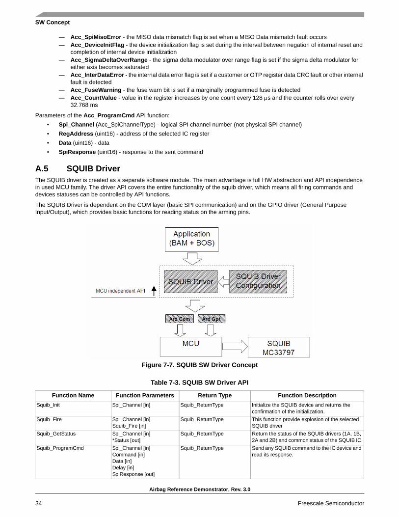
SW Concept
Airbag Reference Demonstrator, Rev. 3.0
34 Freescale Semiconductor
— Acc_SpiMisoError - the MISO data mismatch flag is set when a MISO Data mismatch fault occurs— Acc_DeviceInitFlag - the device initialization flag is set during the interval between negation of internal reset and
completion of internal device initialization— Acc_SigmaDeltaOverRange - the sigma delta modulator over range flag is set if the sigma delta modulator for
either axis becomes saturated— Acc_InterDataError - the internal data error flag is set if a customer or OTP register data CRC fault or other internal
fault is detected— Acc_FuseWarning - the fuse warn bit is set if a marginally programmed fuse is detected— Acc_CountValue - value in the register increases by one count every 128 μs and the counter rolls over every
32.768 ms
Parameters of the Acc_ProgramCmd API function:• Spi_Channel (Acc_SpiChannelType) - logical SPI channel number (not physical SPI channel)• RegAddress (uint16) - address of the selected IC register• Data (uint16) - data• SpiResponse (uint16) - response to the sent command
A.5 SQUIB DriverThe SQUIB driver is created as a separate software module. The main advantage is full HW abstraction and API independence in used MCU family. The driver API covers the entire functionality of the squib driver, which means all firing commands and devices statuses can be controlled by API functions.
The SQUIB Driver is dependent on the COM layer (basic SPI communication) and on the GPIO driver (General Purpose Input/Output), which provides basic functions for reading status on the arming pins.
Figure 7-7. SQUIB SW Driver Concept
Table 7-3. SQUIB SW Driver API
Function Name Function Parameters Return Type Function DescriptionSquib_Init Spi_Channel [in] Squib_ReturnType Initialize the SQUIB device and returns the
confirmation of the initialization.Squib_Fire Spi_Channel [in]
Squib_Fire [in]Squib_ReturnType This function provide explosion of the selected
SQUIB driverSquib_GetStatus Spi_Channel [in]
*Status [out]Squib_ReturnType Return the status of the SQUIB drivers (1A, 1B,
2A and 2B) and common status of the SQUIB IC.Squib_ProgramCmd Spi_Channel [in]
Command [in]Data [in]Delay [in]SpiResponse [out]
Squib_ReturnType Send any SQUIB command to the IC device and read its response.

SW Concept
Airbag Reference Demonstrator, Rev. 3.0
Freescale Semiconductor 35
A.6 SQUIB Parameters Detail DescriptionsBrief description of input and output API parameters is in the following paragraphs. Descriptions contains only a verbal description of the parameter. Values which each variable acquires is described in the header file SQUIB.h.
Parameters of the Squib_Init API function:• Spi_Channel (Squib_SpiChannelType) - logical SPI channel number (not physical SPI channel)
Parameters of the Squib_GetStatus API function:• Spi_Channel (Squib_SpiChannelType) - logical SPI channel number (not physical SPI channel)• Status (Squib_StatusType) output status structure containing the complete status of the ACC
— Squib_Stat1ACurrTime - firing current in 1A squib line and records the “ON” time in which the IMEAS current is above the threshold for 1A squib
— Squib_Stat1BCurrTime - firing current in 1B squib line and records the “ON” time in which the IMEAS current is above the threshold for 1B squib
— Squib_Stat2ACurrTime - firing current in 2A squib line and records the “ON” time in which the IMEAS current is above the threshold for 2A squib
— Squib_Stat2BCurrTime - firing current in 2B squib line and records the “ON” time in which the IMEAS current is above the threshold for 2B squib
— Squib_Stat1ACurrent - line 1A FET driver current limit measurement status— Squib_Stat1BCurrent - line 1B FET driver current limit measurement status— Squib_Stat2ACurrent - line 2A FET driver current limit measurement status— Squib_Stat2BCurrent - line 2B FET driver current limit measurement status— Squib_Stat1ALowSideThermalShut - 1A Low Side Squib driver thermal shutdown status— Squib_Stat1AHighSideThermalShut - 1A High Side Squib driver thermal shutdown status— Squib_Stat1BLowSideThermalShut - 1B Low Side Squib driver thermal shutdown status— Squib_Stat1BHighSideThermalShut - 1B High Side Squib driver thermal shutdown status— Squib_Stat2ALowSideThermalShut - 2A Low Side Squib driver thermal shutdown status— Squib_Stat2AHighSideThermalShut - 2A High Side Squib driver thermal shutdown status— Squib_Stat2BLowSideThermalShut - 2B Low Side Squib driver thermal shutdown status— Squib_Stat2BHighSideThermalShut - 2B High Side Squib driver thermal shutdown status— Squib_Stat1VdiagResult - firing supply voltage (VDIAG_1) diagnostics - voltage level on the VDIAG_1 pin— Squib_Stat1HSSafingSens - High Side Safing sensor diagnostics - monitors the VFIRE_XX pin connection to the
VDIAG_1 pin— Squib_Stat2VdiagResult - firing supply voltage (VDIAG_2) diagnostics - voltage level on the VDIAG_2 pin— Squib_Stat2HSSafingSens - High Side Safing sensor diagnostics - monitors the VFIRE_XX pin connection to the
VDIAG_2 pin— Squib_1AShBatt - Squib short-to-battery diagnostics - voltage level on the SENSE_1A pin— Squib_1AShGnd - Squib short-to-ground diagnostics - voltage level on the SENSE_1A pin— Squib_1BShBatt - Squib short-to-battery diagnostics - voltage level on the SENSE_1B pin— Squib_1BShGnd - Squib short-to-ground diagnostics - voltage level on the SENSE_1B pin— Squib_2AShBatt - Squib short-to-battery diagnostics - voltage level on the SENSE_2A pin— Squib_2AShGnd - Squib short-to-ground diagnostics - voltage level on the SENSE_2A pin— Squib_2BShBatt - Squib short-to-battery diagnostics - voltage level on the SENSE_2B pin— Squib_2BShGnd - Squib short-to-ground diagnostics - voltage level on the SENSE_2B pin— Squib_Stat1ALowSideCont - continuity status for the Low Side driver SQB_LO_1A connection— Squib_Stat1BLowSideCont - continuity status for the Low Side driver SQB_LO_1B connection— Squib_Stat2ALowSideCont - continuity status for the Low Side driver SQB_LO_2A connection— Squib_Stat2BLowSideCont - continuity status for the Low Side driver SQB_LO_2B connection— Squib_1AOpnShBatt - Squib 1A harness short-to-battery status with an open Squib— Squib_1AOpnShGnd - Squib 1A harness short-to-ground status with an open Squib— Squib_1BOpnShBatt - Squib 1B harness short-to-battery status with an open Squib— Squib_1BOpnShGnd - Squib 1B harness short-to-ground status with an open Squib— Squib_2AOpnShBatt - Squib 2A harness short-to-battery status with an open Squib— Squib_2AOpnShGnd - Squib 2A harness short-to-ground status with an open Squib— Squib_2BOpnShBatt - Squib 2B harness short-to-battery status with an open Squib— Squib_2BOpnShGnd - Squib 2B harness short-to-ground status with an open Squib— Squib_StatVfireBTested - reports VFIRE testing has been finished

SW Concept
Airbag Reference Demonstrator, Rev. 3.0
36 Freescale Semiconductor
— Squib_StatVfire - reports of the voltage level on the VFIRE_XX pin— Squib_StatV1diagV1 - firing supply voltage status - VDIAG_V1 voltage on the VDIAG1 pin— Squib_StatV1diagV2 - firing supply voltage status - VDIAG_V2 voltage on the VDIAG1 pin— Squib_StatV1diagV3 - firing supply voltage status - VDIAG_V3 voltage on the VDIAG1 pin— Squib_StatV1diagV4 - firing supply voltage status - VDIAG_V4 voltage on the VDIAG1 pin— Squib_StatV2diagV1 - firing supply voltage status - VDIAG_V1 voltage on the VDIAG2 pin— Squib_StatV2diagV2 - firing supply voltage status - VDIAG_V2 voltage on the VDIAG2 pin— Squib_StatV2diagV3 - firing supply voltage status - VDIAG_V3 voltage on the VDIAG2 pin— Squib_StatV2diagV4 - firing supply voltage status - VDIAG_V4 voltage on the VDIAG2 pin— Squib_StatFen1 - status of the FEN_1 arming input pin— Squib_StatFen2 - status of the FEN_2 arming input pin— Squib_StatFen1Latch - FEN1 latch status— Squib_StatFen2Latch - FEN2 latch status— Squib_StatRdiag - reports status of the R_DIAG resistor— Squib_StatRlimit1 - reports the R_LIMIT_1 resistor value - reference currents derived by the R_LIMIT_1 and
R_LIMIT_2 resistors— Squib_StatRlimit2 - reports the R_LIMIT_2 resistor value - reference currents derived by the R_LIMIT_1 and
R_LIMIT_2 resistors— Squib_DeviceType - identifier the squib IC as a four- or two-channel squib driver IC— Squib_StatVfireRtn1 - reports the resistance on the VFIRE_RTN1 pin for open pin connections— Squib_StatVfireRtn2 - reports the resistance on the VFIRE_RTN2 pin for open pin connections— Squib_Stat1AResistance - Squib 1A resistance value— Squib_Stat1BResistance - Squib 1B resistance value— Squib_Stat2AResistance - Squib 2A resistance value— Squib_Stat2BResistance - Squib 2B resistance value— Squib_Stat1ALoopsShorts - reports shorts between 1A squib lines and other firing loops— Squib_Stat1BLoopsShorts - reports shorts between 1B squib lines and other firing loops— Squib_Stat2ALoopsShorts - reports shorts between 2A squib lines and other firing loops— Squib_Stat2BLoopsShorts - reports shorts between 2B squib lines and other firing loops— Squib_Stat1ALoopsShortsAddIC - reports shorts between squib 1A loop and other loops on additional ICs— Squib_Stat1BLoopsShortsAddIC - reports shorts between squib 1B loop and other loops on additional ICs— Squib_Stat2ALoopsShortsAddIC - reports shorts between squib 2A loop and other loops on additional ICs— Squib_Stat2BLoopsShortsAddIC - reports shorts between squib 2Bloop and other loops on additional ICs
Parameters of the Squib_Fire API function:• Spi_Channel (Squib_SpiChannelType) - logical SPI channel number (not physical SPI channel)• Squib_Fire (Squib_FireType) - firing commands for squibs pairs or for separate Low/High side
Parameters of the Squib_ProgramCmd API function:• Spi_Channel (Squib_SpiChannelType) - logical SPI channel number (not physical SPI channel)• Command (Squib_ProgCmdType) - Squib command• Data (uint8) - data• Delay (uint8) - Squib diagnostic delay time• SpiResponse (uint8) - response to the sent command

Airbag Reference Demonstrator Implementation details
Airbag Reference Demonstrator, Rev. 3.0
Freescale Semiconductor 37
Appendix B Airbag Reference Demonstrator Implementation details
B.1 Airbag Reference Demonstrator Schematics
Figure 7-8. Block Schematic of the ARD Board
� �
� �
� �
� �
� �
��
��
�������������� ���
��������������� ���
��������������� ���
��������������� ���
��������������� � ��
�� �
�� �
�� �
�� �
�� �
�� �
�� �
�� �
�� �
�� �
�� �
�� �
�� �
�� �
�� �
�� �
��� ���
���� �
���� �
���� �
���� �
���
���
���
���
���
���
��� ���
�
� �
�
�
� �
�
�
� �
�
�
� �
��
�
�
� �
��
�
� �
�
�
� �
�
�
� �
�
�
� �
��
�
�
� �
��
�
� �
�
� �
���
���
���
���
�� �
�� �
���� �
���� �
���� �
���� �
����
�
� �
�
�
�
� �
�
�
���
���
���
���
��
�� �
��
�
�
��
�� �
��
�� �
��
�� �
��
�� �
��
� �
��
��
�� �
��
�� �
���
���
���
���
���
��
�� �
���
���
��
�
��
�
�� �
��
�
�� �
��
�
�� �
��
�
�� �
��
�
�� �
��
�
�� �
��
�
�� �
��
�
�� �
� �
���
��
��
��
� �
��
�
�
�
��
� �
�
� �
��
��
��
��
� �
�
��
��
� !
"#$
%&�#
'()*
�#+
)�
,-./
)$'&�
./0)
�
)1
�!'
)*�
2))'
,3
�!%
)&�#
'()*
��
�&�
(!44
#3#-!
'#,$*
5��
*5�
��
*�
�
�*
��
�6�
��
��
&��
5*&�
�56
��
��
��
������&����
& ����
�
�.)4
7!89
&�-'
,0)
&�:9
&�::
�
���
��
&����;
�
:�
��
!"
#$%&
�#'()
*
�#+
)�
,-./
)$'&�
./0)
�
)1
�!'
)*�
2))'
,3
�!%
)&�#
'()*
��
�&�
(!44
#3#-!
'#,$*
5��
*5�
��
*�
�
�*
��
�6�
��
��
&��
5*&�
�56
��
��
��
������&����
& ����
�
�.)4
7!89
&�-'
,0)
&�:9
&�::
�
���
��
&����;
�
:�
��
!"
#$%&
�#'()
*
�#+
)�
,-./
)$'&�
./0)
�
)1
�!'
)*�
2))'
,3
�!%
)&�#
'()*
��
�&�
(!44
#3#-!
'#,$*
5��
*5�
��
*�
�
�*
��
�6�
��
��
&��
5*&�
�56
��
��
��
������&����
& ����
�
�.)4
7!89
&�-'
,0)
&�:9
&�::
�
���
��
&����;
�
:�
�
�<
��
� ���
��� ��
��
�
��
=
��
��
�
���
� �
��
��
�
��
�� �
��
��
��
��
�
��
�
��
�
��
�
��
�
��
�
��
�
��
�
�� �
�� �
�� �
�� �
�� �
�� �
�� �
�� �
���
��
��
��
��
��
���
���
���
���
���
��
���� �
���� �
���� �
���� �
��� ���
���
��� ���
�� �
�� �
�� �
�� �
�� �
�� �
�� �
�� �
�� �
�� �
�� �
�� �
�� �
�� �
�� �
�� �
���
�� �
�� �
���
���
���
���
���
����
���� �
���� �
���� �
���� �
��
�&>
&��
���
�&
�
��
���
��
���
�
���
�
�
�
��
��
�
�
��
��
�
�
���
��
���
��
�
� �
�
�
� �
�
�
��
��
��
�
��� �� ���
���
� �
��
��
�
��
�� �
��
��
�=
��
��
�
��
=
���
��
�
��
��
��
�
�
� �
��
�
�
� �
��
�
� �
�
�
� �
�
�
���
��
��
�
�
���
�
�
�
��
��
�
�
��
��
�
�
��
���
�� �
��
�
��
��
��
�
��
� �
���>
� �
��
�=
��
��
�� �
��
�� �
��
�� �
��
�� �
��
� �
��
���
���
��
�
��
���
���
���
���
��
�� �
���
���
��
�
��
�
���
���
���
���
���
��
�� �
��
�� �
��
�� �
��
�
�
���
��
��
��
�
�
�
� �
��
�
�
� �
�
�
� �
�
�
� �
���
�
� �
�
�
� �
�
� �
��
��� ��
����
�
� �
�
�

Airbag Reference Demonstrator Implementation details
Airbag Reference Demonstrator, Rev. 3.0
38 Freescale Semiconductor
Figure 7-9. ARD Board - MCU + Central Accelerometer
� �
� �
� �
� �
� �
��
��
��
��
����
�
����
���
����
����
� ��
����
�
�!�
��"�
���!
"!��
�! !
�
��
��
�
��
�
��
��
�
�
��
�
�
�
��
��
��
��
�
��
� �
��
�
���
��
�
� �
�
���
�
�
�
���
� �
���
��
�
� �
�
��
��
�
�
��
��
� �
�
��
� �
�
��
��
��
��
��
��
�=
��
���
��
�
�
� �
�
�
� �
��
�
� �
��
�
�
� �
�
�
���
��
��
��
� �
�
��
�
��
�
��
�
��
�
��
�
�
��
� �
�
��
� �
�
��
�
���
�
�
��
��
�
�
��
��
�
�
��
�
��
�
��
=
��
� �
�
��
=
���
�
� �
��
�
��
��
�
� �
��
�
� �
�
�
��
���
��
�
��
��
� �
��
��
��
�
��
��
��
�
��� ��
���
�
�
�
��
��
�
�
��
�
�
�
��
�
�
��� ��
��
� �
��
��
��
���
�
��
��
��
��
� �
�
�=
��
��
��
��
��
���
��
���
��
��
��
��
��
��
��
��
��
��
��
��
��
� �
�
��
��
��
��
��
��
��
��
�
� �
��
�
��
��
�
��
�
��
�
��
�
��
�
��
=
�
��
��
��
�
��
�
���
� �
��
��
�
��
�� �
��
� �
�
�=
��
���
��
��
��
��
���
�
�
�
��
��
�
�
��
��
�
�
��
�
��
�
���
��
���
��
�
� �
�
�
� �
�
�
� �
��
�
�
� �
��
�
� �
�
�
� �
�
�
���
��
��
��
�
��
=
� !
"#$
%&�#
'()*
�#+
)�
,-./
)$'&�
./0)
�
)1
�!'
)*�
2))'
,3
�!%
)&�#
'()*
��
�&�
(!44
#3#-!
'#,$*
5��
*5�
��
*�
�
�*
��
�6�
��
��
&��
5*&�
�56
��
��
��
������&����
& ����
�
�.)4
7!89
&�-'
,0)
&�:9
&�::
�
;��
&�&������
&�������
�� �
�
��
!"
#$%&
�#'()
*
�#+
)�
,-./
)$'&�
./0)
�
)1
�!'
)*�
2))'
,3
�!%
)&�#
'()*
��
�&�
(!44
#3#-!
'#,$*
5��
*5�
��
*�
�
�*
��
�6�
��
��
&��
5*&�
�56
��
��
��
������&����
& ����
�
�.)4
7!89
&�-'
,0)
&�:9
&�::
�
;��
&�&������
&�������
�� �
�
��
!"
#$%&
�#'()
*
�#+
)�
,-./
)$'&�
./0)
�
)1
�!'
)*�
2))'
,3
�!%
)&�#
'()*
��
�&�
(!44
#3#-!
'#,$*
5��
*5�
��
*�
�
�*
��
�6�
��
��
&��
5*&�
�56
��
��
��
������&����
& ����
�
�.)4
7!89
&�-'
,0)
&�:9
&�::
�
;��
&�&������
&�������
�� �
�
�
?��
��
�&�
��
?��
��
�&�
��
��
���
�
���
�:�
���
�:�
���
�:�
���
�:�
���
��5
���
��5
���
:@��
5�
��:@
��5
���
���
��A�
��
���
����
A���
�
�
�=
��
�
�
�
�=
��
��
��
��
�
��
��
�:�
���
�:�
���
�@��
���
�@��
���
:@��
�5
���
:@��
�5
���
�:�
���
�:�
���
:@��
�5
���
:@��
�5
���
=�
���
��
��=
���
��
��
���
�:�
���
�:�
���
�:�
���
�:�
��:
�@��
��:
�@��
���
�:�
���
�:�
���
:@��
5�
��:@
��5
���
��
��
:�<
��
���
��
��
:�<
��
��
��
�
��
���
��
=�
��
��
�
��
�B�
��
��
��
�
��
��
���:
����
��
���
��
�
��
��
��
�
��
��
����
��
��
��
��
���
��
����
���
��5
���
��5
���
���
A�
����
�A
��
�
���
�@:�
���
�@:�
���
:@��
5�
��:@
��5
���
:@��
�5
���
:@��
�5
���
���
��A�
��
���
����
A���
�
�
�=
��
�
�
�
�=
��
��
��
��
�
�
���
:@��
5�
��:@
��5
���
�@��
���
�@��
���
��
��
���
��
��
��:
:@��
5�
�::@
��5
���
��
����
��
���
��
���
���
���
��
��� �
:
��
�
���
�
���
�
���
�
���
�
���
�
���
�
���
�
:��
�
���
�
���
�
���
�
��:
�
���
�
���
�
���
��
:B�
��<
�:
��
�B��
<��
��
���
��
���
��
�B�
���
��
��
�B�
��
��
��
�B�
��
��
��
�B�
���
�B�
���
����
�?�
B��
?�B�
��
�
�B�
�
:B�
��
�
:��
�?�
B��
?�B�
��
�
�B�
��:
B��
�
�:
��
��
�
�:B
��
:��
���
�
:B��
���
���
�:B
��
�
�:B
��
�
��B
��
���
��
:B��
�
�:B
���
�
�B��
���
��
��:
B��
�
��B
��
�
�:B
��
�
��B
��
���
��
�:B
���
�
�B��
�
�:B
���
�
�B��
��:
���
���
:B�
���
�B�
��
:B�
��
:B�
�:
�
���
���
�B�
��
��B�
��
�B�
��
�B�
��
�
���
���
�B�
��
�B�
��
�B�
��
�B�
��
�
���
���
�B�
��B
���
�B�
��
�B�
��
�
���
���
�B�
���
�B�
��
�B�
��
�B�
��
�:
���
���
�B�
��
��B�
��
�B�
��
�B�
��
��
���
���
�B�
��
�B�
��
�B�
��
�B�
��
��
��
�:B
��
:��
���
:B�
��
��
��
��B
��
���
���
�B�
��
��
���
:B�
�:�
���
�B�
���
���
�B�
���
���
�B�
���
���
�B�
����
��
��
�
�B��
��B
���
��
���
�B�
����
���
�B�
����
�
�::
B�
::��
�
�:�
B�
:���
�
�:�
B�
:���
�
�:�
B�
:���
�
�:�
B�
:���
�
�:�
B�
:���
�
�:�
B�
:���
�
�:�
B�
:���
�����
������
���5�
��������
������
�������
�������
����:
�����
�����:
�����:
������
������
��������
�������
�������
��
��
B�
��
��
��
��
��:
��
��
��
��
���
���
���
���
:@��
5�
��:@
��5
���
:@��
5�
��:@
��5
?���
��
� �
��
?���
��
� �
��
� � � � � �
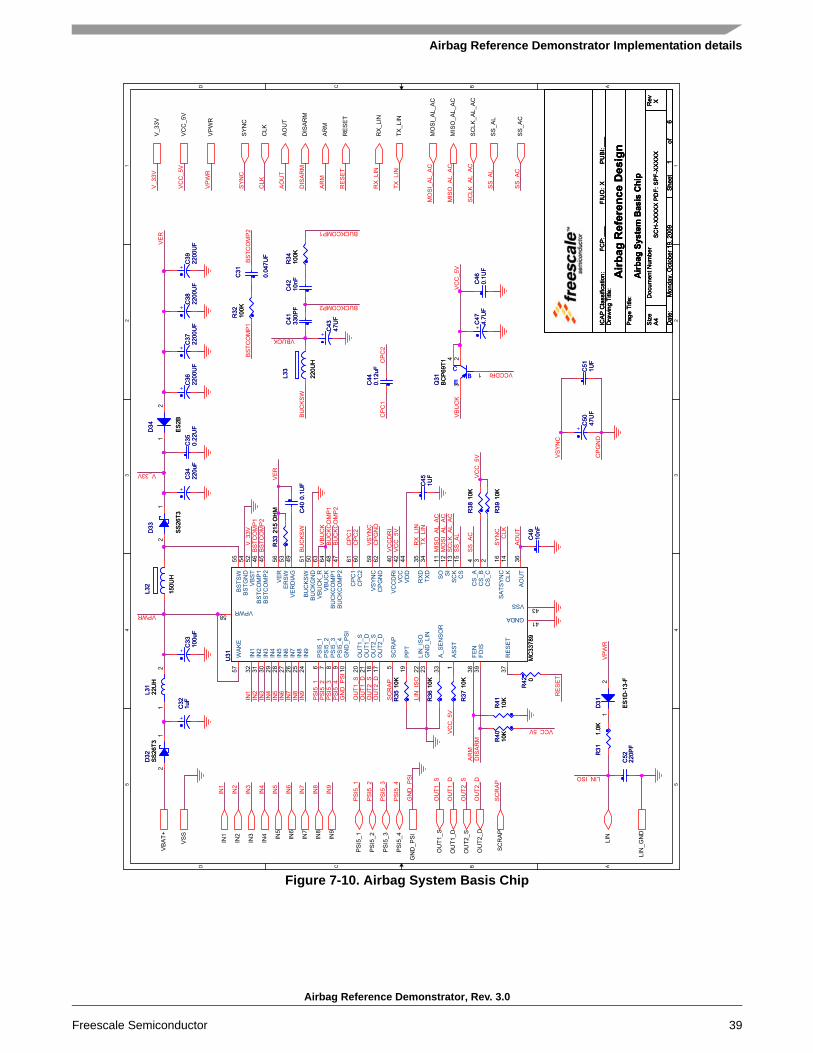
Airbag Reference Demonstrator Implementation details
Airbag Reference Demonstrator, Rev. 3.0
Freescale Semiconductor 39
Figure 7-10. Airbag System Basis Chip
� �
� �
� �
� �
� �
��
��
��
�
� �
��
� ���
�
��
��
�
��
���
��
�
��
���
��
�
��
��
��������
��������
��
�
�
����
��
�
����
��
�
����
��
�
����
��
��
��
��
��
��
��
��
��
�
��
�
������
��
��
��
��
� �
�
��
���
�� �
��
���
�
�
��
��
�
�
��
���
�
�
��
�
��
��
�
�
���
�
�
�
��
�
��
��
�
�
��
�
��
� �
�
��
=�
��
��
��
�=
��
��
��
�
�� �
��
��
���
���
��
�
�=
��
���
�
��
��
��
�
��
� �
��
��
�� �
��
�� �
��
�� �
��
� �
�
��
��
�
��
���
���
��
���
��
�
���
���
���
��
�� �
��
�� �
��
�� �
��
�� �
����
����
��
� �
��
��
� �
��
���
��
=�
�
���
���
���
���
���
���
���
��
�� �
���
���
���
���
���
��
�� �
��
�� �
��
�� �
��
�� �
��
�� �
��
�
�
��
�� �
��
�� �
��
�� �
��
�
�
��
� �
�
���
��
�
��
�
��
� �
�
��
��
�
��� ��
���
��
��� ���
��
��
��
���
�� �
��
�
��
��
��
�
�
�>
� �
��
�=
��
��
�� �
��
�� �
��
�� �
��
�� � ���
���
���
���
���
��
��
��
��
���
���
��
�
��
���
�
�
�
��
��
�
�
��
��
�
�
��
�
��
�
��
� �
��
��
�� ����
���
���
���
���
��
�� �
��
�� �
��
�� �
��
�
�
���
��
��
��
� !
"#$
%&�#
'()*
�#+
)�
,-./
)$'&�
./0)
�
)1
�!'
)*�
2))'
,3
�!%
)&�#
'()*
��
�&�
(!44
#3#-!
'#,$*
5��
*5�
��
*�
�
�*
��
�6�
��
��
&��
5*&�
�56
��
��
��
������&����
& ����
�
�,$
7!89
&�-'
,0)
&��9
&�::
�
����
��&�����
&�����
&���
C
��
��
!"
#$%&
�#'()
*
�#+
)�
,-./
)$'&�
./0)
�
)1
�!'
)*�
2))'
,3
�!%
)&�#
'()*
��
�&�
(!44
#3#-!
'#,$*
5��
*5�
��
*�
�
�*
��
�6�
��
��
&��
5*&�
�56
��
��
��
������&����
& ����
�
�,$
7!89
&�-'
,0)
&��9
&�::
�
����
��&�����
&�����
&���
C
��
��
!"
#$%&
�#'()
*
�#+
)�
,-./
)$'&�
./0)
�
)1
�!'
)*�
2))'
,3
�!%
)&�#
'()*
��
�&�
(!44
#3#-!
'#,$*
5��
*5�
��
*�
�
�*
��
�6�
��
��
&��
5*&�
�56
��
��
��
������&����
& ����
�
�,$
7!89
&�-'
,0)
&��9
&�::
�
����
��&�����
&�����
&���
C
��
�
�
�
<��
�
���
��
�
�
<��
�
���
��
�
���
���
�:�
���
�:�
#�
����
:.5
#�
����
:.5
���
��5
���
��5
���
��
����
���
��
����
��
#�
���.
5#
���
�.5
��:
�:�
��:
�:�
#���
�@��
5#�
���@
��5
���
:@��
�5
���
:@��
�5
# ���
��::
�5
# ���
��::
�5
���
�@:�
���
�@:�
���
�:$5
���
�:$5
���
�:$5
���
�:$5
���
��:�
�
���
��:�
�
���
�::�
���
�::�
��� :
��� :
���
��:�
5�
����
:�5
���
��:�
�
���
��:�
�# �
����
::�
5
# ���
��::
�5
���
��:�
5�
����
:�5
# ���
�::.
5
# ���
�::.
5
# ��:
���
5
# ��:
���
5
���
�:�
���
�:�
���
���
���
���
��
��
���
�:�
���
�:�
���
�:�
���
�:�
���
:@:�
��5
���
:@:�
��5
# ���
���
5
# ���
���
5
���
���&
���
���
���&
���
���
��5
���
��5
���
�::�
���
�::�
���
��
�
���
��
�
��
���
��
����
�
���
��
����
�
�
��
�
��
��
��
�
��
�
��
�
��
��
�� �
�
��
�� �
�
��
�� �
�
��
�� �
�
��
� �
��
�:
��
��
��
��
��
���
���
��
��
��
�
��=
��
��
��
�� �
���
���
���
��
���
��
�� �
�:
��
�� �
��
���
��
���
��
� �
����
���
����
���
���
����
���
���
����
���
���
�:��
���
���
��
�
��
��
���
���
���
��
��
�
��
���
��
��
��
5��
��
5���
��
��
��
��
�:
�����
��
���
�����
��
���
�
����
��
��
���
��
��
��
�
��
���
��
��
��
��
��
��
��
��
��
��
��
�
��
��
��:
�
��
��
��
�
��
��
��
��
��
�
���
���
�
���
��
��
���
�
��
��
������
��
=�
���
��
��
�:�
��
���
��
��
���
�
��
� �
��
�
��
���
���
:@��
.5�
��:@
��.5
���
��
��6�
�65
���
��
��6�
�65�
�
���
�:�
���
�:�
# ���
��::
�5
# ���
��::
�5
���
��
����
���
��
����
��
���
:@��
5�
��:@
��5
��:
:@��
5�
�::@
��5
# ���
��::
�5
# ���
��::
�5
���
�:�
���
�:�

Airbag Reference Demonstrator Implementation details
Airbag Reference Demonstrator, Rev. 3.0
40 Freescale Semiconductor
Figure 7-11. Squibs
� �
� �
� �
� �
� �
��
��
��
� �
�
� �
��
��
��
�
��
��
��
��
�
��
�� �
���
� �
���
� �
��
��
��
���
��
� �
�
���
� �
��
��
��
���
��
� �
�
��
��
�
��
��
��
��
��
�
��
=
��
��
�
��
=
��
��
�
� �
��
� �
��
� �
��
��
�
��
�
�� �
�� �
�� �
�� �
��
�
��
���
�
��
��
� �
�� �
�� �
�� �
�� �
�� �
��
�
��
�
�� �
��
�
��
�
�� �
�� �
�� �
��
�
��
�
�� �
�� �
�� �
��
���
�
�� �
��
���
�
�� �
�� �
��
�
��
�
�� �
�� �
��
� �
�
� �
��
��
� �
�
� �
��
��
��
�
���
� �
��
�� �
��
�
��
� �
�
��
�
��
�
��
�
��
�
��
�
��
�
��
�
��
�
��
=
��
��
�
��
��
�� �
�� �
�� �
�� �
�� �
�� �
�� �
�� �
��
�
��
��
��
� !
"#$
%&�#
'()*
�#+
)�
,-./
)$'&�
./0)
�
)1
�!'
)*�
2))'
,3
�!%
)&�#
'()*
��
�&�
(!44
#3#-!
'#,$*
5��
*5�
��
*�
�
�*
��
�6�
��
��
&��
5*&�
�56
��
��
��
������&����
& ����
�
�,$
7!89
&.%
.4'&�
�9&�
::�
�D ��
��
��
!"
#$%&
�#'()
*
�#+
)�
,-./
)$'&�
./0)
�
)1
�!'
)*�
2))'
,3
�!%
)&�#
'()*
��
�&�
(!44
#3#-!
'#,$*
5��
*5�
��
*�
�
�*
��
�6�
��
��
&��
5*&�
�56
��
��
��
������&����
& ����
�
�,$
7!89
&.%
.4'&�
�9&�
::�
�D ��
��
��
!"
#$%&
�#'()
*
�#+
)�
,-./
)$'&�
./0)
�
)1
�!'
)*�
2))'
,3
�!%
)&�#
'()*
��
�&�
(!44
#3#-!
'#,$*
5��
*5�
��
*�
�
�*
��
�6�
��
��
&��
5*&�
�56
��
��
��
������&����
& ����
�
�,$
7!89
&.%
.4'&�
�9&�
::�
�D ��
��
�
���
�:�
���
�:�
���
:@��
5�
��:@
��5
���
:@��
5�
��:@
��5
���
:@��
5�
��:@
��5
���
:@��
5�
��:@
��5
���
�:�
���
�:�
���
�:�
���
�:�
���
��
����
���
���
��
����
���
�<
�
� �
�
�<
�
� �
�
��
��
��
����
���
��
����:
�5�
��
�
���
<
��
���
��
��
� �
�
��
��
�
���
�
�5�
��
�
�
5��
���
� �
����
���
��
��
� �
��
�<
�
� �
��
�<
�
� �
��
��
��
� �
��
� �
����
���
5��
��:
�<
�
� �
���
5��
� �
��
� �
��
��
�5�
��
���
��
�5�
��
���
��
��
��
���
�5�
��
�
���
<
��
���
��
���
��
�:
��
��
� �
��
�<
�
� �
��
���
:@��
5�
��:@
��5
���
��
����
���
���
��
����
���
�<
�
� �
�
�<
�
� �
�
��
��
��
����
���
��
����:
�5�
��
�
���
<
��
���
��
��
� �
�
��
��
�
���
�
�5�
��
�
�
5��
���
� �
����
���
��
��
� �
��
�<
�
� �
��
�<
�
� �
��
��
��
� �
��
� �
����
���
5��
��:
�<
�
� �
���
5��
� �
��
� �
��
��
�5�
��
���
��
�5�
��
���
��
��
��
���
�5�
��
�
���
<
��
���
��
���
��
�:
��
��
� �
��
�<
�
� �
��
���
�:�
���
�:�
���
�:�
���
�:�
���
:@��
5�
��:@
��5
���
�:�
���
�:�

Airbag Reference Demonstrator Implementation details
Airbag Reference Demonstrator, Rev. 3.0
Freescale Semiconductor 41
Figure 7-12. Main Automotive Connector
� �
� �
� �
� �
� �
��
��
���
���
���
���
�
�
���
���
��
�
�
� �
�
� �
���
���
���
���
���
�
�
���
���
���
���
���
���
���
���
���
��
��
� �
��
��
� �
�� �
�� �
�� �
�� �
��
��
� �
��
��
� �
�� �
�� �
�� �
�� �
�
� �
�
� �
���
��
���
�
��
�� �
��
�� �
��
�
��
���
��
���
�
��
�� �
��
�� �
��
�� �
��
�� �
��
�
�� �
��
�
�� �
��
�
�� �
��
�
��
�
�� �
��
�
�� �
��
�
�� �
��
�
�� �
�� �
��
�
�
���
���
���
���
�
�
��
�� �
��
�� �
��
�� �
��
�� �
���
���
��
�
��
�
��
� �
��
��
�
��
�
��
�
��
�
��
�
��
�
��
�
��
�
�� �
�� �
�� �
�� �
�� �
�� �
�� �
�� �
�
� �
�
� �
���
���
���
���
���
��
�
��
���
�
��
�� �
��
�� �
��
�� �
� !
"#$
%&�#
'()*
�#+
)�
,-./
)$'&�
./0)
�
)1
�!'
)*�
2))'
,3
�!%
)&�#
'()*
��
�&�
(!44
#3#-!
'#,$*
5��
*5�
��
*�
�
�*
��
�6�
��
��
&��
5*&�
�56
��
��
��
������&����
& ����
�
�)7
$)47
!89&�
-',0
) &�
�9&�
::�
���
�����
��
��
!"
#$%&
�#'()
*
�#+
)�
,-./
)$'&�
./0)
�
)1
�!'
)*�
2))'
,3
�!%
)&�#
'()*
��
�&�
(!44
#3#-!
'#,$*
5��
*5�
��
*�
�
�*
��
�6�
��
��
&��
5*&�
�56
��
��
��
������&����
& ����
�
�)7
$)47
!89&�
-',0
) &�
�9&�
::�
���
�����
��
��
!"
#$%&
�#'()
*
�#+
)�
,-./
)$'&�
./0)
�
)1
�!'
)*�
2))'
,3
�!%
)&�#
'()*
��
�&�
(!44
#3#-!
'#,$*
5��
*5�
��
*�
�
�*
��
�6�
��
��
&��
5*&�
�56
��
��
��
������&����
& ����
�
�)7
$)47
!89&�
-',0
) &�
�9&�
::�
���
�����
��
�
���
:@:�
��5
���
:@:�
��5
���
�@�
���
�@�
���
�:$5
���
�:$5
��:
�:@
��5
��:
�:@
��5
���
�@�
���
�@�
���
:@:�
��5
���
:@:�
��5
���
:@��
5�
��:@
��5
���
�:@
��5
���
�:@
��5
���
�@�
���
�@�
���
�:$5
���
�:$5
���
::@
��5
���
::@
��5
��:
�:@
��5
��:
�:@
��5
?��
��
� �
���
?��
��
� �
���
��
�� �
� ��
��:
����
����
����
����
���:
����
����
����
����
���:
����
����
����
����
���:
����
����
����
����
���:
����
����
����
���
�:@
��5
���
�:@
��5
���
:@:�
��5
���
:@:�
��5
��:
�:@
��5
��:
�:@
��5
��:
�:@
��5
��:
�:@
��5
���
:@:�
��5
���
:@:�
��5
���
�:@
��5
���
�:@
��5
���
�:$5
���
�:$5
���
�:$5
���
�:$5
���
�:@
��5
���
�:@
��5
��:
�:@
��5
��:
�:@
��5
��:
::@
��5
��:
::@
��5
���
:@:�
��5
���
:@:�
��5
���
�:@
��5
���
�:@
��5
���
�:@
��5
���
�:@
��5
���
�:$5
���
�:$5
��:
�:@
��5
��:
�:@
��5
���
�:$5
���
�:$5
���
:@:�
��5
���
:@:�
��5
���
�:@
��5
���
�:@
��5
��:
�:@
��5
��:
�:@
��5
���
�:@
��5
���
�:@
��5
���
:@:�
��5
���
:@:�
��5
���
:@��
5�
��:@
��5
���
:@:�
��5
���
:@:�
��5
��:
�:$5
��:
�:$5
��:
�:@
��5
��:
�:@
��5
���
�@�
���
�@�
���
�:$5
���
�:$5
��:
�:@
��5
��:
�:@
��5
���
�:$5
���
�:$5

Airbag Reference Demonstrator Implementation details
Airbag Reference Demonstrator, Rev. 3.0
42 Freescale Semiconductor
B.2 ARD Placement and Layout
Figure 7-13. Top View and Placement

Airbag Reference Demonstrator Implementation details
Airbag Reference Demonstrator, Rev. 3.0
Freescale Semiconductor 43
Figure 7-14. Bottom View
B.3 Bill of MaterialsTable 7-4. Bill of Materials
Item Number Quantity Part Reference Value Description
1 34
C11,C12,C14,C16,C21,C22,C46,C61,C64, C72,C73,C74,C98,C99,C100,C101,C102, C103,C104,C105,C106,C107,C108,C109, C110,C111,C112,C113,C114,C115,C116, C117,C118
0.1 μF CAP CER 0.10UF 25V 10% X7R 0603
2 3 C13,C15,C17 0.22 μF CAP CER 0.22UF 16V 10% X7R 06033 4 C18,C19,C45,C51 1.0 μF CAP CER 1.0UF 25V 10% X5R 06034 9 C31,C81,C82,C83,C84,C85,C86,C87,C88 0.047 μF CAP CER 0.047UF 50V 10% X7R 06035 1 C32 1.0 μF CAP ALEL 1.0UF 50V 20% - SMT6 1 C33 100 μF CAP ALEL 100UF 25V 20% - SMT7 1 C34 220 μF CAP ALEL 100UF 50V 20% - RADIAL TH8 1 C35 0.22 μF CAP CER 0.22UF 50V 5% X7R 12069 4 C36,C37,C38,C39 2200 μF CAP ALEL 2200UF 35V +30/0% - RADIAL
10 5 C40,C62,C63,C65,C66 0.1 μF CAP CER 0.1UF 50V 5% X7R 080511 1 C41 330 pF CAP CER 330PF 50V 5% C0G 0603
12 11 C42,C49,C89,C90,C91,C92,C93,C94,C95, C96,C97 10 nF CAP CER 0.01UF 50V 5% X7R 00603
13 1 C43 47 μF CAP TANT 47UF 16V 10% - 6032-2814 1 C44 -0.12 μF CAP CER 0.12UF 50V 10% X7R 0603

Airbag Reference Demonstrator Implementation details
Airbag Reference Demonstrator, Rev. 3.0
44 Freescale Semiconductor
15 1 C47 4.7 μF CAP TANT 4.7UF 10V 10% - 3216-1816 1 C50 47 μF CAP TANT 47UF 25V 10% - 734317 3 C52,C75,C77 220 pF CAP CER 220PF 50V 10% X7R 060318 1 C71 2.2 μF CAP CER 2.2UF 25V 10% X7R 080519 1 C76 2200 pF CAP CER 2200PF 50V 5% X7R 060320 1 D11 RED LED RED SGL 2MA 0805 SMT21 1 D12 YELLOW LED YEL SGL 2MA 0805 SMT22 1 D31 ES1D-13-F DIODE RECT 1A 200V SMA SMT23 2 D32,D33 SS26T3 DIODE SCH PWR 2A 60V SMB24 1 D34 ES2B DIODE RECT ULTRA FAST 2A 100V DO-214AA25 1 J11 HDR 2X3 HDR 2X3 TH 2.54MM CTR 340H AU26 1 J81 CON_2X28 CON 2X28 ASM RA TH 3MM SP 30.7MM - 118L27 1 JP11 HDR_1X6 HDR 1X6 TH 100MIL SP 408H AU28 1 L31 22UH IND PWR 22UH@100KHZ 2.25A 20% SMT29 1 L32 150UH IND PWR 150UH@100KHZ 1.35A 20% SMT30 1 L33 220UH IND PWR 220UH@100KHZ 1.15A 20% SMT31 1 Q31 BCP69T1 TRAN PNP AUD 1A 20V SOT22332 1 R11 3.3K RES MF 3.30K 1/10W 1% 0603
33 20R12,R13,R14,R15,R16,R17,R18,R35,R36, R37,R38,R39,R40,R41,R61,R62,R63,R64, R65,R66
10K RES TF 10K 1/10W 5% RC0603
34 2 R19,R20 1.6K RES MF 1.6K 1/10W 1% 060335 1 R21 1.0M RES MF 1.0M 1/10W 1% 060336 1 R31 1.0K RES MF 100K 1/4W 1% 120637 2 R32,R34 100K RES TF 100K 1/10W 1% 060338 1 R33 215 OHM RES MF 215 OHM 1/2W 1% 201039 1 R42 0 RES MF ZERO OHM 1/10W 060340 2 R71,R72 60.4 RES MF 60.4 OHM 1/8W 1% 080541 4 R81,R82,R83,R84 3.3 RES MF 3.30 OHM 1/8W 1% 0805
42 1 U11 MCc9S12XEG128 IC MCU 16BIT 128K FLASH 12K RAM 50MHZ 5.5V QFP80
43 1 U12 MMA6801QR244 2 U13,U14 NL27WZ32 IC GATE OR DUAL 2-INPUT 1.65-5.5V US845 1 U31 MC33789 IC CTRL AIRBAG 5.2-20V LQFP64EP
46 2 U61,U62 MC33789EK IC SQUIB DRV AIRBAG FOUR CHANNEL 5V SOICW32
47 1 U71 CAN Phy IC HS CAN XCVR 5V SOIC1448 1 X11 4MHZ XTAL 4MHZ RSN 6V SMT
Freescale does not assume liability, endorse, or warrant components from external manufacturers that are referenced in circuit drawings or tables. While Freescale offers component recommendations in this configuration, it is the customer’s responsibility to validate their application.
Table 7-4. Bill of Materials
Item Number Quantity Part Reference Value Description

Acronyms
Airbag Reference Demonstrator, Rev. 3.0
Freescale Semiconductor 45
Appendix C AcronymsACC Central AccelerometerADC Analog To Digital ConverterAPI Application Protocol InterfaceARD Airbag Reference DemonstratorASBC Airbag System Basis ChipBAM Boot Assist ModuleBOS Basic Operation SystemCAN Controller Area NetworkCOM Serial Communication PortECU Electronic Control UnitEEPROM Electrically Erasable Programmable Read-Only MemoryGUI Graphical User InterfaceGPT General Purpose TimerGPO General Purpose OutputLIN Local Interconnect NetworkMUX MultiplexerN/A Not ApplicablePCB Printed Circuit BoardPSI5 Peripheral Sensor Interface 5SPI Serial Peripheral InterfaceSW SoftwareSQUIB Automobile AirBagVREG Voltage RegulatorWD Watchdog

Document Number: ARDRMRev 3.04/2012
Information in this document is provided solely to enable system and software
implementers to use Freescale products. There are no express or implied copyright
licenses granted hereunder to design or fabricate any integrated circuits on the
information in this document.
Freescale reserves the right to make changes without further notice to any products
herein. Freescale makes no warranty, representation, or guarantee regarding the
suitability of its products for any particular purpose, nor does Freescale assume any
liability arising out of the application or use of any product or circuit, and specifically
disclaims any and all liability, including without limitation consequential or incidental
damages. “Typical” parameters that may be provided in Freescale data sheets and/or
specifications can and do vary in different applications, and actual performance may
vary over time. All operating parameters, including “typicals,” must be validated for
each customer application by customer’s technical experts. Freescale does not convey
any license under its patent rights nor the rights of others. Freescale sells products
pursuant to standard terms and conditions of sale, which can be found at the following
address: http://www.reg.net/v2/webservices/Freescale/Docs/TermsandConditions.htm
Freescale, the Freescale logo, AltiVec, C-5, CodeTest, CodeWarrior, ColdFire, C-Ware,
Energy Efficient Solutions logo, mobileGT, PowerQUICC, SafeAssure, QorIQ, Qorivva,
StarCore, and Symphony are trademarks of Freescale Semiconductor, Inc., Reg. U.S.
Pat. & Tm. Off. Airfast, BeeKit, BeeStack, ColdFire+, CoreNet, Flexis, MagniV, MXC,
Platform in a Package, Processor expert, QorIQ Qonverge, QUICC Engine, Ready Play,
SMARTMOS, TurboLink, Vybrid, and Xtrinsic are trademarks of Freescale
Semiconductor, Inc. All other product or service names are the property of their
respective owners.
© 2012 Freescale Semiconductor, Inc.
How to Reach Us:Home Page: freescale.com
Web Support: freescale.com/support