mbs hd range air suspension for fuwa k … · mbs hd range air suspension for fuwa k-hitch...
TRANSCRIPT
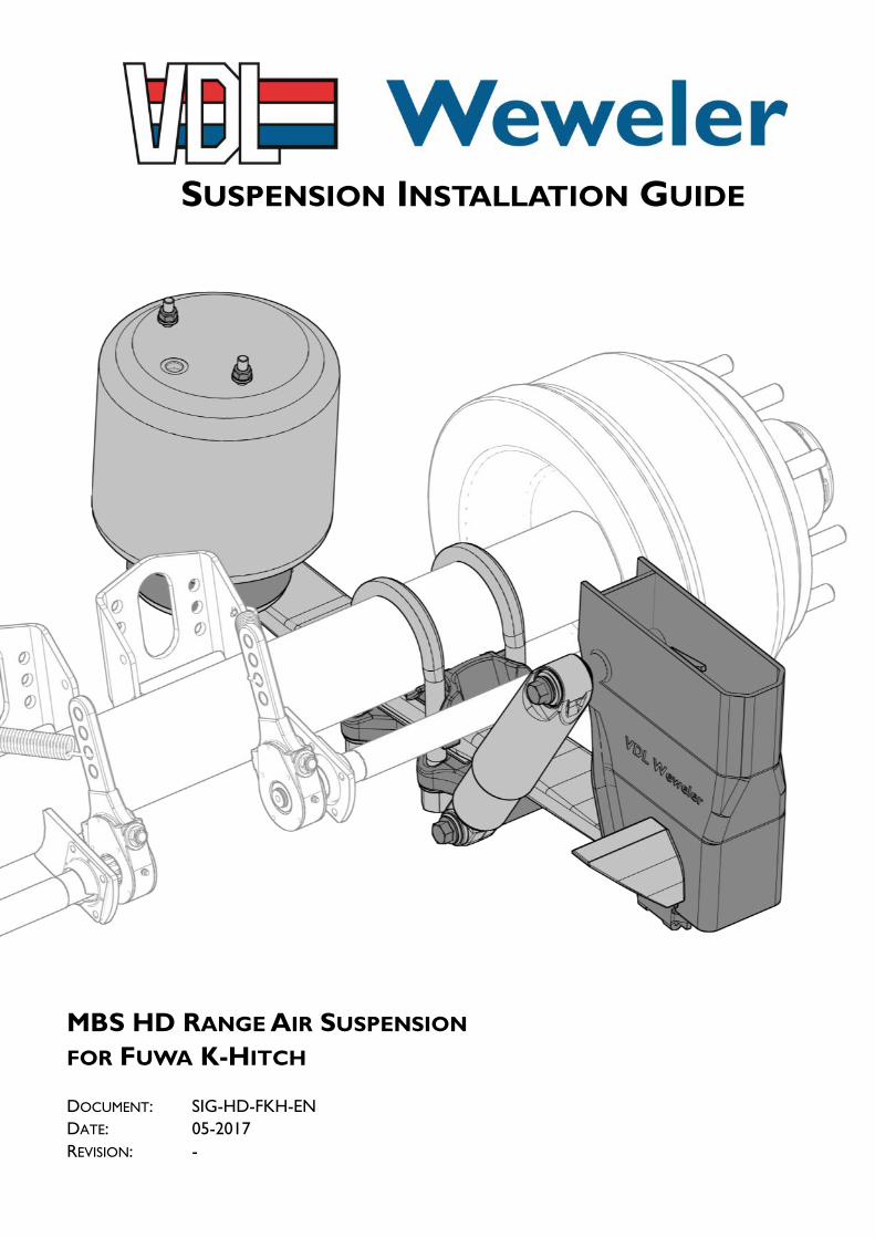
MBS HD RANGE AIR SUSPENSION
FOR FUWA K-HITCH
DOCUMENT: SIG-HD-FKH-EN
DATE: 05-2017
REVISION: -
SUSPENSION INSTALLATION GUIDE
2 SIG-HD-FKH-EN
Contact Details
For additional information contact VDL Weweler b.v.
P.O. Box 142, 7300 AC Apeldoorn
Ecofactorij 10, 7325 WC Apeldoorn
The Netherlands
General:
Tel: +31 (0)55 538 51 00
Fax: +31 (0)55 538 51 93
Email: [email protected]
Website: www.vdlweweler.nl
Aftersales / warranty:
Tel: +31 (0)55 538 51 68
Fax: +31 (0)55 538 51 05
Email: [email protected]
Copyright © 2017
Date Revision Comment Author
May 2017 - Initial version RTS
Revision summary
3 SIG-HD-FKH-EN
Contents
General notes…………………………………………………………………………………………...………………………..
Welding remarks…………………………………………………………………………………………………………………
Warranty and liability……………………………………………………………………………………………………….……
Pictograms & symbols……………………………………………………………………………………………………………
Explanation MBS-HD Air suspension system coding...……………………………………………………………………..……
Technical specifications / design information…...……………………………………………………………………..…………
Hanger brackets & pedestals………………………………………………………………………………………………..……
3.1 Dimensions of hanger bracket & pedestal…………………………………………………………………...………
3.2 Alignment of hanger bracket ...……………………………………………………………………………………...
3.3 Welding of hanger bracket...………………………………………………………………………………………...
3.4 Welding of pedestal..………………………………………………………………………………………………...
3.5 Welding of plate for hanger bracket bracing….…………………………………………………………………….
3.6 Welding of casting for hanger bracket bracing….…………………………………………………………………...
3.7 Welding of wear plates after alignment…...….……………………………………………………………………...
Axle seats………………………………………………………………………………………………………………………...
4.1 Welding of standard axle seats for round axles……...……………………………………………………………...
4.2 Welding of HD axle seats for round axles………………………………………………………………………….
4.2 Welding of HD axle seats for square 150 axles……………………………………………………………………..
Air springs………………………………………………………………………………………………………………………...
5.1 Standard Ø300 & Ø350……………………………………………………………………………………………...
5.2 Air spring general clearance……………………………………………………………………………………...…..
5.3 Load-pressure diagram standard configuration Ø300 air springs...…………………………………………………
5.4 Load-pressure diagram standard configuration Ø350 air springs…...………………………………………………
Shock absorber overview………………………………………………………………………………………………………...
Alignment of system & axle ..…………………………………………………………………………………………………….
7.1 Alignment of air suspension versus axle……………………………………………………………………..………
7.2 Alignment of trailing arm eye height…………………………………………………………………...…….………
7.3 Alignment of axles……..………………………………………………………………………………….…………
7.4 Adjusting the hanger bracket alignment………………………………………………….…….……………………
7.5 Adjusting the axle seat clamping alignment…………………………………………………….……………………
Paint instruction………………………………………………………………………………………….………………………
Axle lifts……………………………………………………………………………………….………………………………….
9.1 Axle lift versions…………………………………………………………………………………………………….
9.2 General clearances two-sided axle lift…...………………………………………….…….…………………………
Torque settings MBS-HD Air suspension…...………………………………….………………………………………………...
Air suspension on axle assembly……..………………………………………………………….………………….……………
Final air suspension assembly………...…………………………………...…………………………………………….………...
1
2
3
4
5
6
7
8
9
10
11
12
5
5
5
6
7
8
9
9
9
10
10
11
11
12
13
13
14
15
16
16
16
17
17
18
19
19
19
20
20
21
22
23
23
23
24
25
31
4 SIG-HD-FKH-EN
Contents
Available axle clampings………………………………………………………………………………………….……..………...
13.1 Standard axle seat Ø127 - Underslung application with front mounted shock absorbers...…….…………..…….
13.2 Standard axle seat Ø127 - Overslung application with front mounted shock absorbers….….…………………..
13.3 Standard axle seat Ø127 - Underslung application with rear mounted shock absorbers….….…………………..
13.4 Standard axle seat Ø127 - Overslung application with rear mounted shock absorbers….….……………..……..
13.5 HD axle seat Ø127 - Underslung application with front mounted shock absorbers….….…………………….....
13.6 HD axle seat Ø127 - Overslung application with front mounted shock absorbers….….…………………............
13.7 HD axle seat Ø127 - Underslung application with rear mounted shock absorbers….….………………………..
13.8 HD axle seat Ø127 - Overslung application with rear mounted shock absorbers….….…………………………
13.9 HD axle seat 150 - Underslung application with front mounted shock absorbers….………..………………….
13.10 HD axle seat 150 - Overslung application with front mounted shock absorbers….….….…………………….
13.11 HD axle seat 150 - Underslung application with rear mounted shock absorbers….….…..…………...……….
13.12 HD axle seat 150 - Overslung application with rear mounted shock absorbers….….…..……………......……
Other used shock absorber options……...……………………………………………………………………………………...
14.1 Rear mounted shock absorber for underslung application…….…………………………………………………..
14.2 Rear mounted shock absorber for overslung application………………………………………..………………...
Other used air spring options……………………………………………………………………………………………….…...
15.1 Air spring Ø300 - Offset 30 or 50mm……………………………………………………………………….…......
15.2 Air spring Ø350 - Offset 30 or 50 or 95mm………………………………………………………..……………...
15.3 Air spring Ø350 - Offset 56mm..…………………………………………………………………………………...
15.4 Air spring Ø350 Reinforced - Offset 30 or 50mm…...…………………………………………………………….
13
14
15
36
36
36
37
37
38
38
39
39
40
40
41
41
42
42
42
43
43
44
45
46
5 SIG-HD-FKH-EN
General notes
The installation instructions in this manual are specific for the VDL Weweler MBS-HD air suspension for Fuwa K-Hitch (FKH) and not valid
for other systems. The used assembly jig(s) are examples that can assist with proper installation. The illustrated chassis and cross bracings are
solely drawn as examples for installation as cross bracing and component dimensions depend upon the respective vehicle type and its field of
application. The data is intended as a guideline for the trailer builders vehicle design.
The design of the vehicle chassis is always the responsibility of the trailer builder.
Further desired or required data for the VDL Weweler air suspensions such as additional dimensions, permitted center of gravity heights, etc.
can be found in the additional technical documents (f.e. the standard and/or application system drawings).
Welding remarks
The trailing arms, air bags and plastic shock absorber covers are to be protected against welding sparks and weld spatter when carrying out all
welding work. The earth clamp must never be connected to the trailing arm or the axle hub.
No welding is allowed on the trailing arms!
Warranty and liability
VDL Weweler warrants all in house manufactured products and all non VDL Weweler components needed to complete a VDL Weweler
product, for a period as per listed in the “Warranty tables” in the “VDL Weweler - General Warranty and Liability Statement” or otherwise
agreed in writing.
The “VDL Weweler - General Warranty and Liability Statement” can be downloaded from our website www.vdlweweler.nl.
6 SIG-HD-FKH-EN
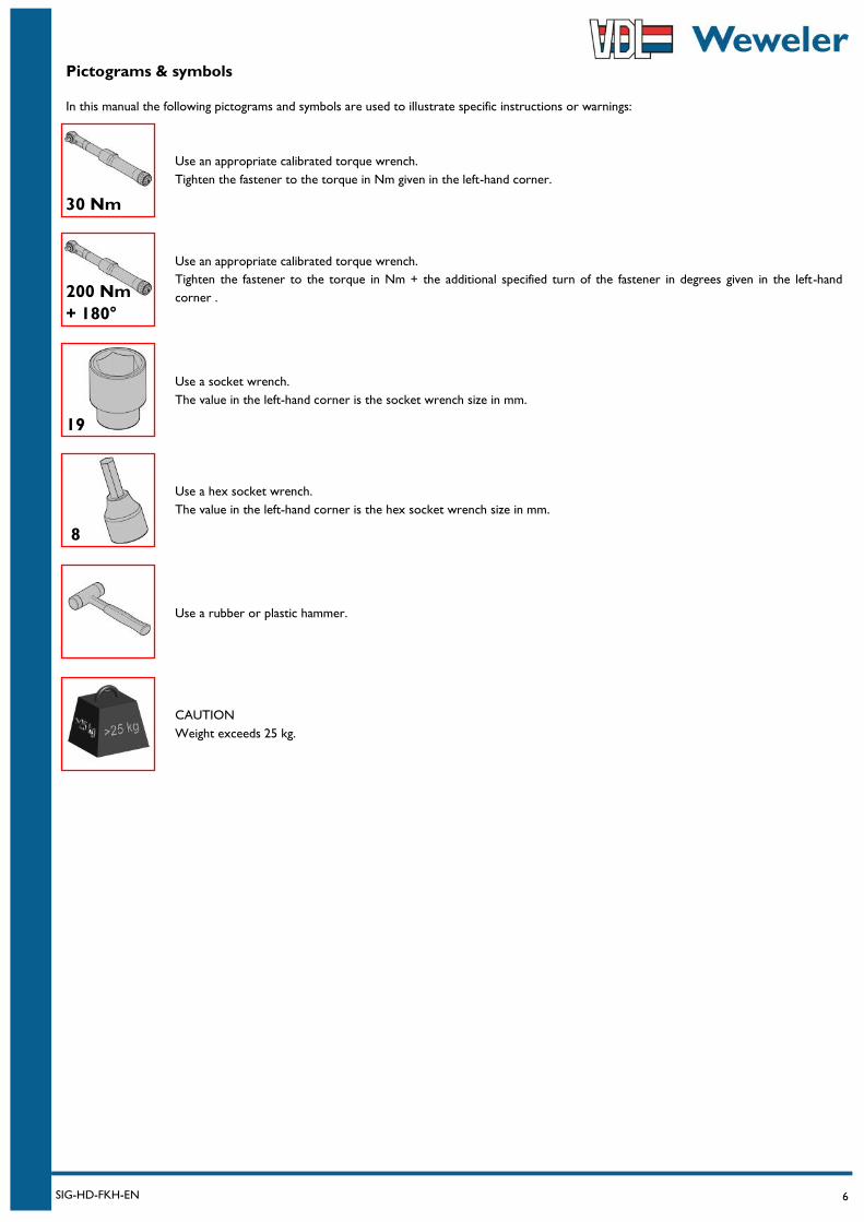
Pictograms & symbols
In this manual the following pictograms and symbols are used to illustrate specific instructions or warnings:
30 Nm
19
8
Use an appropriate calibrated torque wrench.
Tighten the fastener to the torque in Nm given in the left-hand corner.
Use a socket wrench.
The value in the left-hand corner is the socket wrench size in mm.
Use a hex socket wrench.
The value in the left-hand corner is the hex socket wrench size in mm.
CAUTION
Weight exceeds 25 kg.
Use a rubber or plastic hammer.
200 Nm
+ 180°
Use an appropriate calibrated torque wrench.
Tighten the fastener to the torque in Nm + the additional specified turn of the fastener in degrees given in the left-hand
corner .
7 SIG-HD-FKH-EN
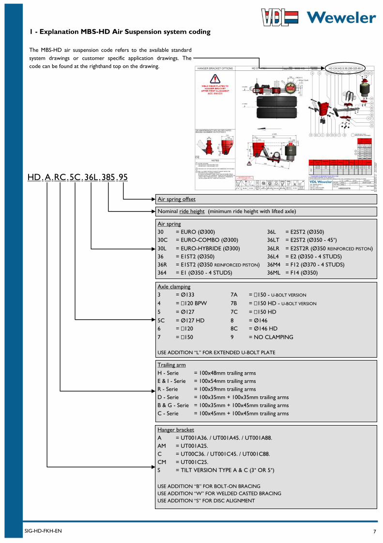
1 - Explanation MBS-HD Air Suspension system coding
HD . A . RC . 5C 36L . 385 . . 95
Hanger bracket
A = UT001A36. / UT001A45. / UT001A88.
AM = UT001A25.
C = UT00C36. / UT001C45. / UT001C88.
CM = UT001C25.
S = TILT VERSION TYPE A & C (3° OR 5°)
USE ADDITION “B” FOR BOLT-ON BRACING
USE ADDITION “W” FOR WELDED CASTED BRACING
USE ADDITION “S” FOR DISC ALIGNMENT
Nominal ride height (minimum ride height with lifted axle)
Air spring offset
Air spring
30 = EURO (Ø300) 36L = E2ST2 (Ø350)
30C = EURO-COMBO (Ø300) 36LT = E2ST2 (Ø350 - 45°)
30L = EURO-HYBRIDE (Ø300) 36LR = E2ST2R (Ø350 REINFORCED PISTON)
36 = E1ST2 (Ø350) 36L4 = E2 (Ø350 - 4 STUDS)
36R = E1ST2 (Ø350 REINFORCED PISTON) 36M4 = F12 (Ø370 - 4 STUDS)
364 = E1 (Ø350 - 4 STUDS) 36ML = F14 (Ø350)
Trailing arm
H - Serie = 100x48mm trailing arms
E & I - Serie = 100x54mm trailing arms
R - Serie = 100x59mm trailing arms
D - Serie = 100x35mm + 100x35mm trailing arms
B & G - Serie = 100x35mm + 100x45mm trailing arms
C - Serie = 100x45mm + 100x45mm trailing arms
Axle clamping
3 = Ø133 7A = 150 - U-BOLT VERSION
4 = 120 BPW 7B = 150 HD - U-BOLT VERSION
5 = Ø127 7C = 150 HD
5C = Ø127 HD 8 = Ø146
6 = 120 8C = Ø146 HD
7 = 150 9 = NO CLAMPING
USE ADDITION “L” FOR EXTENDED U-BOLT PLATE
The MBS-HD air suspension code refers to the available standard
system drawings or customer specific application drawings. The
code can be found at the righthand top on the drawing.
8 SIG-HD-FKH-EN
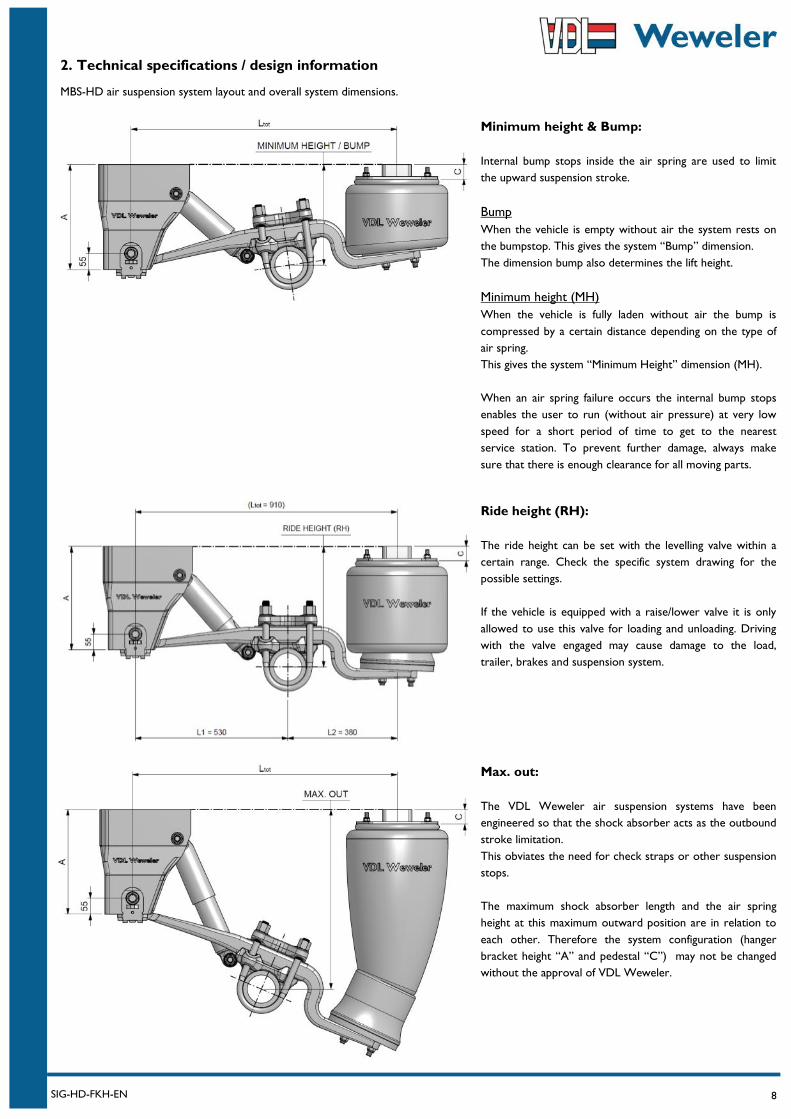
2. Technical specifications / design information
MBS-HD air suspension system layout and overall system dimensions.
Minimum height & Bump:
Internal bump stops inside the air spring are used to limit
the upward suspension stroke.
Bump
When the vehicle is empty without air the system rests on
the bumpstop. This gives the system “Bump” dimension.
The dimension bump also determines the lift height.
Minimum height (MH)
When the vehicle is fully laden without air the bump is
compressed by a certain distance depending on the type of
air spring.
This gives the system “Minimum Height” dimension (MH).
When an air spring failure occurs the internal bump stops
enables the user to run (without air pressure) at very low
speed for a short period of time to get to the nearest
service station. To prevent further damage, always make
sure that there is enough clearance for all moving parts.
Ride height (RH):
The ride height can be set with the levelling valve within a
certain range. Check the specific system drawing for the
possible settings.
If the vehicle is equipped with a raise/lower valve it is only
allowed to use this valve for loading and unloading. Driving
with the valve engaged may cause damage to the load,
trailer, brakes and suspension system.
Max. out:
The VDL Weweler air suspension systems have been
engineered so that the shock absorber acts as the outbound
stroke limitation.
This obviates the need for check straps or other suspension
stops.
The maximum shock absorber length and the air spring
height at this maximum outward position are in relation to
each other. Therefore the system configuration (hanger
bracket height “A” and pedestal “C”) may not be changed
without the approval of VDL Weweler.

9 SIG-HD-FKH-EN
3. Hanger brackets & pedestals
3.1 Dimensions of hanger brackets & pedestal
Hanger bracket (type “C”) with system alignment option.
Standard hanger brackets available in heights (dim. A) from 290mm
up to 560mm.
Separate wear/alignment plates are required.
At FKH used in combination with the welded casted bracing which
creates type “CW”.
Wear plates must be welded after alignment.
Hanger bracket (type “C”) with system alignment option.
This low hanger bracket is only available in a height (dim. A) of
260mm. and only suitable for chassis beams with a maximum width of
150mm.
Separate wear/alignment plates are required.
At FKH used in combination with the welded casted bracing which
creates type “CW”.
Wear plates must be welded after alignment.
3.1a Standard hanger brackets 3.1b Special low hanger bracket
3.1c Pedestals
Pedestal Ø300 air spring
Standard pedestal for Ø300 air
spring.
Available in heights (dim. C)
from 30mm up to 125mm.
Pedestal Ø350 air spring
Standard pedestal for Ø350 air
spring.
Available in heights (dim. C)
from 30mm up to 225mm.
3.2 Alignment of hanger bracket
10 SIG-HD-FKH-EN
3. Hanger brackets & pedestals
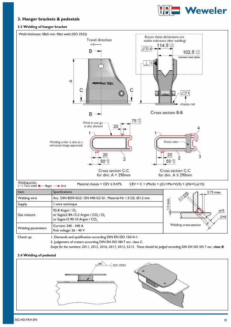
3.3 Welding of hanger bracket
Item Specifications
Welding wire Acc. DIN 8559-SG2 / EN 440-G3 Si1. Material-Nr 1.5125, Ø1.2 mm
Supply 1-wire technique
Gas mixture
92-8 Argon / O2
or Sagox2 84-13-3 Argon / CO2 / O2
or Sagox10 90-10 Argon / CO2
Welding parameters Current: 240 - 340 A
Puls voltage: 26 - 40 V
Weld thickness: S8a5 min. fillet weld (ISO 2553)
Material chassis = CEV 0.47% CEV = C + (Mn/6) + ((Cr+Mo+V)/5) + ((Ni+Cu)/15)
Check up: 1. Demands and qualification according DIN EN ISO 15614-1.
2. Judgement of craters according DIN EN ISO 5817 acc. class C.
Exept for the numbers: 2011, 2012, 2016, 2017, 5012, 5213. Those should be judged according DIN EN ISO 5817 acc. class B.
3.4 Welding of pedestal
11 SIG-HD-FKH-EN
3. Hanger brackets & pedestals
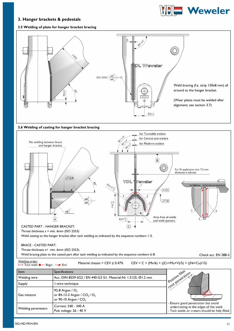
3.5 Welding of plate for hanger bracket bracing
Item Specifications
Welding wire Acc. DIN 8559-SG2 / EN 440-G3 Si1. Material-Nr 1.5125, Ø1.2 mm
Supply 1-wire technique
Gas mixture
92-8 Argon / O2
or 84-13-3 Argon / CO2 / O2
or 90-10 Argon / CO2
Welding parameters Current: 240 - 340 A
Puls voltage: 26 - 40 V
Material chassis = CEV 0.47% CEV = C + (Mn/6) + ((Cr+Mo+V)/5) + ((Ni+Cu)/15)
CASTED PART - HANGER BRACKET:
Throat thickness s = min. 6mm (ISO 2553)
Weld casting to the hanger bracket after tack welding as indicated by the sequence numbers 1-5.
BRACE - CASTED PART:
Throat thickness s= min. 6mm (ISO 2553)
Weld bracing plate to the casted part after tack welding as indicated by the sequence numbers 6-8.
Weld bracing (f.e. strip 150x8 mm) all
around to the hanger bracket.
(Wear plates must be welded after
alignment, see section 3.7)
3.6 Welding of casting for hanger bracket bracing
Check acc. EN 288-3
12 SIG-HD-FKH-EN
3. Hanger brackets & pedestals
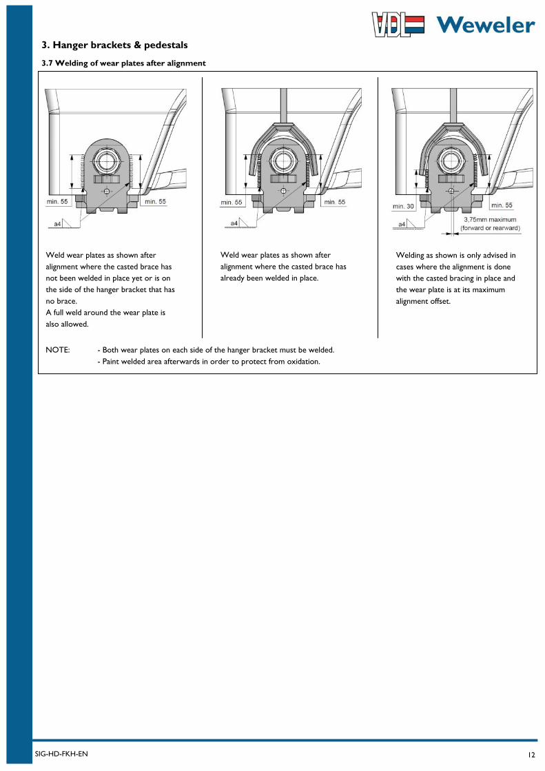
3.7 Welding of wear plates after alignment
Weld wear plates as shown after
alignment where the casted brace has
not been welded in place yet or is on
the side of the hanger bracket that has
no brace.
A full weld around the wear plate is
also allowed.
Weld wear plates as shown after
alignment where the casted brace has
already been welded in place.
Welding as shown is only advised in
cases where the alignment is done
with the casted bracing in place and
the wear plate is at its maximum
alignment offset.
NOTE: - Both wear plates on each side of the hanger bracket must be welded.
- Paint welded area afterwards in order to protect from oxidation.
13 SIG-HD-FKH-EN
4. Axle seat welding
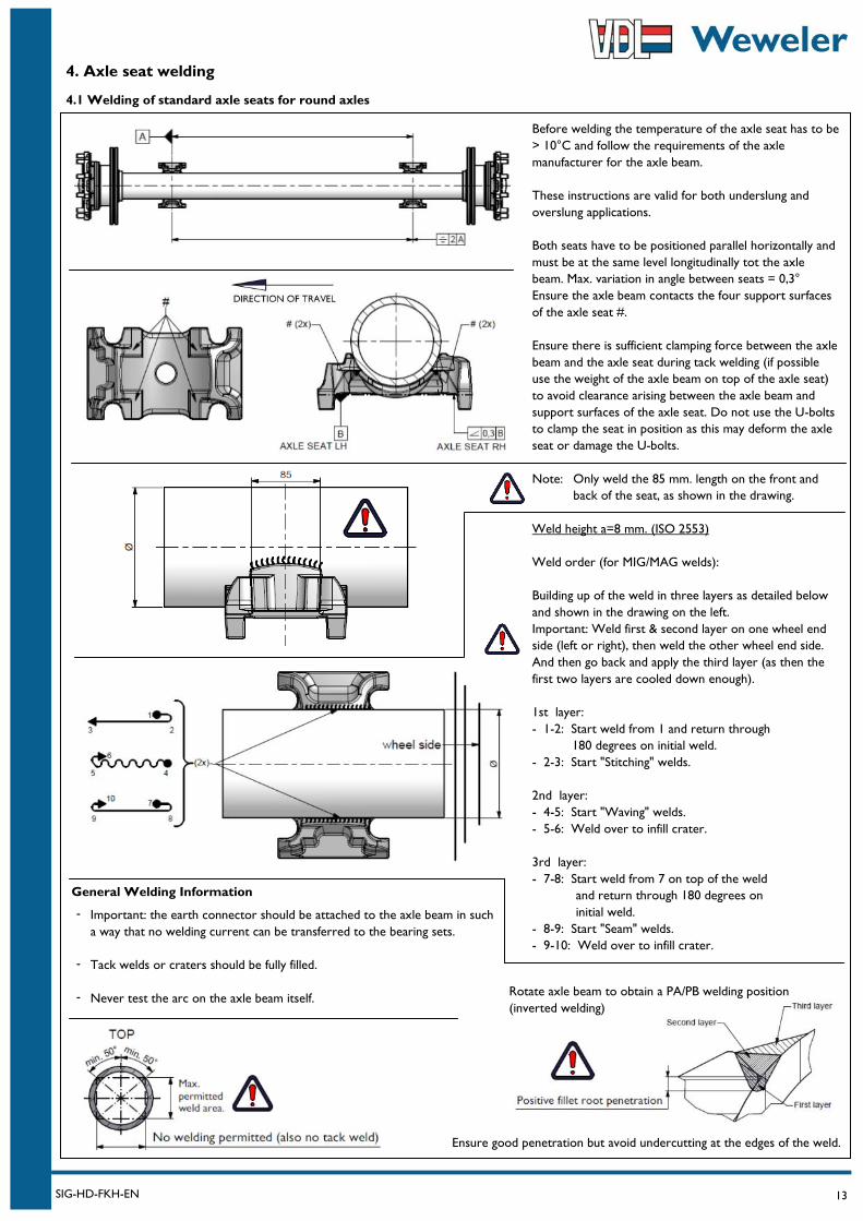
4.1 Welding of standard axle seats for round axles
Before welding the temperature of the axle seat has to be
> 10°C and follow the requirements of the axle
manufacturer for the axle beam.
These instructions are valid for both underslung and
overslung applications.
Both seats have to be positioned parallel horizontally and
must be at the same level longitudinally tot the axle
beam. Max. variation in angle between seats = 0,3°
Ensure the axle beam contacts the four support surfaces
of the axle seat #.
Ensure there is sufficient clamping force between the axle
beam and the axle seat during tack welding (if possible
use the weight of the axle beam on top of the axle seat)
to avoid clearance arising between the axle beam and
support surfaces of the axle seat. Do not use the U-bolts
to clamp the seat in position as this may deform the axle
seat or damage the U-bolts.
Note: Only weld the 85 mm. length on the front and
back of the seat, as shown in the drawing.
Weld height a=8 mm. (ISO 2553)
Weld order (for MIG/MAG welds):
Building up of the weld in three layers as detailed below
and shown in the drawing on the left.
Important: Weld first & second layer on one wheel end
side (left or right), then weld the other wheel end side.
And then go back and apply the third layer (as then the
first two layers are cooled down enough).
1st layer:
- 1-2: Start weld from 1 and return through
180 degrees on initial weld.
- 2-3: Start "Stitching" welds.
2nd layer:
- 4-5: Start "Waving" welds.
- 5-6: Weld over to infill crater.
3rd layer:
- 7-8: Start weld from 7 on top of the weld
and return through 180 degrees on
initial weld.
- 8-9: Start "Seam" welds.
- 9-10: Weld over to infill crater.
Important: the earth connector should be attached to the axle beam in such
a way that no welding current can be transferred to the bearing sets.
Tack welds or craters should be fully filled.
Never test the arc on the axle beam itself.
General Welding Information
Rotate axle beam to obtain a PA/PB welding position
(inverted welding)
-
-
-
Ensure good penetration but avoid undercutting at the edges of the weld.
14 SIG-HD-FKH-EN
4. Axle seat welding
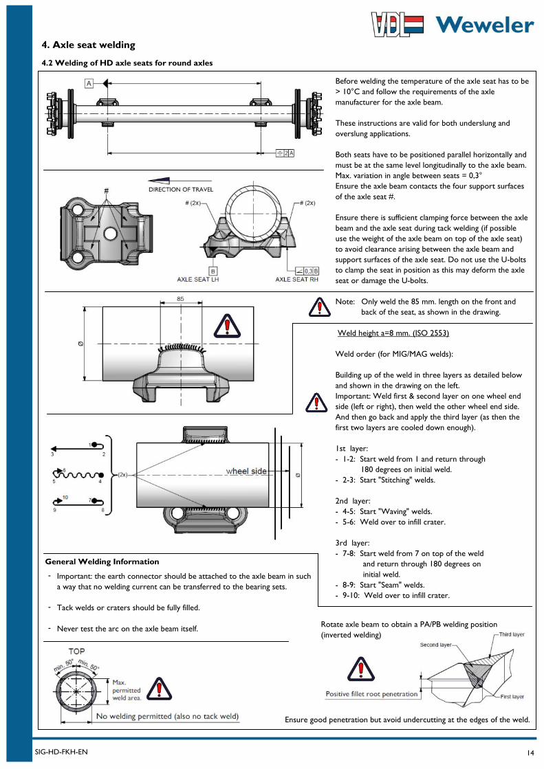
4.2 Welding of HD axle seats for round axles
Before welding the temperature of the axle seat has to be
> 10°C and follow the requirements of the axle
manufacturer for the axle beam.
These instructions are valid for both underslung and
overslung applications.
Both seats have to be positioned parallel horizontally and
must be at the same level longitudinally to the axle beam.
Max. variation in angle between seats = 0,3°
Ensure the axle beam contacts the four support surfaces
of the axle seat #.
Ensure there is sufficient clamping force between the axle
beam and the axle seat during tack welding (if possible
use the weight of the axle beam on top of the axle seat)
to avoid clearance arising between the axle beam and
support surfaces of the axle seat. Do not use the U-bolts
to clamp the seat in position as this may deform the axle
seat or damage the U-bolts.
Note: Only weld the 85 mm. length on the front and
back of the seat, as shown in the drawing.
Weld height a=8 mm. (ISO 2553)
Weld order (for MIG/MAG welds):
Building up of the weld in three layers as detailed below
and shown in the drawing on the left.
Important: Weld first & second layer on one wheel end
side (left or right), then weld the other wheel end side.
And then go back and apply the third layer (as then the
first two layers are cooled down enough).
1st layer:
- 1-2: Start weld from 1 and return through
180 degrees on initial weld.
- 2-3: Start "Stitching" welds.
2nd layer:
- 4-5: Start "Waving" welds.
- 5-6: Weld over to infill crater.
3rd layer:
- 7-8: Start weld from 7 on top of the weld
and return through 180 degrees on
initial weld.
- 8-9: Start "Seam" welds.
- 9-10: Weld over to infill crater.
Important: the earth connector should be attached to the axle beam in such
a way that no welding current can be transferred to the bearing sets.
Tack welds or craters should be fully filled.
Never test the arc on the axle beam itself.
General Welding Information
Rotate axle beam to obtain a PA/PB welding position
(inverted welding)
-
-
-
Ensure good penetration but avoid undercutting at the edges of the weld.

15 SIG-HD-FKH-EN
4. Axle seat welding
4.3 Welding of HD axle seats for square 150mm axles
Before welding the temperature of the axle seat has to be
> 10°C and follow the requirements of the axle
manufacturer for the axle beam.
These instructions are valid for both underslung and
overslung applications with front and rear mounted shock
absorbers.
Bottom and top axle seats have to be positioned parallel
horizontally and must be at the same level longitudinally
to the axle beam. Max. variation in angle between seats =
0,3°
The axle beam must contact the base of the bottom and
top axle seat (X) OR on two points in the radius of the
axle seat on all 4 corners (Y).
Ensure there is sufficient clamping force between the axle
beam and the axle seat during tack welding (if possible
use the weight of the axle beam on top of the axle seat)
to avoid clearance arising between the axle beam and
support surfaces of the axle seat. Do not use the
clamping (U-)bolts to clamp the seat in position as this
may deform the axle seat or damage the (U-)bolts.
Weld height a=8 mm. (ISO 2553)
Weld order (for MIG/MAG welds):
Building up of the weld * in three layers as detailed below
and shown in the drawing on the left.
Important: Weld first & second layer on one wheel end
side (left or right), then weld the other wheel end side.
And then go back and apply the third layer (as then the
first two layers are cooled down enough).
1st layer:
- 1-2: Start weld from 1 and return through
180 degrees on initial weld.
- 2-3: Start "Stitching" welds.
2nd layer:
- 4-5: Start "Waving" welds.
- 5-6: Weld over to infill crater.
3rd layer:
- 7-8: Start weld from 7 on top of the weld
and return through 180 degrees on
initial weld.
- 8-9: Start "Seam" welds.
- 9-10: Weld over to infill crater.
General Welding Information
Important: the earth connector should be attached to the axle beam in such
a way that no welding current can be transferred to the bearing sets.
Tack welds or craters should be fully filled.
Never test the arc on the axle beam itself.
-
-
- Rotate axle beam to obtain a PA/PB welding position.
(inverted welding)
Ensure good penetration but avoid undercutting at the edges of the weld.
16 SIG-HD-FKH-EN
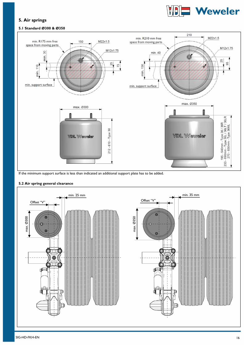
5. Air springs
5.1 Standard Ø300 & Ø350
If the minimum support surface is less than indicated an additional support plate has to be added.
5.2 Air spring general clearance
min. 25 mm
max
. Ø
300
max
. Ø
350
min. 35 mm
Offset “V” Offset “V”
17 SIG-HD-FKH-EN
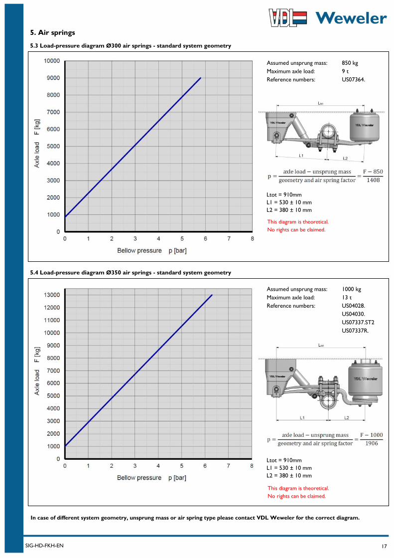
5. Air springs
5.3 Load-pressure diagram Ø300 air springs - standard system geometry
This diagram is theoretical.
No rights can be claimed.
5.4 Load-pressure diagram Ø350 air springs - standard system geometry
Ltot = 910mm
L1 = 530 ± 10 mm
L2 = 380 ± 10 mm
Ltot = 910mm
L1 = 530 ± 10 mm
L2 = 380 ± 10 mm
This diagram is theoretical.
No rights can be claimed.
Assumed unsprung mass: 1000 kg
Maximum axle load: 13 t
Reference numbers: US04028.
US04030.
US07337.ST2
US07337R.
Assumed unsprung mass: 850 kg
Maximum axle load: 9 t
Reference numbers: US07364.
In case of different system geometry, unsprung mass or air spring type please contact VDL Weweler for the correct diagram.
18 SIG-HD-FKH-EN
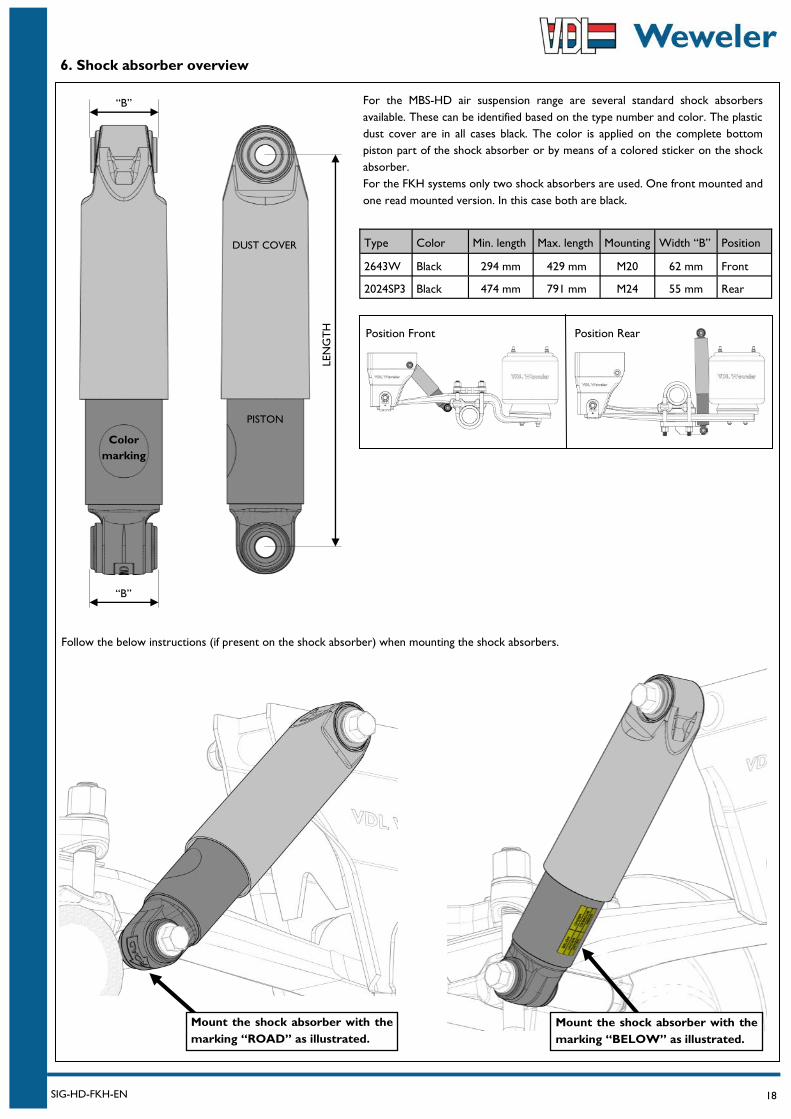
6. Shock absorber overview
Type Color Min. length Max. length Mounting Width “B” Position
2643W Black 294 mm 429 mm M20 62 mm Front
2024SP3 Black 474 mm 791 mm M24 55 mm Rear
Color
marking
“B”
“B”
LEN
GT
H
For the MBS-HD air suspension range are several standard shock absorbers
available. These can be identified based on the type number and color. The plastic
dust cover are in all cases black. The color is applied on the complete bottom
piston part of the shock absorber or by means of a colored sticker on the shock
absorber.
For the FKH systems only two shock absorbers are used. One front mounted and
one read mounted version. In this case both are black.
DUST COVER
PISTON
Mount the shock absorber with the
marking “ROAD” as illustrated.
Mount the shock absorber with the
marking “BELOW” as illustrated.
Follow the below instructions (if present on the shock absorber) when mounting the shock absorbers.
Position Front Position Rear
19 SIG-HD-FKH-EN
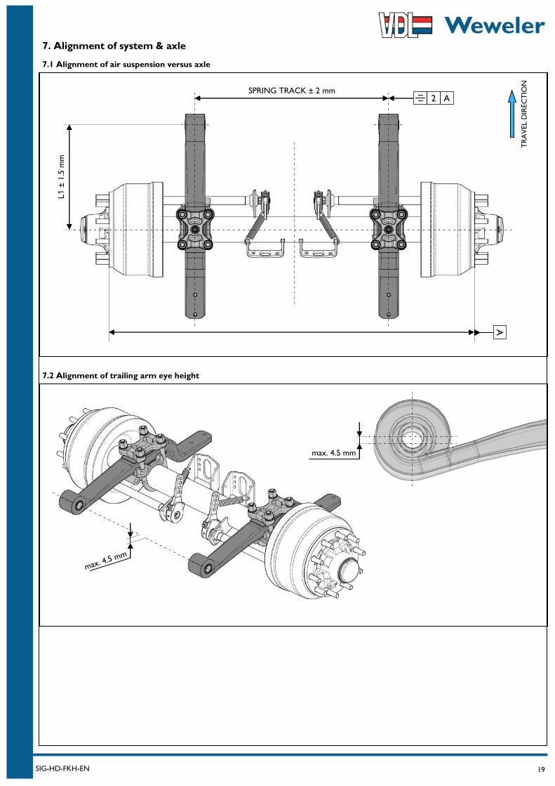
7.2 Alignment of trailing arm eye height
7. Alignment of system & axle
7.1 Alignment of air suspension versus axle
TR
AV
EL D
IREC
TIO
N
SPRING TRACK ± 2 mm
A
2 A
L1 ±
1.5
mm
max. 4.5 mm
max. 4.5 mm
20 SIG-HD-FKH-EN
7. System & axle alignment
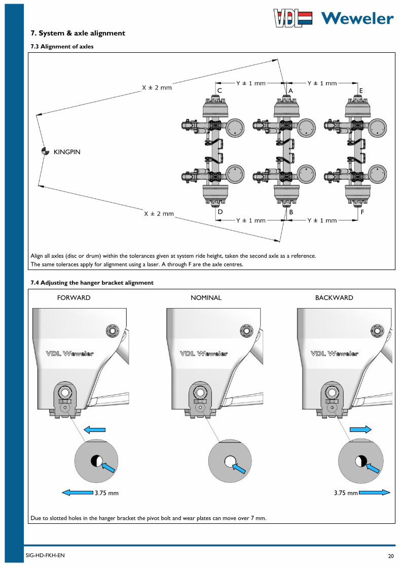
7.3 Alignment of axles
Align all axles (disc or drum) within the tolerances given at system ride height, taken the second axle as a reference.
The same toleraces apply for alignment using a laser. A through F are the axle centres.
7.4 Adjusting the hanger bracket alignment
A
B
C
D
E
F
FORWARD NOMINAL BACKWARD
3.75 mm 3.75 mm
Due to slotted holes in the hanger bracket the pivot bolt and wear plates can move over 7 mm.
KINGPIN
21 SIG-HD-FKH-EN
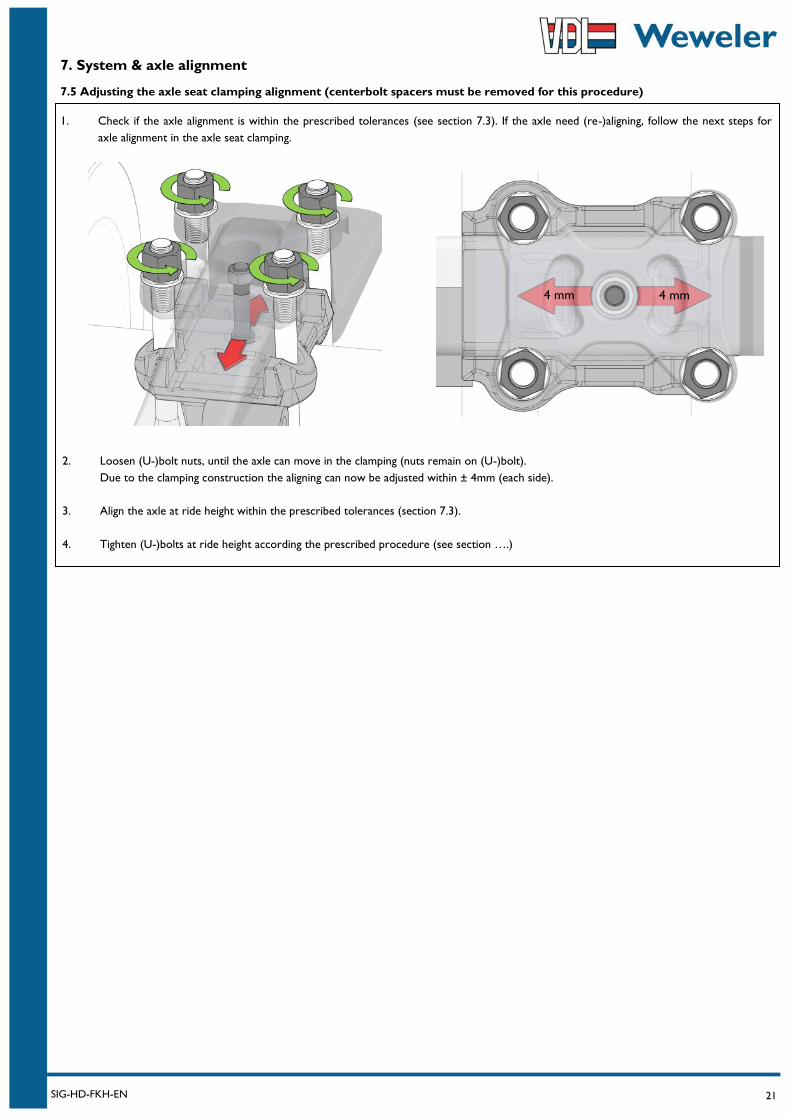
7. System & axle alignment
7.5 Adjusting the axle seat clamping alignment (centerbolt spacers must be removed for this procedure)
1. Check if the axle alignment is within the prescribed tolerances (see section 7.3). If the axle need (re-)aligning, follow the next steps for
axle alignment in the axle seat clamping.
2. Loosen (U-)bolt nuts, until the axle can move in the clamping (nuts remain on (U-)bolt).
Due to the clamping construction the aligning can now be adjusted within ± 4mm (each side).
3. Align the axle at ride height within the prescribed tolerances (section 7.3).
4. Tighten (U-)bolts at ride height according the prescribed procedure (see section ….)
4 mm 4 mm
22 SIG-HD-FKH-EN
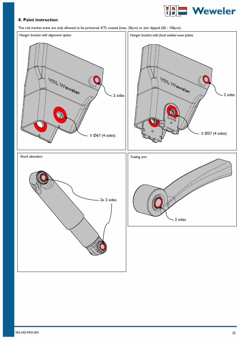
8. Paint instruction
The red market areas are only allowed to be primered, KTL coated (max. 30m) or zinc dipped (50 - 100m).
Hanger bracket with alignment option
≥ Ø67 (4 sides)
2 sides
Trailing arm
2 sides
2x 2 sides
Shock absorbers
Hanger bracket with fixed welded wear plates
≥ Ø57 (4 sides)
2 sides
23 SIG-HD-FKH-EN
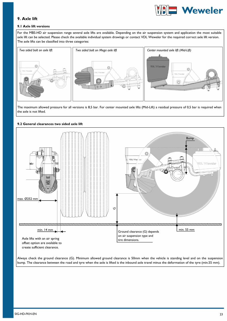
9. Axle lift
For the MBS-HD air suspension range several axle lifts are available. Depending on the air suspension system and application the most suitable
axle lift can be selected. Please check the available individual system drawings or contact VDL Weweler for the required correct axle lift version.
The axle lifts can be classified into three categories:
The maximum allowed pressure for all versions is 8,5 bar. For center mounted axle lifts (Mid-Lift) a residual pressure of 0,5 bar is required when
the axle is not lifted.
9.1 Axle lift versions
9.2 General clearances two sided axle lift
max. Ø252 mm
Always check the ground clearance (G). Minimum allowed ground clearance is 50mm when the vehicle is standing level and on the suspension
bump. The clearance between the road and tyre when the axle is lifted is the inbound axle travel minus the deformation of the tyre (min.55 mm).
min. 14 mm min. 55 mm Ground clearance (G) depends
on air suspension type and
tire dimensions.
Bump
G
Two sided bolt on axle lift Two sided bolt on Mega axle lift Center mounted axle lift (Mid-Lift)
Axle lifts with an air spring
offset option are available to
create sufficient clearance.
24 SIG-HD-FKH-EN
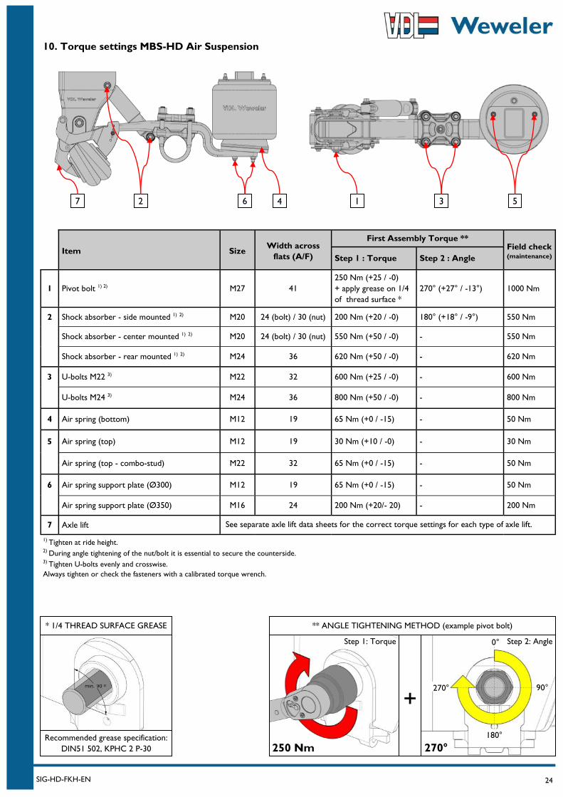
Item Size Width across
flats (A/F)
First Assembly Torque ** Field check (maintenance)
Step 1 : Torque Step 2 : Angle
1 Pivot bolt 1) 2) M27 41
250 Nm (+25 / -0)
+ apply grease on 1/4
of thread surface *
270° (+27° / -13°) 1000 Nm
2 Shock absorber - side mounted 1) 2) M20 24 (bolt) / 30 (nut) 200 Nm (+20 / -0) 180° (+18° / -9°) 550 Nm
Shock absorber - center mounted 1) 2) M20 24 (bolt) / 30 (nut) 550 Nm (+50 / -0) - 550 Nm
Shock absorber - rear mounted 1) 2) M24 36 620 Nm (+50 / -0) - 620 Nm
3 U-bolts M22 3) M22 32 600 Nm (+25 / -0) - 600 Nm
U-bolts M24 3) M24 36 800 Nm (+50 / -0) - 800 Nm
4 Air spring (bottom) M12 19 65 Nm (+0 / -15) - 50 Nm
5 Air spring (top) M12 19 30 Nm (+10 / -0) - 30 Nm
Air spring (top - combo-stud) M22 32 65 Nm (+0 / -15) - 50 Nm
6 Air spring support plate (Ø300) M12 19 65 Nm (+0 / -15) - 50 Nm
Air spring support plate (Ø350) M16 24 200 Nm (+20/- 20) - 200 Nm
7 Axle lift
10. Torque settings MBS-HD Air Suspension
7 3 1 5 6
** ANGLE TIGHTENING METHOD (example pivot bolt)
+
* 1/4 THREAD SURFACE GREASE
250 Nm 270°
Step 1: Torque
Recommended grease specification:
DIN51 502, KPHC 2 P-30
1) Tighten at ride height. 2) During angle tightening of the nut/bolt it is essential to secure the counterside. 3) Tighten U-bolts evenly and crosswise.
Always tighten or check the fasteners with a calibrated torque wrench.
0°
90°
180°
270°
Step 2: Angle
See separate axle lift data sheets for the correct torque settings for each type of axle lift.
2 4
25 SIG-HD-FKH-EN
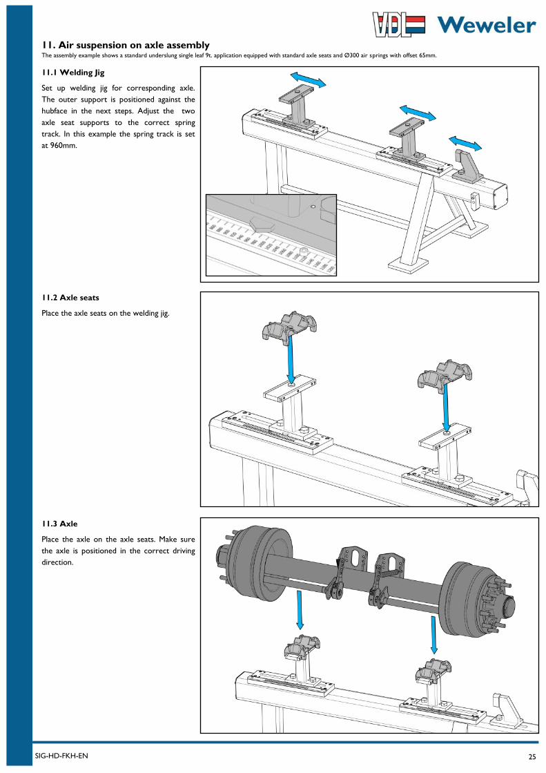
11. Air suspension on axle assembly The assembly example shows a standard underslung single leaf 9t. application equipped with standard axle seats and Ø300 air springs with offset 65mm.
11.1 Welding Jig
Set up welding jig for corresponding axle.
The outer support is positioned against the
hubface in the next steps. Adjust the two
axle seat supports to the correct spring
track. In this example the spring track is set
at 960mm.
11.3 Axle
Place the axle on the axle seats. Make sure
the axle is positioned in the correct driving
direction.
11.2 Axle seats
Place the axle seats on the welding jig.
26 SIG-HD-FKH-EN
11. Air suspension on axle assembly
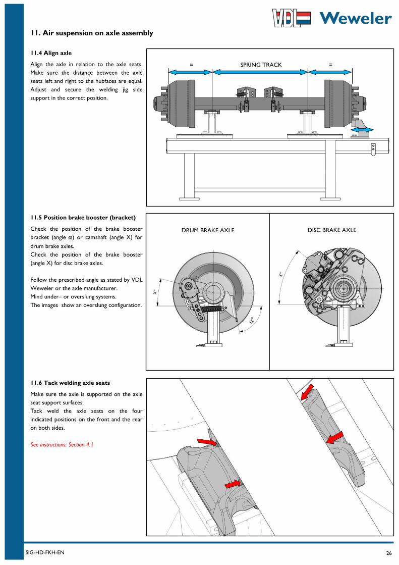
11.4 Align axle
Align the axle in relation to the axle seats.
Make sure the distance between the axle
seats left and right to the hubfaces are equal.
Adjust and secure the welding jig side
support in the correct position.
11.6 Tack welding axle seats
Make sure the axle is supported on the axle
seat support surfaces.
Tack weld the axle seats on the four
indicated positions on the front and the rear
on both sides.
See instructions: Section 4.1
11.5 Position brake booster (bracket)
Check the position of the brake booster
bracket (angle ) or camshaft (angle X) for
drum brake axles.
Check the position of the brake booster
(angle X) for disc brake axles.
Follow the prescribed angle as stated by VDL
Weweler or the axle manufacturer.
Mind under– or overslung systems.
The images show an overslung configuration.
SPRING TRACK = =
DRUM BRAKE AXLE DISC BRAKE AXLE
27 SIG-HD-FKH-EN
11. Air suspension on axle assembly
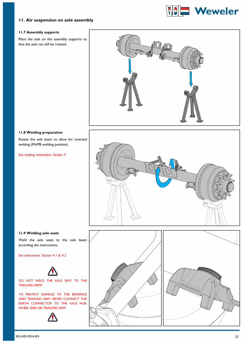
11.7 Assembly supports
Place the axle on the assembly supports so
that the axle can still be rotated.
11.9 Welding axle seats
Weld the axle seats to the axle beam
according the instructions.
See instructions: Section 4.1 & 4.2
DO NOT WELD THE AXLE SEAT TO THE
TRAILING ARM!!
TO PREVENT DAMAGE TO THE BEARINGS
AND TRAILING ARM, NEVER CONNECT THE
EARTH CONNECTOR TO THE AXLE HUB,
WHEEL END OR TRAILING ARM!
11.8 Welding preparation
Rotate the axle beam to allow for inverted
welding (PA/PB welding position).
See welding instructions: Section 4
28 SIG-HD-FKH-EN
11. Air suspension on axle assembly
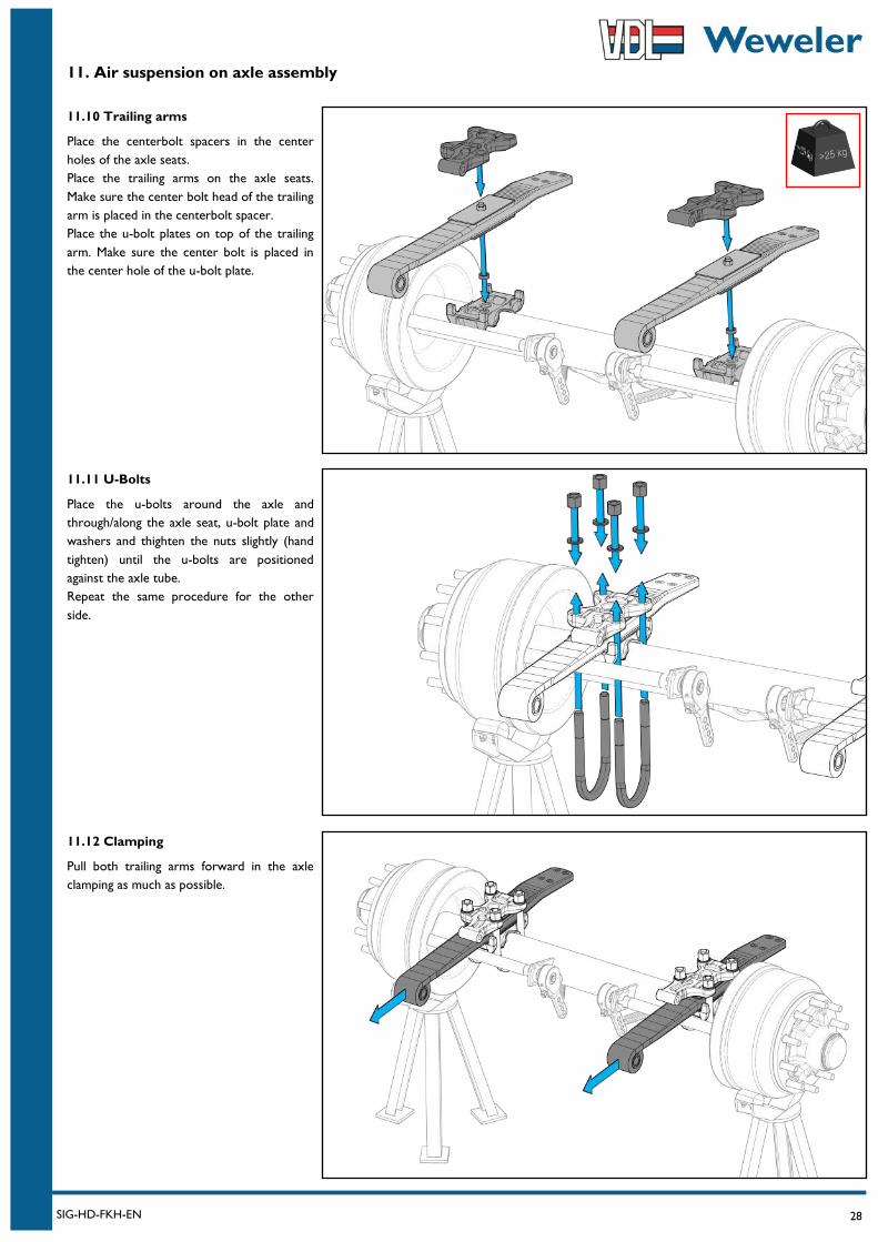
11.10 Trailing arms
Place the centerbolt spacers in the center
holes of the axle seats.
Place the trailing arms on the axle seats.
Make sure the center bolt head of the trailing
arm is placed in the centerbolt spacer.
Place the u-bolt plates on top of the trailing
arm. Make sure the center bolt is placed in
the center hole of the u-bolt plate.
11.12 Clamping
Pull both trailing arms forward in the axle
clamping as much as possible.
11.11 U-Bolts
Place the u-bolts around the axle and
through/along the axle seat, u-bolt plate and
washers and thighten the nuts slightly (hand
tighten) until the u-bolts are positioned
against the axle tube.
Repeat the same procedure for the other
side.
29 SIG-HD-FKH-EN
11. Air suspension on axle assembly
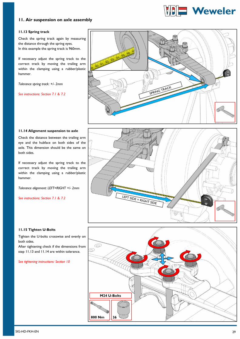
11.13 Spring track
Check the spring track again by measuring
the distance through the spring eyes.
In this example the spring track is 960mm.
If necessary adjust the spring track to the
correct track by moving the trailing arm
within the clamping using a rubber/plastic
hammer.
Tolerance spring track: +/- 2mm
See instructions: Section 7.1 & 7.2
11.15 Tighten U-Bolts
Tighten the U-bolts crosswise and evenly on
both sides.
After tightening check if the dimensions from
step 11.13 and 11.14 are within tolerance.
See tightening instructions: Section 10
11.14 Alignment suspension to axle
Check the distance between the trailing arm
eye and the hubface on both sides of the
axle. This dimension should be the same on
both sides.
If necessary adjust the spring track to the
correct track by moving the trailing arm
within the clamping using a rubber/plastic
hammer.
Tolerance alignment: LEFT=RIGHT +/- 2mm
See instructions: Section 7.1 & 7.2
SPRING TRACK
LEFT SIDE = RIGHT SIDE
800 Nm 36
M24 U-Bolts
30 SIG-HD-FKH-EN
11. Air suspension on axle assembly
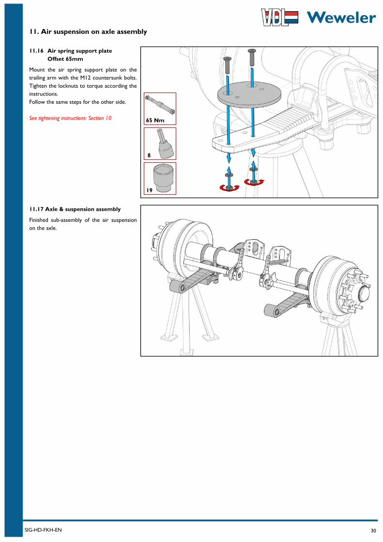
11.16 Air spring support plate
Offset 65mm
Mount the air spring support plate on the
trailing arm with the M12 countersunk bolts.
Tighten the locknuts to torque according the
instructions.
Follow the same steps for the other side.
See tightening instructions: Section 10
11.17 Axle & suspension assembly
Finished sub-assembly of the air suspension
on the axle.
65 Nm
19
8
31 SIG-HD-FKH-EN
12. Final air suspension assembly
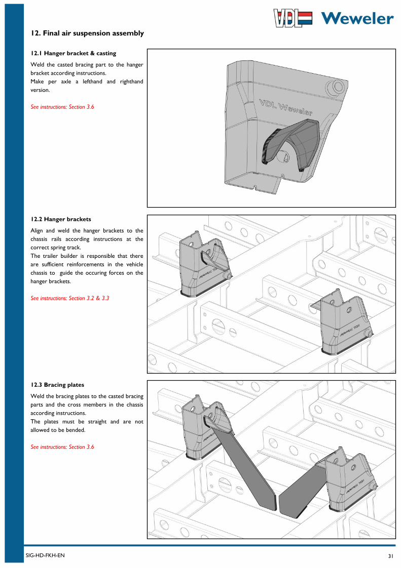
12.3 Bracing plates
Weld the bracing plates to the casted bracing
parts and the cross members in the chassis
according instructions.
The plates must be straight and are not
allowed to be bended.
See instructions: Section 3.6
12.2 Hanger brackets
Align and weld the hanger brackets to the
chassis rails according instructions at the
correct spring track.
The trailer builder is responsible that there
are sufficient reinforcements in the vehicle
chassis to guide the occuring forces on the
hanger brackets.
See instructions: Section 3.2 & 3.3
12.1 Hanger bracket & casting
Weld the casted bracing part to the hanger
bracket according instructions.
Make per axle a lefthand and righthand
version.
See instructions: Section 3.6
32 SIG-HD-FKH-EN
12. Final air suspension assembly
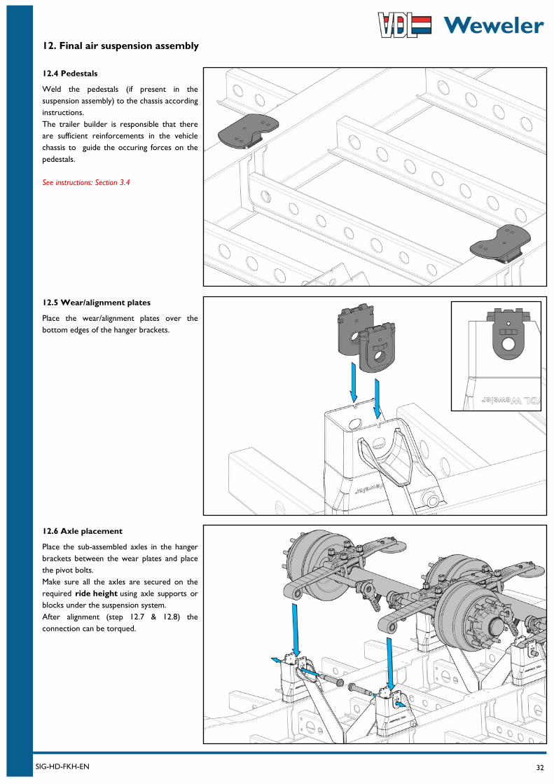
12.6 Axle placement
Place the sub-assembled axles in the hanger
brackets between the wear plates and place
the pivot bolts.
Make sure all the axles are secured on the
required ride height using axle supports or
blocks under the suspension system.
After alignment (step 12.7 & 12.8) the
connection can be torqued.
12.5 Wear/alignment plates
Place the wear/alignment plates over the
bottom edges of the hanger brackets.
12.4 Pedestals
Weld the pedestals (if present in the
suspension assembly) to the chassis according
instructions.
The trailer builder is responsible that there
are sufficient reinforcements in the vehicle
chassis to guide the occuring forces on the
pedestals.
See instructions: Section 3.4
33 SIG-HD-FKH-EN
12. Final air suspension assembly
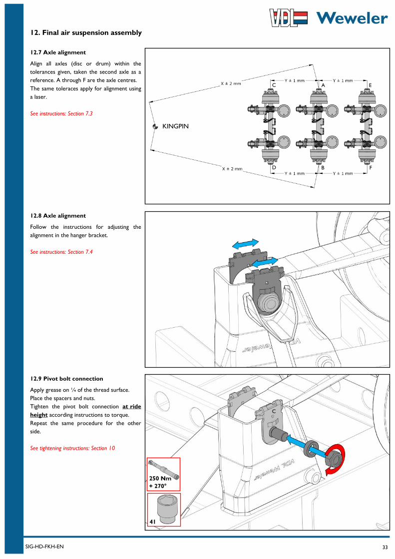
12.9 Pivot bolt connection
Apply grease on ¼ of the thread surface.
Place the spacers and nuts.
Tighten the pivot bolt connection at ride
height according instructions to torque.
Repeat the same procedure for the other
side.
See tightening instructions: Section 10
12.8 Axle alignment
Follow the instructions for adjusting the
alignment in the hanger bracket.
See instructions: Section 7.4
12.7 Axle alignment
Align all axles (disc or drum) within the
tolerances given, taken the second axle as a
reference. A through F are the axle centres.
The same toleraces apply for alignment using
a laser.
See instructions: Section 7.3
C
A
B
C
D
E
F
KINGPIN
250 Nm
+ 270°
41
34 SIG-HD-FKH-EN
12. Final air suspension assembly
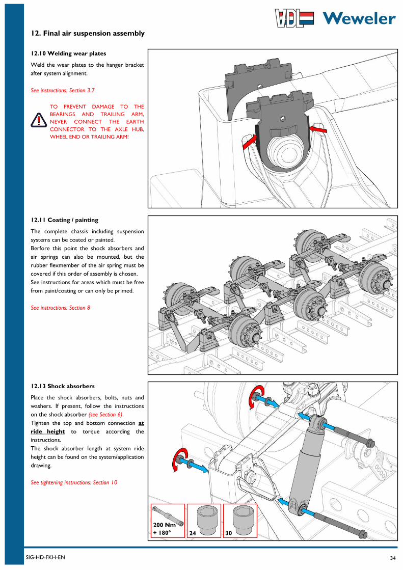
12.13 Shock absorbers
Place the shock absorbers, bolts, nuts and
washers. If present, follow the instructions
on the shock absorber (see Section 6).
Tighten the top and bottom connection at
ride height to torque according the
instructions.
The shock absorber length at system ride
height can be found on the system/application
drawing.
See tightening instructions: Section 10
12.11 Coating / painting
The complete chassis including suspension
systems can be coated or painted.
Berfore this point the shock absorbers and
air springs can also be mounted, but the
rubber flexmember of the air spring must be
covered if this order of assembly is chosen.
See instructions for areas which must be free
from paint/coating or can only be primed.
See instructions: Section 8
12.10 Welding wear plates
Weld the wear plates to the hanger bracket
after system alignment.
See instructions: Section 3.7
TO PREVENT DAMAGE TO THE
BEARINGS AND TRAILING ARM,
NEVER CONNECT THE EARTH
CONNECTOR TO THE AXLE HUB,
WHEEL END OR TRAILING ARM!
200 Nm
+ 180° 24 30
35 SIG-HD-FKH-EN
12. Final air suspension assembly
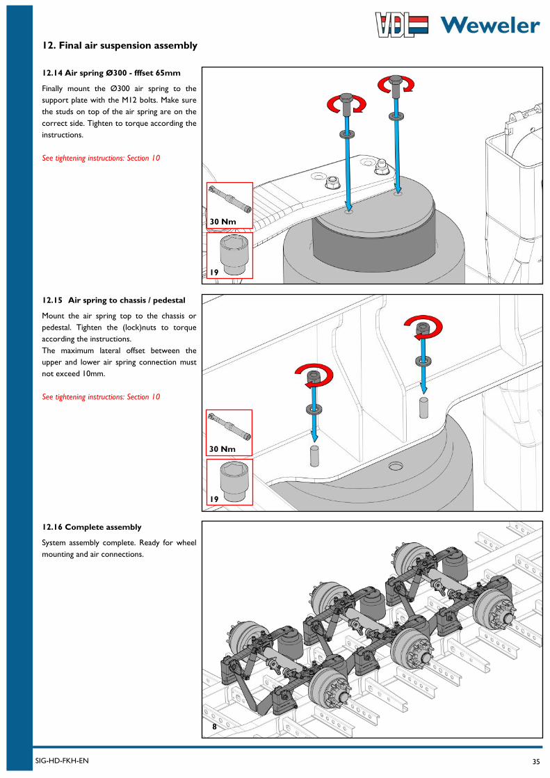
12.16 Complete assembly
System assembly complete. Ready for wheel
mounting and air connections.
12.14 Air spring Ø300 - fffset 65mm
Finally mount the Ø300 air spring to the
support plate with the M12 bolts. Make sure
the studs on top of the air spring are on the
correct side. Tighten to torque according the
instructions.
See tightening instructions: Section 10
12.15 Air spring to chassis / pedestal
Mount the air spring top to the chassis or
pedestal. Tighten the (lock)nuts to torque
according the instructions.
The maximum lateral offset between the
upper and lower air spring connection must
not exceed 10mm.
See tightening instructions: Section 10
19
30 Nm
8
30 Nm
19
36 SIG-HD-FKH-EN
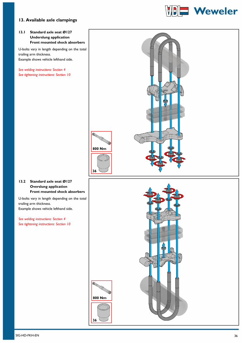
13. Available axle clampings
13.1 Standard axle seat Ø127
Underslung application
Front mounted shock absorbers
U-bolts vary in length depending on the total
trailing arm thickness.
Example shows vehicle lefthand side.
See welding instructions: Section 4
See tightening instructions: Section 10
13.2 Standard axle seat Ø127
Overslung application
Front mounted shock absorbers
U-bolts vary in length depending on the total
trailing arm thickness.
Example shows vehicle lefthand side.
See welding instructions: Section 4
See tightening instructions: Section 10
36
800 Nm
36
800 Nm
37 SIG-HD-FKH-EN
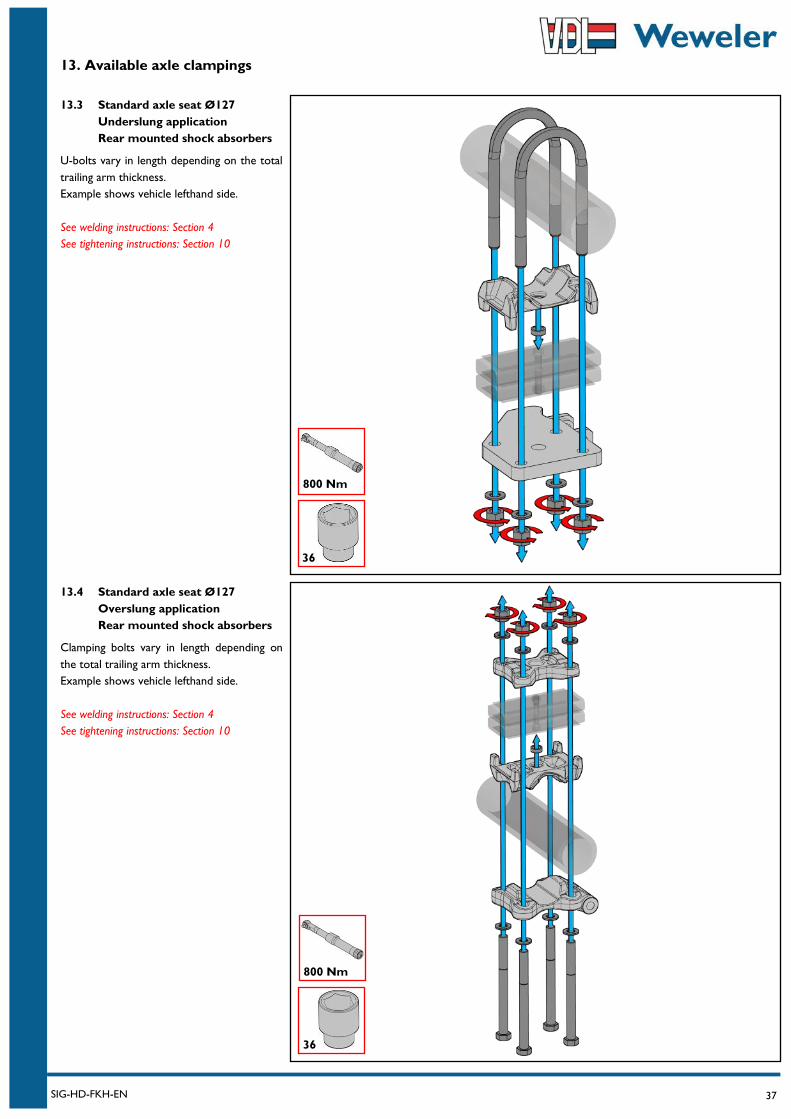
13. Available axle clampings
13.3 Standard axle seat Ø127
Underslung application
Rear mounted shock absorbers
U-bolts vary in length depending on the total
trailing arm thickness.
Example shows vehicle lefthand side.
See welding instructions: Section 4
See tightening instructions: Section 10
13.4 Standard axle seat Ø127
Overslung application
Rear mounted shock absorbers
Clamping bolts vary in length depending on
the total trailing arm thickness.
Example shows vehicle lefthand side.
See welding instructions: Section 4
See tightening instructions: Section 10
36
800 Nm
36
800 Nm

38 SIG-HD-FKH-EN
13. Available axle clampings
13.5 HD axle seat Ø127
Underslung application
Front mounted shock absorbers
U-bolts vary in length depending on the total
trailing arm thickness.
Example shows vehicle lefthand side.
See welding instructions: Section 4
See tightening instructions: Section 10
13.6 HD axle seat Ø127
Overslung application
Front mounted shock absorbers
U-bolts vary in length depending on the total
trailing arm thickness.
Example shows vehicle lefthand side.
See welding instructions: Section 4
See tightening instructions: Section 10
36
800 Nm
36
800 Nm

39 SIG-HD-FKH-EN
13. Available axle clampings
13.7 HD axle seat Ø127
Underslung application
Rear mounted shock absorbers
U-bolts vary in length depending on the total
trailing arm thickness.
Example shows vehicle lefthand side.
See welding instructions: Section 4
See tightening instructions: Section 10
13.8 HD axle seat Ø127
Overslung application
Rear mounted shock absorbers
Clamping bolts vary in length depending on
the total trailing arm thickness.
Example shows vehicle lefthand side.
See welding instructions: Section 4
See tightening instructions: Section 10
36
800 Nm
36
800
40 SIG-HD-FKH-EN
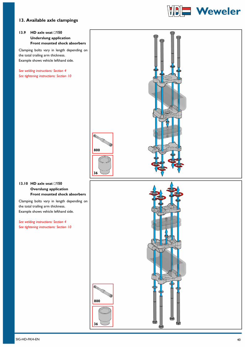
13. Available axle clampings
13.9 HD axle seat 150
Underslung application
Front mounted shock absorbers
Clamping bolts vary in length depending on
the total trailing arm thickness.
Example shows vehicle lefthand side.
See welding instructions: Section 4
See tightening instructions: Section 10
13.10 HD axle seat 150
Overslung application
Front mounted shock absorbers
Clamping bolts vary in length depending on
the total trailing arm thickness.
Example shows vehicle lefthand side.
See welding instructions: Section 4
See tightening instructions: Section 10
36
800
36
800
41 SIG-HD-FKH-EN
13. Available axle clampings
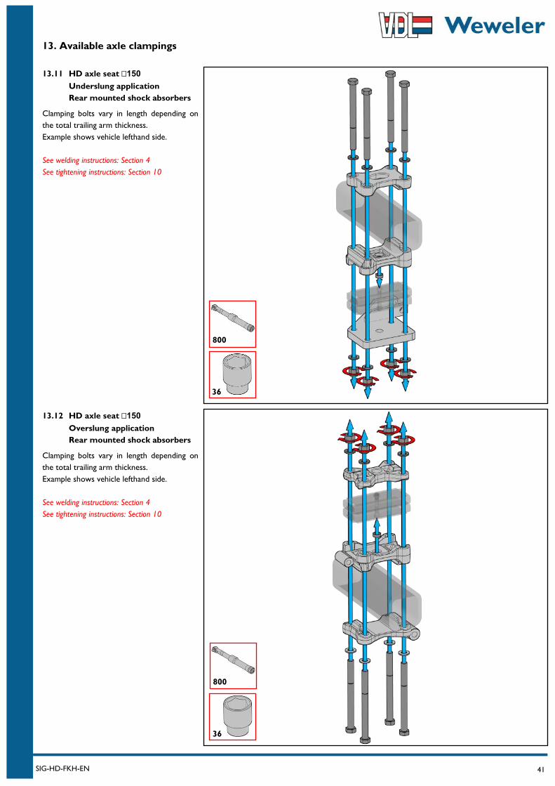
13.11 HD axle seat 150
Underslung application
Rear mounted shock absorbers
Clamping bolts vary in length depending on
the total trailing arm thickness.
Example shows vehicle lefthand side.
See welding instructions: Section 4
See tightening instructions: Section 10
13.12 HD axle seat 150
Overslung application
Rear mounted shock absorbers
Clamping bolts vary in length depending on
the total trailing arm thickness.
Example shows vehicle lefthand side.
See welding instructions: Section 4
See tightening instructions: Section 10
36
800
36
800
42 SIG-HD-FKH-EN
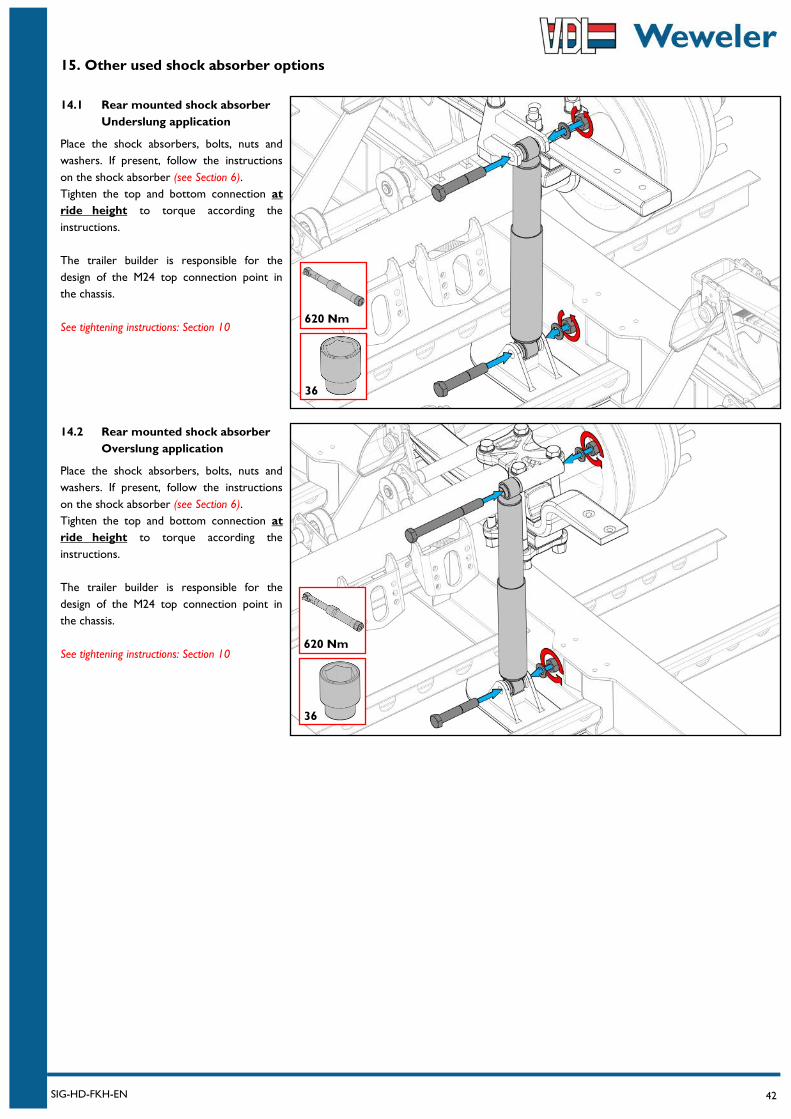
15. Other used shock absorber options
14.2 Rear mounted shock absorber
Overslung application
Place the shock absorbers, bolts, nuts and
washers. If present, follow the instructions
on the shock absorber (see Section 6).
Tighten the top and bottom connection at
ride height to torque according the
instructions.
The trailer builder is responsible for the
design of the M24 top connection point in
the chassis.
See tightening instructions: Section 10
14.1 Rear mounted shock absorber
Underslung application
Place the shock absorbers, bolts, nuts and
washers. If present, follow the instructions
on the shock absorber (see Section 6).
Tighten the top and bottom connection at
ride height to torque according the
instructions.
The trailer builder is responsible for the
design of the M24 top connection point in
the chassis.
See tightening instructions: Section 10
620 Nm
36
620 Nm
36

43 SIG-HD-FKH-EN
15. Other used air spring options
15.1b Air spring Ø300
Offset 30 or 50mm
Finally mount the support plate with the
Ø300 air spring to the trailing arm with the
M12 bolts. Tighten to torque according the
instructions.
The illustration shows an assembly that
creates an air spring offset of 50mm using the
outer most holes of the support plate. The
other holes create an offset of 30mm.
See tightening instructions: Section 10
15.1a Air spring Ø300
Offset 30 or 50mm
First mount the M12 press nut on the
support plate with a rubber/plastic hammer
until the collar is fully pressed into the plate
and the nut lies flush with the plate (see
illustration on the far right).
Next mount the Ø300 air spring to the
support plate with the M12 countersunk
bolts. Make sure the studs on top of the air
spring are on the correct side. Tighten to
torque according the instructions.
See tightening instructions: Section 10
65 Nm
19
30 Nm
8
30
50
44 SIG-HD-FKH-EN
15. Other used air spring options
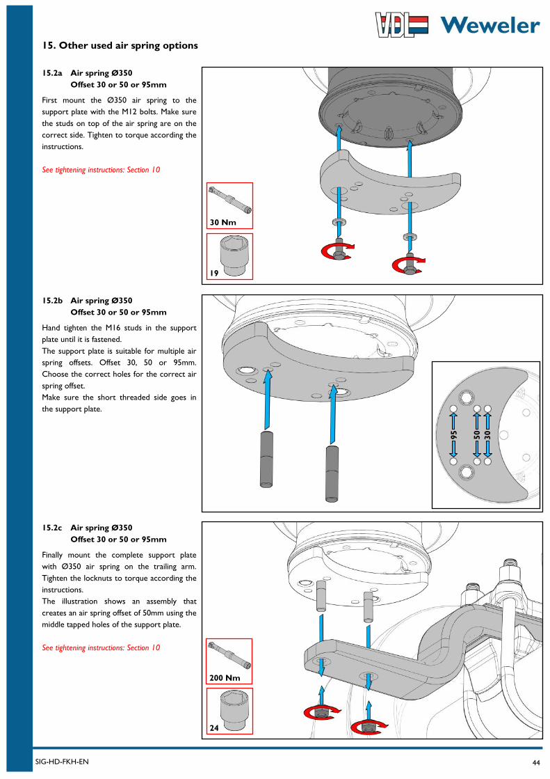
15.2c Air spring Ø350
Offset 30 or 50 or 95mm
Finally mount the complete support plate
with Ø350 air spring on the trailing arm.
Tighten the locknuts to torque according the
instructions.
The illustration shows an assembly that
creates an air spring offset of 50mm using the
middle tapped holes of the support plate.
See tightening instructions: Section 10
15.2b Air spring Ø350
Offset 30 or 50 or 95mm
Hand tighten the M16 studs in the support
plate until it is fastened.
The support plate is suitable for multiple air
spring offsets. Offset 30, 50 or 95mm.
Choose the correct holes for the correct air
spring offset.
Make sure the short threaded side goes in
the support plate.
15.2a Air spring Ø350
Offset 30 or 50 or 95mm
First mount the Ø350 air spring to the
support plate with the M12 bolts. Make sure
the studs on top of the air spring are on the
correct side. Tighten to torque according the
instructions.
See tightening instructions: Section 10
30
50
95
19
30 Nm
200 Nm
24
45 SIG-HD-FKH-EN
15. Other used air spring options
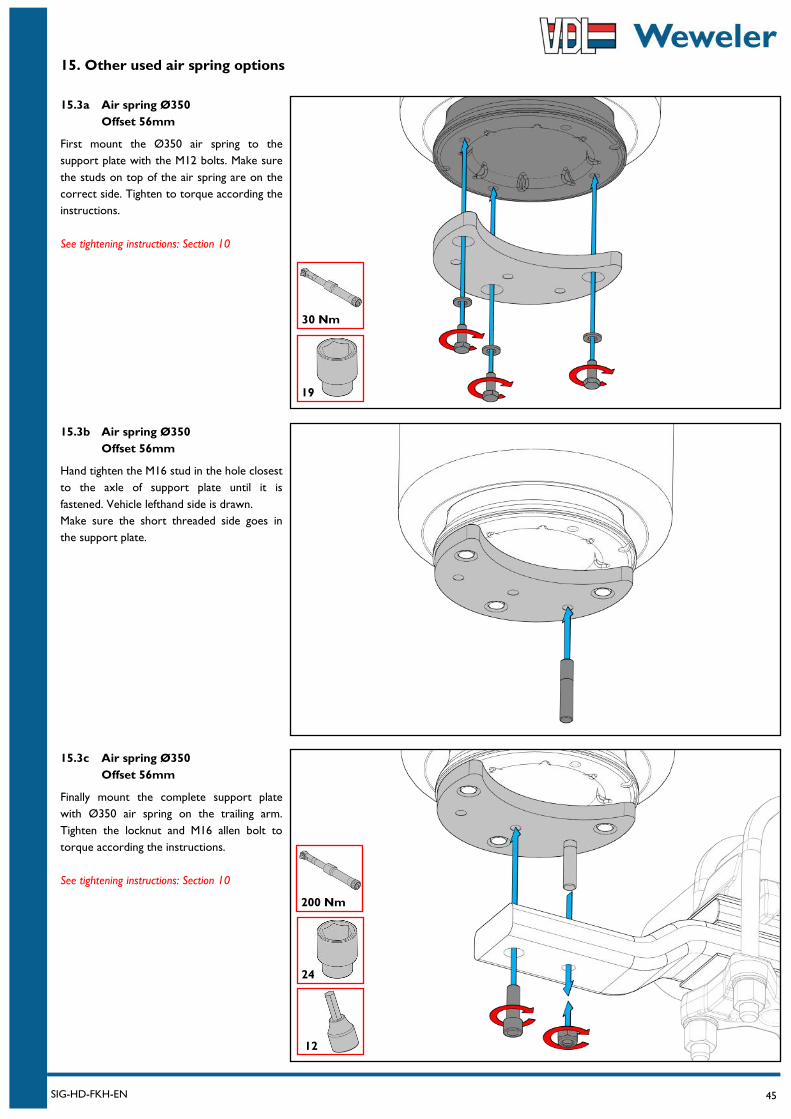
15.3c Air spring Ø350
Offset 56mm
Finally mount the complete support plate
with Ø350 air spring on the trailing arm.
Tighten the locknut and M16 allen bolt to
torque according the instructions.
See tightening instructions: Section 10
15.3b Air spring Ø350
Offset 56mm
Hand tighten the M16 stud in the hole closest
to the axle of support plate until it is
fastened. Vehicle lefthand side is drawn.
Make sure the short threaded side goes in
the support plate.
15.3a Air spring Ø350
Offset 56mm
First mount the Ø350 air spring to the
support plate with the M12 bolts. Make sure
the studs on top of the air spring are on the
correct side. Tighten to torque according the
instructions.
See tightening instructions: Section 10
19
30 Nm
200 Nm
24
12
46 SIG-HD-FKH-EN
15. Other used air spring options
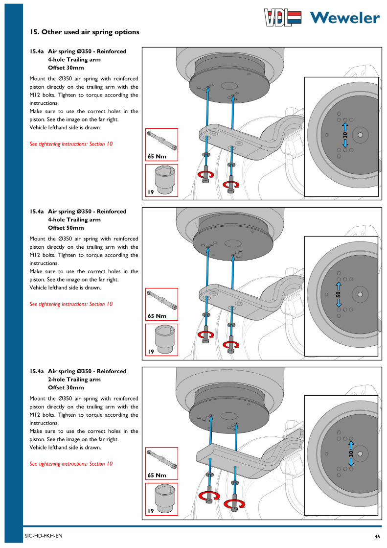
15.4a Air spring Ø350 - Reinforced
2-hole Trailing arm
Offset 30mm
Mount the Ø350 air spring with reinforced
piston directly on the trailing arm with the
M12 bolts. Tighten to torque according the
instructions.
Make sure to use the correct holes in the
piston. See the image on the far right.
Vehicle lefthand side is drawn.
See tightening instructions: Section 10
15.4a Air spring Ø350 - Reinforced
4-hole Trailing arm
Offset 50mm
Mount the Ø350 air spring with reinforced
piston directly on the trailing arm with the
M12 bolts. Tighten to torque according the
instructions.
Make sure to use the correct holes in the
piston. See the image on the far right.
Vehicle lefthand side is drawn.
See tightening instructions: Section 10
15.4a Air spring Ø350 - Reinforced
4-hole Trailing arm
Offset 30mm
Mount the Ø350 air spring with reinforced
piston directly on the trailing arm with the
M12 bolts. Tighten to torque according the
instructions.
Make sure to use the correct holes in the
piston. See the image on the far right.
Vehicle lefthand side is drawn.
See tightening instructions: Section 10
19
65 Nm
30
50
19
65 Nm
19
65 Nm
30
47 SIG-HD-FKH-EN
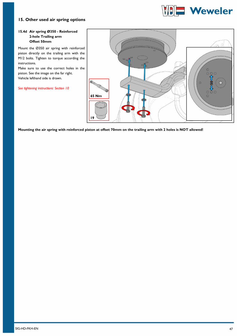
15. Other used air spring options
Mounting the air spring with reinforced piston at offset 70mm on the trailing arm with 2 holes is NOT allowed!
15.4d Air spring Ø350 - Reinforced
2-hole Trailing arm
Offset 50mm
Mount the Ø350 air spring with reinforced
piston directly on the trailing arm with the
M12 bolts. Tighten to torque according the
instructions.
Make sure to use the correct holes in the
piston. See the image on the far right.
Vehicle lefthand side is drawn.
See tightening instructions: Section 10
19
65 Nm
50
48 SIG-HD-FKH-EN
Notes
………………………………………………………………………………………………………………………………………………………
………………………………………………………………………………………………………………………………………………………
………………………………………………………………………………………………………………………………………………………
………………………………………………………………………………………………………………………………………………………
………………………………………………………………………………………………………………………………………………………
………………………………………………………………………………………………………………………………………………………
………………………………………………………………………………………………………………………………………………………
………………………………………………………………………………………………………………………………………………………
………………………………………………………………………………………………………………………………………………………
………………………………………………………………………………………………………………………………………………………
………………………………………………………………………………………………………………………………………………………
………………………………………………………………………………………………………………………………………………………
………………………………………………………………………………………………………………………………………………………
………………………………………………………………………………………………………………………………………………………
………………………………………………………………………………………………………………………………………………………
………………………………………………………………………………………………………………………………………………………
………………………………………………………………………………………………………………………………………………………
………………………………………………………………………………………………………………………………………………………
………………………………………………………………………………………………………………………………………………………
………………………………………………………………………………………………………………………………………………………
………………………………………………………………………………………………………………………………………………………
………………………………………………………………………………………………………………………………………………………
………………………………………………………………………………………………………………………………………………………
………………………………………………………………………………………………………………………………………………………
………………………………………………………………………………………………………………………………………………………
………………………………………………………………………………………………………………………………………………………