mbari-isus v2 operation manual - british … v2 operation manual document number: sat-dn-272...
TRANSCRIPT

MBARI-ISUS V2 Operation Manual
Document Number: SAT-DN-272
Revision G.1, August 2006
For use with MBARI-ISUS V2 and Firmware rev. 2.8

Revision: G.1 Document Number: SAT-DN-272 - Copyright © 2005 by Satlantic - Page: i
Revision: G.1 Document Number: SAT-DN-272 - Copyright © 2005 by Satlantic - Page: ii
Operation Manual for MBARI-ISUS V2
Document Number SAT-DN-272
Prepared by: Satlantic Incorporated Richmond Terminal, Pier 9 3481 North Marginal Road Halifax, Nova Scotia Canada B3K 5X8 Tel (902) 492-4780 Fax (902) 492-4781
Copyright © 2005 by Satlantic This document contains information proprietary to Satlantic or to a third party to which Satlantic may have legal obligation to protect such information from unauthorized disclosure, use or duplication. Any disclosure, use or duplication of this document, in whole or in part, or of any of the information contained herein for any purpose other than the specific purpose for which it was disclosed is expressly prohibited, except as Satlantic may otherwise agree to in writing.
SYSTEM
MBARI-ISUS V2
SECTION
TABLE OF CONTENTS
Revision: G.1 Document Number: SAT-DN-272 - Copyright © 2003 by Satlantic - Page: iii
A. OVERVIEW.....................................................................................................................A-1 PURPOSE ..............................................................................................................................A-1 BACKGROUND .......................................................................................................................A-2 FEATURES.............................................................................................................................A-2 SPECIFICATIONS ....................................................................................................................A-3
Performance.................................................................................................................................A-3 Optics...........................................................................................................................................A-3 Electrical Characteristics.............................................................................................................A-3 Physical Characteristics ..............................................................................................................A-3
PRINCIPLE OF OPERATION ......................................................................................................A-4 CALIBRATION ........................................................................................................................A-5 OPERATIONAL SUMMARY........................................................................................................A-5 MAJOR COMPONENTS ............................................................................................................A-6
Instrument Body...........................................................................................................................A-6 Connector End Cap......................................................................................................................A-8
Connectors...............................................................................................................................A-8 Non-isolated Input Power Port.............................................................................................A-8 Isolated Power and Telemetry Port......................................................................................A-9 Isolated Analog Output........................................................................................................A-9 Auxiliary Non-Isolated Power, USB and Non-Isolated Telemetry.........................................A-10
Sacrificial Anode ....................................................................................................................A-10 Power Supply .............................................................................................................................A-11 Probe End Cap ...........................................................................................................................A-11
Probe ......................................................................................................................................A-12 Standard Probe Guard ...........................................................................................................A-12 Biofouling Guard....................................................................................................................A-13
How the Biofouling Guard Works...........................................................................................A-13 B. SAFETY & HAZARDS.....................................................................................................B-1
PERSONAL SAFETY ................................................................................................................B-1 INSTRUMENTS ........................................................................................................................B-1 CABLE ..................................................................................................................................B-2 CONNECTIONS .......................................................................................................................B-2 TROUBLESHOOTING ...............................................................................................................B-2 RECOVERY ............................................................................................................................B-2
C. START UP ......................................................................................................................C-1 PREPARATION .......................................................................................................................C-1 CONNECT THE CABLES...........................................................................................................C-2 TELEMETRY ACQUISITION USING SATVIEW ...............................................................................C-3 TELEMETRY ACQUISITION WITH A SEABIRD CTD.......................................................................C-4 DEPLOYMENT EXAMPLE..........................................................................................................C-5
D. OPERATION...................................................................................................................D-1 OPERATING MODES ...............................................................................................................D-1
Continuous...................................................................................................................................D-1 Fixed Time....................................................................................................................................D-1 Scheduled ....................................................................................................................................D-1 Benchtop......................................................................................................................................D-3 Triggered......................................................................................................................................D-3
FRAME OUTPUT MODES .........................................................................................................D-4 COMMUNICATING WITH THE ISUS ............................................................................................D-7
How to reach the root menu.........................................................................................................D-7 MENUS .................................................................................................................................D-7
Configuration Menu .....................................................................................................................D-7
SYSTEM
MBARI-ISUS V2
SECTION
TABLE OF CONTENTS
Revision: G.1 Document Number: SAT-DN-272 - Copyright © 2003 by Satlantic - Page: iv
Baudrate ............................................................................................................................D-8 Deployment Counter...........................................................................................................D-8
Setup Menu ..................................................................................................................................D-8 Output Setup Menu ................................................................................................................D-9
Status Messages................................................................................................................D-9 Transfer Frame Mode .........................................................................................................D-9 Logging of Frames to File....................................................................................................D-9 Log File in Scheduled Mode................................................................................................D-9 Nitrate and Auxiliary DAC Range.........................................................................................D-9
Deployment Setup Menu ......................................................................................................D-10 ISUS Deployment Mode....................................................................................................D-10 Initial Delay in CONTINOUS Mode......................................................................................D-10 Fixed Operational Time.....................................................................................................D-10
Spectrometer Setup Menu ....................................................................................................D-10 Integration Period .............................................................................................................D-10 Collection Rate.................................................................................................................D-10 Spectrometer Coefficients.................................................................................................D-10
Lamp Setup Menu ................................................................................................................D-10 Power-On Warm-up Period ...............................................................................................D-11 Reference Diode...............................................................................................................D-11
Fitting Setup Menu ...............................................................................................................D-11 Fitting Range....................................................................................................................D-11 Baseline Order .................................................................................................................D-12 Seawater Dark Samples ...................................................................................................D-12
File Menu....................................................................................................................................D-12 List commands .................................................................................................................D-13 Output commands ............................................................................................................D-13 Upload commands............................................................................................................D-13 Download commands .......................................................................................................D-13 Erase commands..............................................................................................................D-14
Info Menu....................................................................................................................................D-14 Build Info ..........................................................................................................................D-14 Disk Info...........................................................................................................................D-14 Clock Info .........................................................................................................................D-15 Pixel to Wavelength..........................................................................................................D-15 Lamp On Time (Odometer) ...............................................................................................D-15 DAC menu........................................................................................................................D-15
USB / SCI Toggle Menu..............................................................................................................D-15 Reboot command.......................................................................................................................D-15
USING THE MENUS ...............................................................................................................D-15 Checking instrument values ......................................................................................................D-15 Setting up for Scheduled Deployment.......................................................................................D-16 Setting up for Continuous Deployment .....................................................................................D-16
A NOTE ABOUT POWER REMOVAL ........................................................................................D-16 E. RECOVERY ....................................................................................................................E-1
F. MAINTENANCE .............................................................................................................. F-1 PREVENTATIVE MAINTENANCE ................................................................................................ F-1
Cleaning the Probe....................................................................................................................... F-1 Assembling the Biofouling Guard ............................................................................................... F-2
Procedure ................................................................................................................................. F-4 TROUBLESHOOTING USING A TERMINAL EMULATOR................................................................... F-8 TROUBLESHOOTING FOR HARDWARE PROBLEMS ...................................................................... F-9
Check Connections...................................................................................................................... F-9 Check the Supply Voltage............................................................................................................ F-9 Check Cable Continuity ............................................................................................................. F-10
SYSTEM
MBARI-ISUS V2
SECTION
TABLE OF CONTENTS
Revision: G.1 Document Number: SAT-DN-272 - Copyright © 2003 by Satlantic - Page: v
G. WARRANTY....................................................................................................................G-1 WARRANTY PERIOD .............................................................................................................. G-1 RESTRICTIONS ...................................................................................................................... G-1 PROVISIONS ......................................................................................................................... G-1 RETURNS ............................................................................................................................. G-1 LIABILITY ............................................................................................................................. G-1
H. CONTACT INFORMATION .............................................................................................H-1 LOCATION .............................................................................................................................H-1 BUSINESS HOURS ..................................................................................................................H-1
I. APPENDIX: A SCHEDULE FILE EXAMPLE .................................................................... I-1
J. APPENDIX: INTERFACING THE ISUS TO A SEABIRD CTD PROFILER....................... J-1
K. APPENDIX: INSTALLING USB VIRTUAL COM PORT DRIVERS...................................K-1
L. APPENDIX: USING WINDOWS HYPERTERMINAL...................................................... L-1 M. DOCUMENT CHANGE HISTORY .................................................................................. M-1
REVISION G.1....................................................................................................................... M-1 REVISION G.......................................................................................................................... M-1 REVISION F .......................................................................................................................... M-1 REVISION E .......................................................................................................................... M-1 REVISION C/D....................................................................................................................... M-1 REVISION B.......................................................................................................................... M-1
SYSTEM
MBARI-ISUS V2
SECTION TABLE OF FIGURES
Revision: G.1 Document Number: SAT-DN-272 - Copyright © 2003 by Satlantic - Page: vi
Figure A-1: The MBARI-ISUS with Rechargeable Battery Pack................................................A-1 Figure A-2: Primary UV Absorbing Species in Seawater ..........................................................A-4 Figure A-3: Seawater Sample Illumination ...............................................................................A-5 Figure A-4: The MBARI-ISUS(-X) v.2/3 Anodized Aluminum Body ...........................................A-7 Figure A-5: Connector End Cap View. .....................................................................................A-8 Figure A-6: MCBH2M Bulkhead, Male Face View ....................................................................A-8 Figure A-7: MCBH6M Bulkhead, Male Face View ....................................................................A-9 Figure A-8: MCBH4F Bulkhead, Female Face View.................................................................A-9 Figure A-9: MCBH8M Bulkhead, Male Face View ..................................................................A-10 Figure A-12: Probe Endcap ...................................................................................................A-11 Figure A-13: Probe Guards....................................................................................................A-12 Figure A-14: Reflection Probe................................................................................................A-12 Figure A-15: Standard Probe Guard Attached........................................................................A-13 Figure A-16: Biofouling Guard Attached.................................................................................A-13 Figure C-1: SatView real-time display. .....................................................................................C-3 Figure C-2: SeaBird SeaSave screen capture..........................................................................C-4 Figure C-3: CTD, ISUS, and Battery Pack................................................................................C-5 Figure F-1: Biofouling Guard Components ............................................................................... F-2 Figure F-2: Biofouling Guard Exploded Assembly .................................................................... F-3 Figure F-3: Overlap the cloth over a groove ............................................................................. F-4 Figure F-4: Insert a plastic shim............................................................................................... F-4 Figure F-5: Start positioning the copper screen........................................................................ F-5 Figure F-6: Slide the copper screen in place ............................................................................ F-5 Figure F-7: Attach the end cap................................................................................................. F-6 Figure F-8: Check for scribe marks .......................................................................................... F-6 Figure F-9: Mounting the guard................................................................................................ F-7 Figure F-10: The ISUS with Biofouling Guard........................................................................... F-7 Figure L-1 - Add/Remove Programs......................................................................................... L-2 Figure L-2 - HyperTerminal Connection Description................................................................. L-3 Figure L-3 - HyperTerminal Connect To dialog box .................................................................. L-3 Figure L-4 – Serial Port Properties dialog box .......................................................................... L-4 Figure L-5 – Connection Properties dialog box......................................................................... L-5 Figure L-6 – ASCII Setup dialog box ........................................................................................ L-6
SYSTEM
MBARI-ISUS V2
SECTION A. OVERVIEW
Revision: G.1 Document Number: SAT-DN-272 - Copyright © 2003 by Satlantic - Page: A-1
A. OVERVIEW
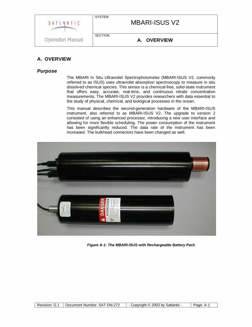
Purpose The MBARI In Situ Ultraviolet Spectrophotometer (MBARI-ISUS V2, commonly referred to as ISUS) uses ultraviolet absorption spectroscopy to measure in situ dissolved chemical species. This sensor is a chemical-free, solid-state instrument that offers easy, accurate, real-time, and continuous nitrate concentration measurements. The MBARI-ISUS V2 provides researchers with data essential to the study of physical, chemical, and biological processes in the ocean.
This manual describes the second-generation hardware of the MBARI-ISUS instrument, also referred to as MBARI-ISUS V2. The upgrade to version 2 consisted of using an enhanced processor, introducing a new user interface and allowing for more flexible scheduling. The power consumption of the instrument has been significantly reduced. The data rate of the instrument has been increased. The bulkhead connectors have been changed as well.
Figure A-1: The MBARI-ISUS with Rechargeable Battery Pack

SYSTEM
MBARI-ISUS V2
SECTION A. OVERVIEW
Revision: G.1 Document Number: SAT-DN-272 - Copyright © 2003 by Satlantic - Page: A-2
Background The MBARI-ISUS V2 was developed by Dr. Kenneth Johnson and Luke Coletti, of the Monterey Bay Aquarium Research Institute (MBARI). For a detailed description of the MBARI prototype system see their paper (Johnson, K., L. Coletti 2002), In situ ultraviolet spectrometry for high resolution and long-term monitoring of nitrate, bromide and bisulfide in the ocean, Deep-Sea Research I, 49, 1291-1305). Satlantic and MBARI collaborated to make the instrument commercially available to researchers. Satlantic has made significant advances in both system hardware and computational software to provide customers with the state-of-the-art in situ spectroscopic analysis.
Using advanced UV absorption techniques, the MBARI-ISUS V2 calculates NO3-
concentration from the seawater absorption spectrum, without the need for chemical manipulation.
The MBARI-ISUS V2 has the stability, sensitivity, and endurance to operate for extended periods of time with low maintenance. It has been successfully deployed in a variety of marine environments and operational modes, including:
Ø Profiling systems – high-resolution nitrate profiles allow insight into nutrient structures.
Ø Fixed platform/moorings – the flexible sampling schedule and internal data storage capacity allow easy integration into a monitoring program.
Ø Towed vehicles – the data is collected by the vehicle’s data acquisition system or logged internally
Features The features of MBARI-ISUS include:
Ø Real-time Nitrate measurements Ø Analog output port for easy integration with CTD (conductivity,
temperature, depth) and other sensors Ø Low power, compact size Ø Fast sample frequency Ø High data precision and accuracy Ø Deep operation Ø Spectral analysis software
SYSTEM
MBARI-ISUS V2
SECTION A. OVERVIEW
Revision: G.1 Document Number: SAT-DN-272 - Copyright © 2003 by Satlantic - Page: A-3
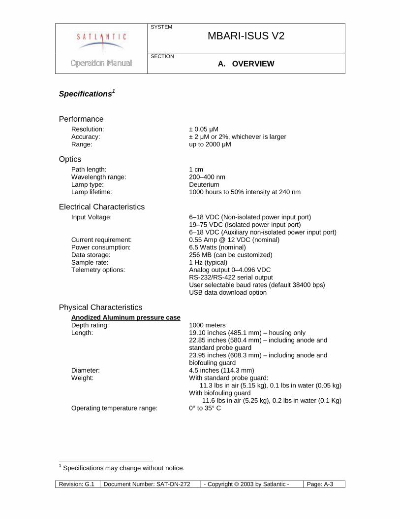
Specifications1
Performance Resolution: ± 0.05 μM Accuracy: ± 2 μM or 2%, whichever is larger Range: up to 2000 μM
Optics Path length: 1 cm Wavelength range: 200–400 nm Lamp type: Deuterium Lamp lifetime: 1000 hours to 50% intensity at 240 nm
Electrical Characteristics Input Voltage: 6–18 VDC (Non-isolated power input port) 19–75 VDC (Isolated power input port) 6–18 VDC (Auxiliary non-isolated power input port) Current requirement: 0.55 Amp @ 12 VDC (nominal) Power consumption: 6.5 Watts (nominal) Data storage: 256 MB (can be customized) Sample rate: 1 Hz (typical) Telemetry options: Analog output 0–4.096 VDC RS-232/RS-422 serial output User selectable baud rates (default 38400 bps) USB data download option
Physical Characteristics Anodized Aluminum pressure case Depth rating: 1000 meters Length: 19.10 inches (485.1 mm) – housing only 22.85 inches (580.4 mm) – including anode and
standard probe guard 23.95 inches (608.3 mm) – including anode and
biofouling guard Diameter: 4.5 inches (114.3 mm) Weight: With standard probe guard: 11.3 lbs in air (5.15 kg), 0.1 lbs in water (0.05 kg) With biofouling guard 11.6 lbs in air (5.25 kg), 0.2 lbs in water (0.1 Kg) Operating temperature range: 0° to 35° C
1 Specifications may change without notice.
SYSTEM
MBARI-ISUS V2
SECTION A. OVERVIEW
Revision: G.1 Document Number: SAT-DN-272 - Copyright © 2003 by Satlantic - Page: A-4
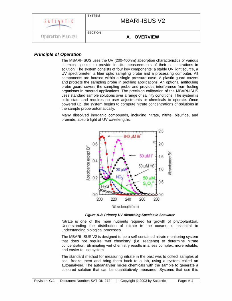
Principle of Operation The MBARI-ISUS uses the UV (200-400nm) absorption characteristics of various chemical species to provide in situ measurements of their concentrations in solution. The system consists of four key components: a stable UV light source, a UV spectrometer, a fiber optic sampling probe and a processing computer. All components are housed within a single pressure case. A plastic guard covers and protects the sampling probe in profiling applications. An optional antifouling probe guard covers the sampling probe and provides interference from fouling organisms in moored applications. The precision calibration of the MBARI-ISUS uses standard sample solutions over a range of salinity conditions. The system is solid state and requires no user adjustments or chemicals to operate. Once powered up, the system begins to compute nitrate concentrations of solutions in the sample probe automatically.
Many dissolved inorganic compounds, including nitrate, nitrite, bisulfide, and bromide, absorb light at UV wavelengths.
Figure A-2: Primary UV Absorbing Species in Seawater
Nitrate is one of the main nutrients required for growth of phytoplankton. Understanding the distribution of nitrate in the oceans is essential to understanding biological processes.
The MBARI-ISUS V2 is designed to be a self-contained nitrate monitoring system that does not require ‘wet chemistry’ (i.e. reagents) to determine nitrate concentration. Eliminating wet chemistry results in a less complex, more reliable, and easier to use system.
The standard method for measuring nitrate in the past was to collect samples at sea, freeze them and bring them back to a lab, using a system called an autoanalyser. The autoanalyser mixes chemicals with the sample to generate a coloured solution that can be quantitatively measured. Systems that use this
SYSTEM
MBARI-ISUS V2
SECTION A. OVERVIEW
Revision: G.1 Document Number: SAT-DN-272 - Copyright © 2003 by Satlantic - Page: A-5
technique in situ are complex because they require mixing limited shelf life reagents and loading these into the instruments.
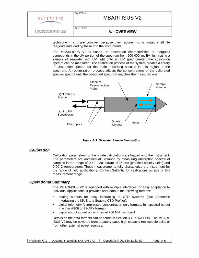
The MBARI-ISUS V2 is based on absorption characteristics of inorganic compounds in the UV portion of the spectrum from 200-400nm. By illuminating a sample of seawater with UV light onto an UV spectrometer, the absorption spectra can be measured. The calibration process of the system creates a library of absorption spectra for the main absorbing species in this region of the spectrum. An optimization process adjusts the concentrations of the calibrated species spectra until the computed spectrum matches the measured one.
Light to UVSpectrograph
Light from UVSource
Fiber optics
TitaniumRetroreflectionProbe
QuartzWindow Mirror
SampleVolume
Figure A-3: Seawater Sample Illumination
Calibration Calibration parameters for the nitrate calculations are loaded onto the instrument. The parameters are obtained at Satlantic by measuring absorption spectra of samples in the range of 0-40 μMol nitrate, 0-35 psu (practical salinity units) and 0-20 C temperature. These measurements fully characterize the instrument for the range of field applications. Contact Satlantic for calibrations outside of this measurement range.
Operational Summary The MBARI-ISUS V2 is equipped with multiple interfaces for easy adaptation to individual applications. It provides user data in the following formats:
• analog outputs for easy interfacing to CTD systems (see Appendix: Interfacing the ISUS to a Seabird CTD Profiler),
• digital telemetry (compressed concentration only formats, full spectral output in either ASCII or BINARY format)
• digital output stored on an internal 256 MB flash card.
Details on the data formats can be found in Section D OPERATION. The MBARI-ISUS V2 may be powered from a battery pack, high capacity replaceable cells, or from other external power sources.
SYSTEM
MBARI-ISUS V2
SECTION A. OVERVIEW
Revision: G.1 Document Number: SAT-DN-272 - Copyright © 2003 by Satlantic - Page: A-6
Major Components The major components of the MBARI-ISUS V2 are the instrument body, the connector end cap, the probe end cap, and the external power source. A computer with a free RS-232 serial port (or a free USB port with a USB to RS-232 converter) is required for configuration and to offload data.
Additionally, it is possible to switch the ISUS instrument from RS-232 connection to USB connection. This feature is useful for downloading large volumes of data.
Please note that in this manual, the term RS-232 implies EIA-232.
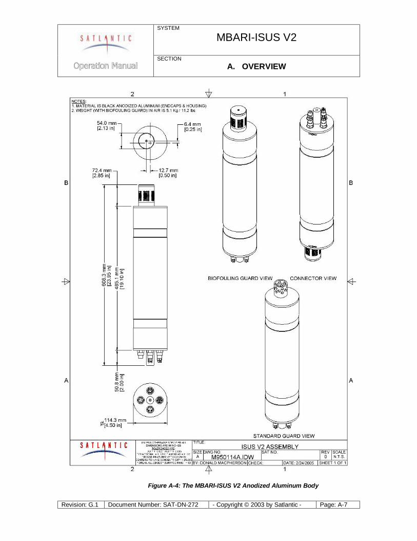
Instrument Body The MBARI-ISUS V2 housing is a standard Satlantic pressure case design, consisting of a corrosion-resistant anodized aluminum tube with two anodized aluminum end caps (see Figure A-4).
SYSTEM
MBARI-ISUS V2
SECTION A. OVERVIEW
Revision: G.1 Document Number: SAT-DN-272 - Copyright © 2003 by Satlantic - Page: A-7
Figure A-4: The MBARI-ISUS V2 Anodized Aluminum Body
SYSTEM
MBARI-ISUS V2
SECTION A. OVERVIEW
Revision: G.1 Document Number: SAT-DN-272 - Copyright © 2003 by Satlantic - Page: A-8
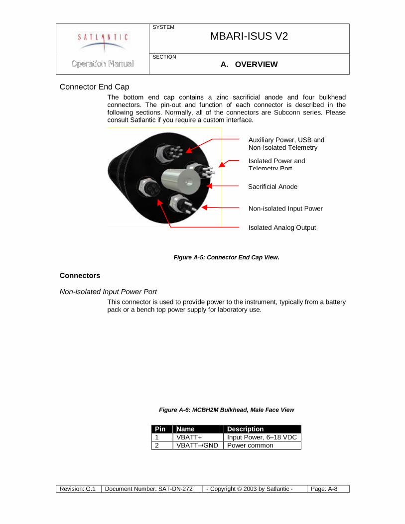
Connector End Cap The bottom end cap contains a zinc sacrificial anode and four bulkhead connectors. The pin-out and function of each connector is described in the following sections. Normally, all of the connectors are Subconn series. Please consult Satlantic if you require a custom interface.
Figure A-5: Connector End Cap View.
Connectors
Non-isolated Input Power Port This connector is used to provide power to the instrument, typically from a battery pack or a bench top power supply for laboratory use.
Figure A-6: MCBH2M Bulkhead, Male Face View
Pin Name Description 1 VBATT+ Input Power, 6–18 VDC 2 VBATT–/GND Power common
Auxiliary Power, USB and Non-Isolated Telemetry
Isolated Power and Telemetry Port
Sacrificial Anode
Non-isolated Input Power
Isolated Analog Output
SYSTEM
MBARI-ISUS V2
SECTION A. OVERVIEW
Revision: G.1 Document Number: SAT-DN-272 - Copyright © 2003 by Satlantic - Page: A-9
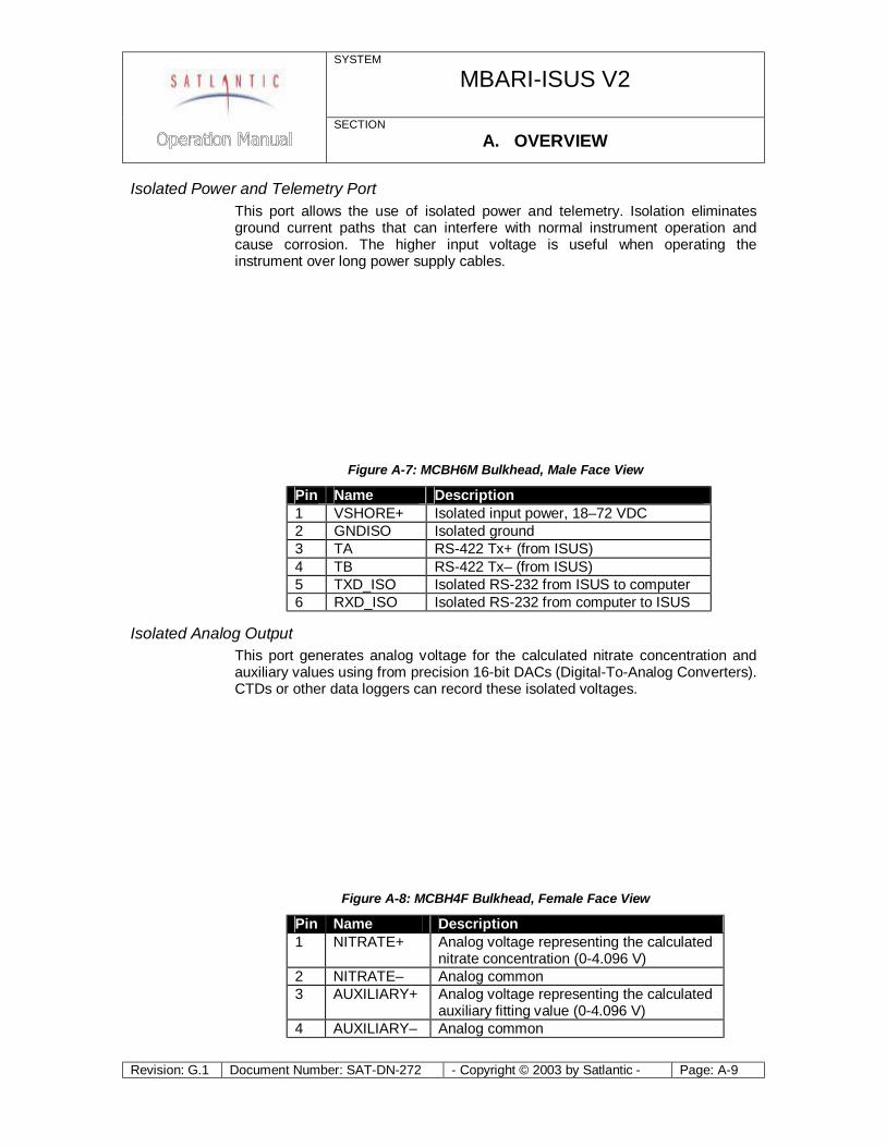
Isolated Power and Telemetry Port This port allows the use of isolated power and telemetry. Isolation eliminates ground current paths that can interfere with normal instrument operation and cause corrosion. The higher input voltage is useful when operating the instrument over long power supply cables.
Figure A-7: MCBH6M Bulkhead, Male Face View
Pin Name Description 1 VSHORE+ Isolated input power, 18–72 VDC 2 GNDISO Isolated ground 3 TA RS-422 Tx+ (from ISUS) 4 TB RS-422 Tx– (from ISUS) 5 TXD_ISO Isolated RS-232 from ISUS to computer 6 RXD_ISO Isolated RS-232 from computer to ISUS
Isolated Analog Output This port generates analog voltage for the calculated nitrate concentration and auxiliary values using from precision 16-bit DACs (Digital-To-Analog Converters). CTDs or other data loggers can record these isolated voltages.
Figure A-8: MCBH4F Bulkhead, Female Face View
Pin Name Description 1 NITRATE+ Analog voltage representing the calculated
nitrate concentration (0-4.096 V) 2 NITRATE– Analog common 3 AUXILIARY+ Analog voltage representing the calculated
auxiliary fitting value (0-4.096 V) 4 AUXILIARY– Analog common
SYSTEM
MBARI-ISUS V2
SECTION A. OVERVIEW
Revision: G.1 Document Number: SAT-DN-272 - Copyright © 2003 by Satlantic - Page: A-10
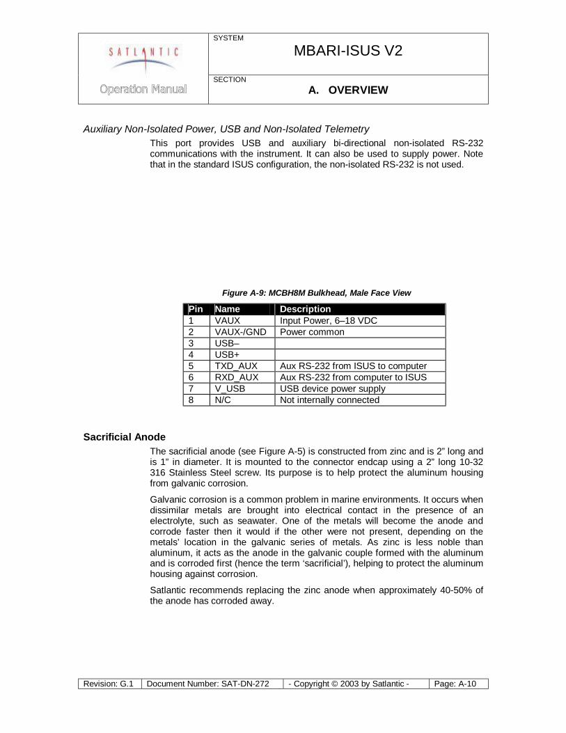
Auxiliary Non-Isolated Power, USB and Non-Isolated Telemetry This port provides USB and auxiliary bi-directional non-isolated RS-232 communications with the instrument. It can also be used to supply power. Note that in the standard ISUS configuration, the non-isolated RS-232 is not used.
Figure A-9: MCBH8M Bulkhead, Male Face View
Pin Name Description 1 VAUX Input Power, 6–18 VDC 2 VAUX-/GND Power common 3 USB– 4 USB+ 5 TXD_AUX Aux RS-232 from ISUS to computer 6 RXD_AUX Aux RS-232 from computer to ISUS 7 V_USB USB device power supply 8 N/C Not internally connected
Sacrificial Anode The sacrificial anode (see Figure A-5) is constructed from zinc and is 2” long and is 1” in diameter. It is mounted to the connector endcap using a 2” long 10-32 316 Stainless Steel screw. Its purpose is to help protect the aluminum housing from galvanic corrosion.
Galvanic corrosion is a common problem in marine environments. It occurs when dissimilar metals are brought into electrical contact in the presence of an electrolyte, such as seawater. One of the metals will become the anode and corrode faster then it would if the other were not present, depending on the metals’ location in the galvanic series of metals. As zinc is less noble than aluminum, it acts as the anode in the galvanic couple formed with the aluminum and is corroded first (hence the term ‘sacrificial’), helping to protect the aluminum housing against corrosion.
Satlantic recommends replacing the zinc anode when approximately 40-50% of the anode has corroded away.

SYSTEM
MBARI-ISUS V2
SECTION A. OVERVIEW
Revision: G.1 Document Number: SAT-DN-272 - Copyright © 2003 by Satlantic - Page: A-11
Power Supply The MBARI-ISUS V2 has a flexible power supply system that allows it to be powered from a number of sources, depending on the application. Normally, a 12 V battery pack is used.
Power can be supplied on 3 of the bulkhead connectors. They are connected internally using diodes, preventing the possibility of shorting supplies. If power is available on more than one bulkhead, the one with the highest voltage will supply the ISUS.
The ISUS normally draws 0.55 A at 12 V while operating. Previous versions of the ISUS required a significant current surge when enabling the UV-lamp. However, this surge is virtually eliminated in the new design. A minimum supply of 1 A at 12 V is adequate to turn on the ISUS.
The instrument will detect a situation of insufficient power, and commence a safe shutdown procedure. If this procedure is entered during the initial stages of the operation, the power supply was probably too weak. In this situation, it is recommended to disconnect the instrument, and restart using a stronger power supply.
Probe End Cap The top or probe end cap consists of a retro-reflection probe held in place by the probe retaining nut. The retaining nut is threaded on the outside, allowing a protecting probe guard or biofouling guard to be easily installed
Figure A-10: Probe Endcap
Probe Retaining Nut
Retro-reflection Probe
Endcap
SYSTEM
MBARI-ISUS V2
SECTION A. OVERVIEW
Revision: G.1 Document Number: SAT-DN-272 - Copyright © 2003 by Satlantic - Page: A-12
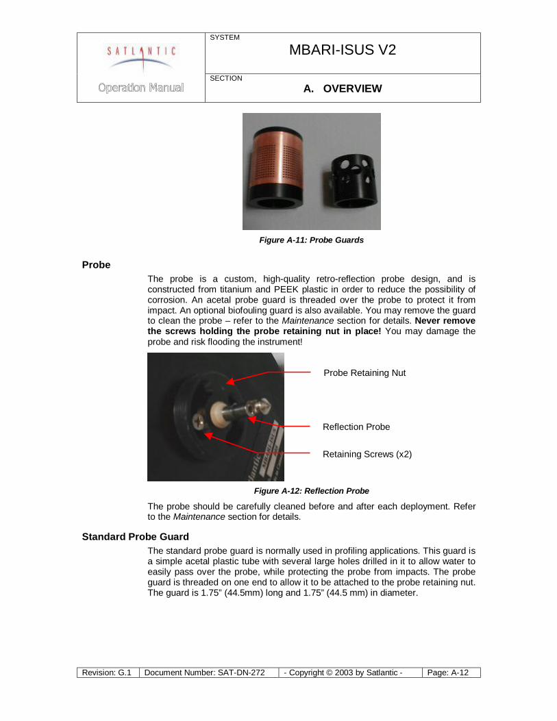
Figure A-11: Probe Guards
Probe The probe is a custom, high-quality retro-reflection probe design, and is constructed from titanium and PEEK plastic in order to reduce the possibility of corrosion. An acetal probe guard is threaded over the probe to protect it from impact. An optional biofouling guard is also available. You may remove the guard to clean the probe – refer to the Maintenance section for details. Never remove the screws holding the probe retaining nut in place! You may damage the probe and risk flooding the instrument!
Figure A-12: Reflection Probe
The probe should be carefully cleaned before and after each deployment. Refer to the Maintenance section for details.
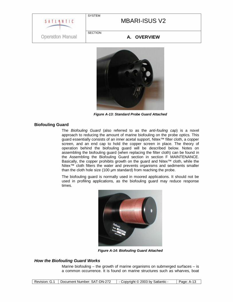
Standard Probe Guard The standard probe guard is normally used in profiling applications. This guard is a simple acetal plastic tube with several large holes drilled in it to allow water to easily pass over the probe, while protecting the probe from impacts. The probe guard is threaded on one end to allow it to be attached to the probe retaining nut. The guard is 1.75” (44.5mm) long and 1.75” (44.5 mm) in diameter.
Retaining Screws (x2)
Reflection Probe
Probe Retaining Nut
SYSTEM
MBARI-ISUS V2
SECTION A. OVERVIEW
Revision: G.1 Document Number: SAT-DN-272 - Copyright © 2003 by Satlantic - Page: A-13
Figure A-13: Standard Probe Guard Attached
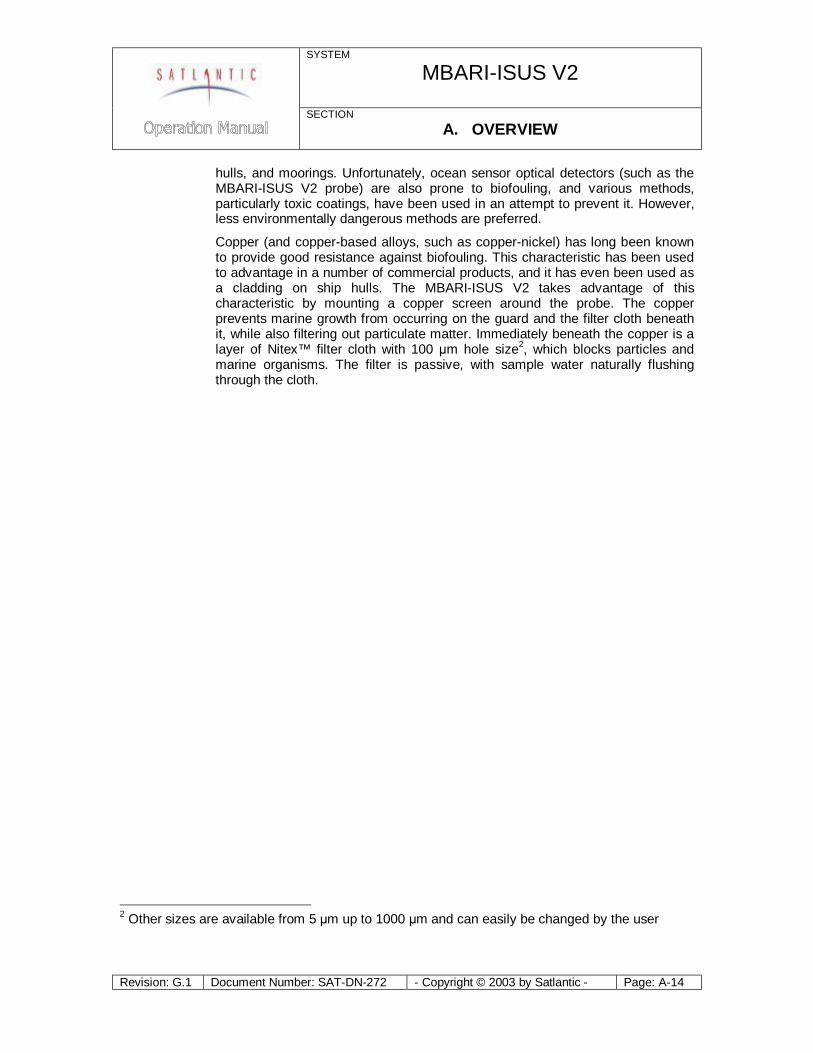
Biofouling Guard The Biofouling Guard (also referred to as the anti-fouling cap) is a novel approach to reducing the amount of marine biofouling on the probe optics. This guard essentially consists of an inner acetal support, Nitex™ filter cloth, a copper screen, and an end cap to hold the copper screen in place. The theory of operation behind the biofouling guard will be described below. Notes on assembling the biofouling guard (when replacing the filter cloth) can be found in the Assembling the Biofouling Guard section in section F MAINTENANCE. Basically, the copper prohibits growth on the guard and Nitex™ cloth, while the Nitex™ cloth filters the water and prevents organisms and sediments smaller than the cloth hole size (100 μm standard) from reaching the probe.
The biofouling guard is normally used in moored applications. It should not be used in profiling applications, as the biofouling guard may reduce response times.
Figure A-14: Biofouling Guard Attached
How the Biofouling Guard Works Marine biofouling – the growth of marine organisms on submerged surfaces – is a common occurrence. It is found on marine structures such as wharves, boat
SYSTEM
MBARI-ISUS V2
SECTION A. OVERVIEW
Revision: G.1 Document Number: SAT-DN-272 - Copyright © 2003 by Satlantic - Page: A-14
hulls, and moorings. Unfortunately, ocean sensor optical detectors (such as the MBARI-ISUS V2 probe) are also prone to biofouling, and various methods, particularly toxic coatings, have been used in an attempt to prevent it. However, less environmentally dangerous methods are preferred.
Copper (and copper-based alloys, such as copper-nickel) has long been known to provide good resistance against biofouling. This characteristic has been used to advantage in a number of commercial products, and it has even been used as a cladding on ship hulls. The MBARI-ISUS V2 takes advantage of this characteristic by mounting a copper screen around the probe. The copper prevents marine growth from occurring on the guard and the filter cloth beneath it, while also filtering out particulate matter. Immediately beneath the copper is a layer of Nitex™ filter cloth with 100 μm hole size2, which blocks particles and marine organisms. The filter is passive, with sample water naturally flushing through the cloth.
2 Other sizes are available from 5 μm up to 1000 μm and can easily be changed by the user
SYSTEM
MBARI-ISUS V2
SECTION B. SAFETY & HAZARDS
Revision: G.1 Document Number: SAT-DN-272 - Copyright © 2003 by Satlantic - Page: B-1
B. SAFETY & HAZARDS
Personal Safety
WARNING!
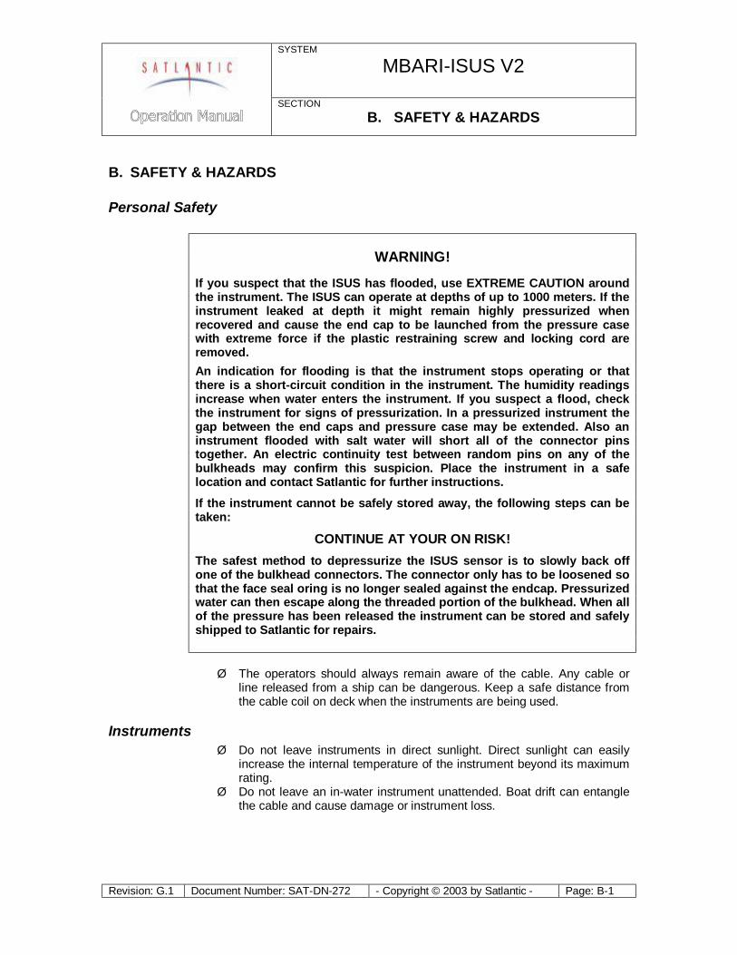
If you suspect that the ISUS has flooded, use EXTREME CAUTION around the instrument. The ISUS can operate at depths of up to 1000 meters. If the instrument leaked at depth it might remain highly pressurized when recovered and cause the end cap to be launched from the pressure case with extreme force if the plastic restraining screw and locking cord are removed. An indication for flooding is that the instrument stops operating or that there is a short-circuit condition in the instrument. The humidity readings increase when water enters the instrument. If you suspect a flood, check the instrument for signs of pressurization. In a pressurized instrument the gap between the end caps and pressure case may be extended. Also an instrument flooded with salt water will short all of the connector pins together. An electric continuity test between random pins on any of the bulkheads may confirm this suspicion. Place the instrument in a safe location and contact Satlantic for further instructions.
If the instrument cannot be safely stored away, the following steps can be taken:
CONTINUE AT YOUR ON RISK! The safest method to depressurize the ISUS sensor is to slowly back off one of the bulkhead connectors. The connector only has to be loosened so that the face seal oring is no longer sealed against the endcap. Pressurized water can then escape along the threaded portion of the bulkhead. When all of the pressure has been released the instrument can be stored and safely shipped to Satlantic for repairs. Ø The operators should always remain aware of the cable. Any cable or
line released from a ship can be dangerous. Keep a safe distance from the cable coil on deck when the instruments are being used.
Instruments Ø Do not leave instruments in direct sunlight. Direct sunlight can easily
increase the internal temperature of the instrument beyond its maximum rating.
Ø Do not leave an in-water instrument unattended. Boat drift can entangle the cable and cause damage or instrument loss.
SYSTEM
MBARI-ISUS V2
SECTION B. SAFETY & HAZARDS
Revision: G.1 Document Number: SAT-DN-272 - Copyright © 2003 by Satlantic - Page: B-2
Cable Ø To prevent damage to the conductors within the Kevlar™ strength
member (if present), ensure that the cables are not pinched or bent to a radius of less than 18 cm.
Connections Ø Handle electrical terminations carefully, as they are not designed to
withstand strain. Disconnect the cables from the components by pulling on the connector heads and not the cables. Do not twist the connector while pulling, as this will damage the connector pins.
Ø Do not use petroleum-based lubricants on Subconn® connectors. Connectors should be free of dirt and lightly lubricated before mating. Satlantic recommends using DC-111 silicone grease (made by Dow-Corning®) on the male pins prior to connection.
Troubleshooting Ø While checking voltages with a multimeter, use extreme care to avoid
shorting the probe leads. A shorted power supply or battery can output many amperes of current, potentially harming the user, starting fires, or damaging equipment.
Recovery Ø Remember never to grab the electrical portion of the instrument cable
during recovery. This can cause damage to the bulkhead connector and the underwater splice.
Ø Be sure to rinse seawater from the instrument with fresh water prior to storage. Corrosion resulting from failure to do so is not covered under warranty.
SYSTEM
MBARI-ISUS V2
SECTION C. START UP
Revision: G.1 Document Number: SAT-DN-272 - Copyright © 2003 by Satlantic - Page: C-1
C. START UP
Preparation The MBARI-ISUS V2 can be configured to operate in CONTINUOUS, FIXEDTIME, TRIGGERED, SCHEDULED, and BENCHTOP modes, as outlined in the Operation section. Generally, requirements for operation are the same for all modes.
You will need the following items:
§ DC power source: Either 6–18 VDC (12–15V preferred) or 18-72 VDC with a minimum 1 A current.
§ Computer with a free serial communications port for telemetry acquisition or later data download.
§ Data acquisition and processing software compliant with the Satlantic Data Format Standard (SatView and SatCon normally provided)
§ The instrument SIP file (provided)
If you are not using your instrument in an embedded system, or you do not have your own data acquisition software, you may use the software provided by Satlantic. Two applications3, SatView and SatCon, are available to you for any PC running Windows®4 95/98/NT/2000/XP. Both applications are compliant with the Satlantic Data Format Standard. SatView is a data acquisition and real-time display application. SatCon is a post processing application for telemetry logged with SatView.
The ISUS normally logs data internally as well, so a data acquisition device is not required. However, Satlantic’s SatView software allows you to view the data in real time, while SatCon enables you to easily separate light and dark frames. ISUS specific processing software is provided in the ISUSPro software package.
Also note that it is not necessary to use the software mentioned above to log the instrument telemetry. A properly configured terminal emulator can serve this purpose. In any case, there are a few standard communications settings needed for any computer application communicating with the instrument. All serial transmissions use 1 start bit, 8 data bits, 1 stop bit, and no parity. No flow control of any kind is used. Make sure that your software is configured with the baud rate specified for your instrument. Initially, the telemetry baud rate is 38400 bps.
In preparation for assembly, the MBARI-ISUS V2 components should be checked against the packing list to ensure that all required items are included. The dummy connectors should be removed and stored so that they can be replaced after the instrument is recovered. The instrument packing should be retained and reused to prevent instrument damage during transport.
Additionally, lubrication for the male pins prior to connection is required. We recommend DC-111 silicone grease (made by Dow-Corning). Do not use a petroleum base lubricant.
3 For more information on these applications, refer to the user's manuals distributed with the software. 4 Windows is a registered trademark of Microsoft Corporation.
SYSTEM
MBARI-ISUS V2
SECTION C. START UP
Revision: G.1 Document Number: SAT-DN-272 - Copyright © 2003 by Satlantic - Page: C-2
Connect the Cables When connecting the cables, proper alignment on the connector pins is critical to avoid damage. Connectors should be inspected to ensure they are free of dirt and then lightly lubricated before connecting. Visually ensure that the pins on the male connectors are properly aligned with (and partially seated into) the sockets on their female counterparts before pushing them together. Finally, ensure that the locking sleeve is securely fastened after connection.
Connect the instrument body, the computer and the battery to the deck unit, as follows.
1. Mount the ISUS to its deployment frame. 2. Mount the battery pack, if present, to the deployment frame. 3. Connect the configuration cable to the ISUS and a spare PC serial port. 4. Start a terminal emulator with the proper settings on the PC, and connect to
the port. 5. Connect the power source to the ISUS.
Once the ISUS has been connected and power has been applied, an initialization sequence will begin to ready the device for normal operation. The ISUS will output status messages as it goes through the initialization steps. These will be displayed in the terminal emulator and are also logged instrument internally for later reference.

SYSTEM
MBARI-ISUS V2
SECTION C. START UP
Revision: G.1 Document Number: SAT-DN-272 - Copyright © 2003 by Satlantic - Page: C-3
Telemetry Acquisition Using SatView If you are using the instrument with real-time telemetry, it is possible to monitor the data in Satlantic’s SatView software.
To view the ISUS data in SatView, go to the “Setup Menu” on the Toolbar, and select “Add instrument”. Browse to find the appropriate .SIP file (included on the instrument CD) and load it into the “From Instrument Package” box. Once the .SIP file is loaded, go to the main SatView window and set the COM port. For further instructions on how to use SatView, please refer to the SatView user manual.
Below is an example of a data acquisition. The top left window is the connection interface, and at the top right auxiliary data (nitrate concentration, temperatures, power stability) are shown. At the bottom, the numerical values and a graph of the UV-spectrum are displayed.
Figure C-1: SatView real-time display.
SYSTEM
MBARI-ISUS V2
SECTION C. START UP
Revision: G.1 Document Number: SAT-DN-272 - Copyright © 2003 by Satlantic - Page: C-4
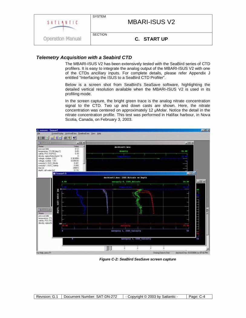
Telemetry Acquisition with a Seabird CTD The MBARI-ISUS V2 has been extensively tested with the SeaBird series of CTD profilers. It is easy to integrate the analog output of the MBARI-ISUS V2 with one of the CTDs ancillary inputs. For complete details, please refer Appendix J entitled “Interfacing the ISUS to a SeaBird CTD Profiler”.
Below is a screen shot from SeaBird’s SeaSave software, highlighting the detailed vertical resolution available when the MBARI-ISUS V2 is used in its profiling mode.
In the screen capture, the bright green trace is the analog nitrate concentration signal to the CTD. Two up and down casts are shown. Here, the nitrate concentration was centered on approximately 12 μMolar. Notice the detail in the nitrate concentration profile. This test was performed in Halifax harbour, in Nova Scotia, Canada, on February 3, 2003.
Figure C-2: SeaBird SeaSave screen capture
SYSTEM
MBARI-ISUS V2
SECTION C. START UP
Revision: G.1 Document Number: SAT-DN-272 - Copyright © 2003 by Satlantic - Page: C-5
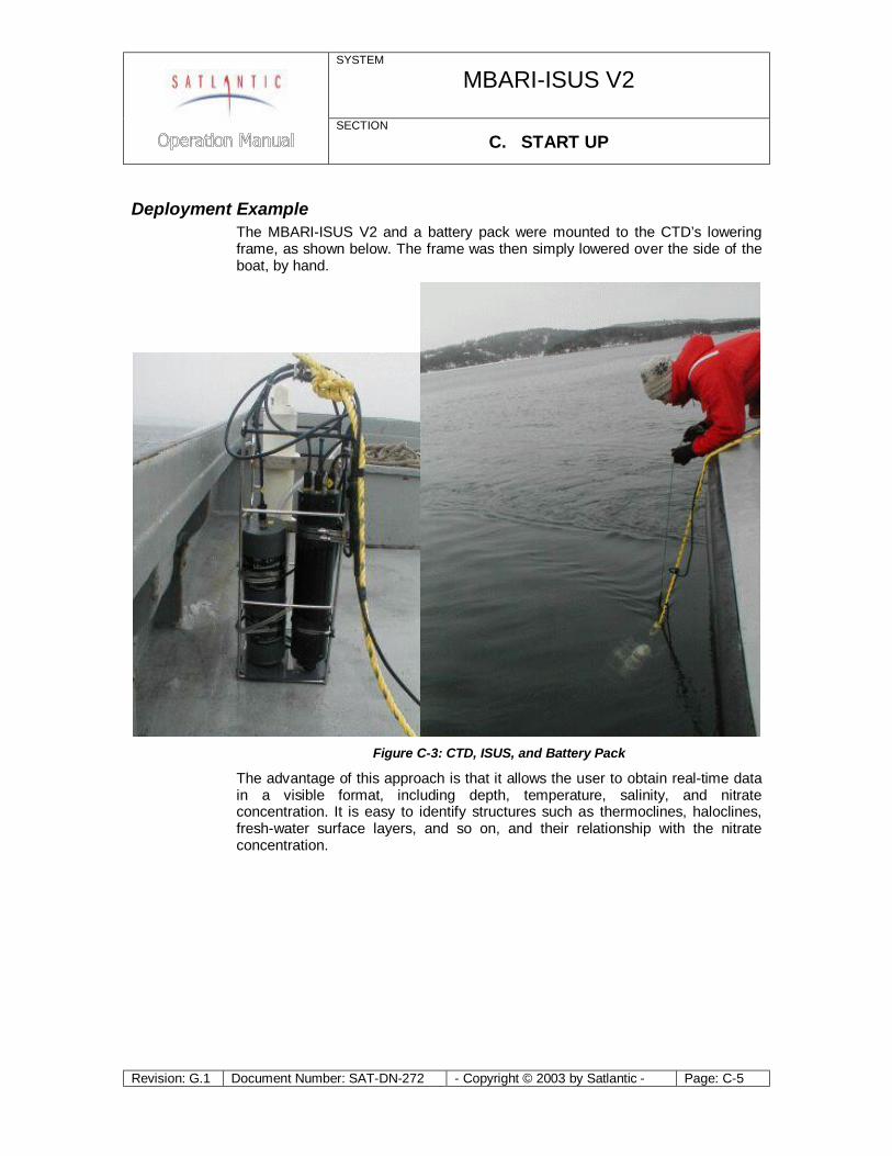
Deployment Example The MBARI-ISUS V2 and a battery pack were mounted to the CTD’s lowering frame, as shown below. The frame was then simply lowered over the side of the boat, by hand.
Figure C-3: CTD, ISUS, and Battery Pack
The advantage of this approach is that it allows the user to obtain real-time data in a visible format, including depth, temperature, salinity, and nitrate concentration. It is easy to identify structures such as thermoclines, haloclines, fresh-water surface layers, and so on, and their relationship with the nitrate concentration.
SYSTEM
MBARI-ISUS V2
SECTION D. OPERATION
Revision: G.1 Document Number: SAT-DN-272 - Copyright © 2003 by Satlantic - Page: D-1
D. OPERATION
Operating Modes The ISUS has been designed with several user-selectable operating modes: CONTINUOUS, FIXEDTIME, SCHEDULED, BENCHTOP and TRIGGERED. Future ISUS units may include additional operating modes not described here.
The operating mode is retained in the ISUS’s non-volatile memory. At power-up, the operating mode is checked and the necessary initialization actions are performed. If the user changes the operating mode, power will have to be removed and then reapplied (after approximately 1 minute, in order to discharge the instrument internal power protection charge). The operating mode can be changed from the setup menu (explained below).
Continuous In continuous or “profiling” mode the instrument begins acquiring data after a configurable number of seconds (initially 15) and stops when power is removed.
Each acquisition cycle starts a new log file on the ISUS internal flash-disk with the name DIVEnnn.DAT, where ‘nnn’ is incremented with each cycle; ‘nnn’ is referred to as the deployment counter and is saved in non-volatile memory. Thus, each profile is logged to a separate file.
When connected via a terminal emulator, the user will see a per-second counter before the start of the acquisition. The ‘G’ (go) command bypasses the start-up delay, the ‘M’ command provides access to menus for configuration, setup and data download. After exiting the menu the instrument will return to the start-up counter. After the instrument has started acquiring data, the ‘S’ (stop) command (multiple key presses may be necessary) will return the instrument into the start-up loop.
Fixed Time Fixed time mode is almost identical to continuous mode. The only exception is that the instrument stops acquiring data after a user configurable period and enters low power mode. The user can then choose to enter the menu.
Scheduled Scheduled mode is typically used in moored applications. The ISUS can be scheduled to periodically wake up, measure, and record data. Between events, the instrument enters a very low-power sleep state to conserve power.
The schedule is defined in the SCHEDULE.TXT file, which has to be uploaded onto the instrument prior to deployment. Initially, the instrument is scheduled to power the instrument once every 60 minutes, and acquires 20 seconds worth of data every time. The ISUSSchedule program is used to create a custom SCHEDULE.TXT file.
The scheduling file contains three types of command lines, for example: 16:30:00 Power +ISUS
SYSTEM
MBARI-ISUS V2
SECTION D. OPERATION
Revision: G.1 Document Number: SAT-DN-272 - Copyright © 2003 by Satlantic - Page: D-2
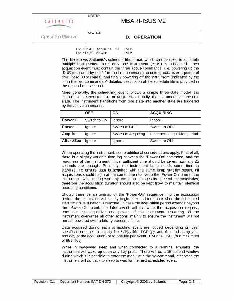
16:30:45 Acquire 30 ISUS 16:31:20 Power -ISUS
The file follows Satlantic’s schedule file format, which can be used to schedule multiple instruments. Here, only one instrument (ISUS) is scheduled. Each acquisition event must contain the three above commands, i. e. powering up the ISUS (indicated by the ‘+’ in the first command), acquiring data over a period of time (here 30 seconds), and finally powering off the instrument (indicated by the ‘-‘ in the last command). A detailed description of the schedule file is provided in the appendix in section I.
More generally, the scheduling event follows a simple three-state model: the instrument is either OFF, ON, or ACQUIRING. Initially, the instrument is in the OFF state. The instrument transitions from one state into another state are triggered by the above commands.
OFF ON ACQUIRING
Power + Switch to ON Ignore Ignore
Power – Ignore Switch to OFF Switch to OFF
Acquire Ignore Switch to Acquiring Increment acquisition period
After #Sec Ignore Ignore Switch to ON
When operating the instrument, some additional considerations apply. First of all, there is a slightly variable time lag between the ‘Power-On’ command, and the readiness of the instrument. Thus, sufficient time should be given, normally 25 seconds are enough. Secondly, the instrument lamp needs some time to stabilize. To ensure data is acquired with the same lamp stability status, all acquisitions should begin at the same time relative to the ‘Power-On’ time of the instrument. Also, during warm-up the lamp changes its spectral characteristics; therefore the acquisition duration should also be kept fixed to maintain identical operating conditions.
Should there be an overlap of the ‘Power-On’ sequence into the acquisition period, the acquisition will simply begin later and terminate when the scheduled start time plus duration is reached. In case the acquisition period extends beyond the ‘Power-Off’ point, the later event will overwrite the acquisition request, terminate the acquisition and power off the instrument. Powering off the instrument overwrites all other actions, mainly to ensure the instrument will not remain powered over arbitrary periods of time.
Data acquired during each scheduling event are logged depending on user specification either to a daily file SCHyyddd.DAT (yy and ddd indicating year and day of the acquisition) or to one file per event DIVEnnn.DAT (to a maximum of 999 files)
While in low-power sleep and when connected to a terminal emulator, the instrument will wake up upon any key press. There will be a 15 second window during which it is possible to enter the menu with the ‘M’ command, otherwise the instrument will go back to sleep to wait for the next scheduled event.
SYSTEM
MBARI-ISUS V2
SECTION D. OPERATION
Revision: G.1 Document Number: SAT-DN-272 - Copyright © 2003 by Satlantic - Page: D-3
After a scheduling deployment, the message and error log files should be consulted. Problems occurring during operation are recorded in these files. (Refer to the Fitting Setup Menu Section for details.)
Benchtop Benchtop mode is basically identical to scheduled mode. The only difference is that the instrument assumes that the power supply will be steady, and thus waive some precautionary measures. When operating in Benchtop mode, the instrument acquisition must be interrupted and the instrument must be in the user interface menu before power can be disconnected.
Triggered Triggered mode brings the instrument after initialization into a low power sleep mode. An external controller can trigger an acquisition by first sending an arbitrary character and then the character ‘g’ (for go) over the serial RS-232 line. There must be a time delay between the first and second character of between 1 and 4 seconds. The ISUS instrument will wake up, and acquire data.
The acquisition can be terminated by either sending a termination key (character ‘s’ for stop) or by choosing a fixed time for each acquisition. Triggered mode is similar to scheduled mode in that the instrument will acquire data intermittently.

SYSTEM
MBARI-ISUS V2
SECTION D. OPERATION
Revision: G.1 Document Number: SAT-DN-272 - Copyright © 2003 by Satlantic - Page: D-4
Frame Output Modes The frame format for the ISUS, as with all Satlantic instrumentation, follows the Satlantic Data Format Standard5. This standard defines how Satlantic frames are composed and interpreted. For every sample taken, the instrument will compose one frame of data, save this frame to flash disk and transmit it via serial telemetry. The information contained in the frame will depend on the frame output mode of the instrument. The instrument’s telemetry definition file (also called calibration file) defines the format of the frame.
Three frame output modes are available in the ISUS: Concentration ASCII, Full ASCII (default) and Full BINARY. Full mode provides all available information to the user, at the expense of increased frame and log file size. Concentration mode provides a greatly reduced frame, containing only a timestamp, the nitrate concentration and auxiliary fitting results as calculated by the ISUS. The frame format for each mode is given in the table below. Please note that either frame output mode may be used regardless of the operation mode of the instrument.
For ASCII frames, separate fields are comma-delimited. The frame size may vary, but a maximum size of each field is given. Satlantic’s data logging software (SatView) supports such variable length frames, and as such the size of each field may change without affecting the calibration file. If integrating the ISUS with foreign data-logging devices, it will be necessary to rely on the comma delimiters to distinguish data fields.
In BINARY frames, separate fields are of a fixed length, and therefore do not require delimiters. This and the BINARY inherent compact representation of data leads to a reduction of the frame size by a factor of nearly 3. BINARY frames have to be converted to ASCII (e.g using SatCon) data for further processing.
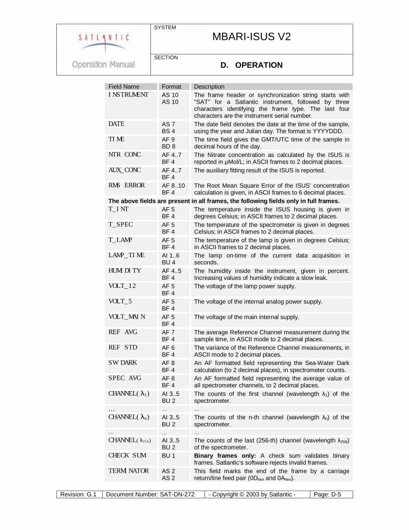
The following table lists all fields occurring in ISUS frames, and explains their meaning. The format of the fields and their size are given, first for ASCII frames, then for BINARY frames. Occurring formats are ASCII Integer (AI), ASCII Float (AF), ASCII String (AS), Binary Signed Integer (BS), Binary Unsigned Integer (BU), Binary Float (BF) and Binary double precision float (BD). Binary fields have fixed sizes, ASCII fields may have fixed or variable sizes. Please refer to the Satlantic Data Format Standard for more details on these data types.
5 For more information on Satlantic telemetry format, refer to the Instrument File Standard document available from Satlantic
SYSTEM
MBARI-ISUS V2
SECTION D. OPERATION
Revision: G.1 Document Number: SAT-DN-272 - Copyright © 2003 by Satlantic - Page: D-5
Field Name Format Description INSTRUMENT AS 10
AS 10 The frame header or synchronization string starts with "SAT" for a Satlantic instrument, followed by three characters identifying the frame type. The last four characters are the instrument serial number.
DATE AS 7 BS 4
The date field denotes the date at the time of the sample, using the year and Julian day. The format is YYYYDDD.
TIME AF 9 BD 8
The time field gives the GMT/UTC time of the sample in decimal hours of the day.
NTR CONC AF 4..7 BF 4
The Nitrate concentration as calculated by the ISUS is reported in μMol/L; in ASCII frames to 2 decimal places.
AUX_CONC AF 4..7 BF 4
The auxiliary fitting result of the ISUS is reported.
RMS ERROR AF 8..10 BF 4
The Root Mean Square Error of the ISUS’ concentration calculation is given, in ASCII frames to 6 decimal places.
The above fields are present in all frames, the following fields only in full frames. T_INT AF 5
BF 4 The temperature inside the ISUS housing is given in degrees Celsius; in ASCII frames to 2 decimal places.
T_SPEC AF 5 BF 4
The temperature of the spectrometer is given in degrees Celsius; in ASCII frames to 2 decimal places.
T_LAMP AF 5 BF 4
The temperature of the lamp is given in degrees Celsius; in ASCII frames to 2 decimal places.
LAMP_TIME AI 1..6 BU 4
The lamp on-time of the current data acquisition in seconds.
HUMIDITY AF 4..5 BF 4
The humidity inside the instrument, given in percent. Increasing values of humidity indicate a slow leak.
VOLT_12 AF 5 BF 4
The voltage of the lamp power supply.
VOLT_5 AF 5 BF 4
The voltage of the internal analog power supply.
VOLT_MAIN AF 5 BF 4
The voltage of the main internal supply.
REF AVG AF 7 BF 4
The average Reference Channel measurement during the sample time, in ASCII mode to 2 decimal places.
REF STD AF 6 BF 4
The variance of the Reference Channel measurements, in ASCII mode to 2 decimal places.
SW DARK AF 8 BF 4
An AF formatted field representing the Sea-Water Dark calculation (to 2 decimal places), in spectrometer counts.
SPEC AVG AF 8 BF 4
An AF formatted field representing the average value of all spectrometer channels, to 2 decimal places.
CHANNEL(λ1) AI 3..5 BU 2
The counts of the first channel (wavelength λ1) of the spectrometer.
… … … CHANNEL(λn) AI 3..5
BU 2 The counts of the n-th channel (wavelength λn) of the spectrometer.
… … … CHANNEL(λ256) AI 3..5
BU 2 The counts of the last (256-th) channel (wavelength λ256) of the spectrometer.
CHECK SUM BU 1 Binary frames only: A check sum validates binary frames. Satlantic’s software rejects invalid frames.
TERMINATOR AS 2 AS 2
This field marks the end of the frame by a carriage return/line feed pair (0Dhex and 0Ahex).
SYSTEM
MBARI-ISUS V2
SECTION D. OPERATION
Revision: G.1 Document Number: SAT-DN-272 - Copyright © 2003 by Satlantic - Page: D-6
Depending on the frame type, the sizes of the frames (for ASCII frames including the delimiters) are:
ASCII Concentration Frame 57 bytes (maximum) ASCII Full Frame 1675 bytes (maximum) Binary Full Frame 595 bytes (fixed)
For a flash disk size of 256 MB, this translates to approximately 4,500,000 ASCII Concentration frames, 155,000 ASCII Full frames, or 440,000 Binary Full frames. With an acquisition rate of one frame per second, an acquisition period of 52 days (ASCII Concentration frame), 43.5 hours (ASCII Full frame) or 122 hours (Binary Full frame) can be stored on the flash disk. Larger disk sizes are available upon request.
The instrument is normally configured to periodically generate dark spectra to correct for thermal noise. This is achieved by closing an on-board shutter over the UV light source before sampling. To distinguish between Light and Dark frames, the instrument uses different frame headers. This allows any telemetry acquisition system to distinguish between sensor readings taken with the shutter opened and closed.
The different frames are distinguished by their header string: following the three letter ‘SAT’ identifier is a three letter frame identifier: The first letter is for ISUS frames always a ‘N’, indicating that the ISUS is an Nitrate measuring instrument. The second letter indicates the shutter state of that frame (‘L’ for Light frame, ‘D’ for Dark frame) and the third letter indicates the frame type (‘C’ for ASCII Concentration Frame, ‘F’ for ASCII Full Frame, and ‘B’ for Binary Full Frame).
Frame Header Explanation of frame header
SATNLC SATlantic Nitrate Light Concentration frame
SATNDC SATlantic Nitrate Dark Concentration frame
SATNLF SATlantic Nitrate Light Full ASCII frame
SATNDF SATlantic Nitrate Dark Full ASCII frame
SATNLB SATlantic Nitrate Light full Binary frame
SATNDB SATlantic Nitrate Dark full Binary frame
SYSTEM
MBARI-ISUS V2
SECTION D. OPERATION
Revision: G.1 Document Number: SAT-DN-272 - Copyright © 2003 by Satlantic - Page: D-7
Communicating with the ISUS The ISUS menu is accessed via its serial communication interface (SCI). Thus, the instrument must be connected to a power supply and via its isolated telemetry port (6-pin) to a computer capable of emulating a serial terminal connection. The HyperTerm software is a frequently used terminal emulator, but other programs work equally well. For a guide on how to use HyperTerm, please refer to the guide in the appendix.
The ISUS always uses 8 data bits, no parity, no flow control, and one stop bit for its communication. The data rate can be adjusted by the user, and is initially set to 38 400 baud.
How to reach the root menu When turned on, the instrument will first send messages over its serial communication port. Then it waits for the operator to sent an interrupt (‘M’-key) for entering the root menu.
If no interrupt is received (the normal mode of operation), data acquisition will begin (CONTINUOUS, FIXEDTIME mode) or operation may be suspended to resume up at a later time (SCHEDULED, BENCHTOP, TRIGGERED mode). The ‘S’-key interrupts acquisition, and a further ‘M’ key will bring the instrument into the menu. An arbitrary key interrupts suspension in SCHEDULED mode, after which the ‘M’-key key will bring the instrument into the root menu.
Menus The root menu gives access to the configuration, setup, file, info and USB menus.
In any menu, simply type H<Enter> to display the list of available commands. To exit the current menu, press Q<Enter>. The menu interface does not distinguish between upper and lower case letters.
Each menu has a distinct prompt indicating which menu you are currently in. For instance, the prompt for the main menu is ISUS>.
The menus serve a number of purposes: to view and optionally modify a current instrument setting, or to move data to or from the instrument.
Configuration Menu The Configuration Menu provides access to basic instrument settings. It is identified by the ISUS_CONFIG> prompt. Commands are [S]how Configuration [B]audrate [D]eployment Counter
A typical configuration is: Instrument type: ISUS Serial No.: 101 Baudrate: 38400 Deployment Cntr: 16
SYSTEM
MBARI-ISUS V2
SECTION D. OPERATION
Revision: G.1 Document Number: SAT-DN-272 - Copyright © 2003 by Satlantic - Page: D-8
Only the baud rate and the deployment counter can be modified.
Baudrate The data rate for the telemetry channel may be one of 9600, 19200 or 38400 bps. To operate at a new baud rate, it is necessary to remove power from the instrument, and restart it.
Deployment Counter The deployment counter determines the next file name to use for internal logging of data: DIVEnnn.DAT, where nnn is the deployment counter. If a file by that name already exists, the data will be appended. The counter is incremented from deployment to deployment, and will be reset to 1 upon reaching a maximum value of 999. It is possible to set the counter to any value in the 1 … 999 range.
Setup Menu The Setup Menu provides access to operational parameters. It is identified by the ISUS_SETUP> prompt.
When viewing a setup parameter, a typical response is ISUS deployment mode (SCHEDULED, CONTINUOUS, . . .) OpMode = CONTINUOUS Note: Change takes only effect after restart Modify? [N] ?
The first line gives the name of the selected parameter and the possible values it may take. The second line specifies the current setting, and a third line may provide additional information. To modify the parameter, press Y<Enter>, otherwise press <Enter> or N<Enter>.
When modifying a parameter, the possible values are listed: Enter 0 for SCHEDULED Enter 1 for CONTINUOUS Enter 2 for FIXEDTIME Enter 3 for BENCHTOP Enter 4 for TRIGGERED Enter number to assign new value [1] ?
After selecting a value (e.g. 0), the instrument will respond with ISUS deployment mode. Using now OpMode = SCHEDULED
The operational parameters are accessible via four sub-menus: [O]utput Setup [D]eployment Setup [S]pectrometer Setup [L]amp Setup D[A]C Setup
These menus are explained in detail in the following sections.
SYSTEM
MBARI-ISUS V2
SECTION D. OPERATION
Revision: G.1 Document Number: SAT-DN-272 - Copyright © 2003 by Satlantic - Page: D-9
Output Setup Menu The Output Setup Menu provides access to telemetry and file output parameters. It is identified by the ISUS_SETUP_OUTPUT> prompt.
Status Messages Normally the instrument generates messages during its operation, as to inform the user of what is going on. It may be desirable to reduce the amount of output generated. Potential error messages are not suppressed when status messages are disabled.
Transfer Frame Mode The results of each nitrate measurement are collected in individual frames. (See “Frame Output Modes” for details.) This option determines what frame type will be transmitted over the serial connection. Options are NONE, a full frame in ASCII format, a full frame in binary format, or a short (concentration) frame. The instrument default is to send full ASCII frames.
For the purpose of post-processing, full frames are essential. Disadvantages of full frames are increased transfer times.
It is not possible to disable both data transfer and data logging (see next option).
Logging of Frames to File The results of each nitrate measurement are collected in individual frames. (See “Frame Output Modes” for details.) This option determines what frame type will be logged to internal data file. Options are NONE, a full frame in ASCII format, a full frame in binary format, or a short (concentration) frame. The instrument default is to log full ASCII frames.
For the purpose of post-processing, full frames are essential. Disadvantages of logging full frames are increased write time and disk use. If no post-processing is required logging of data can be disabled. In this case, the data rate may increase slightly, due to reduced processing requirements. There is no possibility to recover data without logging to file.
It is not possible to disable both data logging and data transfer (see previous option).
Log File in Scheduled Mode When in scheduled mode, internally logged data are stored either in one file per day, or in one file per scheduled event. Satlantic offers the ISUSFile application to join multiple ISUS data files into a single ISUS data file.
Nitrate and Auxiliary DAC Range The ISUS instrument generates analog output for the measured nitrate and auxiliary fitting data (see the paragraph on Isolated Analog Output). The minimum and maximum values of the data range correspond to the minimum and maximum output voltages. The selected range should correspond to the expected measurement range. Selecting a too narrow range may cause loss of information, a too wide range may cause reduced resolution. For a detailed

SYSTEM
MBARI-ISUS V2
SECTION D. OPERATION
Revision: G.1 Document Number: SAT-DN-272 - Copyright © 2003 by Satlantic - Page: D-10
description, see section J Appendix: Interfacing the ISUS to a Seabird CTD Profiler.
Deployment Setup Menu The Deployment Setup Menu provides access to the deployment setting. It is identified by the ISUS_SETUP_DEPLOY> prompt.
ISUS Deployment Mode Deployment or operational mode is one of SCHEDULED, CONTINUOUS, TRIGGERED, BENCHTOP, or FIXEDTIME. (See section “Operating Modes” for details.)
Initial Delay in CONTINOUS Mode The instrument enters a countdown loop before starting to acquire data. This loop allows the user to enter the menu interface.
Fixed Operational Time When in FIXEDTIME mode, the instrument operates for a fixed time, and then enters the menu interface. In TRIGGERED mode, this is the maximum acquisition duration.
Spectrometer Setup Menu The Spectrometer Setup Menu provides access to spectrometer settings. It is identified by the ISUS_SETUP_SPEC> prompt.
Integration Period Selecting this command allows the user to set the spectrometer integration time, in milliseconds. The normal setting is between 700 and 850 ms. This value should not be changed, as it requires a re-calibration of the instrument.
Collection Rate A complete acquisition cycle consists in taking a fixed number of dark samples followed by another fixed number of light samples. Normally, 1 dark sample and 10 light samples are taken. Dark values should be taken regularly, because they compensate the thermal electronic noise of the instrument. If more than one dark reading is taken, an average value is calculated.
Spectrometer Coefficients The spectrometer polynomial coefficients permit calculation of the wavelength of each spectrometer channel. These values cannot be changed.
Lamp Setup Menu The Lamp Setup Menu provides access to fiberlite lamp settings. It is identified by the ISUS_SETUP_LAMP> prompt.
SYSTEM
MBARI-ISUS V2
SECTION D. OPERATION
Revision: G.1 Document Number: SAT-DN-272 - Copyright © 2003 by Satlantic - Page: D-11
Power-On Warm-up Period The lamp ignites best after reaching a minimum temperature. The warm-up period is initially set to 5 seconds. When the lamp ages and the instrument generates log messages about problems to turn on the lamp, a warm-up period of 10 to 15 seconds may become necessary. Normally, this setting should not be changed. This setting should only be adjusted after consultation with a Satlantic representative.
Reference Diode The reference diode serves as an indicator for lamp output.
When turning on the lamp, a minimum required intensity (initially set to 4000 counts) is required for the lamp to be considered ‘on’. Otherwise, the instrument considers the lamp to be ‘off’, and tries to re-ignite the lamp. For an aging lamp that looses its intensity, it may be necessary to reduce the number of counts. The value should never be changed to too low a value, as the instrument may operate with the lamp turned off. After changing the reference count value, the instrument should be thoroughly tested to confirm it operates properly.
During instrument operation, the reference diode serves as an average performance monitor for the lamp. In order to achieve stable data, a number of samples are averaged during each data acquisition. The user may change this value.
This setting should only be adjusted after consultation with a Satlantic representative.
Fitting Setup Menu The Fitting Setup Menu provides access to parameters affecting the instrument internal processing of the measured spectrum into the concentrations of the chemical species.
An alternative to adjusting the fitting parameters on the instrument is to collect the complete spectra (full frames) and then re-process the data in the ISUSPro application, which also offers adjustable processing parameters.
The fitting parameters are utilized in conjunction with the extinction coefficients as provided in the extinction coefficient (.CAL) file. Extinction coefficients for nitrate and artificial seawater of have been determined at Satlantic, as well as a coefficient adjusting for temperature change.
Changing any of the fitting parameters may compromise the performance of the instrument. Change any of these settings only after consultation with a Satlantic representative.
Fitting Range The fitting range defines the wavelength range over which measurements are used for estimating the concentration(s). The instrument supports a contiguous wavelength range, which defaults to 217.5 nm to 240 nm.
The best fitting range depends on the type of water the instrument is used in. The nominal fitting range is appropriate for both freshwater and seawater with
SYSTEM
MBARI-ISUS V2
SECTION D. OPERATION
Revision: G.1 Document Number: SAT-DN-272 - Copyright © 2003 by Satlantic - Page: D-12
moderate amounts of secondary absorbers, e.g. dissolved organic matter or particulate matter. In very clear water, the fitting range can be extended, which may reduce the noise level in the measured chemical species due to the availability of more data points for the fitting routine. If, on the other hand, chemical species with absorption in the longer wavelength range were present, these would introduce a bias into the calculated concentrations.
Changing the nominal fitting range is therefore only advisable if the expected water composition is known in advance. This setting should only be changed after consultation with a Satlantic representative.
Baseline Order The baseline order of the instrument is nominally set to 1 (linear), and should not be changed. Under special conditions, a baseline order of 2 (quadratic) has been proven to produce better results. This setting should only be changed after consultation with a Satlantic representative.
Seawater Dark Samples The instrument has a lamp shutter to generate dark sample readings. In case of a shutter failure in a saltwater environment only, it is possible to estimate dark values by using spectral values in the very short wavelength range instead. Saltwater has the property to completely absorb UV in the very short wavelength range. This option is provided in order to permit data acquisition during a partial instrument failure. This setting should only be changed after consultation with a Satlantic representative.
File Menu The File Menu allows to list and view files on the instruments flash disk, and to upload new files, or download or erase existing files. The menu is identified by the ISUS_FILE> prompt.
The available commands are two letter commands, where the first letter indicates the type of action to be taken, and the second letter indicates the type of file(s) to apply the command to. Available command letters are:
L List file(s) O Output file(s) U Upload file(s) D Download file(s) E Erase file(s)
Available files to apply the commands to are:
P Program file, i. e the firmware operating the ISUS instrument C Coefficient file (both extinction and wavelength) E Extinction coefficient file(s), also called calibration file(s) W Wavelength coefficient file S Schedule file L Log file for messages and error logs D Data file of the recorded frames AD All Data files
SYSTEM
MBARI-ISUS V2
SECTION D. OPERATION
Revision: G.1 Document Number: SAT-DN-272 - Copyright © 2003 by Satlantic - Page: D-13
Not all combinations of commands and applicable files are available or meaningful.
For file selections that are applicable to single files, the user will be prompted to choose a specific file. The instrument firmware automatically generates and expects certain file name conventions. The File Menu restricts the user to specify only file names following these conventions.
For example, extinction coefficient files are always of the form ISUSnnn$.CAL, where nnn is the instrument serial number, and $ is a versioning letter to distinguish different instances of the extinction coefficients. Thus, when uploading a new extinction coefficient file onto the instrument, the user is only requested to specify the version letter. In this way, errors due to a misnaming of files are eliminated.
Similarly, data log files generated by the instrument are of the form DIVEnnn.DAT, SCHED.DAT, or SCHyyddd.DAT (see under “Operating Modes” for details). Thus, the user is only able to select files named in this scheme for download.
List commands The list commands will give a listing of the files of the specified type that are on flash disk. Available commands are LP (list program file), LC (list coefficient file(s)), LL (list message and error log files), and LD (list data files).
Output commands The output command causes a selected file to be printed to the screen. It is possible to output coefficient files (OE, OW), the schedule file (OS), log files (OL) and data files (OD). For large data files, completion of output may take a long time. It is usually better to download a data file and view it locally.
Upload commands If an instrument runs in scheduled mode, it is always necessary to upload the SCHEDULE.TXT file (US). Otherwise, it is rarely necessary to load new files onto the instrument. Exceptions are revised extinction coefficient files (UE) after a re-calibration of the instrument. Also, in the future Satlantic may release updated versions of the instrument firmware, which the user can then upload onto the instrument (UP). When uploading new firmware onto the instrument, special caution has to be taken to ensure that power is not lost during this procedure. Otherwise, the Instrument can become inoperational.
File transfers to the instrument employ the XMODEM protocol. Thus, after initiating an upload command, the host computer must transmit the desired file using that protocol. The HyperTerm terminal emulator (see Appendix: Using Windows HyperTerminaL) has built-in commands (“Send File”) for this purpose.
Download commands It is possible to download extinction coefficient (DE), log files (DL) and data files (DD, DAD). Downloading coefficient and log files is usually only necessary for trouble shooting. In some instances, Satlantic personnel may ask for the
SYSTEM
MBARI-ISUS V2
SECTION D. OPERATION
Revision: G.1 Document Number: SAT-DN-272 - Copyright © 2003 by Satlantic - Page: D-14
instrument message or error log to better identify the instrument status. In normal operation, downloading of data files is the most common action. It is possible to download a single file (DD) or to download all data files (DAD).
After a file has been downloaded, and a successful transfer has been confirmed, it may be useful to erase the file on flash disk, to make space for future data acquisitions. It is, however, impossible to retrieve a once erased file.
File transfers from the instrument employ the XMODEM or YMODEM protocol. The first step in every download operation is to choose the file to download. The second step is to choose the protocol. If the serial connection can handle a high baud rate and the file has a large size, it is advisable to increase the transfer rate. The change of the transfer rate in the ISUS instrument must be matched by a change in the terminal emulators transfer rate. For HyperTerm (see Appendix: Using Windows HyperTerminaL), the connection has to be disconnected before changing the baud rate and reconnecting. The instrument waits after changing its baud rate for 30 seconds before initiating the file transfer. At that time, the connecting computer must initiate a “Receive File” command using the selected transfer protocol. After the transfer has completed, the instrument will alert the user that it will switch back to the original baud rate.
For an even faster download, the USB connection can be used (see below).
Erase commands It is possible to erase extinction coefficient (EE), message and error log files (EL), and data files (ED, EAD). Erasing extinction coefficient files is only useful when a new extinction coefficient file is to be uploaded. Message and error log files should be monitored and cleared periodically.
Erasing data files is more important. Data files can become quite large. Depending on the size of the flash disk and the output settings, a continuous operation of approximately 50 hours may cause the flash disk to fill. Thus, for operations of higher duration, instruments with an increased flash disk size should be used; alternatively, binary frame output is more compact.
Warning: Erased files cannot be retrieved!
Info Menu The Info Menu provides information about the state of the instrument. It is identified by the ISUS_INFO> prompt.
Build Info The currently installed version of the instrument firmware (i.e. the program currently running) is displayed.
Disk Info The currently installed operating system version and disk usage are displayed.
SYSTEM
MBARI-ISUS V2
SECTION D. OPERATION
Revision: G.1 Document Number: SAT-DN-272 - Copyright © 2003 by Satlantic - Page: D-15
Clock Info The current system time is given. The instrument does know about time zones; all times are considered to be UTC (GMT) times. It is possible to set the clock at this menu point.
Pixel to Wavelength For a selected spectrometer channel, the wavelength is printed.
Lamp On Time (Odometer) The instrument maintains a lamp use timer. The lamp is rated at a lifetime of approximately 1000 hours, and the user may consider replacing an old lamp prior to a lengthy deployment. Do not clear this timer!
DAC menu The ISUS instrument generates analog output of the measured nitrate and auxiliary fitting data (see the paragraph on Isolated Analog Output). The output voltage is a linear transformation of the measured data, and the linear relationship can be determined by utilizing the DAC menu functions. For a detailed description, see J Appendix: Interfacing the ISUS to a Seabird CTD Profiler.
USB / SCI Toggle Menu The USB/SCI Menu allows switching between SCI and USB connection of the telemetry output. It is identified by the ISUS_USB/SCI> prompt.
SCI is the normal method of connection. USB is provided for faster download of data files. The ISUS interface does not change when switching between the two communication methods. It is, however, necessary to switch the physical connection from RS-232 to USB and to install a Virtual COM Port (VCP) driver on your computer. (See Appendix: Installing USB Virtual COM Port Drivers for a detailed description of the VCP driver installation.) Then, the USB connection appears like a regular serial connection in the terminal emulator.
Reboot command After changing the deployment mode, the instrument has to restart. The easiest way is to reboot the system; alternatively, power can be removed and re-applied.
Using the Menus
Checking instrument values When turned on, the instrument will first send messages over its serial communication port. Then it waits for the operator to sent an interrupt (‘M’-key) for entering the menu. If no interrupt is received (the normal mode of operation), data acquisition will begin (CONTINUOUS mode) or operation may be suspended to resume up at a later time (SCHEDULED mode). The ‘S’-key interrupts CONTINUOUS mode, and a subsequent ‘M’ key will bring the instrument into the
SYSTEM
MBARI-ISUS V2
SECTION D. OPERATION
Revision: G.1 Document Number: SAT-DN-272 - Copyright © 2003 by Satlantic - Page: D-16
menu. An arbitrary key interrupts suspension in SCHEDULED mode, after which again the ‘M’-key key will bring the instrument into the menu.
From here, the ‘I’-key will bring the instrument into the ISUS_INFO> menu, which provides access various instrument status functions.
Setting up for Scheduled Deployment In order to set up the ISUS into SCHEDULED operation mode, the operator must first enter the menu system (see section How to reach the root menu).
To switch into SCHEDULED mode, the operator must enter the Setup Menu, and in it the Deployment Setup Menu. The Operational Mode must be changed to SCHEDULED, and on the next power-up, the instrument will be in SCHEDULED mode. Leave the ISUS_SETUP_DEPLOY> menu using the ‘Q’ command, and then the ISUS_SETUP> menu, also using the ‘Q’ command. Confirm that the settings should be stored to be ready at next power-up. You should now be in the ISUS> root menu.
Now confirm the current schedule, as specified in the on-board SCHEDULE.TXT file. For this purpose, use the ‘F’ command to enter the ISUS_FILE> menu. The ‘OS’ (Output Schedule) command will print the current schedule to the terminal window. In order to change the current schedule, use the ‘US’ (Upload Schedule) command to load another SCHEDULE.TXT file onto the instrument. The format of the schedule file is defined in “I Appendix: A Schedule File Example”.
In order to enter SCHEDULED mode, remove power from the instrument, wait 1 minute, return power, and monitor the instrument output. One of the initial output messages contains its current operational mode, and should be SCEHDULED. Shortly thereafter, a message detailing the next scheduled event will be displayed.
It is recommended to test a new schedule over a 24-hour period prior to any deployment.
Setting up for Continuous Deployment Initially, an ISUS instrument will operate in CONTINUOUS mode. After changing the operating mode to some other setting, the operator must first enter the menu system (see section How to reach the root menu) in order to set it back to CONTINUOUS mode.
To switch into CONTINUOUS mode, the operator must enter the Setup Menu, and in it the Deployment Setup Menu. The Operational Mode must be changed to CONTINUOUS, and on the next power-up, the instrument will be in CONTINUOUS mode. Leave the ISUS_SETUP_DEPLOY> menu using the ‘Q’ command, and then the ISUS_SETUP> menu, also using the ‘Q’ command. Confirm that the settings should be stored to be ready at next power-up. You should now be in the ISUS> root menu.
A Note About Power Removal Most data loggers that utilize flash disks for data storage require a shutdown procedure to ensure that the log files are not corrupted or the instrument
SYSTEM
MBARI-ISUS V2
SECTION D. OPERATION
Revision: G.1 Document Number: SAT-DN-272 - Copyright © 2003 by Satlantic - Page: D-17
rendered unusable when power is removed. The ISUS has a design that helps prevent this from occurring, so that it is actually safe to simply remove power without following a shutdown procedure. A non-battery based power backup circuit is used, which provides power to the controller long enough for the flash log files to be safely closed. After all safety procedures have been completed, a message is sent via RS-232 port: Bad input power detected!
This message may not arrive if there is insufficient power. However, an instrument internal recording is made, and queried upon the following power up. If the ISUS did not manage to safely shut down, a warning message will be displayed and recorded to log file. If such a message is noticed, Satlantic should be contacted.
If possible, it is advisable to be cautious and stop logging before removing power. Simply entering the Root Menu before removing power is a safe procedure. If the instrument is operating in Benchtop mode, this procedure is required.
SYSTEM
MBARI-ISUS V2
SECTION E. RECOVERY
Revision: G.1 Document Number: SAT-DN-272 - Copyright © 2003 by Satlantic - Page: E-1
E. RECOVERY To recover the MBARI-ISUS V2, terminate data logging by issuing the stop command (the ‘S’ key) when it continuous mode. This is done over RS-232 port. Then simply remove the power connection, disconnect all cables, and replace all dummy connectors. When disconnecting a cable from the instrument, unscrew the locking sleeve, grasp firmly on the connector head and pull off the cable. Do not twist or pull on the cable directly as this may damage the connectors or the cable. Always disconnect the power supply first.
Always rinse the instrument with fresh water prior to storage in order to prevent corrosion. If seawater is allowed to remain in contact with the instrument in storage, particularly around bolts or other contacts of dissimilar metals, corrosion will occur. To not properly rinse the instrument before storage is considered misuse and warranty claims cannot be made under such circumstances.
SYSTEM
MBARI-ISUS V2
SECTION F. MAINTENANCE
Revision: G.1 Document Number: SAT-DN-272 - Copyright © 2003 by Satlantic - Page: F-1
F. MAINTENANCE
Preventative Maintenance The MBARI-ISUS V2 requires little maintenance. Protecting it from impacts, rinsing it with fresh water after each use, careful cleaning of the probe and properly storing the instrument with the dummy connectors in place when not in use will prolong the life of the instrument.
If the instrument is not working properly the following troubleshooting techniques can be followed. If these are not successful, contact Satlantic for more information.
Cleaning the Probe In order to limit the possibility of damaging the probe, we suggest leaving the probe guard in place and simply use a Q-tip applicator through the guard holes to clean the probe. However, if you feel it is necessary to remove the probe guard, you may simply unscrew the guard by hand (with a counter-clockwise rotation). Never remove the probe retaining nut – this is held in place with 2 to 4 countersunk screws. Doing so will likely damage the probe internally and flood the instrument!
To clean the probe, use the following procedure:
1. Acceptable cleaning agents include methanol or isopropyl alcohol using standard cleaning methods commonly used on soft coated optics. De-ionized water may be used, however it may leave spots that can affect transmission and absorption.
2. Do not soak the Q-tip or lens tissue with the cleaning agent. It will leave pools of liquid that will not dry properly. Just dampen the applicator with the agent.
3. The applicator should be moved over the probe in one direction and then discarded, or rotated to a different position so that contaminants are not rubbed across the surface.
4. Ensure that all probe surfaces are cleaned. 5. The probes should be rinsed with water or methanol before they are stored,
or if they will not be used for a period of time.
The probes will have a small amount of carry over, so it may be necessary to rinse them off before moving to the next sample if no contamination is desired.
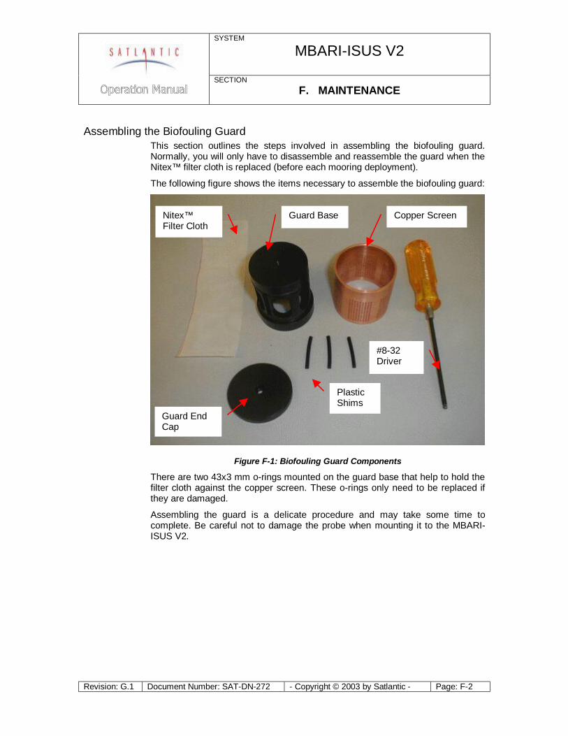
SYSTEM
MBARI-ISUS V2
SECTION F. MAINTENANCE
Revision: G.1 Document Number: SAT-DN-272 - Copyright © 2003 by Satlantic - Page: F-2
Assembling the Biofouling Guard This section outlines the steps involved in assembling the biofouling guard. Normally, you will only have to disassemble and reassemble the guard when the Nitex™ filter cloth is replaced (before each mooring deployment).
The following figure shows the items necessary to assemble the biofouling guard:
Figure F-1: Biofouling Guard Components
There are two 43x3 mm o-rings mounted on the guard base that help to hold the filter cloth against the copper screen. These o-rings only need to be replaced if they are damaged.
Assembling the guard is a delicate procedure and may take some time to complete. Be careful not to damage the probe when mounting it to the MBARI-ISUS V2.
Nitex™ Filter Cloth
Guard End Cap
Guard Base Copper Screen
Plastic Shims
#8-32 Driver
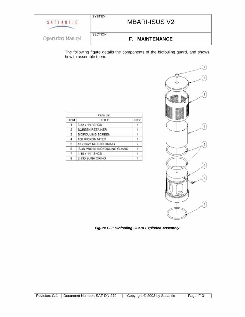
SYSTEM
MBARI-ISUS V2
SECTION F. MAINTENANCE
Revision: G.1 Document Number: SAT-DN-272 - Copyright © 2003 by Satlantic - Page: F-3
The following figure details the components of the biofouling guard, and shows how to assemble them.
Figure F-2: Biofouling Guard Exploded Assembly
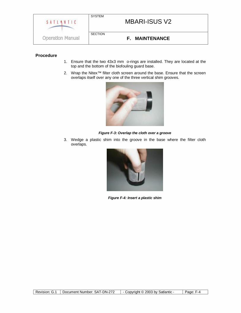
SYSTEM
MBARI-ISUS V2
SECTION F. MAINTENANCE
Revision: G.1 Document Number: SAT-DN-272 - Copyright © 2003 by Satlantic - Page: F-4
Procedure 1. Ensure that the two 43x3 mm o-rings are installed. They are located at the
top and the bottom of the biofouling guard base.
2. Wrap the Nitex™ filter cloth screen around the base. Ensure that the screen overlaps itself over any one of the three vertical shim grooves.
Figure F-3: Overlap the cloth over a groove
3. Wedge a plastic shim into the groove in the base where the filter cloth overlaps.
Figure F-4: Insert a plastic shim
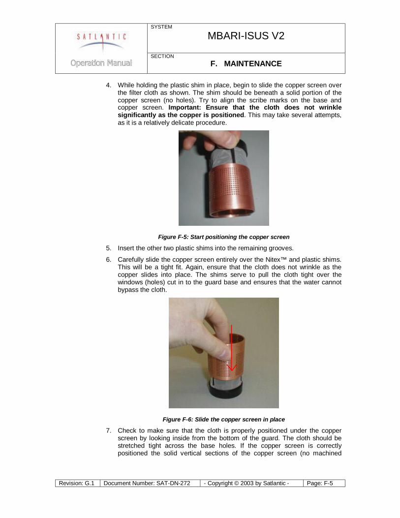
SYSTEM
MBARI-ISUS V2
SECTION F. MAINTENANCE
Revision: G.1 Document Number: SAT-DN-272 - Copyright © 2003 by Satlantic - Page: F-5
4. While holding the plastic shim in place, begin to slide the copper screen over the filter cloth as shown. The shim should be beneath a solid portion of the copper screen (no holes). Try to align the scribe marks on the base and copper screen. Important: Ensure that the cloth does not wrinkle significantly as the copper is positioned. This may take several attempts, as it is a relatively delicate procedure.
Figure F-5: Start positioning the copper screen
5. Insert the other two plastic shims into the remaining grooves.
6. Carefully slide the copper screen entirely over the Nitex™ and plastic shims. This will be a tight fit. Again, ensure that the cloth does not wrinkle as the copper slides into place. The shims serve to pull the cloth tight over the windows (holes) cut in to the guard base and ensures that the water cannot bypass the cloth.
Figure F-6: Slide the copper screen in place
7. Check to make sure that the cloth is properly positioned under the copper screen by looking inside from the bottom of the guard. The cloth should be stretched tight across the base holes. If the copper screen is correctly positioned the solid vertical sections of the copper screen (no machined
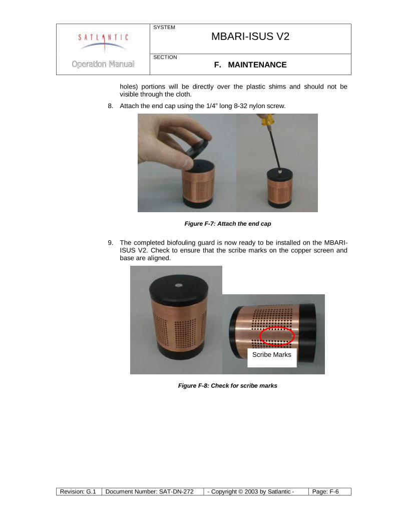
SYSTEM
MBARI-ISUS V2
SECTION F. MAINTENANCE
Revision: G.1 Document Number: SAT-DN-272 - Copyright © 2003 by Satlantic - Page: F-6
holes) portions will be directly over the plastic shims and should not be visible through the cloth.
8. Attach the end cap using the 1/4” long 8-32 nylon screw.
Figure F-7: Attach the end cap
9. The completed biofouling guard is now ready to be installed on the MBARI-
ISUS V2. Check to ensure that the scribe marks on the copper screen and base are aligned.
Figure F-8: Check for scribe marks
Scribe Marks
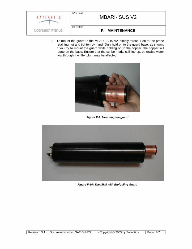
SYSTEM
MBARI-ISUS V2
SECTION F. MAINTENANCE
Revision: G.1 Document Number: SAT-DN-272 - Copyright © 2003 by Satlantic - Page: F-7
10. To mount the guard to the MBARI-ISUS V2, simply thread it on to the probe retaining nut and tighten by hand. Only hold on to the guard base, as shown. If you try to mount the guard while holding on to the copper, the copper will rotate on the base. Ensure that the scribe marks still line up, otherwise water flow through the filter cloth may be affected!
Figure F-9: Mounting the guard
Figure F-10: The ISUS with Biofouling Guard

SYSTEM
MBARI-ISUS V2
SECTION F. MAINTENANCE
Revision: G.1 Document Number: SAT-DN-272 - Copyright © 2003 by Satlantic - Page: F-8
Troubleshooting using a Terminal Emulator If you are experiencing problems receiving data with your data acquisition software, there may be a problem with the instrument, its configuration, or its physical setup. You can confirm if the instrument is transmitting telemetry using a terminal emulator.
To do this, first complete the assembly procedure described in section C START UP. Connect the instrument to a computer running a terminal emulation program. For this test, you may use either the RS-232 interface directly, or the RS-422 interface through an appropriate level converter. You can therefore use the same physical configuration you would use in the field. However, if at a later point you need to gain access to the instruments menu system, you will need to use the RS-232 interface directly.
Once the instrument is powered up and is in normal operation with free-running telemetry, you should see a regular stream of data being output to the display. However, you should be able to periodically pick out the instruments frame header or synchronization string. This series of characters appears at the beginning of every frame of telemetry, as defined in your instrument telemetry definition file. If you do not see the frame header, but you do see random characters, check that the baud rate of the terminal emulator is the same as for the instrument. If you do not see anything at all, make sure that no other application is using the serial port of the computer. If this checks out, there may be a hardware problem.
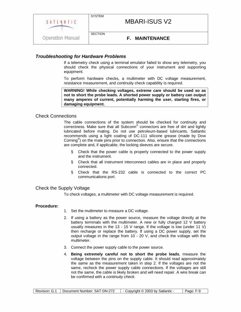
SYSTEM
MBARI-ISUS V2
SECTION F. MAINTENANCE
Revision: G.1 Document Number: SAT-DN-272 - Copyright © 2003 by Satlantic - Page: F-9
Troubleshooting for Hardware Problems If a telemetry check using a terminal emulator failed to show any telemetry, you should check the physical connections of your instrument and supporting equipment.
To perform hardware checks, a multimeter with DC voltage measurement, resistance measurement, and continuity check capability is required.
WARNING! While checking voltages, extreme care should be used so as not to short the probe leads. A shorted power supply or battery can output many amperes of current, potentially harming the user, starting fires, or damaging equipment.
Check Connections The cable connections of the system should be checked for continuity and correctness. Make sure that all Subconn® connectors are free of dirt and lightly lubricated before mating. Do not use petroleum-based lubricants. Satlantic recommends using a light coating of DC-111 silicone grease (made by Dow Corning®) on the male pins prior to connection. Also, ensure that the connections are complete and, if applicable, the locking sleeves are secure.
§ Check that the power cable is properly connected to the power supply and the instrument.
§ Check that all instrument interconnect cables are in place and properly connected.
§ Check that the RS-232 cable is connected to the correct PC communications port.
Check the Supply Voltage To check voltages, a multimeter with DC voltage measurement is required.
Procedure: 1. Set the multimeter to measure a DC voltage.
2. If using a battery as the power source, measure the voltage directly at the battery terminals with the multimeter. A new or fully charged 12 V battery usually measures in the 13 - 15 V range. If the voltage is low (under 11 V) then recharge or replace the battery. If using a DC power supply, set the output voltage in the range from 10 - 20 V, and check the voltage with the multimeter.
3. Connect the power supply cable to the power source.
4. Being extremely careful not to short the probe leads, measure the voltage between the pins on the supply cable. It should read approximately the same as the measurement taken in step 2. If the voltages are not the same, recheck the power supply cable connections. If the voltages are still not the same, the cable is likely broken and will need repair. A wire break can be confirmed with a continuity check.
SYSTEM
MBARI-ISUS V2
SECTION F. MAINTENANCE
Revision: G.1 Document Number: SAT-DN-272 - Copyright © 2003 by Satlantic - Page: F-10
5. If the voltage is within tolerance, connect the power supply cable to the ISUS.
6. Again, measure the voltage at the power supply terminals. The voltage should remain approximately the same as before, although there may be a small voltage drop when using a battery (battery voltage drops under load). If there is a significant voltage drop, disconnect the power immediately and check for shorts in the cable.
Check Cable Continuity Often, system problems can be traced to cable breaks or shorts. Usually, these cable failures are a result of improper handling or storage. Cable continuity can be checked as outlined below. Make sure all cables are completely disconnected before performing this test.
Procedure: 1. Set the multimeter to measure continuity. The resistance measurement
setting can also be used.
2. Check for continuity by measuring from pin 1 on one end of the cable to pin 1 on the other end. The meter should confirm that the connection is continuous by either giving an audible signal or measuring a low resistance. If there is not continuity, there is a break in the cable, which will require repair.
3. Repeat step 2 for all pins in the cable.
4. Check for shorts from pin 1 to all other pins by keeping one probe lead on pin 1 and touching the other probe lead to each of the other pins in the same connector in turn. Repeat this for all pins on the cable to make sure that all the pins are isolated from each other. The meter should read this as open or measure a very high resistance. If any of the pins are not isolated, there is a short in the cable, which will require repair.

SYSTEM
MBARI-ISUS V2
SECTION G. WARRANTY
Revision: G.1 Document Number: SAT-DN-272 - Copyright © 2003 by Satlantic - Page: G-1
G. WARRANTY
Warranty Period
The MBARI-ISUS V2 is under one-year parts and labor warranty from date of purchase.
Restrictions
Warranty does not apply to products that are deemed by Satlantic to be damaged by misuse, abuse, accident, or modifications by the customer. The warranty is considered void if any optical or mechanical housing is opened. In addition, the warranty is void if the warranty seal is removed, broken or otherwise damaged.
Provisions
During the one year from date of purchase warranty period, Satlantic will replace or repair, as deemed necessary, components that are defective, except as noted above, without charge to the customer.
Returns
To return products to Satlantic, whether under warranty or not, contact the Satlantic Customer Support Department and request a Returned Material Authorization (RMA) number and provide shipping details. All claims under warranty must be made promptly after occurrence of circumstances giving rise thereto and must be received by Satlantic within the applicable warranty period. Such claims should state clearly the product serial number, date of purchase (and proof thereof) and a full description of the circumstances giving rise to the claim. All replacement parts and/or products covered under the warranty period become the property of Satlantic Inc.
Liability
If your MBARI-ISUS V2 should be defective or fail to be in good working order the customer's sole remedy shall be repair or replacement as stated above. In no event will Satlantic Inc. be liable for any damages, including loss of profits, loss of savings or other incidental or consequential damages arising from the use or inability to use the MBARI-ISUS V2 or components thereof.

SYSTEM
MBARI-ISUS V2
SECTION H. CONTACT INFORMATION
Revision: G.1 Document Number: SAT-DN-272 - Copyright © 2003 by Satlantic - Page: H-1
H. CONTACT INFORMATION
If you have any problems, questions, suggestions, or comments about the instrument or manual, please contact us.
Location
Satlantic Inc. 3481 North Marginal Road Halifax, Nova Scotia B3K 5X8 Canada
PHONE: (902) 492-4780 FAX: (902) 492-4781. Email: Technical Support: [email protected]
General Inquiries: [email protected] Web: http://www.satlantic.com
Business Hours
Satlantic is normally open for business between the hours of 9:00 AM and 5:00 PM Atlantic Standard Time. The Atlantic Standard Time zone is one hour ahead of the Eastern Standard Time zone. Normally, in the winter, AST is UTC-4, but it changes to UTC–3 during the daylight saving time period in the summer. Daylight saving time is in effect from 2:00 AM on the first Sunday in April until 2:00 AM on the last Sunday in October.
Satlantic is not open for business during Canada’s statutory holidays, which are as follows:
New Year's Day January 1st
Good Friday The Friday before Easter Sunday (Easter Sunday is the first Sunday after the full moon on or following March 21st, or one week later if the full moon falls on Sunday)
Victoria Day The first Monday before May 25th
Canada Day July 1st
Halifax Natal Day The first Monday in August
Labor Day The first Monday in September
Thanksgiving Day The second Monday in October
Remembrance Day November 11th
Christmas Day December 25th
Boxing Day December 26th
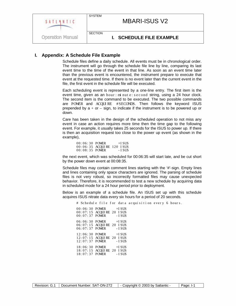
SYSTEM
MBARI-ISUS V2
SECTION I. SCHEDULE FILE EXAMPLE
Revision: G.1 Document Number: SAT-DN-272 - Copyright © 2003 by Satlantic - Page: I-1
I. Appendix: A Schedule File Example Schedule files define a daily schedule. All events must be in chronological order. The instrument will go through the schedule file line by line, comparing its last event time to the time of the event in that line. As soon as an event time later than the previous event is encountered, the instrument prepare to execute that event at the requested time. If there is no event later than the current event in the file, the first event in the schedule file will be executed.
Each scheduling event is represented by a one-line entry. The first item is the event time, given as an hour:minute:second string, using a 24 hour clock. The second item is the command to be executed. The two possible commands are POWER and ACQUIRE #SECONDS. Then follows the keyword ISUS prepended by a + or – sign, to indicate if the instrument is to be powered up or down.
Care has been taken in the design of the scheduled operation to not miss any event in case an action requires more time then the time gap to the following event. For example, it usually takes 25 seconds for the ISUS to power up. If there is then an acquisition request too close to the power up event (as shown in the example), 00:06:30 POWER +ISUS 00:06:35 ACQUIRE 120 ISUS 00:08:35 POWER -ISUS
the next event, which was scheduled for 00:06:35 will start late, and be cut short by the power down event at 00:08:35.
Schedule files may contain comment lines starting with the ‘#’-sign. Empty lines and lines containing only space characters are ignored. The parsing of schedule files is not very robust, so incorrectly formatted files may cause unexpected behavior. Therefore, it is recommended to test a new schedule by acquiring data in scheduled mode for a 24 hour period prior to deployment.
Below is an example of a schedule file. An ISUS set up with this schedule acquires ISUS nitrate data every six hours for a period of 20 seconds.
# Schedule file for data acquisition every 6 hours.
00:06:30 POWER +ISUS 00:07:15 ACQUIRE 20 ISUS 00:07:37 POWER -ISUS
06:06:30 POWER +ISUS 06:07:15 ACQUIRE 20 ISUS 06:07:37 POWER -ISUS
12:06:30 POWER +ISUS 12:07:15 ACQUIRE 20 ISUS 12:07:37 POWER -ISUS
18:06:30 POWER +ISUS 18:07:15 ACQUIRE 20 ISUS 18:07:37 POWER -ISUS
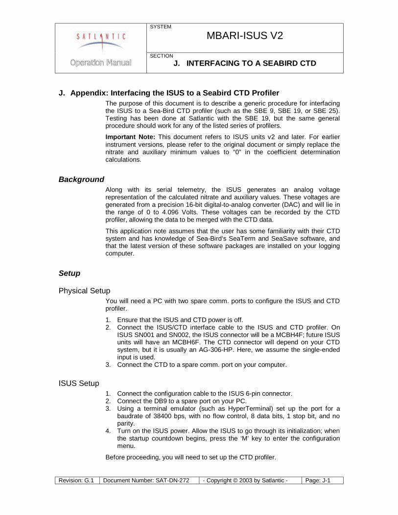
SYSTEM
MBARI-ISUS V2
SECTION J. INTERFACING TO A SEABIRD CTD
Revision: G.1 Document Number: SAT-DN-272 - Copyright © 2003 by Satlantic - Page: J-1
J. Appendix: Interfacing the ISUS to a Seabird CTD Profiler The purpose of this document is to describe a generic procedure for interfacing the ISUS to a Sea-Bird CTD profiler (such as the SBE 9, SBE 19, or SBE 25). Testing has been done at Satlantic with the SBE 19, but the same general procedure should work for any of the listed series of profilers.
Important Note: This document refers to ISUS units v2 and later. For earlier instrument versions, please refer to the original document or simply replace the nitrate and auxiliary minimum values to “0” in the coefficient determination calculations.
Background Along with its serial telemetry, the ISUS generates an analog voltage representation of the calculated nitrate and auxiliary values. These voltages are generated from a precision 16-bit digital-to-analog converter (DAC) and will lie in the range of 0 to 4.096 Volts. These voltages can be recorded by the CTD profiler, allowing the data to be merged with the CTD data.
This application note assumes that the user has some familiarity with their CTD system and has knowledge of Sea-Bird’s SeaTerm and SeaSave software, and that the latest version of these software packages are installed on your logging computer.
Setup
Physical Setup You will need a PC with two spare comm. ports to configure the ISUS and CTD profiler.
1. Ensure that the ISUS and CTD power is off. 2. Connect the ISUS/CTD interface cable to the ISUS and CTD profiler. On
ISUS SN001 and SN002, the ISUS connector will be a MCBH4F; future ISUS units will have an MCBH6F. The CTD connector will depend on your CTD system, but it is usually an AG-306-HP. Here, we assume the single-ended input is used.
3. Connect the CTD to a spare comm. port on your computer.
ISUS Setup 1. Connect the configuration cable to the ISUS 6-pin connector. 2. Connect the DB9 to a spare port on your PC. 3. Using a terminal emulator (such as HyperTerminal) set up the port for a
baudrate of 38400 bps, with no flow control, 8 data bits, 1 stop bit, and no parity.
4. Turn on the ISUS power. Allow the ISUS to go through its initialization; when the startup countdown begins, press the ‘M’ key to enter the configuration menu.
Before proceeding, you will need to set up the CTD profiler.
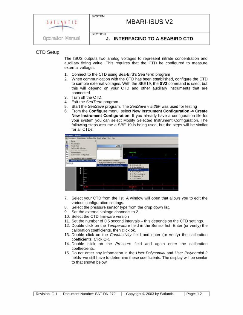
SYSTEM
MBARI-ISUS V2
SECTION J. INTERFACING TO A SEABIRD CTD
Revision: G.1 Document Number: SAT-DN-272 - Copyright © 2003 by Satlantic - Page: J-2
CTD Setup The ISUS outputs two analog voltages to represent nitrate concentration and auxiliary fitting value. This requires that the CTD be configured to measure external voltages.
1. Connect to the CTD using Sea-Bird’s SeaTerm program 2. When communication with the CTD has been established, configure the CTD
to sample external voltages. With the SBE19, the SV2 command is used, but this will depend on your CTD and other auxiliary instruments that are connected.
3. Turn off the CTD. 4. Exit the SeaTerm program. 5. Start the SeaSave program. The SeaSave v 5.26F was used for testing 6. From the Configure menu, select New Instrument Configuration -> Create
New Instrument Configuration. If you already have a configuration file for your system you can select Modify Selected Instrument Configuration. The following steps assume a SBE 19 is being used, but the steps will be similar for all CTDs.
7. Select your CTD from the list. A window will open that allows you to edit the various configuration settings.
8. Select the pressure sensor type from the drop down list. 9. Set the external voltage channels to 2. 10. Select the CTD firmware version 11. Set the number of 0.5 second intervals – this depends on the CTD settings. 12. Double click on the Temperature field in the Sensor list. Enter (or verify) the
calibration coefficients, then click ok. 13. Double click on the Conductivity field and enter (or verify) the calibration
coefficients. Click OK. 14. Double click on the Pressure field and again enter the calibration
coeffiecients. 15. Do not enter any information in the User Polynomial and User Polynomial 2
fields–we still have to determine these coefficients. The display will be similar to that shown below:
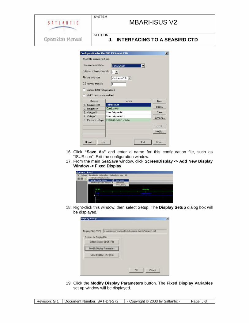
SYSTEM
MBARI-ISUS V2
SECTION J. INTERFACING TO A SEABIRD CTD
Revision: G.1 Document Number: SAT-DN-272 - Copyright © 2003 by Satlantic - Page: J-3
16. Click “Save As” and enter a name for this configuration file, such as
“ISUS.con”. Exit the configuration window. 17. From the main SeaSave window, click ScreenDisplay -> Add New Display
Window -> Fixed Display.
18. Right-click this window, then select Setup. The Display Setup dialog box will
be displayed.
19. Click the Modify Display Parameters button. The Fixed Display Variables set up window will be displayed.
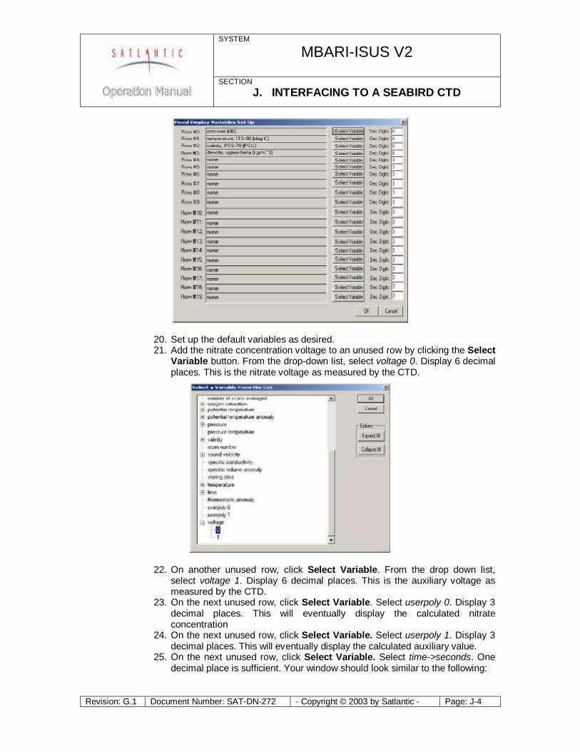
SYSTEM
MBARI-ISUS V2
SECTION J. INTERFACING TO A SEABIRD CTD
Revision: G.1 Document Number: SAT-DN-272 - Copyright © 2003 by Satlantic - Page: J-4
20. Set up the default variables as desired. 21. Add the nitrate concentration voltage to an unused row by clicking the Select
Variable button. From the drop-down list, select voltage 0. Display 6 decimal places. This is the nitrate voltage as measured by the CTD.
22. On another unused row, click Select Variable. From the drop down list, select voltage 1. Display 6 decimal places. This is the auxiliary voltage as measured by the CTD.
23. On the next unused row, click Select Variable. Select userpoly 0. Display 3 decimal places. This will eventually display the calculated nitrate concentration
24. On the next unused row, click Select Variable. Select userpoly 1. Display 3 decimal places. This will eventually display the calculated auxiliary value.
25. On the next unused row, click Select Variable. Select time->seconds. One decimal place is sufficient. Your window should look similar to the following:
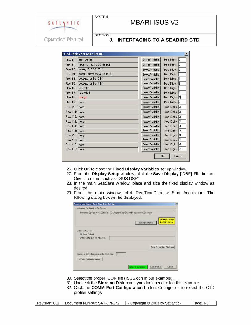
SYSTEM
MBARI-ISUS V2
SECTION J. INTERFACING TO A SEABIRD CTD
Revision: G.1 Document Number: SAT-DN-272 - Copyright © 2003 by Satlantic - Page: J-5
26. Click OK to close the Fixed Display Variables set up window. 27. From the Display Setup window, click the Save Display [.DSF] File button.
Give it a name such as “ISUS.DSF” 28. In the main SeaSave window, place and size the fixed display window as
desired. 29. From the main window, click RealTimeData -> Start Acquisition. The
following dialog box will be displayed:
30. Select the proper .CON file (ISUS.con in our example). 31. Uncheck the Store on Disk box – you don’t need to log this example 32. Click the COMM Port Configuration button. Configure it to reflect the CTD
profiler settings.
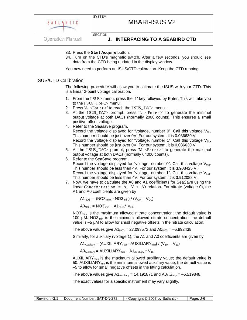
SYSTEM
MBARI-ISUS V2
SECTION J. INTERFACING TO A SEABIRD CTD
Revision: G.1 Document Number: SAT-DN-272 - Copyright © 2003 by Satlantic - Page: J-6
33. Press the Start Acquire button. 34. Turn on the CTD’s magnetic switch. After a few seconds, you should see
data from the CTD being updated in the display window.
You now need to perform an ISUS/CTD calibration. Keep the CTD running.
ISUS/CTD Calibration The following procedure will allow you to calibrate the ISUS with your CTD. This is a linear 2-point voltage calibration.
1. From the ISUS> menu, press the ‘I’ key followed by Enter. This will take you to the ISUS_INFO> menu.
2. Press ‘A <Enter>’ to reach the ISUS_DAC> menu. 3. At the ISUS_DAC> prompt, press ‘L <Enter>’ to generate the minimal
output voltage at both DACs (normally 2000 counts). This ensures a small positive offset voltage.
4. Refer to the Seasave program. Record the voltage displayed for “voltage, number 0”. Call this voltage V0L. This number should be just over 0V. For our system, it is 0.036630 V. Record the voltage displayed for “voltage, number 1”. Call this voltage V1L. This number should be just over 0V. For our system, it is 0.036630 V
5. At the ISUS_DAC> prompt, press ‘M <Enter>’ to generate the maximal output voltage at both DACs (normally 64000 counts).
6. Refer to the SeaSave program. Record the voltage displayed for “voltage, number 0”. Call this voltage V0M. This number should be less than 4V. For our system, it is 3.908425 V. Record the voltage displayed for “voltage, number 1”. Call this voltage V1M. This number should be less than 4V. For our system, it is 3.912088 V.
7. Now, we have to calculate the A0 and A1 coefficients for SeaSave using the linear Concentration = A1 V + A0 relation. For nitrate (voltage 0), the A1 and A0 coefficients are given by
A1NO3- = (NO3-max - NO3-
min) / (VOM – VOL)
A0NO3- = NO3-min − A1NO3-* VOL
NO3-max is the maximum allowed nitrate concentration; the default value is
100 µM. NO3-min is the minimum allowed nitrate concentration; the default
value is –5 µM to allow for small negative offsets in the nitrate calculation.
The above values give A1NO3 = 27.093572 and A0NO3 = –5.992438
Similarly, for auxiliary (voltage 1), the A1 and A0 coefficients are given by
A1Auxiliary = (AUXILIARYmax - AUXILIARYmin) / (V1M – V1L)
A0Auxiliary = AUXILIARYmin − A1Auxiliary * V1L
AUXILIARYmax is the maximum allowed auxiliary value; the default value is 50. AUXILIARYmin is the minimum allowed auxiliary value; the default value is –5 to allow for small negative offsets in the fitting calculation.
The above values give A1Auxiliary = 14.191871 and A0Auxiliary = –5.519848.
The exact values for a specific instrument may vary slightly.
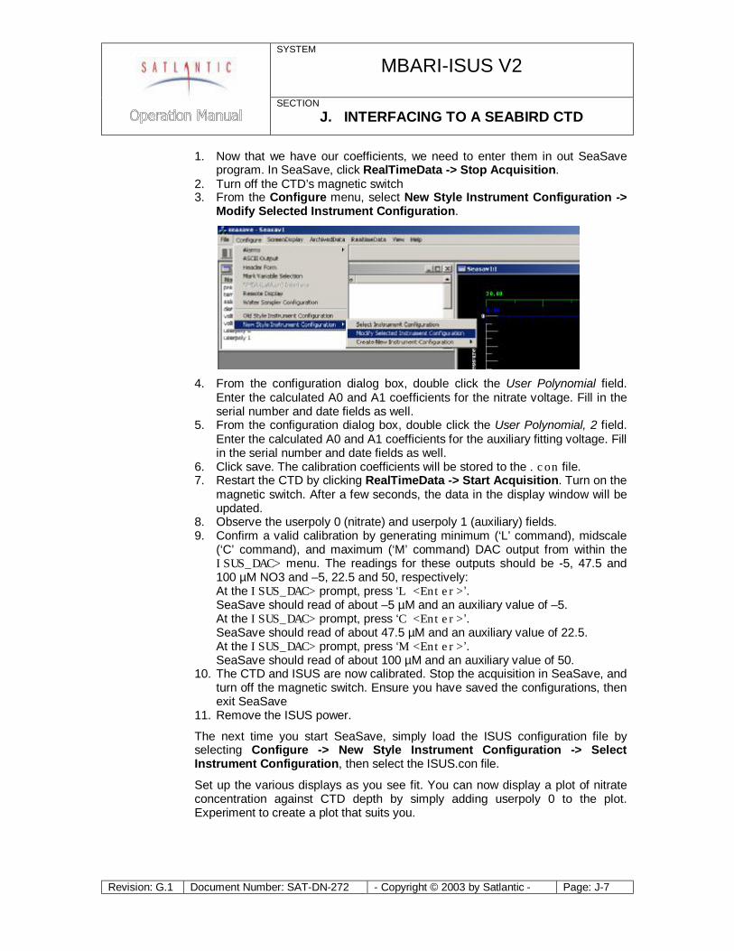
SYSTEM
MBARI-ISUS V2
SECTION J. INTERFACING TO A SEABIRD CTD
Revision: G.1 Document Number: SAT-DN-272 - Copyright © 2003 by Satlantic - Page: J-7
1. Now that we have our coefficients, we need to enter them in out SeaSave program. In SeaSave, click RealTimeData -> Stop Acquisition.
2. Turn off the CTD’s magnetic switch 3. From the Configure menu, select New Style Instrument Configuration ->
Modify Selected Instrument Configuration.
4. From the configuration dialog box, double click the User Polynomial field.
Enter the calculated A0 and A1 coefficients for the nitrate voltage. Fill in the serial number and date fields as well.
5. From the configuration dialog box, double click the User Polynomial, 2 field. Enter the calculated A0 and A1 coefficients for the auxiliary fitting voltage. Fill in the serial number and date fields as well.
6. Click save. The calibration coefficients will be stored to the .con file. 7. Restart the CTD by clicking RealTimeData -> Start Acquisition. Turn on the
magnetic switch. After a few seconds, the data in the display window will be updated.
8. Observe the userpoly 0 (nitrate) and userpoly 1 (auxiliary) fields. 9. Confirm a valid calibration by generating minimum (‘L’ command), midscale
(‘C’ command), and maximum (‘M’ command) DAC output from within the ISUS_DAC> menu. The readings for these outputs should be -5, 47.5 and 100 µM NO3 and –5, 22.5 and 50, respectively: At the ISUS_DAC> prompt, press ‘L <Enter>’. SeaSave should read of about –5 µM and an auxiliary value of –5. At the ISUS_DAC> prompt, press ‘C <Enter>’. SeaSave should read of about 47.5 µM and an auxiliary value of 22.5. At the ISUS_DAC> prompt, press ‘M <Enter>’. SeaSave should read of about 100 µM and an auxiliary value of 50.
10. The CTD and ISUS are now calibrated. Stop the acquisition in SeaSave, and turn off the magnetic switch. Ensure you have saved the configurations, then exit SeaSave
11. Remove the ISUS power.
The next time you start SeaSave, simply load the ISUS configuration file by selecting Configure -> New Style Instrument Configuration -> Select Instrument Configuration, then select the ISUS.con file.
Set up the various displays as you see fit. You can now display a plot of nitrate concentration against CTD depth by simply adding userpoly 0 to the plot. Experiment to create a plot that suits you.
SYSTEM
MBARI-ISUS V2
SECTION K. USB VIRTUAL COM PORT DRIVERS
Revision: G.1 Document Number: SAT-DN-272 - Copyright © 2003 by Satlantic - Page: K-1
K. Appendix: Installing USB Virtual COM Port Drivers To communicate with the ISUS using the USB port, VCP (Virtual COM Port) drivers must be installed on the computer that will be connected to the ISUS. These drivers allow a USB port to emulate a standard serial port so that terminal emulators such as Windows HyperTerminal may be used. The drivers are included on the compact disc provided with your ISUS system. Drivers are included for Microsoft Windows XP, Windows 2000, and Windows 98, and must be installed before connecting the ISUS to the computer’s USB port.
The CD accompanying the instrument contains a folder “USB required files” containing two .zip files. The first file, P8002104.zip, is WHQL Certified for Windows XP, released on 7-22-2002. However, a more recent release dated 10-03-2004 is available in the r9052154.zip file, and is the version used by Satlantic during testing on a PC running Windows XP SP2. You may wish to check with the USB component manufacturers for more recent releases at http://www.dlpdesign.com or http://www.ftdichip.com. If you encounter problems during installation, or for a more detailed installation procedure, refer to the appropriate installation guide provided in the file folder. The appropriate device is the FT245BM.
To install the VCP drivers on your PC, use the following procedure:
1. Unzip the desired file onto your hard drive. Choose an easy-to-find location (e.g. C:\Program Files\Satlantic\USBDrivers) to make future updates easy.
2. Connect the ISUS to a spare USB port on your PC. Note that the ISUS USB hardware is powered from the PC’s USB port, so a separate power source for the ISUS is not required.
3. The Windows Found New Hardware wizard should start automatically. When it asks to connect to Windows Update to search for software, select “No, not this time”. Click next to continue.
4. Select “Install from a list or specific location” and click next to continue.
5. Instruct Windows to “Search for the best driver in these locations”; uncheck the “Search removable media box” and select “Include this location in the search”; browse to the folder where you’ve unzipped the drivers and click next to continue.
6. If you are using the non-WHQL certified drivers, you should see a warning message; click on “Continue Anyway” to proceed. Windows will then copy the required driver files; you should see “USB Serial Converter” in the installation window.
7. Click finish when the installation is completed. Keep the USB port connected to the ISUS.
8. The COM port emulation driver must be installed next, and should be initiated automatically by the PC with the Windows Found New Hardware Wizard; repeat steps 3 to 7.
9. When the installation is complete, open the Device Manager (located in “Control Panel\System”, then select the “Hardware” tab and then click the “Device Manager” button).
SYSTEM
MBARI-ISUS V2
SECTION K. USB VIRTUAL COM PORT DRIVERS
Revision: G.1 Document Number: SAT-DN-272 - Copyright © 2003 by Satlantic - Page: K-2
10. Select “View->Devices by Type”. The ISUS should appear as an additional COM port with the label “USB Serial Port” and an indication of the COM port number it is associated with (e.g. COM5). Depending on the terminal emulator you intend to use, you may have to change the COM port number association to a value that can be accessed by the program. For example, some emulators can only access 4 COM ports, so the COM5 above would have to be changed to a lower, unused value. To change the association, double-click on the USB Serial Port in the Device Manager, select the “Port Settings” tab, and click the “Advanced” button. A drop down list allows the port number to be selected.
The USB VCP Drivers should now be successfully installed, and you may remove the USB connection.
SYSTEM
MBARI-ISUS V2
SECTION L. USING HYPERTERM
Revision: G.1 Document Number: SAT-DN-272 - Copyright © 2003 by Satlantic - Page: L-1
L. Appendix: Using Windows HyperTerminaL Most Satlantic instruments use serial communications for interfacing with the outside world. This type of interface is simple to operate and convenient for applications such as these. Although the instrument’s telemetry interface is used mainly for broadcasting telemetry, it can also be used to establish a human user interface to configure and test the instrument. A Terminal emulation program is needed to use this interface, or to directly monitor instrument telemetry. These programs have many common uses such as communicating with bulletin board services, remotely logging on to other computers on a network, or communicating directly with your modem. You can also use it for direct communications with a serial port, which is ideal for communicating with Satlantic instruments.
There are many types of terminal emulation programs. Most of these are suitable for this application, so you are free to use whatever terminal emulator you are comfortable with. If you are unfamiliar with terminal emulators, this tutorial will help you get started with the emulator program that is distributed with Windows
called HyperTerminal.
Installation of HyperTerm The first step in using HyperTerminal is to make sure it is installed. One way of starting the application is to use the Start button on your desktop. Select “Run…” and type “hypertrm” in the space provided. If the program cannot be found, it has probably not been installed. You can also check for a HyperTerminal installation by selecting Start -> Programs -> Accessories. If a HyperTerminal folder is visible in the Accessories folder, HyperTerminal is already installed.
If HyperTerminal is not installed, it is an easy matter to install it now. In Windows 95/98, open the Control Panel by selecting Start -> Control Panel. Open the Add/Remove Programs control. When you have setup these dialog boxes as shown below, press the OK button in each one. Windows will now install HyperTerminal on your computer. You may need your Windows Setup Disks/CD for this to complete. Just follow the on-screen instructions.
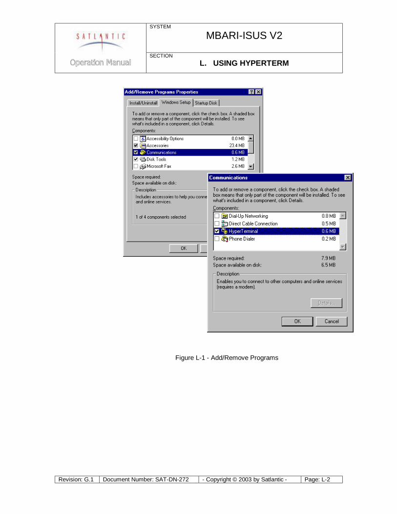
SYSTEM
MBARI-ISUS V2
SECTION L. USING HYPERTERM
Revision: G.1 Document Number: SAT-DN-272 - Copyright © 2003 by Satlantic - Page: L-2
Figure L-1 - Add/Remove Programs
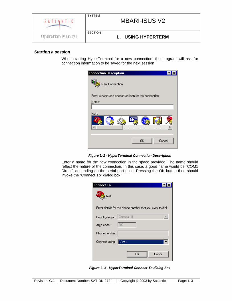
SYSTEM
MBARI-ISUS V2
SECTION L. USING HYPERTERM
Revision: G.1 Document Number: SAT-DN-272 - Copyright © 2003 by Satlantic - Page: L-3
Starting a session When starting HyperTerminal for a new connection, the program will ask for connection information to be saved for the next session.
Figure L-2 - HyperTerminal Connection Description
Enter a name for the new connection in the space provided. The name should reflect the nature of the connection. In this case, a good name would be “COM1 Direct”, depending on the serial port used. Pressing the OK button then should invoke the “Connect To” dialog box:
Figure L-3 - HyperTerminal Connect To dialog box
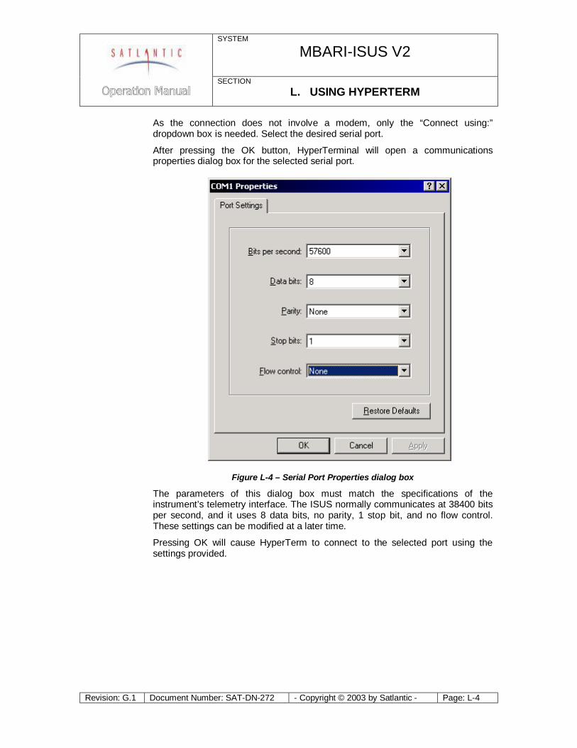
SYSTEM
MBARI-ISUS V2
SECTION L. USING HYPERTERM
Revision: G.1 Document Number: SAT-DN-272 - Copyright © 2003 by Satlantic - Page: L-4
As the connection does not involve a modem, only the “Connect using:” dropdown box is needed. Select the desired serial port.
After pressing the OK button, HyperTerminal will open a communications properties dialog box for the selected serial port.
Figure L-4 – Serial Port Properties dialog box
The parameters of this dialog box must match the specifications of the instrument’s telemetry interface. The ISUS normally communicates at 38400 bits per second, and it uses 8 data bits, no parity, 1 stop bit, and no flow control. These settings can be modified at a later time.
Pressing OK will cause HyperTerm to connect to the selected port using the settings provided.
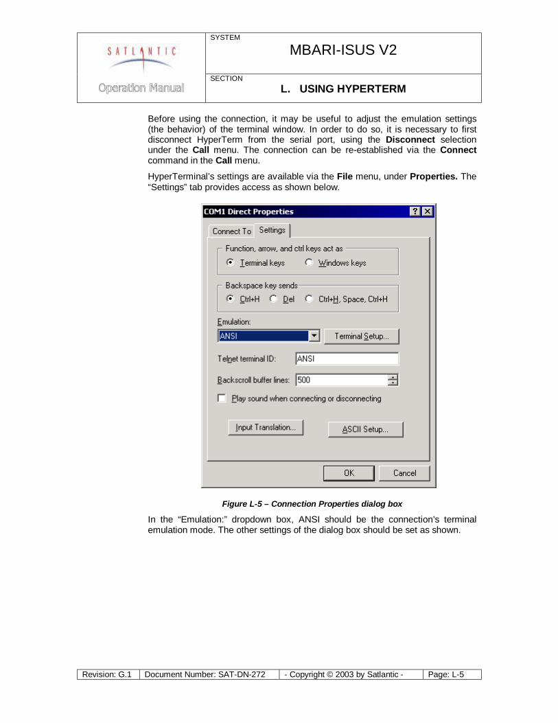
SYSTEM
MBARI-ISUS V2
SECTION L. USING HYPERTERM
Revision: G.1 Document Number: SAT-DN-272 - Copyright © 2003 by Satlantic - Page: L-5
Before using the connection, it may be useful to adjust the emulation settings (the behavior) of the terminal window. In order to do so, it is necessary to first disconnect HyperTerm from the serial port, using the Disconnect selection under the Call menu. The connection can be re-established via the Connect command in the Call menu.
HyperTerminal’s settings are available via the File menu, under Properties. The “Settings” tab provides access as shown below.
Figure L-5 – Connection Properties dialog box
In the “Emulation:” dropdown box, ANSI should be the connection’s terminal emulation mode. The other settings of the dialog box should be set as shown.
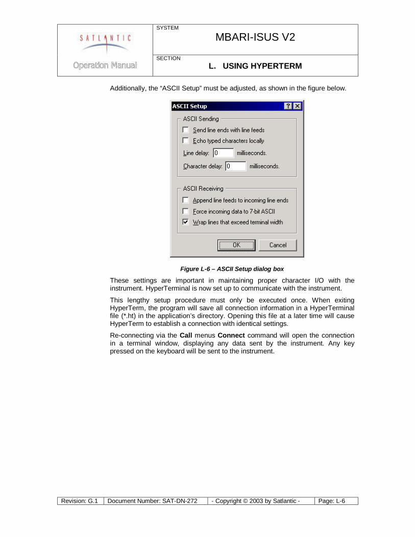
SYSTEM
MBARI-ISUS V2
SECTION L. USING HYPERTERM
Revision: G.1 Document Number: SAT-DN-272 - Copyright © 2003 by Satlantic - Page: L-6
Additionally, the “ASCII Setup” must be adjusted, as shown in the figure below.
Figure L-6 – ASCII Setup dialog box
These settings are important in maintaining proper character I/O with the instrument. HyperTerminal is now set up to communicate with the instrument.
This lengthy setup procedure must only be executed once. When exiting HyperTerm, the program will save all connection information in a HyperTerminal file (*.ht) in the application’s directory. Opening this file at a later time will cause HyperTerm to establish a connection with identical settings.
Re-connecting via the Call menus Connect command will open the connection in a terminal window, displaying any data sent by the instrument. Any key pressed on the keyboard will be sent to the instrument.
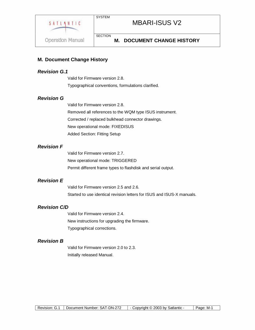
SYSTEM
MBARI-ISUS V2
SECTION M. DOCUMENT CHANGE HISTORY
Revision: G.1 Document Number: SAT-DN-272 - Copyright © 2003 by Satlantic - Page: M-1
M. Document Change History
Revision G.1 Valid for Firmware version 2.8.
Typographical conventions, formulations clarified.
Revision G Valid for Firmware version 2.8.
Removed all references to the WQM type ISUS instrument.
Corrected / replaced bulkhead connector drawings.
New operational mode: FIXEDISUS
Added Section: Fitting Setup
Revision F Valid for Firmware version 2.7.
New operational mode: TRIGGERED
Permit different frame types to flashdisk and serial output.
Revision E Valid for Firmware version 2.5 and 2.6.
Started to use identical revision letters for ISUS and ISUS-X manuals.
Revision C/D Valid for Firmware version 2.4.
New instructions for upgrading the firmware.
Typographical corrections.
Revision B Valid for Firmware version 2.0 to 2.3.
Initially released Manual.