maxq development tools guide
TRANSCRIPT

Version 1.0 1 of 23 March 9, 2007
OVERVIEW Two development tools, MAX-IDE and the Microcontroller Tool Kit (MTK), are provided by Dallas/Maxim to assist in creating and debugging applications for the MAXQTM family of microcontrollers. Both tools are compatible with all MAXQ microcontrollers and evaluation kits and may be downloaded freely from the Dallas Semiconductor FTP site at http://files.dalsemi.com. MAX-IDE The MAX-IDE development environment is used to write, debug and test assembly-based applications for MAXQ microcontrollers. It is designed to work with standard MAXQ evaluation kits or user-designed systems, and provides the following features. • Project-based development environment for MAXQ assembly applications • Multiple-window code editor including automatic syntax highlighting for MAXQ assembly • Integrated MAXQ assembler for MAXQ10, MAXQ20 and MAXQ30 cores • Integrated macro preprocessor providing C-style defines, equates, conditional assembly and macros • In-circuit application loading using the JTAG interface and ROM bootloader (for MAXQ microcontrollers with
flash or EEPROM program memory) • In-application debugging features available over the JTAG interface include breakpointing, step-by-step
program execution, viewing and editing of memory and register contents • Integrated help system Microcontroller Tool Kit (MTK) The Microcontroller Tool Kit, also known as MTK, encapsulates a wide range of bootloader, configuration and programming utilities for MAXQ and 8051-compatible microcontrollers developed by Dallas/Maxim. This guide covers the MAXQ-specific features of MTK, which include the following. • JTAG bootloader interface (using the Serial-to-JTAG interface board) • Access to standard MAXQ bootloader functions including
o Device identification (ROM banner) o Password protection functions o Master erase o Reading, writing, CRC verification and direct verification of program memory contents o Reading, writing, CRC verification and direct verification of data memory contents o Device specific functions (code protection lock, read/write configuration registers, etc.) which vary from
one MAXQ device to the next • Standard “dumb terminal” mode which can be used to interface with user application software or communicate
directly with the Serial-to-JTAG interface
MaxQ Development Tools Guide
www.maxim-ic.com

MAXQ Development Tools Guide
Version 1.0 2 of 23 March 9, 2007
References This guide covers the use of the MAX-IDE and MTK development tools. Additionally, the following references should be used when developing applications for any MAXQ microcontroller. • The MAXQ Family User’s Guide (http://www.maxim-ic.com/MAXQUG) contains detailed information on the
common features shared by MAXQ microcontrollers, including the MAXQ instruction set itself. It also includes information on the system registers (which are used to control core functions) as well as information on peripherals commonly found on MAXQ microcontrollers, which include timers, port pins, serial USART and SPI interfaces, hardware multipliers, and others.
• The functionality specific to a particular MAXQ microcontroller is detailed by two documents which are available from the QuickView page for that device – the datasheet and the User’s Guide supplement. The datasheet provides an overview of functionality and describes the device’s pinout, packaging, electrical characteristics and timing requirements. The User’s Guide supplement describes the device from a programming standpoint including memory architecture, additional peripherals and peripheral registers, while also listing any differences between the device’s functionality and the generic functionality described in the MAXQ Family User’s Guide.
• The latest version of this guide is available online at: http://files.dalsemi.com/microcontroller/maxq/information/MaxQDevTools.pdf
• The MaxQ Core Assembly Guide, which discusses features and usage of the MaxQ assembler (maxqasm) and the Macro preprocessor, is available online at: http://files.dalsemi.com/microcontroller/maxq/information/MaxQCoreAsm.pdf
• For general questions about MAXQ microcontrollers or development tools, see the Dallas/Maxim discussion board at http://discuss.dalsemi.com/.
• Finally, online help for MAX-IDE and MTK is available from each application’s Help menu under Help →→→→ Contents.
MAXQ Development Tools Guide
Version 1.0 3 of 23 March 9, 2007
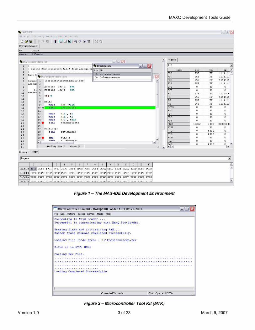
Figure 1 – The MAX-IDE Development Environment
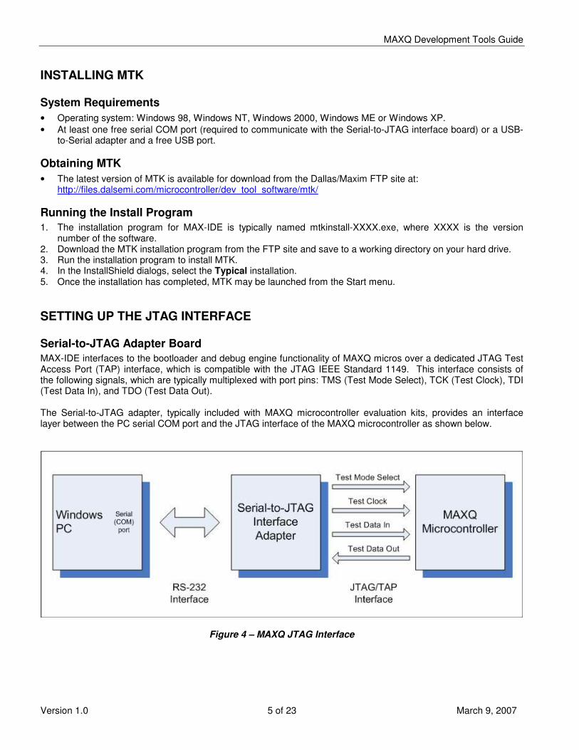
Figure 2 – Microcontroller Tool Kit (MTK)

MAXQ Development Tools Guide
Version 1.0 4 of 23 March 9, 2007
INSTALLING MAX-IDE System Requirements • Operating system: Windows 98, Windows NT, Windows 2000, Windows ME or Windows XP. • At least one free serial COM port, or a USB-to-Serial adapter and a free USB port. Obtaining MAX-IDE • Installation files for MAX-IDE are included on the software CDs packaged with all MAXQ evaluation kits. • The latest version of MAX-IDE is also available for download from the Dallas/Maxim FTP site at:
http://files.dalsemi.com/microcontroller/maxq/dev_tool_software/MAX-IDE/MAX-IDE.zip Running the Install Program 1. If installing MAX-IDE from an evaluation kit CD, there may be a single self-extracting installation executable
(MAX-IDE.exe), or a Setup.exe file in an installation directory. Run this program to install MAX-IDE. 2. If installing MAX-IDE from the FTP site ZIP file, unpack the MAX-IDE.zip file to a working directory, and then
run the Setup.exe file. 3. In the InstallShield dialogs, select the Typical installation (Figure 3). 4. Once the installation has completed, MAX-IDE may be launched from the Start menu. MAX-IDE Installed Files The main executable and help files for MAX-IDE are located in the MAX-IDE root directory, placed by default at {Program Files}\MAX-IDE. Additional files are located in the following subdirectories. • The Compilers subdirectory contains executables and data files for all compilers and assemblers installed with
MAX-IDE. At a minimum, this will include the standard MAXQ assembler and Macro preprocessor; other assemblers and compilers may also be installed depending on the distribution you are using.
• The Devices subdirectory contains libraries, drivers and configuration files to target applications for and communicate with MAXQ microcontrollers and evaluation kits.
• In versions of MAX-IDE installed from evaluation kit CDs, the Examples subdirectory may contain code samples (in <device directory>/xxx_Demo) and standard include files and libraries (in <device directory>/api) for one or more MAXQ microcontrollers.
Figure 3 – MAX-IDE Installation
MAXQ Development Tools Guide
Version 1.0 5 of 23 March 9, 2007
INSTALLING MTK System Requirements • Operating system: Windows 98, Windows NT, Windows 2000, Windows ME or Windows XP. • At least one free serial COM port (required to communicate with the Serial-to-JTAG interface board) or a USB-
to-Serial adapter and a free USB port. Obtaining MTK • The latest version of MTK is available for download from the Dallas/Maxim FTP site at:
http://files.dalsemi.com/microcontroller/dev_tool_software/mtk/ Running the Install Program 1. The installation program for MAX-IDE is typically named mtkinstall-XXXX.exe, where XXXX is the version
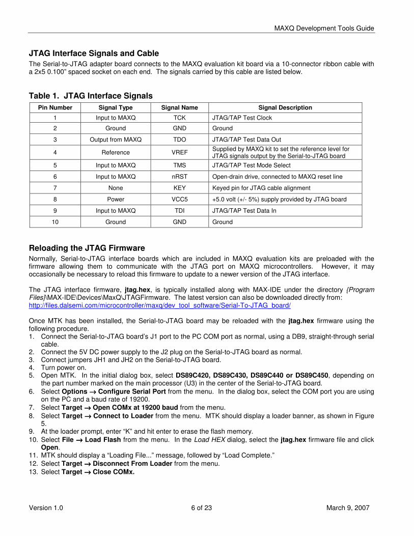
number of the software. 2. Download the MTK installation program from the FTP site and save to a working directory on your hard drive. 3. Run the installation program to install MTK. 4. In the InstallShield dialogs, select the Typical installation. 5. Once the installation has completed, MTK may be launched from the Start menu. SETTING UP THE JTAG INTERFACE Serial-to-JTAG Adapter Board MAX-IDE interfaces to the bootloader and debug engine functionality of MAXQ micros over a dedicated JTAG Test Access Port (TAP) interface, which is compatible with the JTAG IEEE Standard 1149. This interface consists of the following signals, which are typically multiplexed with port pins: TMS (Test Mode Select), TCK (Test Clock), TDI (Test Data In), and TDO (Test Data Out). The Serial-to-JTAG adapter, typically included with MAXQ microcontroller evaluation kits, provides an interface layer between the PC serial COM port and the JTAG interface of the MAXQ microcontroller as shown below.
Figure 4 – MAXQ JTAG Interface
MAXQ Development Tools Guide
Version 1.0 6 of 23 March 9, 2007
JTAG Interface Signals and Cable The Serial-to-JTAG adapter board connects to the MAXQ evaluation kit board via a 10-connector ribbon cable with a 2x5 0.100” spaced socket on each end. The signals carried by this cable are listed below. Table 1. JTAG Interface Signals
Pin Number Signal Type Signal Name Signal Description
1 Input to MAXQ TCK JTAG/TAP Test Clock
2 Ground GND Ground
3 Output from MAXQ TDO JTAG/TAP Test Data Out
4 Reference VREF Supplied by MAXQ kit to set the reference level for JTAG signals output by the Serial-to-JTAG board
5 Input to MAXQ TMS JTAG/TAP Test Mode Select
6 Input to MAXQ nRST Open-drain drive, connected to MAXQ reset line
7 None KEY Keyed pin for JTAG cable alignment
8 Power VCC5 +5.0 volt (+/- 5%) supply provided by JTAG board
9 Input to MAXQ TDI JTAG/TAP Test Data In
10 Ground GND Ground
Reloading the JTAG Firmware Normally, Serial-to-JTAG interface boards which are included in MAXQ evaluation kits are preloaded with the firmware allowing them to communicate with the JTAG port on MAXQ microcontrollers. However, it may occasionally be necessary to reload this firmware to update to a newer version of the JTAG interface. The JTAG interface firmware, jtag.hex, is typically installed along with MAX-IDE under the directory {Program Files}\MAX-IDE\Devices\MaxQ\JTAGFirmware. The latest version can also be downloaded directly from: http://files.dalsemi.com/microcontroller/maxq/dev_tool_software/Serial-To-JTAG_board/ Once MTK has been installed, the Serial-to-JTAG board may be reloaded with the jtag.hex firmware using the following procedure. 1. Connect the Serial-to-JTAG board’s J1 port to the PC COM port as normal, using a DB9, straight-through serial
cable. 2. Connect the 5V DC power supply to the J2 plug on the Serial-to-JTAG board as normal. 3. Connect jumpers JH1 and JH2 on the Serial-to-JTAG board. 4. Turn power on. 5. Open MTK. In the initial dialog box, select DS89C420, DS89C430, DS89C440 or DS89C450, depending on
the part number marked on the main processor (U3) in the center of the Serial-to-JTAG board. 6. Select Options →→→→ Configure Serial Port from the menu. In the dialog box, select the COM port you are using
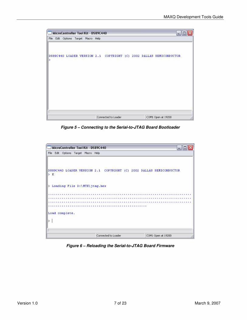
on the PC and a baud rate of 19200. 7. Select Target →→→→ Open COMx at 19200 baud from the menu. 8. Select Target →→→→ Connect to Loader from the menu. MTK should display a loader banner, as shown in Figure
5. 9. At the loader prompt, enter “K” and hit enter to erase the flash memory. 10. Select File →→→→ Load Flash from the menu. In the Load HEX dialog, select the jtag.hex firmware file and click
Open. 11. MTK should display a “Loading File...” message, followed by “Load Complete.” 12. Select Target →→→→ Disconnect From Loader from the menu. 13. Select Target →→→→ Close COMx.
MAXQ Development Tools Guide
Version 1.0 7 of 23 March 9, 2007
Figure 5 – Connecting to the Serial-to-JTAG Board Bootloader
Figure 6 – Reloading the Serial-to-JTAG Board Firmware
MAXQ Development Tools Guide
Version 1.0 8 of 23 March 9, 2007
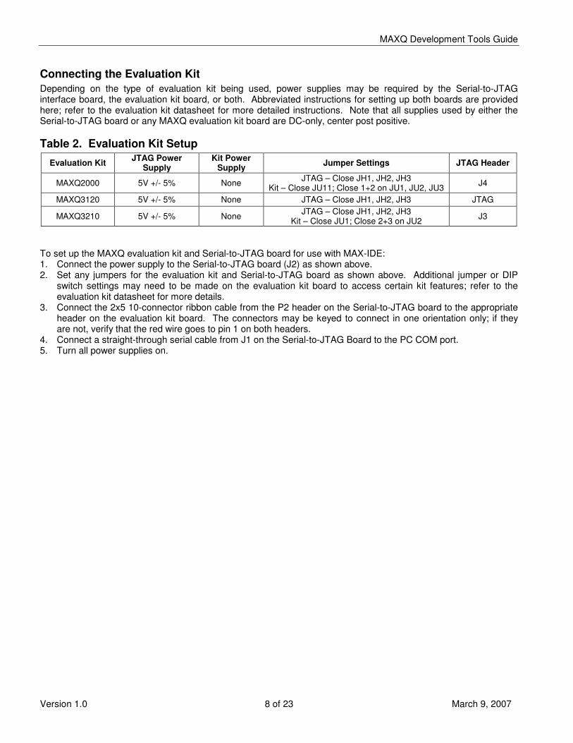
Connecting the Evaluation Kit Depending on the type of evaluation kit being used, power supplies may be required by the Serial-to-JTAG interface board, the evaluation kit board, or both. Abbreviated instructions for setting up both boards are provided here; refer to the evaluation kit datasheet for more detailed instructions. Note that all supplies used by either the Serial-to-JTAG board or any MAXQ evaluation kit board are DC-only, center post positive. Table 2. Evaluation Kit Setup
Evaluation Kit JTAG Power Supply
Kit Power Supply Jumper Settings JTAG Header
MAXQ2000 5V +/- 5% None JTAG – Close JH1, JH2, JH3 Kit – Close JU11; Close 1+2 on JU1, JU2, JU3 J4
MAXQ3120 5V +/- 5% None JTAG – Close JH1, JH2, JH3 JTAG
MAXQ3210 5V +/- 5% None JTAG – Close JH1, JH2, JH3 Kit – Close JU1; Close 2+3 on JU2 J3
To set up the MAXQ evaluation kit and Serial-to-JTAG board for use with MAX-IDE: 1. Connect the power supply to the Serial-to-JTAG board (J2) as shown above. 2. Set any jumpers for the evaluation kit and Serial-to-JTAG board as shown above. Additional jumper or DIP
switch settings may need to be made on the evaluation kit board to access certain kit features; refer to the evaluation kit datasheet for more details.
3. Connect the 2x5 10-connector ribbon cable from the P2 header on the Serial-to-JTAG board to the appropriate header on the evaluation kit board. The connectors may be keyed to connect in one orientation only; if they are not, verify that the red wire goes to pin 1 on both headers.
4. Connect a straight-through serial cable from J1 on the Serial-to-JTAG Board to the PC COM port. 5. Turn all power supplies on.

MAXQ Development Tools Guide
Version 1.0 9 of 23 March 9, 2007
WORKING WITH PROJECTS IN MAX-IDE Creating a New MAXQ Assembly Project To create a new MAXQ assembly language project in MAX-IDE, follow these steps. 1. From the MAX-IDE menu, select Device →→→→ MAXQ JTAG. 2. Select Project →→→→ New Project. An untitled project will be created. 3. Select Project →→→→ Save Project As. Select the location you want to save your project (.prj file) to. 4. To create a new assembly language file, select File →→→→ New File. After you have entered the assembly code
into the file, select File →→→→ Save As, and save the newly created .asm file in your project directory. Next, select Project →→→→ Add Files, and select the newly created file to add to your project.
5. To add an existing assembly language file to your project, simply select Project →→→→ Add Files, and select the file to be added to the project.
6. Include files do not need to be formally added to the project, since they are read automatically during the assembly process.
An example assembly file for the MAXQ2000 would be: $include (..\api\maxQ2000.inc) org 0000h main: jump $ end The $include line above will vary depending on the location of the include file. For more details on the $include and org directives, refer to the MAXQ Core Assembly Guide. Notes on assembly and include files • The system registers common to all MAXQ microcontrollers (such as the accumulators, data pointers and loop
control registers) are predefined in the MAX-IDE assembler. The peripheral registers, which are different for each device, must be defined in an include file. Standard include files are included with the MAX-IDE install for each MAXQ microcontroller; the include file shown in the above example is for the MAXQ2000.
• Preprocessor directives (such as equates, defines and macros) do not carry over from file to file within a project. If a MAX-IDE assembly project contains more than one assembly file, any preprocessor directives or include file directives must be contained in each assembly file that uses them.
• Regardless of the number of assembly files in a project, an “end” statement must appear at the end of each file.
• Do not put “end” statements at the end of include files. • When multiple assembly files are included in a project, all identifiers in all files are effectively public; that is,
code in any assembly file may call routines or refer to labels defined in any other assembly file in that project.

MAXQ Development Tools Guide
Version 1.0 10 of 23 March 9, 2007
Opening an Existing Project To open a previously created MAX-IDE project, simply select Project →→→→ Open Project from the menu and select the .prj file of the project you wish to open. Note that opening a MAXQ JTAG project when the Serial-to-JTAG board and evaluation kit board are not connected correctly and powered up may result in an error message. Once a project has been created or opened, assembly code files included in the project will be listed in the panel on the left. Double-clicking on a file name will open it for editing in MAX-IDE. RUNNING AND DEBUGGING CODE IN MAX-IDE Compiling a Project To compile project files, select Debug →→→→ Make or Debug →→→→ Build All from the menu, click one of the shortcut buttons for these commands on the toolbar, or hit F7 (same as Make). The MAXQ assembler will run, and if there are no errors, the message “Compiling...Build Successful.” will be displayed in the Messages window. Any errors from the build will also be displayed in the Messages window. Running a Project Once a project has been successfully compiled, it can be executed in the debugger using one of several methods. • Selecting Debug →→→→ Run (F5) will load the compiled project code into the MAXQ microcontroller over the JTAG
interface and start execution. Program execution will continue until Debug →→→→ Stop (Shift+F5) is selected, the Pause button is clicked or a breakpoint is encountered.
• Selecting Debug →→→→ Step Into (F11) will load the compiled program and halt execution at the first source code line.
• Selecting Debug →→→→ Run to Cursor (Control+F10) will load the compiled program, start execution and run until the execution point reaches the line that the editing cursor occupies or until it reaches a breakpoint, whichever occurs first. If the cursor is not on a source code line, selecting this option will result in an error.
Breakpoints, which halt program execution at a predetermined location, can be set or cleared by one of three methods. • Move the cursor to the line you wish to breakpoint and select Debug →→→→ Toggle Breakpoint. • Move the cursor to the line you wish to breakpoint and click the stoplight icon in the toolbar. • Click the line number of the line you wish to breakpoint in the editing window. Note that a breakpoint can be placed on a non-source code line, but this will have no effect. MAXQ microcontrollers allow up to four breakpoints to be set at once; if Run to Cursor is selected, this uses up a breakpoint, so only three may be set in this case. Selecting Debug →→→→ Stop or clicking the Stop icon in the toolbar shuts down program execution completely. However, when execution stops at the first line (Step Into), at the cursor line (Run to Cursor), or at a line with a breakpoint set, the program may then be executed in step-by-step mode. Step-by-step mode may also be entered by clicking the Pause button. In this mode, the current execution point is marked with a green arrow, and the following commands may be used. • Debug →→→→ Step Into (F11), Debug →→→→ Step Over (F10), and Debug →→→→ Step Out (Shift+F10) all have the same
effect in assembly debug mode, which is to execute a single instruction and move the execution point to the next instruction.
• Debug →→→→ Run will run from the current execution point until the next breakpoint is reached, as described above.
• Debug →→→→ Run To Cursor will run from the current execution point until the cursor line is reached, as described above.
Note - the High-Level Debug and Low-Level Debug settings in the Debug menu have no effect when running in assembly language debugging mode.
MAXQ Development Tools Guide
Version 1.0 11 of 23 March 9, 2007
Notes on Running Projects and Master Erase Every time the project code is executed using the Run command, MAX-IDE connects to the MAXQ microcontroller through the Serial-to-JTAG board and sends the following sequence of commands. 1. Master Erase – clears all program and data memory in the MAXQ microcontroller. Note that for
microcontrollers with nonvolatile data memory, such as the MAXQ3210 and MAXQ3212, this will typically clear the nonvolatile data memory as well each time the project is run.
2. Load Code – Loads all project code (filename.hex) into program space on the MAXQ microcontroller. 3. Load Data – If the project contains any “segment data” statements, any data assembled into the data segment
(filename_d.hex) will be loaded into the data space on the MAXQ microcontroller, if the MAXQ microcontroller’s bootloader supports this. Note that if the MAXQ microcontroller’s data space is volatile (RAM), the bootloader may still allow the data to be loaded there by MAX-IDE, but it will only remain loaded until the next power cycle.
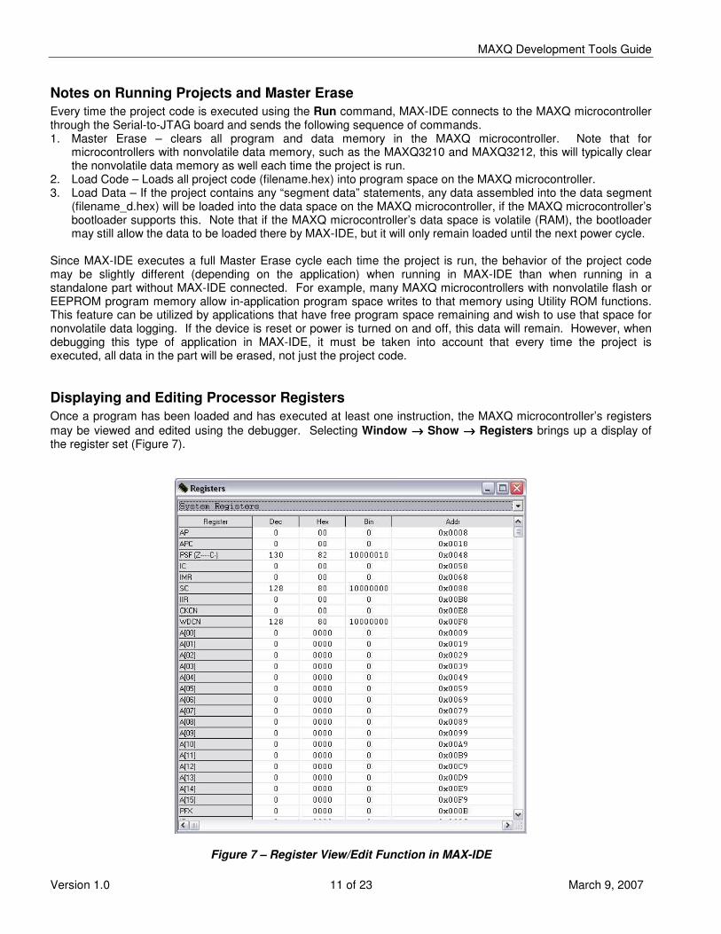
Since MAX-IDE executes a full Master Erase cycle each time the project is run, the behavior of the project code may be slightly different (depending on the application) when running in MAX-IDE than when running in a standalone part without MAX-IDE connected. For example, many MAXQ microcontrollers with nonvolatile flash or EEPROM program memory allow in-application program space writes to that memory using Utility ROM functions. This feature can be utilized by applications that have free program space remaining and wish to use that space for nonvolatile data logging. If the device is reset or power is turned on and off, this data will remain. However, when debugging this type of application in MAX-IDE, it must be taken into account that every time the project is executed, all data in the part will be erased, not just the project code. Displaying and Editing Processor Registers Once a program has been loaded and has executed at least one instruction, the MAXQ microcontroller’s registers may be viewed and edited using the debugger. Selecting Window →→→→ Show →→→→ Registers brings up a display of the register set (Figure 7).
Figure 7 – Register View/Edit Function in MAX-IDE

MAXQ Development Tools Guide
Version 1.0 12 of 23 March 9, 2007
These values will update as you step through code in the debugger. Writeable registers may be edited by double-clicking in their value fields and entering new values in hex, decimal or binary. Right-clicking anywhere in the Registers window brings up a popup menu which can be used to configure which columns are displayed. • Decimal – Displays register contents in decimal format. A new value for the register (for writeable bits) may be
entered by double-clicking in this column and entering a new value in decimal. • Hexadecimal – Displays register contents in hex format. A new value for the register (for writeable bits) may be
entered by double-clicking in this column and entering a new value in hexadecimal. • Binary – Displays register contents in binary format. A new value for the register (for writeable bits) may be
entered by double-clicking in this column and entering a new value in binary. • Address – Displays the address of each register, with the low four bits (low nibble) containing the register
module (from 0 to F), and the remaining high bits containing the module index. Values in this column cannot be edited.
Displaying and Editing Processor Memory Once a program has been loaded and has executed at least one instruction, the MAXQ microcontroller’s internal memories may be viewed and edited (Figure 8). Selecting Window →→→→ Show →→→→ Memory brings up a display of internal memory. You can view code, data or stack memory by selecting from the drop-down list on the display. Memory is displayed in 16-bit width for code and stack space and 8-bit width in data space. Memory values in data space may be edited by double-clicking on a memory location and entering a new value in hex format.
Figure 8 – Memory View/Edit Function in MAX-IDE

MAXQ Development Tools Guide
Version 1.0 13 of 23 March 9, 2007
Displaying and Editing Breakpoints Selecting Window →→→→ Show →→→→ Breakpoints brings up a list of all code breakpoints (if any) which are currently set in the project (Figure 9). Each breakpoint is listed by code file and line number within that file. This can be particularly useful when working with a project that has a large number of files, with breakpoints scattered across different files in the project.
Figure 9 – Breakpoints Window in MAX-IDE Breakpoints can be deleted directly from this window (select a breakpoint, right-click and select Remove from the popup menu) as well as from their respective source file windows. Loading Precompiled Code Files in MAX-IDE It is possible to simply load a previously compiled .hex file into a microcontroller using MAX-IDE by selecting Device →→→→ Load from the menu. This allows a .hex file containing code to be loaded without having to open a project or recompile the code. However, when a code file is loaded and executed in this way (without the accompanying project), it is not possible to use the additional debugging functions that MAX-IDE provides.
MAXQ Development Tools Guide
Version 1.0 14 of 23 March 9, 2007
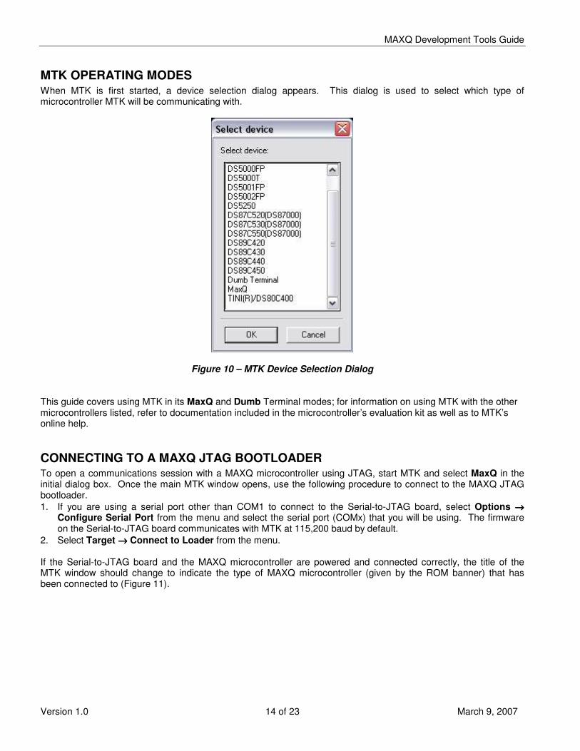
MTK OPERATING MODES When MTK is first started, a device selection dialog appears. This dialog is used to select which type of microcontroller MTK will be communicating with.
Figure 10 – MTK Device Selection Dialog
This guide covers using MTK in its MaxQ and Dumb Terminal modes; for information on using MTK with the other microcontrollers listed, refer to documentation included in the microcontroller’s evaluation kit as well as to MTK’s online help. CONNECTING TO A MAXQ JTAG BOOTLOADER To open a communications session with a MAXQ microcontroller using JTAG, start MTK and select MaxQ in the initial dialog box. Once the main MTK window opens, use the following procedure to connect to the MAXQ JTAG bootloader. 1. If you are using a serial port other than COM1 to connect to the Serial-to-JTAG board, select Options →→→→
Configure Serial Port from the menu and select the serial port (COMx) that you will be using. The firmware on the Serial-to-JTAG board communicates with MTK at 115,200 baud by default.
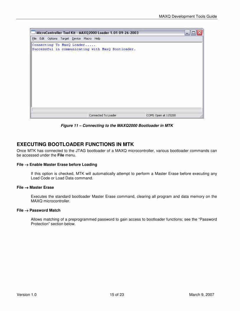
2. Select Target →→→→ Connect to Loader from the menu. If the Serial-to-JTAG board and the MAXQ microcontroller are powered and connected correctly, the title of the MTK window should change to indicate the type of MAXQ microcontroller (given by the ROM banner) that has been connected to (Figure 11).
MAXQ Development Tools Guide
Version 1.0 15 of 23 March 9, 2007
Figure 11 – Connecting to the MAXQ2000 Bootloader in MTK EXECUTING BOOTLOADER FUNCTIONS IN MTK Once MTK has connected to the JTAG bootloader of a MAXQ microcontroller, various bootloader commands can be accessed under the File menu. File →→→→ Enable Master Erase before Loading
If this option is checked, MTK will automatically attempt to perform a Master Erase before executing any Load Code or Load Data command.
File →→→→ Master Erase
Executes the standard bootloader Master Erase command, clearing all program and data memory on the MAXQ microcontroller.
File →→→→ Password Match
Allows matching of a preprogrammed password to gain access to bootloader functions; see the “Password Protection” section below.
MAXQ Development Tools Guide
Version 1.0 16 of 23 March 9, 2007
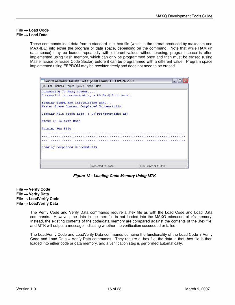
File →→→→ Load Code File →→→→ Load Data
These commands load data from a standard Intel hex file (which is the format produced by maxqasm and MAX-IDE) into either the program or data space, depending on the command. Note that while RAM (in data space) may be loaded repeatedly with different values without erasing, program space is often implemented using flash memory, which can only be programmed once and then must be erased (using Master Erase or Erase Code Sector) before it can be programmed with a different value. Program space implemented using EEPROM may be rewritten freely and does not need to be erased.
Figure 12 - Loading Code Memory Using MTK File →→→→ Verify Code File →→→→ Verify Data File →→→→ LoadVerify Code File →→→→ LoadVerify Data
The Verify Code and Verify Data commands require a .hex file as with the Load Code and Load Data commands. However, the data in the .hex file is not loaded into the MAXQ microcontroller’s memory. Instead, the existing contents of the code/data memory are compared against the contents of the .hex file, and MTK will output a message indicating whether the verification succeeded or failed. The LoadVerify Code and LoadVerify Data commands combine the functionality of the Load Code + Verify Code and Load Data + Verify Data commands. They require a .hex file; the data in that .hex file is then loaded into either code or data memory, and a verification step is performed automatically.

MAXQ Development Tools Guide
Version 1.0 17 of 23 March 9, 2007
File →→→→ Dump Code File →→→→ Dump Data
These commands allow the contents of code or data space to be read back from the MAXQ microcontroller by MTK. They require a starting address and length to be entered in a dialog; the format for this is either hex or decimal depending on the setting of the Device →→→→ Enter Addresses and Lengths in HEX menu option. Depending on the setting of Device →→→→ Dump Options, data dumped by these commands may be output in standard Intel hex format (default – Figure 13), mixed hex/ASCII format (Figure 14), or disassembled code format (Figure 15).
Figure 13 – Dump Code Command (Hex Format)
Figure 14 – Dump Code Command (Hex/ASCII Format)

MAXQ Development Tools Guide
Version 1.0 18 of 23 March 9, 2007
Figure 15 – Dump Code Command (Disassembly Mode) File →→→→ CRC Code File →→→→ CRC Data
These commands are also used to verify the existing contents of either code or data space. However, instead of comparing the memory contents against the contents of a .hex file, these commands calculate a CRC-16 value over a given memory range. This value is then output by MTK. These commands can also be used to determine if memory contents of a given device have been corrupted or otherwise altered.
File →→→→ Erase Code Sector File →→→→ Erase Data
These commands are designed to perform partial erases of code and data memory, respectively, without erasing the entire device. Behavior of these commands is highly part-dependent; refer to the User’s Guide Supplement for the device you are using for more details.

MAXQ Development Tools Guide
Version 1.0 19 of 23 March 9, 2007
PASSWORD PROTECTION IN MTK AND MAX-IDE Most MAXQ microcontrollers with rewriteable nonvolatile memory implement a basic password protection scheme. This password protection scheme, which relies on a password stored in main program memory, can be used to optionally restrict access to bootloader and debugging functions. The password is stored in 16 words (32 bytes) in program memory beginning at word address 0010h (byte address 0020h). Access to the bootloader is controlled by the password lock bit PWL (SC.1), which has the following effects. • If PWL=1, no debug mode commands may be accessed except for the Debug Match Password command. • If PWL=1, no bootloader commands may be accessed except for those in Family 0. • If PWL=0, all debugging and bootloader commands may be accessed. The password lock bit defaults to 1 (locked) on device powerup. It is also changed under the following circumstances. Password Bit is Locked (Set to 1) When • The bootloader is entered and program memory words 0010h through 001Fh contain a valid password (invalid
passwords are all 0000h values or all FFFFh values). • The Match Password bootloader command is executed and the password provided does not match the
password in program memory. • SC.1 is explicitly set to 1 by the application software or by the debugger. Note that setting PWL=1 while
debugging a project will cause the debugger to be immediately locked out; this can be easily demonstrated by setting SC.1 to 1 in MAX-IDE’s Registers window.
Password Bit is Unlocked (Cleared to 0) When • A Master Erase command is executed by the bootloader. • The bootloader is entered and program memory words 0010h through 001Fh contain an invalid password
(either all words are 0000h or all words are FFFFh). • A debug command is executed and program memory words 0010h through 001Fh contain an invalid password
(either all words are 0000h or all words are FFFFh). • The Match Password debug command is executed and the password provided matches the password in
program memory. • The Match Password bootloader command is executed and the password provided matches the password in
program memory. • SC.1 is explicitly cleared to 0 by application software. Default Password Protection If no special attention is paid to the password protection scheme, the password area (addresses 0010h through 001Fh) will most likely be filled with arbitrary code. This will result in a valid password value which, while not completely random, will be fairly difficult to guess, particularly if the code contains calls to arbitrary addresses or loads of arbitrary immediate values. Even though the password will contain a valid value, it will still be possible to debug the project during the development cycle. This is the case because when MAX-IDE (or another development environment) loads the project, it performs a Master Erase cycle. This causes the password bit to be cleared, and under normal circumstances the password bit will not be set again until a power-on reset occurs. This means that the debugger may be run normally, but once MAX-IDE is disconnected and the device is powered off and on again, the password bit will set and debugger and bootloader functions will no longer be accessible without first matching the password or erasing the device. It is possible to explicitly match the password later on using the appropriate bootloader or debugging command, to allow dumping of program or code memory without erasing the part. This can be done in MTK using the Match Password command and entering in the appropriate values from the project’s list or hex files.

MAXQ Development Tools Guide
Version 1.0 20 of 23 March 9, 2007
Disabling the Password By skipping over the password area using ORG statements in the assembler or by explicitly filling the password region with all 0000h or all FFFFh values, it is possible to ensure that the password will always be unlocked. This is particularly useful during development, when it may be helpful to dump program or data memory from a device that has been running an application for a while. org 0h ljump main org 0010h dw 0000h, 0000h, 0000h, 0000h, 0000h, 0000h, 0000h, 0000h dw 0000h, 0000h, 0000h, 0000h, 0000h, 0000h, 0000h, 0000h org 0020h main: .... org 0h ljump main org 0010h dw 0FFFFh, 0FFFFh, 0FFFFh, 0FFFFh, 0FFFFh, 0FFFFh, 0FFFFh, 0FFFFh dw 0FFFFh, 0FFFFh, 0FFFFh, 0FFFFh, 0FFFFh, 0FFFFh, 0FFFFh, 0FFFFh org 0020h main: ....
MAXQ Development Tools Guide
Version 1.0 21 of 23 March 9, 2007
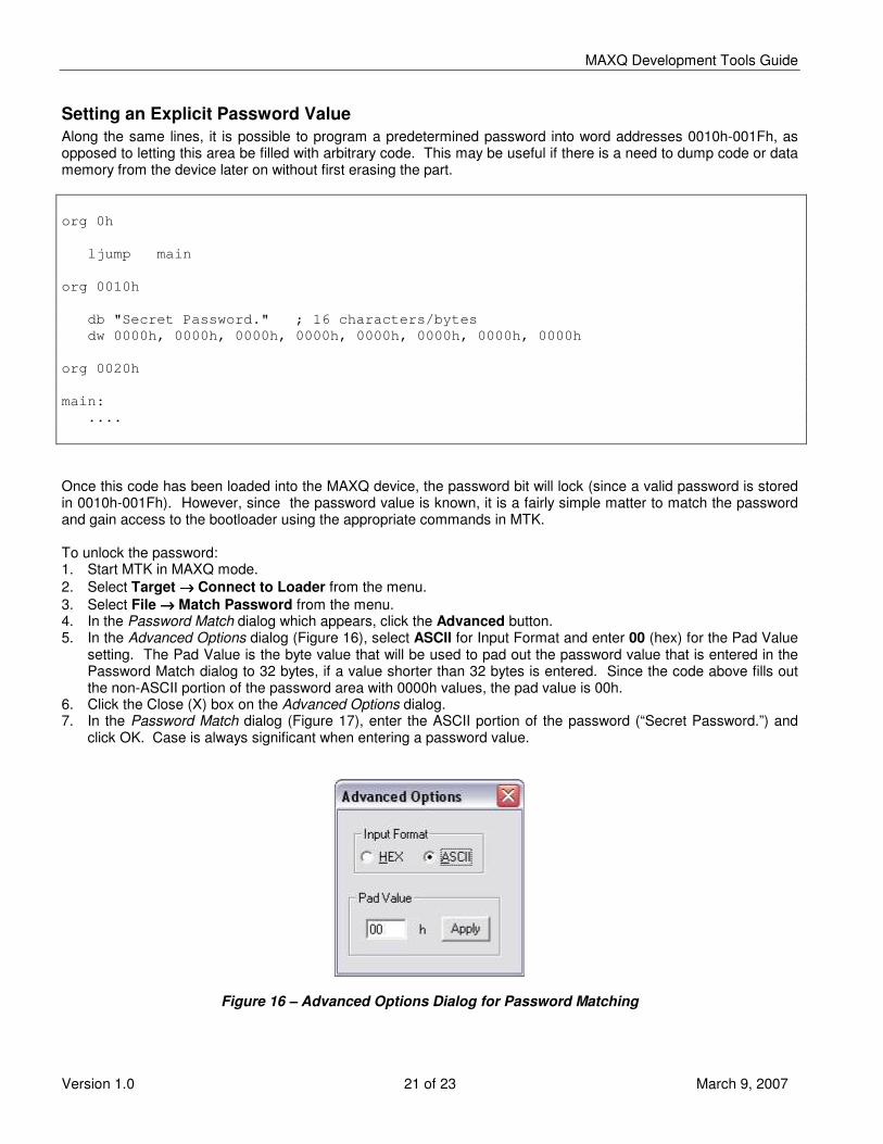
Setting an Explicit Password Value Along the same lines, it is possible to program a predetermined password into word addresses 0010h-001Fh, as opposed to letting this area be filled with arbitrary code. This may be useful if there is a need to dump code or data memory from the device later on without first erasing the part. org 0h ljump main org 0010h db "Secret Password." ; 16 characters/bytes dw 0000h, 0000h, 0000h, 0000h, 0000h, 0000h, 0000h, 0000h org 0020h main: .... Once this code has been loaded into the MAXQ device, the password bit will lock (since a valid password is stored in 0010h-001Fh). However, since the password value is known, it is a fairly simple matter to match the password and gain access to the bootloader using the appropriate commands in MTK. To unlock the password: 1. Start MTK in MAXQ mode. 2. Select Target →→→→ Connect to Loader from the menu. 3. Select File →→→→ Match Password from the menu. 4. In the Password Match dialog which appears, click the Advanced button. 5. In the Advanced Options dialog (Figure 16), select ASCII for Input Format and enter 00 (hex) for the Pad Value
setting. The Pad Value is the byte value that will be used to pad out the password value that is entered in the Password Match dialog to 32 bytes, if a value shorter than 32 bytes is entered. Since the code above fills out the non-ASCII portion of the password area with 0000h values, the pad value is 00h.
6. Click the Close (X) box on the Advanced Options dialog. 7. In the Password Match dialog (Figure 17), enter the ASCII portion of the password (“Secret Password.”) and
click OK. Case is always significant when entering a password value.
Figure 16 – Advanced Options Dialog for Password Matching

MAXQ Development Tools Guide
Version 1.0 22 of 23 March 9, 2007
Figure 17 – Password Match Dialog Once the password has been entered, the main MTK window should display a “Password Bit is reset” message. At this point, it will be possible to access the normal bootloader commands, dumping data or code memory as shown below.
Figure 18 – Unlocking Password and Dumping Code Memory

MAXQ Development Tools Guide
Version 1.0 23 of 23 March 9, 2007
REVISION HISTORY
Version Date Changes
1.0 03/09/2007 • Original release covering MAX-IDE and MTK.