maxon motor control - servo.com.sg · maxon motor control maxon motor control various 4-quadrant...
TRANSCRIPT
423
424–428429–430
NEW 431–435436–438
NEW 439–444 445–447
448449–450
max
on
mo
tor
cont
rol
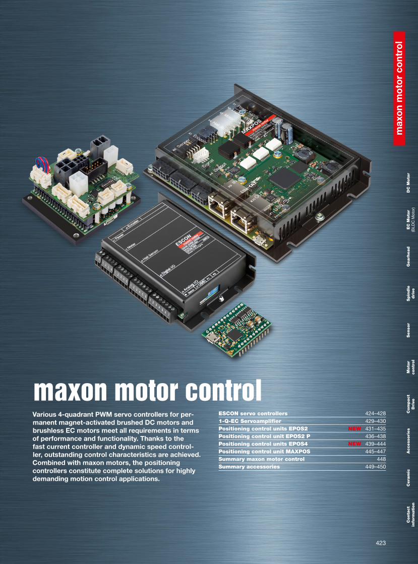
maxon motor control Various 4-quadrant PWM servo controllers for per-manent magnet-activated brushed DC motors and brushless EC motors meet all requirements in terms of performance and functionality. Thanks to the fast current controller and dynamic speed control-ler, outstanding control characteristics are achieved. Combined with maxon motors, the positioning controllers constitute complete solutions for highly demanding motion control applications.
ESCON servo controllers1-Q-EC ServoamplifierPositioning control units EPOS2Positioning control unit EPOS2 PPositioning control units EPOS4Positioning control unit MAXPOSSummary maxon motor controlSummary accessories
DC
Moto
r E
C M
oto
r(B
LDC
Mot
or)
Gearh
ead
Spin
dle
dri
veSenso
r M
oto
r
contr
ol
Com
pact
Dri
veA
ccess
ori
es
Cera
mic
C
onta
ct
info
rmati
on
424
max
on
mo
tor
cont
rol
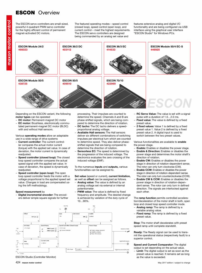
ESCON Module 50/5 438725
ESCON 50/5 409510
ESCON 70/10 422969
ESCON Module 24/2 466023
ESCON 36/2 DC 403112
ESCON 36/3 EC 414533
ESCON Module 50/4 EC-S 446925
ESCON
maxon motor control May 2017 edition / subject to change
ESCON Overview
The ESCON servo controllers are small-sized, powerful 4-quadrant PWM servo controller for the highly efficient control of permanent magnet-activated DC motors.
The featured operating modes – speed control (closed loop), speed control (open loop), and current control – meet the highest requirements. The ESCON servo controllers are designed being commanded by an analog set value and
features extensive analog and digital I/O functionality and are being configured via USB interface using the graphical user interface “ESCON Studio” for Windows PCs.
Depending on the ESCON variant, the following motor types can be operated
− DC motor: Permanent-magnet DC motor − EC motor: Brushless, electronically commu-tated permanent-magnet DC motor (BLDC) with and without Hall sensors.
Various operating modes allow an adaptable use in a wide range of drive systems
− Current controller: The current control-ler compares the actual motor current (torque) with the applied set value. In case of deviation, the motor current is dynamically readjusted.
− Speed controller (closed loop): The closed loop speed controller compares the actual speed signal with the applied set value. In case of deviation, the speed is dynamically readjusted.
− Speed controller (open loop): The open loop speed controller feeds the motor with a voltage proportional to the applied speed set value. Changes in load are compensated us-ing the IxR methodology.
Speed measurement by − Digital incremental encoder: The encod-ers deliver simple square signals for further
processing. Their impulses are counted to determine the speed. Channels A and B are phase-shifted signals, which are being com-pared to determine the direction of rotation.
− DC tacho: The DC tacho delivers a speed-proportional analog voltage.
− Available Hall sensors: The Hall sensors deliver six different combinations of switching impulses per electrical turn which are counted to determine speed. They also deliver phase-shifted signals that are being compared to determine the direction of rotation.
− Sensorless EC: The speed is determined by the progression of the induced voltage. The electronics evaluates the zero crossing of the induced voltage (EMF).
To the numerous inputs and outputs, various functionalities can be assigned to.
Set value (speed or current), current limitation, as well as offset can be assigned as follows.
− Analog value: The value is defined by an analog voltage set via external or internal potentiometer.
− PWM value: The value is defined by fixed frequency and amplitude. The desired change is achieved by variation of the duty cycle of 10…90%.
− RC Servo Value: The value is set with a signal pulse with a duration of 1.0…2.0 ms.
− Fixed value: The value is defined by a fixed preset value.
− 2 fixed values: Value 1 is defined by a fixed preset value 1. Value 2 is defined by a fixed preset value 2. A digital input is used to switch between the two preset values.
Various functionalities are available to enable the power stage.
− Enable: Enables or disables the power stage. − Enable & Direction: Enables or disables the power stage and determines the motor shaft’s direction of rotation.
− Enable CW: Enables or disables the power stage in direction of rotation-dependent sense. The rotor can only turn clockwise (CW).
− Enable CCW: Enables or disables the power stage in direction of rotation-dependent sense. The rotor can only turn counterclockwise (CCW).
− Enable CW & CCW: Enables or disables the power stage in direction of rotation-depen-dent sense. The rotor can only turn in defined direction. The signals are interlocked against each other.
The ramp function permits controlled accelera-tion/deceleration of the motor shaft in both, open loop and closed loop speed controller mode.
− Analog ramp: The ramp is defined by a variable analog value.
− Fixed ramp: The ramp is defined by a fixed preset value.
Stop: The motor shaft decelerates with preset speed ramp until complete standstill.
Ready: The Ready signal can be used to trans-mit the operational status (respectively fault) to a superior control.
Speed and Current Comparator: The digital output is set depending on the actual value.
− Limit: The digital output is set as soon as the preset value is reached. It remains set as long as the value is exceeded.ESCON Studio (Controller Monitor)

425
max
on
mo
tor
cont
rol
M 24/2 36/2 DC 36/3 EC M 50/4 EC-S M 50/5 50/5 70/10404404 ESCON 36/2 DC Connector Set — — — — — —425255 ESCON 36/3 EC Connector Set — — — — — —403962 DC Motor Cable — — — — — —403964 I/O Cable 7core — — — — —403965 I/O Cable 6core — — — — —275934 Encoder Cable — — — —
403957 Power Cable — — — — —403968 USB Type A - micro B Cable
418719 Adapter BLACK FPC11poles — — — — — —418723 Adapter BLUE FPC8poles — — — — — —418721 Adapter GREEN FPC8poles — — — — — —486400 ESCON Module 24/2 Motherboard — — — — — —438779 ESCON Module Motherboard — — — — — —450237 ESCON Module Motherboard Sensorless — — — — — —409286 ESCON USB Stick
May 2017 edition / subject to change maxon motor control
SoftwareInstallation Program: ESCON SetupGraphical User Interface: ESCON Studio Startup Wizard Regulation Tuning Diagnostic Firmware Update Controller Monitor Parameters Data Recording Online HelpLanguage: German, English, French, Italian, Spanish, Japanese, ChineseOperating System: Windows 10, Windows 8, Windows 7, Windows XP SP3Communication interface: USB 2.0/3.0 (full speed)
Easy startupStartup and parameterization are performed using the intuitive graphical user interface “ ESCON Studio” with the help of simple to use, menu-guided wizards. The following wizards are available: Startup, Regulation Tuning, Firmware Update, Controller Monitor, Parameters, Data Recording, and Diagnostics.
Protective equipment The servo controller has protective circuits against overcurrent, excess temperature, under- and overvoltage, against voltage transients, and against short-circuits in the motor cable. Further-more it is equipped with protected digital inputs and outputs and an adjustable current limitation for protecting the motor and the load. The motor current and the actual speed of the motor shaft can be monitored by means of the analog output voltage.
Comprehensive documentationUsing the “Feature Comparison Chart”, the suitable ESCON servo controller can easily be determined. The “Hardware Reference” comprises the specifications of the hardware in detail. The documents “Firmware Version” and “Release Notes” describe changes and improvements of firmware and software. In addition, the graphical user interface “ESCON Studio” features a comprehensive online help.
− Range: The digital output is set as soon as the preset value range is reached. It remains set as long as the value remains in range.
− Deviation: The digital output is set as soon as the preset value deviation (based on the set value) is in range.
With the integrated potentiometers the addi-tional following functions can be adjusted
− Current Gain: Adjustment of the current controller gain.
− Speed Gain: Adjustment of the speed controller gain.
− IxR Factor: The voltage drop caused by ter-minal resistance will be compensated in the range of [0…1000…2000].
Analog outputs allow monitoring of − Actual current: Actually measured motor winding current.
− Actual current averaged: Actually measured motor winding current filtered by first order digital low-pass filter with a cut-off frequency of 5 Hz.
− Actual speed: Actually measured motor speed.
− Actual speed averaged: Actually measured motor speed filtered by 1st order digital low-pass filter with a cut-off frequency of 5 Hz.
− Demand Current: Demanded motor winding current.
− Demand Speed: Demanded motor speed. − Temperature Power Stage: Actually measured power stage temperature.
− Fixed value: The output voltage is said fixed to the preset value.
Accessories ESCON*
(analog I/O’s) (digital I/O’s)
*not included in delivery

426
max
on
mo
tor
cont
rol
maxon motor control May 2017 edition / subject to change
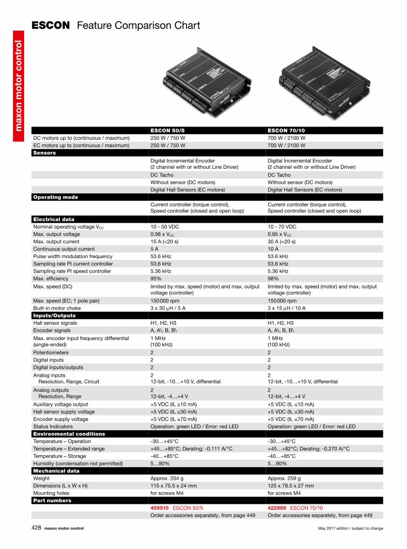
ESCON Feature Comparison Chart
DC motors up to (continuous / maximum)EC motors up to (continuous / maximum)Sensors
Operating mode
Electrical dataNominal operating voltage VCC
Max. output voltageMax. output currentContinuous output currentPulse width modulation frequencySampling rate PI current controllerSampling rate PI speed controllerMax. efficiencyMax. speed (DC)
Max. speed (EC; 1 pole pair)Built-in motor chokeInputs/OutputsHall sensor signalsEncoder signalsMax. encoder input frequency differential (single-ended)
PotentiometersDigital inputsDigital inputs/outputsAnalog inputs Resolution, Range, Circuit
Analog outputs Resolution, RangeAuxiliary voltage outputHall sensor supply voltageEncoder supply voltageStatus IndicatorsEnvironmental conditionsTemperature – OperationTemperature – Extended rangeTemperature – StorageHumidity (condensation not permitted)Mechanical dataWeightDimensions (L x W x H)Mounting holesPart numbers
ESCON Module 24/248 W / 144 W48 W / 144 W
Digital Incremental Encoder (2 channel with or without Line Driver)DC TachoWithout sensor (DC motors)Digital Hall Sensors (EC motors)
Current controller (torque control), Speed controller (closed and open loop)
10 - 24 VDC0.98 x VCC
6 A (<4 s)2 A53.6 kHz53.6 kHz5.36 kHz92%limited by max. speed (motor) and max. output voltage (controller)
150 000 rpm–
H1, H2, H3A, A\, B, B\1 MHz (100 kHz)–222 12-bit, -10…+10 V, differential
2 12-bit, -4…+4 V+5 VDC (IL ≤10 mA)+5 VDC (IL ≤30 mA)+5 VDC (IL ≤70 mA)Operation: green LED / Error: red LED
-30…+60°C+60…+80°C; Derating: -0.100 A/°C-40…+85°C5…90%
Approx. 7 g35.6 x 26.7 x 12.7 mmPlugable (socket headers with 2.54 mm pitch)
466023 ESCON Module 24/2Order accessories separately, from page 449
ESCON 36/2 DC72 W / 144 W–
Digital Incremental Encoder (2 channel with or without Line Driver)DC TachoWithout sensor (DC motors)–
Current controller (torque control), Speed controller (closed and open loop)
10 - 36 VDC0.98 x VCC
4 A (<60 s)2 A53.6 kHz53.6 kHz5.36 kHz95%limited by max. speed (motor) and max. output voltage (controller)
–300 mH / 2 A
–A, A\, B, B\1 MHz (100 kHz)1222 12-bit, -10…+10 V, differential
2 12-bit, -4…+4 V+5 VDC (IL ≤10 mA)–+5 VDC (IL ≤70 mA)Operation: green LED / Error: red LED
-30…+45°C+45…+81°C; Derating: -0.056 A/°C-40…+85°C5…90%
Approx. 30 g55.0 x 40.0 x 16.1 mmfor screws M2.5
403112 ESCON 36/2 DCOrder accessories separately, from page 449

427
max
on
mo
tor
cont
rol
May 2017 edition / subject to change maxon motor control
ESCON Feature Comparison Chart
ESCON Module 50/4 EC-S–200 W / 600 W
–
–Without sensor (EC motors)–
Speed controller (closed and open loop)
10 - 50 VDC0.96 x VCC
12 A (<30 s)4 A53.6 kHz–5.36 kHz97%–
120 000 rpm–
–––
1222 12-bit, -10…+10 V, differential
2 12-bit, -4…+4 V+5 VDC (IL ≤110 mA)––Operation: green LED / Error: red LED
-30…+45°C+45…+65°C; Derating -0.200 A/°C-40…+85°C5…90%
Approx. 11 g43.2 x 31.8 x 12.7 mmPlugable (socket headers with 2.54 mm pitch)
446925 ESCON Module 50/4 EC-SOrder accessories separately, from page 449
ESCON Module 50/5250 W / 750 W250 W / 750 W
Digital Incremental Encoder (2 channel with or without Line Driver)DC TachoWithout sensor (DC motors)Digital Hall Sensors (EC motors)
Current controller (torque control), Speed controller (closed and open loop)
10 - 50 VDC0.98 x VCC
15 A (<20 s)5 A53.6 kHz53.6 kHz5.36 kHz98%limited by max. speed (motor) and max. output voltage (controller)150 000 rpm–
H1, H2, H3A, A\, B, B\1 MHz (100 kHz)1222 12-bit, -10…+10 V, differential
2 12-bit, -4…+4 V+5 VDC (IL ≤10 mA)+5 VDC (IL ≤30 mA)+5 VDC (IL ≤70 mA)Operation: green LED / Error: red LED
-30…+45°C+45…+75°C; Derating: -0.167 A/°C-40…+85°C5…90%
Approx. 12 g43.2 x 31.8 x 12.7 mmPlugable (socket headers with 2.54 mm pitch)
438725 ESCON Module 50/5Order accessories separately, from page 449
ESCON 36/3 EC
97 W / 324 WSensors
–
––Digital Hall Sensors (EC motors)Operating modeCurrent controller (torque control), Speed controller (closed and open loop)
Electrical data10 - 36 VDC0.98 x VCC
9 A (<4 s)2.7 A53.6 kHz53.6 kHz5.36 kHz95%–
150 000 rpm3 x 47 mH / 2.7 AInputs/OutputsH1, H2, H3––
1222 12-bit, -10…+10 V, differential
2 12-bit, -4…+4 V+5 VDC (IL ≤10 mA)+5 VDC (IL ≤30 mA)–Operation: green LED / Error: red LEDEnvironmental conditions-30…+45°C+45…+78°C; Derating: -0.082 A/°C-40…+85°C5…90%Mechanical dataApprox. 36 g55.0 x 40.0 x 19.8 mmfor screws M2.5Part numbers414533 ESCON 36/3 ECOrder accessories separately, from page 449
428
max
on
mo
tor
cont
rol
maxon motor control May 2017 edition / subject to change
ESCON Feature Comparison Chart
DC motors up to (continuous / maximum)EC motors up to (continuous / maximum)Sensors
Operating mode
Electrical dataNominal operating voltage VCC
Max. output voltageMax. output currentContinuous output currentPulse width modulation frequencySampling rate PI current controllerSampling rate PI speed controllerMax. efficiencyMax. speed (DC)
Max. speed (EC; 1 pole pair)Built-in motor chokeInputs/OutputsHall sensor signalsEncoder signalsMax. encoder input frequency differential (single-ended)
PotentiometersDigital inputsDigital inputs/outputsAnalog inputs Resolution, Range, Circuit
Analog outputs Resolution, RangeAuxiliary voltage outputHall sensor supply voltageEncoder supply voltageStatus IndicatorsEnvironmental conditionsTemperature – OperationTemperature – Extended rangeTemperature – StorageHumidity (condensation not permitted)Mechanical dataWeightDimensions (L x W x H)Mounting holesPart numbers
ESCON 70/10700 W / 2100 W700 W / 2100 W
Digital Incremental Encoder (2 channel with or without Line Driver)DC TachoWithout sensor (DC motors)Digital Hall Sensors (EC motors)
Current controller (torque control), Speed controller (closed and open loop)
10 - 70 VDC0.95 x VCC
30 A (<20 s)10 A53.6 kHz53.6 kHz5.36 kHz98%limited by max. speed (motor) and max. output voltage (controller)150 000 rpm3 x 15 mH / 10 A
H1, H2, H3A, A\, B, B\1 MHz (100 kHz)2222 12-bit, -10…+10 V, differential
2 12-bit, -4…+4 V+5 VDC (IL ≤10 mA)+5 VDC (IL ≤30 mA)+5 VDC (IL ≤70 mA)Operation: green LED / Error: red LED
-30…+45°C+45…+82°C; Derating: -0.270 A/°C-40…+85°C5…90%
Approx. 259 g125 x 78.5 x 27 mmfor screws M4
422969 ESCON 70/10Order accessories separately, from page 449
ESCON 50/5250 W / 750 W250 W / 750 W
Digital Incremental Encoder (2 channel with or without Line Driver)DC TachoWithout sensor (DC motors)Digital Hall Sensors (EC motors)
Current controller (torque control), Speed controller (closed and open loop)
10 - 50 VDC0.98 x VCC
15 A (<20 s)5 A53.6 kHz53.6 kHz5.36 kHz95%limited by max. speed (motor) and max. output voltage (controller)150 000 rpm3 x 30 mH / 5 A
H1, H2, H3A, A\, B, B\1 MHz (100 kHz)2222 12-bit, -10…+10 V, differential
2 12-bit, -4…+4 V+5 VDC (IL ≤10 mA)+5 VDC (IL ≤30 mA)+5 VDC (IL ≤70 mA)Operation: green LED / Error: red LED
-30…+45°C+45…+85°C; Derating: -0.111 A/°C-40…+85°C5…90%
Approx. 204 g115 x 75.5 x 24 mmfor screws M4
409510 ESCON 50/5Order accessories separately, from page 449