maximum cable and hose diameters distribution within the ...€¦ · igus ® energy chain systems...
TRANSCRIPT
Inte
rnet
: h
ttp
://w
ww
.igu
s.co
m
emai
l: sa
les@
igu
s.co
m
Qu
ickS
pec
: h
ttp
://w
ww
.igu
s.co
m/q
s/ch
ain
flex
.asp
igu
s®E
ner
gy
Ch
ain
Sys
tem
s®
10.18
Tele
ph
on
e1-
800-
521-
2747
Fax
1-
401-
438-
7270
In addition to the quality of the cables used, the arrangement of each cable/hosewithin the chain and the space allowed, are important for the service life of the system.Various separation options enable the adaptation of the Energy Chains® to the specificrequirements of each respective application. General rules of thumb, such as “maximum80% of the cross section of an Energy Chain should be used” are no longer viablewith today’s application complexities. In this chapter, we give you detailedrecommendations. Due to the variety of the application parameters, we stronglyrecommend you take advantage of our free consultation services. Simply give us alist of your cable requirements (or merely the required electrical or other services) andyou will receive our recommendation by the end of the next business day.
Maximum cable and hose diameters
The maximum cable and/or hose diameter corresponds to the inner height ofthe selected Energy Chain®/Tube, with additional minimum clearance. This minimumclearance would be, for example, 10% for electrical round cables, 20% forhydraulic hoses. An Energy Chain® is ideal if a minimum lateral gap to the nextcable or hose has been factored in. Depending on the nature of the cables, thedynamics, and the expected service life, more clearance must be allowed. Inspecific cases, clearances may be altered further. Please consult igus®.
Supply of data and energy in all forms within an Energy Chain System®
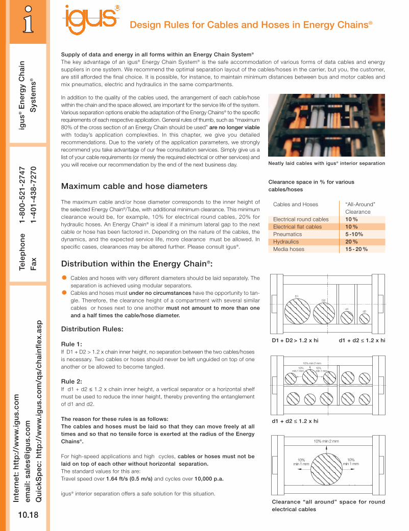
The key advantage of an igus® Energy Chain System® is the safe accommodation of various forms of data cables and energysuppliers in one system. We recommend the optimal separation layout of the cables/hoses in the carrier, but you, the customer,are still afforded the final choice. It is possible, for instance, to maintain minimum distances between bus and motor cables andmix pneumatics, electric and hydraulics in the same compartments.
Neatly laid cables with igus® interior separation
Design Rules for Cables and Hoses in Energy Chains®
Distribution Rules:
Rule 1:If D1 + D2 > 1.2 x chain inner height, no separation between the two cables/hosesis necessary. Two cables or hoses should never be left unguided on top of oneanother or be allowed to become tangled.
Rule 2:If d1 + d2 ≤ 1.2 x chain inner height, a vertical separator or a horizontal shelfmust be used to reduce the inner height, thereby preventing the entanglementof d1 and d2.
The reason for these rules is as follows:The cables and hoses must be laid so that they can move freely at alltimes and so that no tensile force is exerted at the radius of the EnergyChains®.
For high-speed applications and high cycles, cables or hoses must not belaid on top of each other without horizontal separation.The standard values for this are:Travel speed over 1.64 ft/s (0.5 m/s) and cycles over 10,000 p.a.
igus® interior separation offers a safe solution for this situation.
D1 + D2 > 1.2 x hi d1 + d2 ≤ 1.2 x hi
Distribution within the Energy Chain®:
D1D2
d1d2
d1 + d2 ≤ 1.2 x hi
Clearance “all around” space for roundelectrical cables
10% min 2 mm
10%min 1 mm
10%min 1 mm
10% min 2 mm
10%min 1 mm
10%min 1 mm
• Cables and hoses with very different diameters should be laid separately. Theseparation is achieved using modular separators.
• Cables and hoses must under no circumstances have the opportunity to tan-gle. Therefore, the clearance height of a compartment with several similarcables or hoses next to one another must not amount to more than oneand a half times the cable/hose diameter.
Clearance space in % for variouscables/hoses
Cables and Hoses “All-Around”Clearance
Electrical round cables 10 %Electrical flat cables 10 %Pneumatics 5 -10%Hydraulics 20 %Media hoses 15 - 20 %
PD
F:
ww
w.ig
us.
com
/pd
f/ch
ain
flex
.asp
Sp
ecs/
CA
D/R
FQ
: w
ww
.igu
s.co
m/c
hai
nfl
ex.a
sp
Ro
HS
info
: w
ww
.igu
s.co
m/R
oH
S.a
sp
igu
s®E
ner
gy
Ch
ain
Sys
tem
s®
Tele
ph
on
e1-
800-
521-
2747
Fax
1-
401-
438-
7270
10.19
Design Rules for Distribution of Cables/Hoses:
The cable or hose weight should be symmetrically distributed along the widthof the chain
• Cables and hoses with different outer jacket materials must not be allowedto “stick” together. If necessary, they must be laid separately. All igus®
Chainflex® cables can be combined with each other and all other brands ofcable or hose
• The cables and hoses should always be fixed at the moving end. The fixedend should always involve strain relief. Exceptions are made only for certainhydraulic hoses with length compensation issues or other high pressurehoses (i.e. hydraulic hoses)
• Generally, the faster and more frequently the Energy Chain® operates, themore important the exact positioning of the cables and hoses inside thechain. Due to the wide variety of the possibilities, we strongly recommendyou take advantage of our free consultation services for your specificapplications
Bending radius R• The bending radius of our Energy Chain® depends on the “thickest” or
“stiffest” cable or hose in your application
• The bending radii of the Energy Chains® should be adjusted to therecommendations of the cable or hose manufacturer. The selection of alarger radius than the minimum will positively affect service life
• The specification of minimum bending radii for cables and hoses refers touse at normal temperatures; other bending radii may be recommended.Please ask your cable or hose supplier for details
We recommend complete Energy Chain Systems® where bending radii for allcables and hoses, interior separation and service life are optimally matched.Please ask for the igus® System Guarantee.
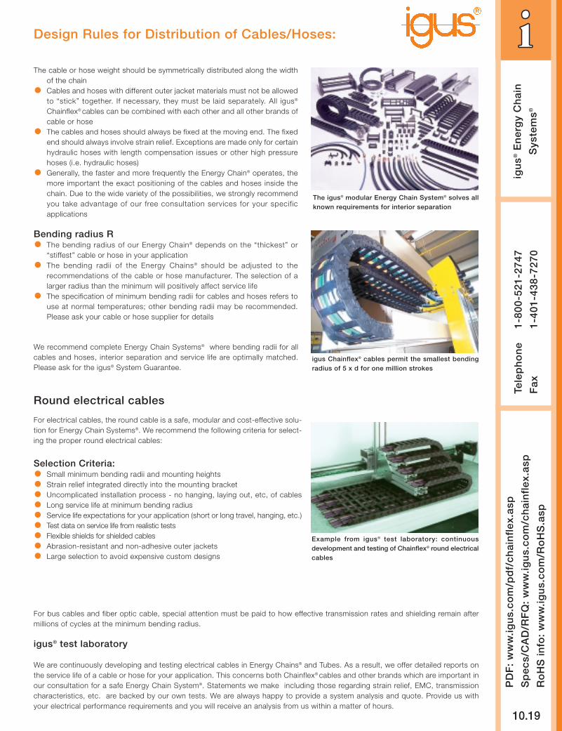
The igus® modular Energy Chain System® solves allknown requirements for interior separation
igus Chainflex® cables permit the smallest bendingradius of 5 x d for one million strokes
Round electrical cables
Selection Criteria:• Small minimum bending radii and mounting heights
• Strain relief integrated directly into the mounting bracket
• Uncomplicated installation process - no hanging, laying out, etc, of cables
• Long service life at minimum bending radius
• Service life expectations for your application (short or long travel, hanging, etc.)
• Test data on service life from realistic tests
• Flexible shields for shielded cables
• Abrasion-resistant and non-adhesive outer jackets
• Large selection to avoid expensive custom designs
For bus cables and fiber optic cable, special attention must be paid to how effective transmission rates and shielding remain aftermillions of cycles at the minimum bending radius.
igus® test laboratory
We are continuously developing and testing electrical cables in Energy Chains® and Tubes. As a result, we offer detailed reports onthe service life of a cable or hose for your application. This concerns both Chainflex® cables and other brands which are important inour consultation for a safe Energy Chain System®. Statements we make including those regarding strain relief, EMC, transmissioncharacteristics, etc. are backed by our own tests. We are always happy to provide a system analysis and quote. Provide us withyour electrical performance requirements and you will receive an analysis from us within a matter of hours.
For electrical cables, the round cable is a safe, modular and cost-effective solu-tion for Energy Chain Systems®. We recommend the following criteria for select-ing the proper round electrical cables:
Example from igus® test laboratory: continuousdevelopment and testing of Chainflex® round electricalcables
Inte
rnet
: h
ttp
://w
ww
.igu
s.co
m
emai
l: sa
les@
igu
s.co
m
Qu
ickS
pec
: h
ttp
://w
ww
.igu
s.co
m/q
s/ch
ain
flex
.asp
igu
s®E
ner
gy
Ch
ain
Sys
tem
s®
10.20
Tele
ph
on
e1-
800-
521-
2747
Fax
1-
401-
438-
7270
Guidelines for the installation and strain relief of round electrical cables
Correct!
1. The cables must be laid straight, without twisting. Cables must not be uncoiled from the top of the spool. igus® Chainflex®
cables are immediately ready for placement directly into the Energy Chain®. They need not be disconnected or laid out beforeinstallation.
2. The cables must be laid so that each individual cable can move freely from side to side.3. The cables must be able to move freely along the radius. This must be double-checked if the upper run operates at the cable’s
maximum bending radius.4. The division of the carrier’s interior using shelves or igus® interior separators is necessary if several cables and/or hoses with vary-
ing diameters are laid out. It is important to prevent cables and hoses from tangling.5. For cables and hoses with different jacket materials, it is important to prevent them from “sticking” to one another. If necessary,
they should be separated. igus® Chainflex® cables can be combined with all others.6. Round electrical cables must be secured with strain relief at both ends. In exceptional cases, the cables may be fixed with strain
relief at the moving end of the Energy Chain® only. A gap of 10-30 x cable diameter between the end of the bending segmentand the fixed point is recommended for most cables. Chainflex® cables can, on the other hand, be secured directly to the mount-ing bracket with strain relief (this has been confirmed with testing).
We are happy to offer a pre-assembled Energy Chain System®: the igus® “Triple Guarantee” of chain and cable, pre-assembled andfully harnessed.
Wrong!
Wrong!
Chainflex® cables can be strain-relieveddirectly at the mounting bracket
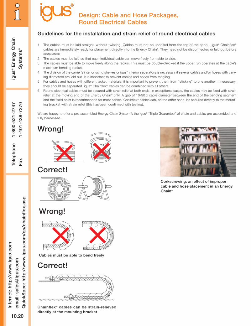
Corkscrewing: an effect of impropercable and hose placement in an EnergyChain®
Cables must be able to bend freely
Correct!
Design: Cable and Hose Packages,Round Electrical Cables
PD
F:
ww
w.ig
us.
com
/pd
f/ch
ain
flex
.asp
Sp
ecs/
CA
D/R
FQ
: w
ww
.igu
s.co
m/c
hai
nfl
ex.a
sp
Ro
HS
info
: w
ww
.igu
s.co
m/R
oH
S.a
sp
igu
s®E
ner
gy
Ch
ain
Sys
tem
s®
Tele
ph
on
e1-
800-
521-
2747
Fax
1-
401-
438-
7270
10.21
Design: Cable and Hose Packages,Flat Cables and Pneumatic Hoses
Flat cablesFlat cables must be able to move freely along the bending radius. Two flat cables next to one another should be kept apart with separators.If two flat cables are laid on top of one another, we strongly recommend the use of horizontal igus® shelving. Flat and round cablesshould be laid separately in the Energy Chain®. Strain relief should be attached at both ends. Flat cables are only conditionally recommendedfor use in Energy Chains®.
Outer jackets made of rubber must be specified particularly carefully, because of potentially high static friction.
Pneumatic hoses
In principle, the same rules apply for pneumatic hoses as for round cables. In practice, it has been demonstrated that pneumatic hosesare less susceptible to wear. After consultation, they can be laid together more closely than the “10% clearance all-around” rule. Adouble-sided strain relief is required under these conditions. For pneumatic hoses made of rubber, we recommend strictly following the“10% clearance” rule because they tend to adhere to each other and to other cables/hoses.
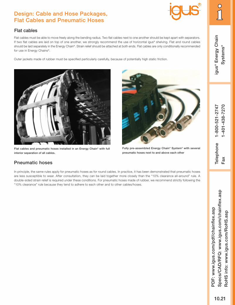
Fully pre-assembled Energy Chain® System® with several
pneumatic hoses next to and above each other
Flat cables and pneumatic hoses installed in an Energy Chain® with full
interior separation of all cables.
Inte
rnet
: h
ttp
://w
ww
.igu
s.co
m
emai
l: sa
les@
igu
s.co
m
Qu
ickS
pec
: h
ttp
://w
ww
.igu
s.co
m/q
s/ch
ain
flex
.asp
igu
s®E
ner
gy
Ch
ain
Sys
tem
s®
10.22
Tele
ph
on
e1-
800-
521-
2747
Fax
1-
401-
438-
7270
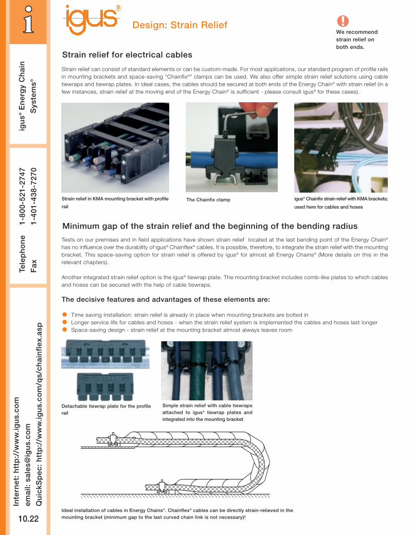
Design: Strain Relief
igus® Chainfix strain relief with KMA brackets;
used here for cables and hoses
Strain relief can consist of standard elements or can be custom-made. For most applications, our standard program of profile railsin mounting brackets and space-saving “Chainfix®” clamps can be used. We also offer simple strain relief solutions using cabletiewraps and tiewrap plates. In ideal cases, the cables should be secured at both ends of the Energy Chain® with strain relief (in afew instances, strain relief at the moving end of the Energy Chain® is sufficient - please consult igus® for these cases).
Strain relief in KMA mounting bracket with profile
railThe Chainfix clamp
Strain relief for electrical cables
We recommendstrain relief onboth ends.
Minimum gap of the strain relief and the beginning of the bending radius
Tests on our premises and in field applications have shown strain relief located at the last bending point of the Energy Chain®
has no influence over the durability of igus® Chainflex® cables. It is possible, therefore, to integrate the strain relief with the mountingbracket. This space-saving option for strain relief is offered by igus® for almost all Energy Chains® (More details on this in therelevant chapters).
Another integrated strain relief option is the igus® tiewrap plate. The mounting bracket includes comb-like plates to which cablesand hoses can be secured with the help of cable tiewraps.
The decisive features and advantages of these elements are:
• Time saving installation: strain relief is already in place when mounting brackets are bolted in
• Longer service life for cables and hoses - when the strain relief system is implemented the cables and hoses last longer
• Space-saving design - strain relief at the mounting bracket almost always leaves room
Ideal installation of cables in Energy Chains®. Chainflex® cables can be directly strain-relieved in themounting bracket (minimum gap to the last curved chain link is not necessary)!
Detachable tiewrap plate for the profilerail
Simple strain relief with cable tiewrapsattached to igus® tiewrap plates andintegrated into the mounting bracket
PD
F:
ww
w.ig
us.
com
/pd
f/ch
ain
flex
.asp
Sp
ecs/
CA
D/R
FQ
: w
ww
.igu
s.co
m/c
hai
nfl
ex.a
sp
Ro
HS
info
: w
ww
.igu
s.co
m/R
oH
S.a
sp
igu
s®E
ner
gy
Ch
ain
Sys
tem
s®
Tele
ph
on
e1-
800-
521-
2747
Fax
1-
401-
438-
7270
10.23
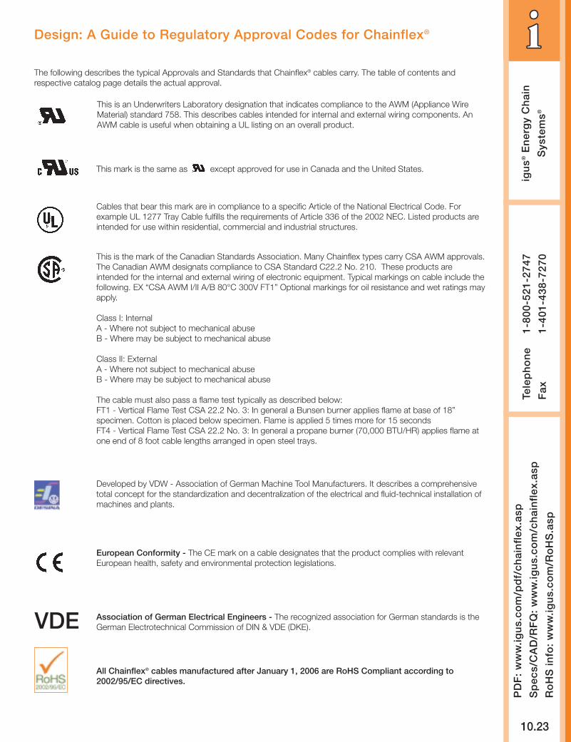
Design: A Guide to Regulatory Approval Codes for Chainflex®
The following describes the typical Approvals and Standards that Chainflex® cables carry. The table of contents andrespective catalog page details the actual approval.
This is an Underwriters Laboratory designation that indicates compliance to the AWM (Appliance WireMaterial) standard 758. This describes cables intended for internal and external wiring components. AnAWM cable is useful when obtaining a UL listing on an overall product.
This mark is the same as except approved for use in Canada and the United States.
Cables that bear this mark are in compliance to a specific Article of the National Electrical Code. Forexample UL 1277 Tray Cable fulfills the requirements of Article 336 of the 2002 NEC. Listed products areintended for use within residential, commercial and industrial structures.
Developed by VDW - Association of German Machine Tool Manufacturers. It describes a comprehensivetotal concept for the standardization and decentralization of the electrical and fluid-technical installation ofmachines and plants.
European Conformity - The CE mark on a cable designates that the product complies with relevantEuropean health, safety and environmental protection legislations.
Association of German Electrical Engineers - The recognized association for German standards is theGerman Electrotechnical Commission of DIN & VDE (DKE).VDE
All Chainflex® cables manufactured after January 1, 2006 are RoHS Compliant according to2002/95/EC directives.
This is the mark of the Canadian Standards Association. Many Chainflex types carry CSA AWM approvals.The Canadian AWM designats compliance to CSA Standard C22.2 No. 210. These products areintended for the internal and external wiring of electronic equipment. Typical markings on cable include thefollowing. EX “CSA AWM I/II A/B 80°C 300V FT1” Optional markings for oil resistance and wet ratings mayapply.
Class I: InternalA - Where not subject to mechanical abuseB - Where may be subject to mechanical abuse
Class II: ExternalA - Where not subject to mechanical abuseB - Where may be subject to mechanical abuse
The cable must also pass a flame test typically as described below:FT1 - Vertical Flame Test CSA 22.2 No. 3: In general a Bunsen burner applies flame at base of 18”specimen. Cotton is placed below specimen. Flame is applied 5 times more for 15 secondsFT4 - Vertical Flame Test CSA 22.2 No. 3: In general a propane burner (70,000 BTU/HR) applies flame atone end of 8 foot cable lengths arranged in open steel trays.
Inte
rnet
: h
ttp
://w
ww
.igu
s.co
m
emai
l: sa
les@
igu
s.co
m
Qu
ickS
pec
: h
ttp
://w
ww
.igu
s.co
m/q
s/ch
ain
flex
.asp
igu
s®E
ner
gy
Ch
ain
Sys
tem
s®
10.24
Tele
ph
on
e1-
800-
521-
2747
Fax
1-
401-
438-
7270
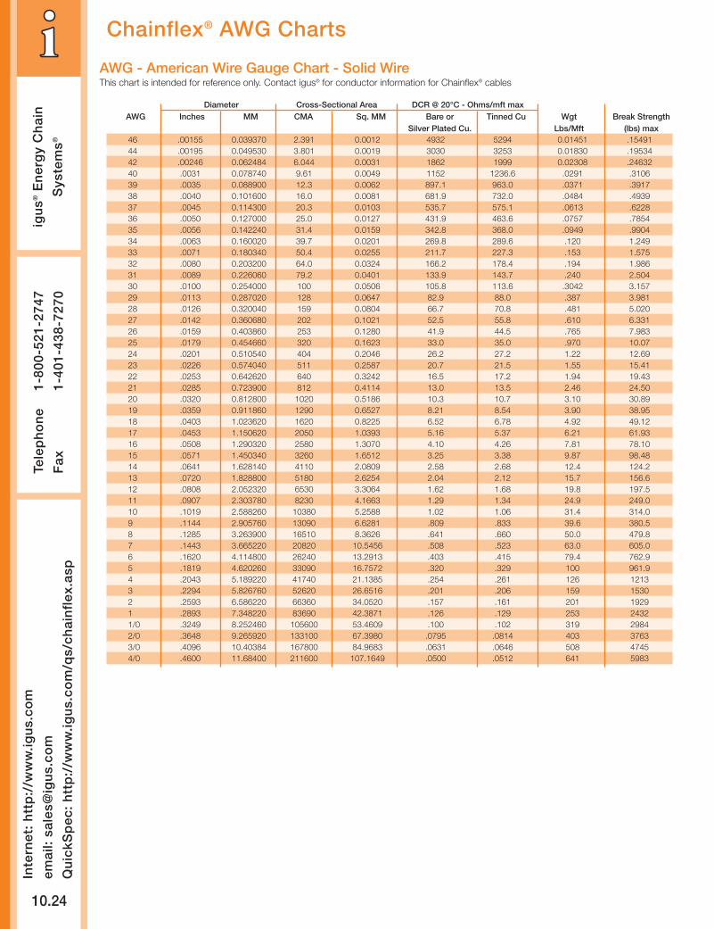
Chainflex® AWG Charts
Diameter Cross-Sectional Area DCR @ 20°C - Ohms/mft maxAWG Inches MM CMA Sq. MM Bare or Tinned Cu Wgt Break Strength
Silver Plated Cu. Lbs/Mft (lbs) max46 .00155 0.039370 2.391 0.0012 4932 5294 0.01451 .1549144 .00195 0.049530 3.801 0.0019 3030 3253 0.01830 .1953442 .00246 0.062484 6.044 0.0031 1862 1999 0.02308 .2463240 .0031 0.078740 9.61 0.0049 1152 1236.6 .0291 .310639 .0035 0.088900 12.3 0.0062 897.1 963.0 .0371 .391738 .0040 0.101600 16.0 0.0081 681.9 732.0 .0484 .493937 .0045 0.114300 20.3 0.0103 535.7 575.1 .0613 .622836 .0050 0.127000 25.0 0.0127 431.9 463.6 .0757 .785435 .0056 0.142240 31.4 0.0159 342.8 368.0 .0949 .990434 .0063 0.160020 39.7 0.0201 269.8 289.6 .120 1.24933 .0071 0.180340 50.4 0.0255 211.7 227.3 .153 1.57532 .0080 0.203200 64.0 0.0324 166.2 178.4 .194 1.98631 .0089 0.226060 79.2 0.0401 133.9 143.7 .240 2.50430 .0100 0.254000 100 0.0506 105.8 113.6 .3042 3.15729 .0113 0.287020 128 0.0647 82.9 88.0 .387 3.98128 .0126 0.320040 159 0.0804 66.7 70.8 .481 5.02027 .0142 0.360680 202 0.1021 52.5 55.8 .610 6.33126 .0159 0.403860 253 0.1280 41.9 44.5 .765 7.98325 .0179 0.454660 320 0.1623 33.0 35.0 .970 10.0724 .0201 0.510540 404 0.2046 26.2 27.2 1.22 12.6923 .0226 0.574040 511 0.2587 20.7 21.5 1.55 15.4122 .0253 0.642620 640 0.3242 16.5 17.2 1.94 19.4321 .0285 0.723900 812 0.4114 13.0 13.5 2.46 24.5020 .0320 0.812800 1020 0.5186 10.3 10.7 3.10 30.8919 .0359 0.911860 1290 0.6527 8.21 8.54 3.90 38.9518 .0403 1.023620 1620 0.8225 6.52 6.78 4.92 49.1217 .0453 1.150620 2050 1.0393 5.16 5.37 6.21 61.9316 .0508 1.290320 2580 1.3070 4.10 4.26 7.81 78.1015 .0571 1.450340 3260 1.6512 3.25 3.38 9.87 98.4814 .0641 1.628140 4110 2.0809 2.58 2.68 12.4 124.213 .0720 1.828800 5180 2.6254 2.04 2.12 15.7 156.612 .0808 2.052320 6530 3.3064 1.62 1.68 19.8 197.511 .0907 2.303780 8230 4.1663 1.29 1.34 24.9 249.010 .1019 2.588260 10380 5.2588 1.02 1.06 31.4 314.09 .1144 2.905760 13090 6.6281 .809 .833 39.6 380.58 .1285 3.263900 16510 8.3626 .641 .660 50.0 479.87 .1443 3.665220 20820 10.5456 .508 .523 63.0 605.06 .1620 4.114800 26240 13.2913 .403 .415 79.4 762.95 .1819 4.620260 33090 16.7572 .320 .329 100 961.94 .2043 5.189220 41740 21.1385 .254 .261 126 12133 .2294 5.826760 52620 26.6516 .201 .206 159 15302 .2593 6.586220 66360 34.0520 .157 .161 201 19291 .2893 7.348220 83690 42.3871 .126 .129 253 24321/0 .3249 8.252460 105600 53.4609 .100 .102 319 29842/0 .3648 9.265920 133100 67.3980 .0795 .0814 403 37633/0 .4096 10.40384 167800 84.9683 .0631 .0646 508 47454/0 .4600 11.68400 211600 107.1649 .0500 .0512 641 5983
AWG - American Wire Gauge Chart - Solid WireThis chart is intended for reference only. Contact igus® for conductor information for Chainflex® cables
PD
F:
ww
w.ig
us.
com
/pd
f/ch
ain
flex
.asp
Sp
ecs/
CA
D/R
FQ
: w
ww
.igu
s.co
m/c
hai
nfl
ex.a
sp
Ro
HS
info
: w
ww
.igu
s.co
m/R
oH
S.a
sp
igu
s®E
ner
gy
Ch
ain
Sys
tem
s®
Tele
ph
on
e1-
800-
521-
2747
Fax
1-
401-
438-
7270
10.25
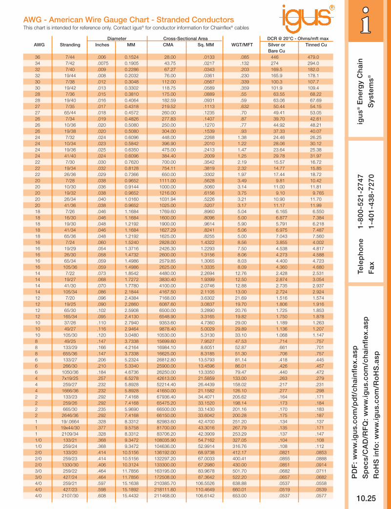
Diameter Cross-Sectional Area DCR @ 20°C - Ohms/mft maxAWG Stranding Inches MM CMA Sq. MM WGT/MFT Silver or Tinned Cu
Bare Cu36 7/44 .006 0.1524 28.00 .0133 .085 446 479.034 7/42 .0075 0.1905 43.75 .0217 .132 274 294.032 7/40 .009 0.2286 67.27 .0343 .203 169.5 182.032 19/44 .008 0.2032 76.00 .0361 .230 165.9 178.130 7/38 .012 0.3048 112.00 .0567 .339 100.3 107.730 19/42 .013 0.3302 118.75 .0589 .359 101.9 109.428 7/36 .015 0.3810 175.00 .0889 .55 63.55 68.2228 19/40 .016 0.4064 182.59 .0931 .59 63.06 67.6927 7/35 .017 0.4318 219.52 .1113 .632 50.44 54.1527 65/44 .018 0.4572 260.00 .1235 .70 49.41 53.0526 7/34 .019 0.4826 277.83 .1407 .87 39.70 42.6126 10/36 .020 0.5080 250.00 .1270 .77 44.92 48.2126 19/38 .020 0.5080 304.00 .1539 .93 37.33 40.0724 7/32 .024 0.6096 448.00 .2268 1.38 24.46 26.2524 10/34 .023 0.5842 396.90 .2010 1.22 28.06 30.1224 19/36 .025 0.6350 475.00 .2413 1.47 23.64 25.3824 41/40 .024 0.6096 384.40 .2009 1.25 29.78 31.9722 7/30 .030 0.7620 700.00 .3542 2.19 15.57 16.7222 19/34 .032 0.8128 754.11 .3819 2.32 14.77 15.8522 26/36 .029 0.7366 650.00 .3302 1.97 17.44 18.7220 7/28 .038 0.9652 1111.00 .5628 3.49 9.81 10.4220 10/30 .036 0.9144 1000.00 .5060 3.14 11.00 11.8120 19/32 .038 0.9652 1216.00 .6156 3.75 9.10 9.76520 26/34 .040 1.0160 1031.94 .5226 3.21 10.90 11.7020 41/36 .038 0.9652 1025.00 .5207 3.17 11.17 11.9918 7/26 .046 1.1684 1769.60 .8960 5.04 6.165 6.55018 16/30 .046 1.1684 1600.00 .8096 5.00 6.877 7.38418 19/30 .048 1.2192 1900.00 .9614 5.90 5.791 6.21818 41/34 .046 1.1684 1627.29 .8241 5.06 6.975 7.48718 65/36 .048 1.2192 1625.00 .8255 5.00 7.043 7.56016 7/24 .060 1.5240 2828.00 1.4322 8.56 3.855 4.00216 19/29 .054 1.3716 2426.30 1.2293 7.50 4.538 4.81716 26/30 .058 1.4732 2600.00 1.3156 8.06 4.273 4.58816 65/34 .059 1.4986 2579.85 1.3065 8.03 4.400 4.72316 105/36 .059 1.4986 2625.00 1.3335 8.09 4.360 4.68014 7/22 .073 1.8542 4480.00 2.2694 12.76 2.428 2.53114 19/27 .068 1.7272 3830.40 1.9399 12.50 2.874 3.05414 41/30 .070 1.7780 4100.00 2.0746 12.88 2.735 2.93714 105/34 .086 2.1844 4167.50 2.1105 13.00 2.724 2.92412 7/20 .096 2.4384 7168.00 3.6302 21.69 1.516 1.57412 19/25 .090 2.2860 6087.60 3.0837 19.70 1.806 1.91612 65/30 .102 2.5908 6500.00 3.2890 20.76 1.725 1.85312 165/34 .095 2.4130 6548.90 3.3165 19.82 1.750 1.87810 37/26 .110 2.7940 9353.60 4.7360 29.00 1.189 1.26310 49/27 .116 2.9464 9878.40 5.0029 29.89 1.136 1.20710 105/30 .120 3.0480 10530.00 5.3130 33.10 1.068 1.1478 49/25 .147 3.7338 15699.60 7.9527 47.53 .714 .7578 133/29 .166 4.2164 16984.10 8.6051 52.87 .661 .7018 655/36 .147 3.7338 16625.00 8.3185 51.30 .706 .7576 133/27 .206 5.2324 26812.80 13.5793 81.14 .418 .4456 266/30 .210 5.3340 25900.00 13.4596 86.01 .426 .4576 1050/36 .184 4.6736 26250.00 13.3350 79.47 .440 .4724 7x19/25 .257 6.5278 42613.00 21.5859 133.00 .263 .2794 259/27 .232 5.8928 52214.40 26.4439 158.02 .217 .2314 1666/36 .232 5.8928 41650.00 21.1582 126.10 .277 .2982 133/23 .292 7.4168 67936.40 34.4071 205.62 .164 .1712 259/26 .292 7.4168 65475.20 33.1520 198.14 .173 .1842 665/30 .235 5.9690 66500.00 33.1430 201.16 .170 .1832 2646/36 .292 7.4168 66150.00 33.6042 200.28 .175 .1871 19/.0664 .328 8.3312 82983.60 42.4700 251.20 .134 .1371 19x44/30 .377 9.5758 81700.00 43.3016 267.79 .135 .1711 2109/34 .328 8.3312 83706.20 42.3909 253.29 .137 .1471/0 133/21 .368 9.3472 108035.90 54.7162 327.05 .104 .1081/0 259/24 .368 9.3472 104636.00 52.9914 316.76 .108 .1122/0 133/20 .414 10.5156 136192.00 68.9738 412.17 .0821 .08532/0 259/23 .414 10.5156 132297.20 67.0033 400.41 .0855 .08882/0 1330/30 .406 10.3124 133300.00 67.2980 430.00 .0851 .09143/0 259/22 .464 11.7856 163195.00 83.9678 501.70 .0682 .07113/0 427/24 .464 11.7856 172508.00 87.3642 522.20 .0657 .06824/0 259/21 .597 15.1638 210385.70 106.5526 638.88 .0537 .05584/0 427/23 .598 15.1892 218111.60 110.4649 660.01 .0519 .05394/0 2107/30 .608 15.4432 211468.00 106.6142 653.00 .0537 .0577
AWG - American Wire Gauge Chart - Stranded ConductorsThis chart is intended for reference only. Contact igus® for conductor information for Chainflex® cables
Inte
rnet
: h
ttp
://w
ww
.igu
s.co
m
emai
l: sa
les@
igu
s.co
m
Qu
ickS
pec
: h
ttp
://w
ww
.igu
s.co
m/q
s/ch
ain
flex
.asp
igu
s®E
ner
gy
Ch
ain
Sys
tem
s®
10.26
Tele
ph
on
e1-
800-
521-
2747
Fax
1-
401-
438-
7270
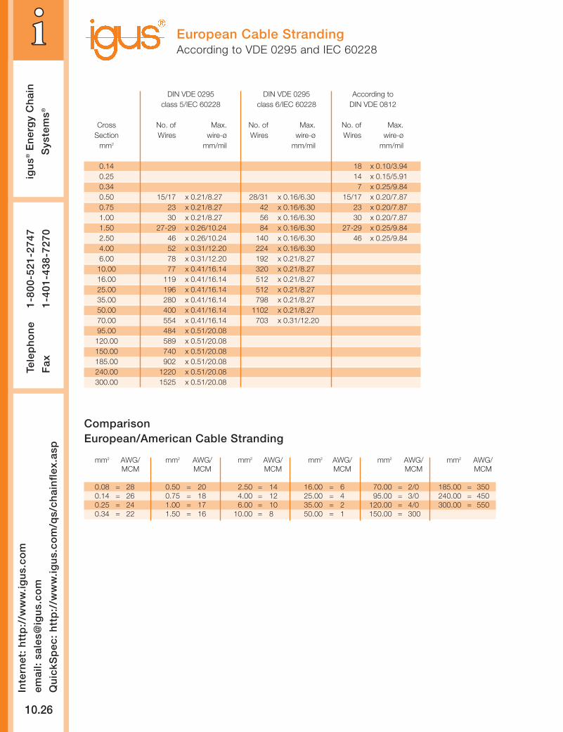
European Cable StrandingAccording to VDE 0295 and IEC 60228
ComparisonEuropean/American Cable Stranding
DIN VDE 0295 DIN VDE 0295 According toclass 5/IEC 60228 class 6/IEC 60228 DIN VDE 0812
Cross No. of Max. No. of Max. No. of Max.Section Wires wire-ø Wires wire-ø Wires wire-ø
mm2 mm/mil mm/mil mm/mil
0.14 18 x 0.10/3.940.25 14 x 0.15/5.910.34 7 x 0.25/9.840.50 15/17 x 0.21/8.27 28/31 x 0.16/6.30 15/17 x 0.20/7.870.75 23 x 0.21/8.27 42 x 0.16/6.30 23 x 0.20/7.871.00 30 x 0.21/8.27 56 x 0.16/6.30 30 x 0.20/7.871.50 27-29 x 0.26/10.24 84 x 0.16/6.30 27-29 x 0.25/9.842.50 46 x 0.26/10.24 140 x 0.16/6.30 46 x 0.25/9.844.00 52 x 0.31/12.20 224 x 0.16/6.306.00 78 x 0.31/12.20 192 x 0.21/8.2710.00 77 x 0.41/16.14 320 x 0.21/8.2716.00 119 x 0.41/16.14 512 x 0.21/8.2725.00 196 x 0.41/16.14 512 x 0.21/8.2735.00 280 x 0.41/16.14 798 x 0.21/8.2750.00 400 x 0.41/16.14 1102 x 0.21/8.2770.00 554 x 0.41/16.14 703 x 0.31/12.2095.00 484 x 0.51/20.08120.00 589 x 0.51/20.08150.00 740 x 0.51/20.08185.00 902 x 0.51/20.08240.00 1220 x 0.51/20.08300.00 1525 x 0.51/20.08
mm2 AWG/ mm2 AWG/ mm2 AWG/ mm2 AWG/ mm2 AWG/ mm2 AWG/MCM MCM MCM MCM MCM MCM
0.08 = 28 0.50 = 20 2.50 = 14 16.00 = 6 70.00 = 2/0 185.00 = 3500.14 = 26 0.75 = 18 4.00 = 12 25.00 = 4 95.00 = 3/0 240.00 = 4500.25 = 24 1.00 = 17 6.00 = 10 35.00 = 2 120.00 = 4/0 300.00 = 5500.34 = 22 1.50 = 16 10.00 = 8 50.00 = 1 150.00 = 300
PD
F:
ww
w.ig
us.
com
/pd
f/ch
ain
flex
.asp
Sp
ecs/
CA
D/R
FQ
: w
ww
.igu
s.co
m/c
hai
nfl
ex.a
sp
Ro
HS
info
: w
ww
.igu
s.co
m/R
oH
S.a
sp
igu
s®E
ner
gy
Ch
ain
Sys
tem
s®
Tele
ph
on
e1-
800-
521-
2747
Fax
1-
401-
438-
7270
10.27
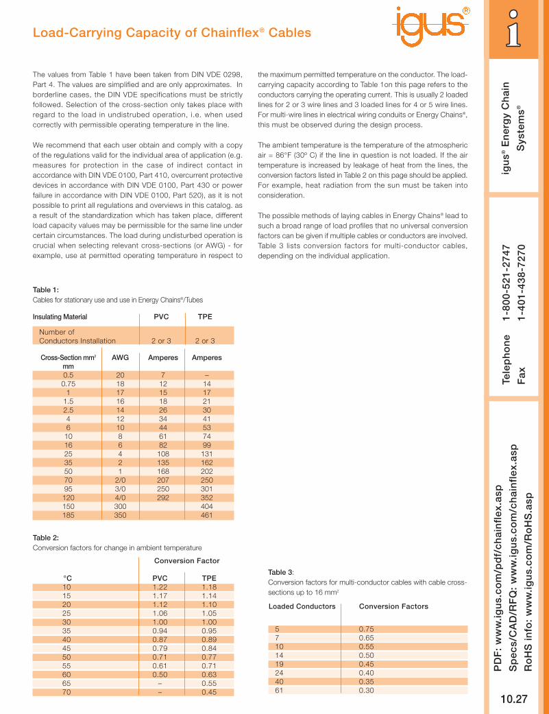
Load-Carrying Capacity of Chainflex® Cables
The values from Table 1 have been taken from DIN VDE 0298,Part 4. The values are simplified and are only approximates. Inborderline cases, the DIN VDE specifications must be strictlyfollowed. Selection of the cross-section only takes place withregard to the load in undistrubed operation, i.e. when usedcorrectly with permissible operating temperature in the line.
We recommend that each user obtain and comply with a copyof the regulations valid for the individual area of application (e.g.measures for protection in the case of indirect contact inaccordance with DIN VDE 0100, Part 410, overcurrent protectivedevices in accordance with DIN VDE 0100, Part 430 or powerfailure in accordance with DIN VDE 0100, Part 520), as it is notpossible to print all regulations and overviews in this catalog. asa result of the standardization which has taken place, differentload capacity values may be permissible for the same line undercertain circumstances. The load during undisturbed operation iscrucial when selecting relevant cross-sections (or AWG) - forexample, use at permitted operating temperature in respect to
the maximum permitted temperature on the conductor. The load-carrying capacity according to Table 1on this page refers to theconductors carrying the operating current. This is usually 2 loadedlines for 2 or 3 wire lines and 3 loaded lines for 4 or 5 wire lines.For multi-wire lines in electrical wiring conduits or Energy Chains®,this must be observed during the design process.
The ambient temperature is the temperature of the atmosphericair = 86°F (30º C) if the line in question is not loaded. If the airtemperature is increased by leakage of heat from the lines, theconversion factors listed in Table 2 on this page should be applied.For example, heat radiation from the sun must be taken intoconsideration.
The possible methods of laying cables in Energy Chains® lead tosuch a broad range of load profiles that no universal conversionfactors can be given if multiple cables or conductors are involved.Table 3 lists conversion factors for multi-conductor cables,depending on the individual application.
Table 1:Cables for stationary use and use in Energy Chains®/Tubes
Insulating Material PVC TPE
Number ofConductors Installation 2 or 3 2 or 3
Cross-Section mm2 AWG Amperes Amperesmm0.5 20 7 –0.75 18 12 14
1 17 15 171.5 16 18 212.5 14 26 304 12 34 416 10 44 5310 8 61 7416 6 82 9925 4 108 13135 2 135 16250 1 168 20270 2/0 207 25095 3/0 250 301120 4/0 292 352150 300 404185 350 461
Conversion Factor
°C PVC TPE10 1.22 1.1815 1.17 1.1420 1.12 1.1025 1.06 1.0530 1.00 1.0035 0.94 0.9540 0.87 0.8945 0.79 0.8450 0.71 0.7755 0.61 0.7160 0.50 0.6365 – 0.5570 – 0.45
Table 2:Conversion factors for change in ambient temperature
Table 3: Conversion factors for multi-conductor cables with cable cross-sections up to 16 mm2
Loaded Conductors Conversion Factors
5 0.757 0.6510 0.5514 0.5019 0.4524 0.4040 0.3561 0.30
10.28
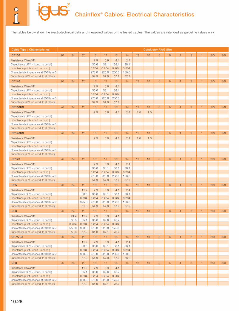
The tables below show the electrotechnical data and measured values of the tested cables. The values are intended as guideline values only.
Chainflex® Cables: Electrical Characteristics
Cable Type / Characteristics Conductor AWG Size
CF130 26 24 20 18 17 16 14 12 10 8 6 4 2 1 2/0 3/0
Resistance Ohms/Mft 7.9 5.9 4.1 2.4Capacitance pF/ft - (cond. to cond.) 36.6 38.1 38.1 38.1Inductance µH/ft- (cond. to cond.) 0.204 0.204 0.204 0.204Characteristic impedance at 800Hz in Ω 275.0 225.0 200.0 150.0Capacitance pF/ft - (1 cond. to all others) 54.9 57.9 57.9 57.9
CF140 26 24 20 18 17 16 14 12 10 8 6 4 2 1 2/0 3/0
Resistance Ohms/Mft 7.9 5.9 4.1Capacitance pF/ft - (cond. to cond.) 36.6 38.1 38.1Inductance µH/ft- (cond. to cond.) 0.204 0.204 0.204Characteristic impedance at 800Hz in Ω 275.0 225.0 200.0Capacitance pF/ft - (1 cond. to all others) 54.9 57.9 57.9
CF130US 26 24 20 18 17 16 14 12 10 8 6 4 2 1 2/0 3/0
Resistance Ohms/Mft 7.9 5.9 4.1 2.4 1.8 1.0Capacitance pF/ft - (cond. to cond.)Inductance µH/ft- (cond. to cond.)Characteristic impedance at 800Hz in ΩCapacitance pF/ft - (1 cond. to all others)
CF140US 26 24 20 18 17 16 14 12 10 8 6 4 2 1 2/0 3/0
Resistance Ohms/Mft 7.9 5.9 4.1 2.4 1.8 1.0Capacitance pF/ft - (cond. to cond.)Inductance µH/ft- (cond. to cond.)Characteristic impedance at 800Hz in ΩCapacitance pF/ft - (1 cond. to all others)
CF170 26 24 20 18 17 16 14 12 10 8 6 4 2 1 2/0 3/0
Resistance Ohms/Mft 7.9 5.9 4.1 2.4Capacitance pF/ft - (cond. to cond.) 36.6 38.1 38.1 38.1Inductance µH/ft- (cond. to cond.) 0.204 0.204 0.204 0.204Characteristic impedance at 800Hz in Ω 275.0 225.0 200.0 150.0Capacitance pF/ft - (1 cond. to all others) 54.9 57.9 57.9 57.9
CF5 26 24 20 18 17 16 14 12 10 8 6 4 2 1 2/0 3/0
Resistance Ohms/Mft 11.9 7.9 5.9 4.1 2.4Capacitance pF/ft - (cond. to cond.) 30.5 36.6 38.1 38.1 38.1Inductance µH/ft- (cond. to cond.) 0.204 0.204 0.204 0.204 0.204Characteristic impedance at 800Hz in Ω 375.0 275.0 225.0 200.0 150.0Capacitance pF/ft - (1 cond. to all others) 51.8 54.9 57.9 57.9 57.9
CF6 26 24 20 18 17 16 14 12 10 8 6 4 2 1 2/0 3/0
Resistance Ohms/Mft 24.4 11.9 7.9 5.9 4.1Capacitance pF/ft - (cond. to cond.) 30.5 35.1 36.6 39.6 45.7Inductance µH/ft- (cond. to cond.) 0.204 0.204 0.204 0.204 0.204Characteristic impedance at 800Hz in Ω 550.0 350.0 275.0 225.0 175.0Capacitance pF/ft - (1 cond. to all others) 50.3 57.9 61.0 67.1 76.2
CF7/7-D 26 24 20 18 17 16 14 12 10 8 6 4 2 1 2/0 3/0
Resistance Ohms/Mft 11.9 7.9 5.9 4.1 2.4Capacitance pF/ft - (cond. to cond.) 30.5 36.6 38.1 38.1 38.1Inductance µH/ft- (cond. to cond.) 0.204 0.204 0.204 0.204 0.204Characteristic impedance at 800Hz in Ω 350.0 275.0 225.0 200.0 150.0Capacitance pF/ft - (1 cond. to all others) 57.9 54.9 57.9 57.9 76.2
CF8 26 24 20 18 17 16 14 12 10 8 6 4 2 1 2/0 3/0
Resistance Ohms/Mft 11.9 7.9 5.9 4.1Capacitance pF/ft - (cond. to cond.) 35.1 36.6 39.6 45.7Inductance µH/ft- (cond. to cond.) 0.204 0.204 0.204 0.204Characteristic impedance at 800Hz in Ω 350.0 275.0 225.0 175.0Capacitance pF/ft - (1 cond. to all others) 57.9 61.0 67.1 76.2

10.29
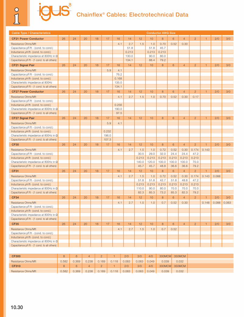
Chainflex® Cables: Electrotechnical Data
Cable Type / Characteristics Conductor AWG Size
CF2 26 24 20 18 17 16 14 12 10 8 6 4 2 1 2/0 3/0
Resistance Ohms/Mft 42.7 24.4 11.9 7.9 5.9 4.1Capacitance pF/ft - (cond. to cond.) 27.4 24.4 33.5 36.6 39.6 45.7Inductance µH/ft- (cond. to cond.) 0.204 0.204 0.204 0.204 0.204 0.204Characteristic impedance at 800Hz in Ω 750.0 550.0 350.0 275.0 225.0 175.0Capacitance pF/ft - (1 cond. to all others) 44.2 50.3 56.4 59.4 64.0 76.2
CF9 26 24 20 18 17 16 14 12 10 8 6 4 2 1 2/0 3/0
Resistance Ohms/Mft 7.9 5.9 4.1 2.4Capacitance pF/ft - (cond. to cond.) 30.5 33.5 33.5 36.6Inductance µH/ft- (cond. to cond.) 0.189 0.189 0.189 0.189Characteristic impedance at 800Hz in Ω 300.0 250.0 200.0 150.0Capacitance pF/ft - (1 cond. to all others) 51.8 51.8 51.8 57.9
CF10 26 24 20 18 17 16 14 12 10 8 6 4 2 1 2/0 3/0
Resistance Ohms/Mft 42.7 24.4Capacitance pF/ft - (cond. to cond.) 27.4 30.5Inductance µH/ft- (cond. to cond.) 0.192 0.192Characteristic impedance at 800Hz in Ω 750.0 525.0Capacitance pF/ft - (1 cond. to all others) 42.7 48.8
CF240 26 24 20 18 17 16 14 12 10 8 6 4 2 1 2/0 3/0
Resistance Ohms/Mft 24.4Capacitance pF/ft - (cond. to cond.) 36.6Inductance µH/ft- (cond. to cond.) 0.189Characteristic impedance at 800Hz in Ω 490.0Capacitance pF/ft - (1 cond. to all others) 58.5
CF211 26 24 20 18 17 16 14 12 10 8 6 4 2 1 2/0 3/0
Resistance Ohms/Mft 24.4 12.0Capacitance pF/ft - (cond. to cond.) 33.5 43.6Inductance µH/ft- (cond. to cond.) 0.183 0.162Characteristic impedance at 800Hz in Ω 530.0 330.0Capacitance pF/ft - (1 cond. to all others) 19.8
CF11/11-D 26 24 20 18 17 16 14 12 10 8 6 4 2 1 2/0 3/0
Resistance Ohms/Mft 24.4 7.9Capacitance pF/ft - (cond. to cond.) 39.6 36.6Inductance µH/ft- (cond. to cond.) 0.190 0.204Characteristic impedance at 800Hz in Ω 480.0 275.0Characteristic impedance at 100 Mhz in Ω 70.0 75.0
CF11-LC 26 24 20 18 17 16 14 12 10 8 6 4 2 1 2/0 3/0
Resistance Ohms/Mft 11.9Capacitance pF/ft - (cond. to cond.) 10.7Inductance µH/ft- (cond. to cond.) 0.207Characteristic impedance at 800Hz in Ω 650.0Characteristic impedance at 100 Mhz in Ω 120.0
CF12 26 24 20 18 17 16 14 12 10 8 6 4 2 1 2/0 3/0
Resistance Ohms/Mft 24.4 11.9Capacitance pF/ft - (cond. to cond.) 54.9 61.0Inductance µH/ft- (cond. to cond.) 0.189 0.158Characteristic impedance at 800Hz in Ω 420.0 280.0Characteristic impedance at 100 Mhz in Ω 60.0 50.0
CF14 CAT 5 26 24 20 18 17 16 14 12 10 8 6 4 2 1 2/0 3/0
Resistance Ohms/Mft 27.1Capacitance pF/ft - (cond. to cond.) 16.5Inductance µH/ft- (cond. to cond.) 0.189Characteristic impedance at 100 Mhz in Ω 108.0
10.30
Chainflex® Cables: Electrotechnical Data
Cable Type / Characteristics Conductor AWG Size
CF21 Power Conductor 26 24 20 18 17 16 14 12 10 8 6 4 2 1 2/0 3/0
Resistance Ohms/Mft 4.1 2.7 1.5 1.0 0.70 0.52 0.30Capacitance pF/ft - (cond. to cond.) 51.8 51.8 45.7Inductance µH/ft- (cond. to cond.) 0.213 0.213 0.213Characteristic impedance at 800Hz in Ω 130.0 90.0 80.0Capacitance pF/ft - (1 cond. to all others) 134.1 88.4 79.2
CF21 Signal Pair 26 24 20 18 17 16 14 12 10 8 6 4 2 1 2/0 3/0
Resistance Ohms/Mft 5.9 4.1Capacitance pF/ft - (cond. to cond.) 76.2Inductance µH/ft- (cond. to cond.) 0.168Characteristic impedance at 800Hz 135.0Capacitance pF/ft - (1 cond. to all others) 134.1
CF27 Power Conductor 26 24 20 18 17 16 14 12 10 8 6 4 2 1 2/0 3/0
Resistance Ohms/Mft 4.1 2.7 1.5 1.0 0.70 0.52 0.30 0.17Capacitance pF/ft - (cond. to cond.)Inductance µH/ft- (cond. to cond.) 0.256Characteristic impedance at 800Hz in Ω 190.0Capacitance pF/ft - (1 cond. to all others) 97.5
CF27 Signal Pair 26 24 20 18 17 16 14 12 10 8 6 4 2 1 2/0 3/0
Resistance Ohms/Mft 5.9 4.1Capacitance pF/ft - (cond. to cond.)Inductance µH/ft- (cond. to cond.) 0.232Characteristic impedance at 800Hz in Ω 196.0Capacitance pF/ft - (1 cond. to all others) 107.3
CF30 26 24 20 18 17 16 14 12 10 8 6 4 2 1 2/0 3/0
Resistance Ohms/Mft 4.1 2.7 1.5 1.0 0.72 0.52 0.30 0.174 0.143Capacitance pF/ft - (cond. to cond.) 30.5 29.0 32.0 24.4 24.4 47.2Inductance µH/ft- (cond. to cond.) 0.213 0.213 0.213 0.213 0.213 0.213Characteristic impedance at 800Hz in Ω 140.0 120.0 100.0 100.0 100.0 70.0Capacitance pF/ft - (1 cond. to all others) 45.7 45.7 48.8 36.6 36.6 79.2
CF31 26 24 20 18 17 16 14 12 10 8 6 4 2 1 2/0 3/0
Resistance Ohms/Mft 4.1 2.7 1.5 1.0 0.72 0.52 0.30 0.174 0.143 0.088Capacitance pF/ft - (cond. to cond.) 51.8 51.8 42.7 51.8 48.8 47.2Inductance µH/ft- (cond. to cond.) 0.213 0.213 0.213 0.213 0.213 0.213Characteristic impedance at 800Hz in Ω 110.0 90.0 80.0 70.0 70.0 70.0Capacitance pF/ft - (1 cond. to all others) 82.3 85.3 73.2 85.3 82.3 79.2
CF34 26 24 20 18 17 16 14 12 10 8 6 4 2 1 2/0 3/0
Resistance Ohms/Mft 4.1 2.7 1.5 1.0 0.7 0.52 0.30 0.148 0.088 0.063Capacitance pF/ft - (cond. to cond.)Inductance µH/ft- (cond. to cond.)Characteristic impedance at 800Hz in ΩCapacitance pF/ft - (1 cond. to all others)
CF35 26 24 20 18 17 16 14 12 10 8 6 4 2 1 2/0 3/0
Resistance Ohms/Mft 4.1 2.7 1.5 1.0 0.7 0.52Capacitance pF/ft - (cond. to cond.)Inductance µH/ft- (cond. to cond.)Characteristic impedance at 800Hz in ΩCapacitance pF/ft - (1 cond. to all others)
CF300 8 6 4 2 1 2/0 3/0 4/0 300MCM 350MCM
Resistance Ohms/Mft 0.582 0.369 0.238 0.169 0.118 0.083 0.063 0.049 0.039 0.032
CF310 8 6 4 2 1 2/0 3/0 4/0 300MCM 350MCM
Resistance Ohms/Mft 0.582 0.369 0.238 0.169 0.118 0.083 0.063 0.049 0.039 0.032

10.31
Chainflex® Cables: Electromagnetic Compatibility
The “Electromagnetic Compatability” of Chainflex® Cables
The subject of "electromagnetic compatibility (EMC)" is increasing inimportance. This is due in part, to the increase in electro-magneticinterference fields, both in the environment created by moderntelecommunications and the power systems used by localgovernments.
However, data transmission requirements are becoming more stringent.The signals are increasingly susceptible to interference and ambientelectromagnetic interference is diversifying.
The coupling between cables which, as is frequently the case withEnergy Chains®, are routed parallel over a certain distance may bespecific problematic.
A power cable exposed to interference acts as the generator of anelectromagnetic interference field which, in turn, acts on another cable(normally a signal cable) and causes conducted interference
We therefore introduced glass and polymer fiber optic cables a fewyears ago, which are capable of withstanding the mechanical stressesof use in Energy Chains®.
Chainflex cables using conventional copper conductors were testedfor their electromagnetic compatibility in an extensive, application-oriented testing program.
For example, an asynchronous motor was connected via an unshieldedpower cable (Chainflex® CF30) to a frequency converter. This frequencyconverter with pulse width modulation generates new spectral
components not present to date either in the primary power systemor in the secondary power system.
Chainflex® cables for digital signal transmission in an Energy Chain®
were guided parallel to this power cable. The Chainflex® CF 12 cable(the no interference cables), designed taking EMC aspects intoaccount, is particularly efficient. This cable features twisted pairconductors with individual copper shielding, along with an overallferrous shield. This ensures effective interference suppression overa wide frequency range.
Both capacitive and inductive coupling were tested. Under the testconditions selected, we were able to determine that, even if powerand signal cables contact each other over a long distance, it is possibleto achieve errorless data transmission if a shielded Chainflex® cableis used and this shield is grounded at both ends.
Tests were also carried out in accordance with applicable EMCcompatibility standards. These standards are the basis for determiningthe operational performance of electrical equipment repeatedly exposedto electrical interference. These standards were not introduced solelyfor cables. Specifically, tests were carried out using a "burst generator,"where rapid, transient interference is generated in pulse runs, mainlysimulating switching operations. Such transient phenomena areproduced, for example, by interrupting inductive loads or with relaycontact bounce. As with other tests, shielded Chainflex® cables provedto be highly efficient.
10.32
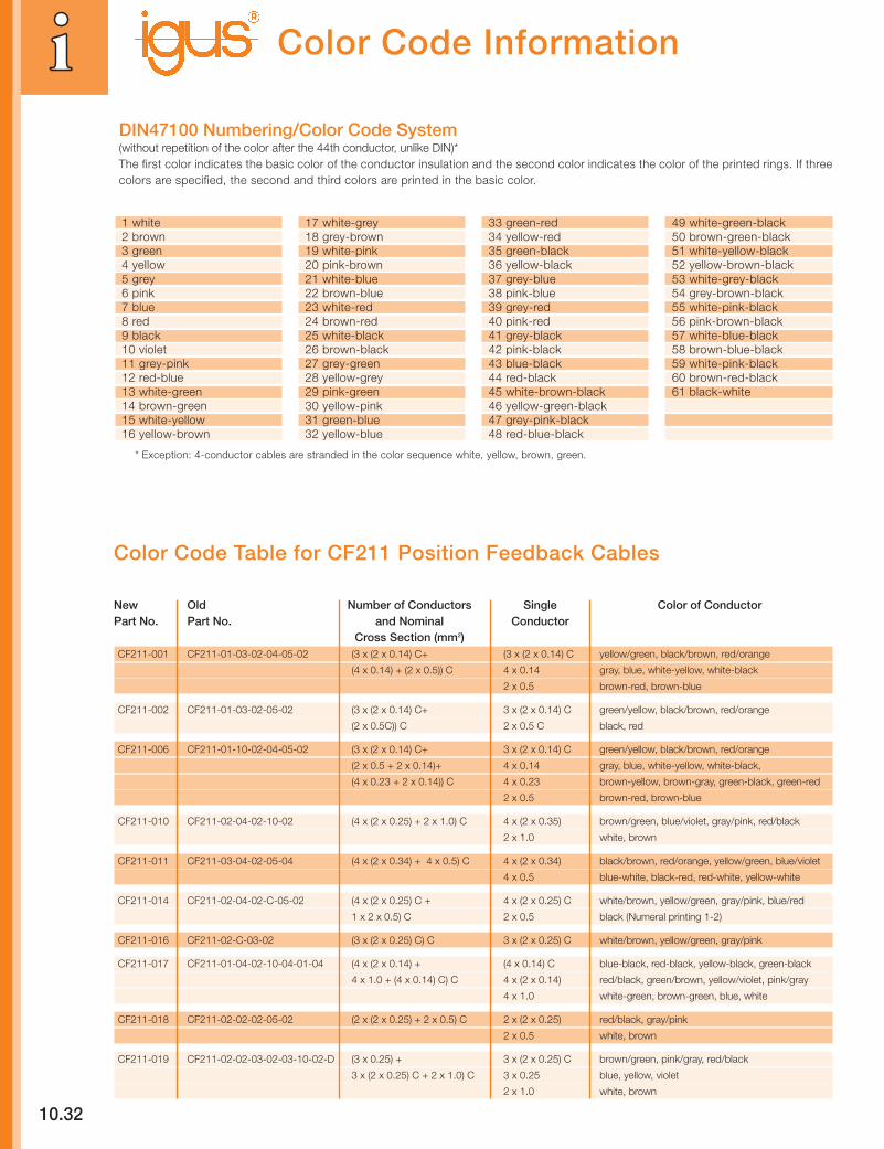
New Old Number of Conductors Single Color of ConductorPart No. Part No. and Nominal Conductor
Cross Section (mm2)CF211-001 CF211-01-03-02-04-05-02 (3 x (2 x 0.14) C+ (3 x (2 x 0.14) C yellow/green, black/brown, red/orange
(4 x 0.14) + (2 x 0.5)) C 4 x 0.14 gray, blue, white-yellow, white-black
2 x 0.5 brown-red, brown-blue
CF211-002 CF211-01-03-02-05-02 (3 x (2 x 0.14) C+ 3 x (2 x 0.14) C green/yellow, black/brown, red/orange
(2 x 0.5C)) C 2 x 0.5 C black, red
CF211-006 CF211-01-10-02-04-05-02 (3 x (2 x 0.14) C+ 3 x (2 x 0.14) C green/yellow, black/brown, red/orange
(2 x 0.5 + 2 x 0.14)+ 4 x 0.14 gray, blue, white-yellow, white-black,
(4 x 0.23 + 2 x 0.14)) C 4 x 0.23 brown-yellow, brown-gray, green-black, green-red
2 x 0.5 brown-red, brown-blue
CF211-010 CF211-02-04-02-10-02 (4 x (2 x 0.25) + 2 x 1.0) C 4 x (2 x 0.35) brown/green, blue/violet, gray/pink, red/black
2 x 1.0 white, brown
CF211-011 CF211-03-04-02-05-04 (4 x (2 x 0.34) + 4 x 0.5) C 4 x (2 x 0.34) black/brown, red/orange, yellow/green, blue/violet
4 x 0.5 blue-white, black-red, red-white, yellow-white
CF211-014 CF211-02-04-02-C-05-02 (4 x (2 x 0.25) C + 4 x (2 x 0.25) C white/brown, yellow/green, gray/pink, blue/red
1 x 2 x 0.5) C 2 x 0.5 black (Numeral printing 1-2)
CF211-016 CF211-02-C-03-02 (3 x (2 x 0.25) C) C 3 x (2 x 0.25) C white/brown, yellow/green, gray/pink
CF211-017 CF211-01-04-02-10-04-01-04 (4 x (2 x 0.14) + (4 x 0.14) C blue-black, red-black, yellow-black, green-black
4 x 1.0 + (4 x 0.14) C) C 4 x (2 x 0.14) red/black, green/brown, yellow/violet, pink/gray
4 x 1.0 white-green, brown-green, blue, white
CF211-018 CF211-02-02-02-05-02 (2 x (2 x 0.25) + 2 x 0.5) C 2 x (2 x 0.25) red/black, gray/pink
2 x 0.5 white, brown
CF211-019 CF211-02-02-03-02-03-10-02-D (3 x 0.25) + 3 x (2 x 0.25) C brown/green, pink/gray, red/black
3 x (2 x 0.25) C + 2 x 1.0) C 3 x 0.25 blue, yellow, violet
2 x 1.0 white, brown
Color Code Table for CF211 Position Feedback Cables
Color Code Information
1 white2 brown3 green4 yellow5 grey6 pink7 blue8 red9 black10 violet11 grey-pink12 red-blue13 white-green14 brown-green15 white-yellow16 yellow-brown
17 white-grey18 grey-brown19 white-pink20 pink-brown21 white-blue22 brown-blue23 white-red24 brown-red25 white-black26 brown-black27 grey-green28 yellow-grey29 pink-green30 yellow-pink31 green-blue32 yellow-blue
33 green-red34 yellow-red35 green-black36 yellow-black37 grey-blue38 pink-blue39 grey-red40 pink-red41 grey-black42 pink-black43 blue-black44 red-black45 white-brown-black46 yellow-green-black47 grey-pink-black48 red-blue-black
49 white-green-black50 brown-green-black51 white-yellow-black52 yellow-brown-black53 white-grey-black54 grey-brown-black55 white-pink-black56 pink-brown-black57 white-blue-black58 brown-blue-black59 white-pink-black60 brown-red-black61 black-white
DIN47100 Numbering/Color Code System(without repetition of the color after the 44th conductor, unlike DIN)*The first color indicates the basic color of the conductor insulation and the second color indicates the color of the printed rings. If threecolors are specified, the second and third colors are printed in the basic color.
* Exception: 4-conductor cables are stranded in the color sequence white, yellow, brown, green.
10.33
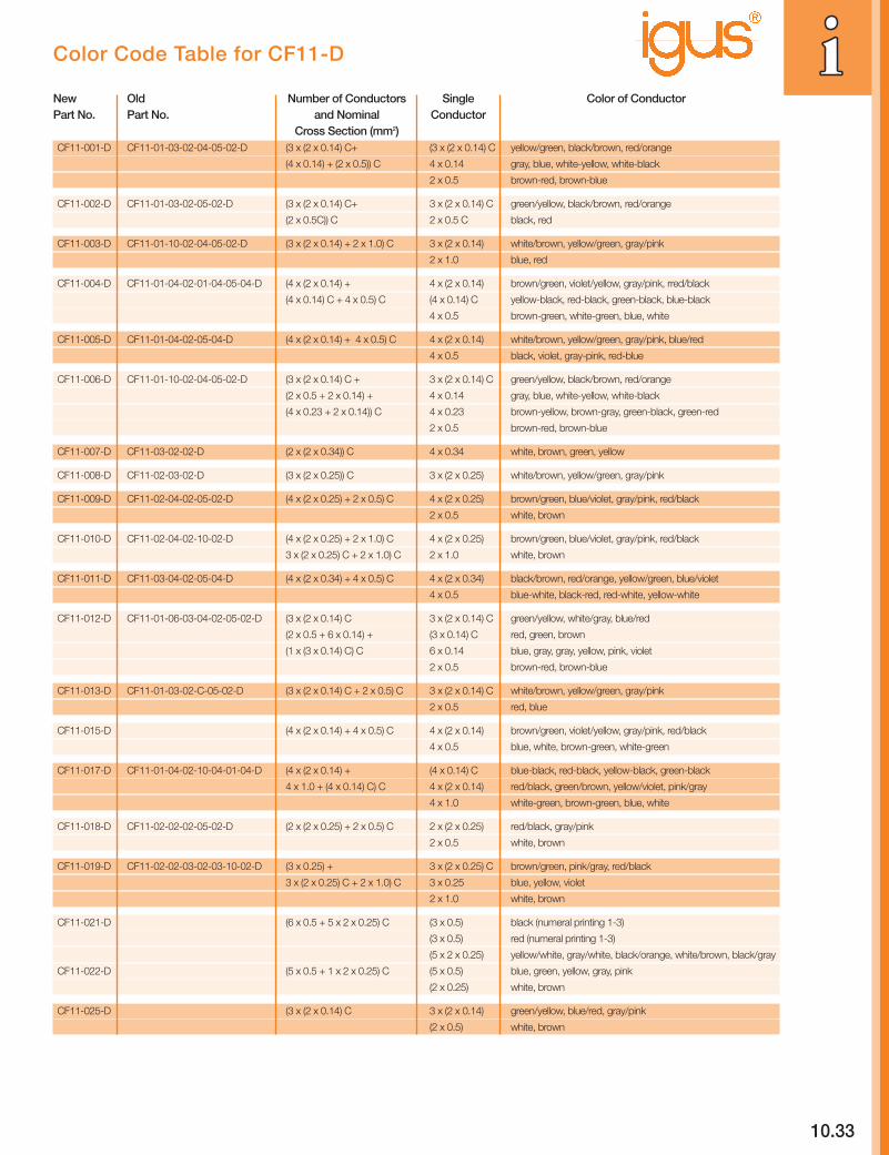
Color Code Table for CF11-D
New Old Number of Conductors Single Color of ConductorPart No. Part No. and Nominal Conductor
Cross Section (mm2)CF11-001-D CF11-01-03-02-04-05-02-D (3 x (2 x 0.14) C+ (3 x (2 x 0.14) C yellow/green, black/brown, red/orange
(4 x 0.14) + (2 x 0.5)) C 4 x 0.14 gray, blue, white-yellow, white-black
2 x 0.5 brown-red, brown-blue
CF11-002-D CF11-01-03-02-05-02-D (3 x (2 x 0.14) C+ 3 x (2 x 0.14) C green/yellow, black/brown, red/orange
(2 x 0.5C)) C 2 x 0.5 C black, red
CF11-003-D CF11-01-10-02-04-05-02-D (3 x (2 x 0.14) + 2 x 1.0) C 3 x (2 x 0.14) white/brown, yellow/green, gray/pink
2 x 1.0 blue, red
CF11-004-D CF11-01-04-02-01-04-05-04-D (4 x (2 x 0.14) + 4 x (2 x 0.14) brown/green, violet/yellow, gray/pink, rred/black
(4 x 0.14) C + 4 x 0.5) C (4 x 0.14) C yellow-black, red-black, green-black, blue-black
4 x 0.5 brown-green, white-green, blue, white
CF11-005-D CF11-01-04-02-05-04-D (4 x (2 x 0.14) + 4 x 0.5) C 4 x (2 x 0.14) white/brown, yellow/green, gray/pink, blue/red
4 x 0.5 black, violet, gray-pink, red-blue
CF11-006-D CF11-01-10-02-04-05-02-D (3 x (2 x 0.14) C + 3 x (2 x 0.14) C green/yellow, black/brown, red/orange
(2 x 0.5 + 2 x 0.14) + 4 x 0.14 gray, blue, white-yellow, white-black
(4 x 0.23 + 2 x 0.14)) C 4 x 0.23 brown-yellow, brown-gray, green-black, green-red
2 x 0.5 brown-red, brown-blue
CF11-007-D CF11-03-02-02-D (2 x (2 x 0.34)) C 4 x 0.34 white, brown, green, yellow
CF11-008-D CF11-02-03-02-D (3 x (2 x 0.25)) C 3 x (2 x 0.25) white/brown, yellow/green, gray/pink
CF11-009-D CF11-02-04-02-05-02-D (4 x (2 x 0.25) + 2 x 0.5) C 4 x (2 x 0.25) brown/green, blue/violet, gray/pink, red/black
2 x 0.5 white, brown
CF11-010-D CF11-02-04-02-10-02-D (4 x (2 x 0.25) + 2 x 1.0) C 4 x (2 x 0.25) brown/green, blue/violet, gray/pink, red/black
3 x (2 x 0.25) C + 2 x 1.0) C 2 x 1.0 white, brown
CF11-011-D CF11-03-04-02-05-04-D (4 x (2 x 0.34) + 4 x 0.5) C 4 x (2 x 0.34) black/brown, red/orange, yellow/green, blue/violet
4 x 0.5 blue-white, black-red, red-white, yellow-white
CF11-012-D CF11-01-06-03-04-02-05-02-D (3 x (2 x 0.14) C 3 x (2 x 0.14) C green/yellow, white/gray, blue/red
(2 x 0.5 + 6 x 0.14) + (3 x 0.14) C red, green, brown
(1 x (3 x 0.14) C) C 6 x 0.14 blue, gray, gray, yellow, pink, violet
2 x 0.5 brown-red, brown-blue
CF11-013-D CF11-01-03-02-C-05-02-D (3 x (2 x 0.14) C + 2 x 0.5) C 3 x (2 x 0.14) C white/brown, yellow/green, gray/pink
2 x 0.5 red, blue
CF11-015-D (4 x (2 x 0.14) + 4 x 0.5) C 4 x (2 x 0.14) brown/green, violet/yellow, gray/pink, red/black
4 x 0.5 blue, white, brown-green, white-green
CF11-017-D CF11-01-04-02-10-04-01-04-D (4 x (2 x 0.14) + (4 x 0.14) C blue-black, red-black, yellow-black, green-black
4 x 1.0 + (4 x 0.14) C) C 4 x (2 x 0.14) red/black, green/brown, yellow/violet, pink/gray
4 x 1.0 white-green, brown-green, blue, white
CF11-018-D CF11-02-02-02-05-02-D (2 x (2 x 0.25) + 2 x 0.5) C 2 x (2 x 0.25) red/black, gray/pink
2 x 0.5 white, brown
CF11-019-D CF11-02-02-03-02-03-10-02-D (3 x 0.25) + 3 x (2 x 0.25) C brown/green, pink/gray, red/black
3 x (2 x 0.25) C + 2 x 1.0) C 3 x 0.25 blue, yellow, violet
2 x 1.0 white, brown
CF11-021-D (6 x 0.5 + 5 x 2 x 0.25) C (3 x 0.5) black (numeral printing 1-3)
(3 x 0.5) red (numeral printing 1-3)
(5 x 2 x 0.25) yellow/white, gray/white, black/orange, white/brown, black/gray
CF11-022-D (5 x 0.5 + 1 x 2 x 0.25) C (5 x 0.5) blue, green, yellow, gray, pink
(2 x 0.25) white, brown
CF11-025-D (3 x (2 x 0.14) C 3 x (2 x 0.14) green/yellow, blue/red, gray/pink
(2 x 0.5) white, brown
10.3410.34
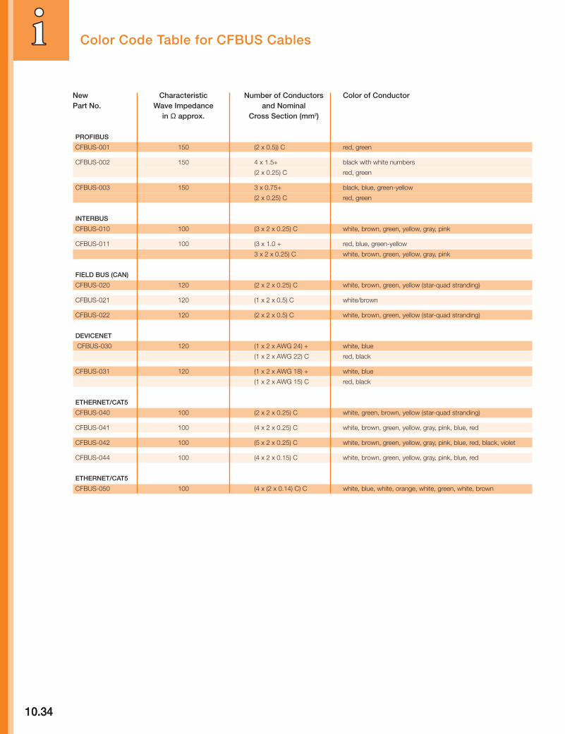
New Characteristic Number of Conductors Color of ConductorPart No. Wave Impedance and Nominal
in Ω approx. Cross Section (mm2)
PROFIBUS
CFBUS-001 150 (2 x 0.5)) C red, green
CFBUS-002 150 4 x 1.5+ black with white numbers
(2 x 0.25) C red, green
CFBUS-003 150 3 x 0.75+ black, blue, green-yellow
(2 x 0.25) C red, green
INTERBUS
CFBUS-010 100 (3 x 2 x 0.25) C white, brown, green, yellow, gray, pink
CFBUS-011 100 (3 x 1.0 + red, blue, green-yellow
3 x 2 x 0.25) C white, brown, green, yellow, gray, pink
FIELD BUS (CAN)
CFBUS-020 120 (2 x 2 x 0.25) C white, brown, green, yellow (star-quad stranding)
CFBUS-021 120 (1 x 2 x 0.5) C white/brown
CFBUS-022 120 (2 x 2 x 0.5) C white, brown, green, yellow (star-quad stranding)
DEVICENET
CFBUS-030 120 (1 x 2 x AWG 24) + white, blue
(1 x 2 x AWG 22) C red, black
CFBUS-031 120 (1 x 2 x AWG 18) + white, blue
(1 x 2 x AWG 15) C red, black
ETHERNET/CAT5
CFBUS-040 100 (2 x 2 x 0.25) C white, green, brown, yellow (star-quad stranding)
CFBUS-041 100 (4 x 2 x 0.25) C white, brown, green, yellow, gray, pink, blue, red
CFBUS-042 100 (5 x 2 x 0.25) C white, brown, green, yellow, gray, pink, blue, red, black, violet
CFBUS-044 100 (4 x 2 x 0.15) C white, brown, green, yellow, gray, pink, blue, red
ETHERNET/CAT5
CFBUS-050 100 (4 x (2 x 0.14) C) C white, blue, white, orange, white, green, white, brown
Color Code Table for CFBUS Cables

10.35
CF130, CF140 CF5, CF6, CF21, CF2, CF7, CF8, CF27 CF9, CF10, CF11, CF12, CF14Cable Type CF30, CF31, CF240 CF170, CF14US CFBUS, CF98, CF34, CF35, CFPE
CF211, CF130US, CF140US CFKoax1, CF300, CF310Inorganic chemicalsAqueous solutions, neutralWater + + + +Sodium chloride (10%) + + + +Glauber salt (10%) + + + +Aqueous solutions, alkalineSoda (10%) O + O +Aqueous solution, acidicSodium bisulfate(10%) O + O +Aqueous solutions, oxidizingHydrogen peroxide (10%) + + + +Potassium permanganate (2%) + + + +Inorganic acidsConcentrated hydrochloric acid – – – –Hydrochloric acid (10%) O O O +Concentrated sulfuric acid – – – –Sulfuric acid (10%) O O O +Concentrated nitric acid – – – –Nitric acid (10%) O O O +Inorganic basesConcentrated sodium hydroxide solution – – – OSodium hydroxide solution (10%) O O O +Concentrated potassium hydroxide solution – – – OPotassium hydroxide solution (10%) O O O +Concentrated ammonia O O O +Ammonia (10%) + + + +
Organic chemicalsOrganic acidsConcentrated acetic acid (glacial acetic acid) – – – OAcetic acid (10% in H20) O + O +Tartaric acid (10% in H20) O + + +Citric acid (10% in H20) O + + +KetonesAcetone – – – OMethyl ethyl ketone (MEK) – – – OAlcoholsEthanol (spirits) – O O +Isopropanol – O O +Diethylene glycol O O + +Aromatic hydrocarbonsToluene – – O –Xylene – – O –FuelsBenzine – O + +Diesel fuel – O + +Synthetic oilsLubricantsASTM Oil #2 O + + +Hydraulic oilMineral oil base – O + +Glycol base O O + +Synthetic ester base – O + +Vegetable oilsRape-seed oil O + + +Olive oil O + + +Soybean oil O + + +Cold cleaning agentCold cleaning agent – O + O
+ = no/few negative effects - = unstable, partial destruction of material0 = average interaction, short-term exposure permissible All information applies to room temperature
Chainflex® Cables: Chemical Resistance