maximizing lte performance through precoding with low ... · while lte can provide ... other rf...
TRANSCRIPT

I J C T A, 9(4), 2016, pp. 273-282© International Science Press
1 Research Scholar, Anna University, Chennai. Assistant Professor, Vel Tech High Tech Dr. Rangarajan Dr. Sakunthala EngineeringCollege, Chennai.
2 Professor, Department of ECE, Thiagarajar College of Engineering, Madurai.
Maximizing LTE Performance throughPrecoding with Low Complexity forMIMO OptimizationN. Duraichi1, and M. Suganthi2
ABSTRACT
In Multiple-input multiple-output (MIMO) technology has been successfully integrated in a series of well-establishedwireless communication standards. Linear precoding techniques can achieve near optimal capacity due to the specialchannel property in downlink massive MIMO systems, but involve high complexity since complicated matrixinversion of large size is required. A low-complexity linear precoding technique based on the Gauss-Seidel (GS)method. The proposed scheme can achieve the capacity and performance of the classical linear precoding schemesin an iterative way without complicated matrix inversion and can be reduce the overall complexity by the order ofmagnitude. The performance guarantee of the proposed GS-based precoding is analysed from the following threeaspects. Therefore, network operator’s new technologies such as LTE generate more throughput from existingbandwidth. While LTE can provide increased capacity using standard antenna techniques to widespread deploymentand optimization of MIMO (Multiple-Input Multiple-Output) antenna techniques can multiplicative effect on LTE’sdata throughput. MIMO techniques, in turn, present their own unique challenges, requiring a new approach tonetwork measurement and optimization.
Keywords: Multiple-input–multiple-output systems, linear precoding, Gauss-Seidel (GS) method, low complexity,spatial modulation (SM), spatial multiplexing (SMX), transmit precoding (TPC).
1. INTRODUCTION
MIMO technology has its roots in more widely deployed in the antenna techniques. MIMO builds onSingle-Input Multiple-Output known as receive diversity as well as Multiple-Input Single-Output, alsocalled transmit diversity. SIMO techniques for decades, while MISO is most advanced cellular networkstoday. Both of these techniques are boost signal-to-noise ratio in order to compensate signal degradation.As a radio frequency signal are passes from Tx to Rx and its gradually weakens, and interference fromother RF signals also reduces SNR. The RF signal frequently encounters objects hich will alter its pathsignal. Multiple-antenna systems are compensate for some of the loss of SNR due to multiple path conditionsare combining signals that have different fading characteristics, since the path from each antenna slightlydifferent. SIMO and MISO systems are achieve SNR gain by combining signals that take multiple paths forTx and Rx in a constructive manner each signal 3. Because different antennas receive and transmit thesame signal are achieve SNR gains even in line of sight situations. The boost in SNR can then be used toincrease the range of the connection by using a modulation scheme is 16QAM rather than QPSK. MIMOcan combination of SIMO and MISO techniques for resulting in even greater SNR gains boosting coverageand data rates. However, when SNR is high for additional throughput gains are minimal and there is littlebenefit from further boosting SNR. To achieve throughput gains where SNR is already very high. LTEoptimized MIMO technique called spatial multiplexing. In spatial multiplexing, each Tx sends a different

274 N. Duraichi, and M. Suganthi
data stream for multiple Rx. These data streams are reconstructed separately by the UE. It may seemcounterintuitive that two signals for same time and frequency within the same sector can result in increasedthroughput rather than interference. The spatial multiplexing are compared to conventional spectrum re-use, where signals are transmitted for same frequency in different cells. For spectrum re-use in the cellsmust be far enough apart that is, they must occupy different space and in order to avoid interference. Withspatial multiplexing, the signals, instead of occupying a completely different cell, different space-time inthe same cell. Good multipath conditions create the signal orthogonality a single cell into multiple cells forrespect to the amount of data that can be sent on a particular frequency band.
Multipath conditions, spatial multiplexing are depends on high SNR to produce large throughput gains.The spatial multiplexing is even though multiple data streams are transmitted, the total power of thetransmission remains same. Therefore spatial multiplexing are distributes to total SNR between these multipledata streams, each lower power level. The result is each data stream contains a lower SNR than would bepossible with single data stream. Because there are diminishing returns for additional SNR when SNR isalready high, each multiple data streams may be capable of transmitting nearly as much data as a singlestream. The increased data capacity results are sharing SNR between multiple data streams means that,while spatial multiplexing may be used to encode same data differently and boost SNR are recombineddata streams, it can also be used to completely different data through Tx. In LTE, each set of data sentthrough the antennas in a spatial multiplexing operation is known as layer. Under ideal conditions, eachlayer of a spatial multiplexing transmission will contain as a single-Tx LTE transmission. The result is thatspatial multiplexing can theoretically multiple throughput in the transmission rank. This multiplicativeeffect on throughput means that MIMO technology is essential for full benefits of LTE. With the 2�2 (2 Txand 2 Rx) antenna configuration expected to be deployed by effective use of MIMO nearly double throughputboth for individual users and for each cell as a whole.
The throughput gains are depend on three factors: maximizing rich scattering conditions within a cellconfiguring eNodeB to properly match MIMO settings to real-world conditions, and ensuring that UEs cantake full advantage are multipath conditions are present. Scanning receivers that can provide accurate real-world measurements of multipath conditions and potential throughput are essential for evaluating theperformance of all three of these factors. The measurements are using mobile operators can maximize thedata rates and reliability of LTE networks.
More recently, spatial modulation (SM) has been conceived for implicitly encoding information in theindex of the specific antenna activated for the transmission of the modulated symbols, offering a low-
Figure 1: Multiple Paths from eNodeB to UE in 2 2 MIMO

Maximizing LTE Performance through Precoding with Low Complexity for MIMO Optimization 275
complexity design alternative [2]. Its central benefits include the absence of inter antenna interference(IAI) and the fact that it only requires a subset (down to one) of radio-frequency (RF) chains compared withSMX. Accordingly, the inter antenna synchronization is also relaxed. The design of receiver algorithms forminimizing the bit error ratio (BER) of SM at low complexity. The work spans from matched filtering as alow complexity technique for detecting the antenna index used for SM [11] to the maximum likelihood(ML) [10] with a significantly reduced complexity compared with classic SMX ML detectors, includingcompressive sensing approaches [9] and performance analyses. Reduced-space sphere detection has alsobeen proposed for SM in [5] for further complexity reduction where a generalized SM transmission wasalso explored. In addition to receive processing, recent work has also proposed constellation shaping forSM. Specifically, the work on this topic has focused on three main directions: shaping and optimization ofthe spatial constellation, i.e., the legitimate sets of activated transmit antennas (TAs), modulation constellationshaping for the SM and space shift keying transmission, where the constellation of the modulated bits isoptimized, and joint spatial and modulation constellation shaping, in the form of optimizing the receivedconstellation.
2. MIMO USING SPATIAL MULTIPLEXING SYSTEM
MIMO technology are widely deployed antenna techniques. MIMO builds on Single-Input Multiple-Outputalso called receive diversity or Multiple-Input Single-Output also called transmit diversity. SIMO techniquesaround for decades. The MISO is advanced cellular networks today. Both of these techniques shown boostsignal-to-noise ratio compensate for signal degradation. A radio frequency (RF) signal passes from Tx toRx, it gradually interference from other RF signals also reduces SNR. The RF signal frequently encountersobjects which will alter its degrade signal. Multiple-antenna systems are compensate for loss of SNR dueto multipath conditions by combining signals for different fading characteristics of the path from eachantenna will be slightly different. SIMO and MISO systems are achieve SNR gain combining signals thattake multiple paths to the Tx and Rx in a constructive manner best piece of each signal. Because differentantennas receive or transmit the same signal for systems can achieve SNR gains are line sight situations.The boost in SNR can then be used to increase the range for boost data rates are using modulation schemesuch as 16QAM or 64QAM rather than QPSK.
During each symbol period, R bits are de-multiplexed into M different bit streams and modulatedindependently using constellation S. Note that the number of bits per sub stream is R/M so that R bits aretransmitted irrespective value M. The spatial multiplexer produces a symbol vector s
k at symbol period k
where1 sk = [sk, 1, sk, 2, . . ., sk, M]T For convenience we assume that EssksH
k = EsMIM where IM is the
M × M identity matrix. Notice that sk, and thus the constellation that the entries of sk are chosen from, arenormalized so that the total transmit power is EssHksk = Es irrespectively of M. Throughout, it is assumedthat M � Mr. The symbol vector sk is precoded by a Mt × M precoding matrix WM, p � W(M, Mt) where
Figure 2: A spatial multiplexing system with feedback

276 N. Duraichi, and M. Suganthi
WM,p is the pth entry in W(M, Mt), the ordered set of Mt ×M matrices constructed by combinations ofM columns in the identity matrix IMt. It is shown that |W(M, Mt)| = Mt M. Essentially W(M, Mt) is the setof size M subsets of Mt transmit antennas while M is the number of data streams. For example, forMt = 2,
1 0 1 01, 2 , , 2, 2
0 1 0 1w w
The parameters M and p are determined on feedback from the receiver. Thus as mentioned before thisframework includes antenna subset selection as a special case but is even more general. Assuming there areno symbol timing errors and frequency offsets for the Mr × 1 received signal vector after matched filteringand sampling can be written as
,k M p k ky HW S V
Where H is the channel matrix and vk is the noise vector. We assume the entries of H are i.i.d. accordingto CN (0, 1) and the entries of vk are i.i.d. according to CN (0, N0). We refer to HWM,p as the equivalentchannel. The channel is constant across frame of data but varies independently from frame to frame. Thesubsequent notation we assume that frame with a single symbol, thus we let k = 1 and suppress the ksubscripts.
At the receiver, y is multiplied by an M × M matrix and then each entry of the resulting vector isdetected independently. For a ZF linear decoder G = (HW
M,p) while for the MMSE linear decoder
11, , 0 ,
H H H HM p M p M M pG W H HW I W H
Where �0 = Es/MNo. The receivers are easily implemented because single-dimensional ML detectionis required. This computational savings comes at the expense of increasing the error rate.
3. MULTI-MODE TRANSMISSION
In this paper propose a variation of standard antenna subset selection where both the number of sub streamsfor antenna optimally chosen. This allows the freedom to assume any antenna selection scheme is singleantenna is full spatial multiplexing. In various optimal and suboptimal selection criteria based on the errorrate as well as an Eigen mode analysis.
3.1. Multi-Mode Selection from Error Probability
The multi-mode antenna receiver must select both the number of data streams M is optimal precodingmatrix within W (M, Mt). Therefore total number of distinct feedback possibilities is
1
2 1t
t
Mt M
m
M
m
Which can be implemented using Mt bits on a feedback control channel. The number of bits of feedbackthat are required scales linearly with number of transmit antennas. Therefore quantizing the channel andconveying the quantized coefficients back to transmitter. If k bits used to quantize each real or imaginarycomponent, a total of 2MtMrk bits feedback. The sign (one bit per coefficient) still requires 2MtMr bits.Thus quantizing the channel matrix incurs a factor penalty compared with multi-mode antenna. The optimalfixed rate selection metric are perfect channel choose the mode that minimizes the probability of error. Thefollowing theorem guarantees diversity order performance in Rayleigh fading channels for this case.
Maximizing LTE Performance through Precoding with Low Complexity for MIMO Optimization 277
Theorem 1 Selection for optimal M� and p� such that WM�, p� � W(M�, Mt) minimizes conditionalprobability of error provides diversity advantage. Selection of diversity provides full diversity advantageon the order of MtMr. The selection diversity included among the subsets, optimal selection only be betterthan single-antenna selection diversity for all channel realizations.
To obtain a close, but computable, approximation to optimal selection we rely on the nearest neighborunion bound (NNUB) to obtain a form of optimal selection does not require significant numerical integration.Therefore SNRk(M, p) be the SNR of the kth substream with effective channel HWM,p, Ne(M, R) be theaverage number neighbors in the R/M bit substream constellation, and dmin(M, R) be the minimum distancein the R/M bit substream constellation.
4. OPEN-LOOP AND CLOSED-LOOP SPATIAL MULTIPLEXING
Open-Loop and Closed-Loop Spatial Multiplexing are keys to SU-MIMO’s great leap in throughput potential.Different data each antenna modes come close to multiplying peak throughput by the transmission rank,the number of data streams or layers are transmitted. LTE supports rank-2 transmissions for 2 � 2 or 4 � 2antenna configurations rank-4 for 4 � 4 antenna configurations. Therefore gains are Closed-Loop andOpen-Loop rank-2 transmissions. The spatial multiplexing modes, are require rich scattering of multipathsignals and high SNR. Therefore data streams can be successfully decoded. Under the right conditions UEcan separate into signals from two Tx, identified by reconstruct two separate data streams in the samefrequency block.
Spatial multiplexing are creating separate data streams on multiple antennas. The eNodeB dividesinto sent to a given UE on a given sub-channel into data streams, called layers. Transmission rank isdetermined by channel conditions at the UE considerations such as available resources at the eNodeB. Inthe simplest type spatial multiplexing, a rank-2 spatial multiplexing transmission on a 2 � 2 MIMOantenna will transmit each Tx. Each layer reaches each Rx along different path. The UE reconstructs tolayers using both antennas. With multiple-layer transmissions, data arrives from higher level code words,as shown in Figure 4. Each code word is then mapped onto one or more layers. In 2 � 2 MIMO, eachcode word corresponds directly to layer. Each layer is then mapped into antennas using precoding matrix.When the UE detects a similar SNR from Tx and precoding matrix will map layer into a single antenna.When one Tx is high SNR and low SNR, the precoding matrix will divide the layers between Tx foreffort to equalize SNR between the layers. The paths 1-1 and 1-2 in Figure 1 would not represent a singlelayer but data streams are contain information from both Layer 1 and Layer 2. The maximum throughputusing given modulation scheme increases for linearly low SNR but logarithmically at high SNR, increasingthe SNR layer at expense of the high-SNR layer increases total throughput. At a basic level, however,goal is to ensure that each layer decoded for acceptable error rate allowing the UE to take advantage isspatial multiplexing.
MIMO is combination of SIMO and MISO techniques, resulting in even greater SNR gains for boostingcoverage and data rates. Therefore SNR is high, additional throughput gains are minimal, and there is littlebenefit from further boosting SNR. To achieve throughput gains where SNR is already very high, LTE usesa MIMO technique is called spatial multiplexing. The spatial multiplexing, each Tx sends a different datastream to multiple Rx. It may seem counterintuitive that two signals sent same time and frequency withinthe same sector can result in increased throughput rather than interference. The spatial multiplexing can becompared to conventional spectrum re-use, where signals are transmitted in the same frequency for differentcells. For spectrum re-use, the cells must be far enough apart—that is, they must occupy different in orderto avoid interference. With spatial multiplexing, the signals, instead of occupying a completely differentcell. The multipath conditions create the signal orthogonality a single cell into multiple cells are respect tothe amount of data particular frequency band.
278 N. Duraichi, and M. Suganthi
In addition to good multipath conditions, spatial multiplexing depends on high SNR to produce largethroughput gains. Even though multiple data streams are transmitted, the total power of the transmissionremains the same. Therefore spatial multiplexing distributes the total SNR between these multiple data streamsof a low power level. Each data stream contains a lower SNR than would be possible with a single datastream. There are diminishing returns for additional SNR, multiple data streams are capable of transmittingnearly as much data as a single stream. The increased capacity are results from sharing SNR between multipledata streams, while spatial multiplexing may be used for encode the same data differently boost SNR isrecombined data streams, it can be used to send different data through Tx. In LTE, each data sent through theantennas in a spatial multiplexing operation is known as layer. Under ideal conditions, each layer of a spatialmultiplexing transmission is single-Tx LTE transmission. The spatial multiplexing can be theoretically multiplythroughput for transmission rank. This multiplicative effect on throughput are MIMO technology is essentialfor achieving benefits of LTE. The 2 � 2 (2 Tx and 2 Rx) antenna configuration expected to deployed. Effectiveuse of MIMO could nearly double throughput for individual users and for each cell. These throughput gainsare depend on three factors: maximizing rich scattering conditions within a cell, configuring for eNodeBproperly match MIMO settings to real-world conditions, and ensuring that UEs can take full advantage formultipath conditions are present. Scanning receivers that can provide real-world measurements for multipathconditions are potential throughput are essential tools for evaluating the performance of all three of thesefactors. Therefore measurements, mobile operators are maximize the data rates and reliability of LTE networks,their LTE equipment investments while improving customer satisfaction.
4.1. LTE Downlink Transmission Modes
The MIMO features and techniques available in LTE downlink operations. Because network conditions areUE capabilities can vary greatly MIMO systems can be highly flexible to maximize gains and throughput.Since each eNodeB can be configured to differently in terms of how it adapts transmissions in real time, tounderstand transmission modes available in LTE, as well as the conditions under most useful. Networkoperators can compare scanning receiver measurements UE-reported data logged to determine the eNodeBis effectively adapting transmissions to the RF environment.
The remaining modes are less current LTE MIMO techniques. Modes 1 and 7 represent non-MIMObased antenna techniques. Single Antenna SISO or SIMO operation is LTE networks an option when theUE or eNodeB is unable to support MIMO operations. Therefore Single Antenna Port Beamforming generallyrequires a different antenna configuration for MIMO operations. Modes 5 and 8 are early versions ofantenna are expected to be used minimally LTE deployments, but robust versions of techniques are plannedfor LTE. Multi-User MIMO (Mode 5) is multiple Tx antennas send data Rx antennas are located spatiallyseparated UEs. Dual-Layer Beamforming (Mode 8), available LTE and combines beamforming with 2 � 2MIMO spatial multiplexing capabilities. Mode 8 used for either MU-MIMO or SU-MIMO. It requiresdeployment of beamforming antenna arrays special configuration of eNodeBs and UEs.
4.2. Mimo Using Precoding
The main difficulty in MIMO channels are separation of the data streams are parallel. Therefore precodingor pre-equalization of the transmitted signals are MIMO systems. This type of processing transmitter requireschannel state information (CSI) at transmitter. In order to obtain CSI at the transmitter channel should fixed(non-mobile) or approximately constant over a reasonably large time period. The transmitter, the transmittedsymbols, either for a single-user or for multiple users, at the transmitter. In this section, overview of precodingschemes for single-user and multiuser systems.
The point-to-point communication systems for multiple access channels in which the receivers arecoordinated, a minimum mean-square error decision-feedback equalizer can be applied to untangle for

Maximizing LTE Performance through Precoding with Low Complexity for MIMO Optimization 279
interference. The structure of DFE at the receiver is shown in Figure 3.1. After each symbol is detected, itis subtracted from the received signal for next symbol is detected. A consequence error propagation mayoccur in these receivers. For multiple access channel, for equivalent to serial interference cancelation (SIC).The downlink channel are unlike in the other two receivers uncoordinated is impossible to implement jointprocessing techniques such as DFE.
However channel is known to the transmitter and the decision feedback receiver can be implemented atthe transmitter as shown in Figure 3.2. A well-known example is type of “pre-equalizer” and the Tomlinson-Harashima precoder (THP), in the context equalization of ISI channels. In this work, the matrix form ofTHP is applied to the multi-user downlink channel (Figure 3.2). This presents the same idea as DPC.Therefore interference is known at the transmitter can be pre-subtracted prior to transmission. In this way,error propagation may be avoided. A regular subtraction at the transmitter will cause power amplificationat the transmitter. Modulo-arithmetic in the form of THP is used both transmitter and receiver to minimizepower amplification. If the data symbols (d) are from an M-array constellation: � = {±1, ±3, ±(M – 1)}(M even), then the operation of this modulo adder is such that the transmitted symbols, x, are constrainedinto the interval [–M, +M). Indeed if the result of the summation is greater than M, 2M is repeatedlysubtracted until the result is less than M. If the result of the summation is less than –M, 2M is added untilthe result is greater than to –M.
4.3. Optimizing MIMO
The MIMO system is to achieve the highest throughput and connectivity possible in a given environmentby leveraging in the multipath potential of the environment. Optimization is necessary for successfulrollout MIMO systems are continued active networks helps to maintain the investment as multipathenvironments are change and UEs evolve. The MIMO optimization is configuration of antennas at theeNodeB is best multipath conditions possible. This altering the placement of antenna equipment.Second, MIMO optimization includes valuating UEs to ensure that the processing power and antennaconfigurations necessary to take advantage of multipath conditions created the interaction betweenenvironment antenna configurations. Finally, LTE MIMO systems are optimize the algorithms eNodeBuses to select the best MIMO mode are capabilities to multipath conditions. All three elements areMIMO optimization required accurate, UE-agnostic measurements are real-world multipath conditions.These measurements, operators have no way of knowing antenna configurations are produced theexpected multipath conditions are throughout the sector. The UE-agnostic measurements allow operatorsdetermine the MIMO mode selection and UE capabilities for successfully throughput potential ofexist ing multipath conditions. In real-world MIMO measurements include power and qualitymeasurements are multipath signal, as well as indications of signal orthogonality and throughputpotential of the multipath environment.
Figure 3: MIMO Precoder

280 N. Duraichi, and M. Suganthi
4.4. Gauss-Seidel method
The Gauss-Seidel method, we use the new values xi(k+1) they are known for example, once we have computed
x1(k+1) from the first equation, is used in the second equation to obtain the new x2(k+1) and so on.
* *, , 1 1 2 2
1
... ...n
i inj i inj i ik k i i i ii i in nk
P jQ V Y V V Y V Y V Y V Y V
4.5. Load Flow by Gauss-Seidel Method
The power flow equations are nonlinear bus power system, let the number of P-Q buses be np and thenumber of P-V buses ng such that n = np + ng + 1. Both voltage magnitudes and angles of the P-Q busesand voltage angles P-V buses are making a total number of 2np + ng quantities to be determined. Thequantities are 2np numbers of real and reactive powers of the P-Q buses, 2ng numbers of real powers andmagnitudes of the P-V buses and voltage magnitude angle of the slack bus. Therefore there are sufficientnumbers are quantities to obtain a solution of the load flow problem. Therefore obtain the iterative solutionsof the load flow problem.
, ,1 1 2 2*
1...i inj i inj
i i i in nii i
P jQV Y V Y V Y V
Y V
At the beginning of an iterative method, a set of values for the unknown quantities. These are updatedat each iteration. The process continues till errors between known and actual quantities are reduced to pre-specified value. In the Gauss-Seidel load flow we denote the initial voltage are i th bus and Vi(0), i = 2, ...,n . This should read as the voltage of the i th bus at the 0th iteration. The first iteration are denoted by Vi(1). In this Gauss-Seidel load flow and voltage controlled buses are treated differently.
5. RESULTS
In above results QPSK system using MIMO frequency over bit error rate performance in MMSE.
In above results QPSK system using MIMO frequency over bit error rate performance in SpatialMultiplexing.
Figure 4: Precoding Bit Error Performance Figure 5: BER performance using Spatial Multiplexing
Maximizing LTE Performance through Precoding with Low Complexity for MIMO Optimization 281
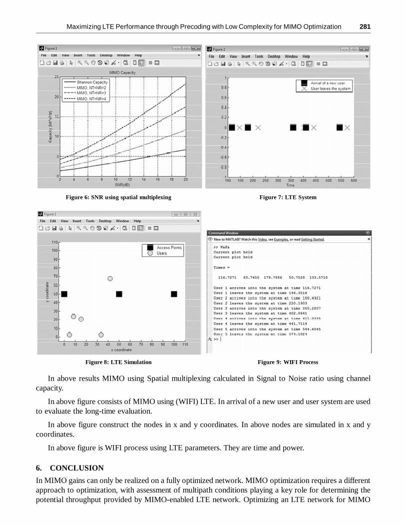
Figure 8: LTE Simulation Figure 9: WIFI Process
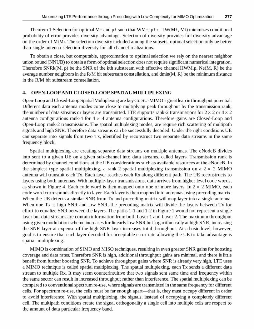
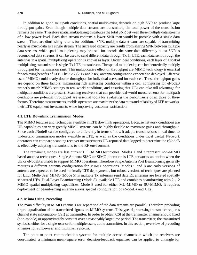
Figure 6: SNR using spatial multiplexing Figure 7: LTE System
In above results MIMO using Spatial multiplexing calculated in Signal to Noise ratio using channelcapacity.
In above figure consists of MIMO using (WIFI) LTE. In arrival of a new user and user system are usedto evaluate the long-time evaluation.
In above figure construct the nodes in x and y coordinates. In above nodes are simulated in x and ycoordinates.
In above figure is WIFI process using LTE parameters. They are time and power.
6. CONCLUSION
In MIMO gains can only be realized on a fully optimized network. MIMO optimization requires a differentapproach to optimization, with assessment of multipath conditions playing a key role for determining thepotential throughput provided by MIMO-enabled LTE network. Optimizing an LTE network for MIMO

282 N. Duraichi, and M. Suganthi
requires a new set of scanning receiver parameters and including multipath CINR measurements, CN, andCQI for all key MIMO modes. In WIFI process is optimized in the power and area. WIFI Operators can usethe knowledge gained from analysing receiver MIMO data to improve conditions in the current networkthrough antenna and eNodeB. Receiver data can also be used to evaluate the performance of UEs andeNodeB MIMO mode selection. In this work accurate data multipath conditions in existing LTE networkscan be lead better planning of future MIMO-capable networks. This will become increasingly valuable asmore users depend on LTE to provide the data rates. They are need for wireless applications for videostreaming. Operators that maximize the performance of MIMO in their LTE networks able to provide thebest service to these users with the smallest amount of infrastructure investment is advantage in both priceand quality of service.
REFERENCES[1] A. Adhikary, J. Nam, J. Y. Ahn, and G. Caire, “Joint spatial division and multiplexing—the large-scale array regime,”
IEEE Trans. Inf. Theory, vol. 59, no. 10, 2013.
[2] A. Kammoun, A. Muller, E. Bj ̈ ornson, and M. Debbah, “Linear Precoding Based on Truncated Polynomial ExpansionPart II: Large-Scale Multi-Cell Systems,” IEEE J. Sel. Topics Signal Process., Submitted, arXiv: 1310.1799.
[3] A. Muller, A. Kammoun, E. Bj ̈ ornson, and M. Debbah, “Linear precoding based on truncated polynomial expansion—Part I: Large-scale single-cell systems,” IEEE J. Sel. Topics Signal Process., Submitted, arXiv:1310.1806.
[4] D. Gesbert, S. Hanly, H. Huang, S. Shamai, O. Simeone, and W. Yu, “Multi-cell MIMO cooperative networks: A newlook at interference,” IEEE J. Sel. Areas Commun., vol. 28, no. 9, pp. 1380–1408, 2010.
[5] E. Bjornson and E. Jorswieck, “Optimal resource allocation in coordinated multi-cell systems,” Foundations and Trendsin Communications and Information Theory, 2013.
[6] F. Rusek, D. Persson, B.K. Lau, E.G. Larsson, T.L. Marzetta, O. Edfors, and F. Tufvesson, “Scaling up MIMO: Opportunitiesand Challenges with Very Large Arrays,” IEEE Signal Process. Mag., vol. 30, no. 1, pp. 40–60, 2013.
[7] H. Holma and A. Toskala, LTE advanced: 3GPP solution for IMT-Advanced, Wiley, 1st edition, 2012.
[8] J. Hoydis, S. ten Brink, and M. Debbah, “Massive MIMO in the UL/DL of cellular networks: How many antennas do weneed?,” IEEE J. Sel. Areas Commun., vol. 31, no. 2, pp. 160–171, 2013.
[9] J. Hoydis, M. Debbah, and M. Kobayashi, “Asymptotic moments for interference mitigation in correlated fading channels,”in IEEE ISIT, 2011.
[10] N. Sidiropoulos, T. Davidson, and Z.-Q. Luo, “Transmit beamforming for physical-layer multicasting,” IEEE Trans.Signal Process., vol. 54, no. 6, pp. 2239–2251, 2006.
[11] S. Zarei, W. Gerstacker, R. R. Muller, and R. Schober, “Low- ¨ complexity linear precoding for downlink large-scaleMIMO systems,” in Proc. IEEE PIMRC, 2013.
[12] T.L. Marzetta, “Noncooperative cellular wireless with unlimited numbers of base station antennas,” IEEE Trans. Commun.,vol. 9, no. 11, pp. 3590–3600, 2010.