max-e-pro™ centrifugal pumps with integral trap · the proprietors of these names and brands and...
TRANSCRIPT
IMPORTANT SAFETY INSTRUCTIONSREAD AND FOLLOW ALL INSTRUCTIONS
SAVE THESE INSTRUCTIONS
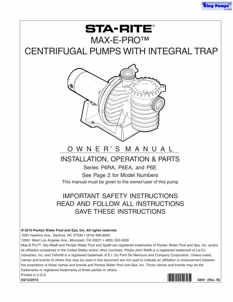
MAX-E-PRO™ CENTRIFUGAL PUMPS WITH INTEGRAL TRAP
O W N E R ’ S M A N U A L
INSTALLATION, OPERATION & PARTSSeries P6RA, P6EA, and P6E
See Page 2 for Model NumbersThis manual must be given to the owner/user of this pump
© 2010 Pentair Water Pool and Spa, Inc. All rights reserved.1620 Hawkins Ave., Sanford, NC 27330 • (919) 566-8000
10951 West Los Angeles Ave., Moorpark, CA 93021 • (805) 553-5000Max-E-Pro™, Sta-Rite® and Pentair Water Pool and Spa® are registered trademarks of Pentair Water Pool and Spa, Inc. and/or
its affiliated companies in the United States and/or other countries. Plasto-Joint Stik® is a registered trademark of La-Co
Industries, Inc. and Teflon® is a registered trademark of E.I. Du Pont De Nemours and Company Corporation. Unless noted,names and brands of others that may be used in this document are not used to indicate an affiliation or endorsement between
the proprietors of these names and brands and Pentair Water Pool and Spa, Inc. Those names and brands may be the
trademarks or registered trademarks of those parties or others.Printed in U.S.A.
03/12/2010 S691 (Rev. B)*S691*
2
‘P6RA’, P6EA’ ‘P6E’ and ‘P6R’ SERIES PUMP WITH TRAP
To avoid unneeded service calls, prevent possibleinjuries, and get the most out of your pump, READ THISMANUAL CAREFULLY!
The Sta-Rite ‘P6RA’, ‘P6EA’, ‘P6R’ and ‘P6E’ SeriesSelf-priming Centrifugal pumps:
• Are designed for use with swimming pools or ascentrifugal pumps.
Table of Contents
Safety instructions 2-3
Installation 3-5
Electrical 5-8
Operation 9-11
Storage/Winterizing 10
Pump Service 10-11
Troubleshooting Guide 12
Repair Parts List 13-15
READ AND FOLLOWSAFETY INSTRUCTIONS!
This is the safety alert symbol. When you see thissymbol on your system or in this manual, look for
one of the following signal words and be alert to thepotential for personal injury.
warns about hazards that will cause death,serious personal injury, or major property damage ifignored.
warns about hazards that can cause death,serious personal injury, or major property damage ifignored.
warns about hazards that will or can causeminor personal injury or property damage if ignored.
NOTICE indicates special instructions not related to hazards.
Carefully read and follow all safety instructions in thismanual and on equipment. Keep safety labels in goodcondition; replace if missing or damaged.
Incorrectly installed or tested equipmentmay fail, causing severe injury or propertydamage.
Read and follow instructions in owner's manual wheninstalling and operating equipment. Have a trained poolprofessional perform all pressure tests.
1. Do not connect system to a high pressure or citywater system.
Technical SupportSanford, North Carolina(8 A.M. to 5 P.M. EST)
Moorpark, California(8 A.M. to 5 P.M. PST)
Phone: (800) 831-7133Fax: (800) 284-4151
www.pentairpool.com www.staritepool.com
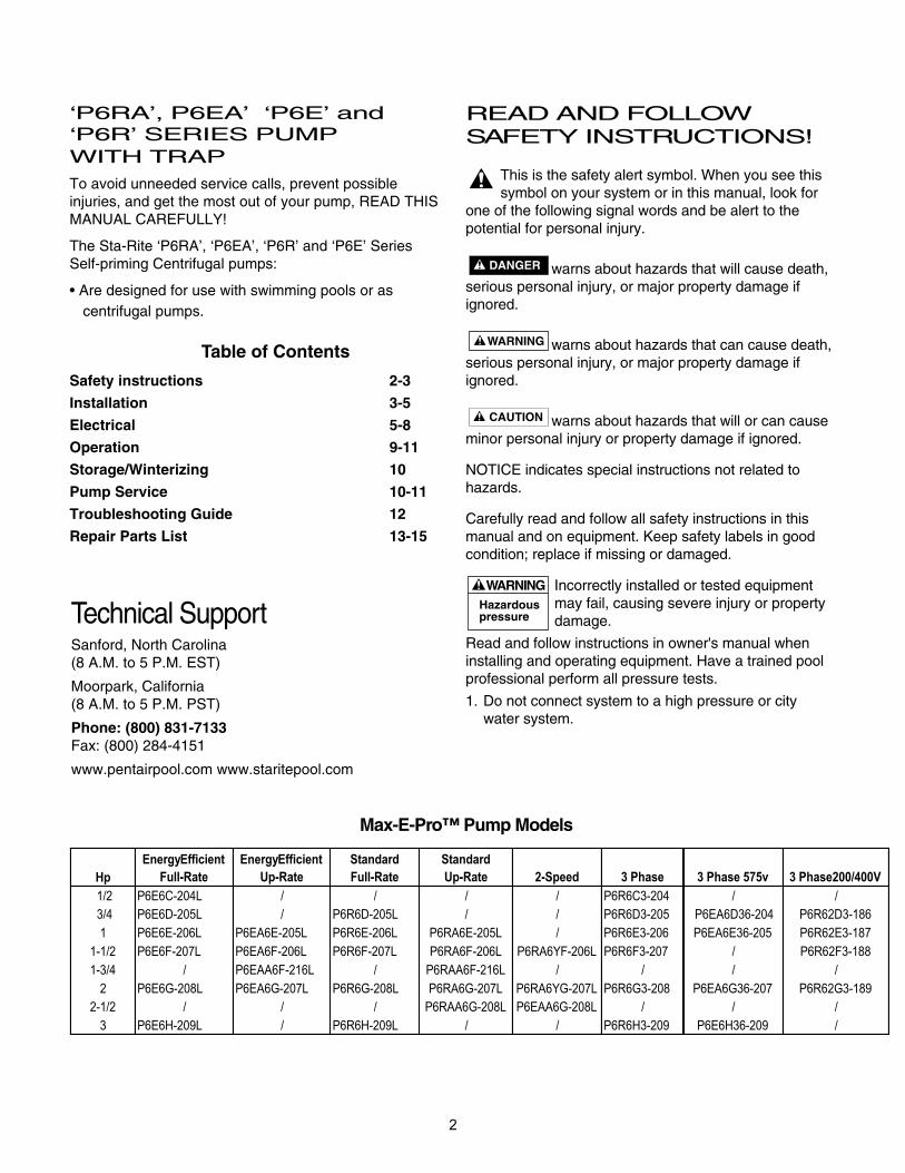
Max-E-Pro™ Pump Models
Hp
EnergyEfficient
Full-Rate
EnergyEfficient
Up-Rate
Standard
Full-Rate
Standard
Up-Rate 2-Speed 3 Phase 3 Phase 575v 3 Phase200/400V
1/2 P6E6C-204L / / / / P6R6C3-204 / /
3/4 P6E6D-205L / P6R6D-205L / / P6R6D3-205 P6EA6D36-204 P6R62D3-186
1 P6E6E-206L P6EA6E-205L P6R6E-206L P6RA6E-205L / P6R6E3-206 P6EA6E36-205 P6R62E3-187
1-1/2 P6E6F-207L P6EA6F-206L P6R6F-207L P6RA6F-206L P6RA6YF-206L P6R6F3-207 / P6R62F3-188
1-3/4 / P6EAA6F-216L / P6RAA6F-216L / / / /
2 P6E6G-208L P6EA6G-207L P6R6G-208L P6RA6G-207L P6RA6YG-207L P6R6G3-208 P6EA6G36-207 P6R62G3-189
2-1/2 / / / P6RAA6G-208L P6EAA6G-208L / / /
3 P6E6H-209L / P6R6H-209L / / P6R6H3-209 P6E6H36-209 /
2. Use equipment only in a pool or spa installation.
3. Install pump with at least two (2) hydraulicallybalanced main drains equipped with correctlyinstalled, screw-fastened, anti-entrapment certifiedcovers. See Page 4.
4. Trapped air in system can cause explosion. BE SURE all air is out of system before operating or testing equipment.
Before pressure testing, make the following safetychecks:
• Check all clamps, bolts, lids, and system accessoriesbefore testing.
• Release all air in system before testing.
• Water pressure for test must be less than 25 PSI(7.5 kg/cm2).
• Water Temperature for test must be less than 100o F(38o C).
• Limit test to 24 hours. After test, visually checksystem to be sure it is ready for operation. Removetrap lid and retighten hand tight only.
NOTICE: These parameters apply to Sta-Riteequipment only. For non-Sta-Rite equipment, consultmanufacturer.
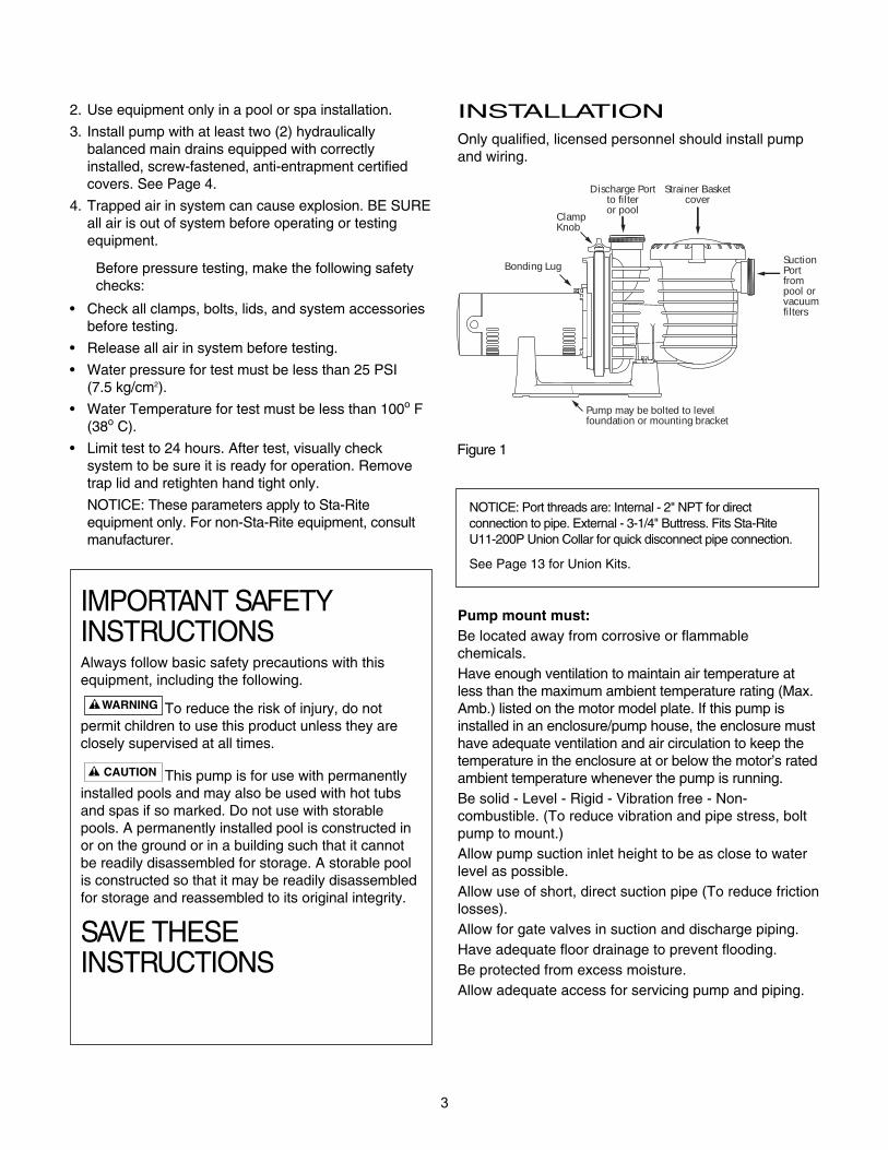
INSTALLATIONOnly qualified, licensed personnel should install pumpand wiring.
Pump mount must:Be located away from corrosive or flammablechemicals.Have enough ventilation to maintain air temperature atless than the maximum ambient temperature rating (Max.Amb.) listed on the motor model plate. If this pump isinstalled in an enclosure/pump house, the enclosure musthave adequate ventilation and air circulation to keep thetemperature in the enclosure at or below the motor’s ratedambient temperature whenever the pump is running.Be solid - Level - Rigid - Vibration free - Non-combustible. (To reduce vibration and pipe stress, boltpump to mount.)Allow pump suction inlet height to be as close to waterlevel as possible.Allow use of short, direct suction pipe (To reduce frictionlosses).Allow for gate valves in suction and discharge piping.Have adequate floor drainage to prevent flooding.Be protected from excess moisture.Allow adequate access for servicing pump and piping.
3
IMPORTANT SAFETY INSTRUCTIONSAlways follow basic safety precautions with thisequipment, including the following.
To reduce the risk of injury, do notpermit children to use this product unless they areclosely supervised at all times.
This pump is for use with permanentlyinstalled pools and may also be used with hot tubsand spas if so marked. Do not use with storablepools. A permanently installed pool is constructed inor on the ground or in a building such that it cannotbe readily disassembled for storage. A storable poolis constructed so that it may be readily disassembledfor storage and reassembled to its original integrity.
SAVE THESE INSTRUCTIONS
SuctionPort frompool orvacuumfilters
Strainer Basketcover
Discharge Portto filteror pool
ClampKnob
Bonding Lug
Pump may be bolted to level foundation or mounting bracket
4284 1102
Figure 1
NOTICE: Port threads are: Internal - 2" NPT for directconnection to pipe. External - 3-1/4" Buttress. Fits Sta-RiteU11-200P Union Collar for quick disconnect pipe connection.
See Page 13 for Union Kits.
4
Fire and burn hazard. Modern motors run athigh temperatures. To reduce the risk of fire, do not allowleaves, debris, or foreign matter to collect around thepump motor. To avoid burns when handling the motor, letit cool for 20 minutes before trying to work on it.NOTICE: Use Teflon® tape or Plasto-Joint Stik® formaking all threaded connections to the pump. Do not usepipe dope; pipe dope will cause stress cracking in thepump.NOTICE: Pump suction and discharge connections havemolded in thread stops. DO NOT try to screw pipe inbeyond these stops.
Teflon Taping Instructions:Use only new or clean PVC pipe fittings.Wrap male pipe threads with one to two layers of Teflontape. Cover entire threaded portion of pipe.Do not overtighten or tighten past thread stop in pump port!If leaks occur, remove pipe, clean off old tape, rewrapwith one to two additional layers of tape and remake theconnection.NOTICE: Support all piping connected with pump!
Piping:Use at least 2" IPS PVC (51mm) pipe. Increase size if along run is needed. To avoid strains on the pump, support both suction anddischarge pipes independently. Place these supportsnear the pump.To avoid a strain left by a gap at the last connection, startall piping at the pump and run pipe away from the pump.Never use a suction pipe smaller than pump suction connection.To avoid airlocking, slope suction pipe slightly upwardtoward the pump.NOTICE: To prevent flooding when removing pump forservice, all flooded suction systems must have gatevalves in suction and discharge pipes.
Fittings:Fittings restrict flow; for best efficiency use fewestpossible fittings.Avoid fittings which could cause an air trap.Pool fittings must conform to International Association ofPlumbing and Mechanical Officials (IAPMO) standards.Use only non-entrapping suction fitting or double suction.
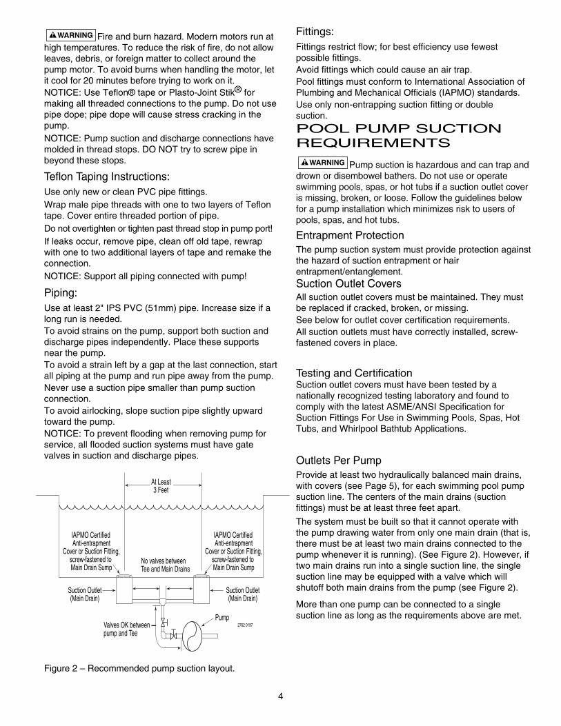
POOL PUMP SUCTION REQUIREMENTS
Pump suction is hazardous and can trap anddrown or disembowel bathers. Do not use or operateswimming pools, spas, or hot tubs if a suction outlet coveris missing, broken, or loose. Follow the guidelines belowfor a pump installation which minimizes risk to users ofpools, spas, and hot tubs.
Entrapment ProtectionThe pump suction system must provide protection againstthe hazard of suction entrapment or hairentrapment/entanglement.Suction Outlet CoversAll suction outlet covers must be maintained. They mustbe replaced if cracked, broken, or missing. See below for outlet cover certification requirements.All suction outlets must have correctly installed, screw-fastened covers in place.
Testing and CertificationSuction outlet covers must have been tested by anationally recognized testing laboratory and found tocomply with the latest ASME/ANSI Specification forSuction Fittings For Use in Swimming Pools, Spas, HotTubs, and Whirlpool Bathtub Applications.
Outlets Per PumpProvide at least two hydraulically balanced main drains,with covers (see Page 5), for each swimming pool pumpsuction line. The centers of the main drains (suctionfittings) must be at least three feet apart.
The system must be built so that it cannot operate withthe pump drawing water from only one main drain (that is,there must be at least two main drains connected to thepump whenever it is running). (See Figure 2). However, iftwo main drains run into a single suction line, the singlesuction line may be equipped with a valve which willshutoff both main drains from the pump (see Figure 2).
More than one pump can be connected to a singlesuction line as long as the requirements above are met.
At Least3 Feet
Suction Outlet(Main Drain)
Suction Outlet(Main Drain)
IAPMO Certified Anti-entrapment
Cover or Suction Fitting,screw-fastened to Main Drain Sump
IAPMO Certified Anti-entrapment
Cover or Suction Fitting,screw-fastened to Main Drain Sump
PumpValves OK betweenpump and Tee
No valves betweenTee and Main Drains
2762 0197
Figure 2 – Recommended pump suction layout.
5
Water VelocityThe maximum water velocity through any suction outletmust be 1.5 feet per second unless the outlet complieswith the latest ASME/SNSI Specification for SuctionFittings For Use in Swimming Pools, Spas, Hot Tubs,and Whirlpool Bathtub Applications. In any case, do notexceed the suction fittings maximum designed flow rate.
If 100% of the pump’s flow comes from the main drainsystem, the maximum water velocity in the pumpsuction hydraulic system must be six feet per second orless even if one main drain (suction fitting) is completelyblocked. The flow through the remaining main drain(s)must comply with the latest ASME/ANSI Specificationfor Suction Fittings For Use in Swimming Pools, Spas,Hot Tubs, and Whirlpool Bathtub Applications.
ELECTRICALNoticeDue to wide variation in electrical equipment, powersupply, and installation requirements, this manual doesnot make specific recommendations concerningauxiliary equipment or fusing/wiring.
Wire sizing, wire type, branch circuit fuse protection,motor starter, control equipment, and related items mustmeet National Electrical Code and local coderequirements. Motors are supplied by severalmanufacturers and nameplate data (service factor,maximum amperage, etc.) will vary. Consult controlmanufacturer and motor nameplate on your pump tocorrectly choose and size motor starter and controlequipment for your particular installation. Specificelectrical questions or problems should be addressed tothe manufacturer of the electrical component inquestion.
Ground motor before connecting to electricalpower supply. Failure to ground motor can cause
severe or fatal electrical shock hazard.
Do not ground to a gas supply line.
To avoid dangerous or fatal electrical shock, turnOFF power to motor before working on electrical
connections.
Ground Fault Circuit Interrupter (GFCI) trippingindicates an electrical problem. If GFCI trips and
will not reset, have a qualified electrician inspect andrepair electrical system.
Exactly match supply voltage to nameplatevoltage. Incorrect voltage can cause fire or
seriously damage motor and voids warranty. If in doubtconsult a licensed electrician.
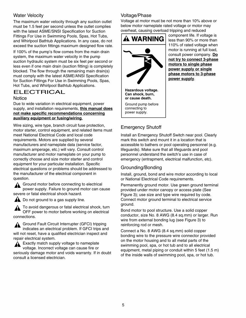
Voltage/PhaseVoltage at motor must be not more than 10% above orbelow motor nameplate rated voltage or motor mayoverheat, causing overload tripping and reduced
component life. If voltage isless than 90% or more than110% of rated voltage whenmotor is running at full load,consult power company. Donot try to connect 3-phasemotors to single phasepower supply or singlephase motors to 3-phasepower supply.
Emergency Shutoff
Install an Emergency Shutoff Switch near pool. Clearlymark this switch and mount it in a location that isaccessible to bathers or pool operating personnel (e.g.lifeguards). Make sure that all lifeguards and poolpersonnel understand the switch’s use in case ofemergency (entrapment, electrical malfunction, etc).
Grounding/BondingInstall, ground, bond and wire motor according to localor National Electrical Code requirements.
Permanently ground motor. Use green ground terminalprovided under motor canopy or access plate (SeeFigure 3); use size and type wire required by code.Connect motor ground terminal to electrical serviceground.
Bond motor to pool structure. Use a solid copperconductor, size No. 8 AWG (8.4 sq.mm) or larger. Runwire from external bonding lug (see Figure 3) to reinforcing rod or mesh.
Connect a No. 8 AWG (8.4 sq.mm) solid copperbonding wire to the pressure wire connector providedon the motor housing and to all metal parts of theswimming pool, spa, or hot tub and to all electricalequipment, metal piping or conduit within 5 feet (1.5 m)of the inside walls of swimming pool, spa, or hot tub.
Hazardous voltage.Can shock, burn,or cause death.
Ground pump beforeconnecting topower supply.
6
Figure 4B Voltage ChangePlug Set for 115 Volts
Figure 4A -Voltage ChangePlug Set for 230 Volts
Figure 3: Typical ground screw
BONDINGLUG
GREEN GROUND
SCREW
510 0993
WIRING3 Phase Wiring - Wire a Single Speed, Single Voltage, 3Phase Motor.Notice: 3 phase models require magnetic motor startersand external overload protection. If in doubt about theprocedure, consult a licensed electrician. Be sure the wireand circuit breaker sizes match the pump motor rating(Table II; Page 8). There are three terminals labeled L1,L2, and L3 (or LINE A, LINE B, and LINE C) on the pumpmotor. Attach the power leads to these terminals asspecified on the pump motor wiring label. Check for properpump motor rotation. If motor is not running properly,switch any two of the three input wires. Verify proper pumpmotor rotation.
1. Turn off power.
2. Remove the motor end cover.
To Wire a Single Speed, Single Voltage MotorThere are two terminals labeled L1 and L2. Attach the powerleads to these terminals. Either wire may attach to eitherterminal.
To Wire a Dual-Voltage MotorDual voltage motors have a plug to change from 230 volts(factory setting) to 115 volts).
1. If you have 230 volts motor supply voltage, confirm that theplug is set for 230 volts. The arrow on the plug will point tothe 230 volt position. Note that plug only connects with oneprong in this position.
2. If you have 115 volt supply, pull the plug straight up andplace it on the two brass prongs as shown.
NOTE: Arrow is highlighted for clarity.
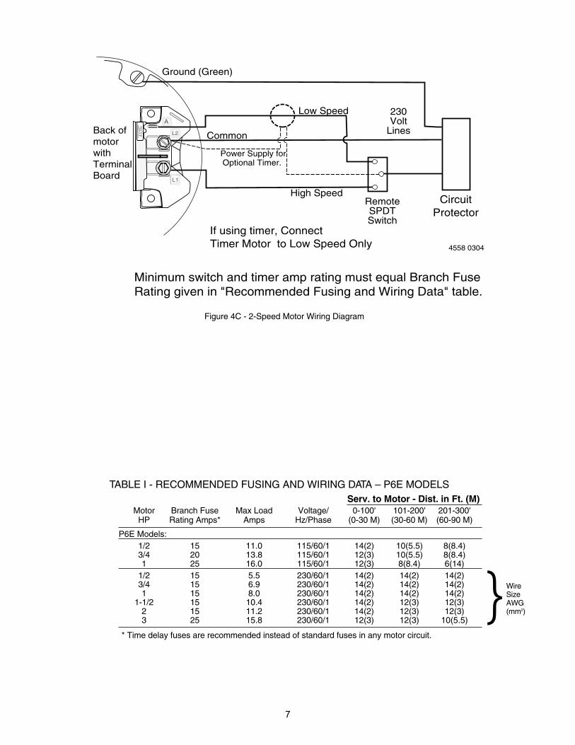
To Wire a Two-Speed MotorWire the pump as shown in the diagram.
Note: For 575 VAC models, consult a licensed electrician.
Pump must be permanently connected to circuit. See Figures 4Aand 4B for wiring connection diagrams. Match wire and circuitbreaker sizes to correct Fusing and Wiring Data Chart (Page 7).If other lights or appliances are also on the same circuit, be sureto add their amp loads to pump amp load. (If unsure how to dothis or if this is confusing, consult a licensed electrician.) Use theload circuit breaker as the master on-off switch.
Install a Ground Fault Circuit Interrupter (GFCI) in circuit; it willsense a short-circuit to ground and disconnect power before itbecomes dangerous to pool users. For size of GFCI requiredand test procedures for GFCI, see manufacturer’s instructions.
In case of power outage, check GFCI for tripping (which willprevent normal water circulation). Reset if necessary.
NOTICE: If you do not use conduit when wiring motor, be sure toseal wire opening on end of motor to prevent dirt, bugs, etc.,from entering motor.
Risk of dangerous or fatal electrical shock. Be surethat power to the motor circuit is off before working on wiring,wiring connections, or motor. Re-install the motor end cover andall other wiring covers before turning on the power.
7
WireSizeAWG(mm2)}
TABLE I - RECOMMENDED FUSING AND WIRING DATA – P6E MODELSServ. to Motor - Dist. in Ft. (M)
Motor Branch Fuse Max Load Voltage/ 0-100' 101-200' 201-300'HP Rating Amps* Amps Hz/Phase (0-30 M) (30-60 M) (60-90 M)
P6E Models:1/2 15 11.0 115/60/1 14(2) 10(5.5) 8(8.4)3/4 20 13.8 115/60/1 12(3) 10(5.5) 8(8.4)1 25 16.0 115/60/1 12(3) 8(8.4) 6(14)
1/2 15 5.5 230/60/1 14(2) 14(2) 14(2)3/4 15 6.9 230/60/1 14(2) 14(2) 14(2)1 15 8.0 230/60/1 14(2) 14(2) 14(2)
1-1/2 15 10.4 230/60/1 14(2) 12(3) 12(3)2 15 11.2 230/60/1 14(2) 12(3) 12(3)3 25 15.8 230/60/1 12(3) 12(3) 10(5.5)
* Time delay fuses are recommended instead of standard fuses in any motor circuit.
Figure 4C - 2-Speed Motor Wiring Diagram
L2
=C
OM
L
1=
HI
A=
LO
W
A
L2
L1
Power Supply forOptional Timer.
Low Speed
High SpeedCircuit
ProtectorRemoteSPDTSwitch
Ground (Green)
Common
If using timer, Connect Timer Motor to Low Speed Only
Minimum switch and timer amp rating must equal Branch FuseRating given in "Recommended Fusing and Wiring Data" table.
230Volt
LinesBack ofmotorwith TerminalBoard
4558 0304
8
WireSizeAWG(mm2)}
Motor
HP
Branch Fuse
Rating Amps*
Max Load
Amps
Voltage/
Hz/Phase
0-100'
(0-30 M)
101-200'
(30-60 M)
201-300'
(60-90 M)
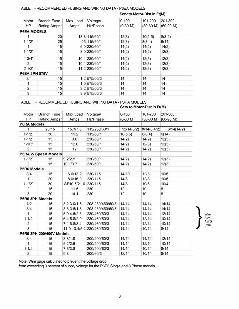
1 20 13.8 115/60/1 12(3) 10(5.5) 8(8.4)
1-1/2` 25 16 115/60/1 12(3) 8(8.4) 6(14)
1 15 6.9 230/60/1 14(2) 14(2) 14(2)
1-1/2` 15 8.0 230/60/1 14(2) 14(2) 12(3)
1-3/4' 15 10.4 230/60/1 14(2) 12(3) 12(3)
2 15 10.4 230/60/1 14(2) 12(3) 12(3)
2-1/2' 15 11.2 230/60/1 14(2) 12(3) 12(3)
P6EA 3PH 575V
3/4 15 1.2 575/60/3 14 14 14
1 15 1.5 575/60/3 14 14 14
2 15 3.2 575/60/3 14 14 14
3 15 3.9 575/60/3 14 14 14
Motor
HP
Branch Fuse
Rating Amps*
Max Load
Amps
Voltage/
Hz/Phase
0-100'
(0-30 M)
101-200'
(30-60 M)
201-300'
(60-90 M)
P6RA Models
1 20/15 15.3/7.6 115/230/60/1 12/14(3/2) 8/14(8.4/2) 6/14(14/2)
1-1/2` 30 19.2 115/60/1 10(5.5) 8(8.4) 6(14)
1-1/2` 15 9.6 230/60/1 14(2) 14(2) 12(3)
1-1/3' 15 12.0 230/60/1 14(2) 12(3) 12(3)
2 15 12 230/60/1 14(2) 14(2) 12(3)
1-1/2` 15 9.2/2.5 230/60/1 14(2) 14(2) 12(3)
2 15 10.1/3.7 230/60/1 14(2) 14(2) 12(3)
3/4 15 6.6/13.2 230/115 14/10 12/8 10/6
1 20 8.0/16.0 230/115 14/8 12/8 10/6
1-1/2` 30 SF10.5/21.0 230/115 14/8 10/6 10/4
2 15 11.5 230 12 10 8
3 20 14.1 230 12 10 8
P6R6 3PH Models
1/2 15 3.2-3.0/1.5 208-230/460/60/3 14/14 14/14 14/14
3/4 15 3.8-3.6/1.8 208-230/460/60/3 14/14 14/14 14/14
1 15 5.0-4.6/2.3 230/460/60/3 14/14 14/14 12/14
1-1/2 15 6.4-5.8/2.9 230/460/60/3 14/14 12/14 10/14
2 15 7.1-6.8/3.4 230/460/60/3 14/14 12/14 10/14
3 15 11.0-10.4/5.2 230/460/60/3 14/14 10/14 8/14
P6R6 3PH 200/400V Models
3/4 15 3.8/1.9 200/400/60/3 14/14 14/14 12/14
1 15 5.2/2.6 200/400/60/3 14/14 12/14 10/14
1-1/2 15 7.6/3.8 200/400/60/3 14/14 10/14 8/14
2 15 9.8 200/60/3 12/14 10/14 8/14
P6EA MODELS
P6RA 2- Speed Models
P6R6 Models
TABLE II - RECOMMENDED FUSING AND WIRING DATA - P6EA MODELS
Note: Wire gage calculated to prevent the voltage drop from exceeding 3 percent of supply voltage for the P6R6 Single and 3 Phase models.
Serv.to Motor-Dist.in Ft(M)
TABLE III - RECOMMENDED FUSING AND WIRING DATA - P6RA MODELSServ.to Motor-Dist.in Ft(M)
9
OPERATIONNEVER run pump dry. Running pump dry maydamage seals, causing leakage and flooding. Fill
pump with water before starting motor.
Before removing trap cover:
1. STOP PUMP before proceeding.2. CLOSE GATE VALVES in suction and dischargepipes.3. RELEASE ALL PRESSURE from pump and piping system.4. NEVER tighten or loosen clamp while pump is operating!
If pump is being pressure tested, be sure pressurehas been released beforeremoving trap cover.
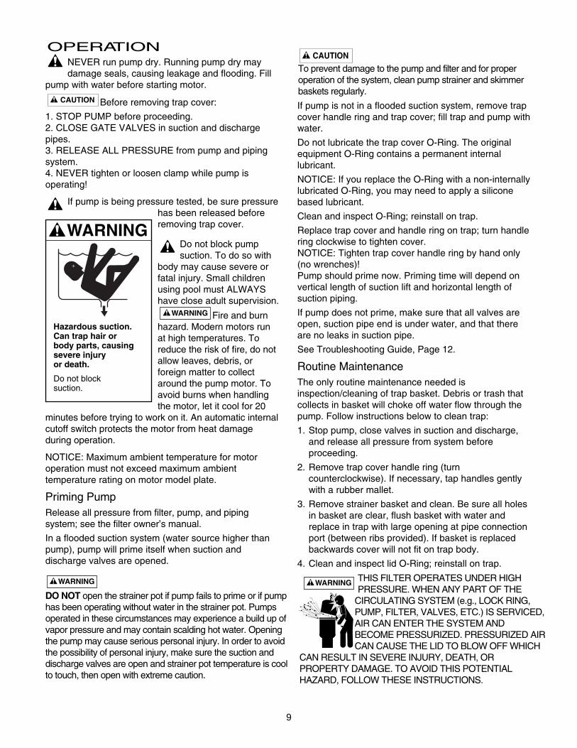
Do not block pumpsuction. To do so with
body may cause severe orfatal injury. Small childrenusing pool must ALWAYShave close adult supervision.
Fire and burnhazard. Modern motors runat high temperatures. Toreduce the risk of fire, do notallow leaves, debris, orforeign matter to collectaround the pump motor. Toavoid burns when handlingthe motor, let it cool for 20
minutes before trying to work on it. An automatic internalcutoff switch protects the motor from heat damageduring operation.
NOTICE: Maximum ambient temperature for motoroperation must not exceed maximum ambienttemperature rating on motor model plate.
Priming PumpRelease all pressure from filter, pump, and pipingsystem; see the filter owner’s manual.
In a flooded suction system (water source higher thanpump), pump will prime itself when suction anddischarge valves are opened.
If pump is not in a flooded suction system, remove trapcover handle ring and trap cover; fill trap and pump withwater.
Do not lubricate the trap cover O-Ring. The originalequipment O-Ring contains a permanent internal lubricant.
NOTICE: If you replace the O-Ring with a non-internallylubricated O-Ring, you may need to apply a siliconebased lubricant.
Clean and inspect O-Ring; reinstall on trap.
Replace trap cover and handle ring on trap; turn handlering clockwise to tighten cover.NOTICE: Tighten trap cover handle ring by hand only(no wrenches)! Pump should prime now. Priming time will depend onvertical length of suction lift and horizontal length ofsuction piping.
If pump does not prime, make sure that all valves areopen, suction pipe end is under water, and that thereare no leaks in suction pipe.
See Troubleshooting Guide, Page 12.
Routine MaintenanceThe only routine maintenance needed isinspection/cleaning of trap basket. Debris or trash thatcollects in basket will choke off water flow through thepump. Follow instructions below to clean trap:
1. Stop pump, close valves in suction and discharge,and release all pressure from system beforeproceeding.
2. Remove trap cover handle ring (turncounterclockwise). If necessary, tap handles gentlywith a rubber mallet.
3. Remove strainer basket and clean. Be sure all holesin basket are clear, flush basket with water andreplace in trap with large opening at pipe connectionport (between ribs provided). If basket is replacedbackwards cover will not fit on trap body.
4. Clean and inspect lid O-Ring; reinstall on trap.
Hazardous suction.Can trap hair orbody parts, causingsevere injuryor death.
Do not blocksuction.
DO NOT open the strainer pot if pump fails to prime or if pumphas been operating without water in the strainer pot. Pumpsoperated in these circumstances may experience a build up ofvapor pressure and may contain scalding hot water. Openingthe pump may cause serious personal injury. In order to avoidthe possibility of personal injury, make sure the suction anddischarge valves are open and strainer pot temperature is coolto touch, then open with extreme caution.
To prevent damage to the pump and filter and for properoperation of the system, clean pump strainer and skimmerbaskets regularly.
THIS FILTER OPERATES UNDER HIGHPRESSURE. WHEN ANY PART OF THE
CIRCULATING SYSTEM (e.g., LOCK RING,PUMP, FILTER, VALVES, ETC.) IS SERVICED,AIR CAN ENTER THE SYSTEM ANDBECOME PRESSURIZED. PRESSURIZED AIRCAN CAUSE THE LID TO BLOW OFF WHICH
CAN RESULT IN SEVERE INJURY, DEATH, ORPROPERTY DAMAGE. TO AVOID THIS POTENTIALHAZARD, FOLLOW THESE INSTRUCTIONS.
10
5. Clean O-Ring groove on trap body and replace coverand handle ring. To help keep cover from sticking,
tighten hand tight only.
6. Prime pump (see priminginstructions).
Draining Pump1. Pump down water level
below all inlets to the pool.
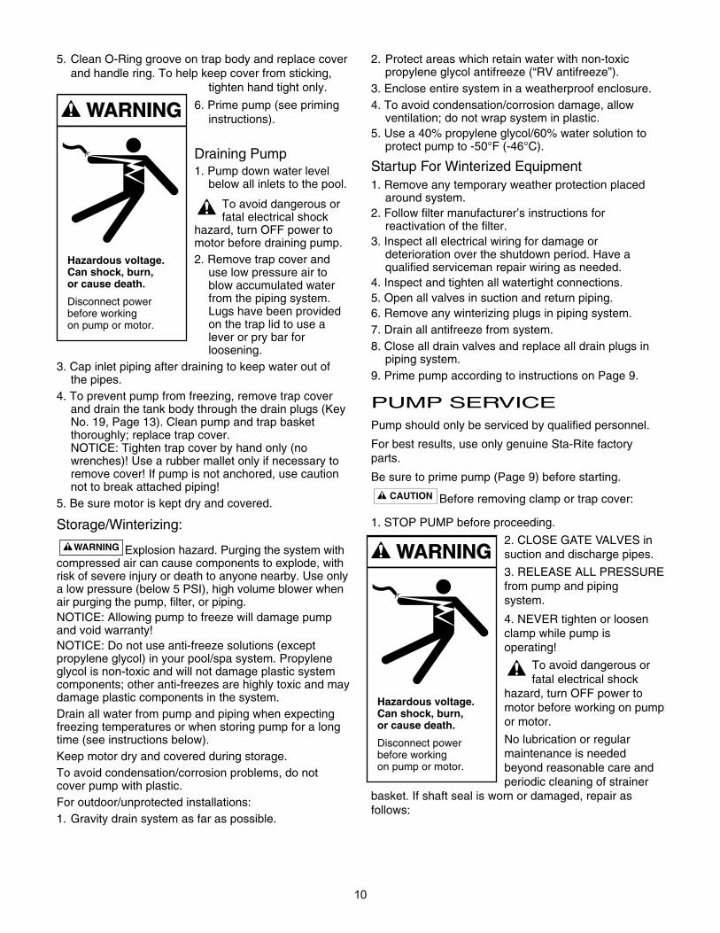
To avoid dangerous orfatal electrical shock
hazard, turn OFF power tomotor before draining pump.2. Remove trap cover and
use low pressure air toblow accumulated waterfrom the piping system.Lugs have been providedon the trap lid to use alever or pry bar forloosening.
3. Cap inlet piping after draining to keep water out ofthe pipes.
4. To prevent pump from freezing, remove trap coverand drain the tank body through the drain plugs (KeyNo. 19, Page 13). Clean pump and trap basketthoroughly; replace trap cover.NOTICE: Tighten trap cover by hand only (nowrenches)! Use a rubber mallet only if necessary toremove cover! If pump is not anchored, use cautionnot to break attached piping!
5. Be sure motor is kept dry and covered.
Storage/Winterizing:
Explosion hazard. Purging the system withcompressed air can cause components to explode, withrisk of severe injury or death to anyone nearby. Use onlya low pressure (below 5 PSI), high volume blower whenair purging the pump, filter, or piping.NOTICE: Allowing pump to freeze will damage pumpand void warranty!NOTICE: Do not use anti-freeze solutions (exceptpropylene glycol) in your pool/spa system. Propyleneglycol is non-toxic and will not damage plastic systemcomponents; other anti-freezes are highly toxic and maydamage plastic components in the system.Drain all water from pump and piping when expectingfreezing temperatures or when storing pump for a longtime (see instructions below).Keep motor dry and covered during storage.To avoid condensation/corrosion problems, do notcover pump with plastic.For outdoor/unprotected installations:1. Gravity drain system as far as possible.
2. Protect areas which retain water with non-toxicpropylene glycol antifreeze (“RV antifreeze”).
3. Enclose entire system in a weatherproof enclosure.4. To avoid condensation/corrosion damage, allow
ventilation; do not wrap system in plastic.5. Use a 40% propylene glycol/60% water solution to
protect pump to -50°F (-46°C).
Startup For Winterized Equipment1. Remove any temporary weather protection placed
around system.2. Follow filter manufacturer’s instructions for
reactivation of the filter.3. Inspect all electrical wiring for damage or
deterioration over the shutdown period. Have aqualified serviceman repair wiring as needed.
4. Inspect and tighten all watertight connections.5. Open all valves in suction and return piping.6. Remove any winterizing plugs in piping system.7. Drain all antifreeze from system.8. Close all drain valves and replace all drain plugs in
piping system.9. Prime pump according to instructions on Page 9.
PUMP SERVICEPump should only be serviced by qualified personnel.
For best results, use only genuine Sta-Rite factoryparts.
Be sure to prime pump (Page 9) before starting.
Before removing clamp or trap cover:
1. STOP PUMP before proceeding.
2. CLOSE GATE VALVES insuction and discharge pipes.
3. RELEASE ALL PRESSUREfrom pump and piping system.
4. NEVER tighten or loosenclamp while pump is operating!
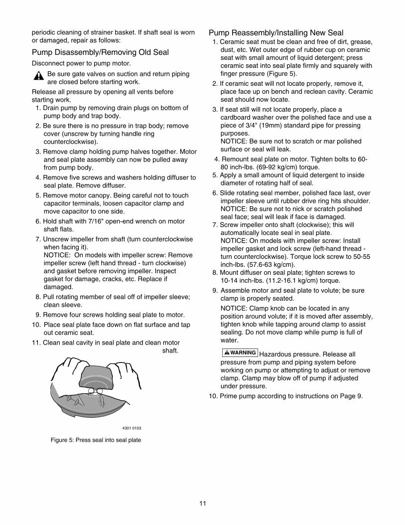
To avoid dangerous orfatal electrical shock
hazard, turn OFF power tomotor before working on pumpor motor.
No lubrication or regularmaintenance is neededbeyond reasonable care andperiodic cleaning of strainer
basket. If shaft seal is worn or damaged, repair asfollows:
Hazardous voltage.Can shock, burn,or cause death.
Disconnect powerbefore workingon pump or motor.
Hazardous voltage.Can shock, burn,or cause death.
Disconnect powerbefore workingon pump or motor.
11
periodic cleaning of strainer basket. If shaft seal is wornor damaged, repair as follows:
Pump Disassembly/Removing Old SealDisconnect power to pump motor.
Be sure gate valves on suction and return pipingare closed before starting work.
Release all pressure by opening all vents beforestarting work.
1. Drain pump by removing drain plugs on bottom ofpump body and trap body.
2. Be sure there is no pressure in trap body; removecover (unscrew by turning handle ringcounterclockwise).
3. Remove clamp holding pump halves together. Motorand seal plate assembly can now be pulled awayfrom pump body.
4. Remove five screws and washers holding diffuser toseal plate. Remove diffuser.
5. Remove motor canopy. Being careful not to touchcapacitor terminals, loosen capacitor clamp andmove capacitor to one side.
6. Hold shaft with 7/16" open-end wrench on motorshaft flats.
7. Unscrew impeller from shaft (turn counterclockwisewhen facing it). NOTICE: On models with impeller screw: Removeimpeller screw (left hand thread - turn clockwise)and gasket before removing impeller. Inspectgasket for damage, cracks, etc. Replace ifdamaged.
8. Pull rotating member of seal off of impeller sleeve;clean sleeve.
9. Remove four screws holding seal plate to motor.
10. Place seal plate face down on flat surface and tapout ceramic seat.
11. Clean seal cavity in seal plate and clean motorshaft.
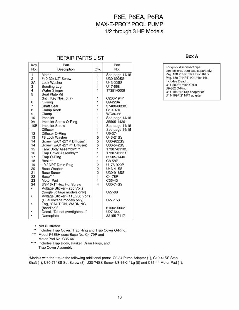
Pump Reassembly/Installing New Seal1. Ceramic seat must be clean and free of dirt, grease,
dust, etc. Wet outer edge of rubber cup on ceramicseat with small amount of liquid detergent; pressceramic seat into seal plate firmly and squarely withfinger pressure (Figure 5).
2. If ceramic seat will not locate properly, remove it,place face up on bench and reclean cavity. Ceramicseat should now locate.
3. If seat still will not locate properly, place acardboard washer over the polished face and use apiece of 3/4" (19mm) standard pipe for pressingpurposes. NOTICE: Be sure not to scratch or mar polishedsurface or seal will leak.
4. Remount seal plate on motor. Tighten bolts to 60-80 inch-lbs. (69-92 kg/cm) torque.
5. Apply a small amount of liquid detergent to insidediameter of rotating half of seal.
6. Slide rotating seal member, polished face last, overimpeller sleeve until rubber drive ring hits shoulder.NOTICE: Be sure not to nick or scratch polishedseal face; seal will leak if face is damaged.
7. Screw impeller onto shaft (clockwise); this willautomatically locate seal in seal plate.NOTICE: On models with impeller screw: Installimpeller gasket and lock screw (left-hand thread -turn counterclockwise). Torque lock screw to 50-55inch-lbs. (57.6-63 kg/cm).
8. Mount diffuser on seal plate; tighten screws to 10-14 inch-lbs. (11.2-16.1 kg/cm) torque.
9. Assemble motor and seal plate to volute; be sureclamp is properly seated.
NOTICE: Clamp knob can be located in anyposition around volute; if it is moved after assembly,tighten knob while tapping around clamp to assistsealing. Do not move clamp while pump is full ofwater.
Hazardous pressure. Release allpressure from pump and piping system beforeworking on pump or attempting to adjust or removeclamp. Clamp may blow off of pump if adjustedunder pressure.
10. Prime pump according to instructions on Page 9.
4301 0103
Figure 5: Press seal into seal plate

12
TROUBLESHOOTINGGUIDE
Read and understand safety and operatinginstructions in this manual before doing any work
on pump!
Only qualified personnel should electrically testpump motor!
FAILURE TO PUMP; REDUCED CAPACITY ORDISCHARGE PRESSURE
Suction leaks/lost prime:
1. Pump must be primed; make sure that pump voluteand trap are full of water. See priming instructions,Page 8.
2. Make sure there are no leaks in suction piping.
3. Make sure suction pipe inlet is well below the waterlevel to prevent pump from sucking air.
4. Suction lift of 10 to 20 feet (3-6 M) will reduceperformance. Suction lift of more than 20 feet (6 M)will prevent pumping and cause pump to loseprime. In either case, move pump closer (vertically)to water source. Make sure suction pipe is largeenough.
Clogged pipe/trap/impeller, worn impeller:
5. Make sure suction trap is not clogged; if it is, cleantrap and strainer.
6. Make sure impeller is not clogged (follow steps 1through 7 under “Removing Old Seal”, Page 11;check impeller for clogging; follow steps 7 through10 under “Installing New Seal”, Page 10, forreassembly).
7. Impeller and diffuser may be worn. If so, orderreplacement parts from Repair Parts List, Page 13.
8. Pump may be trying to push too high a column ofwater. If so, a “higher head” pump is needed.
Electrical:
9. Pump may be running tooslowly; check voltage atmotor terminals and atmeter while pump isrunning. If low, see wiringinstructions or consultpower company. Checkfor loose connections.
10. Pump may be too hot.A. Check line voltage; if
less than 90% or morethan 110% of ratedvoltage consult alicensed electrician.
B. Increase ventilation.C. Reduce ambient
temperature.D. Tighten any loose connections.
MECHANICAL TROUBLES AND NOISE
1. If suction and discharge piping are not adequatelysupported, pump assembly will be strained. See“Installation”, Page 3.
2. Do not mount pump on a wooden platform! Securelymount on concrete platform for quietestperformance.
Hazardous voltage.Can shock, burn,or cause death.
Disconnect powerbefore workingon pump or motor.
13
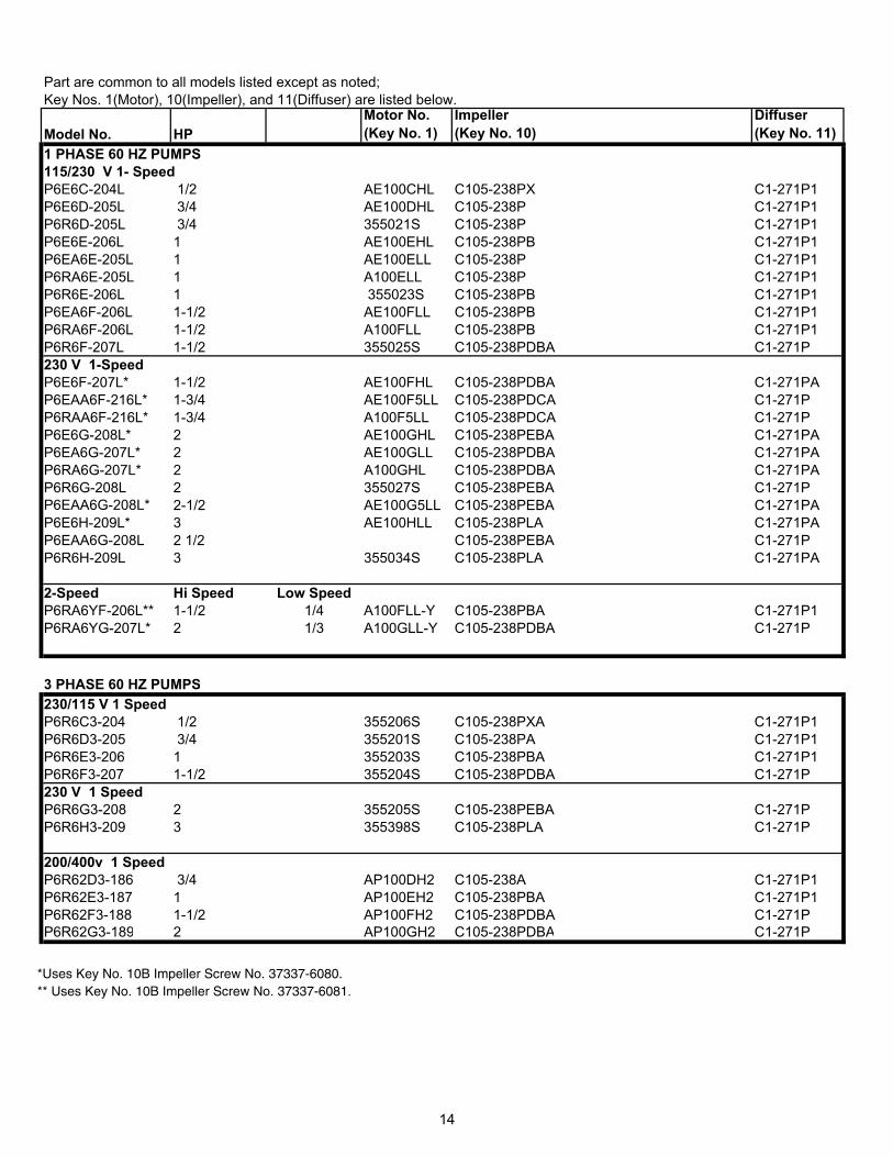
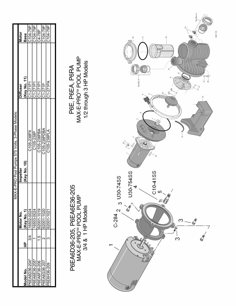
Key Part Part No. Description Qty. No.
1 Motor 1 See page 14/152 #10-32x1/2” Screw 1 U30-692SS2A Lock Washer 1 U43-22SS3 Bonding Lug 1 U17-5684 Water Slinger 1 17351-00095 Seal Plate Kit
(Incl. Key Nos. 6, 7) 1 C203-194P6 O-Ring 1 U9-228A7 Shaft Seal 1 37400-0028S8 Clamp Knob 1 C19-37A9 Clamp 1 WC36-2210 Impeller 1 See page 14/15
10A Impeller Screw O-Ring 1 35505-142610B Impeller Screw 1 See page 14/15
11 Diffuser 1 See page 14/1512 Diffuser O-Ring 1 U9-37413 #8 Lock Washer 5 U43-21SS14 Screw (w/C1-271P Diffuser) 5 U30-922SS14 Screw (w/C1-271P1 Diffuser) 5 U30-542SS15 Tank Body Assembly**** 1 17307-0110S16 Trap Cover Assembly** 1 17307-0111S17 Trap O-Ring 1 35505-144018 Basket 1 C8-58P19 1/4” NPT Drain Plug 2 U178-920P20 Base Washer 2 U43-41SS21 Base Screw 2 U30-918SS22 Base*** 1 C4-78P23 Motor Pad 1 C35-4324 3/8-16x1” Hex Hd. Screw 4 U30-74SS• Voltage Sticker - 230 Volts
(Single voltage models only) U27-68• Voltage Sticker - 115/230 Volts
(Dual voltage models only) U27-153• Tag, “CAUTION, WARNING
(bonding)” 61002-0002• Decal, “Do not overtighten...” U27-644• Nameplate 32155-7117
REPAIR PARTS LIST
*Models with the * take the following additional parts: C2-84 Pump Adapter (1), C10-41SS StabShaft (1), U30-754SS Set Screw (3), U30-74SS Screw 3/8-16X1” Lg (8) and C35-44 Motor Pad (1).
• Not illustrated.** Includes Trap Cover, Trap Ring and Trap Cover O-Ring.
*** Model P6E6H uses Base No. C4-79P andMotor Pad No. C35-44.
**** Includes Trap Body, Basket, Drain Plugs, and Trap Cover Assembly.
P6E, P6EA, P6RAMAX-E-PROTM POOL PUMP
1/2 through 3 HP Models
For quick disconnect pipeconnections, purchase separately:Pkg. 188 2" Slip 1/2 Union Kit orPkg. 189 2" NPT 1/2 Union Kit.Includes 2 each:U11-200P Union CollarU9-362 O-RingU11-196P 2" Slip adapter orU11-199P 2" NPT adapter.
Box A
14
Part are common to all models listed except as noted;
Key Nos. 1(Motor), 10(Impeller), and 11(Diffuser) are listed below.
Model No. HP
Motor No.
(Key No. 1)
Impeller
(Key No. 10)
Diffuser
(Key No. 11)
1 PHASE 60 HZ PUMPS
115/230 V 1- Speed
P6E6C-204L 1/2 AE100CHL C105-238PX C1-271P1
P6E6D-205L 3/4 AE100DHL C105-238P C1-271P1
P6R6D-205L 3/4 355021S C105-238P C1-271P1
P6E6E-206L 1 AE100EHL C105-238PB C1-271P1
P6EA6E-205L 1 AE100ELL C105-238P C1-271P1
P6RA6E-205L 1 A100ELL C105-238P C1-271P1
P6R6E-206L 1 355023S C105-238PB C1-271P1
P6EA6F-206L 1-1/2 AE100FLL C105-238PB C1-271P1
P6RA6F-206L 1-1/2 A100FLL C105-238PB C1-271P1
P6R6F-207L 1-1/2 355025S C105-238PDBA C1-271P
230V 1-Speed
P6E6F-207L* 1-1/2 AE100FHL 17307-0116 (Pumps Built 8/30/07 to Present) C1-271PA
C105-238PDBA (Pumps Built Prior to 8/30/07)
P6EAA6F-216L* 1-3/4 AE100F5LL C105238PDCA C1-271P
P6RAA6F-216L* 1-3/4 A100F5LL C105-238PDCA C1-271P
P6E6G-208L* 2 AE100GHL 17307-0117 (Pumps Built 8/30/07 to Present) C1-271PA
C105-238PGBA (Pumps Built Prior to 8/30/07)
P6EA6G-207L* 2 AE100GLL 17307-0116 (Pumps Built 8/30/07 to Present) C1-271PA
C105-238PDBA (Pumps Built Prior to 8/30/07)
P6RA6G-207L* 2 A100GHL 17307-0116 (Pumps Built 8/30/07 to Present) C1-271PA
C105-238PDBA (Pumps Built Prior to 8/30/07)
P6R6G-208L 2 355027S C105-238PEBA C1-271P
P6EAA6G-208L* 2-1/2 AE100G5LL 17307-0117 (Pumps Built 8/30/07 to Present) C1-271PA
C105-238PGBA (Pumps Built Prior to 8/30/07)
P6E6H-209L* 3 AE100HLL 17307-0118 (Pumps Built 8/30/07 to Present) C1-271PA
C105-238PLA (Pumps Built Prior to 8/30/07)
P6EAA6G-208L 2 1/2 C105-238PEBA C1-271P
P6R6H-209L 3 355034S 17307-0118 (Pumps Built 8/30/07 to Present) C1-271PA
C105-238PLA (Pumps Built Prior to 8/30/07)
2-Speed Hi Speed Low Speed
P6RA6YF-206L** 1-1/2 1/4 A100FLL-Y C105-238PBA C1-271P1
P6RA6YG-207L* 2 1/3 A100GLL-Y 17307-0116 (Pumps Built 8/30/07 to Present) C1-271PA
C105-238PDBA (Pumps Built Prior to 8/30/07)
Part are common to all models listed except as noted;
Key Nos. 1(Motor), 10(Impeller), and 11(Diffuser) are listed below.
Model No. HP
Motor No.
(Key No. 1)
Impeller
(Key No. 10)
Diffuser
(Key No. 11)
1 PHASE 60 HZ PUMPS
115/230 V 1- Speed
P6E6C-204L 1/2 AE100CHL C105-238PX C1-271P1
P6E6D-205L 3/4 AE100DHL C105-238P C1-271P1
P6R6D-205L 3/4 355021S C105-238P C1-271P1
P6E6E-206L 1 AE100EHL C105-238PB C1-271P1
P6EA6E-205L 1 AE100ELL C105-238P C1-271P1
P6RA6E-205L 1 A100ELL C105-238P C1-271P1
P6R6E-206L 1 355023S C105-238PB C1-271P1
P6EA6F-206L 1-1/2 AE100FLL C105-238PB C1-271P1
P6RA6F-206L 1-1/2 A100FLL C105-238PB C1-271P1
P6R6F-207L 1-1/2 355025S C105-238PDBA C1-271P
230 V 1-Speed
P6E6F-207L* 1-1/2 AE100FHL C105-238PDBA C1-271PA
P6EAA6F-216L* 1-3/4 AE100F5LL C105-238PDCA C1-271P
P6RAA6F-216L* 1-3/4 A100F5LL C105-238PDCA C1-271P
P6E6G-208L* 2 AE100GHL C105-238PEBA C1-271PA
P6EA6G-207L* 2 AE100GLL C105-238PDBA C1-271PA
P6RA6G-207L* 2 A100GHL C105-238PDBA C1-271PA
P6R6G-208L 2 355027S C105-238PEBA C1-271P
P6EAA6G-208L* 2-1/2 AE100G5LL C105-238PEBA C1-271PA
P6E6H-209L* 3 AE100HLL C105-238PLA C1-271PA
P6EAA6G-208L 2 1/2 C105-238PEBA C1-271P
P6R6H-209L 3 355034S C105-238PLA C1-271PA
2-Speed Hi Speed Low Speed
P6RA6YF-206L** 1-1/2 1/4 A100FLL-Y C105-238PBA C1-271P1
P6RA6YG-207L* 2 1/3 A100GLL-Y C105-238PDBA C1-271P
3 PHASE 60 HZ PUMPS
230/115 V 1 Speed
P6R6C3-204 1/2 355206S C105-238PXA C1-271P1
P6R6D3-205 3/4 355201S C105-238PA C1-271P1
P6R6E3-206 1 355203S C105-238PBA C1-271P1
P6R6F3-207 1-1/2 355204S C105-238PDBA C1-271P
230 V 1 Speed
P6R6G3-208 2 355205S C105-238PEBA C1-271P
P6R6H3-209 3 355398S C105-238PLA C1-271P
200/400v 1 Speed
P6R62D3-186 3/4 AP100DH2 C105-238A C1-271P1
P6R62E3-187 1 AP100EH2 C105-238PBA C1-271P1
P6R62F3-188 1-1/2 AP100FH2 C105-238PDBA C1-271P
P6R62G3-189 2 AP100GH2 C105-238PDBA C1-271P
*Uses Key No. 10B Impeller Screw No. 37337-6080. ** Uses Key No. 10B Impeller Screw No. 37337-6081.
P6E
A6D
36-2
05, P
6EA
6E36
-205
M
AX
-E-P
RO
TM
PO
OL
PU
MP
3/4
& 1
HP
Mod
els
1
5
6
11
12
13
See
Box
A
See
Box
A
16 1817
19
15
14
10 10A
7
8 9
3
4
2
2A
2122
23
24
20
10B
4285
110
2
P6E
, P6E
A, P
6RA
MA
X-E
-PR
OT
MP
OO
L P
UM
P1/
2 th
roug
h 3
HP
Mod
els
Mo
del N
o.
HP
Mo
tor
No
.
(Key N
o. 1)
Imp
eller
(Key N
o. 10)
Dif
fuser
(Key N
o. 11)
Mo
tor
Base
P6E
A6D
36-2
04*
3/4
16502-0
024
C105-2
38P
XC
1-2
71P
1C
104-7
9P
P6E
A6E
36-2
05*
116503-0
024
C105-2
38P
C1-2
71P
1C
104-7
9P
P6E
A6F
36-2
06
1.5
62001-1
019
C105-2
38P
BA
C1-2
71P
1C
4-7
8P
P6E
A6G
36-2
07
262001-1
020
C105-2
38P
DB
A
C1-2
71P
C104-7
9P
P6E
6H
36-2
09
362001-1
021
C105-2
38P
LA
C
1-2
71P
AC
104-7
9P
MA
X-E
-PR
O P
ool P
um
ps 5
75 V
olts, 3-P
hase M
odels
:

READ, THEN KEEP THESE INSTRUCTIONS FOR FUTURE REFERENCE
S691 (Rev. B) 03-12-10
*S691*